
Sie wollen auch ein ePaper? Erhöhen Sie die Reichweite Ihrer Titel.
YUMPU macht aus Druck-PDFs automatisch weboptimierte ePaper, die Google liebt.
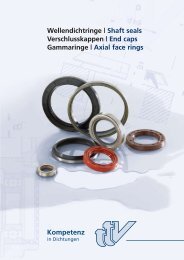
O-<strong>Ringe</strong> | o-<strong>rings</strong><br />
X-<strong>Ringe</strong> | x-<strong>rings</strong><br />
Kompetenz<br />
in Dichtungen
Unternehmen | Company<br />
Die TTV GmbH wurde in Süddeutschland<br />
-nähe Ulm- als Handelsunternehmen für<br />
Dichtungen und technische Teile im Jahre<br />
1990 gegründet.<br />
Hauptsächlich verstehen wir uns als<br />
Zulieferer sowohl für Endkunden wie auch<br />
für Händler der Antriebstechnik, Motorenund<br />
Pumpenherstellern.<br />
Die Zielvorgabe ist eine Alternative für<br />
Lieferungen im Umfeld des wachsenden<br />
Marktes in der Automation des Maschinen-<br />
und Anlagenbaus zu bieten. Der<br />
wesentliche Fokus liegt dabei, ein qualitatives,<br />
technisch anerkanntes und preislich<br />
interessantes Produkt nach DIN Standard,<br />
sowie Sonder-Kundenwunsch-Teilen der<br />
Dichtungs- und Gleitlagertechnik anzubieten.<br />
Dabei vertrauen wir erfolgreich auf<br />
bewährte und von uns ausgewählte<br />
Herstellerbetriebe, die wie wir selbst nach<br />
DIN EN ISO 9001:2008 zertifiziert sind.<br />
Kompetenz<br />
in Dichtungen<br />
The TTV GmbH was founded in Southern<br />
Germany – close to Ulm – in 1990 as a<br />
retail firm for seals and technical components.<br />
We consider ourselves above all as a<br />
supplier for end customers as well as drive<br />
engineering retail firms and pump and<br />
engine manufactures.<br />
Our aim is to offer an alternative as to<br />
supplies for the growing market of drive<br />
technology automation. Our main focus is<br />
to offer a high-quality, technically<br />
acknowledged and cost-effective product<br />
according to DIN standards as well as<br />
customized sealing parts and slidung<br />
bea<strong>rings</strong>.<br />
Here we successfully rely on proven<br />
manufacturing companies chosen by us,<br />
who are, like us, certified according to DIN<br />
EN ISO 9001:2008.
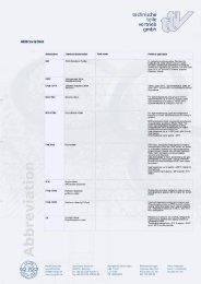
X-<strong>Ringe</strong> | x-<strong>rings</strong> | O-<strong>Ringe</strong> | o-<strong>rings</strong><br />
Inhaltsverzeichnis | Table of Contents<br />
Allgemeines | General...........................................................................................................................................4<br />
Wirkungsweise........................................................................................................................................................5<br />
Working Principle...................................................................................................................................................6<br />
Werksto�e | Materials ...........................................................................................................................................7<br />
Werksto�e - Temperatur und Umgebung | Materials - Temperature and environment .............8<br />
Ober�ächenbehandelte O-<strong>Ringe</strong> .....................................................................................................................9<br />
Surface treated o-<strong>rings</strong>...................................................................................................................................... 10<br />
O-Ring Nutgeometrie ........................................................................................................................................ 11<br />
O-ring keyway geometry.................................................................................................................................. 12<br />
O-Ring Einbauarten | Types of �tting for o-<strong>rings</strong>..................................................................................... 13<br />
O-<strong>Ringe</strong> unter Druck | O-<strong>rings</strong> under pressure......................................................................................... 14<br />
O-Ring und Stützring Aufbau ......................................................................................................................... 15<br />
Fitting of o-<strong>rings</strong> and backup <strong>rings</strong> .............................................................................................................. 16<br />
X-<strong>Ringe</strong> | x-<strong>rings</strong>.......................................................................................................................................... 17 / 18
O-<strong>Ringe</strong> | o-<strong>rings</strong><br />
Allgemeines | General<br />
4<br />
Ein O-Ring ist eine Dichtung zur Verhinderung<br />
des unerwünschten Austretens oder<br />
des Verlustes von Medien.<br />
Der O-Ring ist die am weitesten verbreitete<br />
Dichtung, weil sie einfach und leicht zu<br />
montieren ist und wenig Einbauraum<br />
benötigt. Bei richtiger Nutauslegung und<br />
Werkstoffauswahl kann eine Dichtung<br />
dynamisch sowie statisch, innerhalb der<br />
Temperaturgrenzen des Werkstoffs,<br />
eingesetzt werden.<br />
Beschreibung<br />
Ein O-Ring ist ein geschlossener Ring mit<br />
kreisrundem Querschnitt, vorwiegend aus<br />
einem Elastomer hergestellt .<br />
ø d 1<br />
O-Ring-Bemaßung<br />
O-<strong>Ringe</strong> werden aus unterschiedlichen<br />
Elastomeren in beheizten Spritz- oder<br />
Pressformen stoß- und nahtlos durch<br />
Vulkanisieren (Vernetzen) hergestellt.<br />
Unsere O-<strong>Ringe</strong> werden nach DIN 3771<br />
gefertigt und kontrolliert.<br />
d 2<br />
An o-ring is a seal to avoid adverse<br />
leakage or loss of media.<br />
The o-ring is the most common seal<br />
because it is easy and straightforward to<br />
fit and requires a minimum clearance.<br />
With proper keyway dimensioning and<br />
choice of material a seal can be applied<br />
dynamically as well as statically within the<br />
materials range of operating temperature.<br />
Description<br />
An o-ring is given by a closed ring with<br />
circular cross section mainly produced of<br />
elastomer.<br />
ø d 1<br />
o-ring dimensioning<br />
O-<strong>rings</strong> are produced of different elastomers<br />
joint- and seamlessly in heated<br />
extrusion or press moulds by vulcanisation<br />
(polymerisation).<br />
Our o-<strong>rings</strong> are produced and controlled<br />
according to DIN 3771.<br />
d 2
Wirkungsweise<br />
Die Dichtwirkung des O-Rings wird durch<br />
die Verformung seines Querschnitts d2 in<br />
einer Nut erzeugt. Der Querschnitt wird<br />
verformt, dadurch wird der Dichtspalt an<br />
der Kontakt- bzw. Dichtfläche und am<br />
Nutgrund verschlossen. Somit wird eine<br />
Flächenpressung erzeugt, die eine<br />
Dichtwirkung möglich macht. Die maximale<br />
Verformung des O-Ring-<br />
Querschnitts hängt wesentlich von der<br />
Nuttiefe ab.<br />
Wichtiger Hinweis<br />
Der Schnurdurchmesser d2 muss stets<br />
größer sein als die Tiefe des Einbauraums.<br />
Die Verformung wird als prozentuale<br />
Verpressung angegeben. Als Verpressung<br />
wird jener Prozentanteil des Schnurdurchmessers<br />
d2 bezeichnet, um den dieser im<br />
Einbauzustand zusammengepresst wird.<br />
Die Verpressung steht somit in direktem<br />
Zusammenhang mit der Nuttiefe. Bei<br />
gleicher prozentualer Verpressung<br />
nehmen die Verformungskräfte mit<br />
zunehmender Schnurstärke d2 zu. Um<br />
diese auszugleichen wird die prozentuale<br />
Verpressung mit zunehmendem Schnurdurchmesser<br />
verringert.<br />
Nutgrund<br />
Dicht�äche<br />
Flächenpressung<br />
Verpresster O-Ring im Einbauraum<br />
ohne Druckbeaufschlagung<br />
Vorhandener Druck kann für die Abdichtung<br />
vorteilhaft sein. Dieser verpresst den<br />
O-Ring zusätzlich , die Druckwirkung wird<br />
in gewissen Bereichen unterstützt.<br />
Druck presst den O-Ring an die druckabgewandte<br />
Nutseite. Um eine Spaltwanderung<br />
des O-Rings zu vermeiden, sollte<br />
dieser möglichst klein gehalten werden.<br />
Bei radialer Abdichtung ist eine Toleranz<br />
von H8/f7 vorzusehen, bei axialer Abdichtung<br />
H11/h11.<br />
Sollte dies nicht sichergestellt werden<br />
können oder sind hohe Drücke zu erwarten,<br />
sollte eine möglichst hohe Werkstoffhärte<br />
für den O-Ring gewählt werden.<br />
Andernfalls kann es zu einer so genannten<br />
Spaltwanderung und somit zur<br />
Zerstörung des O-Rings kommen.<br />
Druckrichtung<br />
Druckverteilung<br />
Verpresster O-Ring im Einbauraum<br />
unter Druckbeaufschlagung<br />
Flächenpressung<br />
5
O-<strong>Ringe</strong> | o-<strong>rings</strong><br />
Working principle<br />
6<br />
The sealing effect of the o-ring is based<br />
on the deformation of its profile d2 within<br />
a keyway. The profile is distorted thereby<br />
closing the sealing gap at the contactand<br />
sealing surface on the bottom of the<br />
keyway. Thus a surface press fit is generated<br />
that provides the sealing effect. The<br />
maximum deformation of the o-ring<br />
profile substantially depends on the<br />
keyway depth.<br />
Important note<br />
The cord diameter d2 must always exceed<br />
the clearance depth.<br />
This deformation is specified as the<br />
percentage grouting. Grouting refers to<br />
the percentage the cord diameter d2 is<br />
compressed under fitting conditions.<br />
Grouting thus is a direct function of the<br />
keyway depth. With constant percentage<br />
grouting the forces of deformation are an<br />
increasing function of the cord diameter<br />
d2. In order to compensate these forces<br />
the percentage grouting is reduced with<br />
increasing cord diameter.<br />
keyway bottom<br />
sealing<br />
surface<br />
surface press �t<br />
Grouted o-ring in clearance without pressure<br />
impact<br />
The existing pressure (exerted by the<br />
medium) can be favorable for the sealing.<br />
The o-ring is squeezed further in and the<br />
effect of pressure in certain areas is being<br />
reinforced.<br />
Under pressure the o-ring is being squeezed<br />
at the keyway side leeward to the<br />
pressure. In order to avoid a gap drift of<br />
the o-ring seal the clearance should be as<br />
small as possible.<br />
With radial sealing a tolerance H8/f7 is to<br />
be provided, with axial sealing it is H1/h11.<br />
In case this cannot be ensured or high<br />
pressure is expected the material hardness<br />
for the o-ring should be chosen as<br />
high as possible. Otherwise a so called<br />
gap drift may occur and lead to destruction<br />
of the o-ring.<br />
surface press �t<br />
pressure<br />
direction<br />
pressure distribution<br />
Grouted o-ring with pressure impact
Werkstoffe | Materials<br />
Technische Gummiwerkstoffe unterliegen<br />
einer exakten Rezeptur. Im Vergleich der<br />
abzudichtenden Medien aller enthaltenen<br />
Mischungsbestandteilen ist das Polymer<br />
in Bezug auf die chemische Beständigkeit<br />
das schwächste Material.<br />
Die Auswahl des richtigen Dichtungswerkstoffes<br />
beschränkt sich daher oftmals<br />
auf die richtige Wahl des Basispolymers. In<br />
der Praxis können weitere rezepturbedingte<br />
Einflüsse wie z.B. die Art und<br />
Menge der eingesetzten Weichmacher<br />
und Füllstoffe die Eigenschaften entscheidend<br />
verändern.<br />
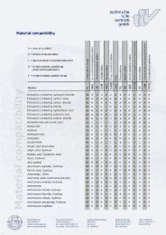
Die Polymerverträglichkeit allein ist noch<br />
kein Garant für sicheres Dichten, aber sie<br />
ist eine wichtige Voraussetzung.<br />
Inhaltssto� Anteil in %<br />
Kautschuk (Polymer) 40<br />
Füllsto�e 35<br />
Weichmacher 20<br />
Verarbeitungshilfsmittel 1,3<br />
Alterungsschutzmittel 1,3<br />
Aktivatoren 1<br />
Vernetzungsmittel 0,8<br />
Beschleuniger 0,6<br />
Mischungsbestandteile einer<br />
Beispielrezeptur<br />
Technical rubber materials are subject to a<br />
distinct formula. Compared to the media<br />
to be sealed among all of the compound<br />
components the polymer constitutes the<br />
weakest material with respect to chemical<br />
resistiveness.<br />
Hence, the choice of the right sealing<br />
material is often limited to exclusively<br />
choosing the right polymer basis. In<br />
practise further influences related to the<br />
formula like for instance the type and<br />
amount of softener and filler used can<br />
substantially alter the properties.<br />
The polymer compatibility does not<br />
account for the secure sealing by itself,<br />
however, it is an important prerequisite.<br />
contents percentage<br />
rubber (Polymer) 40<br />
�ller 35<br />
softener 20<br />
Auxiliary processing means 1,3<br />
Durability means 1,3<br />
activators 1<br />
cross-linkage means 0,8<br />
catalysts 0,6<br />
compound components of an<br />
example formula<br />
7
O-<strong>Ringe</strong> | o-<strong>rings</strong><br />
Werkstoffe | Materials<br />
Temperatur und Umgebung | Temperature and environment<br />
8<br />
HAUPTMATERIALIEN<br />
MAIN MATERIALS<br />
NITRIL<br />
NBR<br />
NITRILE<br />
NBR<br />
FLUORKOHLENSTOFF<br />
FKM<br />
FLUORIC CARBON<br />
FKM<br />
SILIKON<br />
VMQ<br />
SILICONE<br />
VMQ<br />
ETHYLEN<br />
PROPYLEN<br />
EP<br />
ETHYLENE<br />
PROPYLENE<br />
EP<br />
CHLOROPREN<br />
CR<br />
CHLOROPRENE<br />
CR<br />
PTFE<br />
PTFE<br />
HNBR<br />
HNBR<br />
TEMPERATURBESTÄNDIGKEIT<br />
TEMPERATURERESISTANCE<br />
IN °C<br />
-25 bis +120<br />
-25 to +120<br />
-15 bis +240<br />
-15 to +240<br />
-60 bis +225<br />
-60 to +225<br />
-45 bis +110<br />
-45 to +110<br />
-40 bis +120<br />
-40 to +120<br />
-150 bis +260<br />
-150 to +260<br />
-35 bis +150<br />
-35 to +150<br />
EINSATZBEREICH<br />
APPLICATIONS<br />
Hydrauliköl, Schmierfett,<br />
Kohlenwassersto�, Öl, Fette,<br />
P�anzöl, Wasser, Butan, Druckluft<br />
hydraulic oil, grease, hydrocarbons, oils,<br />
lubricants, vegetable oil, water, butane,<br />
compressed air<br />
Gute Ölbeständigkeit, hydraulische<br />
Flüssigkeiten, Lösungsmittel,<br />
entzündbare Öl und Chemikalien, Ozon<br />
high oil resistance, hydraulic �uids,<br />
solvents, use with in�ammable oils and<br />
chemicals, ozone<br />
Tiefe und hohe Temperaturen, Luft,<br />
Sauersto�, Inertgas, schwache Säure<br />
und Basen, Ozon<br />
Low and high temperatures, air, oxygen,<br />
low concentrated bases and acids<br />
Lebensmittelbeständig (wenn<br />
peroxydvernetzt) : Wasser, Getränke ;<br />
Benutzung mit entzündbaren<br />
Flüssigkeiten, Dampf, verschiedene<br />
Säure, Soda, Glykol, Ozon, warmes<br />
Wasser<br />
food resistant (when peroxidic crosslinked):<br />
water, drinks, use with in�ammable<br />
liquids, vapour, diverse acids,<br />
caustic soda, glycols, ozone, hot water<br />
Luft, Ozon, Wasser bis 80 °C, P�anzenöl,<br />
Sauersto�, Soda, Chlor, Fettalkohol,<br />
Kühlgas, Lebensmittelbereich, CO2<br />
Air, ozone, water up to 80°C, vegetable<br />
oils, oxygen, caustic soda, fatty alcohol,<br />
chlorine, refrigerant gas, alimentary<br />
applications, CO2<br />
Sehr gute chemische Beständigkeit,<br />
guter elektrische Isoliersto�, niedriger<br />
Reibungskoe�zient<br />
excellent chemical resistance, electric<br />
insulator, low friction coe�cient<br />
Ozon, UV, Warmes Wasser, Schwefel<br />
enthaltende Öle<br />
Ozone, UV, hot water, sulphureous oils<br />
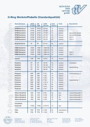
Andere Materialien und Mischungen auf Anfrage. Other materials and compounds on request.<br />
O-<strong>Ringe</strong> mit den obigen Zulassungen (in manchen Fällen auch mit mehreren Zulassungen)<br />
bieten wir auf Anfrage an. Informationen zur Nutauslegung finden Sie auf unserer Homepage<br />
www.<strong>ttv</strong>-gmbh.de oder weiter hinten.<br />
O-<strong>rings</strong> opposite admission (in some cases also with multiple admission) are provided on request.<br />
Information on the keyway dimensioning can be found on our website www.<strong>ttv</strong>-gmbh.de
Oberflächenbehandelte O-<strong>Ringe</strong><br />
O-<strong>Ringe</strong> sind ohne Oberflächenbehandlung in vielen Fällen schwer serienweise einzusetzen.<br />
Unsere Erfahrung in Industriebereichen erlaubt es uns, Ihnen folgende Oberflächenbehandlungen<br />
anzubieten. Diese sind empfohlen bzw. nötig, um den Reibungskoeffizient eines O-<strong>Ringe</strong>s zu<br />
verbessern. Die Montage der Teile wird somit erleichtert, besonders wenn Gummi-Teile automatisch<br />
montiert werden.<br />
BEHANDLUNGSTYP BESCHREIBUNG FARBE / ASPEKT<br />
Silikonierung<br />
Ein Silikon�lm wird auf die zu<br />
behandelnden Teile gespritzt.<br />
Glänzend, fett<br />
Transparent<br />
Molykotierung<br />
Molybden Pulver-Beschichtung<br />
durch Auftrommeln.<br />
Silberartig<br />
Talkumierung<br />
Talkum Pulver-Beschichtung durch<br />
Auftrommeln.<br />
Trocken<br />
Weiß<br />
PTFE Pulver-<br />
PTFE Pulver-Beschichtung durch Trocken<br />
Beschichtung<br />
Auftrommeln.<br />
Weiß<br />
LABS-FREI O-RINGE (frei von Lackbenetzungs-störenden Substanzen)<br />
LABS sind Substanzen, die beim Lackieren von Oberflächen Krater (punktuelle, trichterförmige<br />
Vertiefungen) in der Lackschicht verursachen. In diesem Rahmen sind LABS-freie-Mischungen<br />
und entsprechende Prüfsysteme entwickelt worden. Diese werden meistens bei Zulieferanten<br />
der Automobilindustrie eingesetzt.<br />
Um die angeforderten Kriterien eines LABS-freien Teiles zu gewährleisten, haben wir folgende<br />
Maßnahmen festgestellt:<br />
• LABS-freie O-<strong>Ringe</strong> und Formteile werden aus entwickelten LABS-freien Mischungen<br />
hergestellt (NBR- und FKM-Mischungen zur Verfügung).<br />
• Der vollständige Herstellungsprozess ist LABS-frei kontrolliert.<br />
Dadurch werden die Teile von der Mischungsherstellung bis zu der Verpackung kontrolliert.<br />
Bei Bedarf bieten wir auch spezielle Verpackungen, welche die Ebenheit und Rundheit von<br />
Teilen gewährleisten.<br />
9
O-<strong>Ringe</strong> | o-<strong>rings</strong><br />
Surface treated o-<strong>rings</strong><br />
10<br />
It is often difficult to use o-<strong>rings</strong> without surface treatment in automatic assembly.<br />
Our experience in industrial fields enables us to offer you the following surface treatments.<br />
These are recommended respectively necessary to improve the o-ring friction coefficient.<br />
The assembly of the parts is simplified in this way especially if rubber parts are mounted<br />
automatically.<br />
TYPE OF TREATMENT DESCRIPTION COLOR / APPERANCE<br />
Silicone treatment<br />
silicon �lm is sprayed onto the<br />
treated parts<br />
bright, greasy,<br />
colorless<br />
MoS2 powder coating<br />
molybdenum powder coating by<br />
reeling<br />
silver color<br />
Talcum powder coating<br />
talcum powder coating by<br />
reeling<br />
dry, white<br />
PTFE powder coating PTFE powder coating by reeling white<br />
LABS-free o-<strong>rings</strong> (o-<strong>rings</strong> free of substances impairing paint wetting)<br />
LABS are substances that cause craters (localized funnel shaped dents) in paint finishes applied<br />
to surfaces. In this context LABS-free compounds and corresponding test systems have been<br />
developed. These are applied at suppliers of the automotive industry.<br />
In order to meet the required criteria for LABS-free parts we set up the following actions:<br />
• LABS-free o-<strong>rings</strong> and molded parts produced of LABS-free compounds<br />
(NBR and FKM compounds at your disposal)<br />
• controlled LABS-free manufacturing process<br />
This way the parts are monitored from the compound production until packaging.<br />
On request we can provide you with special packaging that ensures the evenness<br />
and roundness of all parts.
O-Ring Nutgeometrie<br />
Um eine entsprechende Dichtfunktion<br />
übernehmen zu können, ist es notwendig<br />
die O-<strong>Ringe</strong> in dafür hergestellte Nuten<br />
einzulegen. Für die Verpressung des<br />
O-Rings ist die Nuttiefe verantwortlich.<br />
Die Abbildung unten zeigt die Darstellung<br />
einer Rechtecknut mit Bemaßung, wie sie<br />
auch in den entsprechenden Normen<br />
empfohlen wird.<br />
C<br />
A<br />
15°-20°<br />
B<br />
Darstellung einer typischen Rechtecknut<br />
Beschreibung:<br />
t = radiale Nuttiefe<br />
b = Nutbreite<br />
h = Höhe des Einbauraums<br />
g = Dichtspalt (Spaltmaß)<br />
P = Mediendruck<br />
A = Oberfläche der Gegenlauffläche<br />
B = Oberfläche der Nutflanken und<br />
des Nutgrunds<br />
C = Oberfläche der Einführungsschräge<br />
P<br />
B<br />
b<br />
B<br />
g<br />
h<br />
t<br />
Festlegung der Nuttiefe t<br />
Die Schnurstärke d2 und die Nuttiefe<br />
bestimmen die ursprüngliche Verpressung.<br />
Die Wahl der Nuttiefe hängt von der<br />
jeweiligen Anwendung ab. Bei einem<br />
statischen Einsatz sollte die ursprüngliche<br />
Verpressung zwischen 15 % und 30 %<br />
betragen. Bei einem dynamischen Einsatz<br />
sollte die Nuttiefe größer und somit eine<br />
geringere Verpressung gewählt werden.<br />
Hier empfiehlt sich eine Verpressung<br />
zwischen 6 % bis 20 %.<br />
Festlegung der Nutbreite b<br />
Die Nutbreite ergibt sich aus der Schnurstärke<br />
d2 des O-Rings und der ovalen Form<br />
nach der Verpressung zuzüglich eines<br />
Freiraumes, in den das Medium treten<br />
kann, um eine gleichmäßige<br />
Druckbeaufschlagung auf die Dichtung<br />
zu gewährleisten.<br />
Bei der Bemessung der Nutbreite ist<br />
unbedingt eine Nutüberfüllung zu vermeiden.<br />
Deshalb wird üblicherweise bei der<br />
Konstruktion einer Nut davon ausgegangen,<br />
dass der O-Ring diese zu 80 % bis<br />
85 % ausfüllen sollte, damit er noch Platz<br />
hat, sich im Falle einer Volumenzunahme<br />
ausdehnen zu können.<br />
Die Nutbreite ist einer möglichen Volumenzunahme<br />
des O-Rings anzupassen.<br />
11
O-<strong>Ringe</strong> | o-<strong>rings</strong><br />
O-ring keyway geometry<br />
12<br />
In order to fulfil a proper sealing function<br />
the o-ring seal is required to be inserted<br />
into keyways that are manufactured for<br />
this purpose. For the grouting of the<br />
o-ring the keyway depth is responsible.<br />
The figure below shows a representation<br />
of a rectangular keyway with dimensioning<br />
also recommended in the corresponding<br />
norms.<br />
C<br />
A<br />
15°-20°<br />
B<br />
Representation of a typical rectangular<br />
keyway<br />
Description:<br />
t = radial keyway depth<br />
b = keyway width<br />
h = clearance height<br />
g = sealing gap (gap measure)<br />
P = media pressure<br />
A = surface of the opposite facing surface<br />
B = surface of the keyway sidewalls and the<br />
keyway bottom<br />
C = surface of the insertion bevel<br />
P<br />
B<br />
b<br />
B<br />
g<br />
h<br />
t<br />
Determination of the keyway depth t<br />
The cord diameter d2 and the keyway<br />
depth determine the original grouting.<br />
The choice of the keyway depth depends<br />
on the individual application. For static use<br />
the original grouting is recommended<br />
between 15 % and 30 %. For dynamic use a<br />
higher keyway depth and less respective<br />
grouting should be chosen. In this case a<br />
grouting between 6 % to 20% is advisable.<br />
Determination of the keyway width b<br />
The keyway width results from the cord<br />
dimension d2 of the o-ring seal and its<br />
oval shape after grouting plus a clearance<br />
the medium can intrude into, in order to<br />
ensure a uniform pressure impact onto the<br />
seal.<br />
In dimensioning the keyway depth a<br />
keyway congestion must be avoided.<br />
Therefore in keyway design the o-ring is<br />
commonly presumed to occupy 80 % to 85<br />
% of the keyway in order to provide<br />
enough space for expansion in case its<br />
volume is increasing.<br />
The keyway width must be adapted to a<br />
potential increase in volume of the o-ring<br />
seal.
O-Ring Einbauarten | Types of fitting for o-<strong>rings</strong><br />
Für den Einbau von O-<strong>Ringe</strong>n gibt es<br />
mehrere Möglichkeiten.<br />
Man unterscheidet grundsätzlich, je nach<br />
Verformungsrichtung, nach axialer oder<br />
radialer Verformung. Des Weiteren unterscheidet<br />
man bei radialer Verformung<br />
nach "außendichtend" (Kolbendichtung,<br />
Nut im Kolben - Innenteil) und "innendichtend"<br />
(Stangendichtung, Nut im<br />
Gehäuse - Außenteil).<br />
Die meisten O-<strong>Ringe</strong> werden als statisch<br />
beanspruchte Dichtungen eingesetzt.<br />
Erfolgt die Abdichtung<br />
zwischen Maschinenteilen, die sich<br />
zueinanderbewegen, entspricht das der<br />
dynamischen Abdichtung.<br />
Als dynamische Dichtung sind O-<strong>Ringe</strong><br />
nur bedingt als optimale technische<br />
Lösung verwendbar.<br />
a) Flanschdichtung | Flange sealing<br />
Die Nut befindet sich im Flansch und<br />
wird mit einem Deckel verschraubt.<br />
The keyway is located at the flange and is<br />
screwed with a lid.<br />
There are several fitting types for o-<strong>rings</strong>.<br />
Basically according to the direction of<br />
deformation axial and radial deformation<br />
are distinguished.<br />
Furthermore, with radial deformation<br />
„outward sealing“ (piston seal, keyway in<br />
the interior of the piston) and „inward<br />
sealing“ (rod seal, keyway in the outer part<br />
of the housing) are distinguished.<br />
Most o-<strong>rings</strong> are used as statically stressed<br />
seals. If the sealing is performed between<br />
machine parts that are mutually moving<br />
this corresponds to dynamic sealing.<br />
As dynamic seal o-<strong>rings</strong> achieve only a<br />
limited optimal technical solution.<br />
b) Kolbendichtung | Piston sealing<br />
c) Stangendichtung | Rod sealing<br />
13
O-<strong>Ringe</strong> | o-<strong>rings</strong><br />
O-<strong>Ringe</strong> unter Druck | O-<strong>rings</strong> under pressure<br />
14<br />
Die Neigung zur Extrusion / Spaltwanderung<br />
wird weitgehend vom Spaltmaß<br />
zwischen den Maschinenteilen beeinflusst.<br />
Das Spiel hängt von der Bearbeitung,<br />
der Fertigungsmethode, den Toleranzen,<br />
die auf das Spiel Einfluss nehmen und<br />
dem Atmen der Teile unter Druck, etc. ab.<br />
Wichtiger Hinweis<br />
Das Spaltmaß sollte so gering wie<br />
möglich ausgeführt werden.<br />
Druckrichtung<br />
Verhalten des O-Rings unter Druck<br />
Ein zu großer Dichtspalt kann durch<br />
Spaltwanderung zur Zerstörung des<br />
O-Rings führen.<br />
Druckrichtung<br />
Extrudierter O-Ring<br />
O-<strong>Ringe</strong> in einer Härte von 90 Shore A<br />
erlauben geringfügig größere Spaltweiten<br />
als Standard-O-<strong>Ringe</strong> in 70 Shore A.<br />
Auf unserer Homepage finden Sie die<br />
Richtwerte der Spaltmaße für Standardelastomere,<br />
bei zentrischer Anordnung.<br />
g<br />
The tendency to extrusion / gap drift<br />
mostly depends on the gap measure<br />
between the machine parts. The slackness<br />
is determined by the processing, the<br />
manufacturing procedure, the tolerances<br />
influencing the clearance and breathing<br />
of the parts under pressure, etc.<br />
Important note<br />
It is advised to implement the clearance<br />
measure as small as possible.<br />
direction of<br />
pressure<br />
Characteristics of the o-ring under pressure<br />
A larger seal clearance can result in the<br />
destruction of the o-ring for instance by<br />
gap drift.<br />
direction of<br />
pressure<br />
Extruded o-ring seal<br />
O-ring seals with hardness 90 shore A<br />
admit slightly larger gaps than standard<br />
o-ring seals of 70 shore A.<br />
On our homepage you will find the<br />
reference values of clearance dimensions<br />
for standard elastomers in a centric<br />
configuration.<br />
g
O-Ring und Stützring Aufbau<br />
1) NBR 90<br />
Die Hauptfunktion eines Stützringes ist die Verhinderung der<br />
Spaltwanderung unter Druckeinwirkung, wenn das Spaltmaß groß ist.<br />
Der Stützring verhindert dies konzequent und infolgedessen die<br />
schnelle O-Ringszerstörung.<br />
Einbau<br />
Der Einbau ist einfach und schnell. Der Stützring wird an der<br />
druckabgewandten Seite eingebaut.<br />
Im Falle einer doppeltwirkenden Dichtung können zwei Stützringe<br />
beidseitig eingebaut werden.<br />
Vorteile dieser Montage<br />
Die Lebensdauer der Dichtung wird verlängert.<br />
Die Kosten des Dichtungssystems sind niedrig:<br />
es ermöglicht eine weitere Toleranz der abzudichtenden<br />
Teile und vermindert dadurch die<br />
Bearbeitungskosten.<br />
Einsatzbedinungen<br />
Temperaturen von –30°C bis +120°C<br />
Druckverhalten: siehe nachfolgendes Diagramm<br />
Die Härte des verwendeten O-<strong>Ringe</strong>s beeinflusst die Einsatzbedingungen.<br />
2) PTFE-STÜTZRING<br />
Die Funktion eines PTFE-Stützringes ist ähnlich der eines<br />
Stützringes aus NBR, jedoch besitzt er ein breiteres<br />
Einsatzspektrum.<br />
Temperaturen von –150°C bis +250°C<br />
8TT<br />
(geschlitzt<br />
oder nicht)<br />
9TT<br />
(geschlitzt<br />
oder nicht)<br />
Für Sonderprofile, wie bspw. Spiral-<strong>Ringe</strong>, nehmen Sie bitte Kontakt mit uns auf.<br />
Einsatzdruck (bar)<br />
600<br />
400<br />
300<br />
200<br />
100<br />
80<br />
60<br />
40<br />
30<br />
20<br />
10<br />
8<br />
Kein Extrudieren<br />
Selektionsdiagramm der Härte<br />
von statischen O-<strong>Ringe</strong>n<br />
Härte Shore A 70 80 90<br />
0,1 0,2 0,3 0,4 0,5 0,6 0,7 0,8 0,9 1,0<br />
S = Total Durchmesserspiel (mm)<br />
Grenze mit NBR-Stützring<br />
Extrudieren<br />
Grenze mit<br />
PTFE-Stützring<br />
15
O-<strong>Ringe</strong> | o-<strong>rings</strong><br />
Fitting of o-<strong>rings</strong> and back up <strong>rings</strong><br />
16<br />
1) NBR 90<br />
The main function of a back up ring is to prevent the seal from gap drift unter pressure<br />
impact if the clearance is too large. The back up ring persistently avoids this scenario<br />
and as a result the fast destruction of the o-ring is averted.<br />
Fitting<br />
Fitting can be done easily and quickly. The back up ring is<br />
implemented on the side opposite the pressurized surface<br />
of the o-ring. In case of a double acting seal two back up <strong>rings</strong> can<br />
be installed doublesidedly.<br />
Advantages of this type of fitting<br />
The life time of the seal is being extended.<br />
The cost of the sealing system is low:<br />
It enables a wide tolerance of the parts to seal<br />
and results in reduced machining cost.<br />
Operating conditions<br />
temperature range -30 °C to +120 °C<br />
pressure characteristics: see following figure<br />
The hardness of the o-ring used affects the operating conditions.<br />
2) PTFE back up ring<br />
The function of a PTFE back up ring is similar to the NBR<br />
back up ring, however it provides a wider field of use.<br />
temperature range -150 °C to +250 °C<br />
ST8<br />
(split<br />
or not)<br />
ST9<br />
(split<br />
or not)<br />
For special profiles like e.g. helical <strong>rings</strong> please get into contact with us.<br />
operating pressure (bar)<br />
600<br />
400<br />
300<br />
200<br />
100<br />
80<br />
60<br />
40<br />
30<br />
20<br />
10<br />
8<br />
no extrusion<br />
Selection diagram for the<br />
hardness of static o-<strong>rings</strong><br />
hardness shore A 70 80 90<br />
extrusion<br />
0,1 0,2 0,3 0,4 0,5 0,6 0,7 0,8 0,9 1,0<br />
S = total diameter slackness (mm)<br />
limit with NBR back up ring<br />
limit with PTFE<br />
back up ring
X-<strong>Ringe</strong> | x-<strong>rings</strong><br />
Beschreibung<br />
X-<strong>Ringe</strong> sind doppelt dichtende Vierlippendichtungen,<br />
die sich durch ein quadratisches<br />
Profil kennzeichnen. Der X-Ring<br />
wird durch seinen Innendurchmesser d1<br />
und seine Wandstärke d definiert.<br />
Wirkungsweise<br />
Ein X-Ring ist symetrisch. Er passt sich<br />
einwandfrei an. Unabhängig davon, aus<br />
welcher Richtung Kräfte auf ihn einwirken<br />
(radial, axial). Die Verpressung ist fortschreitend,<br />
abhängig vom Druck, der die<br />
Radialwandstärke erhöht.<br />
Bei hohem Druck raten wir Ihnen, Stützringe<br />
zu benutzen.<br />
P=Druck<br />
Vorteile<br />
Kein Verwindungsrisiko.<br />
Niedriger Reibwert:<br />
• gleitfähige Materialien<br />
• niedrige Vorspannung<br />
• Fettreserve zwischen den Lippen<br />
Eine bessere Abdichtung (in Bezug auf<br />
den O-Ring) wird hauptsächlich durch<br />
einen doppelten Kontakt bewirkt.<br />
P<br />
P<br />
Ø d1<br />
Description<br />
X-<strong>rings</strong> are double sealing four-lobe seals<br />
that are characterised by their square profile.<br />
The x-ring is definded by its inner diameter<br />
d1 and its wall thickness d.<br />
d<br />
d<br />
Working Principle<br />
Because of its symmetrical shape the x-ring<br />
can adapt to every situation and withstand<br />
stress in any direction (radial, axial). An<br />
increase in pressure makes grouting<br />
progress and the radial wall thickness<br />
increase.<br />
At high pressure we recommend the<br />
use of support <strong>rings</strong>.<br />
p=pressure<br />
P<br />
P<br />
Advantages<br />
No twisting.<br />
Low friction coefficient due to:<br />
• slippery material<br />
• low pre-stressing<br />
• lubricant reservoir between lobes<br />
An improved sealing (with respect to the<br />
o-ring) is accomplished mainly by means of<br />
a double contact.<br />
17
X-<strong>Ringe</strong> | x-<strong>rings</strong><br />
18<br />
Durch seine Geometrie kann er bei<br />
dynamische Anwendungen mit drehenden<br />
Bewegungen (1m/s) eingesetzt<br />
werden.<br />
Anwendung<br />
Dynamisch:<br />
Hubkolben, Stangen, Kolben...<br />
Antriebswellen und Spindeln<br />
Statisch:<br />
Radiale und Axiale Abdichtung für jede<br />
Anwendung<br />
Druck:<br />
bis 400 bar mit einem Stützring<br />
(ohne Stützring auf 50 bar begrenzt,<br />
Spielraum von 0,3 bis 0,4 mm).<br />
Geschwindigkeit:<br />
bis zu 0,5-1 m/s<br />
Einsatztemperatur<br />
50 °C bis + 200°C je nach Werkstoff.<br />
Montage<br />
Die Ecken der oberen Nut müssen unbedingt<br />
gratfrei und frei von jeglicher<br />
Markierung sein, um die <strong>Ringe</strong> nicht zu<br />
beschädigen.<br />
Eine kleine Rille in der Nut ist jedoch<br />
zulässig.<br />
Die Nut muss breiter als die Dichtung sein,<br />
um ihre Druckverformung zu berücksichtigen.<br />
Die zu dichtende Flüssigkeit muss sauber<br />
sein.<br />
Oberflächenzustand:<br />
Bohrung und Welle Ra = 0.2 bis 0.6 µm<br />
F =<br />
p Ø<br />
d - 18%<br />
d - 6%<br />
F<br />
+ 0<br />
ID = Ø d – 5%<br />
Due to its geometry it can be used in dynamic<br />
applications with rotary applications (max. 1<br />
m/s) or alternating movement.<br />
Applications<br />
Dynamic:<br />
Reciprocating pistons, rods, pistons, ...<br />
rotary shafts and spindles with limited<br />
pressure and speed<br />
Static:<br />
radial and axial seal for any application<br />
Pressure:<br />
pressure up to 400 bar with anti-extrusion<br />
ring, without support ring limited to 50 bar,<br />
slackness of 0.3 to 0.4 mm)<br />
Speed:<br />
Up to 0.5 – 1 m/s<br />
Operating temperature<br />
From –50°C to +200°C according to the<br />
compound.<br />
Fitting<br />
The edges of the upper keyway must be<br />
absolutely burr-free and without any marking<br />
in order to exclude damage to the <strong>rings</strong>.<br />
A small bottom groove in the keyway is<br />
acceptable however.<br />
The keyway must be wider than the seal in<br />
order to account for the deformation under<br />
pressure.<br />
Side angles may not exceed 3 to 5 % depending<br />
on the application.<br />
The fluid to be sealed must be clean.<br />
Surface roughness:<br />
bore and shaft Ra=0.2 to 0.6 µm<br />
F =<br />
p Ø<br />
d - 18%<br />
d - 6%<br />
F<br />
ID = Ø d<br />
– 0<br />
– 0,3%
Kompetenz in den Bereichen | Compentence in<br />
• Gleitlagertechnik<br />
• Wellendichtungen<br />
• Verschlusskappen<br />
• Gammaringe<br />
• Hydraulikdichtungen<br />
• V-<strong>Ringe</strong><br />
• Drehteile<br />
Kompetenz<br />
in Dichtungen<br />
• Sliding bearing technology<br />
• Shaft seals<br />
• End Caps<br />
• Axial face <strong>rings</strong><br />
• Hydraulic seals<br />
• V-<strong>rings</strong><br />
• CNC turned parts<br />
19
Kompetenz<br />
in Dichtungen<br />
technische teile<br />
vertrieb GmbH<br />
Josef-Henle-Str. 9e<br />
D-89257 Illertissen<br />
Tel. +49 (0) 7303-92874-0<br />
Fax +49 (0) 7303-92874-50<br />
info@<strong>ttv</strong>-gmbh.de<br />
www.<strong>ttv</strong>-gmbh.de