Schmutzfänger Strainers Nr. 300 - VENTEK Armaturen GmbH
Schmutzfänger Strainers Nr. 300 - VENTEK Armaturen GmbH
Schmutzfänger Strainers Nr. 300 - VENTEK Armaturen GmbH

Erfolgreiche ePaper selbst erstellen
Machen Sie aus Ihren PDF Publikationen ein blätterbares Flipbook mit unserer einzigartigen Google optimierten e-Paper Software.
Bestell-<strong>Nr</strong>.<br />
Order no.<br />
PN<br />
Ausführung<br />
Design<br />
Werkstoff<br />
Material<br />
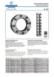
<strong>Schmutzfänger</strong><br />
<strong>Strainers</strong><br />
<strong>Nr</strong>. <strong>300</strong><br />
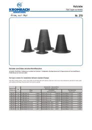
<strong>Schmutzfänger</strong> in Schrägsitzform mit Flanschanschluss<br />
mit auswechselbarem Innensieb aus rost- und säurebeständigem Edelstahlgewebe 1.4401, ab DN 200 mit zusätzlichem Stützsieb aus gelochtem<br />
Edelstahlblech 1.4571.<br />
Baulänge nach DIN EN 558-1, Reihe 1<br />
Flanschanschlussmaße nach DIN.<br />
<strong>Strainers</strong> in “Y” type with flange connection<br />
with exchangeable inside screen made of stainless steel 1.4401, up to DN 200 with additional supporting screen made of stainless steel 1.4571.<br />
Face-to-face dimension acc. to DIN EN 558-1, line 1,<br />
Flanged connection acc. to DIN<br />
SF 301<br />
SF 302<br />
SF 303<br />
SF 304<br />
SF 305<br />
SF 321<br />
SF 322<br />
6<br />
10/16<br />
10/16<br />
16<br />
25<br />
Lieferbare Sonderausführungen:<br />
• andere Maschenweiten<br />
• andere Siebwerkstoffe<br />
• Flansche mit Nut<br />
• mit Ablassventil im Deckel<br />
• SF 321, SF 322 mit Doppelsieb<br />
6<br />
10/16<br />
Einfachsieb/Single-screen<br />
Doppelsieb/Double-screen<br />
(Feinsieb/Fine screen MW 0,25 mm)<br />
Einfachsieb/Single-screen<br />
Doppelsieb/Double-screen<br />
(Feinsieb/Fine screen MW 0,25 mm)<br />
Innengummierung/Inside rubber lined<br />
Einfachsieb/Single-screen<br />
Einfachsieb/Single-screen<br />
Gusseisen/Cast iron<br />
Gusseisen/Cast iron<br />
Gusseisen/Cast iron<br />
Gusseisen/Cast iron<br />
Gusseisen/Cast iron<br />
Sphäroguss/Ductile cast iron<br />
Sphäroguss/Ductile cast iron<br />
Available special designs:<br />
• Other wire cloth<br />
• Other screen materials<br />
• Flange with groove<br />
• With globe valve in the cover<br />
• SF 321, SF 322 with double-screen<br />
EN-GJL-250<br />
EN-GJL-250<br />
EN-GJL-250<br />
EN-GJL-250<br />
EN-GJL-250<br />
EN-GJS-400-18-U-LT<br />
EN-GJS-400-18-U-LT<br />
(EN-JL 1040)<br />
(EN-JL 1040)<br />
(EN-JL 1040)<br />
(EN-JL 1040)<br />
(EN-JL 1040)<br />
(EN-JS 1049)<br />
(EN-JS 1049)
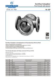
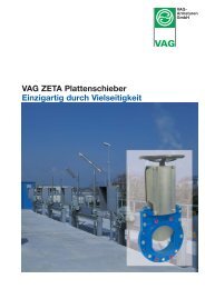
Ausführung SF 301, 302, 303, 304, 321, 322<br />
Design SF 301, 302, 303, 304, 321, 322<br />
Ausführung SF 305<br />
Design SF 305<br />
(ab DN 20 möglich / possible from DN 20)<br />
H Dimension to be considered for screen removal<br />
H Dimension to be considered for screen removal<br />
<strong>Schmutzfänger</strong><br />
<strong>Strainers</strong><br />
<strong>Nr</strong>. <strong>300</strong>
Baumaße und Gewichte<br />
Dimensions and weights<br />
DN PN<br />
15<br />
15<br />
20<br />
20<br />
25<br />
25<br />
32<br />
32<br />
40<br />
40<br />
50<br />
50<br />
65<br />
65<br />
65<br />
80<br />
80<br />
80<br />
100<br />
100<br />
100<br />
125<br />
125<br />
125<br />
150<br />
150<br />
150<br />
200<br />
200<br />
200<br />
200<br />
250<br />
250<br />
250<br />
250<br />
<strong>300</strong><br />
<strong>300</strong><br />
<strong>300</strong><br />
<strong>300</strong><br />
350<br />
350<br />
350<br />
350<br />
Material<br />
Pos.<br />
Item<br />
2<br />
3<br />
3.1<br />
4<br />
5<br />
6<br />
7<br />
8<br />
6<br />
10-25<br />
6<br />
10-25<br />
6<br />
10-25<br />
6<br />
10-25<br />
6<br />
10-25<br />
6<br />
10-25<br />
6<br />
10/16<br />
25<br />
6<br />
10/16<br />
25<br />
6<br />
10/16<br />
25<br />
6<br />
10/16<br />
25<br />
6<br />
10/16<br />
25<br />
6<br />
10<br />
16<br />
25<br />
6<br />
10<br />
16<br />
25<br />
6<br />
10<br />
16<br />
25<br />
6<br />
10<br />
16<br />
25<br />
Baumaße<br />
Flanschanschlussmaße<br />
Sieb Entleerung<br />
Dimensions<br />
Flange dimensions<br />
Screen Discharge<br />
L H1 H D k n x Ø d g f b e s G X<br />
130 60 103 80 55 4 x 11 40 2 12 52 20 G 3/8 0<br />
130 60 103 95 65 4 x 14 45 2 14 52 20 G 3/8 0<br />
150 72 120 90 65 4 x 11 50 2 14 62 25 G 3/8 0<br />
150 72 120 105 75 4 x 14 58 2 16 62 25 G 3/8 0<br />
160 83 140 100 75 4 x 11 60 2 14 74 29 G 3/8 0<br />
160 83 140 115 85 4 x 14 68 2 16 74 29 G 3/8 0<br />
180 91 150 120 90 4 x 14 70 2 16 77 38 G 3/8 0<br />
180 91 150 140 100 4 x 18 78 2 18 77 38 G 3/8 0<br />
200 113 190 130 100 4 x 14 80 3 16 97 50 G 3/8 12<br />
200 113 190 150 110 4 x 18 88 3 18 97 50 G 3/8 12<br />
230 128 215 140 110 4 x 14 90 3 16 112 60 G 3/8 18<br />
230 128 215 165 125 4 x 18 102 3 20 112 60 G 3/8 18<br />
290 181 315 160 130 4 x 14 110 3 16 172 65 G 1/2 20<br />
290 185 315 185 145 4 x 18 122 3 20 172 65 G 1/2 20<br />
290 185 315 185 145 4 x 18 122 3 22 172 65 G 1/2 20<br />
310 205 355 190 150 4 x 18 128 3 18 193 80 G 1/2 30<br />
310 205 355 200 160 8 x 18 138 3 22 193 80 G 1/2 30<br />
310 205 355 200 160 8 x 18 138 3 24 193 80 G 1/2 30<br />
350 265 435 210 170 4 x 18 148 3 18 222 95 G 1 30<br />
350 265 435 220 180 8 x 18 158 3 24 222 95 G 1 30<br />
350 265 435 235 190 8 x 22 162 3 24 222 95 G 1 30<br />
400 285 475 240 200 8 x 18 178 3 20 243 110 G 1 35<br />
400 285 475 250 210 8 x 18 188 3 26 243 110 G 1 35<br />
400 285 475 270 220 8 x 26 188 3 26 243 110 G 1 35<br />
480 328 548 265 225 8 x 18 202 3 20 287 131,5 G 1 45<br />
480 328 548 285 240 8 x 22 212 3 26 287 131,5 G 1 45<br />
480 328 548 <strong>300</strong> 250 8 x 26 218 3 28 287 131,5 G 1 45<br />
600 405 660 320 280 8 x 18 258 3 22 332 180 G 1 72<br />
600 405 660 340 295 8 x 22 268 3 26 332 180 G 1 72<br />
600 405 660 340 295 12 x 22 268 3 30 332 180 G 1 72<br />
600 405 660 360 310 12 x 26 278 3 30 332 180 G 1 72<br />
730 515 880 375 335 12 x 18 312 3 24 510 255,5 G 1 100<br />
730 515 880 395 350 12 x 22 320 3 28 510 255,5 G 1 100<br />
730 515 880 405 355 12 x 26 320 3 32 510 255,5 G 1 100<br />
730 515 880 425 370 12 x 30 335 3 36 510 255,5 G 1 100<br />
850 610 1100 440 395 12 x 22 365 4 24 620 307,5 G 1 125<br />
850 610 1100 445 400 12 x 22 370 4 28 620 307,5 G 1 125<br />
850 610 1100 460 410 12 x 26 378 4 32 620 307,5 G 1 125<br />
850 610 1100 485 430 16 x 30 395 4 40 620 307,5 G 1 125<br />
980 705 1150 490 445 12 x 22 415 4 26 621 320 G 1 130<br />
980 705 1150 505 460 16 x 22 430 4 30 621 320 G 1 130<br />
980 705 1150 520 470 16 x 26 438 4 36 621 320 G 1 130<br />
980 705 1150 555 490 16 x 33 450 4 44 621 320 G 1 130<br />
Benennung Designation<br />
1 Gehäuse<br />
Deckel<br />
Sieb<br />
Stützsieb ab DN 200<br />
Dichtung<br />
Schraube<br />
Sk.-Mutter<br />
Dichtung<br />
Verschlussschraube<br />
Body EN-JL 1040<br />
Cover<br />
Screen<br />
Supporting screen<br />
from DN 200<br />
Sealing<br />
Screw<br />
Hex.-nut<br />
Sealing<br />
Plug<br />
5.6<br />
5-2<br />
St<br />
EN-JL 1040<br />
gummiert / rubber lined<br />
1.0038<br />
gummiert / rubber lined<br />
1.4401<br />
Gewicht<br />
Weight<br />
[kg]<br />
1,55<br />
1,9<br />
2,15<br />
2,75<br />
2,8<br />
3,5<br />
4,0<br />
5,35<br />
5,5<br />
6,9<br />
6,85<br />
9,55<br />
13,3<br />
15,7<br />
15,7<br />
20,15<br />
21,8<br />
21,8<br />
30,1<br />
33,5<br />
34<br />
41,2<br />
44,8<br />
47,3<br />
60,3<br />
63,8<br />
69,2<br />
106<br />
111,9<br />
121<br />
121<br />
165<br />
171<br />
171<br />
195<br />
243<br />
250<br />
250<br />
280<br />
330<br />
335<br />
341<br />
370<br />
Material<br />
SF 301-304 SF 305 SF 321, 322<br />
EN-JL 1040<br />
1.4401<br />
1.4571<br />
1.4571<br />
asbestfrei / free of asbestos<br />
5.6<br />
5-2<br />
asbestfrei / free of asbestos<br />
-<br />
<strong>Schmutzfänger</strong><br />
<strong>Strainers</strong><br />
EN-JS 1049<br />
EN-JS 1049<br />
1.4401<br />
1.4571<br />
5.6<br />
5-2<br />
St<br />
<strong>Nr</strong>. <strong>300</strong>
09/05<br />
Einfachsieb / Single-screen SF 301, 303<br />
DN<br />
15 20<br />
Zeta-Werte / Zeta values 3,4 2,3<br />
3<br />
Kvs-Wert in m /h / Kvs-values<br />
Maschenweite / Mesh size<br />
Drahtstärke / Wire thickness<br />
4,9 10,5<br />
Doppelsieb / Double-screen SF 302, 304<br />
DN<br />
15 20<br />
Zeta-Werte / Zeta values 5,1 3,5<br />
3<br />
Kvs-Wert in m /h / Kvs-values<br />
Maschenweite / Mesh size<br />
Drahtstärke / Wire thickness<br />
4,0 8,5<br />
Einfachsieb / Single-screen SF 321<br />
DN<br />
15<br />
Zeta-Werte / Zeta values 2,8<br />
3<br />
Kvs-Wert in m /h / Kvs-values 5,4<br />
Maschenweite / Mesh size<br />
Drahtstärke / Wire thickness<br />
Einfachsieb / Single-screen SF 322<br />
DN<br />
15<br />
Zeta-Werte / Zeta values 2,8<br />
3<br />
Kvs-Wert in m /h / Kvs-values 5,4<br />
Maschenweite / Mesh size<br />
Drahtstärke / Wire thickness<br />
20<br />
3,3<br />
8,8<br />
20<br />
3,3<br />
8,8<br />
25<br />
2,6<br />
15,5<br />
25<br />
3,9<br />
12,6<br />
25<br />
3,7<br />
13,0<br />
25<br />
3,7<br />
13,0<br />
Der Kv-Wert drückt aus, welche Durchflussmenge in m³/h von Wasser zwischen 5°C bis 30°C bei einem Druckverlust von 1 kp/cm² (1 bar)<br />
durch die Armatur hindurchgeht (Kvs = Kv-Wert von Bauserien).<br />
The Kv-value shows the flow-through quantity in m³/h for water between 5°C up to 30°C at a pressure loss of 1 kp/cm²going through the valve<br />
(Kvs = Kv-value of type series).<br />
Betriebs- und Prüfdrücke / Working and test pressure<br />
32<br />
2,5<br />
25,9<br />
0,6 mm<br />
0,4 mm<br />
32<br />
3,8<br />
21<br />
32<br />
4,1<br />
20,2<br />
0,6 mm<br />
0,4 mm<br />
32<br />
4,1<br />
20,2<br />
0,6 mm<br />
0,4 mm<br />
Achtung: <strong>Schmutzfänger</strong> mit Durchflusspfeil in Fließrichtung<br />
zeigend in die Leitung einsetzen. In waagerechten<br />
Dampfleitungen sollten <strong>Schmutzfänger</strong> zur Vermeidung von<br />
Kondensatbildung mit seitlich liegendem Sieb angeordnet werden.<br />
Bestell-<strong>Nr</strong>.:<br />
Order-no.:<br />
SF 301, SF 302<br />
SF 303, SF 304<br />
SF 305<br />
SF 321<br />
SF 322<br />
PN<br />
6<br />
10<br />
16<br />
10<br />
16<br />
16<br />
25<br />
Wasser Prüfdruck im Gehäuse<br />
Water test pressure at the body<br />
9<br />
15<br />
24<br />
15<br />
24<br />
24<br />
37,5<br />
40<br />
2,4<br />
41,3<br />
40<br />
3,6<br />
33,7<br />
40<br />
4,4<br />
30,5<br />
40<br />
4,4<br />
30,5<br />
50<br />
2,6<br />
61,9<br />
50<br />
3,9<br />
50,6<br />
50<br />
2,6<br />
61,9<br />
50<br />
2,6<br />
61,9<br />
Friedrich Krombach <strong>GmbH</strong> & Co. KG � <strong>Armaturen</strong>werke � D-57202 Kreuztal � Postfach 1130<br />
Telefon (0 27 32) 520-00 � Telefax (0 27 32) 520 100 � http//www.krombach.com � e Mail: info@krombach.com<br />
65<br />
3,4<br />
91,5<br />
65<br />
5,1<br />
74,7<br />
65<br />
3,4<br />
91,5<br />
65<br />
6,1<br />
68,3<br />
80<br />
3,1<br />
145,2<br />
80<br />
4,7<br />
117,9<br />
0,25 mm<br />
0,16 mm<br />
80<br />
3,1<br />
145,2<br />
80<br />
6,7<br />
98,8<br />
100<br />
4,1<br />
197<br />
1,2 mm<br />
0,8 mm<br />
100<br />
6,2<br />
160<br />
100<br />
4,1<br />
197<br />
1,2 mm<br />
0,8 mm<br />
100<br />
7,0<br />
151<br />
1,2 mm<br />
0,8 mm<br />
125<br />
5,5<br />
266<br />
125<br />
8,3<br />
217<br />
125<br />
5,5<br />
266<br />
125<br />
7,3<br />
231<br />
150<br />
5,4<br />
387<br />
150<br />
8,1<br />
316<br />
150<br />
5,4<br />
387<br />
150<br />
7,3<br />
333<br />
200<br />
6,7<br />
617<br />
1,5 mm<br />
1,0 mm<br />
200<br />
10,1<br />
503<br />
200<br />
6,7<br />
617<br />
1,5 mm<br />
1,0 mm<br />
Der max. zulässige Differenzdruck beträgt 1,5 bar und die max. zulässige Strömungsgeschwindigkeit beträgt 1,8 m/s (Wasser)<br />
The max. allowable differential pressure is 1,5 bar. The max. allowable flow speed is 1,8 m/sec. (water)<br />
in bar<br />
20° C<br />
-<br />
-<br />
-<br />
-<br />
16<br />
16<br />
25<br />
200<br />
4,7<br />
737<br />
250<br />
4,8<br />
1140<br />
250<br />
7,2<br />
931<br />
250<br />
8,9<br />
837<br />
250<br />
4,8<br />
1140<br />
<strong>300</strong><br />
5,2<br />
1577<br />
1,5 mm<br />
0,8 mm<br />
<strong>300</strong><br />
7,8<br />
1287<br />
<strong>300</strong><br />
8,3<br />
1248<br />
1,5 mm<br />
0,8 mm<br />
<strong>300</strong><br />
8,3<br />
1248<br />
1,5 mm<br />
0,8 mm<br />
350<br />
8,3<br />
1699<br />
350<br />
12,4<br />
1390<br />
350<br />
8,3<br />
1699<br />
350<br />
8,3<br />
1699<br />
Attention: Strainer to be installed with arrow in flow through<br />
direction. In horizontal steam lines the strainer shall be installed<br />
with laterally positioned screen in order to prevent the creation of<br />
condensate.<br />
max. Betriebsdruck in bar / max. working pressure<br />
120° C<br />
6<br />
10<br />
16<br />
-<br />
-<br />
16<br />
25<br />
200° C<br />
5<br />
8<br />
13<br />
-<br />
-<br />
13<br />
20<br />
<strong>Schmutzfänger</strong><br />
<strong>Strainers</strong><br />
<strong>Nr</strong>. <strong>300</strong><br />
<strong>300</strong>° C<br />
3,6<br />
6<br />
10<br />
-<br />
-<br />
10<br />
16<br />
Die beschriebenen <strong>Armaturen</strong> entsprechen in Ihrer Konstruktion, ihren Abmessungen, Gewichten und Werkstoffen dem derzeitigen Stand der Technik. Änderungen im Zuge der<br />
Weiterentwicklung, sowie die Verwendung gleich- oder höherwertiger Werkstoffe bleiben vorbehalten. Für eventuelle Schreib- oder Übersetzungsfehler übernehmen wir keine Haftung.<br />
The construction, the measurements and the weights of the described valves represent the current technical standards. We reserve the right to change the technical details and to use<br />
materials of equivalent and higher quality. We cannot be held responsible for any printing or translation errors that might be found in this catalogue.