Absolute Multiturn Drehgeber-Serie Typenreihe 5860 - Kübler
Absolute Multiturn Drehgeber-Serie Typenreihe 5860 - Kübler
Absolute Multiturn Drehgeber-Serie Typenreihe 5860 - Kübler

Erfolgreiche ePaper selbst erstellen
Machen Sie aus Ihren PDF Publikationen ein blätterbares Flipbook mit unserer einzigartigen Google optimierten e-Paper Software.
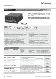
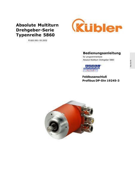
<strong>Absolute</strong> <strong>Multiturn</strong><br />
<strong>Drehgeber</strong>-<strong>Serie</strong><br />
<strong>Typenreihe</strong> <strong>5860</strong><br />
R.600.083 / 05.2002<br />
Bedienungsanleitung<br />
für programmierbare<br />
Absolut <strong>Multiturn</strong> <strong>Drehgeber</strong> <strong>5860</strong><br />
Feldbusanschluß<br />
Profibus DP-Din 19245-3<br />
deutsch
© Fritz <strong>Kübler</strong> GmbH<br />
Diese Dokumentation unterliegt dem Urheberrechtschutz der Firma<br />
Fritz <strong>Kübler</strong> GmbH VS-Schwenningen. Sie darf ohne Zustimmung der<br />
Firma Fritz <strong>Kübler</strong> GmbH nicht abgeändert,erweitert noch vervielfältigt<br />
oder an Dritte weitergegeben werden.<br />
Fritz <strong>Kübler</strong> GmbH<br />
Zähl-und Sensortechnik<br />
Postfach 3440<br />
78050 VS-Schwenningen<br />
Tel. +49 (0)7720-3903-0<br />
Fax. +49-7720-21564<br />
Stand. 05.2002<br />
Technische Änderungen und Verbesserungen ,die dem Fortschritt unserer<br />
Produkte dienen, behalten wir uns vor.<br />
2<br />
deutsch
Inhalt<br />
Projektierung ................................... 4<br />
Montage-Demontage ......................... 4<br />
Grundlagen ..................................... 6<br />
Allgemeine Verdrahtungshinweise ........ 8<br />
Busanschluss ................................... 9<br />
Spannungsversorgung ..................... 10<br />
Busterminierung ............................. 10<br />
Adresseneinstellung ........................ 10<br />
Protokoll allgemein.......................... 11<br />
Profibus Implementierung ................. 12<br />
Profibus Encoder Funktionen ............. 13<br />
Technische Daten ............................ 14<br />
Abkürzungen ................................. 15<br />
Fritz <strong>Kübler</strong> GmbH Zähl-und Sensortechnik Programmieranleitung <strong>5860</strong> <strong>Serie</strong><br />
3<br />
deutsch
Projektierung<br />
Montage/Demontage<br />
Das Kapitel Projektierung enthält Informationen,die vorab für die Planung von Steuerungssystemen<br />
mit <strong>Absolute</strong>n <strong>Drehgeber</strong>n <strong>Serie</strong> <strong>5860</strong> notwendig sind.<br />
Diese Informationen reichen von Angaben über lieferbare Geberausführungen bis zum<br />
maximalen Systemausbau einer Profibus-DP Linie<br />
Befestigungsmöglichkeiten für <strong>Drehgeber</strong>:<br />
Befestigung mit einer Drehmomentstütze (Hohlwellengeber)<br />
Ein handelsüblicher Zylinderstift nach DIN 7 ∅ 4 mm, der mit der Maschine<br />
verbunden ist wir in die vorgesehene Nut des <strong>Drehgeber</strong>s eingeführt,<br />
um rotatorische Bewegungen des <strong>Drehgeber</strong>s durch Drehmomente,<br />
z.B. beim Anlaufen zu verhindern, radiale und axiale Bewegungen,<br />
z.B. durch Spiel des Antriebes auszugleichen.Der Zylinderstift<br />
ist Bestandteil des Befestigungssets Art. Nr<br />
Befestigung mit verlängerter Drehmomentstütze (Hohlwellengeber)<br />
Die verlängerte Drehmomentstütze ist ebenfalls Bestandteil des<br />
Befestigungssets<br />
Beachten Sie die Sicherheitshinweise auf dem Faltblatt des <strong>Drehgeber</strong>s!<br />
Fritz <strong>Kübler</strong> GmbH Zähl-und Sensortechnik Programmieranleitung <strong>5860</strong> <strong>Serie</strong><br />
4<br />
deutsch
Befestigung mit der Statorkupplung (Hohlwellengeber)<br />
Statorkupplung: <strong>Kübler</strong> Art. Nr.: 8.0010.1601.0000<br />
Diese Art der Montage ist die optimale, wenn auch teuerste<br />
Montage mit einer Montageglocke+Kupplung (vor allem Wellengeber)<br />
Dies ermöglicht eine thermische und elektrische Trennung von Antrieb<br />
und <strong>Drehgeber</strong>. Art. Nr. 8.0000.4500.XXXX<br />
Montage mit einer Lagerbox (Wellengeber)<br />
Diese sollte vor allem dann zum Einsatz kommen, wenn mit axialen und<br />
radialen Wellenbelastungen zu rechnen ist, die die im Datenblatt angegebenen<br />
Werte überschreiten.<br />
Art. Nr. 8.0010.8200.0004<br />
5<br />
deutsch
Grundlagen PROFIBUS-DP<br />
In dieser Beschreibung ist die Implementation des Übertragungsprotokolls<br />
PROFIBUS-DP im Slavemodus auf unseren Geräten dokumentiert.<br />
Dabei ist zu beachten, daß der beschriebene Funktionsumfang<br />
je nach Gerät oder Einsatzfall eingeschränkt sein kann. Insbesondere<br />
bei Protokollkonvertierungen wird in der Regel ein geringerer<br />
Funktionsumfang genutzt!<br />
1.1 Das Anforderungsprofil<br />
Die Verbindung zwischen dem dezentralen Prozeßablauf und der zentralen<br />
Steuerung über das Kommunikationssystem erfolgt in der untersten<br />
Hierarchiestufe über den Feld- oder Prozeßbus. In dieser Stufe<br />
gilt als Anforderung in erster Linie ein einfacher Protokollablauf und<br />
kurze Datenübertragungszeiten bei der Kommunikation. Dies garantiert<br />
die möglichst kurze Systemreaktionszeit auf die dynamischen<br />
Peripheriezustände. Neben dem klassischen E/A-Datenaustausch muß<br />
eine azyklische Übertragung von Parameter-, Diagnose- und<br />
Konfigurationsdaten möglich sein, ohne die Echtzeittauglichkeit des<br />
Busses entscheident zu behindern. Nur so kann ein gutes Diagnosekonzept<br />
erfüllt und die Betriebssicherheit gewährleistet werden.<br />
1.2 Eigenschaften<br />
Die Hauptaufgabe des PROFIBUS-DP ist die zyklische Übertragung der<br />
Prozeßdaten vom Steuerungssystem zu den Peripheriegeräten und<br />
umgekehrt. Dabei geschieht das Zugriffsverfahren nach dem Master-<br />
Slave-Prinzip. Ein Master bedient dabei im Polling-Betrieb nacheinander<br />
die ihm zugeordneten Slavegeräte am Bus. Ein Datenaustausch<br />
wird durch ein Aufruf-Telegramm eingeleitet und durch ein Quittungstelegramm<br />
des angesprochenen Slaves beendet. Jeder Slave wird also<br />
nur nach Aufforderung des Masters aktiv. Ein gleichzeitiger Buszugriff<br />
wird somit vermieden.Das hybride Zugriffsverfahren des PROFIBUS<br />
erlaubt einen Kombinationsbetrieb von mehreren Busmastern und sogar<br />
Mischbetrieb von PROFIBUS-DP und PROFIBUS-FMS innerhalb eines<br />
Busabschnitts. Voraussetzung ist hierbei aber die richtige<br />
Konfigurierung des Bussystems und die eindeutige Zuordnung der<br />
Slavegeräte zu den Mastern. Der PROFIBUS-DP unterscheidet zwei<br />
Arten von Mastern. Der Master Klasse 1 führt die zyklische Nutzdatenübertragung<br />
durch und stellt die Anwenderdaten. Der Master<br />
Klasse 1 kann von einem Master Klasse 2 mit bestimmten Funktionen<br />
angesprochen werden. Ein direkter Zugriff auf Slaves ist nicht erlaubt.<br />
Die Funktionen beschränken sich dabei auf Support-Dienste wie z.B.<br />
das Auslesen der Diagnoseinformationen von Slaves. Ein Master Klasse<br />
2 wird daher auch als Programmier- oder Diagnosegerät verstanden.<br />
6<br />
deutsch
1.3 Schutzfunktionen<br />
Der PROFIBUS-DP ist mit zahlreichen Schutzfunktionen ausgestattet. Sie<br />
gewährleisten die sichere Kommunikation gerade in der rauhen Umgebung<br />
der dezentralen Peripherie nicht nur im fehlerfreien Betrieb, sondern<br />
auch bei ex-ternen Störeinflüssen oder Ausfällen von Teilnehmern.<br />
Eine Fehlparametrierung wird direkt erkannt, indem Teilnehmer mit fehlerhaften<br />
Parametern nicht in den Nutzdatenbetrieb aufgenommen werden.<br />
Der Ausfall von Teilnehmern wird masterseitig registriert und dem Anwender<br />
über Sammeldiagnose angezeigt.<br />
Der Ausfall der Übertragungsstrecke wird durch eine Zeitüberwachung<br />
slavesseitig erkannt und führt zum Abschalten der Ausgänge.<br />
EMV-Störung werden durch das besonders störsichere Übertragungsverfahren<br />
nach RS485 über das Differenzsignal nahezu ausgefiltert.<br />
Datenübertragungsfehler werden durch Rahmen- und Checksummenprüfungen<br />
erkannt und führen zur Telegrammwiederholung.<br />
1.4 Inbetriebnahme<br />
Bevor ein PROFIBUS-DP-System in Betrieb genommen werden kann,<br />
müssen alle angeschlossenen Teilnehmer einschließlich dem Mastersystem<br />
eindeutige Busadressen erhalten. Nur so kann die eindeutige<br />
Adressierung am Bus erfolgen.Optional können die Adressen auch über<br />
den Bus vergeben werden.<br />
Über den Master-Parametersatz werden die physikalischen Systemeinstellungen<br />
vorgenommen. Er enthält neben der Master-Busadresse, z.B.<br />
die Baudrate, die Timeout-Zeiten und die Anzahl der Sendewiederholungen.<br />
Neben dem Master-Parametersatz muß für jeden zu<br />
aktiverenden Slave ein Slave-Datensatz abgelegt werden. Ein Datensatz<br />
enthält die Parametrierungs- und Konfigurationsdaten des Slaves und die<br />
Adreßzeiger für die logische Ablage der E/A-Daten.<br />
Sind die Parametersätze vorhanden, beginnt das Mastersystem nach<br />
Auffor-derung des Anwenders oder automatisch die Slaves nacheinander<br />
in Betrieb zu nehmen. Schon die ersten sogenannten Diagnosezyklen zeigen,<br />
welcher Slave am Bus vorhanden ist. Nur diejenigen Slaves, die sich<br />
im Diagnosezyklus korrekt zurückgemeldet haben, werden anschließend<br />
in Parameterzyklen mit den jeweiligen im Master abgelegten Daten<br />
parametriert. Bei fehlerfreier Durchführung folgt anschließend über<br />
Konfigurationszyklen der Vergleich der Master-Soll-Konfigurationsdaten<br />
und den Slave-Ist-Konfigurationsdaten. Nach dem letzten<br />
Diagnosezyklus ist jeder Slave betriebsbereit, der keinen Fehler beim<br />
Vergleich festgestellt hat. Jeder dieser Slave wird dann automatisch vom<br />
Master in den Nutzdatentransfer übernommen.<br />
Zur Diagnose hält der Master für jeden Slave einen Diagnosepuffer bereit,<br />
der an-wenderseitig ausgelesen werden kann. Zur vereinfachten<br />
Diagnose wird gleichzeitig ein Sammeldiagnosefeld geführt, in dem Bitweise<br />
angezeigt wird, ob ein Slave Diagnosedaten bereit hält oder nicht.<br />
7<br />
deutsch
Allgemeine Verdrahtungshinweise<br />
1. Installationshinweise für RS-485<br />
Alle Geräte werden in einer Busstruktur (Linie) angeschlossen. In einem<br />
Segment können bis zu 32 Teilnehmer (Master oder Slaves)<br />
zusammengeschaltet werden. Am Anfang und am Ende jedes Segments<br />
wird der Bus durch einen aktiven Busabschluß abgeschlossen Für einen<br />
störungsfreien Betrieb muß sichergestellt werden, daß die beiden Busabschlüsse<br />
immer mit Spannung versorgt werden. Der Busabschluß ist<br />
zuschaltbar in den Gerät bzw. dem Stecker realisiert.<br />
Bei mehr als 32 Teilnehmern müssen Repeater (Leistungsverstärker)<br />
eingesetzt werden, um die einzelnen Bussegmente zu verbinden.<br />
Die max. Leitungslänge ist abhängig von der Übertragungsgeschwindigkeit,<br />
siehe Tabelle 2.<br />
Die angegebene Leitungslänge kann durch den Einsatz von Repeatern<br />
vergrößert werden. Es wird empfohlen,<br />
nicht mehr als 3 Repeater in <strong>Serie</strong> zu schalten.<br />
Baudrate (kBit/s) 9,6 19,2 93,75 187,5 500 1500 12000<br />
Reichweite/Segment 1.200 m 1.200 m 1.200 m 1.000 m 400 m 200 m 100 m<br />
Tabelle 2 : Reichweite in Abhängigkeit der Übertragungsgeschwindigkeit<br />
für Kabeltyp A<br />
Schirmung - ja oder nein ?<br />
EN 50 170 überläßt es dem Anwender, ob geschirmtes oder<br />
ungeschirmtes Kabel eingesetzt werden soll. In störfreier Umgebung ist<br />
ungeschirmtes Kabel zugelassen. Folgende Gründe sprechen dafür, immer<br />
geschirmtes Kabel einzusetzen:<br />
a) Ein störungsfreier Raum existiert höchstens im Inneren von<br />
schirmenden Schaltschränken. Aber sobald sich<br />
darin auch Relais befinden, ist dies nicht mehr gewährleistet.<br />
b) Die Verwendung ungeschirmter Kabel verlangt nach zusätzlichen<br />
Schutzmaßnahmen an den Bussignal-Eingängen gegen Überspannungen.<br />
Deshalb wird grundsätzlich empfohlen für das Buskabel geschirmte Leitungen<br />
zu verwenden.Diese Empfehlung erstreckt sich auch auf eventuell<br />
benötigte Versorgungskabel von externen<br />
Spannungsversorgungen zu den PROFIBUS-Geräten z. B. für<br />
Repeater.Doppelt geschirmte Leitungen eignen sich besonders für stark<br />
EMV belastete Umgebungen. Um einen optimalen<br />
Schutz zu gewährleisten, muß in diesem Fall der äußere (Geflechtschirm)<br />
und der innere Schirm (Folienschirm)<br />
an beiden Kabelenden flächig mit einer Erdungsschelle auf Schutzerde<br />
aufgelegt werden.<br />
Schirmungs - Regeln<br />
Bei Verwendung eines geschirmten Buskabels wird empfohlen, den<br />
Schirm beidseitig niederinduktiv mit der Schutzerde zu verbinden. Dadurch<br />
wird eine möglichst optimale EMV erreicht. Eine Ausnahme betrifft<br />
getrennte Potentiale (z. B. in Raffinerien), hier ist in der Regel nur<br />
eine einseitige Erdung zulässig.<br />
Vorzugsweise wird die Verbindung zwischen dem Kabelschirm und der<br />
Schutzerde über ein metallisches Gerätegehäuse und den Schraubverschluß<br />
des Steckverbinder durchgeführt. Hierbei ist zu beachten, daß<br />
8<br />
Fritz <strong>Kübler</strong> GmbH Zähl-und Sensortechnik Programmieranleitung <strong>5860</strong> <strong>Serie</strong><br />
deutsch
Busanschluß<br />
die Ableitung über den Stift keine optimale Lösung darstellt. Im Sinne<br />
einer optimalen EMV ist es besser, den Kabelschirm an einer geeigneten<br />
Stelle freizulegen und mit einer möglichst kurzen niederinduktiven<br />
Kabelverbindung an Schutzerde (z. B. an das metallische Schaltschrankgehäuse)<br />
anzuschließen. Dies kann z. B. mit einer Schirmschelle<br />
vor dem Busstecker erfolgen.<br />
PROFIBUS - DP Kabel Richtlinie zum Anschluß der Abschirmung<br />
Installation und Einstellungen<br />
Für sämtliche Einstellungen und zum Anschließen<br />
des Gebers an das Profibus-System und an die<br />
Spannungsversorgung sind die 3 Inbusschrauben<br />
am Interface-Teil (Rückseite) zu öffnen.<br />
Danach kann das Anschlußteil entnommen und<br />
vorort direkt mit dem Bussystem und der<br />
Spannungsversorgung verbunden werden. Es<br />
folgt die Einstellung für Geräteadresse,<br />
Übertragungsrate und eventuell ist der Busabschluß<br />
zu aktivieren, falls der Geber das letzte<br />
Gerät in der Buskette darstellt. Abschließend muß<br />
das Anschlußteil mit dem Geberteil wieder verschraubt<br />
werden. Der Geber ist nun einsatzbereit.<br />
Nach Abnahme des Anschlußteils ist das Busanschlußteil<br />
sichtbar. Die Bezeichnung A-Line und<br />
B-Line ist zweimal vorhanden,das bedeutet,daß<br />
der PROFIBUS intern durchgeschleift wird.<br />
Hierfür sind auf der Leiterplatte schon entsprechende<br />
Verbindungen vorgesehen. Ist der <strong>Drehgeber</strong><br />
der letzte Teilnehmer am Bus, so muß<br />
die Busterminierung aktiviert werden.<br />
Fritz <strong>Kübler</strong> GmbH Zähl-und Sensortechnik Programmieranleitung <strong>5860</strong> <strong>Serie</strong><br />
9<br />
deutsch
Spannungsversorgung<br />
Busterminierung<br />
PIN-Nummer Funktion<br />
PIN 1 Spannungsversorgung +10..30 VDC<br />
PIN 2 Spannungsversorgung GND<br />
PIN 3 PROFIBUS GND<br />
PIN 4 Input PROFIBUS B-Line (PROFIBUS_H)<br />
PIN 5 Input PROFIBUS A-Line (PROFIBUS_L)<br />
PIN 6 Output PROFIBUS A-Line (PROFIBUS_L)<br />
PIN 7 Output PROFIBUS B-Line (PROFIBUS_H)<br />
PIN 8 PROFIBUS GND<br />
PIN 9 Spannungsversorgung GND<br />
PIN 10 Spannungsversorgung +10..30 VDC<br />
Hinweis:<br />
Die beiden Signaladern PROFIBUS_L und PROFIBUS_H dürfen nicht vertauscht<br />
werden - Bitte allgemeine Schirmungshinweise s.o. beachten<br />
Nach Abnahme des Anschlußteils ist das Busanschlußteil sichtbar. Die<br />
Bezeichnung +VDC und GND (1,2,9,10) bedeutet,daß auch die<br />
Spannungsversorgung intern durchgeschleift wird. Hierfür sind auf der<br />
Leiterplatte die entsprechenden Verbindungen vorgesehen.<br />
PIN-Nummer Funktion<br />
PIN 1 Spannungsversorgung +10..30 VDC<br />
PIN 2 Spannungsversorgung GND<br />
PIN 3 PROFIBUS GND<br />
PIN 4 Input PROFIBUS B-Line (PROFIBUS_H)<br />
PIN 5 Input PROFIBUS A-Line (PROFIBUS_L)<br />
PIN 6 Output PROFIBUS A-Line (PROFIBUS_L)<br />
PIN 7 Output PROFIBUS B-Line (PROFIBUS_H)<br />
PIN 8 PROFIBUS GND<br />
PIN 9 Spannungsversorgung GND<br />
PIN 10 Spannungsversorgung +10..30 VDC<br />
Schalter Busterminierung ein S2 (5+6)<br />
Schalter S2-5/6<br />
Im allgemeinen setzt die PROFIBUS-Norm ISO<br />
11898 eine Linienstruktur als Netzwerktopologie<br />
voraus.Die Linie wird an beiden Enden mit einem<br />
Abschlußwiderstand versehen. Dazu kann es notwendig<br />
sein, diese Terminierung zu aktivieren,<br />
wenn das Gerät als letzter Teilnehmer geschaltet<br />
werden muß. Hierzu wird intern im <strong>Drehgeber</strong><br />
ein Busabschlußwiderstand von 220 Ω zwischen<br />
die Leitungen PROFIBUS-Low und PROFIBUS-<br />
High geschaltet.<br />
Fritz <strong>Kübler</strong> GmbH Zähl-und Sensortechnik Programmieranleitung <strong>5860</strong> <strong>Serie</strong><br />
10<br />
deutsch
PROFIBUS Protokoll<br />
Geräteadresse S1 (1-6) + S2 (1)<br />
S1.1= LSB<br />
S2.1= MSB<br />
Die eingestellte Knoten-ID wird nach dem Anlegen<br />
der Versorgungsspannung während der<br />
Initialisierung des PROFIBUS-Gebers ausgelesen<br />
und gespeichert.<br />
Die Knoten-ID kann im Bereich zwischen 0...126<br />
eingestellt werden. Sie wird als Binärwert angegeben.<br />
Den Teilnehmern am PROFIBUS-Bus können<br />
maximal 128 Knoten-ID’s zugeordnet werden<br />
Beispiel: Adresse 63 S1-1 bis S1-6 on S2-1 off<br />
Die Adresse S1(1) ist das niederwertigste Bit.<br />
Bei S1(1-6) auf on ist die Geräteadresse 63<br />
eingestellt.<br />
Dies ist die Default-Einstellung, wenn das Gerät<br />
ausgeliefert wird.<br />
Hinweis:<br />
Jede Knoten-ID darf nur einmal vergeben werden!<br />
Knoten–ID 0 ist nicht zulässig und wird<br />
anhand der Software auf 1 eingestellt.<br />
Knotenadressen > 126 werden wieder auf 1<br />
gestellt !<br />
ISO/OSI-Schicht 1 und 2<br />
Die unteren Schichten nach dem OSI-Modell werden durch<br />
die Norm ISO 11898 definiert.Ergänzend durch den Profibus<br />
Standard gilt die Normierung für Steckverbinder und unterstützte<br />
Bitraten.<br />
Schicht 7 (Protokollschicht)<br />
Für die höheren Schichten (Schicht 7 ) wurde in einer Organisation<br />
von mehreren Encoderherstellern und der PNO ein<br />
Geräteprofil entwickelt und zum Standard erklärt. PROFI-<br />
BUS besteht aus einer Profilfamilie, basierend auf einem<br />
Kommunikationsteil und mehreren spezifischen Geräteteilen.<br />
Fritz <strong>Kübler</strong> GmbH Zähl-und Sensortechnik Programmieranleitung <strong>5860</strong> <strong>Serie</strong><br />
11<br />
deutsch
LED grün<br />
Profibus LED Status:<br />
LED rot<br />
Spannungsversorgung<br />
ein Gerät nicht konfiguriert<br />
aus Geräte Konfiguration<br />
übernommen, Datenaustausch<br />
vorhanden<br />
LED grün<br />
LED rot<br />
ein Gerät Spannungsversorgung und<br />
Busspannung ok<br />
aus keine Spannungsversorgung<br />
Spannungsversorgung muß über<br />
prüft werden.<br />
12<br />
deutsch
PROFIBUS Implementierung<br />
Ident-Nummer<br />
PROFIBUS Voreinstellungen<br />
Jeder DP-Slave und jeder DP-Master Klasse 1 muß eine Ident-Nummer<br />
haben (06AEHEX). Sie wird benötigt, damit ein Master ohne signifikanten<br />
Protokoll-Overhead die Typen der angeschlossenen Geräte identifizieren<br />
kann. Der Master vergleicht die Ident-Nummer der angeschlossenen<br />
DP-Geräte mit den Ident-Nummern in den vom<br />
Projektierungstool vorgegebenen Projektierungsdaten. Der Nutzdatentransfer<br />
wird nur dann begonnen, wenn die richtigen Geräte-Typen mit<br />
den richtigen Stationsadressen am Bus angeschlossen wurden. Dadurch<br />
wird eine hohe Sicherheit gegenüber Projektierungsfehlern erreicht.<br />
<strong>Kübler</strong> spezifische Voreinstellungen<br />
Einstellung der<br />
Übertragungsrate<br />
Einstellung der<br />
Knotenadresse<br />
Parametrierung<br />
Die Übertragungsrate des Gerätes wird per Software<br />
eingestellt und wird üblicherweise vom<br />
Mastersystem vergeben. Alle Module innerhalb<br />
eines PROFIBUS Netzwerkes müssen auf die gleiche<br />
Übertragungsrate eingestellt werden.<br />
Mit Hilfe der DIL-Schalter kann die Knotenadresse<br />
(Knoten-ID) des Encoders geändert werden. Diese<br />
Knoten-ID kann Werte zwischen 1..127 einnehmen.<br />
Die Default-Knoten-ID des Gerätes ist auf 32<br />
eingestellt.<br />
Defaultmodul Class2 <strong>Multiturn</strong> uP13, Class2 disabled,<br />
Scaling disabled, 25 Bit Resolution<br />
Fritz <strong>Kübler</strong> GmbH Zähl-und Sensortechnik Programmieranleitung <strong>5860</strong> <strong>Serie</strong><br />
13<br />
deutsch
2 Eigenschaften des <strong>Multiturn</strong> Encoders am Profibus<br />
2.1 PNO-Ident-Nummer<br />
Der Encoder hat die PNO-Ident-Nummer 06AE (Hex). Diese Nummer ist bei der PNO hinterlegt.<br />
2.2 Startphase des Encoders am PROFIBUS<br />
Beim Anlauf des Encoders befindet sich dieser im Zustand ‘Baud-Search’. Nach<br />
Erkennen der Baudrate wechselt er in den Zustand WAIT_PRM und wartet auf die<br />
Parametrierdaten vom DP_Master. Die Parametrierung erfolgt automatisch im Anlauf<br />
des DP-Masters. Als Parameter werden dem Encoder die Zählrichtung und die<br />
Messlänge in Schritten übertragen (Nähere Einzelheiten siehe Encoder-Profil der<br />
PNO). Der Encoder wechselt nach erfolgreicher Übertragung korrekter<br />
Parametrierdaten in den Zustand WAIT_CFG. Der PROFIBUS Master sendet dann<br />
ein Konfigurationsbyte um die Anzahl der Ein/Ausgänge festzulegen. Ist das<br />
Konfigurationsbyte korrekt, wechselt der Encoder in den Zustand DATA_EXCHANGE.<br />
2.3 Konfiguration und Parametrierung<br />
Die Parametrierung, d.h. Übergabe der Parameter für Zählrichtung, Auflösung des<br />
Encoders usw. erfolgt üblicherweise innerhalb des Konfigurationsprogramms für den<br />
verwendeten PROFIBUS-Master. Hierzu ist die Typdatei, bzw. Gerätestammdatei des<br />
Encoders in das jeweilige Verzeichnis für Typdateien bzw. Gerätestammdateien zu<br />
kopieren. Bei einigen Programmen, wie z.B. COM PROFIBUS oder STEP7 Manager,<br />
muß dann innerhalb der Software eine Aktualisierung der internen Geräteliste<br />
(Hardware-Katalog) ausgeführt werden. Nähere Informationen zur Einbindung von<br />
Feldgeräten entnehmen Sie bitte der Dokumentation der von Ihnen verwendeten<br />
Software.<br />
Zur Einbindung und Parametrierung des Encoders in ein Mastersystem sind innerhalb<br />
des Konfigurationsprogramms üblicherweise die zwei nachfolgend beschriebenen<br />
Schritte notwendig.<br />
2.3.1 Konfiguration<br />
Zur Konfiguration, d.h. Eingabe der Länge und des E/A-Typs auf dem PROFIBUS<br />
stellt das Konfigurationsprogramm üblicherweise eine Eingabemaske zur Verfügung,<br />
in der abhängig von der Soll-Konfiguration die Kennung normalerweise voreingestellt<br />
ist, so daß nur noch die E/A Adressen eingetragen werden müssen.<br />
Abhängig von der gewünschten Soll-Konfiguration belegt der Encoder auf dem<br />
PROFIBUS eine unterschiedliche Anzahl Eingangs- und Ausgangsworte.<br />
Die nachfolgend beschriebenen Parameter sind ebenfalls von der Sollkonfiguration<br />
abhängig.<br />
Die Gerätestammdatei KUEB06AE.GSD beinhaltet fünf Sollkonfigurationen für PNO Class1<br />
und 2 jeweils mit 16- und 32 Bit Auflösung.<br />
Im folgenden werden die einzelnen Soll Konfigurationen, und die Lage der<br />
Kommunikationsbytes für den Datenaustausch mit dem PROFIBUS-DP Master<br />
beschrieben.<br />
14<br />
deutsch
2.3.2 Parametrierung<br />
Zur Parametrierung, d.h. Eingabe der Daten für Auflösung, Zählrichtung, usw. stellt<br />
das Konfigurationsprogramm üblicherweise eine Eingabemaske zur Verfügung. Über<br />
diese Eingabemaske können nachfolgend beschriebene Parameter eingestellt<br />
werden.<br />
Code sequence (Zählrichtung):<br />
Legt die Zählrichtung des Encoders fest.<br />
Auswahl<br />
Class 2 functionality (Klasse 2 Funktionen):<br />
Legt den Funktionsumfang des Encoders fest.<br />
Klasse 2 ausgeschaltet bedeutet, im Encoder sind nur die Klasse 1 Funktionen aktiv,<br />
er skaliert den Positionswert nicht, und er ist nicht justierbar.<br />
Diagnostic:<br />
Um die erweiterte Diagnose aufzurufen,ist das Modul „Check Diag 0x33“ zu laden.Es werden<br />
erweiterte Diagnoseinformatonen an den Master übertragen. Die Auswertung ist dem Encoder<br />
profil zu entnehmen.<br />
Scaling function control (Skalierungsfunktion):<br />
Legt fest, ob der Encoder die Position nach Maßgabe der nachfolgenden Parameter<br />
skaliert. Ist Klasse 2 ausgeschaltet skaliert er den Positionswert nicht, und er ist nicht<br />
justierbar.<br />
2.4 Preseteinstellung<br />
Der Encoder kann im Modus ‘Class 2’ über den PROFIBUS im Wertebereich von<br />
24 Bit bzw. 15 Bit auf einen beliebigen Positionswert justiert werden.<br />
Dies geschieht durch Setzen des höchstwertigen Bits der Ausgangsdaten (231 bei<br />
Konfiguration Class 2 - 32 Bit bzw. 215 bei Konfiguration Class 2 - 16 Bit).<br />
Der in den Datenbytes 0 - 3 übertragene Presetjustagewert wird mit der steigenden<br />
Flanke des Bit 32 (=Bit 7 des Datenbytes 3) als Positionswert übernommen. Der<br />
Encoder zählt dann ab dieser Position weiter. Eine erneute Justage ist erst möglich<br />
nachdem das Steuerbit wieder zurückgesetzt wurde.<br />
Es erfolgt keine Quittierung des Vorgangs über die Eingänge.<br />
15<br />
deutsch
Class 1 16-Bit resolution, Kennung D0 (HEX):<br />
der Encoder verwendet nur 1 Eingangswort das über den Bus konsistent übertragen<br />
wird.<br />
Class 1 32-Bit resolution, Kennung D1 (HEX):<br />
der Encoder verwendet nur 2 Eingangsworte die über den Bus konsistent übertragen<br />
werden.<br />
Class 2 16-Bit resolution, Kennung F0 (HEX):<br />
der Encoder verwendet 1 Eingangswort und 1 Ausgangswort die über den Bus jeweils<br />
konsistent übertragen werden.<br />
Class 2 32-Bit resolution, Kennung F1 (HEX):<br />
der Encoder verwendet 2 Eingangsworte und 2 Ausgangsworte die über den Bus<br />
jeweils konsistent übertragen werden.<br />
Eingangsdoppelwort ED x<br />
16<br />
deutsch
PROFIBUS Encoder Funktionen<br />
Erweiterte Diagnose<br />
1. Geräteprofil für Encoder<br />
2. Class 1 zwingend für alle DP Encoder<br />
Funktion Octet Nr. Data Type Name<br />
Data_Exchange 1-4 Unsigned 32Position Value (input)<br />
Data_Exchange 1-4 Unsigned 32Preset Value (output)<br />
RD_inp 1-4 Unsigned 32Position Value<br />
Slave_Diag 7 Octet String External Diagnose Header<br />
Slave_Diag 8 Octet String Alarms<br />
Slave_Diag 9 Octet String Operating Status<br />
Slave_Diag 10 Octet String Encoder Type<br />
Slave_Diag 11-14 Unsigned 32Singleturn Resolution<br />
Slave_Diag 15,16 Unsigned 16Number of Revolution<br />
Set_prm 9 Octet String Operating Parameters<br />
3. Class 2 Optionale Funktionalität<br />
Funktion Octet Nr. Data Type Name<br />
Slave_Diag 17 Octet String Addtitional Alarms<br />
Slave_Diag 18,19 Octet String Supported Alarms<br />
Slave_Diag 20,21 Octet String Warnings<br />
Slave_Diag 22,23 Octet String Supported Warnings<br />
Slave_Diag 24,25 Octet String Profile Version<br />
Slave_Diag 26,27 Octet String Software Version<br />
Slave_Diag 28-31 Unsigned 32Operting Time<br />
Slave_Diag 32-35 Signed 32 Offset Value<br />
Slave_Diag 36-39 Signed 32 Manufacturer Offset Value<br />
Slave_Diag 40-43 Unsigned 32Measuring Units per Revolution<br />
Slave_Diag 44-47 Unsigned 32Total measuring range in measuring units<br />
Slave_Diag 48-57 ASCII StringSerial Number<br />
Set_prm 10-13 Unsigned 32Measuring Units per revolution<br />
Set_prm 14-17 Unsigned 32Total measuring range in measuring units<br />
Fritz <strong>Kübler</strong> GmbH Zähl-und Sensortechnik Programmieranleitung <strong>5860</strong> <strong>Serie</strong><br />
17<br />
deutsch
Technische Daten<br />
Mechanische Kennwerte:<br />
Bauform: rund, mit axialer Anbaufläche für<br />
Interface<br />
Außendurchmesser: max. 60 mm<br />
Gesamtlänge: max. 80 mm<br />
Welleninnendurchmesser: 10 mm<br />
Drehzahl: min. 1500 U/min (bei IP 65)<br />
Schutzart nach EN60529: IP65<br />
Arbeitstemberaturbereich: min. -10° C bis +80° C<br />
erweitert: -40° C bis +105° C<br />
Schockfestigkeit nach<br />
DIN-IEC 68-2-27: 1000 m / s² , 6 ms<br />
Vibrationsfestigkeit nach<br />
DIN-IEC 68-2-6: 100 m / s² , 10...2000Hz<br />
Anschlußart: 9 mm PG-System für BUS und<br />
7 mm für Spannungsversorgung<br />
Elektrische Kennwerte:<br />
Geberschnitstelle: PROFIBUS 2.0B Standard<br />
Bus-Schnittstelle: PROFIBUS - DP Geräte Protokoll<br />
Auflösung: 25 Bit <strong>Multiturn</strong><br />
13 Bit Singleturn<br />
Versorgungsspannung: 10-30 VDC<br />
Protokolle: PROFIBUS DP DIN 19245-3<br />
Profile for Encoder V 1.0<br />
Zubehör: CD-Rom mit Manual und<br />
GSD-Datei<br />
18<br />
deutsch
Abkürzungen<br />
ASIC Application specific integrated circuit (Applikationsspezifischer integrierter<br />
Schaltkreis)<br />
DP Dezentralized PeripheryDezentrale Peripherie<br />
DPM1 DP-Master (Klasse 1)Der DPM1 ist das zentrale Automatisierungsgerät bei<br />
PROFIBUS-DP<br />
DPM2 DP-Master (Klasse 2)Der DPM2 ist ein Projektierungs- oder Konfigurations-<br />
Gerät bei PROFIBUS-DP<br />
FDL Fieldbus Data LinkFDL ist die Bezeichnung der Datensicherungsschicht (2) bei<br />
PROFIBUS<br />
FMS Fieldbus Message SpecificationFMS definiert die Applikations-Dienste bei<br />
PROFIBUS-FMS<br />
GSD Geräte-Stamm-DatenElektronisches Gerätedatenblatt<br />
HMI Human Machine Interface (Mensch-Maschine-Schnittstelle)Bedien- und<br />
Beobachtungsgeräte<br />
KBL KommunikationsbeziehungslisteDie KBL beinhaltet die Liste aller<br />
Kommunikationsbeziehungen eines Teilnehmers<br />
KR Kommunikations ReferenzLokale Kurzbezeichnung für eine Kommunikationsbeziehung<br />
LLI Lower Layer InterfaceDas LLI ist ein Teil der Anwendungsschicht (7) bei PROFI-<br />
BUS-FMS<br />
MAC Medium Access ControlDie MAC bestimmt, wann ein Gerät das Recht erhält,<br />
Daten zu senden<br />
OV ObjektverzeichnisDas OV enthält die Beschreibung aller Kommunikationsobjekte<br />
eines Gerätes<br />
PA Process AutomationPA ist die PROFIBUS Variante für die Prozeßautomatisierung<br />
SAP Service Access PointDienstzugangspunkt in der PROFIBUS Schicht 2<br />
TSDI Station Delay Time InitiatorAufrufverzögerungszeit des Initiators<br />
TSDR Station Delay Time ResponderAntwortverzögerungszeit des Responders<br />
VFD Virtual Field Device (virtuelles Feldgerät)Das VFD ist der für die Kommunikation<br />
erreichbare Teil eines realen Gerätes<br />
Fritz <strong>Kübler</strong> GmbH Zähl-und Sensortechnik Programmieranleitung <strong>5860</strong> <strong>Serie</strong><br />
19<br />
deutsch
<strong>Absolute</strong> <strong>Multiturn</strong><br />
Encoder <strong>Serie</strong>s<br />
Type <strong>5860</strong><br />
R.600.083 / 05.2002<br />
Operating<br />
Instructions<br />
for programmable <strong>Absolute</strong> <strong>Multiturn</strong><br />
Shaft Encoder<br />
Field bus interface<br />
Profibus-DP DIN 19245-3<br />
english
© Fritz <strong>Kübler</strong> GmbH<br />
This documentation is protected by the copyright of Firma Fritz <strong>Kübler</strong><br />
GmbH VS-Schwenningen. It may neither be altered, extended, nor<br />
duplicated or transmitted to third parties without previous agreement of<br />
Firma Fritz <strong>Kübler</strong> GmbH.<br />
Fritz <strong>Kübler</strong> GmbH<br />
Zähl-und Sensortechnik<br />
Postfach 3440<br />
78050 VS-Schwenningen<br />
Phone +49(0)7720-3903-0<br />
Fax +49-7720-21564<br />
Version 05.2002<br />
We reserve the right to make any technical modification or improvement<br />
required for the progress of our products.<br />
2<br />
english
Summary<br />
Project ........................................... 4<br />
Assembly-Disassembly ........................ 4<br />
Basics............................................. 6<br />
General wiring instructions................... 8<br />
Bus connection ................................. 9<br />
Power supply.................................. 10<br />
Bus termination............................... 10<br />
Address setting .............................. 10<br />
Protocol in general .......................... 11<br />
Profibus implementation .................... 12<br />
Profibus encoder functions ................ 13<br />
Technical data ................................ 14<br />
Abbreviations ................................. 15<br />
Fritz <strong>Kübler</strong> GmbH Zähl-und Sensortechnik Programming instructions <strong>5860</strong> <strong>Serie</strong>s<br />
3<br />
english
Project<br />
Assembly/Disassembly<br />
The chapter Project contains information that is required when starting the design of<br />
control systems using <strong>Absolute</strong> Encoders 9080.<br />
This information ranges from indications about the available encoder versions up to<br />
the maximum system extension of a Profibus line.<br />
Mounting possibilities for encoders:<br />
Mounting with a pin and the location slot (Hollow shaft encoders)<br />
A standard cylindrical pin ∅ 4 mm according to DIN 7, mounted on the<br />
machine, is introduced in the location slot provided on the encoder in<br />
order to prevent the rotation of the encoder due to torque, e. g. when<br />
the drive starts rotating, and to compensate radial and axial moves,<br />
e. g. due to the play of the drive. The cylindrical pin is a part of the<br />
mounting set, Art. No.<br />
Mounting with a long location slot (Hollow shaft encoders)<br />
The long location slot is also a part of the mounting set.<br />
Adhere to the safety instructions on the instruction sheet of the encoder!<br />
Fritz <strong>Kübler</strong> GmbH Zähl-und Sensortechnik Programming instructions <strong>5860</strong> <strong>Serie</strong>s<br />
4<br />
english
Mounting with the stator coupling (Hollow shaft encoders)<br />
Stator coupling: <strong>Kübler</strong> Art. No.: 8.0010.1601.0000<br />
This is the optimal mounting type, even though it is the most expansive.<br />
Mounting with an assembly bell+coupling (Mainly shaft encoders)<br />
This mounting ensures thermic and electric insulation of the drive and<br />
the encoder. Art. No. 8.0000.4500.XXXX<br />
Mounting with a bearing box (Shaft encoders)<br />
This mounting is to be used mainly when axial and radial shaft loads are<br />
likely to appear, that exceed the values indicated in the specifications<br />
sheet of the encoder.<br />
Art. No. 8.0010.8200.0004<br />
5<br />
english
PROFIBUS-DP basics<br />
This description gives informations about the implementation of the<br />
PROFIBUS-DP transmission protocol in the slave mode in our devices. It<br />
has to be noted that the extent of the functions described may be<br />
limited according to the device or to the application. In particular in<br />
the case of protocol conversions, less functions are used in general!<br />
1.1 The profile required<br />
The link between the decentralized process course and the central<br />
control via the communication system takes place in the lowest<br />
hierarchy level on the field or process bus. At this level, the main<br />
requirements are a simple protocol operation and short data<br />
transmission times for the communication. This ensures the fastest<br />
system reaction time upon the dynamic states of the periphery. In<br />
addition to the classisc I/O data exchange, the acyclic transmission of<br />
parameter, diagnostic and configuration data must be possible, without<br />
impeding in a decisive way the real time ability of the bus. This is the<br />
only way to ensure a good diagnostic concept and the safe operation .<br />
1.2 Characteristics<br />
The main task of PROFIBUS-DP is the cyclic transmission of the<br />
process data from the control system to the peripheral equipment and<br />
vice versa. The access procedure uses the Master-Slave principle.<br />
With this principle, a Master serves in polling operation its assigned<br />
slave devices one after the other on the Bus. A data exchange is<br />
initiated by a calling telegram and ended by an acknowledgement<br />
telegram of the Slave concerned. So, each Slave only becomes active<br />
after a call from the Master. This avoids a simultaneous bus access.<br />
The hybrid access procedure of PROFIBUS allows a combined operation<br />
of several bus masters and even a mixed operation of PROFIBUS-DP<br />
and PROFIBUS-FMS within a bus section. However, the correct<br />
configuration of the bus system and the univocal assignment of the<br />
Slave devices to the Masters is the condition for this kind of operation.<br />
PROFIBUS-DP distinguishes two types of Masters. The Class 1 Master<br />
carries out the cyclic operating data transmission and supplies the user<br />
data. The Class 1 Master can be addressed by a Class 2 Master using<br />
certain functions. A direct access to Slaves is not allowed. The<br />
functions are limited to support services like e. g. the reading of the<br />
diagnostic information of Slaves. A Class 2 Master is thus also<br />
understood as a programming or diagnostic device.<br />
6<br />
english
1.3 Protective functions<br />
PROFIBUS-DP is equipped with many protective functions. These do not<br />
only ensure a safe communication in the rough environment of the<br />
decentralized peripheral equipment at the level of the good operation, but<br />
also in case of external disturbances or breakdown of bus members.<br />
Wrong parameter setting is recognized directly, by the fact that bus<br />
members with wrong parameters are not integrated in the operating data<br />
exchange.<br />
The Master records the breakdown of bus members and indicates it to the<br />
user by means of a general diagnostic message.<br />
The breakdown of the transmission line is detected by the slave by means<br />
of time monitoring and leads to the switching off of the outputs.<br />
EMC disturbances are almost filtered out by means of the difference signal<br />
thanks to the particularly interference-proof transmission process<br />
according to RS485.<br />
Data transmission errors are recognized thanks to frame and check-sum<br />
controls and lead to the repetition of the telegram.<br />
1.4 Start-up<br />
Before a PROFIBUS-DP System can be started up, univocal bus addresses<br />
must be assigned to all connected bus members, including the Master<br />
system. This is the only way to ensure an univocal addressing on the bus.<br />
As an option, the addresses can also be assigned via the bus.<br />
The physical system settings are made using the parameters set of the<br />
Master. This set includes, in addition to the bus address of the Master,<br />
e. g. the baud rate, the time-out delays and the number of repetitions of<br />
the transmission. In addition to the parameters set of the Master, a Slave<br />
data set must be saved for each Slave to be activated. A data set<br />
contains the parameterizing and configuration data of the Slave and the<br />
address indicator for the logical storage of the I/O data.<br />
When the parameter sets are defined, the Master system begins, upon<br />
instruction of the user or automatically, to start the Slaves up, one after<br />
the other. Already the first diagnostic cycles show which Slave is<br />
detected on the bus. Only the Slaves that sent a correct feedback during<br />
the diagnostic cycle will be parameterized during the following<br />
parameterizing cycles with the corresponding data stored in the Master.<br />
In case of correct execution, configuration cycles perform then a<br />
comparison between the required configuration data stored in the Master<br />
and the actual configuration data of the slave. After the last diagnostic<br />
cycle, each Slave for which no error was detected during the comparison<br />
is ready for operation. Each of these Slaves is then integrated<br />
automatically by the master in the operating data transfer.<br />
For diagnostic purposes, the Master provides a diagnostic buffer for each<br />
Slave, which can be read for other purposes. To simplify the diagnostics,<br />
a general diagnostic field is kept simultaneously, which shows, bit by bit,<br />
whether a Slave shows diagnostics data.<br />
7<br />
english
General wiring instructions<br />
1. Installation instructions for RS-485<br />
All devices are connected within a bus structure (line). Up to 32<br />
members (Master or Slaves) can be linked together in one segment. The<br />
bus is terminated at the beginning and at the end of each segment by<br />
an active bus termination. To ensure a disturbance-free operation, it<br />
must be made sure that both bus terminations always remain powered.<br />
The bus termination is provided ready-to-activate in the device or in<br />
the connector.<br />
In case of more than 32 bus members, repeaters must be inserted, to<br />
connect the various bus segments.<br />
The maximum line length depends on the transmission speed, refer to<br />
Table 2.<br />
The line length indicated can be increased using repeaters. It is<br />
recommended not to connect more than 3 repeaters serially.<br />
Baud rate (kBit/s) 9,6 19,2 93,75 187,5 500 1500 12000<br />
Range/segment 1.200 m 1.200 m 1.200 m 1.000 m 400 m 200 m 100 m<br />
Table 2: Range depending on the transmission speed for A-type cable.<br />
Shielding - yes or no ?<br />
EN 50 170 leaves it up to the user to decide whether to use shieded or<br />
unshielded cable. Unshielded cable is allowed in interference-free<br />
environments. However, the following reasons argue for the systematic<br />
use of shielded cable:<br />
a) An interference-free room in exists at the most inside shielding<br />
cabinets. But, as soon as such a cabinet contains also relays,<br />
this is not ensured any more.<br />
b) The use of unshielded cables requires additional protective<br />
measures against overvoltage at the bus signal inputs.<br />
This is why we recommend, as a principle, the use of shielded cables for<br />
the bus lines. This recommendation extends also to the possibly required<br />
power supply cables coming from external power sources to the<br />
PROFIBUS devices, e. g. for repeaters. Double-shielded lines suit<br />
particularly for environments with strong EMC interference. In this case,<br />
in order to ensure an optimal protection, the whole surface of the<br />
external shielding (plait) and of the internal shielding (film) must be<br />
connected at both cable ends by means of an earth clip with the<br />
protective earth.<br />
Shielding rules<br />
When using a shielded bus cable, it is recommended to connect the<br />
shield on both sides with a low-induction connection to the protective<br />
earth. This ensures the most optimal EMC possible. Separated potentials<br />
(e. g. in refineries) are an exception: generally, in these plants, earthing<br />
is allowed at one end only.<br />
The link between the cable shielding and the protective earth is carried<br />
out preferably by means of the metallic cabinet of a device and the<br />
screwed plug of the connector. Consider the fact that the derivation via<br />
the pin is not an optimal solution. To achieve an optimal EMC, it is<br />
better to set the cable shielding free at a suitable location and to<br />
connect it with the protective earth (e. g. the metallic cabinet frame)<br />
using a low-induction cable link as short as possible. This may be done<br />
e. g. with a shielding location before the bus plug.<br />
8<br />
Fritz <strong>Kübler</strong> GmbH Zähl-und Sensortechnik Programming instructions <strong>5860</strong> <strong>Serie</strong>s<br />
english
Cable specification - A-type cable for PROFIBUS - DP<br />
Bus connection<br />
Surge impedance: 135 to 165 Ohm, for a measurement frequency of<br />
3 to 20 MHz.<br />
Cable capacitance: < 30 pF per metre<br />
Conductor section: > 0,34 mm², corresponds to AWG 22<br />
Cable type: twisted pairs, 1 x 2 or 2 x 2 or 1 x 4<br />
conductors<br />
Loop resistance: < 110 Ohm per km<br />
Signal damping: max. 9 dB on the whole length of the line section<br />
Shielding: Copper plait shielding or plait shielding and film<br />
shielding<br />
Installation and settings<br />
The 3 hexagon socket screws of the interface<br />
section must be opened to perform any setting<br />
and to connect the encoder to the Profibus<br />
system and to the power supply.<br />
Then, the connection section may be removed and<br />
connected directly on site to the bus system and<br />
the power supply. After this, set the device<br />
address and the transmission speed and, if<br />
required, activate the bus termination, if the<br />
encoder is the last device in the bus chain.<br />
Finally, screw the connection section back onto<br />
the encoder section. The encoder is now ready to<br />
operate.<br />
The bus connection section can be found after<br />
dismounting the connection section. The<br />
designation A-Line and B-Line is provided<br />
twice; this indicates, that the PROFIBUS is<br />
looped internally. Corresponding terminals to<br />
that purpose are already provided on the<br />
printed circuit. If the encoder is the last<br />
member on the bus, the bus termination must<br />
be activated.<br />
Fritz <strong>Kübler</strong> GmbH Zähl-und Sensortechnik Programming instructions <strong>5860</strong> <strong>Serie</strong>s<br />
9<br />
english
Profibus connection PIN-Number Function<br />
Power supply<br />
Bus termination<br />
PIN 1 (bn) +UB 10..30 VDC<br />
PIN 2 (bl) 0 VDC<br />
PIN 3 PROFIBUS GND<br />
PIN 4 (rd) Input B-Line (PROFIBUS_H)<br />
PIN 5 (gn) Input A-Line (PROFIBUS_L)<br />
PIN 6 (gn) Output A-Line (PROFIBUS_L)<br />
PIN 7 (rd) Output B-Line (PROFIBUS_H)<br />
PIN 8 PROFIBUS GND<br />
PIN 9 (bl) 0 VDC<br />
PIN 10 (bn) +UB 10..30 VDC<br />
Note:<br />
The two signal lines PROFIBUS_L and PROFIBUS_H shall not be inverted -<br />
Please adhere to the above general shielding instructions<br />
The bus connection section can be found after dismounting the<br />
connection section and removing the two screws on the printed circuit.<br />
The designation +UB and 0 VDC (1,2,9,10) indicates that the power<br />
supply is also looped internally. The corresponding terminals to that<br />
purpose are provided on the printed circuit.<br />
Schalter S2-5/6<br />
PIN-Number Function<br />
PIN 1 (bn) +UB 10..30 VDC<br />
PIN 2 (bl) 0 VDC<br />
PIN 3 PROFIBUS GND<br />
PIN 4 (rt) Input B-Line (PROFIBUS_H)<br />
PIN 5 (gn) Input A-Line (PROFIBUS_L)<br />
PIN 6 (gn) Output A-Line (PROFIBUS_L)<br />
PIN 7 (rt) Output B-Line (PROFIBUS_H)<br />
PIN 8 PROFIBUS GND<br />
PIN 9 (bl) 0 VDC<br />
PIN 10 (bn) +UB 10..30 VDC<br />
Bus termination On switch S2 (5+6)<br />
In general, the PROFIBUS standard ISO 11898<br />
requires a network topology in the form of a line<br />
structure. The line is equipped at both ends with a<br />
terminal resistor. It may be necessary to activate<br />
this termination if the device must be connected<br />
as the last bus member. To that purpose, a<br />
220 Ω bus termination resistor is connected<br />
internally in the encoder, between the lines<br />
PROFIBUS-Low and PROFIBUS-High.<br />
Fritz <strong>Kübler</strong> GmbH Zähl-und Sensortechnik Programming instructions <strong>5860</strong> <strong>Serie</strong>s<br />
10<br />
english
Device address<br />
PROFIBUS Protocol<br />
Example: Address 63 S1-6 on S2.1 off<br />
Device address S1 (1-6) + S2 (1)<br />
S1.1 = LSB .... S2.1 = MSB<br />
The node ID set is read and stored after<br />
powering the device, during the initialization of<br />
the PROFIBUS encoder.<br />
The node ID can be set in the range between<br />
0...126. It is defined as a binary value. A<br />
maximum of 128 node ID‘s can be assigned to<br />
the members of the PROFIBUS bus.<br />
The address S1(1) is the least significant bit.<br />
When S1(1-6) is on, the device address 63 is<br />
set.<br />
This is the default setting when delivering the<br />
device.<br />
Note:<br />
Each node ID may only be assigned once!<br />
Node ID 0 is not allowed and is set to 1 by the<br />
software. Node address > 126 will be set to 1.<br />
ISO/OSI layer 1 and 2<br />
The lower layers according to the OSI model are defined by<br />
standard ISO 11898. In addition, the Profibus standard<br />
defines the standard for plug-in connectors and supported bit<br />
rates.<br />
Layer 7 (Protocol layer)<br />
For the higher layers (layer 7), an organisation of several<br />
encoder manufacturers and the PNO developed a device<br />
profile and declared it to be a standard. PROFIBUS is made<br />
up of a profiles family, based on a communications section<br />
and several specific device sections.<br />
Fritz <strong>Kübler</strong> GmbH Zähl-und Sensortechnik Programming instructions <strong>5860</strong> <strong>Serie</strong>s<br />
11<br />
english
LED green<br />
Profibus LED Status:<br />
red LED<br />
LED red<br />
on Device not configured<br />
off Device configuration taken into<br />
account, data exchange available<br />
green LED<br />
on Device power supply ok<br />
off No power supply<br />
Screws for dismounting<br />
12<br />
english
PROFIBUS implementation<br />
Ident Number<br />
PROFIBUS pre-settings<br />
Each DP Slave and each Class 1 DP Master must have an ident<br />
number (06AEHEX). It is required in oder to allow a Master to identify<br />
without significant protocol overhead the types of the devices<br />
connected. The Master compares the ident number of the connected DP<br />
devices with the ident numbers stored in the project data defined by<br />
the project tool. The operating data transfer only starts when the<br />
correct device types, with the correct station addresses, are<br />
connected to the bus. This allows a high safety level against project<br />
mistakes.<br />
<strong>Kübler</strong>-specific pre-settings<br />
Transmission rate<br />
setting<br />
Node address<br />
setting<br />
Configuration<br />
The transmission rate of the device is set by<br />
software and is normally assigned by the Master<br />
system. All modules within a PROFIBUS network<br />
must be set to the same transmission rate.<br />
The DIP switch allows changing the node address<br />
(node ID) of the encoder. This node ID can have<br />
values between 1..127.<br />
The default node ID of the device is set to 32.<br />
Default modul Class2 <strong>Multiturn</strong> uP13, Class2 disabled,<br />
Scaling disabled, 25 Bit Resolution<br />
Fritz <strong>Kübler</strong> GmbH Zähl-und Sensortechnik Programming instructions <strong>5860</strong> <strong>Serie</strong>s<br />
13<br />
english
PROFIBUS encoder functions<br />
1. Device profile for encoders<br />
2. Class 1 imperative for all DP encoders<br />
Function Octet No. Data Type Name<br />
Data_Exchange 1-4 Unsigned 32Position Value (input)<br />
Data_Exchange 1-4 Unsigned 32Preset Value (output)<br />
RD_inp 1-4 Unsigned 32Position Value<br />
Slave_Diag 7 Octet String External Diagnose Header<br />
Slave_Diag 8 Octet String Alarms<br />
Slave_Diag 9 Octet String Operating Status<br />
Slave_Diag 10 Octet String Encoder Type<br />
Slave_Diag 11-14 Unsigned 32Singleturn Resolution<br />
Slave_Diag 15,16 Unsigned 16Number of Revolution<br />
Set_prm 9 Octet String Operating Parameters<br />
3. Class 2 Optional functionality<br />
Function Octet No. Data Type Name<br />
Slave_Diag 17 Octet String Addtitional Alarms<br />
Slave_Diag 18,19 Octet String Supported Alarms<br />
Slave_Diag 20,21 Octet String Warnings<br />
Slave_Diag 22,23 Octet String Supported Warnings<br />
Slave_Diag 24,25 Octet String Profile Version<br />
Slave_Diag 26,27 Octet String Software Version<br />
Slave_Diag 28-31 Unsigned 32Operting Time<br />
Slave_Diag 32-35 Signed 32 Offset Value<br />
Slave_Diag 36-39 Signed 32 Manufacturer Offset Value<br />
Slave_Diag 40-43 Unsigned 32Measuring Units per Revolution<br />
Slave_Diag 44-47 Unsigned 32Total measuring range in measuring units<br />
Slave_Diag 48-57 ASCII String Serial Number<br />
Set_prm 10-13 Unsigned 32Measuring Units per revolution<br />
Set_prm 14-17 Unsigned 32Total measuring range in measuring units<br />
Fritz <strong>Kübler</strong> GmbH Zähl-und Sensortechnik Programming instructions <strong>5860</strong> <strong>Serie</strong>s<br />
14<br />
english
Technical data<br />
Mechanical features:<br />
Execution: round, with axial mounting surface for<br />
the interface<br />
External diameter: max. 60 mm<br />
Total length: max. 80 mm<br />
Shaft diameter: up to 12 mm<br />
Speed: min. 1500 RPM (for IP 65)<br />
Protection acc. to EN60529: IP65<br />
Operating temperature range: min. -20° C to +80° C<br />
extended: -40° C to +105° C<br />
Shock resistance acc. to<br />
DIN-IEC 68-2-27: 1000 m / s² , 6 ms<br />
Vibration resistance acc. to<br />
DIN-IEC 68-2-6: 100 m / s² , 10...2000Hz<br />
Connection type: 9 mm PG System for BUS connection<br />
and 7 mm for power supply<br />
Electrical features:<br />
Encoder interface:<br />
Bus interface: PROFIBUS 2.0B Standard<br />
PROFIBUS device protocol<br />
Resolution: 25 Bits <strong>Multiturn</strong><br />
13 Bits Singleturn<br />
Supply voltage: 10-30 VDC<br />
Protocols: PROFIBUS-DP DIN 19245-3<br />
Profile for Encoder<br />
Accessories: CD-Rom with Manual and<br />
GSD file<br />
15<br />
english