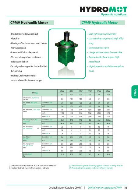
CPMV Hydraulik Motor CPMV Hydraulic Motor
CPMV Hydraulik Motor CPMV Hydraulic Motor
CPMV Hydraulik Motor CPMV Hydraulic Motor

Sie wollen auch ein ePaper? Erhöhen Sie die Reichweite Ihrer Titel.
YUMPU macht aus Druck-PDFs automatisch weboptimierte ePaper, die Google liebt.
<strong>Hydraulic</strong> solutions.AbtriebswellenOutput shaftsC - 0 50 mm zylindrisch mit Passfeder A14 x 9 x 70 (DIN 6885) / 0 50mmstraight, parallel key A14 x 9 x 70 (DIN 6885)SH - 0 21⁄8“ verzahnt, 16 DP 8/16 ANS B92.1-1976 / 0 21⁄8“ splined, 16 DP8/16 ANS B92.1-1976CO - 0 57.15 mm (21∕4“) zylindrisch mit Passfeder 1⁄2“ x 1⁄2“ x 2¼“ BS46.0 57.15 mm (21⁄4“) straight, parallel key 1⁄2“ x 1⁄2“ x 2¼“ BS46.K - kon. 1:10 mit Passfeder B16 x 10 x 32 DIN 6885 / conical 1:10, parallelkey B16 x 10 x 32 DIN 6885.<strong>CPMV</strong>BestellinformationenOrder Information1 2 3 4 5 6 7<strong>CPMV</strong>Pos. 1Leer / OmitWMontageflansch / Mounting flangeQuadratflansch 4-loch / Square flange 4-holesRadflansch / Wheel mountKSHKonisch 1:10 mit Passfeder B16 x 10 x 32Conical 1:10 with key B16 x 10 x 320 21⁄8“ verzahnt, 17 Zähne0 21⁄8“ splined, 17T.Pos. 2Schluckvolumen / Displacement315 315 cm³/U / 315 ccm/REV400 400 cm³/U / 400 ccm/REV500 500 cm³/U / 500 ccm/REV630 630 cm³/U / 630 ccm/REV800 800 cm³/U / 800 ccm/REV1000 1000 cm³/U / 1000 ccm/REVPos. 3CCOWellenausführungen / Shaft extensions0 50 mm zylindrisch mit Passfeder A14 x 8 x 700 50 mm straight, parallel key A14 x 8 x 70.0 57.15 mm (21⁄4“) zylindrisch mit Passfeder 1⁄2“ x 1⁄2“ x 2¼“0 57.15 mm (21⁄4“) zylindrisch mit Passfeder 1⁄2“ x 1⁄2“ x 2¼“Pos. 5Anschlüsse / PortingLeer / Omit G 1” / G 1”M Metrisch 2 x M33 x 2 / Metric 2 x M33 x 2UPos. 6Leer / Omit2 x 15⁄16”-12 UN, T: 9⁄16 - 18 UNF2 x 15⁄16”-12 UN, T: 9⁄16 - 18 UNFFarbe / PaintingGrau / GreyRAL... + Ralfarbe (z.B. 7021) / + Ral colour (e.g. 7021)lPos. 7Leer / OmitRDrehrichtung / Rotation directionStandarddrehrichtung / Standard RotationUmgekehrte Drehrichtung / Reverse Rotation60 Orbital <strong>Motor</strong> Katalog <strong>CPMV</strong> | Orbital motor catalogue <strong>CPMV</strong>
<strong>Hydraulic</strong> solutions.Berechnung von <strong>Hydraulik</strong>motorenAuslegung von Radantrieben:1. Antriebsdrehzahl n Radantriebsmotor:n 2, 65 v i kmR mv km= Geschwindigkeit des Fahrzeugs [km/h]R m= Radius den angetriebenen Rades [m]i = Getriebeuntersetzung wischen <strong>Motor</strong> und Antreiebsrad,falles kein Getriebe vorhanden ist gilt i=12. Rollwiderstand R, [daN]Der Rollwiderstand ist abhängig vom Kontakt der Räder mitder entsprechenden Öberfläche:R = G G = Gesamtgewicht des Fahrzeuges [daN]φ = Rollwiderstandsbeiwert (s. unten)Rollwiderstandsbeiwert eines Gummireifens auf verschiedenenOberflächenOberflächeBeiwert φBeton - fehlerlos - 0.010Beton - gut - 0.015Beton - schlecht - 0.020Asphalt - fehlerlos - 0.012Asphalt - gut - 0.017Asphalt - schlecht - 0.022Schotter - fehlerlos - 0.015Schotter - gut - 0.022Schotter - schlecht - 0.037Schnee - 5cm - 0.025Schnee 10 cm - 0.037Lehm 0.037 - 0.150Kiessand 0.060 - 0.150Sand, locker 0.160 - 0.3003. Neigungswiderstand G R, daNG R G sin cosα = Neigungswinkel (Gradient), s. TabelleSteigung [%] α in Grad Steigung [%] α in Grad1 0°35‘ 12 6°5‘2 1°9‘ 15 8°31‘5 2°51‘ 20 11°19‘6 3°26‘ 25 14°3‘8 4°35‘ 32 18°10 5°43‘ 60 31°4. Trägheitskraft beim Beschleunigen FA [daN]Die erforderliche Kraft zum Beschleunigen des anzutreibenenFahrzeuges von 0 bis zur maximalen Geschwindigkeit vin Abhängigkeit von der Zeit t errechnet sich aus:vkm GFA daN3,6 tFA = Trägheitskraft [daN]t = Zeit [s]Außerdem sind eventuelle Trakionskräfte zu berücksichtigen,z.B. beim Betrieb eines zusätzlichen Anhängers.5. Notwendige Antriebskraft des FahrzeugsDie notwendige Antriebskraft F gesdes Fahrzeuges berechnetsich aus der Summe der Einzelkräfte: Zu berücksichtigenist außerdem ein Sicherheitsfaktor von 10% (z.B. Luftwiderstand)Fges1,1 R G FA R = Reibungskraft [daN]G R= Neigungswiderstand [daN]FA = Trägheitskraft [daN]R6. <strong>Motor</strong>drehmoment M MDas notwendige Drehmoment für jeden <strong>Hydraulik</strong>motorerrechnet sich aus:FGes RmM M N i N = Anzahl der <strong>Motor</strong>enη M= Mechanischer Wirkungsgrad (falls vorhanden)7. Schaltung von <strong>Hydraulik</strong>motorenMParallelschaltungWir empfehlen immer den Anschluss von Lecköl. DieHaltbarkeit und Kühlung der <strong>Motor</strong>en wird dadurchwesentlich verbessertReihenschaltungOrbital <strong>Motor</strong> Katalog Berechnung | Orbital motor catalogue Calculation 61
<strong>Hydraulic</strong> solutions.Calculation of hydraulic motorsCalculation of wheel drives:1. <strong>Motor</strong> speed n of wheel drive:n = 2, 65 v i kmR mv km= Vehicle speed [km/h]R m= Wheel rolling radius [m]i = Gear ratio between motor and wheels, if there‘s no gearboxuse i=12. Rolling resistance R, [daN]The resistance force resulted in wheels contact with differentsurfaces:R = G G = Total weight of vehicle [daN]φ = Rolling resistance coefficient (s. below)Rolling resistance coefficient in case of rubber tire rollingon different surfacesSurfaceφConcrete - faultless - 0.010Concrete - good - 0.015Concrete - bad - 0.020Asphalt - faultless - 0.012Asphalt - good - 0.017Asphalt - bad - 0.022Macadam - faultless - 0.015Macadam - gut - 0.022Macadam - bad - 0.037Snow - 5cm - 0.025Snow 10 cm - 0.037Mud 0.037 - 0.150Sand- gravel 0.060 - 0.150Sand, loose 0.160 - 0.3003. Grade resistance G R, daNG R G sin cosα = gradient negotiation angle (see below table)Grade [%] α degrees Grade [%] α degrees1 0°35‘ 12 6°5‘2 1°9‘ 15 8°31‘5 2°51‘ 20 11°19‘6 3°26‘ 25 14°3‘8 4°35‘ 32 18°10 5°43‘ 60 31°4. Accelerate force FA [daN]Force FA necessary for acceleration from 0 to maximum speed vand time t can be calculated with::vkm GFA daN3,6 tFA = Acceleration force [daN]t = Time [s]Additional there are tractive efforts possible, e.g. if you use anadditional trailor.5. Total tractive effort F ges[daN]The neccessary total tractive effort F gesof the vehicle is calculatedwith the sum of single forces (point 2. - 4.). It is also necessary toconsider 10% for safety reasons (e.g. for air resistance).FgesR = Rolling resistance [daN]G R= Grade resistance [daN]FA = Acceleration force [daN]1,1 R G FA N = Number of motorsη M= Mechanical gear efficiency (if it is available)7. Connection of hydraulic motorsMR6. <strong>Motor</strong>drehmoment M MNecessary torque for every hydraulic motor can be calculatedwith:FGes RmM M N i Parallel connectionWe are allways advise to connect the drain port becausethe cooling and the lifetime of the motors is much better.Series connection62 Orbital <strong>Motor</strong> Katalog Berechnung | Orbital motor catalogue Calculation
Notizen
Notes
<strong>Hydraulic</strong> solutions.Hydromot S.à.r.l.5, rue du Camping6580 Rosport | LUXEMBURGTel.: +352 26743 - 080Fax: +352 26743 - 839E-Mail: info@hydromot.luInternet: www.hydromot.lu