RosenbergerHSD®-Steckverbinder
RosenbergerHSD®-Steckverbinder
RosenbergerHSD®-Steckverbinder

Erfolgreiche ePaper selbst erstellen
Machen Sie aus Ihren PDF Publikationen ein blätterbares Flipbook mit unserer einzigartigen Google optimierten e-Paper Software.
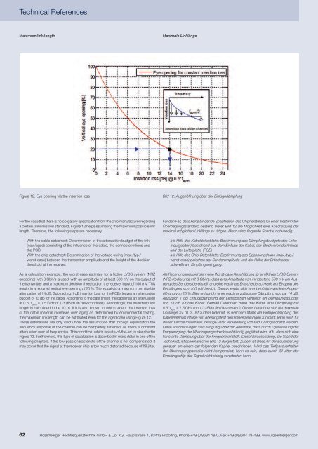
Technical ReferencesMaximum link lengthMaximale LinklängeFigure 12: Eye opening via the insertion lossBild 12: Augenöffnung über der EinfügedämpfungFor the case that there is no obligatory specification from the chip manufacturer regardinga certain transmission standard, Figure 12 helps estimating the maximum possible linklength. Therefore, the following steps are necessary:– With the cable datasheet: Determination of the attenuation budget of the link(new/aged) consisting of the influence of the cable, the connector/inlines andthe PCB– With the chip datasheet: Determination of the voltage swing (max./typ./worst-case) between the transmitter amplitude and the height of the decisionthreshold at the receiver.As a calculation example, the worst-case estimate for a fictive LVDS system (NRZencoding) with 3 Gbit/s is used, with an amplitude of at least 500 mV on the output ofthe transmitter and a maximum decision threshold on the receiver input of 100 mV. Thisresults in a required vertical eye opening of 20 %. This equals to a maximum permissibleattenuation of 14 dB. Subtracting 1 dB insertion loss for the PCBs leaves an attenuationbudget of 13 dB for the cable. According to the data sheet, the cable has an attenuationat 0.5* f sym= 1.5 GHz of 1.3 dB/m (in new condition). Accordingly, the maximum linklength is calculated to be 10 m. If it is also known to which extent the insertion lossof the cable material increases over aging as determined by environmental testing,the maximum link length can be estimated even for the aged case using Figure 12.These estimations are only valid under the assumption that through equalization thefrequency response of the channel can be completely flattened, i.e. there is constantattenuation over all frequencies. This condition, which is state-of-the-art, is sketched inFigure 12. Furthermore, this type of equalization is described in more detail in one of thefollowing chapters. If the low-pass characteristic of the channel is not compensated, itmay occur that the signal at the receiver chip is too much distorted because of ISI jitter.Für den Fall, dass keine bindende Spezifikation des Chipherstellers für einen bestimmtenÜbertragungsstandard besteht, bietet Bild 12 die Möglichkeit eine Abschätzung dermaximal möglichen Linklänge zu tätigen. Hierzu sind folgende Schritte notwendig:– Mit Hilfe des Kabeldatenblatts: Bestimmung des Dämpfungsbudgets des Links(neu/gealtert) bestehend aus dem Einfluss der Kabel, der <strong>Steckverbinder</strong>/Inlinesund der Leiterplatte (PCB)– Mit Hilfe des Chip-Datenblatts: Bestimmung des Spannungshubs (max./typ./worst-case) zwischen der Senderamplitude und der Höhe der Entscheiderschwelleam Empfängereingang.Als Rechnungsbeispiel dient eine Worst-case Abschätzung für ein fiktives LVDS-System(NRZ-Kodierung) mit 3 Gbit/s, dass eine Amplitude von mindestens 500 mV am Ausgangdes Senders bereitstellt und eine maximale Entscheiderschwelle am Eingang desEmpfängers von 100 mV besitzt. Daraus ergibt sich eine benötigte vertikale Augenöffnungvon 20 %. Dies entspricht einer maximal zulässigen Dämpfung von ca. 14 dB.Abzüglich 1 dB Einfügedämpfung der Leiterplatten verbleibt ein Dämpfungsbudgetvon 13 dB für das Kabel. Gemäß Datenblatt habe das Kabel eine Dämpfung bei0.5* f sym= 1,5 GHz von 1,3 dB/m (im Neuzustand). Daraus berechnet sich die maximaleLinklänge zu 10 m. Ist zudem bekannt, in welchem Maße die Einfügedämpfung desKabelmaterials infolge von Alterungstest bei Umweltprüfungen zunimmt, kann auch fürdiesen Fall die maximale Linklänge unter Verwendung von Bild 12 abgeschätzt werden.Diese Abschätzungen sind nur gültig unter der Annahme, dass durch Equalisierung derFrequenzgang der Übertragungsstrecke vollständig geglättet wird, d.h. dass sich einekonstante Dämpfung über der Frequenz einstellt. Diese Voraussetzung, die Stand derTechnik ist, ist schematisch in Bild 12 dargestellt. Zudem ist diese Art der Equalisierunggenauer ein einem der folgenden Kapitel beschrieben. Wird das Tiefpassverhaltender Übertragungsstrecke nicht kompensiert, kann es sein, dass durch ISI Jitter derEmpfangschip das Signal nicht richtig verarbeiten kann.62Rosenberger Hochfrequenztechnik GmbH & Co. KG, Hauptstraße 1, 83413 Fridolfing, Phone +49 (0)8684 18-0, Fax +49 (0)8684 18-499, www.rosenberger.com