<strong>Flüssigkeitsabscheider</strong> <strong>Suction</strong> <strong>Line</strong> <strong>Accumulators</strong> QUALITY PRODUCTS · MADE IN GERMANY Auslegungsdaten Selection Data Flüssigkeits- Kälteleistung Q0 [kW] Effektives abscheider bei 40 °C Verflüssigungstemperatur und 25 °C Sauggastemperatur Förder- Anschlussgröße Verdampfungstemperatur [°C], einstufiger Betrieb volumen <strong>Suction</strong> <strong>Line</strong>- Ref. Capacity Q0 [kW] Effective Accumulator at 40 °C Condensing Temperature and 25°C <strong>Suction</strong>gas temperature Displace- Connection Size Evaporating temperature [°C], single stage operation ment Ø SL Ø SL Typ / Type R 404 A, R 407A, R 407 C, R 507, R 22 R 410 A R134 a Vo mm inch +5 0 –5 –10 –15 –20 –25 –30 –35 –40 +5 –5 –15 –25 +5 –10 –20 –30 m³/h 12 – FA-12/15 Opt. 4,3 3,8 3,2 2,6 2,1 1,7 1,4 1,2 1,0 0,7 6,0 4,4 3,0 2,0 2,8 1,6 1,0 0,6 4,0 Min. 2,2 1,9 1,6 1,3 1,1 0,9 0,7 0,6 0,5 0,4 3,0 2,2 1,5 1,0 1,4 0,8 0,5 0,3 2,0 15 – FA-12/15 Opt. 7,1 6,2 5,4 4,6 3,5 2,9 2,4 1,9 1,6 1,2 10,4 7,4 5,2 3,6 4,7 2,6 1,8 1,1 6,6 Min. 3,6 3,1 2,7 2,3 1,8 1,5 1,2 1,0 0,8 0,6 5,2 3,7 2,6 1,8 2,4 1,3 0,9 0,5 3,3 16 5/8 FA-16… Opt. 8,4 7,6 6,4 5,2 4,1 3,3 2,8 2,3 2,0 1,4 12,0 8,6 6,0 4,0 5,5 3,0 2,0 1,2 7,8 Min. 4,2 3,8 3,2 2,6 2,1 1,7 1,4 1,2 1,0 0,7 6,0 4,3 3,0 2,0 2,8 1,5 1,0 0,6 3,9 18 – FA-18… Opt. 10,9 9,0 7,4 6,0 4,9 4,0 3,2 2,5 2,2 1,6 15,6 10,8 7,4 5,0 7,0 3,8 2,4 1,5 10,2 Min. 5,5 4,5 3,7 3,0 2,5 22,0 1,6 1,3 1,1 0,8 7,8 5,4 3,7 2,5 3,5 1,9 1,2 0,8 5,1 22 7/8 FA-22… Opt. 17,0 15,0 12,6 10,6 8,3 7,0 5,5 4,6 3,8 2,9 25,0 18,0 12,0 8,4 10,2 5,6 3,6 2,4 15,8 Min. 8,5 7,5 6,3 5,3 4,2 3,6 3,0 2,3 1,9 1,5 12,5 9,0 6,0 4,2 5,1 2,8 1,8 1,2 7,9 28 1-1/8 FA-28… Opt. 26,7 23,0 19,0 16,0 13,0 11,0 8,8 7,2 5,8 4,5 38,4 28,0 20,0 13,0 17,5 9,8 6,4 4,0 24,8 Min. 13,4 11,5 9,5 8,0 6,5 5,5 4,5 3,6 2,9 2,3 19,2 14,0 10,0 6,5 8,7 4,9 3,2 2,0 12,4 35 1-3/8 FA-35… Opt. 44 36 32 26 22 18 14,0 12 10 8 64 46 32 22 26,8 15,0 9,8 6,2 40,6 Min. 22 18 16 13 11 9 7,0 6 5 4 32 23 16 11 13,4 7,5 4,9 3,1 20,3 42 1-5/8 FA-42… Opt. 62 52 46 36 30 25 20 16 14 10 94 66 46 32 40 22 14 9,0 57,2 Min. 31 26 23 18 15 13 10 8 7 5 47 33 23 16 20 11 7 4,5 28,6 54 2-1/8 FA-54… Opt. 107 92 76 64 52 43 35 28 24 18 154 110 76 52 70 40 26 16 99,0 Min. 53 46 38 32 26 22 18 14 12 9 77 55 38 26 35 20 13 8 49,5 64 2-1/2 FA-67/64… Opt. 153 128 108 90 75 62 50 42 34 26 220 158 110 76 100 56 36 24 142 Min. 77 64 54 45 38 31 25 21 17 13 110 79 55 38 50 28 18 12 71 67 2-5/8 FA-67… Opt. 168 142 122 100 84 72 58 48 38 30 244 174 122 84 108 62 40 26 148 Min. 84 71 61 50 42 36 29 24 19 15 122 87 61 42 54 31 20 13 74 70 2-3/4 FA-67/70… Opt. 180 154 132 108 90 76 62 50 40 32 268 192 134 92 114 66 44 28 163,0 Min. 90 77 66 54 45 38 31 25 20 16 134 96 67 46 57 33 22 14 81,5 80 3-1/8 FA-80… Opt. 240 208 176 146 124 104 84 70 56 44 356 254 178 122 158 89 58 36 218 Min. 120 104 89 73 62 52 42 35 28 22 178 127 89 61 79 45 29 18 109 89 3-1/2 FA-80/89… Opt. 310 266 226 188 158 132 108 88 72 56 444 318 222 152 202 114 74 48 270 Min. 155 133 113 94 79 66 54 44 36 28 222 159 111 76 101 57 37 24 135 104 4-1/8 FA-104… Opt. 430 360 304 256 210 172 140 116 92 73 600 430 300 200 270 152 98 62 400 Min. 215 180 152 128 105 86 70 58 46 37 300 215 150 100 135 76 49 31 200 Ø SL = Saugleitungs-Außendurchmesser Einsatz nur mit Wärmetauscher oder Heizelementen <strong>Suction</strong> <strong>Line</strong> Outside Diameter Application with heat exchanger or heater elements only Auslegungsbeispiele Examples of Selection Beispiel Verdichter Verdichter Leistungs- Verd.- Auswahlkriterien <strong>ESK</strong>-Produkt Anschluss regelung temp. Example Compressor Compressor Capacity- Evap.- Selection, Information <strong>ESK</strong>-Product Connection Control temp. VH Ø SL Ø SL auf / to to No. m³/h mm inch % °C 1 13 22 7/8 – –20 R407A; Kälteleistung Qo = 4,7 kW; R407A; Capacity Qo = 4,7 kW FA-22W 2 50 35 1-3/8 66 +5 Pc/Po = 2,6; λ = 0,9; Vo = 0,9 x 50 = 45 m³ / h, Vo min = 30 m³ / h FA-42 3 126 54 2-1/8 – –5 90 kg R 22; Kälteleistung Qo = 83 kW 90 kg R 22; Capacity Qo = 83 kW FA-67-32 4 71 35 1-3/8 – – 40 Verdichter zweistufig / Compressor two stage VHL = 71 m³ /h; Vo = VHL x 0,85 = 60 m³ /h FA-54WT oder / or FA-54-7W Verdichter, einstufig VO = λ x VH Compressor, single stage Verdichter, zweistufig VO = 0,85 x VHL Compressor, two stage VHL = Hubvolumen, Niederdruckstufe Displacement, low stage P/P 0 : Druckverhältnis Pressure ratio V0 : Effektives Fördervolumen Effective displacement VH : Theoretisches Hubvolumen Compressor displacement λ : Liefergrad Volumetric efficiency ILC Intelligent Level Control Sight Glasses R717-Recommendations Components for CO2 Accessories Spare Parts 21
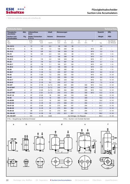
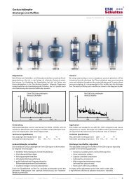
� Visit our website: www.esk-schultze.de Flüssigkeits- Abb. Lötanschluss Inhalt Abmessungen Gewicht DRL abscheider Innen <strong>Suction</strong> <strong>Line</strong>- Fig. Solder Connection Volume Dimensions Weight PED Acculmulator O. D. S. Typ Ø SL Ø SL Ø D H A W Z M Kat./Modul Type mm inch l (dm³) mm mm mm mm mm kg Cat./Module 22 FA-12/15 a 12 1/2 0,3 58 140 95 – – – 0,6 – FA-16-1,5 b 16 5/8 1,5 108 250 60 – – M10 2,0 – FA-16-2 b 16 5/8 2,0 108 320 60 – – M10 2,5 I / A FA-16 c 16 5/8 2,3 125 254 60 – – M10 2,0 I / A FA-18-2 b 18 – 2,0 108 289 60 – – M10 2,5 I / A FA-22-2 b 22 7/8 2,0 108 329 60 – – M10 2,7 I / A FA-22 c 22 7/8 3,5 125 387 60 – – M10 2,7 I / A FA-22-7 c 22 7/8 7,1 195 321 100 – – M10 6,0 I / A FA-28-2 b 28 1-1/8 2,0 108 336 60 – – M10 2,9 I / A FA-28 c 28 1-1/8 3,5 125 392 60 – – M10 2,9 I / A FA-28-7 c 28 1-1/8 7,5 200 327 100 – – M10 6,0 II / A1 FA-35 c 35 1-3/8 7,5 200 332 100 – – M10 6,0 II / A1 FA-42 c 42 1-5/8 7,5 200 335 100 – – M10 6,0 II / A1 FA-54-7 c 54 2-1/8 7,5 200 340 100 – – M10 6,5 II / A1 FA-54-9 c 54 2-1/8 9,5 200 417 100 – – M10 7,5 II / A1 FA-54T d 54 2-1/8 2 x 7,5 200 359 300 – 300 M12 12,5 II / A1 FA-67/64T d 64 2-1/2 2 x 7,5 200 401 300 – 300 M12 14,0 II / A1 FA-67T d 67 2-5/8 2 x 7,5 200 364 300 – 300 M12 13,0 II / A1 FA-67/70T d 70 2-3/4 2 x 7,5 200 410 300 – 300 M12 14,0 II / A1 FA-67-18 e 67 2-5/8 18 300 468 150 300 – 18,0 II / A1 FA-80 e 80 3-1/8 18 300 471 150 – 300 – 18,0 II / A1 FA-80/89 e 89 3-1/2 18 300 530 150 – 300 – 19,0 II / A1 FA-54-32 f 54 2-1/8 32 273 838 231 – 294 – 41,1 II / A1 FA-67-32 f 67 2-5/8 32 273 804 197 – 294 – 36,3 II / A1 FA-80-32 f 80 3-1/8 32 273 854 262 – 294 – 41,7 II / A1 FA-89-32 f 89 3-1/2 32 273 854 262 – 294 – 41,7 II / A1 FA-104-32 f 104 4-1/8 32 273 812 221 – 294 – 39,2 II / A1 FA-104-64T – 104 4-1/8 2x32 Auf Anfrage / On Request 84,4 II / A1 Ø SL = Saugleitungs-Außendurchmesser Ø SL = <strong>Suction</strong> <strong>Line</strong> Outside Diameter <strong>Flüssigkeitsabscheider</strong> <strong>Suction</strong> <strong>Line</strong> <strong>Accumulators</strong> Technische Daten Technical Data a b c d e f Discharge <strong>Line</strong> Mufflers Oil Separators � <strong>Suction</strong> <strong>Line</strong> <strong>Accumulators</strong> Oil Control System Filter Driers Liquid Receivers