ANLEITUNG Heinkel He 111 - DMT
ANLEITUNG Heinkel He 111 - DMT
ANLEITUNG Heinkel He 111 - DMT

Erfolgreiche ePaper selbst erstellen
Machen Sie aus Ihren PDF Publikationen ein blätterbares Flipbook mit unserer einzigartigen Google optimierten e-Paper Software.
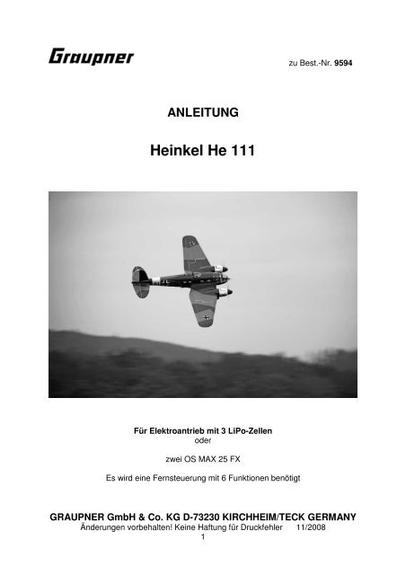
<strong>ANLEITUNG</strong><br />
<strong><strong>He</strong>inkel</strong> <strong>He</strong> <strong>111</strong><br />
Für Elektroantrieb mit 3 LiPo-Zellen<br />
oder<br />
zwei OS MAX 25 FX<br />
Es wird eine Fernsteuerung mit 6 Funktionen benötigt<br />
zu Best.-Nr. 9594<br />
GRAUPNER GmbH & Co. KG D-73230 KIRCHHEIM/TECK GERMANY<br />
Änderungen vorbehalten! Keine Haftung für Druckfehler 11/2008<br />
1
Technische Daten<br />
Spannweite ca. 1750 mm<br />
Länge ü.a. ca. 1280 mm<br />
Tragflügelprofil sym. 17 %<br />
Höhenleitwerksprofil sym. 7 %<br />
Flächeninhalt ca. 48 dm²<br />
Höhenleitwerksinhalt ca. 6,6 dm²<br />
Fluggewicht je nach<br />
Ausrüstung ab ca. 3000 g<br />
EWD ca. 0,5°-1°<br />
Schwerpunkt ca. ca. 140 mm hinter der Nasenleiste<br />
Vorwort<br />
Es wurde besonders Wert auf ein geringes Abfluggewicht gelegt, was sich in den<br />
Flugleistungen und Flugeigenschaften wiederspiegelt. Die Flugeigenschaften der<br />
<strong><strong>He</strong>inkel</strong> <strong>He</strong> <strong>111</strong> sind sehr ausgewogen. Einfacher Kunstflug ist möglich. Der Aufbau<br />
des Modells ist überwiegend aus Balsaholz gefertigt. An besonders beanspruchten<br />
Stellen sind Verstärkungen aus Sperrholz eingeleimt.<br />
Rumpf, Tragflügel, Seiten- und Höhenleitwerk sind zweifarbig mit Bügelfolie<br />
bespannt. Für die Fertigstellung sind nur wenige Arbeitsgänge notwendig, wie z.B.<br />
das Ankleben der Seitenleitwerke, den Einbau von Motorträgern mit Motoren, des<br />
Fahrwerks sowie die Fernlenkanlage mit ihren Anlenkungen.<br />
Zum Fliegen des Modells reicht eine RC-Anlage mit 6 Funktionen.<br />
Achtung: Dieses Modell ist kein Spielzeug!<br />
Sollten Sie mit solch motorisiertem Modell keine Erfahrung haben, wenden Sie sich<br />
bitte an erfahrene Modellflieger, die Sie unterstützen können. Es könnte zu<br />
Verletzungen kommen, wenn das Modell ohne Vorkenntnisse in Betrieb genommen<br />
wird. Denken Sie an die Sicherheit und Ihre Gesundheit.<br />
Wichtige Sicherheitshinweise<br />
Sie haben einen Bausatz erworben, aus dem – zusammen mit entsprechendem<br />
geeignetem Zubehör – ein funktionsfähiges RC-Modell fertiggestellt werden kann.<br />
Die Einhaltung der Montage- und Betriebsanleitung im Zusammenhang mit dem<br />
Modell sowie die Installation, der Betrieb, die Verwendung und Wartung der mit dem<br />
Modell zusammenhängenden Komponenten können von GRAUPNER nicht<br />
überwacht werden. Daher übernimmt GRAUPNER keinerlei Haftung für Verluste,<br />
Schäden oder Kosten, die sich aus dem fehlerhaften Betrieb, aus fehlerhaftem<br />
Verhalten bzw. in irgendeiner Weise mit dem vorgenannten zusammenhängend<br />
ergeben. Soweit vom Gesetzgeber nicht zwingend vorgeschrieben, ist die<br />
Verpflichtung der Firma GRAUPNER zur Leistung von Schadensersatz, aus welchem<br />
Grund auch immer ausgeschlossen (inkl. Personenschäden, Tod, Beschädigung von<br />
Gebäuden sowie auch Schäden durch Umsatz- oder Geschäftsverlust, durch<br />
Geschäftsunterbrechung oder andere indirekte oder direkte Folgeschäden), die von<br />
dem Einsatz des Modells herrühren.<br />
GRAUPNER GmbH & Co. KG D-73230 KIRCHHEIM/TECK GERMANY<br />
Änderungen vorbehalten! Keine Haftung für Druckfehler 11/2008<br />
2
Die Gesamthaftung ist unter allen Umständen und in jedem Fall beschränkt auf den<br />
Betrag, den Sie tatsächlich für dieses Modell gezahlt haben.<br />
Die Inbetriebnahme und der Betrieb des Modells erfolgt einzig und allein auf<br />
Gefahr des Betreibers. Nur ein vorsichtiger und überlegter Umgang beim<br />
Betrieb schützt vor Personen- und Sachschäden.<br />
Nach der neuen Regelung des §103 Abs. 3 LuftVZO müssen alle Flugmodelle, egal<br />
ob Slowflyer, Parkflyer, Segelflugzeuge, Flugmodelle mit Antrieben jeglicher Art vor<br />
Aufnahme des Flugbetriebs versichert sein. Schließen Sie daher eine spezielle RC-<br />
Modell-Haftplichtversicherung ab. Fragen hierzu, werden Ihnen vom Fachhandel<br />
gerne beantwortet.<br />
Diese Sicherheitshinweise müssen unbedingt aufbewahrt werden und müssen bei<br />
einem Weiterverkauf des Modells an den Käufer weitergegeben werden.<br />
Garantiebedingungen<br />
Die Garantie besteht aus der kostenlosen Reparatur bzw. dem Umtausch von<br />
solchen Teilen, die während der Garantiezeit von 24 Monaten, ab dem Datum des<br />
Kaufes nachgewiesene Fabrikations- oder Materialfehler aufweisen. Weitergehende<br />
Ansprüche sind ausgeschlossen. Transport-, Verpackungs- und Fahrtkosten gehen<br />
zu Lasten des Käufers. Für Transportschäden wird keine Haftung übernommen. Bei<br />
der Einsendung an GRAUPNER bzw. an die für das jeweilige Land zuständige<br />
Servicestelle sind eine sachdienliche Fehlerbeschreibung und die Rechnung mit dem<br />
Kaufdatum beizufügen. Die Garantie ist hinfällig, wenn der Ausfall des Teils oder des<br />
Modells von einem Unfall, unsachgemäßer Behandlung oder falscher Verwendung<br />
herrührt.<br />
Wichtig! Bevor Sie mit dem Bau beginnen!<br />
Auch wenn Sie schon viele RC-Modelle gebaut haben, lesen Sie diese Anleitung<br />
genauestens durch und kontrollieren Sie die Teile dieses Bausatzes auf<br />
Vollständigkeit. Es wurde viel Mühe darauf verwandt, den Aufwand möglichst<br />
einfach zu halten, ohne die Sicherheit zu beeinträchtigen.<br />
Das weitgehend vorgefertigte Modell benötigt nur noch wenig Bauzeit. Aber die<br />
verbleibenden Arbeiten sind wichtig und müssen sorgfältig ausgeführt werden. Von<br />
deren einwandfreier Ausführung hängt es ab, ob das Modell letztlich die<br />
vorgesehene Festigkeit und Flugeigenschaften haben wird; deshalb langsam und<br />
präzise arbeiten!<br />
Hinweise zur Folienbespannung<br />
Auf Grund von starken Wetterveränderungen (Temperatur, Feuchtigkeit etc.) können<br />
in der Bespannfolie kleine Falten auftreten. In seltenen Fällen auch ein Verzug der<br />
Bauteile. Dies liegt in der Natur der Holzbauweise mit Folienbespannung. Es kann,<br />
wie folgt, mit einem <strong>He</strong>ißluftgebläse (Fön), wie sie für den Modellbauer angeboten<br />
werden, wieder korrigiert werden.<br />
Falten: Mit Warmluft anblasen und mit weichem Tuch anreiben.<br />
Verzogener Flügel: Flügel dem Verzug entgegen leicht verdreht aufspannen und mit<br />
Bügeleisen oder Warmluft die Bespannung wieder glätten.<br />
GRAUPNER GmbH & Co. KG D-73230 KIRCHHEIM/TECK GERMANY<br />
Änderungen vorbehalten! Keine Haftung für Druckfehler 11/2008<br />
3
Vorsicht! Nicht mehr Wärme zuführen, als unbedingt notwendig. Bei zu heißem<br />
Bügeleisen schmilzt die Folie und es entstehen Löcher.<br />
Wenn Blechschrauben in Holz eingeschraubt werden, diese durch Weißleim<br />
gegen Lösen sichern: Weißleim in Bohrung einspritzen und Schraube<br />
eindrehen.<br />
Hinweis zur Benutzung von <strong><strong>He</strong>inkel</strong> <strong>He</strong> <strong>111</strong><br />
Vor dem Versuch der ersten Inbetriebnahme muss die gesamte Betriebs- und<br />
Montageanleitung sorgfältig gelesen werden. Sie alleine sind verantwortlich<br />
für den sicheren Betrieb Ihres RC-Flugmodells. Bei Jugendlichen unter 14<br />
Jahren muss der Bau und Betrieb von einem Erwachsenen, der mit den<br />
Gegebenheiten und möglichen Gefahren eines RC-Flugmodells vertraut ist,<br />
verantwortlich überwacht werden.<br />
Diese Bedienungsanleitung muss sorgfältig aufbewahrt und im Falle einer<br />
Weitergabe dem nachfolgenden Benutzer unbedingt mit ausgehändigt werden.<br />
Fragen, die die Sicherheit beim Betrieb des RC-Flugmodells betreffen, werden<br />
Ihnen vom Fachhandel gerne beantwortet.<br />
Fernsteuer-Flugmodelle sind sehr anspruchsvolle und gefährliche<br />
Gegenstände und erfordern vom Betreiber einen hohen Sachverstand, Können<br />
und Verantwortungsbewusstsein.<br />
Rechtlich gesehen, ist ein Flugmodell ein Luftfahrzeug und unterliegt<br />
entsprechenden Gesetzen, die unbedingt eingehalten werden müssen. Die<br />
Broschüre »Modellflugrecht, Paragrafen und mehr«, Best.-Nr. 8034.02, stellt<br />
eine Zusammenfassung dieser Gesetze dar; sie kann auch beim Fachhandel<br />
eingesehen werden. Ferner müssen postalische Auflagen, die die<br />
Fernlenkanlage betreffen, beachtet werden. Entsprechende Hinweise finden<br />
Sie in der Bedienungsanleitung Ihrer Fernsteueranlage.<br />
Es dürfen nur die im Bausatz enthaltenen Teile, sowie die ausdrücklich von<br />
uns empfohlenen Original-Graupner-Zubehör- und Ersatzteile verwendet<br />
werden. Wird auch nur eine Komponente der Antriebseinheit geändert, ist ein<br />
sicherer Betrieb nicht mehr gewährleistet und es erlischt jeglicher etwaiger<br />
Garantieanspruch.<br />
Verwenden Sie immer nur passende, verpolungssichere Steckverbindungen.<br />
Alle stromführenden Leitungen, Steckverbindungen, sowie die<br />
Antriebsbatterie, bei Selbstkonfektionierung, kurzschlusssicher isolieren.<br />
Kombinieren Sie niemals unterschiedliche, z. B. Blech- und Goldkontakte, da<br />
hier keine sichere Funktion gewährleistet ist.<br />
Bei Verwendung von Schaltern bzw. Reglern mit Empfängerstromversorgung<br />
nur Steckverbindungen mit Graupner-Gold-Kontakten verwenden.<br />
Kurzschlüsse und Falschpolungen vermeiden.<br />
Durch die hohe Energie der LiPo-Batterien besteht Explosions- und<br />
Brandgefahr.<br />
Ein RC- Flugmodell kann nur funktionsfähig sein und den Erwartungen<br />
entsprechen, wenn es im Sinne der Bauanleitung sorgfältigst gebaut wurde.<br />
GRAUPNER GmbH & Co. KG D-73230 KIRCHHEIM/TECK GERMANY<br />
Änderungen vorbehalten! Keine Haftung für Druckfehler 11/2008<br />
4
Nur ein vorsichtiger und überlegter Umgang beim Betrieb schützt vor<br />
Personen- und Sachschäden. Niemand würde sich in ein Flugzeug setzen und<br />
ohne vorausgegangene Schulung - versuchen, damit zu fliegen. Auch<br />
Modellfliegen will gelernt sein.<br />
Der <strong>He</strong>rsteller hat jedoch keine Möglichkeit, den Bau und den Betrieb eines<br />
RC- Flugmodells zu beeinflussen. Deshalb wird hiermit auf die Gefahren<br />
nachdrücklich hingewiesen und jede Haftung dafür abgelehnt.<br />
Bitte wenden Sie sich dazu an erfahrene Modellflieger, an Vereine oder<br />
Modellflugschulen. Ferner sei auf den Fachhandel und die einschlägige<br />
Fachpresse verwiesen. Am besten als Club-Mitglied auf zugelassenem<br />
Modellflugplatz fliegen.<br />
Sie alleine sind verantwortlich für den sicheren Betrieb Ihres RC- Flugmodells.<br />
Fragen, die die Sicherheit beim Betrieb des RC- Flugmodells betreffen, werden<br />
Ihnen vom Fachhandel gerne beantwortet.<br />
Klebstoffe und Lacke enthalten Lösungsmittel, die unter Umständen<br />
gesundheitsschädlich sein können. Beachten Sie daher unbedingt auch die<br />
entsprechenden Hinweise und Warnungen der <strong>He</strong>rsteller.<br />
Der Betreiber muss im Besitz seiner vollen körperlichen und geistigen<br />
Fähigkeiten sein. Wie beim Autofahren, ist der Betrieb des Flugmodells unter<br />
Alkohol oder Drogeneinwirkung nicht erlaubt.<br />
Informieren Sie alle Passanten und Zuschauer vor der Inbetriebnahme über alle<br />
möglichen Gefahren, die von Ihrem Modell ausgehen und ermahnen diese, sich<br />
in ausreichendem Schutzabstand, wenigstens 5 m hinter der<br />
Luftschraubenebene, aufzuhalten.<br />
Stets mit dem notwendigen Sicherheitsabstand zu Personen oder<br />
Gegenständen fliegen; nie Personen in niedriger Höhe überfliegen oder auf sie<br />
zufliegen!<br />
Modellflug darf nur bei Außentemperaturen von - 5º C bis + 35º C betrieben<br />
werden. Extremere Temperaturen können zu Veränderungen von z. B.<br />
Akkukapazität, Werkstoffeigenschaften und mangelhafte Klebeverbindungen<br />
führen.<br />
Jeder Modellflieger hat sich so zu verhalten, dass die öffentliche Sicherheit<br />
und Ordnung, insbesondere andere Personen und Sachen, sowie die Ordnung<br />
des Modellflugbetriebs nicht gefährdet oder gestört wird.<br />
Das Flugmodell niemals in der Nähe von Hochspannungsleitungen,<br />
Industriegelände, in Wohngebieten, öffentlichen Straßen, Plätzen, Schulhöfen,<br />
Parks und Spielplätzen usw. fliegen lassen.<br />
Warnungen müssen unbedingt beachtet werden. Sie beziehen sich auf Dinge<br />
und Vorgänge, die bei einer Nichtbeachtung zu schweren - in Extremfällen<br />
tödlichen Verletzungen oder bleibenden Schäden führen können.<br />
GRAUPNER GmbH & Co. KG D-73230 KIRCHHEIM/TECK GERMANY<br />
Änderungen vorbehalten! Keine Haftung für Druckfehler 11/2008<br />
5
Luftschrauben und generell alle sich drehenden Teile, die durch einen Motor<br />
angetrieben werden, stellen eine ständige Verletzungsgefahr dar. Sie dürfen<br />
mit keinem Körperteil berührt werden! Eine schnell drehende Luftschraube<br />
kann z. B. einen Finger abschlagen!<br />
Sich niemals in oder vor der Drehebene von Luftschrauben aufhalten! Es<br />
könnte sich doch einmal ein Teil davon lösen und mit hoher Geschwindigkeit<br />
und viel Energie wegfliegen und Sie oder Dritte treffen. Darauf achten, dass<br />
kein sonstiger Gegenstand mit einer laufenden Luftschraube in Berührung<br />
kommt!<br />
Die Blockierung der Luftschraube, durch irgendwelche Teile, muss<br />
ausgeschlossen sein.<br />
Vorsicht bei losen Kleidungsstücken wie Schals, weiten <strong>He</strong>mden usw.: sie<br />
werden vom Propellerstrahl angesaugt und können in den Luftschraubenkreis<br />
gelangen.<br />
Überprüfen Sie vor jeder Inbetriebnahme das Modell und alle an ihm<br />
gekoppelten Teile (z. B. Luftschrauben, Getriebe, RC- Teile usw.) auf festen Sitz<br />
und mögliche Beschädigungen. Das Modell darf erst nach Beseitigung aller<br />
Mängel in Betrieb genommen werden.<br />
Auf gute Standfestigkeit achten, wenn Sie das Modell in der Hand halten.<br />
Passendes Schuhwerk, z. B. Sportschuhe tragen.<br />
Vergewissern Sie sich, dass die verwendete Frequenz frei ist. Erst dann<br />
einschalten! Funkstörungen, verursacht durch Unbekannte, können stets ohne<br />
Vorwarnung auftreten! Das Modell ist dann steuerlos und unberechenbar!<br />
Fernlenkanlage nicht unbeaufsichtigt lassen, um ein Betätigen durch Dritte zu<br />
verhindern.<br />
Elektromotor nur einschalten, wenn nichts im Drehbereich der Luftschraube<br />
ist. Nicht versuchen, die laufende Luftschraube anzuhalten. Elektromotor mit<br />
Luftschraube nur im fest eingebauten Zustand laufen lassen.<br />
Die Fluglage des Modells muss während des gesamten Fluges immer eindeutig<br />
erkennbar sein, um immer ein sicheres Steuern und Ausweichen zu<br />
gewährleisten. Machen sich während des Fluges<br />
Funktionsbeeinträchtigungen/Störungen bemerkbar, muss aus<br />
Sicherheitsgründen sofort die Landung eingeleitet werden. Sie haben anderen<br />
Luftfahrzeugen stets auszuweichen. Start- und Landeflächen müssen frei von<br />
Personen und sonstigen Hindernissen sein.<br />
Immer auf vollgeladene Akkus achten, da sonst keine einwandfreie Funktion<br />
der RC-Anlage gewährleistet ist.<br />
Niemals heiß gewordene, defekte oder beschädigte Batterien verwenden. Es<br />
sind stets die Gebrauchsvorschriften des Batterieherstellers zu beachten.<br />
GRAUPNER GmbH & Co. KG D-73230 KIRCHHEIM/TECK GERMANY<br />
Änderungen vorbehalten! Keine Haftung für Druckfehler 11/2008<br />
6
Vor jedem Flug eine Überprüfung der kompletten RC-Anlage, sowie des<br />
Flugmodells auf volle Funktionstüchtigkeit und Reichweite durchführen.<br />
Dabei ist zu beachten, dass bei der Inbetriebnahme die Motorsteuerfunktion am<br />
Sender immer zuerst in AUS-Stellung gebracht wird. Danach Sender und dann<br />
erst Empfangsanlage einschalten, um ein unkontrolliertes Anlaufen des<br />
Elektromotors zu vermeiden. Gleichfalls gilt immer zuerst Empfangsanlage<br />
ausschalten, danach erst den Sender.<br />
Überprüfen Sie, dass die Ruder sich entsprechend der Steuerknüppelbetätigung<br />
bewegen.<br />
Beim Bewegen des Querruder-Steuerknüppels nach rechts, muss das rechte<br />
Querruder nach Oben und das linke Querruder nach unten ausschlagen.<br />
Beim Bewegen des Höhen-/Tiefenruder-Knüppels nach hinten, zum Bauch,<br />
muß das Ruder nach oben ausschlagen.<br />
Beim Fliegen keine abrupten Steuerknüppelbewegungen durchführen.<br />
Mit diesen Hinweisen soll auf die vielfältigen Gefahren hingewiesen werden,<br />
die durch unsachgemäße und verantwortungslose Handhabung entstehen<br />
können. Richtig und gewissenhaft betrieben ist Modellflug eine kreative,<br />
lehrreiche und erholsame Freizeitgestaltung.<br />
Hinweise zum Bau und Flugbetrieb von <strong><strong>He</strong>inkel</strong> <strong>He</strong> <strong>111</strong><br />
Bevor mit dem Bau begonnen wird:<br />
Achten Sie beim Kauf einer Funkfernsteuerung darauf, dass die Sende- und<br />
Empfangsgeräte auch für Flugmodelle geeignet und bei der Deutschen<br />
Bundespost-Telekom zugelassen sind, sowie eine FTZ-Serienprüfnummer besitzen.<br />
In den Frequenzbereichen für Funkfernsteuerung werden auch andere Funkanlagen<br />
und Hochfrequenzgeräte betrieben. Deshalb kann kein Schutz vor Störungen durch<br />
solche Geräte gewährt werden.<br />
Weitere Informationen zu diesem Thema bekommen Sie bei Ihrer örtlichen Telekom-<br />
Niederlassung oder bei Ihrem Modellbau-Fachhändler.<br />
Anleitung und Warnhinweise zur Benutzung von LiPo – Akkus<br />
Den allgemeinen Hinweis für die Benutzung von LiPo- Akkus entnehmen<br />
Sie bitte die dem Akkupack beiliegenden Beipackzettel.<br />
Allgemeine Warnhinweise<br />
Die Akkus dürfen nicht in Feuer gelangen oder eingeäschert werden.<br />
Ebenso dürfen die Zellen nicht in Flüssigkeiten wie Wasser, Meerwasser oder<br />
Getränke eingetaucht werden. Jeder Kontakt mit Flüssigkeit gleich welcher Art ist zu<br />
vermeiden.<br />
Einzelne Zellen und Akkus sind kein Spielzeug und dürfen deshalb nicht in die<br />
Hände von Kindern gelangen. Akkus/Zellen außerhalb der Reichweite von Kindern<br />
aufbewahren.<br />
GRAUPNER GmbH & Co. KG D-73230 KIRCHHEIM/TECK GERMANY<br />
Änderungen vorbehalten! Keine Haftung für Druckfehler 11/2008<br />
7
Akkus dürfen nicht in die Nähe von Babys oder Kleinkinder gelangen. Sollten Akkus<br />
verschluckt worden sein, so ist sofort ein Arzt oder Notarzt aufzusuchen.<br />
Akkus dürfen nicht in eine Mikrowelle oder unter Druck geraten. Rauch und Feuer<br />
und noch mehr können die Folgen sein.<br />
Zerlegen Sie niemals einen LiPo-Akku. Das Zerlegen eines Akkus kann interne<br />
Kurzschlüsse verursachen. Gasentwicklung, Feuer und Explosionen oder andere<br />
Probleme können die Folge sein.<br />
Die in den LiPo-Akkus enthaltenen Elektrolyte und Elektrolytdämpfe sind<br />
gesundheitsschädlich. Vermeiden Sie in jedem Fall direkten Kontakt mit Elektrolyte.<br />
Bei Kontakt von Elektrolyte mit Haut, Augen oder anderen Körperteilen muss ein<br />
sofortiges Aus- oder Abspülen mit ausreichend frischem Wasser vorgenommen<br />
werden, anschließend muss ein Arzt konsultiert werden.<br />
Im Gerät eingebaute Akkus immer aus den Geräten entnehmen, wenn das Gerät<br />
gerade nicht verwendet wird. Geräte nach dem Gebrauch immer ausschalten um<br />
Tiefentladungen zu vermeiden. Akkus immer rechtzeitig aufladen. Akkus auf einer<br />
nicht brennbaren, hitzebeständigen und nicht leitenden Unterlage lagern!<br />
Tiefentladene Li-Po Akkus sind defekt und dürfen nicht mehr verwendet werden!<br />
• WICHTIG: Der im Modell eingebaute Akku darf nicht im Hausmüll entsorgt<br />
werden. Der Akku muss in Altbatterierücknahmebehältern entsorgt werden.<br />
• WICHTIG: Das Modell und der Sender dürfen nicht im Hausmüll entsorgt werden<br />
und müssen auf einem Wertstoffhof als Elektroschrott abgegeben werden.<br />
Erkundigen Sie sich hierzu bei Ihrer Gemeinde.<br />
Während der Bauphase<br />
RC-Teile, sowie Rudergestänge werden während des Zusammenbaus nach den<br />
entsprechenden Baustufen eingebaut. Ein späterer Einbau ist gar nicht oder nur<br />
sehr schwierig möglich.<br />
Wenn Blechschrauben in Holz eingeschraubt werden, diese durch Weißleim<br />
gegen Lösen sichern: Weißleim in Bohrung einspritzen und Schraube<br />
eindrehen.<br />
Die Bauanleitung<br />
ist größtenteils in Reihenfolge gehalten. Die nachfolgenden Hinweise sollen noch<br />
zusätzlich einige Erläuterungen geben.<br />
Abweichungen von der aufgeführten Reihenfolge beim Bau des Modells sind nach<br />
eigenem Ermessen vorzunehmen.<br />
Achten Sie darauf, dass Balsamesser, Stecknadeln, dünne Drahtenden usw. spitz<br />
bzw. scharf sind und somit leicht zu Verletzungen führen können.<br />
Achten Sie darauf, dass Kinder keinen Zugang zu Werkzeugen, Klebstoffen oder<br />
Lacken haben.<br />
Sorgen Sie bei Klebstoffen mit Lösungsmitteln für einen gut belüfteten Raum.<br />
Geben Sie Klebstoff- und Farbreste bei Sondermüllsammelstellen ab.<br />
Eine großzügig bemessene freie Arbeitsfläche ist bei allen Bastelarbeiten von<br />
besonderem Vorteil.<br />
GRAUPNER GmbH & Co. KG D-73230 KIRCHHEIM/TECK GERMANY<br />
Änderungen vorbehalten! Keine Haftung für Druckfehler 11/2008<br />
8
Lassen Sie sich schwierige Arbeitsgänge von erfahrenen Modellbauern zeigen,<br />
wenn Sie noch wenig Erfahrung im Modellbau haben.<br />
Verhaltensregeln<br />
Betreiben Sie Ihr Modell niemals auf öffentlichen Straßen, Wegen und Plätzen,<br />
Gebäuden oder in der Nähe von Hochspannungsleitungen.<br />
Lassen Sie die <strong><strong>He</strong>inkel</strong> <strong>He</strong> <strong>111</strong> niemals in Naturschutz- oder<br />
Landschaftsschutzgebieten fliegen. Nehmen Sie Rücksicht auf die dort lebenden<br />
Tiere und Pflanzen.<br />
Bäume und Sträucher dienen als Kinderstube, Nist- und Lebensraum von Vögeln.<br />
Gefährden Sie niemals Tiere, Zuschauer oder andere Piloten.<br />
Funkfernsteuerung für <strong><strong>He</strong>inkel</strong> <strong>He</strong> <strong>111</strong><br />
Als Funkfernsteuerung schlagen wir folgende minimale Ausrüstung vor:<br />
1 Computer System mx 12 im 35 MHz-Band, z. B. Best.-Nr. 4722<br />
6 Servo DS 368 Best.-Nr. 5162<br />
1 Servo 713 Best.-Nr. 3887<br />
2 Verlängerungskabel Best.-Nr. 3935.18<br />
7 Verlängerungskabel Best.-Nr. 3935.32<br />
1 V-Kabel Best.-Nr. 3936.11<br />
1 Hochflexible Kupferlitze Best.-Nr. 3389<br />
2 Gold-Buchsen G3,5 Best.-Nr. 2969<br />
2 Gold-Stecker G3,5 Best.-Nr. 2970<br />
1 G3,5 verpolungssicheres Kunststoffteil Best.-Nr. 2969.K<br />
entsprechenden Ladegeräte dazu siehe GRAUPNER Hauptkatalog FS.<br />
Elektroantrieb und Zubehör<br />
2 COMPACT 400 Z 11,1V Best.-Nr. 7745<br />
2 BRUSHLESS CONTROL 45 Best.-Nr. 7235<br />
1 Verteilerkabel Best.-Nr. 2969.V<br />
1 LiPo-Akku-Pack Best.-Nr. 7664.3<br />
1 ELEKTRO PROP Luftschraube Best.-Nr. 1328.28.12,5<br />
1 ELEKTRO PROP Luftschraube Best.-Nr. 1328.28.12,5 L<br />
1 Klett-Kabelbinder Best.-Nr. 1587<br />
Verbrennerantrieb und Zubehör<br />
Motor<br />
Hubraum Schalldämpfer<br />
Best.-Nr. cm³ Best.-Nr.<br />
OS MAX 25 FX<br />
1870<br />
Luftschraube<br />
Best.-Nr.<br />
4,07 1828.33 1316.23.15 1682<br />
alle Teile, in der Tabelle, werden zweimal benötigt<br />
Glühkerze<br />
Best.-Nr.<br />
Das Modell ist sehr weit und hervorragend vorgefertigt, Motorhaube und<br />
Motorgondeln in GFK liegt dem Bausatz bei. Falls erforderlich, fönen Sie zuerst<br />
sämtliche bespannten Holzteile nach, insbesondere an Kanten und im Bereich von<br />
Scharnieren bzw. Folienstößen. Es ist empfehlenswert, Anschlagseiten, an denen die<br />
Ruderscharniere eingeklebt werden, komplett mit Tesafilm kristallklar zu überkleben,<br />
GRAUPNER GmbH & Co. KG D-73230 KIRCHHEIM/TECK GERMANY<br />
Änderungen vorbehalten! Keine Haftung für Druckfehler 11/2008<br />
9
weil unter Umständen Feuchtigkeit die Folie an solchen Stellen abheben bzw.<br />
anlösen können.<br />
Erforderliches Material und Werkzeug<br />
Spiralbohrer Ø 1,5 mm z.B. Best.-Nr. 574.1,5<br />
Spiralbohrer Ø 2,0 mm z.B. Best.-Nr.574.2<br />
Schraubendreher Kreuzschlitz und Langschlitz<br />
Sechskant- Schraubendreher z.B. Best.– Nr.5735.1,5 und 2,0<br />
Flachzange<br />
Seitenschneider<br />
Klebstoffe<br />
Holzleim, z. B. UHU coll, Best.-Nr. 958.60<br />
UHU hart, z. B. Best.-Nr. 534.10<br />
Sekundenkleber dünnflüssig, z. B. Best.-Nr. 5822<br />
Der Zusammenbau der <strong><strong>He</strong>inkel</strong> <strong>He</strong> <strong>111</strong><br />
Beginnen Sie erst mit dem Zusammenbau, wenn Sie sich mit den Bauteilen und<br />
einzelnen Baustadien vertraut gemacht haben. Sollte ein Bauteil Grund zur<br />
Beanstandung geben, so ist die vor Baubeginn Ihrem Fachhändler mitzuteilen.<br />
Es besteht die Möglichkeit die <strong><strong>He</strong>inkel</strong> <strong>He</strong> <strong>111</strong> als Elektro- oder als Verbrennermodell<br />
zusammenzubauen, dies muss vor Baubeginn entschieden werden.<br />
Der Tragflügel<br />
Zum Einkleben der Scharniere in Querruder und Landeklappen auf diesen die Mitte<br />
mit einem Bleistift anzeichnen.<br />
Jetzt wercen die Scharniere bis zum Bleistiftstrich in die Ruder geklebt. Als Klebstoff<br />
kann dünnflüssiger Sekundenkleber verwendet werden. Die Scharniere ca. 1 mm tief<br />
in den Aufnahmeschlitz stecken, Sekundenkleber rechts und links jeweils auftragen<br />
und die Scharniere bis zum Bleistiftstrich einschieben.<br />
Nach dem Trocknen des Klebstoffes die Querruder und Landeklappen mittels der<br />
Scharniere probeweise, zur Kontrolle der Passgenauigkeit, an die Tragflächen<br />
stecken.<br />
GRAUPNER GmbH & Co. KG D-73230 KIRCHHEIM/TECK GERMANY<br />
Änderungen vorbehalten! Keine Haftung für Druckfehler 11/2008<br />
10
Jetzt die Ruder wieder ein Stück herausziehen, Klebstoff auf die Scharniere<br />
auftragen und bis zu einem Spalt von ca. 0,5 mm in die Bauteile schieben.<br />
Die Aussparung für die Querruderservo mit den Fingern ertasten und mit einem<br />
heißen Lötkolben freischmelzen oder einem scharfen Messer freischneiden.<br />
Servoanschlusskabel mit dem entsprechenden Verlängerungskabel verlängern,<br />
Steckverbindung gegen Lösen sichern.<br />
GRAUPNER GmbH & Co. KG D-73230 KIRCHHEIM/TECK GERMANY<br />
Änderungen vorbehalten! Keine Haftung für Druckfehler 11/2008<br />
11
Servokabel in die Tragfläche einziehen.<br />
Die Servos mit den den Servo beiliegenden Schrauben, Gummitüllen und Hohlnieten<br />
in den Tragflächen befestigen.<br />
Wie auf dem Foto zu sehen den Servohebel bearbeiten und das äußerste Loch auf<br />
Ø 2 mm aufbohren.<br />
Gestängeanschluss so in den Servohebel montieren, dass er sich ohne merkliches<br />
Spiel drehen lässt.<br />
Die Mutter mit UHU schraubensicher gegen lösen sichern.<br />
GRAUPNER GmbH & Co. KG D-73230 KIRCHHEIM/TECK GERMANY<br />
Änderungen vorbehalten! Keine Haftung für Druckfehler 11/2008<br />
12
Bei Servo in Neutralstellung den Servohebel auf das Servo montieren.<br />
Mit den Fingern die Aussparung für das Ruderhorn ertasten und mit einem heißen<br />
Lötkolben oder einem scharfem freischneiden.<br />
Beim Einkleben des Ruderhorns muss das Anlenkgestänge mit der Doppel-<br />
Abknöpfung im Ruderhorn und durch die Querbohrung des Gestängeanschlusses<br />
stecken. Ruderhorn dazu gut anschleifen.<br />
GRAUPNER GmbH & Co. KG D-73230 KIRCHHEIM/TECK GERMANY<br />
Änderungen vorbehalten! Keine Haftung für Druckfehler 11/2008<br />
13
Bei Servo und Ruder in Neutralstellung das Gestänge mittels der Zylinderschraube<br />
im Gestängeanschluss festklemmen. Die Schraube muss mit UHU schraubensicher<br />
gegen Lösen gesichert werden. Überstehendes Gestänge mit einem Seitenschneider<br />
abschneiden.<br />
Jetzt die Aussparung für die Landeklappenservos ertasten und freischneiden.<br />
Servoanschlusskabel mit dem entsprechenden Verlängerungskabel verlängern und<br />
in die Tragflächen einziehen und mit den den Servos beiliegenden Schrauben,<br />
Gummitüllen und Hohlnieten befestigen.<br />
GRAUPNER GmbH & Co. KG D-73230 KIRCHHEIM/TECK GERMANY<br />
Änderungen vorbehalten! Keine Haftung für Druckfehler 11/2008<br />
14
Aussparung für das Landklappenruderhorn freischneiden und wie bei den<br />
Querrudern beschrieben zusammen mit dem Gestänge montieren.<br />
Bei Landeklappen eingefahren und Servo in Mittelstellung das Gestänge mittels der<br />
Zylinderschraube in dem Gestängeanschluss sichern. Schraube mit UHU<br />
schraubensicher gegen Lösen sichern.<br />
Als nächstes werden die Antriebsmotoren eingebaut, es besteht die Möglichkeit,<br />
Elektromotoren oder Verbrennungsmotoren einzubauen.<br />
GRAUPNER GmbH & Co. KG D-73230 KIRCHHEIM/TECK GERMANY<br />
Änderungen vorbehalten! Keine Haftung für Druckfehler 11/2008<br />
15
Als erste Antriebsvariante wird der Einbau der Elektromotoren beschrieben.<br />
In die beiden Kopfspanten die Löcher zum Befestigen der Motorträger bohren,<br />
Ø entsprechend der Einschlagmutter, Einschlagmuttern eindrücken bis sie mit dem<br />
Flansch auf dem Kopfspant aufliegen. Mit ein paar Tropfen Sekundenkleber gegen<br />
Lösen sichern.<br />
Wie auf dem Foto zu sehen, die Kopfspanten zwischen die Motorträgerseitenteile<br />
stecken und mit Sekundenkleber anheften, dabei muss der Kopfspant in den<br />
Aussparungen vorne anliegen.<br />
Jetzt werden in die Ecken, rechts und links, mit UHU coll Dreikantleisten geklebt.<br />
GRAUPNER GmbH & Co. KG D-73230 KIRCHHEIM/TECK GERMANY<br />
Änderungen vorbehalten! Keine Haftung für Druckfehler 11/2008<br />
16
Nach dem Trocknen des Klebstoffes werden die beiden Elektromotoren montiert.<br />
Hierzu den dem Motor beiliegenden Motorträger an den Motor schrauben, ebenso<br />
die Luftschraubenaufnahme. Die Schrauben müssen mit UHU schraubensicher<br />
gegen Lösen gesichert werden. Mit den dem Bausatz beiliegenden<br />
Zylinderschrauben den Motor an den Kopfspant schrauben.<br />
Die Anschlusskabel des Drehzahlreglers mit entsprechenden Kabeln /Querschnitt)<br />
verlängern, das gleiche gilt auch für das Anschlusskabel zum Empfänger.<br />
Der Drehzahlregler wird hinter dem Motor zwischen die Seitenteile gelegt.<br />
Jetzt die Aussparungen für die beiden Einziehfahrwerke ertasten und freischneiden.<br />
GRAUPNER GmbH & Co. KG D-73230 KIRCHHEIM/TECK GERMANY<br />
Änderungen vorbehalten! Keine Haftung für Druckfehler 11/2008<br />
17
Die Federbeine auf eine Länge von ca. 135 mm gemessen von Hinterkante<br />
Mechanik kürzen.<br />
Anlenkgestänge mit der Doppelabkröpfung in der Kunststofflasche einhängen<br />
Mechanik in den beiden Endstellungen mittels der Gewindestifte justieren, dass kein<br />
Spiel mehr vorhanden ist<br />
Einziehfahrwerke in die Aussparungen legen, Befestigungslöcher markieren, mit<br />
entsprechendem Bohrer abbohren und Einziehfahrwerk mit den beiliegenden<br />
Schrauben befestigen.<br />
GRAUPNER GmbH & Co. KG D-73230 KIRCHHEIM/TECK GERMANY<br />
Änderungen vorbehalten! Keine Haftung für Druckfehler 11/2008<br />
18
Wie auf den Fotos zu sehen in die 90° Umlenkhebel die Gestängeanschlüsse<br />
montieren, es muss ein rechter und ein linker Umlenkhebel montiert werden.<br />
In die freie Bohrung des Umlenkhebels das Anlenkgestänge mit der<br />
Doppelabkröpfung einhängen und so in den Tragflügel schieben, dass das Gestänge<br />
aus der Öffnung in der Wurzelrippe heraussteht.<br />
Jetzt kann das Fahrwerk zusammen mit dem Umlenkhebel eingebaut werden. Dabei<br />
muss das Anlenkgestänge vom Fahrwerk in der Querbohrung des<br />
Gestängeanschlusses stecken.<br />
Die genaue Justierung des Gestänges vom Fahrwerk zum Umlenkhebel wird erst<br />
nach dem Einbau des Servos vorgenommen.<br />
GRAUPNER GmbH & Co. KG D-73230 KIRCHHEIM/TECK GERMANY<br />
Änderungen vorbehalten! Keine Haftung für Druckfehler 11/2008<br />
19
Anbau der Motorverkleidung<br />
Nach den Maßangaben auf dem Foto die Holzverstärkung einpassen und an die<br />
Verkleidung kleben. Hierzu muss die Klebefläche an der Verkleidung gut<br />
angeschliffen werden.<br />
Nach dem Trocknen des Klebstoffes die Verkleidung von vorne auf den Motorträger<br />
schieben und mittels der Zylinderkopfschraube an dem Tragflügel befestigen. Durch<br />
Aufschieben der Spinnergrundplatte Passgenauigkeit überprüfen.<br />
GRAUPNER GmbH & Co. KG D-73230 KIRCHHEIM/TECK GERMANY<br />
Änderungen vorbehalten! Keine Haftung für Druckfehler 11/2008<br />
20
Aus der unteren Verkleidung nach den Markierungen die Aussparung für das<br />
Einziehfahrwerk heraustrennen/feilen.<br />
Die Verriegelungsschlitze in den Tragflächen mit den Fingern ertasten und<br />
freischneiden. Abdeckung so in die obere Verkleidung schieben, dass die beiden<br />
Sperrholzzungen und der Falz an der Verkleidung in der vorderen Verkleidung<br />
stecken und die Verkleidung ganz auf dem Tragflügel aufliegt.<br />
Mit einem Filzstift die Schlitze auf die Verkleidung, rechts und links, übertragen.<br />
GRAUPNER GmbH & Co. KG D-73230 KIRCHHEIM/TECK GERMANY<br />
Änderungen vorbehalten! Keine Haftung für Druckfehler 11/2008<br />
21
Jetzt können die beiden Verriegelungszapfen rechts und links, auf der Innenseite der<br />
Verkleidungen, angeklebt werden. Klebeflächen gut anschleifen.<br />
Nach dem Trocknen des Klebstoffes die Verkleidung so aufschieben, dass die<br />
beiden Verriegelungszapfen in den Schlitzen stecken und die Verkleidung sicher auf<br />
dem Tragflügel hält. Zum Anschrauben der Verkleidung rechts und links durch die<br />
beiden Verkleidungen Löcher bohren und jeweils zwei Zylinderblechschrauben<br />
eindrehen.<br />
Jetzt werden die Radachsen mit den Rädern auf die Federbeine montiert. Dabei ist<br />
darauf zu achten, dass bei ausgefahrenem Fahrwerk die Räder mit einer Vorspur von<br />
GRAUPNER GmbH & Co. KG D-73230 KIRCHHEIM/TECK GERMANY<br />
Änderungen vorbehalten! Keine Haftung für Druckfehler 11/2008<br />
22
ca. 3° montiert werden. Vorspur bedeutet, dass die Räder nach vorne betrachtet<br />
aufeinander zulaufen.Gewindestifte mit UHU schraubensicher gegen Lösen sichern.<br />
Montage von Spinner mit Luftschraube<br />
Spinnergrundplatte, Luftschraube und U-Scheibe auf Luftschraubenaufnahme<br />
schieben und mittels Sechskantmutter befestigen.<br />
Spinnerkappe aufstecken, evtl. ist je nach verwendeter Luftschrauben an den<br />
Ausschnitten für die Luftschraube etwas Nacharbeit notwendig. Spinnerkappe mit<br />
GRAUPNER GmbH & Co. KG D-73230 KIRCHHEIM/TECK GERMANY<br />
Änderungen vorbehalten! Keine Haftung für Druckfehler 11/2008<br />
23
den den Spinnern beiliegenden Schrauben an der Grundplatte befestigen.<br />
Bei der Montage der Spinnerkappe darauf achten, dass sie ringsum in der Nut der<br />
Grundplatte steckt.<br />
Der Einbau der Verbrennungsmotoren<br />
Für den Einbau der Motoren müssen die Motorträgerseitenteile wie auf dem Foto zu<br />
sehen gekürzt werden.<br />
Zum Anschrauben der Kunststoffmotortäger an die Kopfspanten müssen in diese die<br />
Befestigungslöcher entsprechend dem Motortr4äger gebohrt werden.<br />
Einschlagmuttern eindrücken bis sie mit dem Flansch auf dem Kopfspant aufliegen.<br />
Mit ein paar Tropfen Sekundenkleber gegen Lösen sichern.<br />
GRAUPNER GmbH & Co. KG D-73230 KIRCHHEIM/TECK GERMANY<br />
Änderungen vorbehalten! Keine Haftung für Druckfehler 11/2008<br />
24
Beim Einkleben der Motorträger zwischen die Seitenteile darauf achten, dass beim<br />
Anschrauben des Kunststoffmotortägers der Zylinderkopf des Motors nach rechts<br />
unten hängt.<br />
In die Ecken, zur Verstärkung, Dreikantleisten kleben. Nach dem Trocknen des<br />
Klebstoffes wird der Kunststoffmotorträger montiert.<br />
Schrauben mit UHU schraubensicher gegen Lösen sichern.<br />
Wie auf dem Foto zu sehen den Motor in den Motortäger legen, die<br />
Befestigungslöcher auf die Trägerarme übertragen, mit entsprechendem Bohrer die<br />
Löcher bohren.<br />
GRAUPNER GmbH & Co. KG D-73230 KIRCHHEIM/TECK GERMANY<br />
Änderungen vorbehalten! Keine Haftung für Druckfehler 11/2008<br />
25
Der Motor wird erst nach dem Einbau des Tanks in den Träger geschraubt.<br />
Zusammenbau der Kraftstofftanks<br />
Wie auf dem Foto zu sehen, auf das Kunststoffröhrchen an welches später die<br />
Kraftstoffleitung zum Motor angeschlossen wird, ein Stück Kraftstoffschlauch und das<br />
Pendel aufstecken. Dabei darauf achten, dass sich das Pendel später bei montiertem<br />
Tankverschluss frei im Tank bewegen kann. Beim Montieren des Tankverschlusses<br />
darauf achten, dass ein Röhrchen nach unten zeigt ist später zum Befüllen des<br />
Tankes vorgesehen, das zweite nach oben zeigt, ist später der Überlauf beim<br />
Betanken. Jetzt den Tankverschluss über den Stutzen am Tank schieben und mittels<br />
der Kreuzschlitzschraube festklemmen. Hierbei ist es wichtig, dass die Schraube<br />
soweit angezogen wird, dass der Tank dicht ist. Dies kann durch unter Wasser halten<br />
des Tankes kontrolliert werden. Den Tank unter Wasser halten, Luft durch alle drei<br />
Schläuche hineinblasen. Wenn der Tank dicht ist, dürfen jetzt keine Luftblasen<br />
aufsteigen.<br />
Auf jedes Anschlussröhrchen ca. 250 mm Kraftstoffschlauch schieben.<br />
Mit denn Fingern auf der Unterseite der Tragfläche, die Aussparung für die<br />
Tankaufnahme ertasten und mit einem heißen Lötkolben herausschmelzen oder mit<br />
einem scharfen Messer herausschneiden.<br />
GRAUPNER GmbH & Co. KG D-73230 KIRCHHEIM/TECK GERMANY<br />
Änderungen vorbehalten! Keine Haftung für Druckfehler 11/2008<br />
26
Jetzt die Kraftstoffleitungen so in den Tragflügel schieben, wie unten auf dem Foto<br />
zus ehen.<br />
Die Tankabdeckung so abschneiden, dass der Kleberand, von ca. 5 mm breit, stehen<br />
bleibt.<br />
Tankabdeckung auf Tragflügelunterseite auf Passgenauigkeit kontrollieren.<br />
Festgeklebt wird die Abdeckung mit ein paar Tropfen Sekundenkleber.<br />
GRAUPNER GmbH & Co. KG D-73230 KIRCHHEIM/TECK GERMANY<br />
Änderungen vorbehalten! Keine Haftung für Druckfehler 11/2008<br />
27
Je nach verwendetem Motor muss für das Drosselgestänge in den Kopfspant an<br />
entsprechender Stelle ein Loch gebohrt werden.<br />
Beim Befestigen des Motors muss zuerst das Drosselgestänge mit der Doppel-<br />
Abkröpfung in dem Vergaseranlenkhebel eingehängt werden. Drosselgestänge durch<br />
Führungsrohr schieben und Motor am Motorträger festschrauben. Führungsrohr<br />
festkleben.<br />
GRAUPNER GmbH & Co. KG D-73230 KIRCHHEIM/TECK GERMANY<br />
Änderungen vorbehalten! Keine Haftung für Druckfehler 11/2008<br />
28
Jetzt das Drosselservo mit den dem Servo beiliegenden Schrauben, Gummitüllen<br />
und Hohlnieten in der Aussparung, siehe Foto, festschrauben.<br />
Die Bohrung des Servohebels mit <strong>He</strong>belarm 11 mm auf Ø 2 mm aufbohren,<br />
Gestängeanschluss montieren, so dass er sich noch ohne merkliches Spiel drehen<br />
lässt. Gewindestift mit UHU schraubensicher gegen Lösen sichern. Bei Servo in<br />
Mittel-Stellung und Vergaser halb geöffnet, den Servohebel auf das Servo montieren.<br />
Überstehendes Gestänge mit einem Seitenschneider abschneiden.<br />
In die Motorverkleidungen die notwendigen Aussparungen für Zylinderkopf,<br />
Schalldämpfer, Fahrwerk etc. schneiden bzw. feilen und wie schon bei der<br />
Elektroversion befestigen.<br />
GRAUPNER GmbH & Co. KG D-73230 KIRCHHEIM/TECK GERMANY<br />
Änderungen vorbehalten! Keine Haftung für Druckfehler 11/2008<br />
29
Spinner und Luftschraube, wie auch bei der Elektroversion beschrieben, montieren.<br />
Werden die beiden Motoren von Hand angeworfen, nicht mit einem Anlasser, sollte<br />
die Luftschraube bei Kompression des Motors auf ca.1 Uhr Stellung festgeschraubt<br />
sein.<br />
GRAUPNER GmbH & Co. KG D-73230 KIRCHHEIM/TECK GERMANY<br />
Änderungen vorbehalten! Keine Haftung für Druckfehler 11/2008<br />
30
Höhen und Seitenleitwerk<br />
In die Höhenruder die Scharniere, bis zur Hälfte, einkleben.<br />
Nach dem Trocknen des Klebstoffes die Ruder mittels der Scharnier, zur Kontrolle<br />
der Passgenauigkeit, an die Höhenflosse stecken. Jetzt die Ruder wieder ein Stück<br />
herausziehen, Klebstoff auf die Scharniere auftragen und bis zu einem Spalt von ca.<br />
0,5 mm in die Bauteile schieben.<br />
Zum Aufkleben der Höhenflosse auf den Rumpf, die Bespannfolie an den<br />
Klebeflächen am Rumpf mit einem scharfen Messer ablösen.<br />
GRAUPNER GmbH & Co. KG D-73230 KIRCHHEIM/TECK GERMANY<br />
Änderungen vorbehalten! Keine Haftung für Druckfehler 11/2008<br />
31
Höhenflosse in die Aussparung des Rumpfes legen, ausrichten, so dass es genau in<br />
der Mitte, sprich rechts und links gleichweit übersteht und einen rechten Winkel mit<br />
der Rumpflängsachse bildet.<br />
Mit einem Filzstift die Rumpfkontur auf die Höhenflosse übertragen.<br />
Mit einem scharfen Messer oder heißen Lötkolben an einem Stahllineal die<br />
Bespannfolie ( Klebefläche) von der Höhenflosse ablösen. Die Beplankung darf auf<br />
keinen Fall eingeschnitten werden.<br />
GRAUPNER GmbH & Co. KG D-73230 KIRCHHEIM/TECK GERMANY<br />
Änderungen vorbehalten! Keine Haftung für Druckfehler 11/2008<br />
32
Auflagefläche mit Klebstoff einstreichen Höhenflosse auflegen und wie zuvor<br />
beschrieben ausrichteten. Bis zum Aushärten des Klebstoffes gegen Verrutschen<br />
sichern.<br />
Die Aussparungen für die Ruderhörner in den Höhenrudern mit den Fingern ertasten<br />
und mit einem scharfen Messer freischneiden und Ruderhörner einkleben.<br />
Die Klebefläche vom Ruderhorn gut anschleifen.<br />
Die Gestängeaustritte mit einem scharfen Messer oder heißem Lötkolben<br />
freischneiden. Auf die beiden Gestänge Muttern und Gabelköpfe aufdrehen und in<br />
die äußerste Bohrung der Ruderhörner einhängen.<br />
GRAUPNER GmbH & Co. KG D-73230 KIRCHHEIM/TECK GERMANY<br />
Änderungen vorbehalten! Keine Haftung für Druckfehler 11/2008<br />
33
Wie auf dem Foto zu sehen, das Höhenruderservo in das Brettchen schrauben.<br />
Die beiden Gestänge werden vorne am Servo mittels einem DUO-<br />
Gestängeanschluss zusammengefasst. Beim Festklemmen der beiden Gestänge<br />
darauf achten, dass die beiden Höhenruder in der gleichen Stellung stehen, nicht das<br />
eine auf hoch und das andere auf tief. Die überstehenden Enden der beiden<br />
Gestänge mit einem Seitenschneider abschneiden.<br />
Die Verbindung von DUO-Gestängeanschluss zum Servo erfolgt mittels einem<br />
Gestänge und Sicherungsclip. Das Gestänge wird an einem Ende rechtwinkelig<br />
gebogen und so abgeschnitten, dass es noch ca. 1,5 mm am Sicherungsclip<br />
übersteht. Gestänge durch die mittlere Bohrung des DUO-Gestängeanschlusses<br />
schieben, in Servohebel stecken und mittels Sicherungsclip sichern. Beim<br />
Festklammen muss sich das Servo und die Höhenruder in Neutralstellung befinden.<br />
Die Gewindestifte müssen mit UHU schraubensicher gegen lösen gesichert werden.<br />
GRAUPNER GmbH & Co. KG D-73230 KIRCHHEIM/TECK GERMANY<br />
Änderungen vorbehalten! Keine Haftung für Druckfehler 11/2008<br />
34
Wie auf den nachfolgenden Fotos zu sehn das Spornfahrwerk an den Rumpfboden<br />
schrauben.<br />
Bespannfolie zum Durchschieben des Spornfahrwerksdrahtes durchstechen und für<br />
Spornfahrwerksdraht, nach Foto, in Höhenflosseendkante Ø 2mm Loch bohren.<br />
Spornfahrwerksdraht von unten durch den Rumpf schieben, Befestigungslöcher für<br />
die Kunststoffhalterung bohren und diese mit den beiliegenden Schrauben<br />
befestigen. Die Befestigungsschrauben ganz eindrehen dann wieder herausdrehen,<br />
in die Löcher UHU coll spritzen und die Schrauben wieder eindrehen.<br />
Mit einem scharfen Messer oder einem heißen Lötkolben, in der linken<br />
Rumpfseitenwand die Öffnung für den Spornfahrwerksanlenkhebel freischneiden.<br />
Anlenkgestänge in der äußeren Bohrung des Anlenkhebels einhängen und so in die<br />
Öffnung stecken, dass der Spornfahrwerksdraht von unten durch Rumpf und<br />
Anlenkhebel geschoben werden kann.<br />
GRAUPNER GmbH & Co. KG D-73230 KIRCHHEIM/TECK GERMANY<br />
Änderungen vorbehalten! Keine Haftung für Druckfehler 11/2008<br />
35
Jetzt wie bei den anderen Rudern die Scharniere in das Seitenruder kleben.<br />
Nach dem Trocknen des Klebstoffes das Seitenruder mittels der Scharniere an die<br />
Seitenflosse stecken, evtl. müssen die Schlitze in der Seitenflosse etwas<br />
nachgearbeitet werden.<br />
Wie auf dem Foto zu sehen, in die Rumpfabdeckung hinter der Seitenflosse für den<br />
Spornfahrwerksdraht die Bespannfolie durchstechen.<br />
GRAUPNER GmbH & Co. KG D-73230 KIRCHHEIM/TECK GERMANY<br />
Änderungen vorbehalten! Keine Haftung für Druckfehler 11/2008<br />
36
Mit einem Filzstift die Außenkontur auf die Höhenflosse übertragen. Mit einem<br />
scharfen Messer oder einem heißen Lötkolben die Bespannfolie etwas kleiner als<br />
angezeichnet durchtrennen, nicht in das Holz schneiden, und die Bespannfolie von<br />
der Höhenflosse ablösen.<br />
Den umgeklebten Rand der Bespannfolie bis auf ca. 1mm Breite abschneiden,<br />
Klebstoff auftragen und Seitenflosse auf den Rumpf kleben.<br />
GRAUPNER GmbH & Co. KG D-73230 KIRCHHEIM/TECK GERMANY<br />
Änderungen vorbehalten! Keine Haftung für Druckfehler 11/2008<br />
37
Bis zum Trocknen des Klebstoffes mit Klebstreifen die Teile zusammenhalten.<br />
Nach dem Aushärten des Klebstoffes den Spornfahrwerksdraht nach den<br />
Maßangaben rechtwinkelig nach hinten abbiegen und abschneiden. Hierbei<br />
unbedingt darauf achten, dass bei Seitenruder in Neutralstellung sich auch das<br />
Spornrad in Neutralstellung befindet.<br />
Vor dem Einkleben der Seitenruderscharniere das Seitenruder nochmals an den<br />
Rumpf stecken um die Übereinstimmung von Seitenruder und Spornfahrwerk zu<br />
kontrollieren.<br />
GRAUPNER GmbH & Co. KG D-73230 KIRCHHEIM/TECK GERMANY<br />
Änderungen vorbehalten! Keine Haftung für Druckfehler 11/2008<br />
38
Seitenleitwerk wieder abziehen, auf Scharniere in die Aufnahmenut und Bohrung<br />
des Spornfahrwerkdrahtes Klebstoff auftragen und Seitenruder soweit an die<br />
Seitenflosse schieben, dass zwischen Ruder und Flosse ein Spalt von ca. 0,5 mm<br />
bleibt.<br />
Nach dem Trocknen des Klebstoffes das Seitenruderservo mit den dem Servo<br />
beiliegenden Schrauben in das Befestigungsbrettchen schrauben.<br />
Auf das Anlenkgestänge Mutter und Gabelkopf aufdrehen und in Servohebel<br />
einhängen. Das Gestänge muss so justiert werden, dass bei Servo in Mittelstellung<br />
sich auch das Seitenruder in Mittelstellung befindet. Mutter und Gabelkopf mittels<br />
UHU schraubensicher gegen lösen sichern.<br />
GRAUPNER GmbH & Co. KG D-73230 KIRCHHEIM/TECK GERMANY<br />
Änderungen vorbehalten! Keine Haftung für Druckfehler 11/2008<br />
39
Wie auf dem Foto zu sehen, das Servo für das Einziehfahrwerk mit den dem Servo<br />
beiliegenden Schrauben, Gummitüllen und Hohlnieten in dem<br />
Befestigungsbrettchen befestigen.<br />
Zum Anschluss der Gestänge von den beiden Einziehfahrwerken am Servo, müssen<br />
in den Anlenkhebel oder Scheibe zwei Gestängeanschlüsse mit einem Abstand von<br />
24 mm montiert werden.<br />
Die Gestängeanschlüsse müssen sich ohne merkliches Spiel noch drehen lassen.<br />
Jetzt die beiden Tragflügelhälften mittels dem Aluminiumrohr an den Rumpf stecken,<br />
und mit den vier Kunststoffschrauben an den Rumpf ziehen.<br />
GRAUPNER GmbH & Co. KG D-73230 KIRCHHEIM/TECK GERMANY<br />
Änderungen vorbehalten! Keine Haftung für Druckfehler 11/2008<br />
40
Wie auf den nachfolgenden Fotos zu sehen, die beiden Anlenkgestänge biegen,<br />
Länge anzeichnen und so kürzen, dass sie ca. 2 mm über die Gestängeanschlüsse<br />
hinausstehen.<br />
Jetzt die beiden Tragflügelhälften wieder lösen, ein Stück vom Rumpf herausziehen,<br />
so dass die Anlenkgestänge der beiden Einziehfahrwerke in die Gestängeanschlüsse<br />
geführt werden können. Tragflächen wieder an den Rumpf schieben und mittels der<br />
vier Kunststoffschrauben an den Rumpf ziehen.Bei Servo und Fahrwerke in<br />
ausgefahrenem Zustand werden die beiden Gestänge in den Gestängeanschlüssen<br />
festgeklemmt.<br />
Der Empfänger wird mittels einem Kabelbinder, siehe Foto, an dem Spant befestigt.<br />
GRAUPNER GmbH & Co. KG D-73230 KIRCHHEIM/TECK GERMANY<br />
Änderungen vorbehalten! Keine Haftung für Druckfehler 11/2008<br />
41
Das Anschlagbrettchen für den Antriebsakku aus dem Rumpf herausnehmen.<br />
Der Antriebsakku, wie auf dem Foto zu sehen, in den Rumpf schieben und mittels<br />
dem Anschlagbrettchen gegen <strong>He</strong>rausrutschen sichern.<br />
Je nach verwendetem Akku kann es notwendig sein, das Befestigungsloch für das<br />
Anschlagbrettchen zu versetzen.<br />
Die Rumpfabdeckung wird mittels der zwei Kunststoffschrauben auf dem Rumpf<br />
befestigt.<br />
GRAUPNER GmbH & Co. KG D-73230 KIRCHHEIM/TECK GERMANY<br />
Änderungen vorbehalten! Keine Haftung für Druckfehler 11/2008<br />
42
Wie auf den nachfolgenden Fotos zu sehen, die MG-Attrappen anstecken.<br />
Die MG-Attrappen werden mittels einem Klebstoff gegen herausrutschen gesichert./<br />
GRAUPNER GmbH & Co. KG D-73230 KIRCHHEIM/TECK GERMANY<br />
Änderungen vorbehalten! Keine Haftung für Druckfehler 11/2008<br />
43
Zusammenbau des Modells<br />
Die beiden Tragflächenhälften mittels dem Aluminiumrohr an den Rumpf stecken und<br />
mit jeweils zwei M4 Kunststoffschrauben befestigen. Dabei darauf achten, dass die<br />
beiden Anlenkgestänge der Einziehfahrwerke in den Querbohrungen der<br />
Gestängeanschlüsse stecken. Die Kunststoffschrauben nur so fest anziehen bis die<br />
Tragflügel unverrückbar am Rumpf anliegen. Einziehfahrwerkgestänge mittels der<br />
Gewindestifte in den Gestängeanschlüssen festklemmen. Dabei darauf achten, dass<br />
sich Servo und Einziehfahrwerk in der gleichen Stellung befinden.<br />
Antriebsakku wie beschrieben in den Akkuschacht einschieben und sichern.<br />
Antriebsakku mittels dem V-Kabel an den beiden Anschlusskabeln der Regler<br />
anschließen. Die Kabel der Flächenservos an den entsprechenden<br />
Empfängerausgängen anschließen, hierzu in jeden Empfängerausgang ein 180 mm<br />
langes Verlängerungskabel stecken, so wird nicht bei jedem Zusammenbau die<br />
Empfängerplatine belastet.<br />
Rumpfabdeckung so in die Aussparung legen, dass sie vorne mit den beiden<br />
Holzzungen in den Aussparungen des Spantes steckt und hinten mittels zweier M4<br />
Kunststoffschrauben befestigt werden kann. Schrauben nur so fest anziehen bis die<br />
Abdeckung unverrückbar auf dem Rumpf aufliegt.<br />
Die Abschlussarbeiten am Modell sind das Aufkleben des Dekors. Die einzelnen<br />
Aufkleber aus dem Dekorbogen, mit leichtem transparentem Überstand<br />
ausschneiden und nach den Abbildungen auf dem Verpackungskarton und Titelbild<br />
der Anleitung aufkleben.<br />
Auswiegen der <strong><strong>He</strong>inkel</strong> <strong>He</strong> <strong>111</strong><br />
Das flugfertig ausgerüstete und zusammengebaute Modell rechts und links neben<br />
dem Rumpf, ca. 140 mm hinter der Tragflächennasenleiste Rückenfluglage<br />
unterstützen. Bei korrekter Schwerpunktlage sollte das Modell sich waagerecht<br />
auspendeln, bzw. die Rumpfnase leicht nach unten zeigen. Falls erforderlich, muss<br />
der Schwerpunkt durch Verschieben des Antriebsakkus oder Ankleben von Blei<br />
erreicht werden. Vor dem Erstflug müssen sämtliche Ruder, bei Sendertrimmung in<br />
Mitte, genau auf Mittelstellung (Nullstellung) gebracht werden.<br />
GRAUPNER GmbH & Co. KG D-73230 KIRCHHEIM/TECK GERMANY<br />
Änderungen vorbehalten! Keine Haftung für Druckfehler 11/2008<br />
44
Ruderausschläge für Normalflug<br />
Querruder nach oben und unten 10 mm<br />
Höhenruder nach oben und unten 12 mm<br />
Seitenruder nach rechts und links 15 mm<br />
Klappen Start nach unten 10 mm<br />
Klappen Landung nach unten 23 mm<br />
Die angegebenen Ruderausschläge werden immer an der größten Tiefe der Ruder<br />
gemessen.<br />
Es empfiehlt sich, senderseitig Exponentialwerte von 30 % einzustellen.<br />
Wichtig:<br />
Bei der Montage der Gestänge grundsätzlich sorgfältig darauf achten, dass diese<br />
leicht laufen, ihren vollen steuerbaren Weg - einschließlich Trimmung - ausführen<br />
können und keinesfalls mechanisch begrenzt werden.<br />
Beim Bewegen des Steuerknüppels nach rechts, muss das Seitenruder nach rechts<br />
ausschlagen (links/links). Beim Bewegen des Höhen-/Tiefenruder-Knüppels nach<br />
hinten, sprich zum Bauch, müssen die Ruder nach oben ausschlagen (vorne = nach<br />
unten). Beim Bewegen des Querruder-Steuerknüppels nach rechts, muss das rechte<br />
Querruder nach oben, das linke nach unten ausschlagen. Die Landeklappen können<br />
mittels einem Schieberegler oder über einen Zweistufenschalter betätigt werden.<br />
Beim Bewegen des Gasknüppels nach vorne, müssen die Motoren in Vollgasstellung<br />
laufen. Bei Gasknüppel ganz hinten müssen (bei der elektro Version) die Motoren<br />
stehen bleiben. Bei der Verbrennerversion müssen die Motoren bei Knüppel und<br />
Trimmung ganz hinten stehen bleiben.<br />
Nun bleibt nur noch viel Spaß und Freude beim Fliegen mit Ihrer <strong><strong>He</strong>inkel</strong> <strong>He</strong> <strong>111</strong><br />
zu wünschen.<br />
Ihr Team !<br />
GRAUPNER GmbH & Co. KG D-73230 KIRCHHEIM/TECK GERMANY<br />
Änderungen vorbehalten! Keine Haftung für Druckfehler 11/2008<br />
45
<strong><strong>He</strong>inkel</strong> <strong>He</strong> <strong>111</strong><br />
Instructions de montage<br />
Réf. N° 9594<br />
Pour propulsions électriques alimentées par 3 éléments LiPo<br />
ou<br />
Deux moteurs thermiques OS MAX 25 FX<br />
Un ensemble R/C à 6 voies est nécessaire<br />
Caractéristiques techniques<br />
Envergure, env. 1750mm<br />
Longueur hors tout, env. 1280mm<br />
Profil de l’aile Symétrique 17%<br />
Profil du stabilisateur Symétrique 7%<br />
Surface de l’aile, env. 48 dm²<br />
Surface du stabilisateur, env. 6,6 dm²<br />
Poids en ordre de vol, selon<br />
équipement, à partir d’env. 3000 g.<br />
Différence de calage d’incidence env. 0,5° - 1°<br />
Centre de gravité env. 140mm derrière le bord d’attaque de l’aile<br />
Avant propos<br />
Une attention particulière a été apportée pour l’obtention d’un faible poids au<br />
décollage, lequel se reflète dans les caractéristiques et les performances de vol. Les<br />
caractéristiques de vol du <strong><strong>He</strong>inkel</strong> <strong>He</strong> <strong>111</strong> sont remarquables. La voltige simple est<br />
possible. La structure du modèle est fabriquée principalement en balsa avec des<br />
renforts en contre plaqué collés aux emplacements nécessaires.<br />
Le fuselage, l’aile, la dérive et le stabilisateur sont recouverts en film plastique de<br />
deux couleurs. Quelques travaux sont seulement nécessaires pour la finition du<br />
modèle, comme par ex. le collage de la dérive, le montage des supports avec les<br />
moteurs, du train d’atterrissage ainsi que des éléments R/C avec leurs connexions.<br />
Un ensemble R/C à 6 voies suffit pour le pilotage du modèle.<br />
Attention: Ce modèle n'est pas un jouet!<br />
Si vous n'avez encore aucune expérience avec ce genre de modèle motorisé, faitesvous<br />
assister par un modéliste expérimenté. Ce modèle peut provoquer des<br />
blessures s'il est utilisé sans connaissances préalables. Pensez à la sécurité et à<br />
votre santé!<br />
GRAUPNER GmbH & Co. KG D-73230 KIRCHHEIM/TECK GERMANY<br />
Änderungen vorbehalten! Keine Haftung für Druckfehler 11/2008<br />
46
Conseils de sécurité importants<br />
Vous avez fait l'acquisition d'une boite de construction avec les accessoires<br />
correspondants qui vont vous permettre la réalisation d'un modèle radiocommandé.<br />
Le respect des instructions de montage et d'utilisation relatives au modèle ainsi que<br />
l'installation, l'utilisation et l'entretien des éléments de son équipement ne peuvent<br />
pas être surveillés par la Firme GRAUPNER. C'est pourquoi nous déclinons toute<br />
responsabilité concernent les pertes, les dommages ou les coûts résultants d'une<br />
mauvaise utilisation ou d'un fonctionnement défectueux. Tant qu'elle n'y a pas été<br />
contrainte par le législateur, la responsabilité de la Firme GRAUPNER n'est<br />
aucunement engagée pour les dédommagements (incluant les dégâts personnels,<br />
les cas de décès, la détérioration de bâtiments ainsi que le remboursement des<br />
pertes commerciales dues à une interruption d'activité ou à la suite d'autres<br />
conséquences directes ou indirectes) provenant de l'utilisation du modèle.<br />
L'ensemble de sa responsabilité est en toutes circonstances et dans chaque cas<br />
strictement limitée au montant que vous avez réellement payé pour ce modèle.<br />
L'utilisation du modèle se fait uniquement aux risques et périls de son<br />
utilisateur. Seule une utilisation prudente et responsable évitera de causer des<br />
dégâts personnels et matériels.<br />
Les modèles motorisés de tous genres doivent être assurés avant leur utilisation.<br />
Contractez pour cela une assurance spéciale pour les modèles radiocommandés.<br />
Demandez à votre revendeur qui vous renseignera volontiers.<br />
Ces conseils de sécurité devront être soigneusement conservés et remis à l’acheteur<br />
en cas de revente du modèle.<br />
Conditions de garantie:<br />
La garantie comprend la réparation gratuite ou l'échange des pièces présentant un<br />
défaut de fabrication ou de matière pendant une durée de 24 mois, à compter de la<br />
date de l'achat. Toutes autres réclamations sont exclues. Les frais de transport et<br />
d'emballage sont à la charge de l'acheteur. Nous déclinons toute responsabilité pour<br />
les détériorations survenues au cours du transport. Le retour au Service après Vente<br />
GRAUPNER, ou du Pays concerné doit être accompagné d'une description du<br />
défaut constaté et de la facture correspondante avec la date de l'achat. Le bénéfice<br />
de la garantie sera perdu lorsque le défaut de la pièce ou du modèle sera dû à un<br />
accident, à une manipulation incorrecte ou à une mauvaise utilisation<br />
Important! A lire avant de commencer la construction!<br />
Même si vous avez déjà construit de nombreux modèles R/C, veuillez lire<br />
attentivement ces instructions et vérifier si les pièces contenues dans cette boite de<br />
construction sont complètes. Beaucoup d'efforts ont été faits pour rendre la<br />
construction la plus simple possible, sans pour autant nuire à la sécurité<br />
Ce modèle largement préfabriqué ne nécessite encore que peu de temps pour sa<br />
finition. Mais les travaux restants sont importants et devront être effectués avec soin.<br />
De leur parfaite exécution dépendront la solidité finale prévue pour le modèle et ses<br />
performances de vol; c'est pourquoi il conviendra de travailler avec patience et<br />
précision!<br />
GRAUPNER GmbH & Co. KG D-73230 KIRCHHEIM/TECK GERMANY<br />
Änderungen vorbehalten! Keine Haftung für Druckfehler 11/2008<br />
47
Conseils pour le film de recouvrement:<br />
En raison des fortes variations climatiques (Température, humidité, etc…) le<br />
recouvrement en film plastique peut présenter des petits plis. Ceci est du à la nature<br />
de la construction en bois avec ce genre de recouvrement. Il pourra être retendu à<br />
l'aide d'un séchoir électrique comme ceux utilisés en modélisme, en procédant<br />
comme suit:<br />
Plis : Chauffer le film et le frotter avec un chiffon doux.<br />
Aile déformée: Tordre légèrement l'aile dans le sens contraire à la déformation pour<br />
détendre le recouvrement et le retendre en appliquant l'air chaud.<br />
Précaution! Ne pas appliquer plus de chaleur que nécessaire. Un fer à repasser<br />
trop chaud fera fondre le film et il en résultera un trou!<br />
Lorsque des vis parker devront être filetées dans du bois, elles seront<br />
bloquées contre tout risque de desserrage avec de la colle blanche: injecter la<br />
colle dans le perçage et fileter la vis.<br />
Conseils pour l’utilisation du <strong><strong>He</strong>inkel</strong> <strong>He</strong> <strong>111</strong><br />
Avant de tenter la première mise en service, les instructions de montage et<br />
d’utilisation devront être attentivement lus. Vous être seul responsable de la<br />
sécurité d’utilisation de votre modèle R/C. Les jeunes gens en dessous de 14<br />
ans devront effectuer les assemblages et utiliser le modèle sous la surveillance<br />
d’un adulte familiarisé avec les particularités et les dangers possibles que peut<br />
présenter un modèle R/C.<br />
Ces instructions d’utilisation devront être conservées avec soin afin de<br />
pouvoir les remettre à l’utilisateur suivant en cas de vente du modèle.<br />
Demandez à votre revendeur les mesures de sécurité à prendre avec<br />
l’utilisation d’un modèle R/C, il vous renseignera volontiers.<br />
Les modèles d'avions R/C sont des appareils pouvant être dangereux et qui<br />
exigent de leur utilisateur une grande compétence et la conscience de sa<br />
responsabilité.<br />
Un modèle réduit volant est comparable à un véritable aéronef pour lequel<br />
toutes les dispositions légales doivent être prises; la possession d'une<br />
assurance est obligatoire.<br />
Il conviendra d'utiliser exclusivement les éléments fournis dans la boite de<br />
construction ainsi que les accessoires d'origine Graupner et les pièces<br />
détachées conseillées. Si un seul composant de la propulsion est remplacé,<br />
une parfaite sécurité de fonctionnement de peut plus être assurée et peut<br />
entraîner la perte du bénéfice de la garantie.<br />
Utilisez toujours des connecteurs adaptés entre eux avec sécurité contre les<br />
inversions de polarité. Tous les conducteurs de courant, les connexions ainsi<br />
que les batteries de confection personnelle devront être isolés contre les<br />
courts circuits.<br />
Ne combinez jamais des connecteurs différents, par ex. des contacts en tôle<br />
GRAUPNER GmbH & Co. KG D-73230 KIRCHHEIM/TECK GERMANY<br />
Änderungen vorbehalten! Keine Haftung für Druckfehler 11/2008<br />
48
avec des contacts dorés, car ici aucune sécurité de fonction ne pourra être<br />
garantie.<br />
Avec l’utilisation des commutateurs et des régulateurs assurant l’alimentation<br />
de la réception, utilisez uniquement des connecteurs Graupner à contacts<br />
dorés.<br />
Evitez les courts circuits et les inversions de polarité.<br />
Par la forte énergie emmagasinée par les batteries LiPo, il existe un danger<br />
d’explosion et d’incendie.<br />
Un modèle volant R/C ne peut évoluer correctement que s'il a été construit et<br />
réglé conformément aux instructions de montage et seule une utilisation<br />
prudente et responsable évitera de provoquer des dommages matériels ou<br />
corporels. Le pilotage sûr d’un modèle réduit n’est possible qu’après un<br />
entraînement ou un écolage appropriés.<br />
Le fabricant n'a cependant aucune possibilité d'influencer la construction et<br />
l'utilisation d'un modèle de sa production. C'est pourquoi nous attirons ici<br />
l'attention sur les dangers représentés en dégageant toute responsabilité.<br />
Faites-vous assister par un modéliste expérimenté, ou inscrivez-vous dans une<br />
association ou dans une école de pilotage. Consultez en outre votre revendeur<br />
et la Presse spécialisée. Le mieux est de faire partie d'un club d'aéromodélisme<br />
pour pouvoir voler sur un terrain autorisé.<br />
Les colles et les peintures contiennent des solvants qui dans certaines<br />
conditions peuvent être nocifs pour la santé. Pour cette raison, observez<br />
impérativement le mode d'emploi et les avertissements indiqués par le<br />
fabricant correspondant.<br />
L'utilisateur doit être en pleine possession de ses facultés physiques et<br />
mentales. Comme pour la conduite des automobiles, le pilotage des modèles<br />
volants sous l'effet de l'alcool ou de la drogue n'est pas autorisé.<br />
Avant de faire voler votre modèle, informez tous les passants et les<br />
spectateurs sur les dangers qu'il peut présenter et demandez-leur de se tenir à<br />
une distance de sécurité d’au moins 5 m derrière le champ de rotation de<br />
l’hélice.<br />
Tenez-vous à une distance de sécurité suffisante de personnes ou d'objets; ne<br />
survolez jamais de personnes à basse altitude et ne volez jamais dans leur<br />
direction.<br />
Un modèle volant R/C ne doit voler que par des températures extérieures<br />
comprises entre – 5° à + 35°C. Des températures extrêmes peuvent conduire<br />
par ex. à une modification de la capacité des accus, des propriétés des<br />
matériaux et de la résistance des collages.<br />
Chaque modéliste doit se comporter de façon à ce que l'ordre et la sécurité<br />
publique, vis-à-vis des autres personnes et des biens, ainsi que l'activité des<br />
autres modélistes ne soient pas mis en danger, ni perturbés.<br />
GRAUPNER GmbH & Co. KG D-73230 KIRCHHEIM/TECK GERMANY<br />
Änderungen vorbehalten! Keine Haftung für Druckfehler 11/2008<br />
49
Ne faites jamais voler votre modèle à proximité des lignes à haute tension,<br />
dans les zones industrielles, les agglomérations, sur les voies publiques, les<br />
places, dans les cours d'école, les parcs et les aires de jeux, etc…<br />
Les avertissements donnés devront être impérativement respectés. Leur non<br />
observation peut conduire à de sérieux dommages et dans les cas extrêmes à<br />
des blessures graves.<br />
Les hélices et en général toutes les pièces mécaniques entraînées par un<br />
moteur présentent un danger de blessures permanent et ne doivent être<br />
touchées par aucune partie du corps! Une hélice tournant à haut régime peut<br />
par ex. couper un doigt!<br />
Ne vous tenez jamais dans le champ de rotation d'une hélice! Une pièce peut<br />
se détacher et être éjectée à haute vitesse avec une forte inertie et vous<br />
toucher, ou une tierce personne. Veillez également à ce qu'aucun objet<br />
quelconque vienne en contact avec l'hélice en rotation.<br />
Le blocage d’une l’hélice par un objet quelconque doit absolument être exclu.<br />
Veillez également aux vêtements flottants tels qu'écharpe ou cravate, etc…qui<br />
peuvent être aspirés et s'enrouler sur l'hélice.<br />
Avant chaque utilisation, vérifiez le modèle et toutes les pièces qui y sont<br />
rattachées (par ex. hélice, réducteur, éléments R/C, etc…) pour détecter une<br />
possible détérioration. Ce n'est qu'après avoir remédié à tous les défauts<br />
éventuels que le modèle pourra être mis en vol.<br />
Assurez-vous que la fréquence que vous utilisez est libre avant de mettre<br />
votre émetteur en contact! Une perturbation peut toujours se produire pour<br />
une cause inconnue, sans prévenir! Le modèle devient alors incontrôlable et<br />
livré à lui-même! Ne laissez pas votre émetteur sans surveillance pour éviter<br />
une manipulation par un tiers.<br />
Ne mettez les moteurs électriques en contact que lorsque rien ne se trouve<br />
dans le champ de rotation des hélices. Faites tourner les moteurs électriques<br />
avec l’hélice montée uniquement lorsqu’ils sont solidement fixés dans le<br />
modèle.<br />
La position du modèle doit être nettement identifiable durant tout le vol pour<br />
garantir un pilotage sûr. Si vous remarquez l'influence d'une perturbation<br />
durant le vol, préparez-vous immédiatement à atterrir pour des raisons de<br />
sécurité. Durant le départ et le processus d'atterrissage, le terrain doit être<br />
libre de toute personne et d'obstacle.<br />
Veillez toujours au bon état de charge des accus, car autrement le parfait<br />
fonctionnement de l'ensemble R/C ne peut être garanti.<br />
GRAUPNER GmbH & Co. KG D-73230 KIRCHHEIM/TECK GERMANY<br />
Änderungen vorbehalten! Keine Haftung für Druckfehler 11/2008<br />
50
N’utilisez jamais de batteries échauffées, défectueuses ou détériorées.<br />
Observez les prescriptions d’utilisation indiquées par le fabricant des<br />
batteries<br />
Avant chaque vol, effectuez une vérification complète du bon fonctionnement<br />
de l’installation R/C ainsi que du modèle et faites un essai de portée.<br />
Pour faire un essai de fonctionnement des moteurs, assurez-vous d’abord que<br />
l’organe de commande soit sur la position COUPE sur l’émetteur. Mettez<br />
ensuite d’abord l’émetteur en contact, ensuite la réception pour éviter un<br />
démarrage involontaire des moteurs. Procédez inversement pour couper le<br />
contact ; d’abord celui de la réception, ensuite celui de l’émetteur.<br />
Vérifiez si les gouvernes se déplacent dans le sens correspondant des<br />
manches de commande.<br />
Ne donnez aucun ordre de commande brutal en vol.<br />
Ces conseils mettent en évidence la diversité des dangers pouvant résulter<br />
d'une manipulation incorrecte et irresponsable. Leur observation permettra de<br />
pratiquer en toute sécurité ce loisir créatif et éducatif que représente<br />
l'aéromodélisme.<br />
Conseils pour la construction et le vol du <strong><strong>He</strong>inkel</strong> <strong>He</strong> <strong>111</strong><br />
Instructions et avertissements pour l’utilisation des accus LiPo<br />
Pour l’utilisation des accus LiPo, relevez les conseils généraux donnés sur<br />
l’étiquette jointe aux packs d’accus.<br />
Avertissements généraux<br />
Les accus ne devront pas être jetés au feu ni être incinérés. Les éléments ne<br />
devront pas non plus être trempés dans des liquides, comme l’eau, l’eau de mer,<br />
etc... Tout contact avec des liquides du même genre doit être évité.<br />
Les éléments seuls et les packs d’accus ne sont pas des jouets et pour cette raison,<br />
ils devront être conservés hors de la portée des enfants.<br />
Ne jamais démonter un accu LiPo sous peine de provoquer un court-circuit interne.<br />
Un dégagement de gaz, une mise à feu, une explosion ou un autre problème<br />
peuvent s’ensuivre.<br />
L’électrolyse et ses vapeurs contenues dans les accus LiPo sont nocives pour la<br />
santé. Eviter tout contact direct avec l’électrolyse. En cas de contact avec la peau,<br />
les yeux ou toute autre partie du corps, se rincer abondamment à l’eau fraîche et<br />
consulter ensuite un médecin.<br />
Les accus incorporés dans un appareil devront être retirés de celui-ci lorsqu’il n’est<br />
pas utilisé. Couper toujours l’appareil après son utilisation pour éviter une décharge<br />
profonde. Charger toujours régulièrement les accus. Charger les accus sur une base<br />
non inflammable, résistante à la chaleur et non conductrice!<br />
Les accus LiPo profondément déchargés sont défectueux et ne devront plus être<br />
utilisés!<br />
Important: Les accus et les appareils électroniques usagés ne devront pas être<br />
jetés dans une poubelle domestique, mais dans un container spécialement réservé<br />
GRAUPNER GmbH & Co. KG D-73230 KIRCHHEIM/TECK GERMANY<br />
Änderungen vorbehalten! Keine Haftung für Druckfehler 11/2008<br />
51
à leur récupération pour le recyclage. Renseignez-vous auprès de l’administration<br />
de votre commune.<br />
Durant les assemblages<br />
Les éléments R/C ainsi que les transmissions de gouverne devront être installés au<br />
cours des stades de montage correspondants. Un montage ultérieur ne serait que<br />
très difficile, voire impossible !<br />
Les instructions de montage<br />
Elle sont- rédigées en grande partie dans l’ordre des assemblages à effectuer. Les<br />
conseils qui vont suivre donnent encore quelques explications supplémentaires.<br />
Quelques déviations dans l’ordre indiqué pour les assemblages pourront être<br />
décidées sur initiative personnelle.<br />
Notez qu’un couteau à balsa, les épingles, les fils métalliques fins, etc… sont<br />
coupants et pointus et peuvent facilement provoquer des blessures.<br />
Veillez à ce que les jeunes enfants n’aient pas accès aux outils, aux colles ou aux<br />
peintures.<br />
Utilisez les colles contenant un solvant dans un local bien aéré.<br />
Jetez les restes de colle et de peinture dans un container spécial réservé à cet<br />
usage.<br />
Une surface de travail largement dimensionnée est toujours avantageuse pour tous<br />
les travaux de bricolage.<br />
Si vous n’avez encore que peu d’expérience en modélisme, faites-vous montrer les<br />
travaux difficiles à exécuter par un modéliste expérimenté.<br />
Règles du comportement<br />
Ne faites jamais voler votre modèle sur les voies publiques, les routes et les places,<br />
ou à proximité des habitations et des lignes à haute tension.<br />
Ne faites pas voler le <strong><strong>He</strong>inkel</strong> <strong>He</strong> <strong>111</strong> dans une nature protégée. Prenez en<br />
considération les lieux où vivent les animaux et les plantes.<br />
Les arbres et les buissons servent de nids et d’habitats aux oiseaux.<br />
Ne mettez jamais en danger les animaux, les spectateurs ou les autres pilotes.<br />
Equipement R/C pour le <strong><strong>He</strong>inkel</strong> <strong>He</strong> <strong>111</strong><br />
L’équipement minimum suivant est conseillé :<br />
1 Ensemble R/C à micro-ordinateur mx-12, 41 MHz, par ex. Réf. N°4723.41<br />
6 Servos DS 368 Réf. N°5162<br />
1 Servo C 713 Réf. N°3887<br />
GRAUPNER GmbH & Co. KG D-73230 KIRCHHEIM/TECK GERMANY<br />
Änderungen vorbehalten! Keine Haftung für Druckfehler 11/2008<br />
52
2 Cordons de rallonge Réf. N°3935.18<br />
7 Cordons de rallonge Réf. N°3935.32<br />
1 Cordon en V Réf. N°3926.11<br />
1 Fil de cuivre ultra souple Réf. N°3389<br />
2 Fiches femelles G3,5 Réf. N°2969<br />
2 Fiches mâles G3,5 Réf. N°2970<br />
1 Sécurité contre les inversions de polarités Réf. N°2969.K<br />
Pour le chargeur correspondant, voir dans le catalogue général FS.<br />
Propulsions électriques et accessoires<br />
2 COMPACT 400 Z 11,1V Réf. N°7745<br />
2 BRUSHLESS CONTROL 45 Réf. N°7235<br />
1 Cordon répartiteur Réf. N°2969.V<br />
1 Pack d’accus LiPo Réf. N°7664.3<br />
1 Hélice ELEKTRO PROP Réf. N°1828.28.12,5<br />
1 Hélice ELEKTRO PROP Réf. N°1828.28.12,5.L<br />
1 Collier d’attache à crampons Réf. N°1587<br />
Propulsions thermiques et accessoires<br />
Moteur<br />
Cylindrée Silencieux<br />
Réf. N°<br />
cm³ Réf. N°<br />
OS MAX 25 FX<br />
1870<br />
Hélice<br />
Réf. N°<br />
Bougie<br />
Réf. N°<br />
4,07 1828.33 1316.23.15 1682<br />
Deux pièces de chaque dans ce tableau seront nécessaires.<br />
Ce modèle est très largement et remarquablement préfabriqué. Les capots et les<br />
carénages des moteurs en fibre de verre sont livrés dans le kit de montage. Si<br />
nécessaire, repassez d’abord au fer les raccordements du film de recouvrement sur<br />
l’ensemble des pièces en bois, particulièrement sur les bords et au niveau des<br />
charnières. Il est conseillé de recoller complètement toutes les faces sur lesquelles<br />
seront collées les charnières des gouvernes avec du ruban Tesafilm cristal, parce<br />
que dans certaines conditions d’humidité, le film de recouvrement peut se soulever et<br />
se décoller sur de tels endroits<br />
Matériel et outils nécessaires<br />
Foret de Ø 1,5 mm Par ex. Réf. N°574.1,5<br />
Foret de Ø 2,0 mm Par ex. Réf. N°574.2<br />
Tournevis cruciforme et à lame<br />
Tournevis six pans Par ex. Réf. N°5735.1,5 et 2,0<br />
Pinces plates<br />
Pinces coupantes<br />
Colles<br />
Colle blanche, par ex. UHU coll, Réf. N°958.60<br />
UHU hart, par ex. Réf. N°534<br />
Colle seconde fluide, par ex. Réf. N°5822<br />
GRAUPNER GmbH & Co. KG D-73230 KIRCHHEIM/TECK GERMANY<br />
Änderungen vorbehalten! Keine Haftung für Druckfehler 11/2008<br />
53
Les assemblages du B- 25 MITCHELL<br />
Commencez les assemblages lorsque vous serez familiarisé avec les pièces et les<br />
différents stades de montage. Si l’une des pièces fait l’objet d’une réclamation,<br />
consultez votre revendeur également avant de commencer les assemblages.<br />
Il existe la possibilité de réaliser le <strong><strong>He</strong>inkel</strong> <strong>He</strong> <strong>111</strong> comme modèle à propulsion<br />
électrique ou thermique, ceci devra être décidé avant de commencer les<br />
assemblages.<br />
L’aile<br />
Tracer le milieu des charnières avec un crayon pour les coller dans les<br />
encastrements des volets d’ailerons et d’atterrissage.<br />
Les charnières seront maintenant- collées dans les gouvernes jusqu’au trait de<br />
crayon; de la colle seconde fluide pourra être utilisée. Introduire les charnières sur<br />
env. 1mm dans les encastrements, appliquer de la colle sur chaque face et les<br />
pousser jusqu’au trait de crayon.<br />
Après le séchage de la colle, monter provisoirement les volets d’ailerons et<br />
d’atterrissage sur l’aile pour contrôler l’exactitude.<br />
Ressortir maintenant un peu les gouvernes de l’aile, appliquer de la colle sur les<br />
charnières, puis les repousser jusqu’à ce qu’il subsiste un espace d’env. 0,5mm<br />
entre les gouvernes et l’aile.<br />
.<br />
Tâter avec les doigts les ouvertures pour les servos d’ailerons et dégager le film de<br />
recouvrement le long des bords avec la panne d’un fer à souder chaud ou un<br />
couteau à balsa.<br />
Rallonger le cordon des servos avec un cordon de rallonge correspondant ; fixer les<br />
prises contre tout risque de déconnexion.<br />
Enfiler les cordons de servo dans l’aile.<br />
Fixer les servos dans l’aile avec les vis, les passes fils en caoutchouc et les oeillets<br />
fournis parmi leurs accessoires.<br />
Modifier le palonnier des servos comme montré sur la photo et repercer le trou<br />
extérieur à Ø 2 mm.<br />
Monter les raccords de tringlerie sur les palonniers de façon à ce qu’ils puissent<br />
pivoter librement, sans jeu notable.<br />
Bloquer les écrous avec du freine filet UHU.<br />
Monter les palonniers sur les servos réglés en position neutre.<br />
Tâter avec les doigts les ouvertures pour les guignols de gouverne et dégager le film<br />
de recouvrement avec la panne d’un fer à souder chaud ou un couteau à balsa.<br />
GRAUPNER GmbH & Co. KG D-73230 KIRCHHEIM/TECK GERMANY<br />
Änderungen vorbehalten! Keine Haftung für Druckfehler 11/2008<br />
54
Pour coller les guignols, connecter l’extrémité contre coudée de la tringlerie sur ces<br />
derniers et l»introduire dans le perçage transversal des raccords; pour cela, bien<br />
dépolir les guignols.<br />
Avec les servos et les gouvernes en position neutre, bloquer les tringleries dans les<br />
raccords avec la vis à tête cylindrique ; les vis devront être bloquées avec du freine<br />
filet .UHU. Couper la longueur excédentaire des tringleries avec des pinces<br />
coupantes.<br />
Tâter maintenant les ouvertures pour les servos des volets d’atterrissage et les<br />
dégager.<br />
Rallonger le cordon des servos avec un cordon de rallonge correspondant, les enfiler<br />
dans l’aile et fixer les servos avec les vis, les passes fils en caoutchouc et les oeillets<br />
fournis parmi leurs accessoires.<br />
Dégager les ouvertures pour les guignols des volets d’atterrissage et les monter avec<br />
les tringlerie, comme il a été décrit pour les guignols d’ailerons.<br />
Avec les volets d’atterrissage rentrés et les servos en position neutre, bloquer les<br />
tringleries dans les raccords avec la vis à tête cylindrique ; bloquer les vis avec du<br />
freine filet .UHU.<br />
La prochaine étape consistera au montage des moteurs de propulsion ; comme il a<br />
déjà été dit, il existe la possibilité de monter des moteurs électriques ou des moteurs<br />
thermiques.<br />
La variante de propulsion avec des moteurs électriques sera d’abord décrite. Percer<br />
les trous pour la fixation des supports des moteurs dans les deux coupes avant au<br />
diamètre correspondant des écrous spéciaux. Insérer ces derniers jusqu’à ce qu’ils<br />
reposent sur le couple et les fixer avec quelques gouttes de colle seconde.<br />
Introduire les couples avant entre les pièces latérales des supports moteur, comme<br />
montré sur la photo et les fixer avec de la colle seconde ; les couples doivent<br />
s’engager dans les ouvertures avant.<br />
Les baguettes triangulaires seront maintenant collées dans les angles, à droite et à<br />
gauche, avec de la UHU coll.<br />
Les deux moteurs électriques seront montés après le séchage de la colle. Pour cela,<br />
fixer les supports fournis sur les moteurs, monter de même les accouplements<br />
d’hélice ; les vis devront être bloquées avec du freine filet UHU. Fixer les moteurs sur<br />
les couples avant avec les vis à tête cylindrique fournies.<br />
Rallonger les fils de raccordement des régulateurs de vitesse avec des fils de section<br />
correspondante ; ceci vaut également pour les fils de raccordement vers le récepteur.<br />
Les régulateurs seront disposés derrière les moteurs entre les pièces latérales.<br />
GRAUPNER GmbH & Co. KG D-73230 KIRCHHEIM/TECK GERMANY<br />
Änderungen vorbehalten! Keine Haftung für Druckfehler 11/2008<br />
55
Tâter maintenant et dégager les ouvertures pour les deux jambes du train<br />
d’atterrissage escamotable.<br />
Raccourcir les jambes à ressort sur une longueur d’env. 135mm mesurés à partir du<br />
bord inférieur de la mécanique.<br />
Connecter le contre coudage les tringleries de commande sur les pattes en plastique.<br />
Régler les deux extrémités de course des mécaniques au moyen de la vis pointeau,<br />
de façon à ce qu’il ne subsiste aucun jeu.<br />
Placer les jambes du train dans les ouvertures, marquer les trous de fixation, les<br />
percer au diamètre correspondant et fixer les mécaniques avec les vis fournies.<br />
Monter les raccords de tringlerie sur les palonniers de renvoi à 90° comme montré<br />
sur la photo ; un palonnier de renvoi droit et gauche devra être monté.<br />
Connecter le contre coudage des tringleries dans le trou libre des palonniers de<br />
renvoi et les introduire dans l’aile de façon à ce qu’elles sortent par l’ouverture dans<br />
les nervures d’emplanture.<br />
Le train d’atterrissage pourra maintenant être monté avec les palonniers de renvoi et<br />
les tringleries seront introduites dans le perçage transversal des raccords.<br />
Le réglage exact des tringleries entre le train et les palonniers de renvoi sera effectué<br />
après le montage du servo.<br />
Montage des carénages des moteurs<br />
Ajuster les renforts en bois et les coller sur les carénages conformément aux cotes<br />
indiquées sur la photo. Pour cela, sur surfaces de collage sur les carénages devront<br />
être bien dépolies.<br />
Après le séchage de la colle, placer l’avant des carénages sur le support moteur et<br />
les fixer sur l’aile avec les vis à tête cylindrique. Vérifier l’exactitude en plaçant<br />
l’embase des cônes d’hélice sur l’arbre des moteurs.<br />
Découper l’ouverture marquée sous les carénages inférieurs pour le train<br />
escamotable.<br />
Tâter avec les doigts les fentes de verrouillage dans l’aile et les dégager. Placer le<br />
recouvrement dans les carénages supérieurs de façon à ce que les deux languettes<br />
en contre plaqué et la feuillure sur le carénage s’engagent dans la partie avant et<br />
que carénage repose totalement sur l’aile.<br />
Reporter la fente sur les carénages, à droite et à gauche, avec un crayon feutre. Les<br />
deux chevilles droite et gauche pourront maintenant être collées à l’intérieur des<br />
carénages ; bien dépolir les surfaces de collage.<br />
Après le séchage de la colle, mettre en place les carénages de façon à ce que les<br />
deux chevilles de verrouillage s’engagent dans les fentes et les maintiennent sur<br />
l’aile. Percer les trous à droite et à gauche au travers des deux carénages et les fixer<br />
chacun avec deux vis parker à tête cylindrique.<br />
GRAUPNER GmbH & Co. KG D-73230 KIRCHHEIM/TECK GERMANY<br />
Änderungen vorbehalten! Keine Haftung für Druckfehler 11/2008<br />
56
Les axes avec les roues seront maintenant montés sur les jambes à ressort. Veiller à<br />
ce qu’avec le train d’atterrissage sorti, les roues soient montées avec un pinçage<br />
d’env. 3°. Le pinçage signifie que les roues doivent être légèrement inclinée vers<br />
l’avant l’une vers l’autre. Bloquer les vis pointeau avec du freine filet UHU.<br />
Montage des cônes avec les hélices<br />
Placer l’embase des cônes, les hélices et les rondelles plates sur les accouplements<br />
d’hélice et les bloquer au moyen des écrous six pans.<br />
Monter les embouts de cône. Les découpes pour le passage de l’hélice devront<br />
éventuellement être un peu rectifiées, selon celle utilisée. Fixer les embouts sur les<br />
embases des cônes avec les vis fournies.<br />
En montant les embouts, veillez à ce que leur pourtour s’engage dans la rainure des<br />
embases.<br />
Montage des moteurs thermiques<br />
Les pièces latérales des bâtis devront être raccourcies pour le montage de ces<br />
moteurs, comme montré sur la photo.<br />
Les trous correspondants devront être percés dans les couples avant pour la fixation<br />
des bâtis en plastique.<br />
Insérer les écrous spéciaux jusqu’à ce qu’ils reposent sur le couple et les fixer avec<br />
quelques gouttes de colle seconde.<br />
En collant les bâtis moteurs entre les pièces latérales, veiller à ce que la culasse des<br />
moteurs soit orientée vers le bas sur la droite.<br />
Coller les baguettes de renfort triangulaires dans les angles. Les bâtis moteurs en<br />
plastique seront montés après la prise de la colle.<br />
Bloquer les vis avec du freine filet UHU.<br />
Placer les moteurs sur les bâtis comme montré sur la photo, reporter les trous de<br />
fixation sur les bras et les percer au diamètre correspondant.<br />
Les moteurs seront fixés sur les bâtis après le montage des réservoirs.<br />
Assemblage des réservoirs<br />
Connecter une longueur de durit à carburant et le plongeur sur la prise d’alimentation<br />
du bouchon des réservoirs. Veiller à ce que le plongeur puisse se mouvoir librement<br />
dans les réservoirs lorsqu’ils seront fermés. En montant les bouchons, veiller à ce<br />
que l’un des tubes soit orienté vers le bas pour le remplissage ultérieur et l’autre vers<br />
le haut pour le trop plein. Monter maintenant les bouchons sur les réservoirs et les<br />
fixer avec lest vis à tête cruciforme. Il est important que les vis soient suffisamment<br />
serrées fins que les réservoirs soient étanches. Ceci pourra être contrôlé en<br />
plongeant les réservoir dans de l’eau et en soufflant de l’air dans les trois durits ;<br />
lorsque les réservoirs sont étanches, aucune bulle d’air ne doit remonter à la surface.<br />
Connecter une longueur de durit d’env. 250mm sur chaque tube.<br />
GRAUPNER GmbH & Co. KG D-73230 KIRCHHEIM/TECK GERMANY<br />
Änderungen vorbehalten! Keine Haftung für Druckfehler 11/2008<br />
57
Tâter avec les doigts les ouvertures sous l’aile pour les réservoirs et les dégager<br />
avec la panne d’un fer à souder chaud ou avec un couteau à balsa.<br />
Disposer maintenant les durits à carburant dans l’aile, comme montré sur la photo.<br />
Découper les recouvrements des réservoirs de façon à ce qu’il subsiste une bordure<br />
de collage d’env. 5mm de largeur.<br />
Contrôler l’exactitude des recouvrements sous l’aile et les coller avec quelques<br />
gouttes de colle seconde.<br />
Percer un trou à l’emplacement correspondant dans les couples avant pour le<br />
passage de la tringlerie des gaz, selon les moteurs utilisés.<br />
Lors de la fixation des moteurs, le contre coudage des tringleries de gaz devra<br />
d’abord être connecté sur le levier des carburateurs. Introduire les tringleries dans les<br />
gaines de guidage, fixer les moteurs sur les bâtis, puis coller les gaines.<br />
Monter maintenant les servos de gaz dans les ouvertures avec les vis, les passes fils<br />
en caoutchouc et les oeillets fournis parmi leurs accessoires ; voir la photo.<br />
Repercer le trou de connexion à Ø 2 mm, avec un bras de levier de 11mm, sur le<br />
palonnier des servos de gaz. Monter les raccords de tringlerie de façon à ce qu’ils<br />
puissent pouvoir pivoter librement, sans jeu notable. Bloquer les vis pointeau avec du<br />
freine filet UHU. Avec les servos en position milieu et les carburateurs à demi<br />
ouverts, monter les palonniers sur les servos. Couper la longueur excédentaire des<br />
tringleries de gaz avec des pinces coupantes.<br />
Pratiquer les ouvertures nécessaires pour la culasse, le silencieux et le train<br />
d’atterrissage dans les carénages des moteurs et les fixer comme décrit pour la<br />
version électrique.<br />
Stabilisateur et dérive<br />
Introduire les charnières dans les gouvernes de profondeur jusqu’à leur moitié.<br />
Après le séchage de la colle, monter les gouvernes sur le plan fixe au moyen des<br />
charnières pour contrôler l’exactitude. Tirer maintenant un peu les gouvernes vers<br />
l’extérieur, appliquer de la colle sur les charnières, puis les repousser jusqu’à ce qu’il<br />
subsiste un espace d’env. 0,5mm avec le plan fixe.<br />
Pour coller le plan fixe avec le fuselage, retirer le film de recouvrement sur celui-ci<br />
avec un couteau à balsa.<br />
Introduire le plan fixe dans le fuselage, l’aligner exactement au milieu pour qu’il<br />
dépasse sur une longueur égale à droite et à gauche et qu’il forme un angle droit<br />
avec l’axe longitudinal du fuselage.<br />
Reporter le contour du fuselage sur le plan fixe avec un crayon feutre.<br />
GRAUPNER GmbH & Co. KG D-73230 KIRCHHEIM/TECK GERMANY<br />
Änderungen vorbehalten! Keine Haftung für Druckfehler 11/2008<br />
58
Retirer le film de recouvrement sur les surfaces de collage avec un couteau à balsa<br />
ou avec la panne d’un fer à souder chaud ; le coffrage en dessous ne devra en<br />
aucun cas être entaillé.<br />
Appliquer de la colle et aligner le plan fixe comme il a été précédemment décrit, puis<br />
le fixer contre tout risque de déplacement jusqu’à la prise de la colle.<br />
Tâter avec les doigts les ouvertures dans les gouvernes de profondeur pour les<br />
guignols, les dégager avec un couteau à balsa, puis coller les guignols. Bien dépolir<br />
les surfaces de collage sur les guignols.<br />
Dégager les sorties des tringleries avec un couteau à balsa ou avec la penne d’un fer<br />
à souder chaud. Visser un contre écrou et une chape sur les deux tringleries et les<br />
connecter sur le trou extérieur des guignols.<br />
Fixer le servo de profondeur sur la platine, comme montré sur la photo.<br />
Réunir les deux tringleries à l’avant vers le servo avec un raccord DUO. En bloquant<br />
les deux tringleries, veiller à ce que les deux gouvernes de profondeur se trouvent<br />
dans la même position. Couper la longueur excédentaire des deux tringleries avec<br />
des pinces coupantes.<br />
La liaison du raccord de tringlerie DUO vers le servo se fait au moyen d’une tringlerie<br />
et d’un clip de sécurité. Une extrémité de cette tringlerie sera pliée à angle droit et<br />
coupée de façon à ce qu’elle dépasse sur env. 1,5mm du clip de sécurité.<br />
L’introduire dans le perçage central du raccord de tringlerie DUO, puis la connecter<br />
sur le palonnier du servo avec le clip de sécurité. Lors du blocage de la tringlerie, le<br />
servo et les gouvernes de profondeur devront se trouver en position neutre.<br />
Les vis pointeau seront bloquées dans le raccord de tringlerie DUO avec du freine<br />
filet UHU.<br />
Visser la roulette de queue sur le fond du fuselage, comme montré sur les photos<br />
suivantes.<br />
La liaison du raccord de tringlerie DUO vers le servo se fait comme montré sur la<br />
photo pour insérer la fourche de la roulette de queue. Percer un trou de Ø 2mm dans<br />
le bord inférieur du plan fixe du stabilisateur, introduire la fourche au travers du<br />
fuselage par le dessous, percer les trous de fixation pour le support en plastique et<br />
fixer celui-ci avec les fis fournies. Visser totalement les vis de fixation, puis les<br />
dévisser pour injecter de la UHU coll dans les perçages et les revisser ensuite.<br />
Dégager l’ouverture sur le flanc gauche du fuselage pour le passage du levier de<br />
connexion de la roulette de queue avec un couteau à balsa ou la panne d’un fer à<br />
souder chaud. Connecter la tringlerie de commande sur le trou extérieur du levier et<br />
introduire celui-ci dans l’ouverture de façon à ce que la fourche de la roulette de<br />
queue puisse être introduite avec le levier par le dessous au travers du fuselage.<br />
Coller maintenant les charnières dans la gouverne de direction, comme il a été<br />
indiqué pour les autres gouvernes.<br />
GRAUPNER GmbH & Co. KG D-73230 KIRCHHEIM/TECK GERMANY<br />
Änderungen vorbehalten! Keine Haftung für Druckfehler 11/2008<br />
59
Après le séchage de la colle, monter la gouverne de direction sur le plan fixe de<br />
dérive; les encastrements dans celui-ci devront éventuellement être un peu rectifiés.<br />
Perforer le film de recouvrement sur le fuselage, derrière le plan fixe de dérive, pour<br />
la fourche de la roulette de queue, comme montré sur la photo.<br />
Reporter le contour extérieur sur le plan fixe du stabilisateur avec un crayon feutre.<br />
Découper le film de recouvrement sur une surface un peu plus faible que celle<br />
délimités avec un couteau à balsa ou la panne d’un fer à souder chaud, veiller à ne<br />
pas entailler le bois, puis décoller le film sur le plan fixe.<br />
Couper le bord du film décollé sur une largeur d’environ 1mm, appliquer de la colle et<br />
coller le plan fixe de dérive sur le fuselage<br />
Maintenir la pièce avec du ruban adhésif jusqu’à la prise de la colle. Plier ensuite la<br />
fourche de la roulette de queue à angle droit vers l’arrière, selon les cotes indiquées,<br />
puis la couper. Veiller absolument à ce qu’avec la position neutre de la gouverne de<br />
direction, la roulette se trouve aussi dans cette position.<br />
Avant le collage des charnières de la gouverne de direction, monter à nouveau celleci<br />
sur le pan fixe pour contrôler sa correspondance avec la fourche de la roulette de<br />
queue. .<br />
Retirer la gouverne, appliquer de la colle sur les charnières et dans le perçage pour<br />
la fourche de la roulette de queue, puis remonter la gouverne sur le plan fixe de<br />
façon à ce qu’il subsiste un espace d’env. 0,5mm entre les deux pièces.<br />
Après le séchage de la colle, fixer le servo de direction sur la platine avec les vis<br />
fournies parmi ses accessoires.<br />
Visser un contre écrou et une chape sur le tringlerie et connecter celle-ci sur le<br />
palonnier du servo. La tringlerie devra être réglée de façon à ce qu’avec le servo en<br />
position milieu, la gouverne de direction se trouve également dans cette position.<br />
Bloquer le contre écrou et la chape avec du freine filet UHU.<br />
Fixer le servo de commande du train escamotable sur la platine avec les vis, les<br />
passes fils en caoutchouc et les œillets fournis parmi ses accessoires, comme<br />
montré sur la photo.<br />
Pour terminer, les tringleries venant des deux jambes du train escamotable seront<br />
connectées sur le palonnier ou le disque du servo avec deux raccords de tringlerie<br />
montés avec un écart de 24mm.<br />
Les raccords de tringlerie devront pouvoir pivoter librement, sans jeu notable.<br />
Monter maintenant les deux panneaux d’aile sur le fuselage au moyen du tube de<br />
jonction en aluminium. et les fixer avec les quatre vis en plastique.<br />
Plier les deux tringleries, marquer leur longueur et les raccourcir de façon à ce<br />
qu’elles dépassent des raccords de tringlerie sur env. 2mm, comme montré sur les<br />
photos suivantes.<br />
GRAUPNER GmbH & Co. KG D-73230 KIRCHHEIM/TECK GERMANY<br />
Änderungen vorbehalten! Keine Haftung für Druckfehler 11/2008<br />
60
Démonter maintenant les deux panneaux d’aile, retirer une partie du fuselage de<br />
façon à ce que les tringleries venant des deux jambes su train escamotable puissent<br />
être introduites dans les raccords de tringlerie. Remonter les panneaux d’aile sur le<br />
fuselage et les fixer au moyen des quatre vis en plastique. Avec le servco et le train<br />
escamotable en position sortie, bloquer les deux tringleries dans les raccords.<br />
Le récepteur sera fixé sur le couple avec un collier d’attache ; voir la photo.<br />
Retirer la planchette de butée pour l’accu de propulsion du fuselage.<br />
Mettre en place l’accu de propulsion dans le fuselage et l’immobiliser contre tout<br />
risque de déplacement avec la planchette de butée.<br />
Selon l’accu utilisé, il pourra être nécessaire de changer de place le trou de fixation<br />
pour la planchette de butée.<br />
Le recouvrement du fuselage sera fixé sur celui-ci au moyen des deux vis en<br />
plastique.<br />
Mettre en place les mitrailleuses factices et les fixer avec de la colle, comme montré<br />
sur les photos suivantes.<br />
Assemblage du modèle<br />
Monter les deux panneaux d’aile sur le fuselage au moyen du tube de jonction en<br />
aluminium. et les fixer chacun avec deux vis en plastique M4. Veiller à ce que les<br />
deux tringleries du train escamotable d’engagent dans le perçage transversal des<br />
raccords de tringlerie. Serrer les vis en plastique juste suffisamment pour que l’aile<br />
soit bien immobilisée sur le fuselage. Bloquer les tringleries du train escamotable<br />
dans les raccords de tringlerie avec la vis pointeau. Veillez à ce que le servo de<br />
commande et le train se trouvent dans la même position.<br />
Mettre en place l’accu de propulsion comme déjà indiqué et le relier aux deux fils de<br />
raccordement du régulateur au moyen d’un cordon en V. Connecter le cordon des<br />
servos d’aile sur les sorties de voie correspondantes du récepteur ; pour cela,<br />
connecter un cordon de rallonge de 180mm de longueur sur chaque sortie de voie,<br />
pour faciliter ainsi chaque assemblage.<br />
Placer le recouvrement du fuselage dans l’ouverture de façon à ce que les deux<br />
languettes en bois à l’avant s’engagent dans les ouvertures du couple et qu’il puisse<br />
être fixé à l’arrière avec les deux vis en plastique M4. Serrer juste suffisamment les<br />
vis pour que le recouvrement soit bien immobilisé sur le fuselage.<br />
Le travail final sur le modèle consistera à la pose des motifs de décoration. Découper<br />
les motifs sur la planche de décoration en laissant une légère bordure transparente<br />
et les coller sur le modèle conformément aux illustrations sur le carton d’emballage et<br />
sur l’entête de ces instructions.<br />
Centrage du <strong><strong>He</strong>inkel</strong> <strong>He</strong> <strong>111</strong><br />
Soutenir le modèle entièrement équipé et en ordre de vol sous l’aile, à droite et à<br />
gauche de chaque côté du fuselage, sur un point situé à env. 140mm derrière le bord<br />
d’attaque de l’aile. Avec un centrage correct, le modèle doit se tenir en équilibre sur<br />
GRAUPNER GmbH & Co. KG D-73230 KIRCHHEIM/TECK GERMANY<br />
Änderungen vorbehalten! Keine Haftung für Druckfehler 11/2008<br />
61
ce point, avec le nez du fuselage penchant légèrement vers le bas. Le centrage<br />
correct sera obtenu, si nécessaire, par le déplacement en correspondance de l’accu<br />
de propulsion ou par l’ajout d’un lest en plomb.<br />
Avant le premier vol, toutes les gouvernes devront être réglées exactement en<br />
position neutre avec les leviers de trim sur l’émetteur.<br />
Débattements des gouvernes pour le vol normal<br />
Ailerons 10mm vers le haut et vers le bas<br />
Profondeur 12mm vers le haut et vers le bas<br />
Direction 15mm vers la droite et vers la gauche<br />
Volets d’atterrissage 10mm vers le bas pour le décollage<br />
23mm vers le bas pour l’atterrissage<br />
Les débattements indiqués devront toujours être mesurés sur la plus grande largeur<br />
des gouvernes.<br />
Il est conseillé de régler une valeur d’exponentiel de 30% dans l’émetteur.<br />
Important:<br />
Lors du montage des tringleries, veillez à ce qu’elles puissent se mouvoir librement<br />
sur toute la course du servo, incluant le trim, sans être limitées mécaniquement.<br />
En déplaçant le manche de commande de direction vers la droite, la gouverne de<br />
direction doit se braquer vers la droite (et vers la gauche, à gauche). En tirant le<br />
manche de commande de profondeur vers l’arrière (à soi), la gouverne de profondeur<br />
soit se soulever (et en la poussant vers l’avant, s’abaisser). En déplaçant le manche<br />
de commande des ailerons vers la droite, le volet droit doit se soulever et le gauche<br />
s’abaisser. Les volets d’atterrissage pourront être actionnés par un curseur linéaire<br />
ou par un commutateur à deux positions. En poussant le manche de commande des<br />
gaz vers l’avant, les moteurs doivent tourner à plein gaz En tirant le manche vers<br />
l’arrière, les moteurs doivent s’arrêter (avec la version électrique). Avec la version<br />
thermique, les moteurs devront s’arrêter en tirant le manche des gaz et le levier de<br />
trim totalement vers l’arrière.<br />
Il nous reste à vous souhaiter beaucoup de plaisir avec les vols de votre<br />
<strong><strong>He</strong>inkel</strong> <strong>He</strong> <strong>111</strong>!<br />
Votre équipe Graupner!<br />
GRAUPNER GmbH & Co. KG D-73230 KIRCHHEIM/TECK GERMANY<br />
Änderungen vorbehalten! Keine Haftung für Druckfehler 11/2008<br />
62
Graupner Order No. 9594<br />
INSTRUCTIONS<br />
<strong><strong>He</strong>inkel</strong> <strong>He</strong> <strong>111</strong><br />
For electric power system and 3 LiPo cells<br />
or<br />
two OS MAX 25 FX<br />
This model requires a six-function radio control system<br />
Specification<br />
Wingspan approx. 1750 mm<br />
Overall length approx. 1280 mm<br />
Wing section symm. 17%<br />
Tailplane section symm. 7%<br />
Wing area approx. 48 dm²<br />
Tailplane area approx. 6.6 dm²<br />
All-up weight according to<br />
fittings min. approx. 3000 g<br />
Longitudinal dihedral approx. 0.5° - 1°<br />
Centre of Gravity range, measured<br />
from the root leading edge, approx. 140 mm<br />
Introduction<br />
At the design stage we placed particular emphasis on low take-off weight, and this is<br />
reflected in the model’s excellent performance and flight handling. The <strong><strong>He</strong>inkel</strong> <strong>He</strong><br />
<strong>111</strong>’s flying characteristics are nicely balanced, and the aeroplane is even capable of<br />
simple aerobatic manoeuvres. The model is primarily of balsa construction, with<br />
plywood reinforcements at highly stressed areas.<br />
The fuselage, wing panels, fin and tailplane are supplied ready-built, and covered in<br />
two-colour iron-on film. To complete the model the builder is required to carry out<br />
very little work, which includes fitting the tail panels, installing the motor mounts and<br />
motors, undercarriage, receiving system and control surface linkages.<br />
A six-function radio control system is sufficient to fly the model.<br />
Caution: this model is not a toy!<br />
If you are a beginner to this type of powered model, please ask an experienced<br />
model flyer for help and support. If you attempt to operate the model without knowing<br />
what you are doing, you could easily injure yourself or somebody else. Please keep<br />
your safety and well-being in mind at all times.<br />
Important Safety Notes<br />
You have acquired a kit which can be assembled into a fully working RC model when<br />
fitted out with suitable accessories. However, we as manufacturers have no control<br />
GRAUPNER GmbH & Co. KG D-73230 KIRCHHEIM/TECK GERMANY<br />
Änderungen vorbehalten! Keine Haftung für Druckfehler 11/2008<br />
63
over the way you build and operate your RC model aircraft, nor how you install,<br />
operate and maintain the associated components, and for this reason we are obliged<br />
to deny all liability for loss, damage or costs which are incurred due to the incorrect<br />
use of our products or due to incompetent behaviour on the part of the user, or which<br />
are connected with such operation in any way. Unless otherwise prescribed by<br />
binding law, the obligation of the GRAUPNER company to pay compensation,<br />
regardless of the legal argument employed, is excluded. This includes personal<br />
injury, death, damage to buildings, damages due to loss of business or turnover,<br />
interruption of business or other direct or indirect consequent damage whose root<br />
cause was the operation of the model.<br />
The total liability in all cases and under all circumstances is limited to the amount of<br />
money which you actually paid for the model.<br />
This model is built and flown at the sole and express responsibility of the<br />
operator. The only way to avoid injury to persons and damage to property is to<br />
handle and operate the model with the greatest care and consideration at all<br />
times.<br />
According to the new regulation of §103 Paragraph 3 of the LuftVZO (German<br />
Aviation Approvals Office), all model aircraft - whether slow-flyer, park-flyer, glider, or<br />
model aircraft propelled by any form of power plant - must be insured before the<br />
model is operated. If you are not sure about this, please ask at your local model shop<br />
where the staff will be glad to advise you.<br />
These safety notes must be kept in a safe place. If you ever dispose of the model, be<br />
sure to pass them on to the new owner.<br />
Guarantee terms<br />
The guarantee covers replacement of any parts which can be shown to exhibit<br />
manufacturing faults or material defects within the guarantee period of 24 months<br />
from the initial date of purchase. No other claims will be considered. Cost of<br />
transport, packing and freight are payable by the purchaser. We accept no liability for<br />
damage in transit. When you send the product to GRAUPNER, or to the approved<br />
Service Centre for your country, you must include a clear and concise description of<br />
the fault together with the invoice showing the date of purchase. The guarantee is<br />
invalid if the component or model fails due to an accident, incompetent handling or<br />
incorrect usage.<br />
Important: before you start construction<br />
Even if you have already built a large number of RC models please read right through<br />
these instructions and check all the kit components against the parts list. We have<br />
taken great trouble to keep construction as simple as possible, without making any<br />
compromises in the area of safety.<br />
This model is highly pre-fabricated and can be built in a very short time.<br />
However, the work which you have to carry out is important and must be done<br />
carefully. The model will only be strong and fly well if you complete your tasks<br />
competently - so please work slowly and accurately.<br />
Note regarding the film covering<br />
GRAUPNER GmbH & Co. KG D-73230 KIRCHHEIM/TECK GERMANY<br />
Änderungen vorbehalten! Keine Haftung für Druckfehler 11/2008<br />
64
Minor creases or bubbles may develop in the film covering due to major fluctuations<br />
in weather conditions (temperature, humidity etc.); in rare cases you may even find a<br />
slight warp in a component. These minor faults are in the nature of film-covered builtup<br />
wooden structures, and can easily be corrected using a heat gun, as commonly<br />
used for modelling.<br />
Creases: Blow warm air over the area and rub down with a soft cloth.<br />
Wing warp: Hold the panel twisted gently in the opposite direction to the warp,<br />
and apply warm air to remove the creases from the covering.<br />
Caution! do not heat the film more than is absolutely necessary. If the air or the<br />
iron is too hot, the film may melt and holes may be formed.<br />
When self-tapping screws have to be screwed into wood, apply a little white<br />
glue to prevent them shaking loose: just squirt a little glue into the hole and fit<br />
the screw.<br />
Operating the <strong><strong>He</strong>inkel</strong> <strong>He</strong> <strong>111</strong><br />
Be sure to read right through the assembly and operating instructions before<br />
you attempt to fly this model for the first time. You alone are responsible for<br />
the safe operation of your radio-controlled model. Young persons under<br />
fourteen years should only be permitted to operate this model under the<br />
instruction and supervision of an adult who is aware of the hazards involved in<br />
this activity.<br />
Please keep these operating instructions in a safe place. If you ever dispose of<br />
the model, be sure to pass them on to the new owner. If you have any<br />
questions regarding the safe operation of your RC model aeroplane, please<br />
turn to your local model shop in the first instance, as the staff will be pleased<br />
to help you.<br />
Radio-controlled model aircraft are extremely demanding and potentially<br />
dangerous objects, and require a high level of expertise, skill and<br />
responsibility from the operator.<br />
In legal terms our models are classed as aircraft, and as such are subject to<br />
legal regulations and restrictions which must be observed at all times. Our<br />
brochure “Modellflugrecht, Paragrafen und mehr” (Model Aviation Law, Legal<br />
Requirements and more) is available under Order No. 8034.02, and contains a<br />
summary of all these rules. Your local model shop should have a copy which<br />
you can read. There are also Post Office regulations concerning your radio<br />
control system, and these must be observed. Refer to your RC system<br />
instructions for more details.<br />
Be sure to use only those parts included in the kit, together with other genuine<br />
Graupner accessories and replacement parts as recommended expressly by<br />
us. Even if you change a single component you can no longer be sure that the<br />
system will work reliably, and such changes also invalidate your guarantee.<br />
GRAUPNER GmbH & Co. KG D-73230 KIRCHHEIM/TECK GERMANY<br />
Änderungen vorbehalten! Keine Haftung für Druckfehler 11/2008<br />
65
It is important to use matching polarised electrical connectors. All high-current<br />
cables, connectors and the drive battery terminals must be insulated to prevent<br />
short-circuits, especially if you attach the connectors yourself. Never combine<br />
different types of connector, e.g. tin-plated and gold-plated contacts, as they<br />
cannot be expected to work reliably in the long-term.<br />
If you are using a BEC speed controller or switch (integral receiver power<br />
supply), it must be fitted with Graupner gold-contact connectors.<br />
Avoid short-circuits and reversed polarity.<br />
The high energy density of Li-Po batteries involves a risk of fire and even<br />
explosion.<br />
A radio-controlled model aircraft can only work properly and fulfil your<br />
expectations if it is built very carefully and in accordance with the building<br />
instructions.<br />
If you wish to avoid injuring people and damaging property it is essential to be<br />
careful and painstaking at all stages of building and operating your model.<br />
Nobody would climb into a full-size aircraft and attempt to fly it without being<br />
trained beforehand. In just the same way, successful model flying is only<br />
possible with suitable training and plenty of practice.<br />
As manufacturers we are not in a position to influence the way you build and<br />
operate your RC model aircraft, and for this reason we deny all liability. All we<br />
can do is expressly point out the hazards involved in this activity.<br />
We suggest that you ask an experienced model flyer for help, or join a model<br />
club or flight training school. Your local model shop and the specialist<br />
magazines are excellent sources of information. If at all possible, it is always<br />
best to join a club and fly at the approved model flying site.<br />
You alone are responsible for the safe operation of your radio-controlled<br />
model.<br />
If you have any questions regarding the safe operation of your RC model<br />
aeroplane, please turn to your local model shop in the first instance, as the<br />
staff will be pleased to help you.<br />
Adhesives and paints contain solvents which may be hazardous to health<br />
under certain circumstances. Read and observe the notes and warnings<br />
supplied by the manufacturer of these materials.<br />
The operator of the model must be in full possession of his or her bodily and<br />
mental faculties. As with car driving, operating a model aircraft under the<br />
influence of alcohol or drugs is not permissible under any circumstances.<br />
If there are passers-by or spectators at your flying site, make sure that they are<br />
aware of the dangers inherent in your activity before you start the motor, and<br />
insist that they keep a safe distance away (at least 5 m behind the rotational<br />
plane of the propeller).<br />
GRAUPNER GmbH & Co. KG D-73230 KIRCHHEIM/TECK GERMANY<br />
Änderungen vorbehalten! Keine Haftung für Druckfehler 11/2008<br />
66
Always keep a safe distance away from people and objects when flying; never<br />
fly low over people’s heads, and never fly directly towards them.<br />
Radio-controlled models should only be flown in “normal” weather conditions,<br />
i.e. a temperature range of -5° to +35° C. More extreme temperatures can lead<br />
to changes in battery capacity and material characteristics, weakened glued<br />
joints and other unwanted effects.<br />
All model flyers should behave in a way that minimises the danger to people<br />
and property. Never act in any manner which will disturb other flyers and<br />
jeopardise safe, orderly flying at the site.<br />
Never operate your model aircraft close to high-tension overhead cables,<br />
industrial sites, residential areas, public roads, squares, school playgrounds,<br />
public parks or sports grounds etc.<br />
Don’t ignore our warnings. They refer to materials and situations which, if<br />
ignored, can result in fatal injury or permanent damage.<br />
Propellers and other rotating parts which are powered by a motor constitute a<br />
permanent hazard and represent a real risk of injury. Don’t touch them with any<br />
part of your body. For example, a propeller spinning at high speed can easily<br />
cut your finger badly.<br />
Keep well clear of the rotational plane of the propeller. You never know when<br />
some part may come loose and fly off at high speed, hitting you or anybody<br />
else in the vicinity. Never touch the revolving propeller with any object.<br />
Ensure that it is impossible for any object to stall or block the propeller.<br />
Take care with loose clothing such as scarves, loose shirts etc. Flapping cloth<br />
can easily be sucked into the area of the propeller and then get tangled in the<br />
blades; this is extremely dangerous.<br />
Every time you intend to operate your model check carefully that it and<br />
everything attached to it (e.g. propeller, gearbox, RC components etc.) is in<br />
good condition and undamaged. If you find a fault, do not fly the model until<br />
you have corrected it.<br />
Whenever you are holding the model make sure that you are standing on a<br />
stable surface and cannot slip. Wear shoes with high-grip soles, such as<br />
trainers.<br />
Satisfy yourself that your frequency is vacant before you switch on. Radio<br />
interference caused by unknown sources can occur at any time without<br />
warning. If this should happen, your model will be uncontrollable and<br />
completely unpredictable. Never leave your radio control system unguarded,<br />
as another person might pick it up and try to use it.<br />
GRAUPNER GmbH & Co. KG D-73230 KIRCHHEIM/TECK GERMANY<br />
Änderungen vorbehalten! Keine Haftung für Druckfehler 11/2008<br />
67
Do not switch the electric motors on unless you are sure that there is nothing<br />
in the rotational plane of the propeller. Never attempt to stop the spinning<br />
propellers. Electric motors with the propeller attached should only be run when<br />
firmly mounted.<br />
If you are to fly your model safely and avoid problems, it is essential that you<br />
are aware of its position and attitude throughout each flight - so don’t let it fly<br />
too far away! If you detect a control problem or interference during a flight,<br />
immediately land the model to prevent a potential accident. Models must<br />
always give way to full-size aircraft. Take-off and landing strips should be kept<br />
free of people and other obstacles.<br />
Your RC system can only work reliably if the batteries are kept fully charged.<br />
Never use batteries which are hot, faulty or damaged. At all times heed the<br />
instructions provided by the battery manufacturer.<br />
Before each flight check that all functions on the model aircraft are working<br />
correctly, and that the radio control system is in good order and operating at<br />
full range. Note that the motor control (throttle) function on the transmitter<br />
must always be moved to the OFF position as the first stage in preparing for a<br />
flight. To avoid the danger of the electric motor bursting into life unexpectedly,<br />
always switch on the transmitter first, and only then the receiving system. The<br />
opposite applies at the end of a flight: always switch off the receiving system<br />
first, and finally the transmitter.<br />
Check that the control surfaces follow the movement of the transmitter sticks:<br />
Move the aileron stick to the right, and the right-hand aileron should deflect up,<br />
the left-hand aileron down.<br />
Pull the elevator stick back towards you, and the elevator must deflect up.<br />
Move the transmitter controls smoothly at all times; don’t jerk the sticks about<br />
abruptly when the model is in the air.<br />
Please don’t misunderstand the purpose of these notes. We only want to make<br />
you aware of the many dangers and hazards which can arise if you work<br />
carelessly or irresponsibly. If you take reasonable care, model flying is a highly<br />
creative, instructive, enjoyable and relaxing pastime.<br />
Building and flying the <strong><strong>He</strong>inkel</strong> <strong>He</strong> <strong>111</strong><br />
Before you start construction:<br />
If you are buying a radio control system for your new model, ensure that the<br />
transmitter and receiving system are expressly stated to be suitable for use in model<br />
aircraft, and bear the appropriate approval stickers.<br />
The frequency bands used for the radio control of models are also employed by other<br />
radio transmitting and RF equipment. For this reason it is not possible to be<br />
completely sure that no interference will occur when you are flying your model.<br />
GRAUPNER GmbH & Co. KG D-73230 KIRCHHEIM/TECK GERMANY<br />
Änderungen vorbehalten! Keine Haftung für Druckfehler 11/2008<br />
68
For more information on this subject please contact your local telecommunications<br />
centre, or ask at your nearest model shop.<br />
Instructions and warnings relating to the use of LiPo batteries<br />
Please read the instruction sheet included with every battery pack for general<br />
information about the use of LiPo batteries.<br />
General warnings<br />
These batteries must not come into contact with fire or ashes.<br />
Do not let the cells contact fluids such as fresh water, salt water or drinks. Avoid<br />
contact with liquids of all types.<br />
Individual cells and batteries are by no means toys, and must never be allowed to get<br />
into the hands of children. Store cells and batteries well out of the reach of children.<br />
Batteries must not be left within reach or in the vicinity of babies or toddlers. If a child<br />
should swallow a battery, call for a doctor or emergency medical assistance without<br />
delay.<br />
Batteries must not be placed in a microwave oven, nor subjected to pressure: the<br />
results may be smoke and fire or worse.<br />
Never attempt to dismantle Li-Po cells. Taking a battery apart can cause internal<br />
short-circuits, which could result in gassing, fire, explosion and other problems.<br />
The electrolyte and electrolytic fumes contained in LiPo batteries are injurious to<br />
health. Avoid direct contact with the electrolyte at all costs. If the material gets in your<br />
eyes, on your skin or other part of your body, it is essential to wash the affected area<br />
immediately with copious amounts of clean water. Consult a doctor as soon as<br />
possible thereafter.<br />
Batteries installed in a device should always be removed from the apparatus if it is<br />
not to be used again in the immediate future. Always switch off such devices after<br />
use to avoid discharging the cells to a dangerous level. Recharge the batteries in<br />
good time. Store batteries on a non-flammable, heat-resistant and non-conductive<br />
surface. If you allow a Li-Po battery to become deep-discharged, it will inevitably be<br />
ruined, and must not be used again.<br />
• IMPORTANT: when the flight battery is exhausted, you must not dispose of it in<br />
the household waste. Take the pack to your local battery reclamation centre.<br />
• IMPORTANT: when the useful life of the model and the transmitter are over, do<br />
not discard them in the domestic rubbish. The electric and electronic components<br />
in particular must be taken to your nearest electrical recycling centre. Ask your<br />
local authority if you are not sure of its location.<br />
During construction<br />
The receiving system components and control surface linkages should be installed at<br />
the appropriate stage of assembly, as described in these instructions, as it may be<br />
very difficult or even impossible to fit them later.<br />
GRAUPNER GmbH & Co. KG D-73230 KIRCHHEIM/TECK GERMANY<br />
Änderungen vorbehalten! Keine Haftung für Druckfehler 11/2008<br />
69
When self-tapping screws have to be screwed into wood, apply a little white<br />
glue to prevent them shaking loose: just squirt a little glue into the hole and fit<br />
the screw.<br />
The building instructions<br />
In general terms the instructions reflect the sequence of assembly. The notes below<br />
are intended to explain certain additional points of construction.<br />
You may wish to alter the order of assembly; this should not cause problems, but<br />
please think carefully about the consequences of any change you make.<br />
Bear in mind that tools such as balsa knives, modelling pins, the ends of thin wire<br />
parts etc. are sharp or pointed, and can cause injury if not handled with due care.<br />
Ensure that children do not have access to tools, adhesives and paints.<br />
When using solvent-based glues be sure to work in a well-ventilated room.<br />
Take waste adhesives and paints to your nearest toxic waste collection point.<br />
An unobstructed work area of generous size is very helpful for all types of modelling<br />
activity.<br />
If you are a beginner to modelling and are not sure about any of the more difficult<br />
processes, ask an experienced modeller for advice and help.<br />
Rules of behaviour<br />
Never fly your model from a public road, path or square, or in the vicinity of buildings<br />
or high-tension overhead cables.<br />
Don’t fly your <strong><strong>He</strong>inkel</strong> <strong>He</strong> <strong>111</strong> in nature reserves, protected areas or SSSIs (Sites of<br />
Special Scientific Interest). Please have respect for the animals and plants which live<br />
in and around your flying site.<br />
Bear in mind that trees and bushes are the living space and nesting sites of birds,<br />
and should not be disturbed unnecessarily.<br />
Never endanger animals, spectators or other pilots.<br />
Radio control system for the <strong><strong>He</strong>inkel</strong> <strong>He</strong> <strong>111</strong><br />
The following items represent the minimum equipment for this model:<br />
1 mx-12 computer RC system, 35 MHz band, e.g. Order No. 4722<br />
6 DS 368 servo Order No. 5162<br />
1 713 servo Order No. 3887<br />
2 Servo extension lead Order No. 3935.18<br />
7 Servo extension lead Order No. 3935.32<br />
1 Y-lead Order No. 3936.11<br />
1 High-flex copper cable Order No. 3389<br />
2 G3.5 gold-contact socket Order No. 2969<br />
2 G3.5 gold-contact plug Order No. 2970<br />
1 G3.5 polarised plastic housing Order No. 2969.K<br />
GRAUPNER GmbH & Co. KG D-73230 KIRCHHEIM/TECK GERMANY<br />
Änderungen vorbehalten! Keine Haftung für Druckfehler 11/2008<br />
70
Please see the main GRAUPNER FS catalogue for details of suitable battery<br />
chargers.<br />
Electric power system and accessories<br />
2 COMPACT 400 Z 11.1 V Order No. 7745<br />
2 BRUSHLESS CONTROL 45 speed controller Order No. 7235<br />
1 Distributor lead Order No. 2969V<br />
1 LiPo flight battery Order No. 7664.3<br />
1 ELEKTRO PROP propeller Order No. 1328.18.12,5<br />
1 ELEKTRO PROP propeller Order No. 1328.18.12,5L<br />
1 Velcro cable tie Order No. 1587<br />
Glowplug motors and accessories<br />
Motor Capacity Silencer Propeller Glowplug<br />
Order No. cc Order No. Order No. Order No.<br />
OS MAX 25 FX 4.07 1828.33 1316.23.15 1682<br />
1870<br />
This model requires two of each item stated in the table.<br />
The model is extremely highly pre-fabricated, and is built to a superb standard of<br />
quality. The kit includes GRP cowls and engine nacelles as standard. Please check<br />
first that the covering film is stuck down all round, and run a film iron along the seams<br />
if you are not sure. This applies in particular to hinge slots and film overlaps. We<br />
recommend that you apply clear adhesive tape over the faces into which the control<br />
surface hinges are to be fitted, because moisture tends to creep under the film at<br />
such areas, causing it to lift.<br />
Materials and tools required<br />
Twist drill, 1.5 mm Ø e.g. Order No. 574.1,5<br />
Twist drill, 2.0 mm Ø e.g. Order No. 574.2<br />
Cross-point / slot-head screwdriver<br />
Allen-tip screwdriver e.g. Order No. 5735.1,5 and 5735.2,0<br />
Flat-nose pliers<br />
Side-cutters<br />
Adhesives<br />
White glue, e.g. UHU coll, Order No. 958.60<br />
UHU hart, e.g. Order No. 534.10<br />
Low-viscosity cyano-acrylate (“thin cyano”), e.g. Order No. 5822<br />
Assembling the <strong><strong>He</strong>inkel</strong> <strong>He</strong> <strong>111</strong><br />
Please don’t start building the model until you have examined the components and<br />
studied the individual stages of construction, so that you have a clear understanding<br />
how it goes together. If you are not satisfied with any component, take it back to your<br />
supplier (model shop) before carrying out any work on it.<br />
GRAUPNER GmbH & Co. KG D-73230 KIRCHHEIM/TECK GERMANY<br />
Änderungen vorbehalten! Keine Haftung für Druckfehler 11/2008<br />
71
Please note that the <strong><strong>He</strong>inkel</strong> <strong>He</strong> <strong>111</strong> can be built either with an electric power system<br />
or a pair of glowplug motors. It is important to decide on the version before you start<br />
construction.<br />
The wing<br />
The first step is to glue the hinges in the ailerons and landing flaps. Draw a pencil line<br />
on the centreline of the hinges.<br />
The hinges should now be pushed into the control surfaces as far as the pencil line,<br />
and glued in place. We recommend thin cyano for this: insert the hinge in the slot to a<br />
depth of about 1 mm, then apply a drop of cyano on each side and immediately push<br />
the hinge in as far as the pencil line.<br />
Allow the glue to set hard, then temporarily (i.e. without glue) attach the ailerons and<br />
landing flaps to the wings in order to check the fit.<br />
When you are satisfied, pull the control surface out slightly, apply cyano to the<br />
exposed hinges, then push them fully into the wings, leaving a gap about 0.5 mm<br />
wide along the hinge axis to allow them to deflect to their full travel.<br />
Locate the opening for the aileron servo with your fingertips, then use the tip of a hot<br />
soldering iron to melt away the covering film over it. Alternatively use a sharp balsa<br />
knife to remove the film.<br />
Lengthen the aileron servo lead using the stated extension lead, and secure the<br />
connection to prevent it coming adrift.<br />
Draw the servo lead through the wing. Repeat the procedure with the other aileron<br />
servo.<br />
Fix the servos in the wings using the retaining screws, rubber grommets and metal<br />
spacers supplied in the servo accessory packs.<br />
Cut down the servo output arms to the shape shown in the photo, and open up the<br />
outer holes to 2 mm Ø.<br />
Fit the swivel pushrod connectors in the holes in the servo output arms, and check<br />
that the connector barrels rotate smoothly, but without noticeable slop.<br />
Apply a drop of UHU schraubensicher (thread-lock fluid) to the retaining nuts to<br />
prevent them working loose.<br />
Set the servos to centre from the transmitter, then fit the output arms on the servos<br />
and fit the retaining screws.<br />
Locate the slots for the aileron horns with your fingertips, then use the tip of a hot<br />
soldering iron to melt away the covering film over them; alternatively use a sharp<br />
balsa knife.<br />
GRAUPNER GmbH & Co. KG D-73230 KIRCHHEIM/TECK GERMANY<br />
Änderungen vorbehalten! Keine Haftung für Druckfehler 11/2008<br />
72
The horns can now be glued in the slots after connecting the pre-formed end of the<br />
pushrods to them. Slip the plain end of the pushrods through the swivel connectors.<br />
Roughen the joint surfaces of the horns before gluing them in place permanently.<br />
Set the ailerons and the servos to centre, then tighten the cheesehead screws in the<br />
swivel connectors to secure the linkage. Apply a drop of thread-lock fluid to the<br />
screws to prevent them working loose, then snip of excess pushrod material using a<br />
pair of side-cutters.<br />
Locate the openings for the landing flap servos and open them up in the usual way.<br />
Lengthen the servo lead using the stated extension lead, and secure the connection<br />
to prevent it coming adrift. Draw the servo lead through the wing. Repeat the<br />
procedure with the other flap servo. Fix the servos in the wings using the retaining<br />
screws, rubber grommets and metal spacers supplied in the servo accessory packs.<br />
Locate the slots for the flap horns with your fingertips, and remove the covering film<br />
over them as already described. Install the horns and the pushrods as described for<br />
the ailerons.<br />
Set the landing flaps to the “retracted” end-point, and set the servos to centre.<br />
Connect the pushrods to the swivel connectors and tighten the retaining screws.<br />
Secure the screws with thread-lock fluid in the usual way.<br />
The next step is to install the motors in the nacelles. At this point you have to decide<br />
whether to fit electric motors or glow motors.<br />
The first variant is for electric power, and this is described here:<br />
Drill holes in the two firewalls to accept the motor mounts; the diameter should suit<br />
the shank size of the captive nuts. Press the captive nuts into the holes so that their<br />
flange rests flat on the back of the firewall. Apply a few drops of cyano to prevent<br />
them falling out.<br />
Fit the firewalls between the motor mount side panels, as shown in the photo, and<br />
tack the joints with a little cyano. Note that the firewall must engage in the notches at<br />
the front.<br />
The triangular fillets can now be glued in the corners on both sides.<br />
Allow the glue to set hard, then install the two electric motors as follows: screw the<br />
motor mount (supplied in the set) and the propeller driver to the motor. The screws<br />
must be secured with a drop of thread-lock fluid to prevent them working loose. Fix<br />
the motor to the firewall using the cheesehead screws supplied with the motor.<br />
Extend the leads attached to the speed controller using suitable cable (adequate<br />
cross-section); do the same with the controller lead which runs to the receiver. Place<br />
the speed controller between the side panels behind the motor.<br />
GRAUPNER GmbH & Co. KG D-73230 KIRCHHEIM/TECK GERMANY<br />
Änderungen vorbehalten! Keine Haftung für Druckfehler 11/2008<br />
73
Locate the openings for the retractable undercarriage units and remove the covering<br />
film over them.<br />
Cut down the spring struts to a length of about 135 mm, measured from the rear<br />
edge of the retract unit.<br />
Connect the pre-formed end of the retract pushrod to the plastic actuating lug on the<br />
retract unit. Adjust the retract units at both end-points using the grubscrews; there<br />
should be no lost motion in the units.<br />
Place the retract units in the openings and mark the position of the screw-holes. Drill<br />
the holes using the appropriate size of drill, and fix the retract units in place using the<br />
retaining screws supplied in the set.<br />
Install the swivel pushrod connectors in the 90° bellcranks, as shown in the photos;<br />
note that the bellcranks must form a handed pair (one right, one left).<br />
Connect the pre-formed end of the actuating pushrod to the vacant hole in the<br />
bellcrank, and slip this assembly into the wing so that the pushrod exits the wing<br />
through the opening in the root rib.<br />
The retract unit and the bellcrank can now be installed: fit the actuating pushrod from<br />
the retract unit through the cross-hole in the swivel connector at the same time.<br />
Repeat the procedure with the second retract unit.<br />
Final adjustment of the pushrods between the retract units and the bellcranks cannot<br />
be made until the retract servo has been installed.<br />
Installing the engine nacelles<br />
Trim the hardwood reinforcement to fit in the position stated in the photo, and glue it<br />
to the nacelle, after thoroughly roughening the joint surface of the moulding.<br />
Allow the glue to set hard, then fit the nacelle over the motor mount from the front,<br />
and fix it to the wing using the pan-head screw. Fit the spinner backplate on the<br />
motor shaft to check the position and alignment of the nacelle.<br />
Cut away the opening for the retract unit in the bottom nacelle moulding, working<br />
along the marked lines; file out the opening to final size.<br />
Use your fingertips to locate the locating slots in the wings, and remove the covering<br />
film in the usual way. Fit the cover in the upper nacelle in such a way that the two<br />
plywood tabs and the recessed area of the nacelle engage in the front moulding, and<br />
the nacelle rests squarely on the wing.<br />
Use a felt-tip pen to mark the position of the slots on both sides of the nacelle. The<br />
two locating tabs can now be glued to the inside of the nacelle on both sides, after<br />
roughening the joint surfaces thoroughly.<br />
GRAUPNER GmbH & Co. KG D-73230 KIRCHHEIM/TECK GERMANY<br />
Änderungen vorbehalten! Keine Haftung für Druckfehler 11/2008<br />
74
Allow the glue to set hard, then fit the nacelle in such a way that the two locating tabs<br />
engage in the slots, and the nacelle is securely held on the wing. Drill holes through<br />
both nacelles on both sides, and fit two pan-head self-tapping screws on either side<br />
to fix the nacelle in place.<br />
The wheel axles and wheels can now be fitted to the spring struts. Note that the<br />
wheels should have about 3° toe-in on each side when the undercarriage is<br />
extended. ‘Toe-in’ means that the wheels point slightly inwards (towards each other)<br />
at the front. Apply thread-lock fluid to the grubscrews to prevent them working loose.<br />
Fitting the spinners and propellers<br />
Fit the spinner backplate, the propeller and the washer on the propeller driver, and fit<br />
the hexagon nut to secure the parts. Repeat with the second assembly.<br />
Fit the spinner cap over the propeller; you may need to trim the notches in the<br />
spinner cap to clear the propeller; this varies according to the propeller type you are<br />
using. Fix the spinner cap to the backplate using the retaining screws supplied in the<br />
set.<br />
When fitting the spinner cap ensure that it engages fully in the peripheral channel in<br />
the backplate.<br />
Installing the glowplug motors<br />
If you intend to fit glow motors, please note that the motor mount side panels first<br />
have to be shortened as shown in the photo.<br />
Drill holes in the firewall to suit the plastic motor mount.<br />
Press the captive nuts into the holes so that their flange rests flat on the back of the<br />
firewall. Apply a few drops of cyano to prevent them falling out.<br />
When gluing the motor mount between the side panels please note that the motor<br />
should be installed with the cylinder head angled down to the right; this dictates the<br />
position of the plastic mount.<br />
The triangular fillets can now be glued in the corners on both sides. Allow the glue to<br />
set hard, then install the plastic motor mount.<br />
The screws must be secured with a drop of thread-lock fluid to prevent them working<br />
loose.<br />
Place the motor on the motor mount as shown in the photo, mark the position of the<br />
screw-holes on the arms of the mount, then drill the holes the appropriate diameter.<br />
Repeat the whole procedure with the second motor.<br />
The motors should not be attached to the motor mounts until the fueltanks have been<br />
installed.<br />
GRAUPNER GmbH & Co. KG D-73230 KIRCHHEIM/TECK GERMANY<br />
Änderungen vorbehalten! Keine Haftung für Druckfehler 11/2008<br />
75
Assembling the fueltanks<br />
Push a length of fuel tubing onto the fueltank clunk weight. Push the free end of the<br />
fuel tubing onto one of the tubes in the fueltank stopper, and check that the clunk will<br />
be able to move freely inside the tank without binding or jamming when the stopper is<br />
in place. When assembling the tank stopper please note that one tube should point<br />
down (used for filling the tank), the other up (the overflow vent). Push the tank<br />
stopper over the neck of the fueltank and clamp it in place by tightening the crosshead<br />
screw. It is important to tighten the screw to the point where the tank is<br />
completely sealed. You can check this with a water test: hold the tank under water<br />
and blow into all three tubes: any bubbles indicate a leak which must be eliminated.<br />
Cut three pieces of fuel tubing about 250 mm long and push them onto all the tubes<br />
where they exit the fuel stopper.<br />
Use your fingertips to locate the opening in the underside of the wing for the fueltank<br />
support, and remove the covering film over it using a hot soldering iron or a sharp<br />
balsa knife.<br />
Route the fuel lines into the wing as shown in the photo at the bottom.<br />
Cut the fueltank hatch cover to size, leaving a gluing flange about 5 mm wide.<br />
Check the fit of the fueltank hatch cover on the underside of the wing. The cover is<br />
simply held in place with a few drops of cyano.<br />
Drill a hole for the throttle pushrod in the firewall at the appropriate point; the position<br />
varies according to the motor you are using.<br />
When installing the motor, first connect the pre-formed end of the throttle pushrod to<br />
the carburettor throttle arm; slip the throttle pushrod through the plastic sleeve and fix<br />
the motor to the motor mount using the retaining screws. Glue the pushrod sleeve in<br />
place.<br />
Install the throttle servo in the appropriate opening using the screws, rubber<br />
grommets and metal spacers supplied in the servo accessory pack, as shown in the<br />
photo.<br />
Locate the linkage hole in the servo output arm which is 11 mm from centre, and<br />
open it up to 2 mm Ø. Fit the swivel pushrod connector in the hole in the output arm,<br />
and check that the connector barrel rotates smoothly, but without noticeable slop.<br />
Apply a drop of thread-lock fluid to the retaining nut to prevent it working loose. Set<br />
the servo to centre and the carburettor to the “half-open” position, then fit the output<br />
arm on the servo. Snip off excess pushrod length using side-cutters.<br />
Cut the openings required in the engine nacelle to clear the cylinder head, the<br />
silencer, the undercarriage etc. File out the openings to final size, and attach the<br />
nacelle using the method described for the electric-powered version.<br />
GRAUPNER GmbH & Co. KG D-73230 KIRCHHEIM/TECK GERMANY<br />
Änderungen vorbehalten! Keine Haftung für Druckfehler 11/2008<br />
76
Fit the spinner and propeller as described for the electric version. If you intend handstarting<br />
the two motors instead of using an electric starter, note that the propeller<br />
should be fixed on the motor shaft at about the “1 o’clock” position at the onset of<br />
compression. Repeat the procedure with the second motor.<br />
Tailplane and fin<br />
Glue the hinges half-way into the elevators.<br />
Allow the glue to set hard, then temporarily (i.e. without glue) attach the elevators to<br />
the tailplane in order to check the fit. When you are satisfied, pull the elevators out<br />
slightly, apply cyano to the exposed hinges, and push them fully into the tailplane.<br />
Leave a gap about 0.5 mm wide along the hinge axis to allow the elevators to deflect<br />
properly.<br />
Before the tailplane can be glued to the fuselage, the covering film over the joint<br />
areas must be removed; slit the film carefully using a very sharp knife:<br />
Place the tailplane in the recess at the tail end of the fuselage, and set it central and<br />
“square”, i.e. it should project on both sides by an equal amount, and form a rightangle<br />
to the fuselage centreline when viewed from above.<br />
Use a felt-tip pen to mark the outside line of the fuselage on the tailplane, top and<br />
bottom.<br />
Remove the tailplane again, lay a steel ruler just inside the marked lines, and run the<br />
tip of a sharp knife or a hot soldering iron along it to cut through the covering film.<br />
Take great care to avoid scoring or cutting the tailplane sheeting. Peel off the film<br />
inside the cut lines.<br />
Apply glue to the joint area, place the tailplane on its mount, and position it accurately<br />
as described earlier. Pin the tailplane in place while the glue is setting, to avoid it<br />
slipping out of position.<br />
Use your fingertips to locate the slots for the elevator horns, then use a sharp balsa<br />
knife to remove the covering film over them. Roughen the joint surfaces of the horns<br />
thoroughly before gluing them in the slots.<br />
Remove the film over the pushrod exit slots in the fuselage using a sharp balsa knife<br />
or a hot soldering iron. Screw locknuts and clevises on the two elevator pushrods,<br />
and connect them to the outer holes in the horns.<br />
Install the elevator servo in the servo plate as shown in the photo, using the fixings<br />
supplied in the servo accessory pack.<br />
The two elevator pushrods are linked together at the servo end using a DUO pushrod<br />
connector; when clamping the two pushrods please ensure that both elevators are<br />
exactly in line, i.e. neither should be higher or lower than the other. Snip off the<br />
excess pushrod material using a pair of side-cutters.<br />
GRAUPNER GmbH & Co. KG D-73230 KIRCHHEIM/TECK GERMANY<br />
Änderungen vorbehalten! Keine Haftung für Druckfehler 11/2008<br />
77
The DUO pushrod connector itself can be connected to the servo using a short<br />
pushrod and retaining clip: bend one end of the pushrod at right-angles, and cut off<br />
the bent end at a point where it will project about 1.5 mm beyond the retaining clip.<br />
Fit the pushrod through the centre hole in the DUO pushrod connector, connect the<br />
angled end to the servo output arm, and push the retaining clip over it to secure the<br />
connection. Check that the servo and both elevators are exactly at centre (neutral)<br />
before you tighten the clamping screw in the DUO connector.<br />
All the grubscrews in the DUO connector must be secured with a drop of thread-lock<br />
fluid to prevent them working loose.<br />
The tailwheel unit should be screwed to the underside of the fuselage as shown in<br />
the following sequence of photos:<br />
Pierce the covering film to allow the wire tailwheel unit to pass through, and drill a 2<br />
mm Ø hole in the trailing edge of the tailplane as shown in the photo. Push the<br />
tailwheel unit through the fuselage from underneath, drill pilot-holes for the plastic<br />
lug, and fix it in place with the screws supplied. Tighten the retaining screws fully,<br />
then unscrew them again; inject a little white glue in the holes, and re-tighten the<br />
screws permanently.<br />
Use your fingertips to locate the opening for the tailwheel steering arm in the lefthand<br />
fuselage side, and cut away the film over it using a sharp balsa knife or the tip<br />
of a hot soldering iron. Connect the steering pushrod to the outer hole in the steering<br />
arm and fit it through the opening in such a way that the wire tailwheel unit can be<br />
fitted through the fuselage and the steering arm from the underside.<br />
The hinges can now be glued in the rudder as described for the other control<br />
surfaces.<br />
When the glue has set hard, attach the rudder to the fin by inserting the projecting<br />
hinges; note that you may need to make minor adjustments to the hinge slots in the<br />
fin.<br />
Pierce the covering film in the fuselage fairing aft of the fin for the wire tailwheel unit,<br />
as shown in the photograph.<br />
Mark the outside shape of the fin on the tailplane using a felt-tip pen. Slit the film<br />
using a sharp balsa knife or a hot soldering iron, working just inside the marked lines<br />
- take care not to cut or score the underlying wood. Peel away the excess film from<br />
the tailplane.<br />
Remove the film where it is wrapped round the underside of the fin, leaving an<br />
overlap about 1 mm wide all round, then glue the fin to the fuselage.<br />
Tape the fin in place while the glue is setting. When the joint is hard, bend the end of<br />
the wire tailwheel unit at right-angles, pointing aft, and cut off the excess material. It<br />
is important that the tailwheel is at the “straight ahead” position when the rudder is at<br />
centre.<br />
GRAUPNER GmbH & Co. KG D-73230 KIRCHHEIM/TECK GERMANY<br />
Änderungen vorbehalten! Keine Haftung für Druckfehler 11/2008<br />
78
Before attaching the rudder permanently, offer it up to the fin once more in order to<br />
check that the rudder and the tailwheel unit line up correctly.<br />
Withdraw the rudder again, apply glue to the projecting hinges, the channel and the<br />
hole for the tailwheel unit, and push the rudder onto the fin; leave a gap about 0.5<br />
mm wide along the hinge axis to allow the rudder to deflect properly.<br />
When the glue has set hard, install the rudder servo in the servo plate using the<br />
retaining screws supplied in the accessory pack.<br />
Screw a locknut and clevis onto the rudder pushrod, and connect it to the servo<br />
output arm. Adjust the linkage in such a way that the rudder is at neutral when the<br />
servo is at centre. Apply a drop of thread-lock fluid to the locknut and the clevis to<br />
prevent them working loose.<br />
Install the retract servo in the servo plate using the screws, rubber grommets and<br />
metal spacers supplied in the accessory pack, as shown in the photo.<br />
The pushrods from the two retract units are connected to the retract servo using<br />
swivel pushrod connectors, which should be mounted on a double-ended output<br />
lever or output disc spaced 24 mm apart.<br />
Check that the swivel connectors rotate smoothly, without perceptible lost motion.<br />
The wing panels can now be fitted to the fuselage using the aluminium joiner tube. Fit<br />
the four plastic screws to draw the wings against the fuselage.<br />
Bend the two retract pushrods to the shape shown, mark the correct length, and cut<br />
them off at a point where they project out of the swivel pushrod connectors by about<br />
2 mm.<br />
Release the wing panels, and pull them away from the fuselage slightly so that the<br />
retract pushrods can be slipped through the swivel connectors. Push the wings up<br />
against the fuselage again and re-fit the four plastic screws. Set the retract servo and<br />
both retract units to the “retracted” end-point, and tighten the grubscrews in the<br />
swivel pushrod connectors.<br />
Fix the receiver to the former using a cable tie, as shown in the photograph.<br />
Locate the stop-plate for the flight battery in the fuselage, and remove it temporarily.<br />
Fit the flight battery in the fuselage as shown in the photo, and re-fit the stop-plate to<br />
prevent it shifting.<br />
It may be necessary to drill a new hole for the stop-plate to suit the battery you intend<br />
to use.<br />
The fuselage hatch is fixed to the fuselage using the two plastic screws supplied.<br />
Insert the dummy machine guns as shown in the following sequence of photos.<br />
GRAUPNER GmbH & Co. KG D-73230 KIRCHHEIM/TECK GERMANY<br />
Änderungen vorbehalten! Keine Haftung für Druckfehler 11/2008<br />
79
Apply a drop of glue to the dummy machine guns to prevent them slipping out.<br />
Assembling the model<br />
Fit the aluminium joiner tube through the fuselage and slide both wing panels onto it,<br />
slipping the retract pushrods through the cross-holes in the swivel connectors at the<br />
same time. Each panel is secured using two M4 plastic screws; don’t over-tighten<br />
these screws; tighten them just to the point where the wings are held securely<br />
against the fuselage. Tighten the grubscrews in the swivel connectors to complete<br />
the retract linkage, after checking that the servo and both retract units are at the<br />
same end-point.<br />
Slide the flight battery into its compartment, and secure it as described previously.<br />
Use the stated Y-lead to connect the flight battery to the two connecting leads<br />
attached to the speed controller. Connect the wing-mounted servos to the<br />
appropriate receiver output sockets; we recommend that you permanently connect<br />
180 mm extension leads to the receiver sockets, as this avoids placing excessive<br />
strain on the receiver circuit board every time you rig and de-rig the model.<br />
Place the main hatch in the recess in the fuselage, engaging the two wooden tabs at<br />
the front in the notches in the former; fit the two M4 plastic screws at the rear end to<br />
secure the hatch. Tighten the screws just to the point where the hatch rests snugly on<br />
the fuselage, and cannot shift.<br />
The final task is to apply the decals to the finished model. Cut out the individual<br />
emblems from the decal sheet, leaving a narrow excess of clear material around<br />
each one. Apply the decals to the model in the arrangement shown in the kit box<br />
illustration and the title picture.<br />
Balancing the <strong><strong>He</strong>inkel</strong> <strong>He</strong> <strong>111</strong><br />
Install all the airborne equipment in the model, assemble it fully, ready for flight, and<br />
support it on both sides of the fuselage at a point about 140 mm aft of the wing root<br />
leading edge; the model is best balanced inverted. When the CG position is correct,<br />
the model will balance level, with the nose inclined slightly down. If necessary you<br />
can correct the CG by adjusting the position of the flight battery (preferable) or by<br />
adding nose or tail ballast. Before the first flight check that all the control surfaces are<br />
exactly at centre (neutral setting) with the transmitter trims central.<br />
Control surface travels for normal flying<br />
Ailerons 10 mm up, 10 mm down<br />
Elevators 12 mm up, 12 mm down<br />
Rudder 15 mm right, 15 mm left<br />
Landing flaps take-off: 10 mm down<br />
Landing flaps landing: 23 mm down<br />
All stated travels are measured at the widest point of the control surfaces.<br />
We recommend that you set 30% exponential travel (Expo) on all the flying controls<br />
at the transmitter.<br />
Important:<br />
When fitting and adjusting the various linkages you should ensure that they move<br />
freely, without binding, are able to move to their full extent - including trim travel - and<br />
are not obstructed mechanically at any point.<br />
GRAUPNER GmbH & Co. KG D-73230 KIRCHHEIM/TECK GERMANY<br />
Änderungen vorbehalten! Keine Haftung für Druckfehler 11/2008<br />
80
When you move the rudder stick to the right, the rudder should also deflect to the<br />
right (left stick: left rudder). Pull the elevator stick back towards you, and the<br />
elevators must deflect up (stick forward: elevator down). If you move the aileron stick<br />
to the right, the right aileron should rise, the left aileron fall. We recommend that you<br />
assign either a slider or a two-position switch to the landing flap function.<br />
When you move the throttle stick forward, both motors should run to the full-throttle<br />
position, i.e. full power. Electric version: at the idle position (stick right back) both<br />
motors should stop reliably. Glow version: the motors should cut reliably when you<br />
move the throttle stick and trim fully back.<br />
Now it only remains for us to wish you every success and many enjoyable flights with<br />
your <strong><strong>He</strong>inkel</strong> <strong>He</strong> <strong>111</strong>.<br />
Yours - the Graupner team<br />
GRAUPNER GmbH & Co. KG D-73230 KIRCHHEIM/TECK GERMANY<br />
Änderungen vorbehalten! Keine Haftung für Druckfehler 11/2008<br />
81