PDF Dokument
PDF Dokument
PDF Dokument

Erfolgreiche ePaper selbst erstellen
Machen Sie aus Ihren PDF Publikationen ein blätterbares Flipbook mit unserer einzigartigen Google optimierten e-Paper Software.
Betriebsanleitung<br />
Diesellokomotive V100 – H0<br />
Nach dem 2. Weltkrieg sollte bei der Deutschen Reichsbahn eine<br />
Diesellok mit Mittelstand in der mittleren Leistungsklasse veraltete<br />
Dampfloks ersetzen. Die Grundkonstruktion erarbeitete "Karl Marx"<br />
LKM in Babelsberg. Dort wurden auch die ersten Baumusterloks<br />
gefertigt. Den Prototyp zur Serienfertigung lieferte allerdings LEW<br />
Hans Beimler in Henningsdorf bei Berlin. Nach Erprobung und<br />
Beseitigung kleinerer Mängel setzte die Deutsche Reichsbahn die<br />
V100 erfolgreich auf Nebenstrecken ein. Es entstand aber auch<br />
Bedarf an leistungsstarken Rangierloks. Wegen fehlender Liefer�<br />
und Entwicklungskapazitäten war es der Deutschen Reichsbahn<br />
nicht möglich, neue Lokomotiven zu bauen. Man entschloss<br />
sich deshalb zur Auf� und Umrüstung einzelner Exemplare der<br />
Baureihen 111 und 110. Die Zentralstelle Maschinentechnik der<br />
Deutschen Reichsbahn in Dessau wurde mit den erforderlichen<br />
Konstruktionsarbeiten beauftragt. 1991 begann dann der eigent�liche<br />
Umbau. Als Baureihe 110 fuhr die V100 vor der Wende mit<br />
schwarzen Schildern auf dem Gebiet der Deutschen Reichsbahn.<br />
Nach der Ausmusterung bei der Deutschen Reichsbahn finden<br />
viele der V100 Loks ihre weitere Verwendung bei Privatbahnen.<br />
Die Firma TLG (Transport und Logistik Gesellschaft) hat mehrere<br />
V100 im Einsatz. Im gesamten Bundesgebiet werden diese Loks als<br />
Bauzüge und im Güterdienst eingesetzt.<br />
1
Operating instructions<br />
Diesel locomotive V100 – H0<br />
After the Second World War, a diesel locomotive with central driver’s<br />
cab was to replace outdated steam locomotives in the medium performance<br />
range at the German State Railway (DR). The basic design was<br />
worked out by the LKM ‘Karl Marx’ in Babelsberg. That is also where<br />
the first model locomotives were manufactured. However, the prototype<br />
for series manufacture was supplied by the LEW ‘Hans Beimler’<br />
in Henningsdorf near Berlin. After trials and the elimination of some<br />
minor defects, the German State Railway successfully used the V100<br />
on branch lines. However, there was also a need for powerful shunting<br />
locomotives. Due to a lack of delivery and development capacities,<br />
the German State Railway was unable to build new locomotives. It<br />
was therefore decided to upgrade and retrofit individual locomotives<br />
in the 111 and 110 series. The German State Railway’s main<br />
engineering headquarters in Dessau were commissioned with the<br />
necessary design work. The actual conversion work started in 1991.<br />
With black signboards, the V100 operated as 110 series in the area<br />
of the German State Railway prior to the political turnaround in Germany.<br />
After having been taken out of service by the German State<br />
Railway, many of the V100 locomotives continue to be used by private<br />
railways. The company TLG (Transport und Logistik Gesellschaft) is<br />
using several V100. These locomotives are used as work trains and<br />
for the transportation of goods across the entire federal territory.<br />
2
Inhaltsverzeichnis<br />
Contents<br />
Benennung Seite<br />
Allgemeine Montage� und Sicherheitshinweise .............................4<br />
Entnahme der Lok aus der Verpackung .........................................5<br />
Zusatzbauteile montieren ..............................................................6<br />
Wartungsarbeiten<br />
• 1. Ölen .....................................................................................7<br />
• 2. Gehäuse demontieren ...........................................................8<br />
• 3. Platine tauschen ...................................................................8<br />
• 4. Beleuchtung .........................................................................8<br />
• 5. Motor tauschen ....................................................................8<br />
• 6. Wartungsarbeiten am oberen Getriebeteil .............................8<br />
• 7. Wartungsarbeiten an Radsätzen, unterem Getriebeteil<br />
und Haftreifen tauschen ......................................................9<br />
• 8. Kupplungsnormschacht tauschen .........................................9<br />
• 9. Digitaldecoder tauschen .......................................................9<br />
•10. Umrüsten auf Digitalbetrieb ................................................10<br />
Ersatzteilliste<br />
Gleichstrom�Ausführung .....................................................16 – 23<br />
Bestellbeispiel ............................................................................22<br />
Description Page<br />
General assembly and safety information ......................................4<br />
Removing the locomotive from the packaging ...............................5<br />
Fitting additional parts ..................................................................6<br />
Maintenance works<br />
• 1. Lubricating ...........................................................................7<br />
• 2. Dismantling housing ...........................................................12<br />
• 3. Exchanging the circuit board ..............................................12<br />
• 4. Lighting ..............................................................................12<br />
• 5. Exchanging the motor ........................................................12<br />
• 6. Maintenance work on the upper gear part ..........................12<br />
• 7. Maintenance work on wheel sets, exchanging lower<br />
gear part and traction tires .................................................13<br />
• 8. Exchanging coupler pocket ................................................13<br />
• 9. Exchanging the digital decoder ...........................................13<br />
•10. Conversion to digital operation ............................................14<br />
Spare parts list<br />
Direct current .....................................................................16 – 23<br />
Order example ............................................................................22<br />
3
Arbeiten vor der Inbetriebnahme<br />
Work to be performed before starting up<br />
Allgemeine Montage� und Sicherheitshinweise<br />
• Diese Bedienungsanleitung beschreibt sämtliche<br />
Arbeitsvorgänge die zur Wartung und Instandhaltung<br />
notwendig sind. Bitte lesen Sie diese Bedienungsanleitung bevor<br />
Sie mit den Arbeiten beginnen.<br />
• Bei unsachgemäßem Umgang mit elektrischen Bauteilen<br />
können diese zerstört werden. Für entsprechende Arbeiten<br />
(z.B. Platinenwechsel) können Sie sich an Ihren Fachhändler<br />
oder den Hersteller wenden.<br />
• Bei den folgenden Wartungsarbeiten ist die jeweilige<br />
Demontage beschrieben, der Zusammenbau ist in<br />
umgekehrter Reihenfolge auszuführen.<br />
• Jegliche Kabel oder Verbindungsdrähte die in diesem Produkt<br />
verbaut sind dürfen nicht in eine Netzsteckdose eingeführt<br />
werden. Lebensgefahr!<br />
General assembly and safety information<br />
• These operating instructions describe all work steps<br />
necessary for maintenance and repair. Please read these<br />
operating instructions carefully before you start with your<br />
work.<br />
• In the case of incorrect handling of electrical components,<br />
they may be destroyed. Please ask your specialist dealer to<br />
help with the necessary work (e.g. changing circuit boards).<br />
• In the case of maintenance work, the disassembly is<br />
described below, to re�assemble the tractor reverse the work<br />
steps.<br />
• All cables and connection wires installed in this product may not<br />
be inserted in a mains socket. Danger!<br />
4
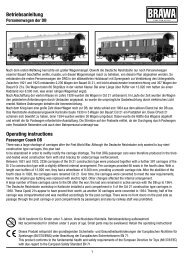
Entnahme der Lok aus der Verpackung (Fig. 1)<br />
Verpackung öffnen, Styropor mit Lokomotive herausziehen.<br />
Lokomotive über 2 Öffnungen an der Unterseite aus der Verpakkung<br />
drücken.<br />
Removing the locomotive from the packaging<br />
(Fig. 1)<br />
Open the packaging, pull out polystyrene together with the locomotive.<br />
Push locomotive from the packaging with the aid<br />
of the two openings on the underside of the packaging.<br />
Fig. 1<br />
5
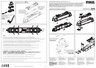
Zusatzbauteile montieren (Fig. 2)<br />
In der Verpackung sind zusätzliche Bauteile lose beigelegt.<br />
1 = 2x Bügelkupplung<br />
Werden die Bauteile aus dem Zurüstbeutel für Vitrinenmodelle<br />
montiert, ist die Lok nicht mehr für den Fahrbetrieb geeignet.<br />
2 = 4x Luftschlauch links 4 = 2x Heizschlauch<br />
3 = 4x Luftschlauch rechts 5 = 2x Kupplungsimitat<br />
Fitting additional parts (Fig. 2)<br />
Accessory parts have been loosely enclosed in the packaging.<br />
1 = 2x bow coupling<br />
If parts contained in the setting�up bag for showcase models are<br />
fitted, the locomotive is no longer suitable for running on tracks.<br />
2 = 4x air hose right 4 = 2x heating hose<br />
3 = 4x air hose left 5 = 2x imitation coupling<br />
Fig. 2<br />
6
Wartungsarbeiten<br />
Maintenance works<br />
1. Ölen (Fig. 3)<br />
Der Motor und die Lagerstellen der Radsätze können an den<br />
gekennzeichneten Punkten sparsam mit Öl der Modellbaubranche<br />
geölt werden. Zum Ölen des Motors ist das Gehäuse abzunehmen,<br />
siehe Seite 8 Punkt 2.<br />
1. Lubricating (Fig. 3)<br />
The engine and the wheelset bearings may be sparingly lubricated<br />
at the marked places with oil used for model making purposes.<br />
In order to lubricate the engine, remove the housing, compare<br />
page 12, item 2.<br />
Fig. 3<br />
Motor<br />
Motor<br />
Räder<br />
Wheels<br />
7
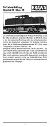
Wartungsarbeiten<br />
2. Gehäuse demontieren (Fig. 4, Seite 11)<br />
Führerstand (1) demontieren:<br />
4 Halteclipse (2) mittels eines kleinen Schraubendrehers nach<br />
oben ausclipsen. Führerstand nach oben herausziehen.<br />
Gehäuse vorn / hinten (3) demontieren:<br />
Gehäuse leicht zusammendrücken, dadurch werden die Halteclipse<br />
(4) ausgeclipst. Gehäuse nach oben abnehmen.<br />
3. Platine tauschen (Fig. 4, Seite 11)<br />
Gehäuse abnehmen, siehe Punkt 2.<br />
2 Befestigungsschrauben (5). Platine (7) leicht kippen und die<br />
Stromzufuhrkabel (8) ablöten. Verkabelung des Motors (9) an<br />
Platine ablöten.<br />
Hinweis:<br />
Bitte kennzeichnen Sie sich wie die Kabel angeschlossen waren –<br />
sonst falsche Fahrtrichtung.<br />
4. Beleuchtung<br />
Diese Lokomotive ist mit wartungsfreien Leuchtdioden ausgestattet.<br />
Bei einem eventuellen Defekt der Leuchtdioden wenden Sie<br />
sich bitte an Ihren Fachhändler oder den Hersteller.<br />
5. Motor tauschen (Fig. 4, Seite 11)<br />
Gehäuse und Platine abnehmen, siehe Punkte 2 und 3. Motorverkabelung<br />
(9) an Platine (7) ablöten. Befestigungsschrauben (8)<br />
vorne / hinten lösen und Gewichte (13 / 14) abnehmen. Drehgestellhalter<br />
(15) mit kleinem Schraubendreher ausclipsen. Schnecke<br />
(16) und Kardanwelle (17) aus Halterung entfernen. Drehgestell<br />
(18) nach unten abnehmen. Tank (19) an der Unterseite abziehen<br />
(ist mit Klebeband fixiert). Motorlagerungen (20) aus Bodenplatte<br />
(21) mit Schraubendreher nach oben ausknöpfen, Motor (22) mit<br />
beiden Motorlagerhälften herausnehmen.<br />
Achtung: Bei Ausbau des Motors auf Einbaulage achten –<br />
sonst falsche Fahrtrichtung.<br />
6. Wartungsarbeiten am oberen Getriebeteil<br />
(Fig. 4, Seite 11)<br />
Gehäuse und Platine demontieren, siehe Punkte<br />
2 bis 3. Befestigungsschrauben (12) vorne / hinten lösen und<br />
Gewichte abnehmen. Drehgestellhalter (15) mit kleinem Schraubendreher<br />
ausclipsen. Schnecke (16) und Kardanwelle (17) aus<br />
Halterung entfernen.<br />
8
7. Wartungsarbeiten an Radsätzen, unterem<br />
Getriebeteil und Haftreifen tauschen<br />
(Fig. 4, Seite 11)<br />
Hinweis für Wechselstrom�Ausführung:<br />
Vor dem Abnehmen der Getriebeabdeckung (23) muss der Schleifer<br />
(24) abgeschraubt werden.<br />
Gehäuse und Platine demontieren, siehe Punkte<br />
2 bis 3. Getriebeteil ausbauen, siehe Punkt 6. Stromzufuhrkabel (8)<br />
von der Platine (7) entfernen, Drehgestellhalter (15) mit kleinem<br />
Schraubendreher ausclipsen. Schnecke (16) und Kardanwelle (17)<br />
aus Halterung entfernen. Das gesamte Drehgestell (18) kann jetzt<br />
nach unten herausgezogen werden. Drehgestellblenden (25) an<br />
einer Seite vorsichtig lösen, Getriebeabdeckung (23) mit kleinem<br />
Schraubendreher anheben und ausclipsen, jetzt sind die Zahnräder<br />
(26) zugänglich und die Radsätze (27) entnehmbar. Nun lassen<br />
sich auch die Haftreifen (28) wechseln.<br />
8. Kupplungsnormschacht tauschen<br />
(Fig. 4, Seite 11)<br />
Normschacht�Stecker (29) herausziehen, Kupplungsnormschacht<br />
(30) mit Kupplung (31) entnehmen. Kupplung aus Kupplungsnormschacht<br />
herausziehen.<br />
9. Digitaldecoder tauschen (Fig. 4, Seite 11)<br />
Gehäuse demontieren, siehe Punkt 2.<br />
Digitaldecoder (33) abziehen und neuen einstecken.<br />
9
Wartungsarbeiten<br />
10. Umrüsten auf Digitalbetrieb (Fig. 4, Seite 11)<br />
Gleichstrom�Ausführung<br />
Gehäuse abnehmen, Blindstecker (34) abziehen und Digital<br />
�Decoder (33) einstecken.<br />
Den richtigen Einbau des Digitaldecoders und dessen<br />
Einsteckrichtung entnehmen Sie der Einbauvorschrift<br />
des Decoderherstellers.<br />
Wechselstrom�Ausführung<br />
Lokomotiven in Wechselstrom�Ausführung AC werden serienmäßig<br />
mit Premium�Digitaldecoder (33) ausge liefert. Der Decoder erkennt<br />
die Betriebsart (analog/digital) selbstständig. Soll der Decoder<br />
umprogramiert werden, liegt die Einbau� und Betriebsanleitung<br />
Premium�Digitaldecoder bei.<br />
Der Decoder ist Werkseitig auf Adresse 03 eingestellt.<br />
Funktionstastenbelegung für Soundmodelle<br />
F0 Licht an/aus<br />
F1 Sound an/aus<br />
F2 Signalhorn 1<br />
F3 Ventilator während der Fahrt an/aus<br />
F4 Schaltbares Schlusslicht<br />
F5 Kupplung/Entkupplung Geräusch<br />
F6 Rangiergang<br />
F7 Schmierpumpe<br />
F8 Kompressor<br />
F9 Sanden<br />
F10 Bremse<br />
F11 Signalhorn kurz<br />
F12 Schaltstufe hoch<br />
F13 Schaltstufe runter<br />
F14 Sicherheitsventil<br />
F15 Ventilator manuell ein/aus<br />
Hinweis:<br />
Wir bitten Sie genau darauf zu achten, wo und wie jedes Einzelteil<br />
montiert war. Die Einbaulage können Sie auch aus der Ersatzteilgrafik<br />
Seite 16 / 17 entnehmen.<br />
10
Fig. 4<br />
11
Maintenance works<br />
2. Dismantling housing (Fig. 4, Page15 )<br />
Dismantle driver’s cab (1):<br />
Using a small screwdriver, unclip the 4 mounting clips by lifting<br />
upwards. Remove the driver’s cab upwards.<br />
Dismantling the casing front / back (3):<br />
Slightly squeeze casing to release the mounting clips. Remove the<br />
casing upwards.<br />
3. Exchanging the circuit board (Fig. 4,Page 15)<br />
Remove casing, see item 2.<br />
Unscrew the two mounting screws. Slightly tip the circuit board (7)<br />
and unsolder the power supply cable (8). Unsolder the cable from<br />
the motor (9) to the circuit board.<br />
Note: Make a note of how the cables were soldered –<br />
otherwise direction may be wrong.<br />
4. Lighting<br />
This locomotive is fitted with maintenance�free light�emitting diodes.<br />
If a defect occurs in the light�emitting diodes, please contact<br />
your specialist dealer or the manufacturer.<br />
5. Exchanging the motor (Fig. 4, Page 15)<br />
Remove housing and circuit board, see item 2 and 3.<br />
Unsolder motor cables (9) from circuit board (7). Unscrew mounting<br />
screws (8) front / back and remove weights<br />
(13 / 14). Unclip bogie attachment (15) with a small screw driver.<br />
Remove endless screw (16) and cardan shaft (17) from their<br />
holders. Remove bogie (18) downwards. Pull tank (19) off the<br />
underside (fastened with adhesive tape). Using a screwdriver, push<br />
engine bearings (20) upwards from the bottom plate (21), remove<br />
engine (22) with both motor bearing halves.<br />
Caution: When removing the engine, please note the installation<br />
position, otherwise direction may be wrong.<br />
6. Maintenance work on the upper gear part<br />
(Fig. 4, Page 15)<br />
Dismantle casing and circuit board, see item 2 to 3. Unscrew<br />
mounting screws (12) front / back and remove weights. Unclip the<br />
bogie attachment (15) with a small screwdriver. Remove endless<br />
screw (16) and cardan shaft (17) from holder.<br />
12
7. Maintenance work on wheel sets, exchanging<br />
lower gear part and traction tires<br />
(Fig. 4, Page 15)<br />
Note on alternating current models:<br />
Bogie with pick�up is without propulsion. Before removing the gear<br />
cover (23) the pick�up (24) must be unscrewed.<br />
Dismantle casing and circuit board, see item 2 to 3. Dismantle<br />
gear part, see item 6. Remove power supply cable (8) from circuit<br />
board. Unclip the bogie attachment (15) with a small screwdriver.<br />
Remove endless screw (16) and cardan shaft (17) from holder.<br />
The whole bogie (18) can now be removed downwards. Release<br />
the bogie panels (25) carefully on one side, lift the gear cover<br />
(23) with a small screwdriver and unclip. Now you can access the<br />
tooth�wheels (26) and remove the wheel�sets (28). The traction<br />
tires can now be exchanged (28).<br />
8. Exchanging coupler pocket (Fig. 4, Page 15)<br />
Pull out coupler pocket pin (29), remove coupler pocket (30) with<br />
coupler (31). Pull out coupler from coupler pocket.<br />
9. Exchanging the digital decoder (Fig. 4, Page 15)<br />
Remove housing, see item 2.<br />
Pull out digital decoder (33) and insert new one.<br />
13
Maintenance works<br />
10. Conversion to digital operation (Fig. 4, Page 15)<br />
DC version<br />
Remove housing, pull off dummy connector (34) and insert digital<br />
decoder (33).<br />
Please consult the installation instructions issued by the<br />
decoder manufacturer for correct installation of the digital<br />
decoder and its insert direction.<br />
AC version<br />
The premium digital decoder (33) is standard for the alternating<br />
current (AC) locomotives models. The decoder independently<br />
identifies the operation type (analog/digital). Please refer to the<br />
enclosed installation and operation instructions “Premium Digital<br />
Decoder” in the event that the decoder needs to be reprogrammed.<br />
The decoder is set to address 03 in the factory.<br />
Function keys for Soundmodels<br />
F0 Light ON/OFF<br />
F1 Sound ON/OFF<br />
F2 Airhorn 1<br />
F3 Ventilator while driving ON/OFF<br />
F4 Switchable backlights<br />
F5 Coupling/Decoupling procedure<br />
F6 Shunting mode<br />
F7 Greasing<br />
F8 Compressor<br />
F9 Sanding<br />
F10 Brake<br />
F11 Airhorn short<br />
F12 Diesel notch up<br />
F12 Diesel notch up/down<br />
F13 Diesel notch down<br />
F14 Safety Valve<br />
F15 Ventilator manual ON/OFF<br />
Note:<br />
Please note exactly where and how each individual part was<br />
mounted. The mounting position is also indicated on the spart<br />
parts graph on page 16 / 17.<br />
14
Fig. 4<br />
15
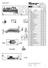
Ersatzteilliste<br />
Spare Parts List<br />
Vorn / Front Hinten / back<br />
Drehgestell siehe Seite 17<br />
Bogie see page 17<br />
16
Drehgestell hinten Bogie back<br />
Drehgestell vorn Bogie front<br />
17
Ersatzteilliste<br />
Spare Parts List<br />
Pos. Bennenung Description<br />
1 Gehäuse kpl. Body cpl<br />
6 Signalhorn Signal horn<br />
11 Platine mit LED, Kabel kurz PCB with LED, short wire<br />
12 Platine mit LED, Kabel lang PCB with LED, long wire<br />
13 Platine PCB<br />
14 Blindstecker Blind plug<br />
18 PremiumDigitaldecoder Premium digital decoder<br />
Sounddecoder Sounddecoder<br />
Lautsprecher Speaker<br />
19 Windabweiser Wind shield<br />
20 Griffstangen Führerhaus Handrail cabin<br />
23 Drehgestellhalter Bogie holder<br />
24 Schnecke kpl. Worm gear cpl.<br />
25 Lagerstein Bearing for Worm gear<br />
26 Scheibe Washer<br />
27 Puffer flach Buffer flat<br />
28 Puffer gewölbt Buffer round<br />
29 Griffstange gerade 4x Handrail straight 4x<br />
30 Griffstange gebogen 4x Handrail curved 4x<br />
31 Umlauf Main frame<br />
32 Kardanwelle Cardan shaft<br />
33 Motorhalter Motor holder<br />
34 Motor kpl. Motor cpl.<br />
35 Schrauben für Rahmen Screws for frame<br />
37 Tankabdeckung Tank cover<br />
38 Drehgestellblende Bogie side frame<br />
rechts hinten kpl. right back cpl.<br />
39 Drehgestellblende Bogie side frame<br />
links hinten kpl. left back cpl.<br />
43 Schraube für Getriebegehäuse Screw for gearbox<br />
18
Bestell Nr.<br />
Order no. 41220<br />
Artikelnummer/Article number<br />
41222 DC<br />
19<br />
41221 /<br />
41223 AC<br />
41224 /<br />
41226 DC<br />
41225 /<br />
41227 AC<br />
0000990.01 • • – –<br />
0010194.00 – – • •<br />
0000856.12 – – • •<br />
0000991.01 • • – –<br />
0001104.00 • • • •<br />
0001106.00 • • • •<br />
0010200.00 • • • •<br />
0010201.00 • – • –<br />
0005049.00 • • • •<br />
0005051.00 • • • •<br />
0005057.00 • • • •<br />
0000908.00 • • • •<br />
0000909.00 • • – –<br />
0000909.04 – – • •<br />
0000911.00 • • • •<br />
0001109.00 • • • •<br />
0000913.00 • • • •<br />
0000914.00 • • • •<br />
0000915.02 • • – –<br />
0000916.02 • • – –<br />
0000917.00 • • – –<br />
0000918.00 • • – –<br />
0000943.06 – – • •<br />
0001007.01 • • – –<br />
0001110.00 • • • •<br />
0000921.00 • • • •<br />
0001111.00 • • • •<br />
0000923.00 • • • •<br />
0000862.14 – – • •<br />
0000993.01 • • – –<br />
0000873.17 • • – –<br />
0000873.18 – – • •<br />
0000874.17 • • – –<br />
0000874.18 – – • •<br />
0001115.00 • • • •
Ersatzteilliste<br />
Spare Parts List<br />
Pos. Bennenung Description<br />
44 Schneckenrad Worm gear cpl.<br />
45 Zahnrad Gear<br />
47 Drehgestellblende Bogie side frame<br />
links vorne kpl. left front cpl.<br />
50 Drehgestellblende Bogie side frame<br />
rechts vorne kpl. right front cpl.<br />
51 Getriebeabdeckung Gearbox cover<br />
52 Normschacht Coupler pocket<br />
Normschacht Coupler pocket<br />
53 Federplättchen Spring for coupler<br />
54 Abdeckung für Normschacht Cover for coupler pocket<br />
58 Sandfallrohr rechts Sandpipe right<br />
59 Sandfallrohr links Sandpipe left<br />
60 Pin für Normschacht Pin for coupler pocket<br />
62 Schleifer Pic up shoe<br />
63 Schraube für Scheifer Screw for pic up shoe<br />
64 Getriebeabdeckung für m. Antrieb Gearbox cover<br />
65 Radsatz ohne Haftreifennut Wheelset without<br />
20<br />
preparing for traction tire<br />
66 Radsatz mit Haftreifennut Wheelset with<br />
67 Haftreifen Traction tire<br />
preparing for traction tire<br />
68 Radsatz ohne Antreib Wheel set without<br />
gear wheel<br />
70 Bügelkupplung Coupler<br />
70 Zurüstbeutel Extra parts<br />
71 Scheibenwischer Wiper<br />
75 Schrauben für Platine Screw for PCB
Bestell Nr.<br />
Order no. 41220<br />
Artikelnummer/Article number<br />
41222 DC<br />
21<br />
41221 /<br />
41223 AC<br />
41224 /<br />
41226 DC<br />
41225 /<br />
41227 AC<br />
0001116.00 • • • •<br />
0001117.00 • • • •<br />
0000877.17 • • – –<br />
0000877.18 – – • •<br />
0000878.17 • • – –<br />
0000878.18 – – • •<br />
0000879.01 – – – –<br />
0000879.11 • • – –<br />
0000928.03 • • – –<br />
0000880.01 – – • •<br />
0000780.00 • • • •<br />
0000881.01 – – • •<br />
0000881.11 • • – –<br />
0000932.02 – – • •<br />
0000932.11 • • – –<br />
0000933.02 – – • •<br />
0000933.11 • • – –<br />
0000882.11 • • – –<br />
2225 – • – •<br />
0000834.00 – • – •<br />
0000893.01 – – – •<br />
0000893.10 – • – –<br />
0000934.00 • – • –<br />
0001015.00 – • – •<br />
0000935.00 • – • –<br />
0001016.00 – • – •<br />
0002129.00 • • • •<br />
0001017.00 – • – •<br />
0000729.00 • • • •<br />
0000748.00 • • • •<br />
0000884.12 • • – –<br />
0000884.13 – – • •<br />
0000937.00 • • • •
Ersatzteilliste<br />
Spare Parts List<br />
Pos. Bennenung Description<br />
81 Pin für Normschacht Drehgestell<br />
mit Schleifer<br />
Pin for coupler pocket<br />
82 Kühlleitung am Tank lang Tank pipe long<br />
86 Schraube für Lautsprecher Screw for speaker<br />
87 Sonnenblende Sunshade<br />
88 Trittstufe am Tank Step at tank<br />
89 Geländer Handrail<br />
90 Geländer kurz links Handrail short left<br />
91 Geländer lang links Handrail long left<br />
92 Trittblech am Umlauf Step plate main frame<br />
93 Puffer rechteckig Buffer square<br />
94 Geländer kurz rechts Handrail short right<br />
95 Geländer lang rechts Handrail long right<br />
Wichtiger Hinweis!<br />
Bei der Bestellung von Ersatzteilen muss die Bestell�Nr. und die<br />
Be nennung angegeben werden. Ist dies nicht der Fall, kann die<br />
Bestellung nicht bearbeitet werden.<br />
Important notice!<br />
When ordering spare parts you must always state the order number<br />
and give the description. If you do not do this, the order cannot<br />
be processed.<br />
Bestellbeispiel:<br />
Position (34), Motor = 0001111.00, Motor<br />
Order example:<br />
Position (34), Motor = 0001111.00, Motor<br />
22
Bestell Nr.<br />
Order no. 41220<br />
Artikelnummer/Article number<br />
41222 DC<br />
23<br />
41221 /<br />
41223 AC<br />
41224 /<br />
41226 DC<br />
41225 /<br />
41227 AC<br />
0001037.00 – – – •<br />
0001037.05 – • – –<br />
0000889.02 • • • •<br />
0000890.02 • • • •<br />
0001118.00 • • • •<br />
0000939.11 – – • •<br />
0010195.00 • • – –<br />
0000938.01 – – • •<br />
0000950.03 – – • •<br />
0010196.00 – – • •<br />
0010197.00 – – • •<br />
0010198.00 – – • •<br />
0000892.00 – – • •<br />
0010508.00 – – • •<br />
0010509.00 – – • •
Maßstabs� und originalgetreue Kleinmodelle für<br />
erwachsene Sammler.<br />
Scale and true to original small�sized model for adult<br />
collectors.<br />
Zum Betrieb des vorliegenden Produkts darf als Spannungsquelle<br />
nur ein nach VDE 0551/EN 60742 gefertigter<br />
Spielzeug�Transformator verwendet werden.<br />
Only a toy transformer produced compliant with VDE<br />
0551/EN 60742 may be used as a voltage source to<br />
operate this product.<br />
Elektro� und Elektronikaltgeräte dürfen nicht in den<br />
Hausmüll gelangen. Sie müssen entsprechend der<br />
jeweils gültigen Länderrichtlinien fachgerecht entsorgt<br />
werden.<br />
Electrical equipment may not reach to domestic waste.<br />
According to the current terms of the country reference<br />
the electrical eqipment must professional disposed.<br />
Brawa Artur Braun Modellspielwarenfabrik GmbH & Co.<br />
Uferstraße 26�28 · D�73630 Remshalden<br />
Telefon +49 (0)7151 � 979 35 68<br />
Telefax +49 (0)7151 � 746 62<br />
www.brawa.de<br />
24<br />
41220.50.100 / 07 12 – BRA