Print Katalog - Rosenberger Hochfrequenztechnik
Print Katalog - Rosenberger Hochfrequenztechnik
Print Katalog - Rosenberger Hochfrequenztechnik

Erfolgreiche ePaper selbst erstellen
Machen Sie aus Ihren PDF Publikationen ein blätterbares Flipbook mit unserer einzigartigen Google optimierten e-Paper Software.
<strong>Rosenberger</strong>HSD ® Connectors<br />
High Speed Data Connectors
About <strong>Rosenberger</strong> . . . . . . . . . . . . . . . . . . . . . . . . . . . . . . . . . . . . . . . . . . . . . . . . . . 3<br />
Product Overview . . . . . . . . . . . . . . . . . . . . . . . . . . . . . . . . . . . . . . . . . . . . . . . . . . . . 4<br />
<strong>Rosenberger</strong>HSD ® Connectors - The Concept . . . . . . . . . . . . . . . . . . . . . . . . . . . . . . 5<br />
Pinning . . . . . . . . . . . . . . . . . . . . . . . . . . . . . . . . . . . . . . . . . . . . . . . . . . . . . . . . . . . 12<br />
Quality and Environment. . . . . . . . . . . . . . . . . . . . . . . . . . . . . . . . . . . . . . . . . . . . . . 13<br />
Number Designation . . . . . . . . . . . . . . . . . . . . . . . . . . . . . . . . . . . . . . . . . . . . . . . . . 14<br />
Cables, Platings . . . . . . . . . . . . . . . . . . . . . . . . . . . . . . . . . . . . . . . . . . . . . . . . . . . . . 15<br />
Technology . . . . . . . . . . . . . . . . . . . . . . . . . . . . . . . . . . . . . . . . . . . . . . . . . . . . . . . . 16<br />
Codings . . . . . . . . . . . . . . . . . . . . . . . . . . . . . . . . . . . . . . . . . . . . . . . . . . . . . . . . . . 17<br />
PCB Connectors . . . . . . . . . . . . . . . . . . . . . . . . . . . . . . . . . . . . . . . . . . . . . . . . . . . . 19<br />
Cable Assemblies . . . . . . . . . . . . . . . . . . . . . . . . . . . . . . . . . . . . . . . . . . . . . . . . . . . 20<br />
Codings, Cable Up. . . . . . . . . . . . . . . . . . . . . . . . . . . . . . . . . . . . . . . . . . . . . . . . . . . 23<br />
PCB Connectors, Cable Up . . . . . . . . . . . . . . . . . . . . . . . . . . . . . . . . . . . . . . . . . . . . 24<br />
Cable Assemblies, Cable Up . . . . . . . . . . . . . . . . . . . . . . . . . . . . . . . . . . . . . . . . . . . 25<br />
Cable Connectors, Dimensions . . . . . . . . . . . . . . . . . . . . . . . . . . . . . . . . . . . . . . . . . 27<br />
Panel Piercings - PCB Layouts . . . . . . . . . . . . . . . . . . . . . . . . . . . . . . . . . . . . . . . . . 28<br />
Index. . . . . . . . . . . . . . . . . . . . . . . . . . . . . . . . . . . . . . . . . . . . . . . . . . . . . . . . . . . . . 29<br />
Contents<br />
<strong>Rosenberger</strong> <strong>Hochfrequenztechnik</strong> GmbH & Co. KG, POB 1260, D- 84526 Tittmoning, Tel. +49- 86 84- 18- 0, Fax. +49- 86 84- 18- 499, www.rosenberger.de<br />
1
Contents<br />
2<br />
<strong>Rosenberger</strong> <strong>Hochfrequenztechnik</strong> GmbH & Co. KG, POB 1260, D- 84526 Tittmoning, Tel. +49- 86 84- 18- 0, Fax. +49- 86 84- 18- 499, www.rosenberger.de
About <strong>Rosenberger</strong><br />
<strong>Rosenberger</strong>HSD ®<br />
1<strong>Rosenberger</strong>HSD ®<br />
Company Profile Unternehmensprofil<br />
<strong>Rosenberger</strong>, founded in 1958, is one of the leading manufacturers of<br />
high- frequency coaxial connectors worldwide. Our products play a keyrole<br />
in many high- tech industries, e.g. telecommunication, automotive<br />
electronics, test & measurement applications, medical electronics, data systems,<br />
etc.<br />
The product range includes high- frequency coaxial connectors, automotive<br />
connectors, RF- test & measurement products and wireless terminal components<br />
for wireless applications, mainly in consumer electronics or mobile<br />
phone terminals. In addition, fiber optic products as well as cable assemblies<br />
are also available.<br />
Our headquarters - with research & development, production and administrative<br />
departments - are located in Fridolfing, in the south- eastern part<br />
of Bavaria, Germany. Approximately 2,500 employees in our headquarters,<br />
manufacturing plants and sales offices in Europe, Asia as well as in North<br />
and South America take care of development, production and sales of our<br />
products.<br />
<strong>Rosenberger</strong> is certified according to ISO/TS 16949:2002, ISO 9001 and ISO<br />
14001.<br />
<strong>Rosenberger</strong>, gegründet 1958, zählt zu den weltweit führenden Herstellern<br />
von Hochfrequenz- Koaxial- Steckverbindern und spielt eine Schlüsselrolle<br />
in vielen High- Tech- Branchen, z. B. in der Telekommunikation, der<br />
Automobil- Elektronik, in der Datentechnik, in der industriellen Messtechnik<br />
oder in der Medizinelektronik.<br />
Das Produktspektrum umfasst Hochfrequenz- Koaxialsteckverbinder,<br />
Steckverbinder für die Automobil- Elektronik, HF- Messtechnik- Produkte<br />
sowie Mobilfunk- Komponenten für Wireless- Anwendungen. Hinzu kommen<br />
Fiber- Optik- Produkte und der Bereich Kabel- Konfektionierung.<br />
Unser Stammwerk - mit Forschung & Entwicklung, Produktion und Zentralstellen<br />
- befindet sich in Fridolfing (Oberbayern) im bayerischen Voralpenland.<br />
Weltweit sorgen mehr als 2500 Mitarbeiter in unserem<br />
Stammwerk, den Fertigungs- und Montage- Standorten sowie unseren<br />
Vertriebsniederlassungen in Europa, Asien sowie Nord- und Südamerika<br />
für Entwicklung, Fertigung und Verkauf unserer Produkte.<br />
<strong>Rosenberger</strong> ist zertifiziert nach ISO/TS 16949:2002, ISO 9001 und ISO<br />
14001.<br />
Additional <strong>Rosenberger</strong> catalogs Weitere <strong>Rosenberger</strong>- <strong>Katalog</strong>e<br />
– High Frequency Coaxial Connectors and Accessories<br />
– Test, Measurement & Calibration Products<br />
– Reverse Polarity Connectors<br />
– FMC: Series FMC<br />
– SnapN: Series SnapN<br />
– QN: Series QN<br />
– Automotive Connectors<br />
– Wireless Terminal Components<br />
– Hochfrequenz- Koaxial- Steckverbinder und Zubehör<br />
– HF- Messtechnik- & Kalibrier- Produkte<br />
– Reverse Polarity- Steckverbinder<br />
– FMC: Steckverbinder- Serie FMC<br />
– SnapN: Steckverbinder- Serie SnapN<br />
– QN: Steckverbinder- Serie QN<br />
– Automotive- Steckverbinder<br />
– Wireless Terminal Components<br />
<strong>Rosenberger</strong> <strong>Hochfrequenztechnik</strong> GmbH & Co. KG, POB 1260, D- 84526 Tittmoning, Tel. +49- 86 84- 18- 0, Fax. +49- 86 84- 18- 499, www.rosenberger.de<br />
3<br />
1
<strong>Rosenberger</strong>HSD ® Product Overview<br />
Product Overview<br />
Product Overview Produktüberblick<br />
<strong>Rosenberger</strong> has developed a homogeneous impedance controlled interconnect<br />
system for High Speed Data (<strong>Rosenberger</strong>HSD ® ) applications. This<br />
is a high performance digital system for low voltage differential signals that<br />
prevents interference by crosstalk and external sources. Performance is<br />
achieved by using an optimized shield concept with complete braid connection<br />
to the outer contact of the connector.<br />
The <strong>Rosenberger</strong>HSD ® interconnect system is exclusively dedicated to the<br />
automotive market for LVDS camera, USB and IEEE 1394 applications. The<br />
HSD system features mechanical keying, latching, colour code options and<br />
minimum size to satisfy worldwide automotive requirements. <strong>Rosenberger</strong><br />
HSD is a 100 Ω fully shielded interconnect system that can use shielded<br />
twisted quad cables.<br />
4<br />
Das von <strong>Rosenberger</strong> entwickelte impedanzkontrollierte, 100 Ω-Steckverbindungs-<br />
System für High Speed Data- Anwendungen (<strong>Rosenberger</strong>HSD ® )<br />
überträgt LVDS- (Low Voltage Differential Signal)Signale in erstklassiger<br />
Qualität, Störsignale durch interne Signaleffekte ("Crosstalk") und externe<br />
Störquellen werden verhindert. Die hohe Übertragungsqualität wird<br />
erreicht durch ein optimiertes Schirmungskonzept - das Kabelgeflecht ist<br />
mit dem Außenleiter des Steckverbinders vollständig verbunden.<br />
Das <strong>Rosenberger</strong>HSD ® - Steckverbinder- System wurde speziell für Anwendungen<br />
in der Automobil- Elektronik entwickelt, beispielsweise LVDS-<br />
Kameras, USB oder IEEE 1394- Applikationen. Mit dem ausgereiften<br />
Kodierungs- und Verriegelungssystem sowie den minimalen Produktabmessungen<br />
erfüllt die Serie HSD- Steckverbinder die hohen Anforderungen<br />
der Automobilindustrie. Das geschirmte Steckverbinder- System ist für 4polige<br />
geschirmte Kabelanwendungen geeignet.<br />
Product Range Produktspektrum<br />
– PCB connectors<br />
– 4- pole cable assemblies<br />
– Leiterplatten- Steckverbinder<br />
– 4- polige Kabelleitungen<br />
Application Fields Anwendungsfelder<br />
– Automotive electronics, e.g. USB connections, LVDS cameras,<br />
IEEE 1394 applications<br />
– Telecom industries, e.g. radio base stations<br />
– Digital infotainment electronics<br />
– Digital symmetrical networks<br />
– Automobil- Elektronik, z. B. USB- Verbindungen, LVDS- Kameras,<br />
IEEE 1394- Anwendungen<br />
– Mobilfunk- Basisstationen<br />
– Digitale Infotainment- Anwendungen<br />
– Digitale symmetrische Netzwerke<br />
<strong>Rosenberger</strong> <strong>Hochfrequenztechnik</strong> GmbH & Co. KG, POB 1260, D- 84526 Tittmoning, Tel. +49- 86 84- 18- 0, Fax. +49- 86 84- 18- 499, www.rosenberger.de
<strong>Rosenberger</strong>HSD ® Connectors - The Concept<br />
2<strong>Rosenberger</strong>HSD ®<br />
<strong>Rosenberger</strong>HSD® Connectors - The Concept<br />
The <strong>Rosenberger</strong>HSD ® concept –<br />
Gbit/s data transfer on copper interconnects<br />
The <strong>Rosenberger</strong>HSD ® system for transmitting data streams at high bit<br />
rates is based on the star- quad principle and was originally devised for the<br />
automobile industry. Two differential signal pairs are used, so the uniform<br />
100- Ω system can transmit data streams not only to LVDS but also to USB,<br />
ethernet, GVIF and IEEE 1394 specifications.<br />
High- grade cables satisfy the demands of the automobile industry for electromagnetic<br />
shielding. The electrical characteristics of the cable are<br />
described in terms of bandwidth/length, shielding effectiveness and cable<br />
insertion loss as a function of temperature.<br />
Differential signal transfer<br />
For communication on a line with only one<br />
signal conductor, information is transmitted<br />
in the form of the potential of the signal<br />
conductor referred to ground. This is<br />
very sensitive to shifts in ground potential,<br />
directly corrupting the communication.<br />
On a balanced line the communication is<br />
transmitted as a potential difference<br />
between two signal conductors. In this<br />
case a change of the ground potential<br />
through static or dynamic ground currents<br />
has the same effect on both signal conductors,<br />
is eliminated in the receiver, and consequently<br />
will not influence the transmitted<br />
signal (Fig. 1).<br />
The star- quad cable – Star- quad topology<br />
The HSD system bears two balanced wire<br />
pairs in one cable. The two pairs are surrounded<br />
by a joint shield. The single insulated<br />
conductors are configured as a star<br />
quad and jointly stranded. Two diagonally<br />
opposite conductors in the star quad form<br />
a differential wire pair (Fig. 2). In this way<br />
there is always a balanced pair on the virtual<br />
ground plane of what is the second<br />
pair. This results in high crosstalk attenuation,<br />
and at the same time the cable is as<br />
compact as possible.<br />
Maximum crosstalk attenuation is necessary<br />
to be able to transmit broadband data<br />
streams on the two wire pairs independently<br />
of one another and without harmful<br />
interference between them.<br />
Fig. 1: The interference shifts the<br />
potential of both conductors to<br />
the same degree. This commonmode<br />
interference is ignored by<br />
the receiver.<br />
Fig. 2: Arrangement of wires of<br />
two differential lines in a shielded<br />
star quad<br />
<strong>Rosenberger</strong>HSD ®<br />
Das <strong>Rosenberger</strong>HSD ® -Konzept –<br />
Datenübertragung von Gbit/s auf Kupferkabeln<br />
Das <strong>Rosenberger</strong>HSD ® - System zur Übertragung hochbitratiger Datenströme<br />
basiert auf dem Sternviererkonzept und wurde ursprünglich für die<br />
Automobilindustrie entwickelt. Das System stellt zwei differentielle Signalpaare<br />
zur Verfügung, somit können Datenströme nicht nur nach LVDS- ,<br />
sondern auch nach USB- , Ethernet- , GVIF- und IEEE 1394- Spezifikation<br />
über dieses einheitliche 100 Ω- System übertragen werden. Die hochwertig<br />
abgeschirmten Kabel erfüllen die hohen Anforderungen der Automobilindustrie<br />
in Bezug auf die elektromagnetische Abstrahlung. Die elektrischen<br />
Eigenschaften des Kabels werden hinsichtlich der Bandbreite- Länge- Relation,<br />
der Schirmdämpfung und der Temperaturabhängigkeit der Kabeleinfügungsdämpfung<br />
beschrieben.<br />
Bild 1: Der Störer verschiebt<br />
beide Leiterpotentiale in gleichem<br />
Maße. Diese Gleichtaktstörung<br />
wird vom Empfänger<br />
ignoriert.<br />
Differentielle Signalübertragung<br />
Bei der Nachrichtenübertragung über eine<br />
Leitung mit nur einem Signalleiter wird die<br />
Information in Form des Potentials des<br />
Signalleiters bezüglich Masse übertragen.<br />
Diese Art der Informationsübertragung<br />
reagiert sehr empfindlich auf Verschiebungen<br />
des Massepotentials, welche die<br />
Nachricht direkt verfälschen.<br />
Auf der symmetrischen Leitung wird die<br />
Nachricht als Potentialdifferenz zwischen<br />
zwei Signalleitern übertragen. Eine Änderung<br />
des Massepotentials durch statisch<br />
oder dynamisch fließende Masseströme<br />
wirkt in diesem Fall auf beide Signalleiter<br />
in gleichem Maße, wird im Empfänger eliminiert<br />
und hat daher keinen Einfluss auf<br />
das übertragene Signal (Bild 1).<br />
Das Sternviererkabel – Die Sternvierer- Topologie<br />
Bild 2: Die Anordnung der<br />
Adern zweier differentieller Leitungen<br />
im geschirmten<br />
Sternvierer<br />
Das HSD- System trägt zwei symmetrische<br />
Leitungspaare in einem Kabel. Beide Paare<br />
sind von einem gemeinsamen Schirm<br />
umgeben. Die einzeln isolierten Leiter sind<br />
in Form eines Sternvierers angeordnet und<br />
gemeinsam verseilt. Zwei einander im<br />
Sternvierer diagonal gegenüberliegende<br />
Leiter bilden ein differentielles Aderpaar<br />
(Bild 2). Damit liegt ein symmetrisches<br />
Paar immer in der virtuellen Masseebene<br />
des jeweils zweiten Paars. Dies ermöglicht<br />
die Realisierung einer hohen Übersprechdämpfung<br />
bei gleichzeitig größtmöglicher<br />
Kompaktheit des Kabels. Eine möglichst<br />
hohe Übersprechdämpfung ist notwendig,<br />
um auf beiden Leitungspaaren voneinander<br />
unabhängig breitbandige Datenströme<br />
ohne schädliche gegenseitige<br />
Störungen übertragen zu können.<br />
<strong>Rosenberger</strong> <strong>Hochfrequenztechnik</strong> GmbH & Co. KG, POB 1260, D- 84526 Tittmoning, Tel. +49- 86 84- 18- 0, Fax. +49- 86 84- 18- 499, www.rosenberger.de<br />
5<br />
2
<strong>Rosenberger</strong>HSD ®<br />
6<br />
Fig. 3a: Configuration of the star<br />
quad for unidirectional data<br />
transfer on the wire pairs<br />
Fig. 3c: Configuration of the star<br />
quad for data transfer on one<br />
and DC on the other wire pair<br />
The following configurations of the wire pairs of an HSD system are<br />
possible:<br />
– Fig. 3a: unidirectional data transfer,<br />
– Fig. 3b: bidirectional data transfer,<br />
– Fig. 3c: data transfer on pair 1, DC on pair 2,<br />
– Fig. 3d: DC on pair 2, data transfer on pair 1:<br />
DC- forward to pair 2, DC- return to shielding braid<br />
HSD connectors<br />
To ensure high crosstalk attenuation<br />
between differential pairs, the star- quad<br />
constellation is maintained on the connector<br />
interface. The cable shield is connected<br />
by a slotted contact, as widely used for<br />
coaxial lines. The connector faces of the<br />
HSD jack and plug are shown in Fig. 4.<br />
Both the signal pins and the outer conductor<br />
sleeve are connected to the cable by<br />
crimp contacts to produce high reliability<br />
and allow automated assembly.<br />
Bild 3a: Beschaltung des Sternvierers<br />
zur unidirektionalen<br />
Übertragung von Daten auf den<br />
Datenpaaren<br />
Bild 3c: Beschaltung des Sternvierers<br />
zur Übertragung von<br />
Daten auf einem, und Gleichstrom<br />
auf dem zweiten Aderpaar<br />
Fig. 4: Interface of HSD jack and<br />
plug<br />
<strong>Rosenberger</strong>HSD ® Connectors - The Concept<br />
Fig. 3b: Configuration of the star<br />
quad for bidirectional data transfer<br />
on the wire pairs<br />
Fig. 3d: Configuration of the star<br />
quad for data transfer on one<br />
and DC on pair 2<br />
Bild 3b: Beschaltung des Sternvierers<br />
zur bidirektionalen Übertragung<br />
von Daten auf den<br />
Datenpaaren<br />
Folgende Beschaltungen der Leitungspaare des HSD- Systems sind<br />
möglich:<br />
– Bild 3a: unidirektionale Datenübertragung<br />
– Bild 3b: bidirektionale Datenübertragung<br />
– Bild 3c: Datenübertragung auf Paar 1, Gleichstrom auf Paar 2<br />
– Bild 3d: Gleichstrom auf Paar 2, Datenübertragung auf Paar 1:<br />
DC vorwärts auf Paar 2, Rückfluß auf Schirm<br />
Bild 4: Interface von HSD-<br />
Kuppler und Stecker<br />
Bild 3d: Beschaltung des Sternvierers<br />
zur Übertragung von<br />
Daten auf einem, und Gleichstrom<br />
auf Paar 2<br />
HSD- Steckverbinder<br />
Zur Sicherstellung einer hohen Übersprechdämpfung<br />
zwischen den differentiellen<br />
Paaren wird die Sternviererkonstellation<br />
auch im Interface der Steckverbinder<br />
beibehalten. Die Kontaktierung<br />
des Kabelschirms übernimmt eine<br />
geschlitzte Kontaktbuchse, wie sie bei<br />
Koaxialleitungen weit verbreitet ist. Die<br />
Steckgesichter von HSD- Kuppler und Stecker<br />
sind in Bild 4 gezeigt.<br />
Sowohl die Signalpins als auch die Außenleiterhülse<br />
sind mit dem Kabel über Crimpkontakte<br />
verbunden, um eine hohe<br />
Zuverlässigkeit zu erzielen und ein automatisiertes<br />
Montagekonzept umsetzen zu<br />
können.<br />
<strong>Rosenberger</strong> <strong>Hochfrequenztechnik</strong> GmbH & Co. KG, POB 1260, D- 84526 Tittmoning, Tel. +49- 86 84- 18- 0, Fax. +49- 86 84- 18- 499, www.rosenberger.de
<strong>Rosenberger</strong>HSD ® Connectors - The Concept<br />
Solid expertise and many years of experience in the development and manufacture<br />
of coaxial RF connectors for the automobile industry (HF- FAKRA<br />
connectors) went into the creation of the <strong>Rosenberger</strong>HSD ® system.<br />
The HSD system is characterized by the following:<br />
– primary and secondary lock,<br />
– crimp connection on signal and outer<br />
conductor,<br />
– insertion funnel on jack inner conductors,<br />
– protection of plug pins by plastic<br />
domes,<br />
– cable retention force of 200 N,<br />
– polarization feature effectiveness of<br />
min. 80 N (12 codings to exclude misconnects<br />
are possible on the plastic<br />
housing).<br />
Results of electrical measurements<br />
The measured results impressively illustrate the suitability of the star- quad<br />
concept.<br />
TDR/TDT measurement<br />
The inherent rise time was limited to 80 ps<br />
by a rise time limiter on a conventional TDR<br />
oscilloscope (CSA 8000).<br />
The measured results are shown in Fig. 6.<br />
The two curves (C1, C2) illustrated at the<br />
top show the TDR profile for application<br />
through an adapter board, approx. 20 cm<br />
of HSD cable and a further adapter board.<br />
Even for the short rise of 80 ps, the deviations<br />
from the rated characteristic impedance<br />
of 100 Ω remain less than 10%. The<br />
curves (C3, C4) illustrated at the bottom are<br />
the measured shape of the transmitted<br />
pulse. The lack of ripple in the signal is a<br />
further clear indication of the very small<br />
amount of reflection of the signal path.<br />
Fig. 5: Cross section through a<br />
joined HSD pair<br />
Fig. 6: TDR (top) and TDT (bottom)<br />
measurement on a short<br />
HSD line<br />
<strong>Rosenberger</strong>HSD ®<br />
Das fundierte Know- how und langjährige Erfahrung in Entwicklung und<br />
Herstellung von HF- Koaxialsteckverbindern für die Automobilindustrie<br />
(HF- FAKRA- Steckverbinder) sind in die Entwicklung des <strong>Rosenberger</strong>HSD<br />
® - Systems eingeflossen.<br />
Das HSD- System zeichnet sich durch folgende Eigenschaften aus:<br />
– Primär- und Sekundärsicherung<br />
– Crimpverbindung an Signal- und<br />
Außenleiter<br />
– Einführtrichter an den Kupplerinnenleitern<br />
Bild 5: Schematischer Teilschnitt<br />
durch ein gestecktes<br />
HSD- Paar<br />
– Schutz der Steckerpins durch Kunststoff-<br />
Dome<br />
– Kabelabzugskraft von 200 N<br />
– Kodierungseffizienz von min. 80 N<br />
(am Kunststoffgehäuse sind<br />
12 Kodierungen möglich, die Fehlsteckungen<br />
ausschließen)<br />
Ergebnisse der elektrischen Messungen<br />
Die Messergebnisse stellen die Eignung des Sternviererkonzepts eindrucksvoll<br />
unter Beweis.<br />
Bild 6: TDR- (oben) und TDT-<br />
(unten) Messung an einer kurzen<br />
HSD- Leitung<br />
TDR/TDT- Messung<br />
Hierfür wurde an einem handelsüblichen<br />
TDR- Oszilloskop (CSA 8000) die Eigenanstiegszeit<br />
durch Risetime- Limiter auf 80 ps<br />
begrenzt.<br />
Die Messergebnisse werden in Bild 6<br />
gezeigt. Die beiden im Bild oben abgebildeten<br />
Kurven (C1, C2) zeigen das TDR-<br />
Profil beim Durchlaufen einer Adapterplatine,<br />
ca. 20 cm HSD- Kabel und einer weiteren<br />
Adapterplatine. Selbst bei der kurzen<br />
Anstiegszeit von 80 ps bleiben die Abweichungen<br />
vom Nennwellenwiderstand von<br />
100 Ω unter 10%. Die im Bild unten<br />
gezeigten Kurven (C3, C4) geben die<br />
gemessene Form des transmittierten Pulses<br />
wieder. Die geringe Welligkeit des Signals<br />
ist ein weiteres deutliches Indiz für<br />
das geringe Maß an Reflexionen des Signalpfads.<br />
<strong>Rosenberger</strong> <strong>Hochfrequenztechnik</strong> GmbH & Co. KG, POB 1260, D- 84526 Tittmoning, Tel. +49- 86 84- 18- 0, Fax. +49- 86 84- 18- 499, www.rosenberger.de<br />
7<br />
2
<strong>Rosenberger</strong>HSD ®<br />
8<br />
Measurement of eye pattern diagrams<br />
Measurement of eye pattern diagrams is<br />
performed by a setup in which a source<br />
generates a pseudo- random bit stream<br />
that is fed into a transmission channel.<br />
Once the signal has passed the channel,<br />
the eye, i.e. the pattern of the bit stream, is<br />
displayed and rated on the high- speed<br />
sampling oscilloscope synchronously to the<br />
fed- in bit stream.<br />
The HSD system enables transfer of a data<br />
stream with a bit rate of 800 Mbit/s over a<br />
distance of 10 m.<br />
RF simulations during the development<br />
phase produced excellent electrical features<br />
without unnecessary compromises.<br />
The eye pattern diagram (Fig. 8) is an<br />
impressive demonstration of the high signal<br />
transmission quality of the HSD system.<br />
For this measurement a bit stream was<br />
transmitted over an HSD line with a length<br />
of 1.35 m at a rate of 3.2 Gbit/s. The<br />
impact of the adapter boards on the overall<br />
electrical performance is included in the<br />
measurement results.<br />
For all measurements the edges generated<br />
in the source exhibit a negligible rise time<br />
compared to the duration of a bit and the<br />
fed- in bit stream shows no overshoot.<br />
To illustrate the transmitted bit repetition<br />
frequency as a function of the length of the<br />
cable, measurements of the eye pattern<br />
diagrams were conducted on HSD cables of<br />
different lengths. The measure of the quality<br />
of signal transmission is the maximum<br />
relative eye opening of the bit stream after<br />
transmission.<br />
The result clearly shows that the transmitted<br />
bandwidth is limited by the influence of<br />
the cable. No significant limiting as a result<br />
of the connectors can be observed, even at<br />
several Gbit/s.<br />
Fig. 7: Measurement of the eye<br />
pattern diagram on an HSD line<br />
with a length of 10 m at<br />
800 Mbit/s<br />
Fig. 8: Measurement of the eye<br />
pattern diagram on an HSD line<br />
with a length of 1.35 m at<br />
3200 Mbit/s<br />
Fig. 9: Maximum relative eye<br />
opening for transmission on HSD<br />
lines of different lengths<br />
<strong>Rosenberger</strong>HSD ® Connectors - The Concept<br />
Bild 7: Messung des Augendiagramms<br />
an einer HSD- Leitung<br />
mit einer Länge von 10 m bei<br />
800 Mbit/s<br />
Bild 8: Messung des Augendiagramms<br />
an einer HSD- Leitung<br />
mit einer Länge von 1,35 m bei<br />
3200 Mbit/s<br />
Bild 9: Maximale relative<br />
Augenöffnung bei der Übertragung<br />
HSD- Leitungen unterschiedlicher<br />
Längen<br />
Messungen von Augendiagrammen<br />
Die Messung von Augendiagrammen<br />
erfolgt mittels eines Messaufbaus, bei dem<br />
ein Generator einen Pseudozufallsbitstrom<br />
erzeugt, welcher in einen Übertragungskanal<br />
eingespeist wird. Nachdem das Signal<br />
den Kanal durchlaufen hat, wird das Auge,<br />
d.h. die Form des Bitstroms, am schnellen<br />
Abtastoszilloskop synchron zum eingespeisten<br />
Bitstrom dargestellt und bewertet.<br />
Mit dem HSD- System ist die Übertragung<br />
eines LVDS- Bitstroms mit einer Bitrate von<br />
800 Mbit/s über eine Entfernung von 10 m<br />
möglich.<br />
Durch laufende designbegleitende Hochfrequenzsimulationen<br />
in der Entwicklungsphase<br />
wurden überragende<br />
elektrische Eigenschaften ohne unnötige<br />
Kompromisse erreicht. Das Augendiagramm<br />
(Bild 8) zeigt eindrucksvoll die<br />
hohe Signalübertragungsqualität des<br />
HSD- Systems.<br />
Für die Messung wurde ein Bitstrom mit<br />
einer Datenrate von 3,2 Gbit/s über eine<br />
Länge von 1,35 m übertragen. Der Einfluss<br />
des Übergangs vom Kabel in die Adapterplatinen<br />
ist in der Messung berücksichtigt.<br />
In allen Messungen besitzen die in der<br />
Quelle erzeugten Flanken eine im Vergleich<br />
zur Dauer eines Bits vernachlässigbare<br />
Anstiegszeit, der eingekoppelte Bitstrom<br />
zeigt kein Überschwingen.<br />
Zur Darstellung der übertragbaren Bitfolgefrequenz<br />
in Abhängigkeit von der Länge<br />
des Kabels wurden Messungen der<br />
Augendiagramme an HSD- Kabeln unterschiedlicher<br />
Längen durchgeführt. Als Maß<br />
für die Güte der Signalübertragung dient<br />
die maximale relative Augenöffnung des<br />
Bitstroms nach der Übertragung.<br />
Das Ergebnis zeigt eindeutig, dass die<br />
übertragbare Bandbreite durch den Einfluss<br />
des Kabels limitiert wird. Eine signifikante<br />
Begrenzung durch den Einfluss der<br />
Steckverbinder ist selbst bei mehreren<br />
Gbit/s nicht zu beobachten.<br />
<strong>Rosenberger</strong> <strong>Hochfrequenztechnik</strong> GmbH & Co. KG, POB 1260, D- 84526 Tittmoning, Tel. +49- 86 84- 18- 0, Fax. +49- 86 84- 18- 499, www.rosenberger.de
<strong>Rosenberger</strong>HSD ® Connectors - The Concept<br />
Rating of crosstalk<br />
The two differential pairs of the HSD system<br />
can be used separately to transmit data. Of<br />
course this is only possible if there is sufficient<br />
crosstalk attenuation between the<br />
two channels. The star- quad configuration<br />
makes the cable highly suitable for this<br />
purpose, as measurements show (Fig. 10).<br />
Further experimental investigations demonstrate<br />
that although crosstalk increases<br />
as a result of kinks in the cable, it still<br />
remains acceptable.<br />
Electromagnetic shielding<br />
Measurement of shielding attenuation in a triaxial setup<br />
The shielding attenuation of shielded<br />
cables is judged using the international<br />
standard IEC 62153- 4- 4. The measuring<br />
setup is a triaxial arrangement. The procedure<br />
consists of coupling the signal components<br />
radiated through the cable sheath<br />
during the transmission of an electromagnetic<br />
wave into a second, outer coaxial<br />
line. The cable shield forms the inner conductor<br />
of this line and a metal tube forms<br />
the outer conductor. This method is also<br />
used to rate the shielding attenuation of<br />
balanced lines. If feed- in is on a differential<br />
pair in common mode, the shielding attenuation<br />
is as shown in Fig. 11. This is practically<br />
identical to the shielding attenuation<br />
that would be obtained on a coaxial cable<br />
with a comparable shield structure.<br />
Fig. 10: Crosstalk at the near<br />
end (top curve) and far end (bottom<br />
curve) of the adjacent channel<br />
for a cable length of 10 m<br />
and a bit rate of 800 Mbit/s<br />
(scaling as in Fig. 7)<br />
Fig. 11: Common- mode shielding<br />
attenuation measured by a<br />
setup to IEC 62153- 4- 4<br />
Bild 10: Übersprechen am<br />
nahen (obere Kurve) und fernen<br />
Ende (untere Kurve) des Nachbarkanals<br />
bei einer Kabellänge<br />
von 10 m und einer Bitrate von<br />
800 Mbit/s (Skalierung entspricht<br />
Bild 7)<br />
<strong>Rosenberger</strong>HSD ®<br />
Bewertung des Übersprechens<br />
Beide differentiellen Paare des HSD- Systems<br />
können getrennt zur Datenübertragung<br />
herangezogen werden. Dies ist<br />
natürlich nur möglich, wenn zwischen<br />
beiden Kanälen eine hinreichend große<br />
Übersprechdämpfung erreicht wird. Aufgrund<br />
der Sternviereranordnung ist das<br />
Kabel hierfür sehr gut geeignet. Messungen<br />
bestätigen dies (Bild 10). Weitere<br />
experimentelle Untersuchungen zeigen,<br />
dass auch unter dem Einfluss von Knicken<br />
im Kabel das Übersprechen sich zwar<br />
erhöht, jedoch immer noch akzeptabel<br />
bleibt.<br />
Elektromagnetische Schirmung<br />
Messung der Schirmdämpfung im Triaxial- Messaufbau<br />
Bild 11: Im Triaxial- Messaufbau<br />
nach DIN- IEC 62153- 4- 4<br />
gemessene Schirmdämpfung für<br />
Gleichtaktübertragung<br />
Die Bewertung der Schirmdämpfung<br />
geschirmter Kabel erfolgt nach dem internationalen<br />
Standard DIN- IEC 62153- 4- 4.<br />
Der Messaufbau entspricht einer Triaxialanordnung.<br />
Das Messverfahren besteht<br />
darin, die während der Übertragung einer<br />
elektromagnetischen Welle durch den<br />
Kabelmantel abgestrahlten Signalanteile<br />
in eine zweite, äußere Koaxialleitung einzukoppeln.<br />
Den Innenleiter dieser Leitung<br />
bildet der Kabelschirm, den Außenleiter<br />
ein metallisches Rohr. Dieses Messverfahren<br />
wird auch zur Bewertung der Schirmdämpfung<br />
symmetrischer Leitungen<br />
angewandt. Wird auf einem differentiellen<br />
Paar im Gleichtaktmodus eingespeist, so<br />
ermittelt man die in Bild 11 gezeigte<br />
Schirmdämpfung. Diese ist praktisch identisch<br />
mit der Schirmdämpfung, welche an<br />
einem Koaxial- Kabel mit vergleichbarem<br />
Schirmaufbau gemessen würde.<br />
<strong>Rosenberger</strong> <strong>Hochfrequenztechnik</strong> GmbH & Co. KG, POB 1260, D- 84526 Tittmoning, Tel. +49- 86 84- 18- 0, Fax. +49- 86 84- 18- 499, www.rosenberger.de<br />
9<br />
2
10<br />
<strong>Rosenberger</strong>HSD ®<br />
The situation improves dramatically if the<br />
balanced pair is fed in differential mode.<br />
The currents flowing on the wires of the<br />
differential line are of the same magnitude<br />
and opposite in sign. The sum current on<br />
the cable sheath is thus zero. This shows in<br />
an increase of the shielding attenuation by<br />
some 30 dB (!) compared to common<br />
mode.<br />
Measurement of shielding attenuation in a stripline<br />
setup to CISPR 25<br />
The shielding attenuation of the HSD system<br />
was measured by a system- related<br />
method specified by CISPR 25. This method<br />
is very much accepted in the automobile<br />
industry. What is measured in the setup is<br />
the received EMC level that will also be<br />
observed in real operation. Limit values are<br />
also specified, as is common in the automobile<br />
industry.<br />
Fig. 13: Shielding attenuation of<br />
an HSD connection measured by<br />
a stripline setup to CISPR 25<br />
The result is shown in Fig. 13.<br />
Transmission of DC on a differential pair<br />
Many applications transmit not only data<br />
but also direct current. Investigations were<br />
performed to determine the influence of<br />
transmitting a heavily noise- corrupted DC<br />
signal on the eye pattern of the transmitted<br />
data stream. The test item is an HSD cable<br />
of 10 m in length on which, on one pair, a<br />
PRBS 2 7 - 1 bit sequence is transmitted at a<br />
rate of 800 Mbit/s. The noise signal is a<br />
rectangular wave with an amplitude of<br />
10 Vpp and a frequency of approx.<br />
10 MHz, superimposed on the direct current<br />
that is applied to the second pair. The<br />
rise time of the noise signal is about 2 ns<br />
(see schematic in Fig. 14).<br />
Fig. 12: Differential- mode<br />
shielding attenuation measured<br />
by a triaxial setup to<br />
IEC 62153- 4- 4<br />
Fig. 14: Schematic of a test<br />
setup for simultaneous transmission<br />
of data and DC<br />
<strong>Rosenberger</strong>HSD ® Connectors - The Concept<br />
Bild 12: Im Triaxial- Messaufbau<br />
nach DIN- IEC 62153- 4- 4<br />
gemessene Schirmdämpfung für<br />
differentielle Übertragung<br />
Die Situation verbessert sich dramatisch,<br />
wenn auf dem symmetrischen Paar im<br />
Gegentaktmodus eingespeist wird. Die auf<br />
den Adern der differentiellen Leitung fließenden<br />
Ströme sind gleich groß und von<br />
umgekehrtem Vorzeichen. Der Summenstrom<br />
auf dem Kabelmantel wird deshalb<br />
zu Null. Dies manifestiert sich in einer<br />
Erhöhung der Schirmdämpfung um<br />
ca. 30 dB (!) im Vergleich zur Übertragung<br />
im Gleichtaktmodus (Bild).<br />
Messung der Schirmdämpfung im Striplineaufbau nach CISPR 25<br />
Bild 13: Im Striplineaufbau nach<br />
CISPR 25 gemessene<br />
Schirmdämpfung einer HSD-<br />
Verbindung<br />
Bild 14: Blockschaltbild eines<br />
Messaufbaus zur gleichzeitigen<br />
Übertragung von Daten und<br />
Gleichstrom<br />
Die Schirmdämpfung des HSD- Systems<br />
wurde mit einem systemnahen, nach<br />
CISPR 25 spezifizierten, Bewertungsverfahren<br />
gemessen. Dieses Verfahren findet<br />
hohe Akzeptanz in der Automobilindustrie.<br />
Gemessen wird der im Messaufbau empfangene<br />
EMV- Pegel, der auch im realen<br />
Betrieb zu beobachten sein wird. Zusätzlich<br />
sind Grenzwerte angegeben, wie<br />
heute in der Automobilindustrie üblich.<br />
Das Ergebnis ist in Bild 13 dargestellt.<br />
Übertragung von Gleichstrom über ein<br />
differentielles Paar<br />
In vielen Anwendungen sollen nicht nur<br />
Daten, sondern gleichzeitig auch Gleichstrom<br />
übertragen werden. Es wurde<br />
untersucht, welchen Einfluss die Übertragung<br />
eines stark verrauschten Gleichstromsignals<br />
auf das Auge des<br />
übertragenen Datenstroms hat. Beim<br />
Messobjekt handelt es sich um ein 10 m<br />
langes HSD- Kabel, auf dem über ein Paar<br />
ein PRBS 2 7 - 1 Bitmuster bei einer<br />
Geschwindigkeit von 800 Mbit/s übertragen<br />
wird. Beim Störsignal handelt es sich<br />
um ein Rechtecksignal mit einer Amplitude<br />
von 10 Vss und einer Frequenz von<br />
ca. 10 MHz, welches dem auf dem zweiten<br />
Paar eingeprägten Gleichstrom überlagert<br />
ist. Die Anstiegszeit des Störsignals<br />
liegt bei etwa 2 ns.<br />
(siehe Bild 14, Blockschaltbild).<br />
<strong>Rosenberger</strong> <strong>Hochfrequenztechnik</strong> GmbH & Co. KG, POB 1260, D- 84526 Tittmoning, Tel. +49- 86 84- 18- 0, Fax. +49- 86 84- 18- 499, www.rosenberger.de
<strong>Rosenberger</strong>HSD ® Connectors - The Concept<br />
Fig. 15 shows the eye pattern diagram of<br />
the transmitted bit stream without the<br />
influence of the noise signal. When the<br />
noise signal is added to the DC pair, the<br />
resulting eye pattern diagram is as shown<br />
in Fig. 16.<br />
The shape of the eye itself is for the most<br />
part unaltered. Only the slightly noisy<br />
appearance of the single traces can be<br />
observed. These results again demonstrate<br />
the high structurally related insulation<br />
between the two differential pairs that can<br />
be achieved in the star- quad configuration.<br />
Temperature dependence<br />
The operating temperature range usually<br />
specified for automotive electronics is from<br />
- 40 to +105 °C. The transmission characteristics<br />
of a channel must remain constant<br />
at all temperatures.<br />
This was investigated in the case of an HSD<br />
cable 10 m in length.<br />
The cable was exposed to ambient temperatures<br />
of - 40 to over +105 °C and the<br />
insertion loss measured by a four- port<br />
network analyzer at 1 and 2 GHz. Fluctuation<br />
of the insertion loss remains within a<br />
2 dB band even at 2 GHz. The temperature<br />
dependence of the insertion loss consequently<br />
has no appreciable effect on the<br />
transmitted signal.<br />
Fig. 15: Eye pattern diagram for<br />
transmission of a PRBS 2 7 -1 bit<br />
sequence without the influence<br />
of the noise- corrupted direct<br />
current<br />
Fig. 16: Eye pattern diagram for<br />
transmission of a PRBS 2 7 -1 bit<br />
sequence influenced by the 10<br />
Vpp noise signal on the adjacent<br />
channel<br />
Fig. 17: Insertion loss of a 10 m<br />
HSD cable at 1 and 2 GHz over<br />
temperature<br />
Bild 15: Augendiagramm bei<br />
der Übertragung einer<br />
PRBS 2 7 - 1 Bitsequenz ohne Einfluss<br />
des verrauschten Gleichstroms.<br />
Bild 16: Augendiagramm bei<br />
der Übertragung einer PRBS 2 7 -1<br />
Bitsequenz unter dem Einfluss<br />
des Störsignals mit 10 Vss auf<br />
dem Nachbarkanal<br />
Bild 17: Temperaturabhängigkeit<br />
der Einfügungsdämpfung<br />
am Beispiel eines 10 m langen<br />
HSD- Kabels bei 1 und 2 GHz.<br />
<strong>Rosenberger</strong>HSD ®<br />
Bild 15 zeigt das Augendiagramm des<br />
übertragenen Bitstroms ohne den Einfluss<br />
des verrauschten Störsignals. Wird nun das<br />
Störsignal auf dem Gleichstrompaar eingekoppelt,<br />
so ergibt sich das in Bild 16<br />
gezeigte Augendiagramm.<br />
Die Form des Auges selbst ist weitgehend<br />
unverändert. Nur ein leicht verrauschtes<br />
Erscheinungsbild der einzelnen Kurven ist<br />
zu beobachten. Diese Ergebnisse verdeutlichen<br />
nochmals die in der Sternviereranordnung<br />
erreichbare hohe strukturbedingte<br />
Isolation zwischen den beiden<br />
differentiellen Paaren.<br />
Temperaturabhängigkeit<br />
In der Automobilelektronik wird üblicherweise<br />
ein Betriebstemperaturbereich von<br />
- 40 bis +105 °C spezifiziert. Die Übertragungseigenschaften<br />
des Kanals müssen<br />
über den gesamten Temperaturbereich<br />
konstant bleiben.<br />
Dies wurde am Beispiel eines 10 m langen<br />
HSD- Kabels untersucht. Das Kabel wurde<br />
dazu Umgebungstemperaturen von - 40<br />
bis über +105 °C ausgesetzt und die Einfügungsdämpfung<br />
mittels eines Viertor-<br />
Netzwerkanalysators bei 1 GHz und 2 GHz<br />
gemessen. Die Schwankung der Einfügungsdämpfung<br />
bleibt selbst bei 2 GHz<br />
innerhalb eines 2 dB breiten Bands. Somit<br />
hat die Temperaturabhängigkeit der Einfügungsdämpfung<br />
keinen nennenswerten<br />
Einfluss auf das übertragene Signal.<br />
<strong>Rosenberger</strong> <strong>Hochfrequenztechnik</strong> GmbH & Co. KG, POB 1260, D- 84526 Tittmoning, Tel. +49- 86 84- 18- 0, Fax. +49- 86 84- 18- 499, www.rosenberger.de<br />
11<br />
2
12<br />
<strong>Rosenberger</strong> <strong>Hochfrequenztechnik</strong> GmbH & Co. KG, POB 1260, D- 84526 Tittmoning, Tel. +49- 86 84- 18- 0, Fax. +49- 86 84- 18- 499, www.rosenberger.de<br />
Pinning<br />
Pinning Pinning<br />
1<br />
4<br />
Side A - Emitter Side B - Receiver<br />
2<br />
3<br />
Side A<br />
1<br />
2<br />
3<br />
Side B<br />
4<br />
3<br />
2<br />
4 1<br />
Data Pairs<br />
Color Data Pair<br />
Blue<br />
Green<br />
A1<br />
Orange<br />
Brown<br />
A2<br />
Pinning according <strong>Rosenberger</strong> norm RN- 053- 01 Pinning gemäß <strong>Rosenberger</strong>- Norm RN- 053- 01<br />
3<br />
2<br />
4<br />
1
Quality and Environment<br />
Quality and Environment<br />
Quality Qualität<br />
The quality of our products and services is an essential part of our corporate<br />
strategy. <strong>Rosenberger</strong>’s quality philosophy is not just to optimize components<br />
and products, but to continuously improve and optimize all<br />
processes to ensure customer satisfaction: from product development,<br />
planning, purchasing, production, sales, logistics and service to environmental<br />
policy - all in all, to offer maximum benefit to our customers all<br />
over the world.<br />
Furthermore, our quality responsibility includes being proactive in protecting<br />
our environment and natural resources. We endeavour to avoid or minimize<br />
environmental pollution - even beyond the requirements of legal<br />
regulations whenever possible.<br />
<strong>Rosenberger</strong> is certified according to ISO/TS 16949:2002, ISO 9001<br />
and ISO 14001.<br />
Die hohe Qualität unserer Produkte und Serviceleistungen ist ein grundlegender<br />
Bestandteil unserer Unternehmensstrategie. Die <strong>Rosenberger</strong>-<br />
Qualitätsphilosophie beinhaltet nicht nur die Optimierung aller einzelnen<br />
Produkte, sondern auch die kontinuierliche und abteilungsübergreifende<br />
Verbesserung und Optimierung aller Unternehmensprozesse: von der Produktentwicklung<br />
über Planung, Einkauf, Produktion, Vertrieb, Logistik bis<br />
hin zur Umweltpolitik – mit dem Ziel, allen unseren Kunden weltweit<br />
größtmögliche Kundenzufriedenheit zu bieten.<br />
Darüber hinaus umfasst unsere Verantwortung für Qualität auch stets<br />
umweltbewusstes Handeln und Schutz der natürlichen Ressourcen. Unser<br />
Ziel ist es, eine Verschmutzung der Umwelt zu vermeiden beziehungsweise<br />
auf ein Minimum zu beschränken – möglichst deutlich unterhalb der<br />
gesetzlich erlaubten Grenzwerte.<br />
<strong>Rosenberger</strong> ist zertifiziert nach ISO/TS 16949. Viele weitere Zertifikate,<br />
z.B. das Umwelt- Zertifikat ISO 14001, zeugen von konsequent angewandtem<br />
Qualitätsmanagement.<br />
European Environmental Directives EU- Umweltschutzrichtlinien<br />
Connectors and cable assemblies manufactured by <strong>Rosenberger</strong> correspond<br />
to the following European Directives:<br />
– 2002/95/EG – Restriction of the Use of Certain Hazardous Substances in<br />
Electrical and Electronic Equipment (RoHS)<br />
– 2002/96/EG – Waste Electrical and Electronic Equipment (WEEE)<br />
– 2003/11/EG and 2000/53/EC – End of Life Vehicle (ELV)<br />
– IEC 61760- 1 - max. soldering temperature +260°C for 10 sec. for PCB<br />
connectors<br />
The objective of the above mentioned European Directives is to avoid or to<br />
limit the use of the following hazardous substances:<br />
– Lead<br />
– Mercury<br />
– Cadmium<br />
– Chrome VI<br />
– PBB (Polybrominated Biphenyls)<br />
– PBDE (Polybrominated Diphenyl Ethers)<br />
Die von <strong>Rosenberger</strong> gelieferten Steckverbinder und Kabel- Assemblies<br />
sind mit folgenden EU- Richtlinien konform:<br />
– 2002/95/EG – Restriction of the Use of Certain Hazardous Substances<br />
in Electrical and Electronic Equipment (RoHS)<br />
– 2002/96/EG – Waste Electrical and Electronic Equipment (WEEE)<br />
– 2003/11/EG und 2000/53/EC – End of Life Vehicle (ELV)<br />
– IEC 61760- 1 - max. soldering temperature +260°C for 10 sec. for PCB<br />
connectors<br />
In den aufgeführten EU- Richtlinien ist die Vermeidung bzw. die Einhaltung<br />
der gesetzlichen Grenzwerte bei Einsatz folgender Stoffe geregelt:<br />
– Blei<br />
– Quecksilber<br />
– Cadmium<br />
– Chrom VI<br />
– PBB (Polybromierte Biphenyle)<br />
– PBDE (Polybromierte Diphenylether)<br />
IMDS System IMDS- System<br />
<strong>Rosenberger</strong> is registered with the IMDS system (Internationales Material-<br />
DatenSystem der Automobilindustrie) since 2001. The products are fed<br />
systematically into the IMDS system.<br />
www.IMDS.de<br />
<strong>Rosenberger</strong> ist seit 2001 im IMDS (Internationales MaterialDatenSystem<br />
der Automobilindustrie) registriert. Die Produkte werden systematisch in<br />
das System eingegeben.<br />
www.IMDS.de<br />
<strong>Rosenberger</strong> <strong>Hochfrequenztechnik</strong> GmbH & Co. KG, POB 1260, D- 84526 Tittmoning, Tel. +49- 86 84- 18- 0, Fax. +49- 86 84- 18- 499, www.rosenberger.de<br />
13<br />
3
14<br />
Number Designation<br />
Number Designation<br />
Number Designation Nummernschlüssel<br />
D4 K 10A 1 xx A5 - y<br />
0<br />
U<br />
L<br />
R<br />
1 Crimp Version<br />
4 PCB Mounting<br />
Successive Number<br />
Standard Cable Down<br />
Cable Up<br />
Cable Left<br />
Cable Right<br />
1 Straight Connector<br />
2 Right Angle Connector<br />
K Female Connector, Jack<br />
S Male Connector, Plug<br />
W Tool<br />
Z Plastic Housings and Accessories<br />
Connector Series<br />
D4 <strong>Rosenberger</strong>HSD ® Connectors<br />
Plating<br />
Coding<br />
<strong>Rosenberger</strong> <strong>Hochfrequenztechnik</strong> GmbH & Co. KG, POB 1260, D- 84526 Tittmoning, Tel. +49- 86 84- 18- 0, Fax. +49- 86 84- 18- 499, www.rosenberger.de<br />
A<br />
B<br />
C<br />
D<br />
E<br />
F<br />
G<br />
H<br />
J<br />
K<br />
L<br />
M<br />
Z<br />
O<br />
y<br />
Black<br />
White<br />
Blue<br />
Bordeaux<br />
Green<br />
Brown<br />
Grey<br />
Violet<br />
Beige<br />
Curry<br />
Yellow Green<br />
Pastel Orange<br />
Waterblue<br />
(Neutral Coding)<br />
Light Green<br />
(Neutral Coding,<br />
Cable Up)<br />
Blank Coding<br />
01-Z9 Cable Group<br />
00 Solder / Direct Mount<br />
0M Surface Mount (SMD)<br />
xx Blank Cable Group
Cables, Platings<br />
Cables, Platings<br />
Cables Kabel<br />
x Cable Group Impedance Cable Type<br />
x D5 100 Ω Dacar 538, 4 pins<br />
<strong>Rosenberger</strong>HSD ® Plating Codes Die <strong>Rosenberger</strong>HSD ® -Oberflächen<br />
Outer Contact Außenleiter<br />
x Code Plating Symbol Layer thickness Magnetic properties<br />
x A Nickel Ni 3.00 μm<br />
x L AuroDur ® Au 0.15 μm non magnetic<br />
Center Contact Innenleiter<br />
x Code Plating Symbol Layer thickness Magnetic properties<br />
x 5 AuroDur ®<br />
The used platings of outer and center contacts of <strong>Rosenberger</strong> connectors<br />
can be identified by each part number.<br />
Example:<br />
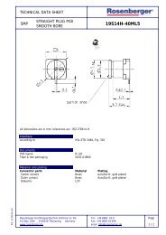
D4 S 20A- 40ML5-y<br />
Plating outer contact: AuroDur ® (L)<br />
Plating center contact: AuroDur ® (5)<br />
Au 0.15 μm non magnetic<br />
Die verwendeten Oberflächen bei Innen- und Außenleiter der <strong>Rosenberger</strong>-<br />
Steckverbinder sind in der Artikel- Bestellnummer definiert.<br />
Beispiel:<br />
D4 S 20A- 40ML5-y<br />
Oberfläche Außenleiter: AuroDur ® (L)<br />
Oberfläche Innenleiter: AuroDur ® (5)<br />
<strong>Rosenberger</strong> <strong>Hochfrequenztechnik</strong> GmbH & Co. KG, POB 1260, D- 84526 Tittmoning, Tel. +49- 86 84- 18- 0, Fax. +49- 86 84- 18- 499, www.rosenberger.de<br />
15<br />
3
16<br />
<strong>Rosenberger</strong> <strong>Hochfrequenztechnik</strong> GmbH & Co. KG, POB 1260, D- 84526 Tittmoning, Tel. +49- 86 84- 18- 0, Fax. +49- 86 84- 18- 499, www.rosenberger.de<br />
Technology<br />
Technology<br />
Technical Data Technische Daten<br />
Applicable standards Anwendbare Standards<br />
Interface according to <strong>Rosenberger</strong> Standard<br />
male D4S000- HSD<br />
female D4K000- HSD<br />
Interface gemäß<br />
Quality tested according to <strong>Rosenberger</strong> Norm RN 061- 01 Qualitätsprüfung gemäß<br />
Electrical data Elektrische Daten<br />
Impedance 100 Ω Wellenwiderstand<br />
Frequency range DC to 2 GHz Frequenzbereich<br />
Return loss ≤ - 20dB to 1 GHz<br />
≤ - 17dB to 2 GHz<br />
Rückflussdämpfung<br />
Insertion loss ≤ 0.1 dB to 2 GHz Dämpfung<br />
Skew (between signal contacts)<br />
Laufzeitunterschied<br />
Straight connectors<br />
≤ 5 psec. / m<br />
Steckverbinder gerade<br />
Right angle connectors<br />
≤ 25 psec. / m<br />
Winkel- Steckverbinder<br />
Nearend crosstalk ≤ 30 dB (1 GHz) Übersprechen nahes Ende<br />
Farend crosstalk ≤ 35 dB (1 GHz) Übersprechen fernes Ende<br />
Insulation resistance ≥ 1 x 10 3 MΩ Isolationswiderstand<br />
Signal contact resistance ≤ 10 mΩ Übergangswiderstand Signalleiter<br />
Outer contact resistance ≤ 7.5 mΩ Übergangswiderstand Außenleiter<br />
Test Voltage 250 Vrms Prüfspannung<br />
Working voltage 100 Vrms Betriebsspannung<br />
Contact current with Dacar 538 ≤ 1.5 A DC Kontakt- Strombelastbarkeit mit Dacar 538<br />
Differential shielding effectiveness ≥ 75 dB up to 1 GHz<br />
≥ 65 dB up to 2 GHz<br />
Differentielle Schirmdämpfung<br />
Mechanical data Mechanische Daten<br />
Mating cycles ≥ 25 Steckzyklen<br />
Engagement force ≤ 30 N Steckkraft<br />
Disengagement force ≥ 5 N Ziehkraft<br />
Retention force latch ≥ 110 N Haltekraft Wippe/Rastnase<br />
Retention force primary lock ≥ 80 N Haltekraft Primär- Sicherung<br />
Retention force secondary lock ≥ 60 N Haltekraft Sekundärverriegelung<br />
Polarization feature effectiveness ≥ 80 N Kodierungseffizienz<br />
Cable torsion ≥ 20 Ncm Kabeltorsion<br />
Environmental data Umweltdaten<br />
Temperature range - 40°C to +105°C Temperaturbereich<br />
Thermal shock DIN EN 60068- 2- 14 Temperaturwechsel<br />
Vibration DIN EN 60068- 2- 64 Vibration<br />
Mechanical shock DIN EN 60068- 2- 27 Mechanischer Schock<br />
Temperature and humidity USCar 2.4.- 5.6.2 Temperatur und Feuchte<br />
Dry heat DIN EN 60068- 2- 2 Trockene Wärme<br />
Max. soldering temperature DIN EN 60068- 2- 58, group 3 & 4 Maximale Löttemperatur
Technology<br />
Materials Materialien<br />
Outer contact CuZn, CuSn (Brass, Bronze), or equivalent Außenleiter<br />
Signal contacts CuZn, CuSn (Brass, Bronze), or equivalent Signalkontakte<br />
Dielectric PA, LCP, or equivalent Dielektrikum<br />
Gasket Silicone, Rubber, or equivalent Dichtung<br />
Crimping ferrule CuSn (Bronze), or equivalent Crimphülse<br />
Plastic housings and secondary lock PA, PBT, or equivalent Kunststoff- Gehäuse und Sekundärverriegelung<br />
Platings Oberflächen<br />
Outer contact AuroDur ® , Nickel Außenleiter<br />
Signal contacts AuroDur ®<br />
<strong>Rosenberger</strong> connectors fulfill in principle the indicated data of the Technical<br />
Data. Individual values of connectors may deviate depending upon<br />
application, design, type of cable, assembly method and execution. Specific<br />
data sheets for particular products can be provided on request from your<br />
<strong>Rosenberger</strong> sales partner.<br />
Signalkontakte<br />
<strong>Rosenberger</strong> Steckverbinder erfüllen grundsätzlich die in den Technischen<br />
Daten angegebenen Daten. Je nach Anwendung, Bauart, Kabeltyp, Montageart<br />
und - ausführung können einzelne Werte von Steckverbindern<br />
hiervon abweichen. Spezifische Datenblätter zu einzelnen Produkten<br />
erhalten Sie auf Anfrage von Ihrem <strong>Rosenberger</strong>- Ansprechpartner.<br />
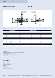
Interface Dimensions Anschlussmaße<br />
2.15 +0.1<br />
-0.2<br />
MALE<br />
Stecker<br />
REFERENCE PLANE<br />
Referenzebene<br />
0.75 +0.35<br />
-0.30<br />
5.3 +0.15<br />
-0.10<br />
REFERENCE PLANE<br />
Referenzebene<br />
FEMALE<br />
Kuppler<br />
<strong>Rosenberger</strong> <strong>Hochfrequenztechnik</strong> GmbH & Co. KG, POB 1260, D- 84526 Tittmoning, Tel. +49- 86 84- 18- 0, Fax. +49- 86 84- 18- 499, www.rosenberger.de<br />
2.2 +0.07<br />
-0.20<br />
0.3 +0.15<br />
-0.10<br />
1.35 +0.32<br />
-0.33<br />
17<br />
3
18<br />
Codings<br />
for PCB connectors and<br />
4- pole cable assemblies<br />
Coding<br />
A<br />
Jack Plug<br />
Colours of the plastic housings are in accordance with the listed RAL<br />
colours, minor colour differences during manufacturing are possible.<br />
B<br />
C<br />
D<br />
E<br />
F<br />
Z<br />
<strong>Rosenberger</strong> <strong>Hochfrequenztechnik</strong> GmbH & Co. KG, POB 1260, D- 84526 Tittmoning, Tel. +49- 86 84- 18- 0, Fax. +49- 86 84- 18- 499, www.rosenberger.de<br />
Codings<br />
Kodierungen<br />
für Leiterplatten- Steckverbinder und<br />
4- polige Kabelleitungen<br />
Color/<br />
RAL- Nr.<br />
Black/<br />
9005<br />
White/<br />
9001<br />
Blue/<br />
5005<br />
Bordeaux/<br />
4004<br />
Green/<br />
6002<br />
Brown/<br />
8011<br />
Waterblue/<br />
5021<br />
Die Farben der Kunststoffgehäuse entsprechen den genannten RAL- Farbbezeichnungen,<br />
geringfügige Farbabweichungen im Fertigungsprozess<br />
sind möglich.
PCB Connectors<br />
*PCB Connectors<br />
male - straight<br />
D4S10A- 400L5- Y<br />
solder version<br />
Remarks wave soldering,<br />
four signal pins<br />
Codings A, B, C, D, E, F, Z<br />
Packing Tape & reel<br />
Assembly D4 V 012<br />
Instruction<br />
Panel MB 214<br />
Piercing /<br />
PCB Layout<br />
male - right angle<br />
D4S20G- 400A5- Y<br />
solder version<br />
Remarks wave soldering,<br />
four signal pins<br />
Codings A, B, C, D, E, F, Z<br />
Packing Tape & reel<br />
Assembly D4 V 013<br />
Instruction<br />
Panel MB 261<br />
Piercing /<br />
PCB Layout<br />
male - straight<br />
D4S10A- 40ML5- Y<br />
SMD<br />
Remarks Pin- in- paste,<br />
four signal pins<br />
Codings A, B, C, D, E, F, Z<br />
Packing Tape & reel<br />
Assembly D4 V 016<br />
Instruction<br />
Panel MB 224<br />
Piercing /<br />
PCB Layout<br />
male - right angle<br />
D4S20D- 40ML5- Y<br />
SMD<br />
Remarks Pin- in- paste,<br />
four signal pins<br />
Codings A, B, C, D, E, F, Z<br />
Packing Tape & reel<br />
Assembly D4 V 010<br />
Instruction<br />
Panel MB 215<br />
Piercing /<br />
PCB Layout<br />
male - right angle<br />
D4S20F- 40MA5- Y<br />
SMD<br />
Remarks Pin- in- paste,<br />
four signal pins,<br />
EMI shielded<br />
Codings A, B, C, D, E, F, Z<br />
Packing Blister<br />
Assembly D4 V 011<br />
Instruction<br />
Panel MB 238<br />
Piercing /<br />
PCB Layout<br />
male - right angle<br />
D4S20C- 400A5- Y<br />
solder version<br />
Remarks wave soldering,<br />
four signal pins,<br />
EMI shielding ring preassembled<br />
Codings A, B, C, D, E, F, Z<br />
Packing Blister<br />
Assembly D4 V 011<br />
Instruction<br />
Panel MB 215<br />
Piercing /<br />
PCB Layout<br />
Ordering instructions:<br />
y: please fill- in requested coding<br />
Bestellhinweise:<br />
y: gewünschte Kodierung einfügen<br />
Example / Beispiel:<br />
D4S10A- 400 L5- Y<br />
Coding<br />
<strong>Rosenberger</strong> <strong>Hochfrequenztechnik</strong> GmbH & Co. KG, POB 1260, D- 84526 Tittmoning, Tel. +49- 86 84- 18- 0, Fax. +49- 86 84- 18- 499, www.rosenberger.de<br />
19<br />
3
20<br />
Ordering Instructions<br />
Please fill- in requested cable assembly length (in mm) and codings<br />
Example:<br />
LD 5- 204- xxxx- x- x<br />
LD 5- 204- 0900- A- D<br />
Coding side B<br />
Coding side A<br />
Cable length in mm<br />
*Cable Assemblies<br />
Cable Assemblies<br />
xOrdering Number Side A Side B<br />
xLD5- 101- xxxx- x- x Jack,<br />
straight<br />
xLD5- 102- xxxx- x- x Jack,<br />
straight<br />
xLD5- 103- xxxx- x- x Plug,<br />
straight<br />
xLD5- 104- xxxx- x- x Plug,<br />
straight<br />
xLD5- 201- xxxx- x- x Jack,<br />
straight<br />
xLD5- 203- xxxx- x- x Jack,<br />
straight<br />
xLD5- 204- xxxx- x- x Jack,<br />
straight<br />
xLD5- 205- xxxx- x- x Plug,<br />
straight<br />
xLD5- 207- xxxx- x- x Plug,<br />
straight<br />
Jack,<br />
straight<br />
Plug,<br />
straight<br />
Jack,<br />
straight<br />
Plug,<br />
straight<br />
Jack, 90°,<br />
cable down<br />
Jack, 90°,<br />
cable left<br />
Jack, 90°,<br />
cable right<br />
Jack, 90°,<br />
cable down<br />
Jack, 90°,<br />
cable left<br />
Bestellhinweise<br />
Cable Assemblies<br />
Bitte ergänzen Sie die gewünschte Kabellänge (in mm) sowie die<br />
benötigten Kodierungen für die Seiten A und B<br />
Beispiel:<br />
LD 5- 204- xxxx- x- x<br />
LD 5- 204- 0900- A- D<br />
Kodierung Seite B<br />
Kodierung Seite A<br />
Kabellänge in mm<br />
<strong>Rosenberger</strong> <strong>Hochfrequenztechnik</strong> GmbH & Co. KG, POB 1260, D- 84526 Tittmoning, Tel. +49- 86 84- 18- 0, Fax. +49- 86 84- 18- 499, www.rosenberger.de
Cable Assemblies<br />
Ordering Instructions<br />
Please fill- in requested cable assembly length (in mm) and codings<br />
Example:<br />
LD 5- 204- xxxx- x- x<br />
LD 5- 204- 0900- A- D<br />
Coding side B<br />
Coding side A<br />
Cable length in mm<br />
xOrdering Number Side A Side B<br />
xLD5- 208- xxxx- x- x Plug,<br />
straight<br />
xLD5- 209- xxxx- x- x Jack, 90°,<br />
cable down<br />
xLD5- 211- xxxx- x- x Jack, 90°,<br />
cable right<br />
xLD5- 212- xxxx- x- x Jack, 90°,<br />
cable left<br />
xLD5- 213- xxxx- x- x Jack, 90°,<br />
cable down<br />
xLD5- 215- xxxx- x- x Jack, 90°,<br />
cable right<br />
xLD5- 216- xxxx- x- x Jack, 90°,<br />
cable left<br />
xLD5- 217- xxxx- x- x Jack, 90°,<br />
cable down<br />
xLD5- 219- xxxx- x- x Jack, 90°,<br />
cable right<br />
Jack, 90°,<br />
cable right<br />
Jack,<br />
straight<br />
Jack,<br />
straight<br />
Jack,<br />
straight<br />
Plug,<br />
straight<br />
Plug,<br />
straight<br />
Plug,<br />
straight<br />
Jack, 90°,<br />
cable down<br />
Jack, 90°,<br />
cable down<br />
Bestellhinweise<br />
Bitte ergänzen Sie die gewünschte Kabellänge (in mm) sowie die<br />
benötigten Kodierungen für die Seiten A und B<br />
Beispiel:<br />
LD 5- 204- xxxx- x- x<br />
LD 5- 204- 0900- A- D<br />
Kodierung Seite B<br />
Kodierung Seite A<br />
Kabellänge in mm<br />
<strong>Rosenberger</strong> <strong>Hochfrequenztechnik</strong> GmbH & Co. KG, POB 1260, D- 84526 Tittmoning, Tel. +49- 86 84- 18- 0, Fax. +49- 86 84- 18- 499, www.rosenberger.de<br />
21<br />
3
22<br />
Ordering Instructions<br />
Please fill- in requested cable assembly length (in mm) and codings<br />
Example:<br />
LD 5- 204- xxxx- x- x<br />
LD 5- 204- 0900- A- D<br />
Coding side B<br />
Coding side A<br />
Cable length in mm<br />
xOrdering Number Side A Side B<br />
xLD5- 220- xxxx- x- x Jack, 90°,<br />
cable left<br />
xLD5- 225- xxxx- x- x Jack, 90°,<br />
cable down<br />
xLD5- 227- xxxx- x- x Jack, 90°,<br />
cable right<br />
xLD5- 228- xxxx- x- x Jack, 90°,<br />
cable left<br />
xLD5- 229- xxxx- x- x Jack, 90°,<br />
cable down<br />
xLD5- 231- xxxx- x- x Jack, 90°,<br />
cable right<br />
xLD5- 232- xxxx- x- x Jack, 90°,<br />
cable left<br />
Jack, 90°,<br />
cable down<br />
Jack, 90°,<br />
cable right<br />
Jack, 90°,<br />
cable right<br />
Jack, 90°,<br />
cable right<br />
Jack, 90°,<br />
cable left<br />
Jack, 90°,<br />
cable left<br />
Jack, 90°,<br />
cable left<br />
Bestellhinweise<br />
Cable Assemblies<br />
Bitte ergänzen Sie die gewünschte Kabellänge (in mm) sowie die<br />
benötigten Kodierungen für die Seiten A und B<br />
Beispiel:<br />
LD 5- 204- xxxx- x- x<br />
LD 5- 204- 0900- A- D<br />
Kodierung Seite B<br />
Kodierung Seite A<br />
Kabellänge in mm<br />
<strong>Rosenberger</strong> <strong>Hochfrequenztechnik</strong> GmbH & Co. KG, POB 1260, D- 84526 Tittmoning, Tel. +49- 86 84- 18- 0, Fax. +49- 86 84- 18- 499, www.rosenberger.de
Codings, Cable Up<br />
Codings, Cable Up<br />
Codings, Cable Up Kodierungen, Cable Up<br />
Coding<br />
Jack Plug<br />
Colours of the plastic housings are in accordance with the listed RAL<br />
colours, minor colour differences during manufacturing are possible.<br />
G<br />
H<br />
J<br />
K<br />
L<br />
M<br />
O<br />
Color/<br />
RAL- Nr.<br />
<strong>Rosenberger</strong> <strong>Hochfrequenztechnik</strong> GmbH & Co. KG, POB 1260, D- 84526 Tittmoning, Tel. +49- 86 84- 18- 0, Fax. +49- 86 84- 18- 499, www.rosenberger.de<br />
Grey/<br />
7031<br />
Violet/<br />
4003<br />
Beige/<br />
1001<br />
Curry/<br />
1027<br />
Yellow Green/<br />
6018<br />
Pastel Orange/<br />
2003<br />
Light Green/<br />
6027<br />
Die Farben der Kunststoffgehäuse entsprechen den genannten RAL- Farbbezeichnungen,<br />
geringfügige Farbabweichungen im Fertigungsprozess<br />
sind möglich.<br />
23<br />
3
24<br />
male - right angle<br />
*PCB Connectors, Cable Up * *<br />
D4S2UG- 400A5- Y<br />
solder version<br />
Remarks wave soldering,<br />
four signal pins<br />
Codings G, H, I, K, L, M, O<br />
Packing Tape & reel<br />
Assembly D4 V 013<br />
Instruction<br />
Panel MB 261<br />
Piercing /<br />
PCB Layout<br />
male - right angle<br />
D4S2UD- 40ML5- Y<br />
SMD<br />
Remarks Pin- in- paste,<br />
four signal pins<br />
Codings G, H, I, K, L, M, O<br />
Packing Tape & reel<br />
Assembly D4 V 010<br />
Instruction<br />
Panel MB 215<br />
Piercing /<br />
PCB Layout<br />
male - right angle<br />
D4S2UF- 40MA5- Y<br />
SMD<br />
Remarks Pin- in- paste,<br />
four signal pins,<br />
EMI shielded<br />
Codings G, H, I, K, L, M, O<br />
Packing Blister<br />
Assembly D4 V 011<br />
Instruction<br />
Panel MB 238<br />
Piercing /<br />
PCB Layout<br />
PCB Connectors, Cable Up<br />
Ordering instructions:<br />
y: please fill- in requested coding<br />
Bestellhinweise:<br />
y: gewünschte Kodierung einfügen<br />
Example / Beispiel:<br />
D4S2UG- 400 A5- Y<br />
Coding<br />
<strong>Rosenberger</strong> <strong>Hochfrequenztechnik</strong> GmbH & Co. KG, POB 1260, D- 84526 Tittmoning, Tel. +49- 86 84- 18- 0, Fax. +49- 86 84- 18- 499, www.rosenberger.de
Cable Assemblies, Cable Up<br />
Ordering Instructions<br />
Please fill- in requested cable assembly length (in mm) and codings<br />
Coding:<br />
Please use codings listed on page 23 for cable up- side, otherwise codings<br />
listed on page 18<br />
Example:<br />
LD 5- 202- xxxx- x- x<br />
LD 5- 202- 0900- A- G<br />
Coding side B<br />
Coding side A<br />
Cable length in mm<br />
Cable Assemblies, Cable Up<br />
Cable Assemblies<br />
xOrdering Number Side A Side B Remarks<br />
xLD5- 202- xxxx- x- x Jack,<br />
straight<br />
xLD5- 206- xxxx- x- x Plug,<br />
straight<br />
xLD5- 210- xxxx- x- x Jack, 90°,<br />
cable up<br />
xLD5- 214- xxxx- x- x Jack, 90°,<br />
cable up<br />
xLD5- 218- xxxx- x- x Jack, 90°,<br />
cable up<br />
xLD5- 221- xxxx- x- x Jack, 90°,<br />
cable down<br />
xLD5- 222- xxxx- x- x Jack, 90°,<br />
cable up<br />
Jack, 90°,<br />
cable up<br />
Jack, 90°,<br />
cable up<br />
Jack,<br />
straight<br />
Plug,<br />
straight<br />
Jack, 90°,<br />
cable down<br />
Jack, 90°,<br />
cable up<br />
Jack, 90°,<br />
cable up<br />
Side B: only mateable<br />
with PCB plugs, cable up<br />
Side B: only mateable<br />
with PCB plugs, cable up<br />
Side A: only mateable<br />
with PCB plugs, cable up<br />
Side A: only mateable<br />
with PCB plugs, cable up<br />
Side A: only mateable<br />
with PCB plugs, cable up<br />
Side B: only mateable<br />
with PCB plugs, cable up<br />
Side A and B: only mateable<br />
with PCB plugs, cable up<br />
Bestellhinweise<br />
Bitte ergänzen Sie die gewünschte Kabellänge (in mm) sowie die<br />
benötigten Kodierungen für die Seiten A und B<br />
Kodierung:<br />
Bitte verwenden Sie für die Cable- up- Seite die Kodierungen auf Seite 23,<br />
ansonsten die Kodierungen auf Seite 18<br />
Beispiel:<br />
LD 5- 202- xxxx- x- x<br />
LD 5- 202- 0900- A- G<br />
Kodierung Seite B<br />
Kodierung Seite A<br />
Kabellänge in mm<br />
<strong>Rosenberger</strong> <strong>Hochfrequenztechnik</strong> GmbH & Co. KG, POB 1260, D- 84526 Tittmoning, Tel. +49- 86 84- 18- 0, Fax. +49- 86 84- 18- 499, www.rosenberger.de<br />
25<br />
3
26<br />
Ordering Instructions<br />
Please fill- in requested cable assembly length (in mm) and codings<br />
Coding:<br />
Please use codings listed on page 23 for cable up- side, otherwise codings<br />
listed on page 18<br />
Example:<br />
LD 5- 202- xxxx- x- x<br />
LD 5- 202- 0900- A- G<br />
Coding side B<br />
Coding side A<br />
Cable length in mm<br />
xOrdering Number Side A Side B Remarks<br />
xLD5- 223- xxxx- x- x Jack, 90°,<br />
cable right<br />
xLD5- 224- xxxx- x- x Jack, 90°,<br />
cable left<br />
xLD5- 226- xxxx- x- x Jack, 90°,<br />
cable up<br />
xLD5- 230- xxxx- x- x Jack, 90°,<br />
cable up<br />
Jack, 90°,<br />
cable up<br />
Jack, 90°,<br />
cable up<br />
Jack, 90°,<br />
cable right<br />
Jack, 90°,<br />
cable left<br />
Side B: only mateable<br />
with PCB plugs, cable up<br />
Side B: only mateable<br />
with PCB plugs, cable up<br />
Side A: only mateable<br />
with PCB plugs, cable up<br />
Side A: only mateable<br />
with PCB plugs, cable up<br />
Bestellhinweise<br />
Cable Assemblies, Cable Up<br />
Bitte ergänzen Sie die gewünschte Kabellänge (in mm) sowie die<br />
benötigten Kodierungen für die Seiten A und B<br />
Kodierung:<br />
Bitte verwenden Sie für die Cable- up- Seite die Kodierungen auf Seite 23,<br />
ansonsten die Kodierungen auf Seite 18<br />
Beispiel:<br />
LD 5- 202- xxxx- x- x<br />
LD 5- 202- 0900- A- G<br />
Kodierung Seite B<br />
Kodierung Seite A<br />
Kabellänge in mm<br />
<strong>Rosenberger</strong> <strong>Hochfrequenztechnik</strong> GmbH & Co. KG, POB 1260, D- 84526 Tittmoning, Tel. +49- 86 84- 18- 0, Fax. +49- 86 84- 18- 499, www.rosenberger.de
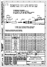
Cable Connectors, Dimensions<br />
*3MP Cable change Connectors, Footprint Dimensions<br />
Plug, straight<br />
13.95<br />
Jack 90°, cable down<br />
11.65<br />
Jack 90°, cable left<br />
17.75<br />
8.15<br />
26<br />
17.75<br />
11.65<br />
8.15<br />
32.35<br />
27.5<br />
30.5<br />
12<br />
ø5.9<br />
Jack, straight<br />
<strong>Rosenberger</strong> <strong>Hochfrequenztechnik</strong> GmbH & Co. KG, POB 1260, D- 84526 Tittmoning, Tel. +49- 86 84- 18- 0, Fax. +49- 86 84- 18- 499, www.rosenberger.de<br />
13.75<br />
Jack 90°, cable up<br />
11.65<br />
Jack 90°, cable right<br />
12<br />
8.15<br />
17.75<br />
26<br />
29.9<br />
27.5<br />
11.65<br />
8.15<br />
30.5<br />
17.75<br />
ø5.9<br />
27<br />
3
28<br />
Panel Piercings / PCB Layouts Panel Piercings - PCB Layouts<br />
4Panel Piercings / PCB Layouts<br />
On request, <strong>Rosenberger</strong> will provide PCB layout recommendations. For<br />
your specific board stack- up, please request for optimized "footprint" for<br />
your application.<br />
Auf Anfrage stellt <strong>Rosenberger</strong> Leiterplatten- Layouts (Empfehlungen) für<br />
Ihren spezifischen Lagenaufbau zur Verfügung. Bezüglich des für Ihre<br />
Anwendung optimalen "Footprint", wenden Sie sich bitte an Ihren <strong>Rosenberger</strong>-<br />
Ansprechpartner.<br />
MB 215<br />
�" #<br />
% �%<br />
MB 238<br />
�" #<br />
% �%<br />
" �& #<br />
" �& #<br />
�& #<br />
�& #<br />
% �#<br />
� �$ #<br />
#<br />
' �#<br />
% �#<br />
� �$ #<br />
#<br />
�#<br />
�<br />
� �'<br />
�<br />
� �'<br />
� �"<br />
� �"<br />
�&<br />
�$<br />
MB 214<br />
MB 224<br />
MB 261<br />
<strong>Rosenberger</strong> <strong>Hochfrequenztechnik</strong> GmbH & Co. KG, POB 1260, D- 84526 Tittmoning, Tel. +49- 86 84- 18- 0, Fax. +49- 86 84- 18- 499, www.rosenberger.de<br />
�% #<br />
'<br />
# �#<br />
� �!<br />
I � �@ A H = HA =<br />
� �<br />
� �<br />
� �<br />
! �#<br />
�<br />
� �<br />
� � � �<br />
�#<br />
� �<br />
& �!<br />
$<br />
$<br />
� �<br />
I � �@ A H = HA =<br />
'<br />
� �%<br />
� �$<br />
� �!<br />
� �&<br />
�<br />
� �%<br />
� �!<br />
� �'<br />
� �<br />
� �<br />
� �<br />
� �<br />
� �<br />
� �<br />
� �%<br />
� �<br />
A @ C A � B 2 + *<br />
� �<br />
� �"
PCB Connectors<br />
D4S10A- 400L5- Y .................................19<br />
D4S10A- 40ML5- Y ...............................19<br />
D4S20C- 400A5- Y ................................19<br />
D4S20G- 400A5- Y ................................19<br />
D4S20D- 40ML5- Y ...............................19<br />
D4S20F- 40MA5- Y ...............................19<br />
PCB Connectors, Cable Up<br />
D4S2UG-400A5-Y ...............................24<br />
D4S2UD- 40ML5- Y ...............................24<br />
D4S2UF-40MA5-Y ...............................24<br />
Cable Assemblies<br />
LD5- 101- xxxx- x- x ...............................20<br />
LD5- 102- xxxx- x- x ...............................20<br />
LD5- 103- xxxx- x- x ...............................20<br />
LD5- 104- xxxx- x- x ...............................20<br />
LD5- 201- xxxx- x- x ...............................20<br />
LD5- 203- xxxx- x- x ...............................20<br />
LD5- 204- xxxx- x- x ...............................20<br />
LD5- 205- xxxx- x- x ...............................20<br />
LD5- 207- xxxx- x- x ...............................20<br />
LD5- 208- xxxx- x- x ...............................21<br />
LD5- 209- xxxx- x- x ...............................21<br />
LD5- 211- xxxx- x- x ...............................21<br />
LD5- 212- xxxx- x- x ...............................21<br />
LD5- 213- xxxx- x- x ...............................21<br />
LD5- 215- xxxx- x- x ...............................21<br />
LD5- 216- xxxx- x- x ...............................21<br />
LD5- 217- xxxx- x- x ...............................21<br />
LD5- 219- xxxx- x- x ...............................21<br />
LD5- 220- xxxx- x- x ...............................22<br />
LD5- 225- xxxx- x- x ...............................22<br />
LD5- 227- xxxx- x- x ...............................22<br />
LD5- 228- xxxx- x- x ...............................22<br />
LD5- 229- xxxx- x- x ...............................22<br />
LD5- 231- xxxx- x- x ...............................22<br />
LD5- 232- xxxx- x- x ...............................22<br />
Cable Assemblies, Cable Up<br />
LD5- 202- xxxx- x- x ...............................25<br />
LD5- 206- xxxx- x- x ...............................25<br />
LD5- 210- xxxx- x- x ...............................25<br />
LD5- 214- xxxx- x- x ...............................25<br />
LD5- 218- xxxx- x- x ...............................25<br />
LD5- 221- xxxx- x- x ...............................25<br />
LD5- 222- xxxx- x- x ...............................25<br />
LD5- 223- xxxx- x- x ...............................26<br />
LD5- 224- xxxx- x- x ...............................26<br />
LD5- 226- xxxx- x- x ...............................26<br />
LD5- 230- xxxx- x- x ...............................26<br />
<strong>Rosenberger</strong> <strong>Hochfrequenztechnik</strong> GmbH & Co. KG, POB 1260, D- 84526 Tittmoning, Tel. +49- 86 84- 18- 0, Fax. +49- 86 84- 18- 499, www.rosenberger.de<br />
Index<br />
29
���������������������������<br />
�<br />
������������<br />
����������������������������������<br />
������������<br />
������������������<br />
����� ��������������������� �� �������� �������������������<br />
����� ����������������������� �� ����� �������������������<br />
Germany<br />
��������������������������<br />
������������������<br />
�����������<br />
���������������������<br />
����� �����������������������<br />
����������������������������<br />
���������������������������������<br />
�������������<br />
�����������<br />
���������������������<br />
�����������������������<br />
����������������������<br />
����������������������������<br />
Europe<br />
������<br />
������������������<br />
��������<br />
��������������������������<br />
�������������������<br />
����� ����������������������<br />
���������������������������<br />
�����������������������������������������<br />
�����<br />
�������������<br />
���������������������������������<br />
�������������������<br />
����� �����������������������<br />
�����������������������������<br />
�����������������������������������������<br />
������<br />
����������������������<br />
���������������<br />
��������������<br />
���������������������������<br />
����� ���������������������<br />
��������������������������<br />
���������������������������<br />
��������������<br />
���������������������������<br />
����������������<br />
�������������������������<br />
��������������������<br />
����� ��������������������������<br />
�������������������������������<br />
������������������������<br />
Asia<br />
����������������������<br />
�������������<br />
���������������������������������<br />
����������������������������<br />
�������������������������������<br />
��������������<br />
��������<br />
����� �����������������������<br />
����������������������������<br />
�������������������������������<br />
�����<br />
������������������������������������<br />
�����������<br />
����������������������<br />
��������������������<br />
��������������<br />
����� ����������������������<br />
���������������������������<br />
���������������������������<br />
�����<br />
���������������������<br />
�������������������<br />
����������������������<br />
����������������<br />
����� ����������������������<br />
���������������������������<br />
�����������������������<br />
�����<br />
������������������������<br />
����������������������������<br />
��������<br />
�����������<br />
���������������������<br />
����� ����������������������<br />
���� ����������������������<br />
����������������������������<br />
South America<br />
������<br />
�������������������������<br />
�����������������<br />
�����������������<br />
���������������������������<br />
�������������<br />
����� ����������������������<br />
���������������������������<br />
�������������������������<br />
��������������������<br />
����������������������������<br />
��������������<br />
�����������������<br />
����� ���������������������<br />
��������������������������<br />
����������������������������������<br />
North America<br />
�����������<br />
����������������������������������<br />
���������������������������<br />
��������������<br />
����������������������������<br />
����� ��������������������<br />
�������������������������<br />
������������������������������<br />
��������������� �� ������������������������������������������������������������������������������������������������<br />
���������������������������������������������������������������������������������������������������������������������������������������������������������������������������������������������<br />
��������������������������������������������
How to reach <strong>Rosenberger</strong><br />
Address for visitors:<br />
Hauptstrasse 1<br />
D-83413 Fridolfing<br />
<strong>Rosenberger</strong><br />
<strong>Hochfrequenztechnik</strong> GmbH & Co. KG<br />
P.O.Box 1260<br />
D-84526 Tittmoning<br />
Tel: + 49 - 86 84 -18-0<br />
Fax: + 49 - 86 84 -18-499<br />
E-Mail: info@rosenberger.de<br />
Web: www.rosenberger.com<br />
Certified by ISO/TS 16949 . ISO 9001 . ISO 14001<br />
Ordering No.<br />
Info 205 HSDCat/2000/04-2010<br />
pA 170061<br />
© 04.2010 <strong>Rosenberger</strong><br />
Production Thewald Kommunikation