Nutensteine, Schrauben und Zubehör Slot stones, screws ... - Aratron
Nutensteine, Schrauben und Zubehör Slot stones, screws ... - Aratron
Nutensteine, Schrauben und Zubehör Slot stones, screws ... - Aratron

Erfolgreiche ePaper selbst erstellen
Machen Sie aus Ihren PDF Publikationen ein blätterbares Flipbook mit unserer einzigartigen Google optimierten e-Paper Software.
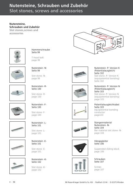
<strong>Nutensteine</strong>, <strong>Schrauben</strong> <strong>und</strong> <strong>Zubehör</strong><br />
<strong>Slot</strong> <strong>stones</strong>, <strong>screws</strong> and accessories<br />
<strong>Nutensteine</strong>,<br />
<strong>Schrauben</strong> <strong>und</strong> <strong>Zubehör</strong><br />
<strong>Slot</strong> <strong>stones</strong>,<strong>screws</strong> and<br />
accessories<br />
Hammerschraube<br />
Seite 99<br />
T-head bolt<br />
page 99<br />
Nutenstein -N-<br />
Seite 99<br />
<strong>Slot</strong> stone -Npage<br />
99<br />
Nutenstein -R-<br />
Seite 100<br />
<strong>Slot</strong> stone -Rpage<br />
100<br />
Nutenstein -F-<br />
Seite 100<br />
<strong>Slot</strong> stone -Fpage<br />
100<br />
Nutenstein -L-<br />
Seite 101<br />
<strong>Slot</strong> stone -Lpage<br />
101<br />
Nutenstein -E-<br />
Seite 101<br />
<strong>Slot</strong> stone -Epage<br />
101<br />
Nutenstein -K-<br />
Seite 102<br />
<strong>Slot</strong> stone -Kpage<br />
102<br />
Nutenstein -P- Version K<br />
(Potentialausgleich)<br />
Seite 102<br />
<strong>Slot</strong> stone -P- Version K<br />
(equipotential bonding)<br />
Seite 102<br />
Nutenstein -P- Version N<br />
(Potentialausgleich)<br />
Seite 103<br />
<strong>Slot</strong> stone -P- Version N<br />
(equipotential bonding)<br />
page 103<br />
Potentialausgleichkabel<br />
Seite 103<br />
equipotential bonding<br />
conductor<br />
page103<br />
Stangenmaterial<br />
Nutenstein -N-<br />
Seite 104<br />
Bar material slot stone -Npage<br />
104<br />
Hängegleiter<br />
Seite 106<br />
Suspended sliding block<br />
page 106<br />
<strong>Schrauben</strong><br />
Seite 107<br />
Screws<br />
page 107<br />
II - 98 RK Rose+Krieger GmbH & Co. KG � Postfach 15 64 � D-32375 Minden
Hammerschraube<br />
T-head bolt<br />
Zur Befestigung von Profilverbindern<br />
<strong>und</strong> Knotenwinkeln. Die<br />
Hammerschraube kann an beliebiger<br />
Stelle in die Profilnut eingesetzt<br />
werden. Beim Festschrauben<br />
dreht sich die Hammerschraube in<br />
die endgültige Spannposition.<br />
Material: Stahl galvanisiert.<br />
Lieferumfang: Komplett mit Mutter<br />
<strong>und</strong> Unterlegscheibe.<br />
Nutenstein -N- (normal)<br />
<strong>Slot</strong> stone -N- (normal)<br />
Zur Befestigung von Profilverbindern,<br />
Knotenwinkeln <strong>und</strong> Anschlussplatten.<br />
Dieser Nutenstein<br />
sollte vor der Montage eingeschoben<br />
werden.<br />
Ausnahme: Vergleiche Montagetips<br />
I - Seite 21.<br />
Material: Stahl galvanisiert.<br />
D-BL 08/2005<br />
Used for fastening mitre joints and<br />
angle brackets. The T-head bolt<br />
can be applied in the profile slot at<br />
any desired position. When screwing<br />
it the T-head bolt rotates in<br />
the final tensioning position.<br />
Material: galvanised steel<br />
Delivery set: complete with nut<br />
and disc.<br />
Code No. Type Passend für: fits for: A<br />
[mm]<br />
M F [N]<br />
4.016201 M8x25 40er Nutgeometrie slot geometry 40 25 M8 6000<br />
Used for fastening mitre joints, angle<br />
brackets and connecting plates.<br />
This slot stone should be<br />
inserted before assembling.<br />
Exception: cp. assembly tips in chp.<br />
I - page 21.<br />
Material: galvanised steel<br />
RK ROSE+ KRIEGER<br />
Code No. Type Nutgeometrie <strong>Slot</strong> geometry A B C D E<br />
[mm]<br />
M F [N]<br />
4.006201 M5 30 5 10 13 13 3 M5 4000<br />
4.006203 M6 30 5 10 13 13 3 M6 4000<br />
4.006202 M8 30 5 10 13 13 3 M8 4000<br />
4.026207 M5 40 8 10 13 15 4 M5 4000<br />
4.026203 M6 40 8 10 13 15 4 M6 9000<br />
4.026206 M8 40 8 10 13 15 4 M8 9000<br />
4.026208 M8 40, mit Schraube M8x16 with screw M8x16 8 10 13 15 4 M8 9000<br />
4.026202 M8 40, mit Schraube M8x18 with screw M8x18 8 10 13 15 4 M8 9000<br />
II - 99<br />
I<br />
II<br />
III<br />
IV<br />
V<br />
VI
<strong>Nutensteine</strong>, <strong>Schrauben</strong> <strong>und</strong> <strong>Zubehör</strong><br />
<strong>Slot</strong> <strong>stones</strong>, <strong>screws</strong> and accessories<br />
Nutenstein -R- (Rhombus)<br />
<strong>Slot</strong> stone -R- (rhombic)<br />
Rhombussteine können an beliebiger<br />
Stelle in die Profilnut eingelegt<br />
werden. Beim Festschrauben dreht<br />
sich der Nutenstein in die endgültige<br />
Spannposition.<br />
Material: Stahl galvanisiert.<br />
Code No. Type Passend für: fits for: A B C M F [N]<br />
4.006222 M5 30er Nutgeometrie slot geometry 30 13 5 10 M5 4000<br />
4.006221 M6 30er Nutgeometrie slot geometry 30 13 5 10 M6 4000<br />
4.006223 M8 30er Nutgeometrie slot geometry 30 13 5 10 M8 4000<br />
4.026221 M6 40er Nutgeometrie slot geometry 40 15 9 10 M6 8000<br />
4.026222 M8 40er Nutgeometrie slot geometry 40 15 9 10 M8 8000<br />
Nutenstein -F- (mit Feder)<br />
<strong>Slot</strong> stone -F- (with spring clip)<br />
Dieser Federnutenstein wird verwendet<br />
bei Spannbügel- / Flanschleistenverbindungen.<br />
Dieser Federnutenstein lässt sich in<br />
die Profilnut einsetzen / einschwenken<br />
<strong>und</strong> an beliebiger Position<br />
fixieren.<br />
Die Feder gewährleistet einwandfreien<br />
Halt – auch in senkrechten<br />
Einbaulagen.<br />
Material: Stahl galvanisiert<br />
Rhombic slot <strong>stones</strong> can be placed<br />
anywhere in the profile slot. When<br />
tightening, the slot stone rotate in<br />
the final tensioning position.<br />
Material: galvanised steel<br />
This slot stone with spring clip is<br />
used for hidden bracket / flange<br />
bracket connections.<br />
The slot stone with spring clip can<br />
be inserted/ introduced in the profile<br />
slot and fixed at any desired<br />
position.<br />
The spring clip guarantees a perfect<br />
support – even in vertical position.<br />
Material: galvanised steel<br />
Federbügel<br />
Spring clip<br />
Code No. Type Passend für: fits for: A B C M F [N]<br />
4.006710 M3 alle all 10 12 4 M3 3000<br />
4.006716 M4 alle all 10 12 4 M4 3500<br />
4.006711 M5 alle all 10 12 4 M5 4000<br />
4.006712 M6 alle all 10 12 4 M6 4500<br />
4.006715 M4 40er Nutgeometrie slot geometry 40 10 14 4 M4 3500<br />
4.006713 M5 40er Nutgeometrie slot geometry 40 10 14 4 M5 4000<br />
4.006714 M6 40er Nutgeometrie slot geometry 40 10 14 4 M6 4500<br />
II - 100 RK Rose+Krieger GmbH � Postfach 15 64 � D-32375 Minden<br />
[mm]<br />
[mm]
Nutenstein -L- (lang)<br />
<strong>Slot</strong> stone -L- (long)<br />
Zur Befestigung von Spannbügeln.<br />
Komplett mit <strong>Schrauben</strong><br />
DIN 7984.<br />
Der Nutenstein lässt sich in die Profilnut<br />
einschwenken / einsetzen<br />
<strong>und</strong> mit einer Feder an beliebiger<br />
Position fixieren.<br />
Material: Stahl galvanisiert.<br />
Code No. Type Passend für: fits for: A B C D M F [N]<br />
4.006204 M5x8 30er Nutgeometrie slot geometry 30 29 12 21,5 4 M5 7000<br />
4.006205 M5x10 30er Nutgeometrie slot geometry 30 29 12 21,5 4 M5 7000<br />
4.006206 M5x12 30er Nutgeometrie slot geometry 30 29 12 21,5 4 M5 7000<br />
4.016204 M6x10 40er Nutgeometrie slot geometry 40 38 14 28 4 M6 10.000<br />
4.016205 M6x16 40er Nutgeometrie slot geometry 40 38 14 28 4 M6 10.000<br />
4.026204 M6x12 S/F-Profile 60 58 14 46 4 M6 12.000<br />
4.026205 M6x20 S/F-Profile 60 58 14 46 4 M6 12.000<br />
4.046204 M6x10 S/F-Profile 80 78 14 68 4 M6 12.000<br />
Nutenstein -E- (einschiebbar)<br />
<strong>Slot</strong> stone -E- (slide-in)<br />
Die Funktionsweise entspricht denen<br />
der <strong>Nutensteine</strong> -F- <strong>und</strong> -L-.<br />
Die größeren Auflageflächen ermöglichen<br />
jedoch eine höhere<br />
Belastbarkeit des Nutensteins.<br />
Der Nutenstein wird vor der Montage<br />
seitlich in die Profilnut eingeschoben<br />
<strong>und</strong> kann mit einer Feder<br />
an beliebiger Position fixiert werden.<br />
Material: Stahl galvanisiert.<br />
D-BL 10/2003<br />
Used for the fixation of hidden<br />
brackets. Complete with <strong>screws</strong><br />
DIN 7984.<br />
The slot stone can be swung / introduced<br />
in the profile slot and fixed<br />
at any desired position through a<br />
spring clip.<br />
Material: galvanised steel<br />
Its operating mode corresponds to<br />
that of slot <strong>stones</strong> -F- and -L-.<br />
The larger bearing surface,<br />
though, increases the slot stone<br />
load capacity.<br />
The slot stone is slid in the profile<br />
slot laterally and can be fixed at<br />
any desired position through a<br />
spring clip.<br />
Material: galvanised steel<br />
Code No. Type Passend für: fits for: A B C D<br />
[mm]<br />
M F [N]<br />
4.006208 M5 40er Nutgeometrie <strong>Slot</strong> geometry 40 10 16,5 – 4 M5 7.000<br />
4.006209 M6 40er Nutgeometrie <strong>Slot</strong> geometry 40 10 16,5 – 4 M6 7.400<br />
4.006210 M6 40er Nutgeometrie <strong>Slot</strong> geometry 40 38 16,5 28 4 M6 11.000<br />
4.006236 M6 40er Nutgeometrie <strong>Slot</strong> geometry 40 58 16,5 46 4 M6 –<br />
4.006237 M6 40er Nutgeometrie <strong>Slot</strong> geometry 40 78 16,5 68 4 M6 –<br />
[mm]<br />
II - 101<br />
I<br />
II<br />
III<br />
IV<br />
V<br />
VI
<strong>Nutensteine</strong>, <strong>Schrauben</strong> <strong>und</strong> <strong>Zubehör</strong><br />
<strong>Slot</strong> <strong>stones</strong>, <strong>screws</strong> and accessories<br />
Nutenstein -K- (kurz)<br />
<strong>Slot</strong> stone -K- (short)<br />
Der Nutenstein lässt sich in die Profilnut<br />
einschwenken / einsetzen<br />
<strong>und</strong> mit einer Feder an beliebiger<br />
Position fixieren.<br />
Material: Stahl galvanisiert<br />
Code No. Type Passend für: fits for: A B C D<br />
[mm]<br />
M F [N]<br />
4.006211 M5 alle (außer S-60, s.S.8) all (except S-60, s.p.8) 21 12 4 7 M5 5000<br />
4.006212 M6 alle (außer S-60, s.S.8) all (except S-60, s.p.8) 21 12 4 7 M6 5000<br />
4.006213 M8 alle (außer S-60, s.S.8) all (except S-60, s.p.8) 21 12 4 7 M8 5000<br />
4.016212 M6 40er Nutgeometrie slot geometry 40 21 14 4 7 M6 5000<br />
4.016213 M8 40er Nutgeometrie slot geometry 40 21 14 4 7 M8 8000<br />
Nutenstein -P- Version K (als Potentialausgleich)<br />
<strong>Slot</strong> stone -P- version K (for equipotential bonding)<br />
Die untenstehenden <strong>Nutensteine</strong><br />
bieten die Möglichkeit, in Verbindung<br />
eines Spannbügel- bzw.<br />
Flanschleistensatzes, einen Potentialausgleich<br />
zwischen zwei Profilen<br />
herzustellen.<br />
Ein Nutenstein wird beim Verbindungssatz<br />
durch den Nutenstein<br />
-K- ausgetauscht. Der Gewindestift<br />
beschädigt die Eloxalschicht,<br />
ein Potentialausgleich wird hergestellt.<br />
The slot stone can be swung / introduced<br />
in the profile slot and fixed<br />
at any desired position through a<br />
spring clip.<br />
Material: galvanised steel<br />
When inserted in a hidden bracket<br />
or a flange bracket set, the below-mentioned<br />
slot <strong>stones</strong> make it<br />
possible to create an equipotential<br />
bonding between two profiles.<br />
A slot stone is replaced in the connection<br />
set by a slot stone -K-. The<br />
threaded pin damages the anodic<br />
coating thus generating an equipotential<br />
bonding.<br />
DIN 913<br />
austauschen<br />
replace<br />
Code No. Type Passend für: fits for: A B C D<br />
[mm]<br />
M F [N]<br />
4.006214 M5 alle (außer S-60, s.S.8) all (except S-60, s.p.8) 20 12 4 7 M5 5000<br />
4.006216 M6 alle (außer S-60, s.S.8) all (except S-60, s.p.8) 20 12 4 7 M6 5000<br />
4.006215 M6 40er Nutgeometrie slot geometry 40 20 14 4 7 M6 5000<br />
II - 102 RK Rose+Krieger GmbH & Co. KG � Postfach 15 64 � D-32375 Minden
Nutenstein -P- Version N (als Potentialausgleich)<br />
<strong>Slot</strong> stone -P- version N (as equipotential bonding)<br />
Bewirkt den Potentialausgleich<br />
zwischen zwei Profilen durch Zerstörung<br />
der Eloxalschicht (z. B. für<br />
Erdungsanschlüsse). Der Nutenstein<br />
kann in einen Montagesatz<br />
einfließen oder durch Brückenstücke<br />
miteinander verb<strong>und</strong>en<br />
werden.<br />
Material: Stahl galvanisiert.<br />
Dieser Nutenstein sollte vor der<br />
Montage eingeschoben werden.<br />
Ausnahme: vergleiche Montagetips<br />
I - Seite 21.<br />
Code No. Type Passend für: fits for: A B C D E<br />
[mm]<br />
M<br />
4.026212 M6 40er Nutgeometrie slot geometry 40 8 10 15 15 4 M6<br />
4.026213 M8 40er Nutgeometrie <strong>Slot</strong> geometry 40 8 10 15 15 4 M8<br />
Potentialausgleichkabel<br />
Equipotential bonding<br />
Potentialausgleichkabel 6mm² mit<br />
Kabelschuh,<br />
Länge 120 mm<br />
Befestigungssatz galvanisch verzinkt<br />
Equipotential bonding 6mm² with<br />
cable lug,<br />
length 120 mm<br />
zinc- plated fixation kit<br />
D-BL 10/2003<br />
It produces the equipotential bonding<br />
between two profiles by destroying<br />
their anodic coating. The<br />
slot stone can be used as single part<br />
or connected to another one<br />
through a bonding cable.<br />
Material: galvanised steel<br />
This slot stone should be slid into<br />
the slot before the assembly.<br />
Exception: cp. assembly instructions<br />
in chp. I - page 21.<br />
Potentialausgleich<br />
Equipotential bonding<br />
Befestigungssatz:<br />
Nutenstein -P-<br />
Zyl.-Schraube M6x10<br />
Scheiben<br />
Fixation kit:<br />
slot stone -Pcylinder<br />
head screw M6x10<br />
discs<br />
Code No. Type Nutgeometrie <strong>Slot</strong> geometry<br />
4.012590 Potentialausgleich (Kabel) equipotential bonding (cable) 40<br />
4.012591 Befestigungssatz komplett complete fixation set 40<br />
[mm]<br />
II - 103<br />
I<br />
II<br />
III<br />
IV<br />
V<br />
VI
<strong>Nutensteine</strong>, <strong>Schrauben</strong> <strong>und</strong> <strong>Zubehör</strong><br />
<strong>Slot</strong> <strong>stones</strong>, <strong>screws</strong> and accessories<br />
Stangenmaterial Nutenstein -N-<br />
Bar material slot stone -N-<br />
Das Stangenmaterial ermöglicht<br />
eine anwendungsspezifische Ablängung<br />
<strong>und</strong> Positionierung von<br />
Gewinden.<br />
Bearbeitung nach K<strong>und</strong>envorgabe<br />
auf Anfrage.<br />
Material: Stahl<br />
Gr<strong>und</strong>profil für Nutenstein -N-<br />
The bar material allows for cut to<br />
length and custom-designed positioning<br />
of threads.<br />
Machining upon request according<br />
to customer needs.<br />
Material: steel<br />
basic profile for slot stone -N-<br />
Code No. Nutgeometrie <strong>Slot</strong> geometry A B C D E<br />
4.006200 3010 30 5 10 3010 13 3<br />
4.026200 3010 40 8 10 3010 15 4<br />
II - 104 RK Rose+Krieger GmbH & Co. KG � Postfach 15 64 � D-32375 Minden
Verwendung der <strong>Nutensteine</strong><br />
(Federnutenstein -F-/Nutenstein -K-,-E- <strong>und</strong> -L-)<br />
usage of slot <strong>stones</strong><br />
(slot stone with spring clip -F-/slot <strong>stones</strong> -K- and -L-)<br />
Code No. s. S. see p.<br />
in Nut einschieben<br />
insert into the slot<br />
Nutenstein -F- <strong>Slot</strong> stone -F-<br />
D-BL 10/2003<br />
30er Nutgeometrie <strong>Slot</strong> geometry 30 40er Nutgeometrie <strong>Slot</strong> geometry 40<br />
in Nut einschwenken<br />
swivel into the slot<br />
in Nut einschieben<br />
insert into the slot<br />
in Nut einschwenken<br />
swivel into the slot<br />
4.006710 100 x x x x<br />
4.006716 100 x x x x<br />
4.006711 100 x x x x<br />
4.006712 100 x x x x<br />
4.006715 100 x x x<br />
4.006713 100 x x x<br />
4.006714 100 x x x<br />
4.026714 100 x x x<br />
Nutenstein -L- <strong>Slot</strong> stone -L-<br />
4.006204 101 x x x x<br />
4.006205 101 x x x x<br />
4.006206 101 x x x x<br />
4.016204 101 x x x<br />
4.016205 101 x x x<br />
4.026204 101 x x x x<br />
4.026205 101 x x x x<br />
4.046204 101 x x x x<br />
Nutenstein -E- <strong>Slot</strong> stone -E-<br />
4.006208 101 x<br />
4.006209 101 x<br />
4.006210 101 x<br />
4.006236 101 x<br />
4.006237 101 x<br />
Nutenstein -K- <strong>Slot</strong> stone -K-<br />
4.006211 102 x x x x<br />
4.006212 102 x x x x<br />
4.006213 102 x x x x<br />
4.016212 102 x x x x<br />
4.016213 102 x x x x<br />
4.006214 102 x x x x<br />
4.006215 102 x x x x<br />
Nutenstein in Nut einschieben<br />
Positionsnummern = Einbaureihenfolge<br />
Push the slot stone into the slot<br />
position no. = order of installation<br />
Nutenstein in Nut einschwenken<br />
Insert the slot stone into slot<br />
II - 105<br />
I<br />
II<br />
III<br />
IV<br />
V<br />
VI
<strong>Nutensteine</strong>, <strong>Schrauben</strong> <strong>und</strong> <strong>Zubehör</strong><br />
<strong>Slot</strong> <strong>stones</strong>, <strong>screws</strong> and accessories<br />
Hängegleiter<br />
Suspended sliding block<br />
Der Hängegleiter ist für die Aufnahme<br />
von Werkzeugen- <strong>und</strong><br />
Schutzvorhängen konzipiert worden.<br />
Dieser wird seitlich in die Profilnut<br />
eingeschoben.<br />
Material: PA, schwarz<br />
II - 106 RK Rose+Krieger GmbH & Co. KG � Postfach 15 64 � D-32375 Minden<br />
Ø14,5<br />
2,75 tief deep<br />
Ø8,5<br />
The suspended sliding block has<br />
been conceived to hold tools and<br />
protective curtains. It is slid into<br />
the profile slot laterally.<br />
Material: PA, schwarz<br />
150 N<br />
Code No. Nutgeometrie <strong>Slot</strong> geometry<br />
4.018200 40
<strong>Schrauben</strong> – DIN 7984<br />
Screws – DIN 7984<br />
Material: Stahl galvanisiert.<br />
1 Stück komplett mit Sicherungsscheibe.<br />
Code No. Type Passend für: fits for:<br />
4.006232 M5x 8 Spannbügel 30 mit S-Profil 30 hidden bracket 30 with profile S-30<br />
4.006233 M5x10 Spannbügel 30 mit S-Profil 40 hidden bracket 30 with profile S-40<br />
4.006234 M5x14 Anschlussplatte 30 connecting plate 30<br />
4.006235 M5x16 Spannschraube 30 hidden screw 30<br />
4.006238 M5x35 Eckverbindung Klemmprofile 30 corner connection clamping profiles 30<br />
4.016232 M6x10 Spannbügel 40 hidden bracket 40<br />
4.016233 M6x12 Spannbügel 60 hidden bracket 60<br />
4.016234 M6x16 Anschlussplatten ab Baugröße 40 connecting plates from size 40 on<br />
4.016235 M6x20 Spannschraube ab S/F-Profil 40 hidden screw from profile S/F-40 on<br />
4.016240 M6x45 Eckverbindung Klemmprofile 40 corner connection clamping profiles 40<br />
4.016236 M8x12 universal<br />
4.016238 M8x18 universal<br />
4.016237 M8x30 universal<br />
RK-Dehnschrauben<br />
RK necked <strong>screws</strong><br />
Material: Stahl galvanisiert.<br />
Kopf nach DIN 7984.<br />
Einsatz bei RK-Flanschleistenverbindungen,<br />
um durch gewindefreien<br />
zylindrischen Bereich<br />
besonders dynamische Wechselbeanspruchung<br />
in freier Federlänge<br />
zu kompensieren.<br />
Material: galvanised steel.<br />
Head complying with DIN 7984.<br />
Used for RK flange bracket connections<br />
in order to compensate particularly<br />
dynamic alternating loads<br />
in free spring lengths through “necked”<br />
shanks.<br />
D-BL 10/2003<br />
Material: galvanised steel<br />
1 piece complete with retaining<br />
disc<br />
Selbstverständlich können bei<br />
überwiegend statischer Beanspruchung<br />
Maschinenbauschrauben<br />
nach DIN 7984 verwendet werden.<br />
Anzugsmoment 10 Nm.<br />
Surely in case of mostly static loads<br />
machine <strong>screws</strong> complying with<br />
DIN 7984 can be used.<br />
Tightening torque 10 Nm.<br />
Code No. Type Passend für: fits for:<br />
4.126230 M6x35 F-Profil 50x50 bis 80x160 F-profiles 50x50 to 80x160<br />
II - 107<br />
I<br />
II<br />
III<br />
IV<br />
V<br />
VI
Profilabdeckungen<br />
Profile coverings<br />
Profilabdeckungen<br />
Profile coverings<br />
Abschlussplatte<br />
Seite 109<br />
End plate<br />
page 109<br />
Abdeckkappe<br />
Seite 110 - 111<br />
Caps<br />
page 110 - 111<br />
Abdeckprofil -Kunststoff-<br />
Seite 112<br />
Cover profile -plasticpage<br />
112<br />
Abdeckprofil -Aluminium-<br />
Seite 113<br />
Cover profile -aluminiumpage<br />
113<br />
II - 108 RK Rose+Krieger GmbH & Co. KG � Postfach 15 64 � D-32375 Minden
Abschlussplatte<br />
End plate<br />
D-BL 03/2004<br />
-<br />
Lieferumfang: Abschlussplatte<br />
komplett mit Befestigungssatz<br />
Delivery set: end plate complete<br />
with fixation set<br />
Beispiel: 8x40<br />
example: 8x40<br />
Beispiel: 40x40<br />
example: 40x40<br />
[mm]<br />
Code No. Type Material A B C D E<br />
Abschlussplatte für stirnseitigen Profilabschluss End plate to close the profile end<br />
4.004401 S/F-30, F-G/GG/2G/3G 30 Gk Al Si 12 Cu 30 30 21 21 6<br />
4.304401 F-30x60 Al Mg Si 1 30 60 21,5 48 15<br />
4.314401 F-30x80 Al Mg Si 1 30 80 21,5 68 15<br />
4.294401 F-30x100 Al Mg Si 1 30 100 21,5 88 15<br />
4.324401 F-30x120 Al Mg Si 1 30 120 21,5 108 15<br />
4.334401 F-30x160 Al Mg Si 1 30 160 21,5 148 15<br />
4.014401 S-40, F-40-L, F-G/GG/2G/3G 40 Gk Al Si 12 Cu 40 40 28 28 7<br />
4.644401 F-40x120 Al Mg Si 1 40 120 28 108 15<br />
4.654401 F-40x160 Al Mg Si 1 40 160 28 148 15<br />
4.114401 S-R40 Gk Al Si 12 Cu 40 40 28 28 7<br />
4.084401 F-50, F-50-L, F-G/GG/2G/3G 50 Gk Al Si 12 Cu 50 50 38 38 7<br />
4.664401 F-50x100 Al Mg Si 1 50 100 38 88 15<br />
4.674401 F-50x200 Al Mg Si 1 50 200 – 165,5 15<br />
4.224401<br />
S/F-60, F-60/1, F-60-L,<br />
F-G/GG/2G/3G 60<br />
Gk Al Si 12 Cu 60 60 43 43 7<br />
4.064401 F-60x120 Al Mg Si 0,5 60 120 48 108 15<br />
4.034401 S/F-40x80, F-40x80-L, F-GG 40x80 Gk Al Si 12 Cu 40 80 28 68 7<br />
4.044401<br />
S/F-80, F-80-L, F-80/2, F-80-L-2,<br />
F-G/GG/2G 80<br />
Gk Al Si 12 Cu 80 80 68 68 8<br />
4.684401 F-80x120 Al Mg Si 1 80 120 68 108 15<br />
4.074401 F-80x160 Al Mg Si 0,5 80 160 68 148 15<br />
4.694401 F-100x100 Al Mg Si 1 100 100 88 88 15<br />
4.164401 F-120x120 Al Mg Si 1 120 120 80 80 15<br />
4.054401 8x40 Gk Al Si 12 Cu 97 97 45 45 8<br />
II - 109<br />
I<br />
II<br />
III<br />
IV<br />
V<br />
VI
Profilabdeckungen<br />
Profile coverings<br />
Abdeckkappen<br />
Caps<br />
Code No. Type vergl. S. cp. page s. Bild see drawing A B C D<br />
[mm]<br />
R<br />
Abdeckkappe Kunststoff farbig PA, coloured end cover<br />
4.00042_ S-/F-30, F-G/GG/2G/3G-30 6, 10 2 30 – 3 – –<br />
4.10042_ F-R 30 11 1 30 – 3 – R 29<br />
4.30842_ F-30x60 7 4 30 60 4 – –<br />
4.01042_ S-/F-40, F-40-L, F-G/GG/2G/3G 40 14, 18 2 40 – 4 – –<br />
4.11042_ S-R 40 19 1 40 – 4 – R 37<br />
4.03042_ S-/F-40x80, F-40x80-L, F-GG 40x80 15, 16 4 40 80 4 – –<br />
4.08842_ F-50, F-50-L, F-G/GG/2G/3G 50, SP-50 22, 38 2 50 – 4 – –<br />
4.12142_ F-60, F-60-L, F-60/1, F-G/GG/2G/3G 60 24, 25 2 60 – 4 – –<br />
4.04042_<br />
S-/F-80, F-80-L, F-80/2, F-80-2-L<br />
F-G/GG/2G80<br />
26-29 2 80 – 4 – –<br />
2 = RAL 9006<br />
3 = RAL 7035<br />
4 = RAL 1021<br />
5 = RAL 3020<br />
6 = RAL 5005<br />
Neben der schwarzen Standardausführung<br />
(siehe nächste Seite)<br />
können auch einige Typen in verschiedenen<br />
RAL-Farben bestellt<br />
werden. Weitere Profil-Typen <strong>und</strong><br />
RAL-Farben auf Anfrage.<br />
In addition to the standard black<br />
version (see next page) some types<br />
of caps can be also ordered in different<br />
RAL colours. Other profiles<br />
and RAL colours upon request.<br />
Bitte beachten Sie, dass die hier angegebenen<br />
Farben aus drucktechnischen Gründen<br />
nur Annäherungen an die jeweilige<br />
RAL-Farbe sind.<br />
Please note that for typographical reasons<br />
the colours can only be an approximate representation<br />
of the corresponding RAL colours.<br />
Lichtgrau<br />
Light grey<br />
RAL 7035<br />
Weißaluminium<br />
White aluminium<br />
RAL 9006<br />
Rapsgelb<br />
Rape Yellow<br />
RAL 1021<br />
Verkehrsrot<br />
Traffic red<br />
RAL 3020<br />
Signalblau<br />
Signal blue<br />
RAL 5005<br />
II - 110 RK Rose+Krieger GmbH � Postfach 15 64 � D-32375 Minden
Code No. Type Version vergl. S. cp. page<br />
Abdeckkappe Kunststoff schwarz PA, coloured end cover<br />
D-BL 03/2004<br />
s. Bild see drawing<br />
A B C D R<br />
4.000421 S-/F-30, F-G/GG/2G/3G 30 6, 10 2 30 – 3 – –<br />
4.100421 F-R 30 11 1 30 – 3 – R 29<br />
4.308421 F-30x60 7 4 30 60 4 – –<br />
4.318421 F-30x80 7 4 30 80 4 – –<br />
4.298421 F-30x100 8 4 30 100 4 – –<br />
4.328421 F-30x120 8 4 30 120 4 – –<br />
4.338421 F-30x160 9 4 30 160 4 – –<br />
4.010421 S-40, F-40-L, F-G/GG/2G/3G 40 14, 18 2 40 – 4 – –<br />
4.110421 S-R40 19 1 40 – 4 – R37<br />
4.030421 S/F-40x80, F-40x80-L, F-GG 40x80 15, 16 4 40 80 4 – –<br />
4.648421 F-40x120 16 4 40 120 4 – –<br />
4.658421 F-40x160 17 4 40 160 4 – –<br />
4.088421 F-50, F-50-L, SP-50, F-G/GG/2G/3G 50 22, 38 2 50 – 4 – –<br />
4.668421 F-50x100 23 4 50 100 4 – –<br />
4.678421 F-50x200 23 4 50 200 4 – –<br />
4.020421 S-60 24 2 60 – 4 – –<br />
4.121421 F-60, F-60/1, F-60-L, F-G/GG/2G/3G 60 24, 25 2 60 – 4 – –<br />
4.068421 F-60x120 26 4 60 – 4 – –<br />
4.040421<br />
S/F-80, F-80-L, F-80/2, F-80-2-L,<br />
F-G/GG/2G 80<br />
26-29 2 80 – 4 – –<br />
4.688421 F-80x120 30 4 80 120 4 – –<br />
4.078421 F-80x160, F-80x160-L 30 4 80 – 4 – –<br />
4.698421 F-100 31 2 100 – 4 – –<br />
4.168421 F-120 31 2 120 – 4 – –<br />
4.388421 15x40 32 4 15 40 4 – –<br />
4.348421 15x60 32 4 15 60 4 – –<br />
4.358421 15x80 33 4 15 80 4 – –<br />
4.368421 15x120 33 4 15 120 4 – –<br />
4.378421 15x160 34 4 15 160 4 – –<br />
4.158421 2x40<br />
rechts<br />
right-hand<br />
35 5 40 – 4 – –<br />
4.158422 2x40<br />
links<br />
left-hand<br />
35 6 40 – 4 – –<br />
4.258421 3x40 35 3 40 – 4 – –<br />
4.050421 8x40 36 7 40 – 4 – –<br />
4.050422 8x40 -1 36 8 40 – 4 40 –<br />
4.200421 KL 30, ESP 30 42, 43 2 30 – 3 – –<br />
4.600421 KLD 30 44 2 30 – 3 – –<br />
4.700421 KLE 30 45 2 30 – 3 – –<br />
4.408421 KLW 30-15 46 9 30 – 3 – 15°<br />
4.418421 W/KLW 30-30 12, 47 9 30 – 3 – 30°<br />
4.428421 W/KLW 30-45 12, 48 9 30 – 3 – 45°<br />
4.448421 W/KLW 30-60 13, 49 9 30 – 3 – 60°<br />
4.438421 W/KLW 30-90 13, 50 9 30 – 3 – 90°<br />
4.210421 KL 40, ESP 40 42, 43 2 40 – 4 – –<br />
4.610421 KLD 40 44 2 40 – 4 – –<br />
4.710421 KLE 40 45 2 40 – 4 – –<br />
4.458421 KLW 40-15 46 9 40 – 4 – 15°<br />
4.468421 W/KLW 40-30 20, 47 9 40 – 4 – 30°<br />
4.478421 W/KLW 40-45 20, 48 9 40 – 4 – 45°<br />
4.498421 W/KLW 40-60 20, 49 9 40 – 4 – 60°<br />
4.488421 W/KLW 40-90 20, 50 9 40 – 4 – 90°<br />
[mm]<br />
II - 111<br />
I<br />
II<br />
III<br />
IV<br />
V<br />
VI
Profilabdeckungen<br />
Profile coverings<br />
Abdeckprofil<br />
Cover profile<br />
– Kunststoff<br />
Material: PVC<br />
weitere Sonderfarben auf Anfrage.<br />
– Plastic<br />
Material: PVC<br />
other colours upon request.<br />
Lichtgrau<br />
Light grey<br />
RAL 7035<br />
Weißaluminium<br />
White aluminium<br />
RAL 9006<br />
Rapsgelb<br />
Rape yellow<br />
RAL 1021<br />
Verkehrsrot<br />
Traffic red<br />
RAL 3020<br />
Signalblau<br />
Signal blue<br />
RAL 5005<br />
Schwarz<br />
Black<br />
RAL 9005<br />
Zum bündigen Abdecken von<br />
Längsnuten, als Schutz vor<br />
Schmutz <strong>und</strong> zum Fixieren der in<br />
den Nuten verlegten Leitungen.<br />
Code No. Type Farbe colour S/F-Profile A B C<br />
4.000574 Zuschnitt cut Lichtgrau light grey alle all 12 11,2 6,4<br />
4.000575 2 m-Stange 2 m bar Lichtgrau light grey alle all 12 11,2 6,4<br />
4.000576 Zuschnitt cut Weißalum. white alum. alle all 12 11,2 6,4<br />
4.000577 2 m-Stange 2 m bar Weißalum. white alum. alle all 12 11,2 6,4<br />
4.000578 Zuschnitt cut Rapsgelb rape yellow alle all 12 11,2 6,4<br />
4.000579 2 m-Stange 2 m bar Rapsgelb rape yellow alle all 12 11,2 6,4<br />
4.000580 Zuschnitt cut Verkehrsrot traffic red alle all 12 11,2 6,4<br />
4.000581 2 m-Stange 2 m bar Verkehrsrot traffic red alle all 12 11,2 6,4<br />
4.000582 Zuschnitt cut Signalblau signal blue alle all 12 11,2 6,4<br />
4.000583 2 m-Stange 2 m bar Signalblau signal blue alle all 12 11,2 6,4<br />
4.000572 Zuschnitt Cut Schwarz Black alle all 12 11,2 6,4<br />
4.000570 2 m-Stange 2 m bar Schwarz Black alle all 12 11,2 6,4<br />
Bitte beachten Sie, dass die hier angegebenen<br />
Farben aus drucktechnischen Gründen<br />
nur Annäherungen an die jeweilige<br />
RAL-Farbe sind.<br />
Used for flush-end covering of longitudinal<br />
slots as protection from<br />
dirt and for the fixation of the cables<br />
laid in the slots.<br />
II - 112 RK Rose+Krieger GmbH � Postfach 15 64 � D-32375 Minden<br />
[mm]<br />
Please note that for typographical reasons<br />
the colours can only be an approximate representation<br />
of the corresponding RAL colours.
– Aluminium<br />
Material: Al Mg Si 0,5<br />
hell eloxiert.<br />
– Aluminium<br />
Material: Al Mg Si 0.5<br />
anodised natural colour<br />
D-BL 10/2003<br />
Code No. Type Nutgeometrie <strong>Slot</strong> geometry A B C<br />
4.005572 Zuschnitt cut 30 12 10 2,7<br />
4.005570 1 Stück 1 piece 30 12 10 2,7<br />
4.015572 Zuschnitt cut 40 12 10 5,2<br />
4.015570 1 Stück 1 piece 40 12 10 5,2<br />
[mm]<br />
II - 113<br />
I<br />
II<br />
III<br />
IV<br />
V<br />
VI
Flächenelemente <strong>und</strong> <strong>Zubehör</strong><br />
Surface Elements and Accessories<br />
Flächenelemente <strong>und</strong> <strong>Zubehör</strong><br />
Surface Elements and accessories<br />
Flächenelemente<br />
Seite 115 - 117<br />
Surface elements<br />
page 115 - 117<br />
Einfassprofil<br />
Seite 118 - 120<br />
Framing profile<br />
page 118 - 120<br />
Einlassprofil<br />
Seite 121<br />
Embedding U- profile<br />
page 121<br />
Rahmenprofil/Eckverbinder<br />
Seite 122<br />
Frame profile/corner connector<br />
page 122<br />
Profildichtungen<br />
Seite 123<br />
Profile seal<br />
page 123<br />
Blockverbinder -L-<br />
Seite 124<br />
Block joint -Lpage<br />
124<br />
Blockverbinder -G-<br />
Seite 125<br />
Block joint -Gpage<br />
125<br />
Blockverbinder -K-<br />
Seite 125<br />
Block joint -Kpage<br />
125<br />
Vario-Quick Halteblock R<br />
Seite 126<br />
Vario-Quick holding block R<br />
page 126<br />
Vario-Quick Halteblock S<br />
Seite 126<br />
Vario-Quick holding block S<br />
page 126<br />
Vario-Quick Halteblock L<br />
Seite 127<br />
Vario-Quick holding block L<br />
page 127<br />
Vario-Quick Halteblock K<br />
Seite 128<br />
Vario-Quick holding block K<br />
page 128<br />
Quick-Kabelhalter<br />
Seite 128<br />
Quick cable clip<br />
page 128<br />
Schiebetür-System STS<br />
Seite 130 - 135<br />
Sliding door systems STS<br />
page 130 - 135<br />
Schiebetürprofil<br />
Seite 136<br />
Sliding door profile<br />
page 136<br />
II - 114 RK Rose+Krieger GmbH & Co. KG � Postfach 15 64 � D-32375 Minden
Flächenelemente<br />
Surface elements<br />
Für Türen, Verkleidungen, Abtrennungen<br />
<strong>und</strong> Tischplatten.<br />
Zuschnitte nach Angabe!<br />
Code No. Type<br />
Stärke<br />
Thickn. Version<br />
max. Größe [m]<br />
max. size [m]<br />
Gewicht [kg/m²]<br />
Weight [kg/m²]<br />
4.018584 Makrolon 2 mm klar transparent 3,05 x 2,05 2,40<br />
4.018585 Makrolon 3 mm getönt smoked glass 3,05 x 2,05 3,60<br />
4.018586 Makrolon 4 mm klar transparent 3,05 x 2,05 4,80<br />
4.018587 Makrolon 4 mm getönt smoked glass 3,05 x 2,05 4,80<br />
4.018576 Makrolon 6 mm klar transparent 3,05 x 2,05 8,00<br />
4.018579 Makrolon 6 mm getönt smoked glass 3,05 x 2,05 8,00<br />
4.018578 Makrolon 10 mm klar transparent 3,05 x 2,05 13,00<br />
4.018582 Acrylglas Acrylic glass 4 mm klar transparent 3,05 x 2,05 4,80<br />
4.018583 Acrylglas Acrylic glass 4 mm getönt smoked glass 3,05 x 2,05 4,80<br />
4.018595 Acrylglas Acrylic glass 5 mm klar transparent 3,05 x 2,05 6,00<br />
4.018575 Acrylglas Acrylic glass 6 mm klar transparent 3,05 x 2,05 7,20<br />
4.012575 Acrylglas Acrylic glass 6 mm getönt smoked glass 3,05 x 2,05 7,20<br />
4.018577 Acrylglas Acrylic glass 10 mm klar transparent 3,05 x 2,05 13,00<br />
4.018580 Acrylglas Acrylic glass 10 mm getönt smoked glass 3,05 x 2,05 13,00<br />
4.012576 Trespa 6 mm braun brown 2,55 x 1,86 8,40<br />
4.012586 Trespa 6 mm grau grey 2,55 x 1,86 8,40<br />
4.012587 Trespa 10 mm grau grey 2,55 x 1,86 13,00<br />
4.018570 Koematex 6 mm weiß white 3,05 x 1,56 4,20<br />
4.018571 Koematex 8 mm weiß white 3,05 x 1,56 5,60<br />
4.018572 Koematex 10 mm weiß white 3,05 x 1,56 6,00<br />
4.012579 Multiplex 30 mm unbehandelt natural 2,20 x 1,85 27,00<br />
4.015573 Aluminium 2 mm hell eloxiert anodised natural colour 2,00 x 1,00 5,40<br />
4.012582 Tischplatte<br />
Table top<br />
4.012577 Verb<strong>und</strong>material<br />
Laminate<br />
4.012511 MDF-Platte<br />
MD chip board<br />
4.012512 MDF-Platte<br />
MD chip board<br />
4.016576 Lochblech<br />
Perforated plate<br />
4.016577<br />
Wellengitter 20x20<br />
Wire mesh 20x20<br />
4.016578<br />
Wellengitter 30x30<br />
Wire mesh 30x30<br />
4.016579<br />
Wellengitter 40x40<br />
Wire mesh 40x40<br />
D-BL 10/2003<br />
For doors, coverings, partitions and<br />
table tops.<br />
Cuts according to indication!<br />
19 mm<br />
grau, kunststoffbesch., Kanten umleimt<br />
grey, plastic-coated, banded edges<br />
6 mm<br />
hell eloxiert<br />
anodised natural colour<br />
6 mm unbehandelt<br />
natural<br />
8 mm unbehandelt<br />
natural<br />
1 mm<br />
R<strong>und</strong>loch, in versetzten Reihen, Stahl verzinkt<br />
ro<strong>und</strong> and staggered holes, steel zinc-plated<br />
2,5 mm<br />
Stahl verzinkt<br />
steel zinc-plated<br />
3 mm<br />
Stahl verzinkt<br />
steel zinc-plated<br />
4 mm<br />
Stahl verzinkt<br />
steel zinc-plated<br />
2,65 x 2,10 14,70<br />
2,80 x 1,40 7,30<br />
2,62 x 2,07 8,20<br />
2,62 x 2,07 9,20<br />
1,50 x 3,00 4,30<br />
1,40 x 2,50 2,40<br />
2,11 x 3,00 3,70<br />
2,00 x 3,00 4,70<br />
II - 115<br />
I<br />
II<br />
III<br />
IV<br />
V<br />
VI
Flächenelemente <strong>und</strong> <strong>Zubehör</strong><br />
Surface elements and accessories<br />
Makrolon<br />
unzerbrechlich, schlagzäh, wetterfest,<br />
gute chemische Beständigkeit<br />
Acrylglas<br />
hochtransparent, geringe Dickentoleranzen,<br />
wetterfest, bruchfest,<br />
leicht bearbeitbar<br />
Trespa<br />
farbbeständig, wetterfest, dekorativ,<br />
schlag-, stoß u. kratzfest, sehr<br />
gut bearbeitbar<br />
Koematex<br />
schwer entflammbar, tiefziehfähig,<br />
verringerte statische Aufladung,<br />
sehr gut bearbeitbar<br />
Multiplexplatte<br />
hohe Trag- <strong>und</strong> Biegefestigkeit,<br />
gut bearbeitbar<br />
Macrolon<br />
unbreakable, impact resistant, weatherproof,<br />
good chemical<br />
resistance<br />
Acrylic glass<br />
supertransparent, low thickness<br />
tolerances, weatherproof,<br />
break-proof, easily machinable<br />
Trespa<br />
colour-fast, weatherproof, ornamental,<br />
shock and scratch-resistant,<br />
very good machinable<br />
Koematex<br />
hardly inflammable, deep-drawable,<br />
reduced static charge, very<br />
good machinable<br />
Multiplex<br />
high load capacity and bending resistance,<br />
good machinable<br />
II - 116 RK Rose+Krieger GmbH & Co. KG � Postfach 15 64 � D-32375 Minden
Weitere Ausführungen auf Anfrage erhältlich<br />
Additional versions available upon request<br />
D-BL 10/2003<br />
Wellengitter<br />
Stahl galvanisch verzinkt, kostengünstiges<br />
Flächenelement bei<br />
Schutzeinrichtungen<br />
Lochblech<br />
verzinktes Stahlblech, 5mm R<strong>und</strong>loch<br />
in versetzten Reihen<br />
Tischplatte<br />
dekorativ, kunststoffbeschichtet,<br />
Kanten umleimt<br />
Verb<strong>und</strong>material<br />
geringes Gewicht, hohe Biegefestigkeit,<br />
wetterfest, sehr gute Planlage<br />
u. glatte Oberfläche<br />
MDF-Platte<br />
gut bearbeitbar, kostengünstig<br />
Wire mesh<br />
zinc-plated steel, cost-effective<br />
surface element for protection systems<br />
Perforated plate<br />
zinc-plated steel sheet, 5-mm<br />
ro<strong>und</strong> and staggered holes<br />
Table top<br />
ornamental, plastic-coated, banded<br />
edges<br />
Laminate<br />
low weight, high bending resistance,<br />
weatherproof, very good<br />
flatness and smooth surface<br />
MDF<br />
good machinable, cost-effective<br />
II - 117<br />
I<br />
II<br />
III<br />
IV<br />
V<br />
VI
Flächenelemente <strong>und</strong> <strong>Zubehör</strong><br />
Surface elements and accessories<br />
Einfassprofil – 2teilig -Kunststoff-<br />
Dient dem nachträglichen Einbau von Flächenelementen<br />
Two-piece framing profile -plasticfor<br />
the later installation of surface elements<br />
Hinweis: Beachten Sie bitte auch<br />
eine weitere Einfassprofil-Ausführung<br />
auf Seite 120.<br />
Indication: please also note the additional<br />
version of the framing<br />
profile on page 120.<br />
Eckstück<br />
Corner piece<br />
Material: PVC, schwarz.<br />
Montagebeschreibung: s. Seite 119<br />
Profilzuschnittmaß: Rahmeninnenmaß<br />
-33 mm (bei Einsatz mit Eckstücken)<br />
Plattenzuschnittmaß: Rahmeninnenmaß<br />
-5,5 mm umlaufend<br />
Material: PVC, black<br />
assembly description: see page 119<br />
Profile depth allowance: frame inside<br />
dimension -33 mm ( if corner pieces<br />
are used)<br />
Panel depth allowance: frame inside<br />
dimension -5,5 mm continuous.<br />
Code No. Type A B C D Emax<br />
[mm]<br />
F<br />
4.018557 Zuschnitt cut 4 11,8 14,2 5 2000 4<br />
4.018556 Stange bar 4 11,8 14,2 5 2000 4<br />
4.018559 Zuschnitt cut 5 11,8 14,2 5 2000 4<br />
4.018558 Stange bar 5 11,8 14,2 5 2000 4<br />
4.018562 Zuschnitt cut 6 11,8 14,2 5 2000 4<br />
4.018560 Stange Bar 6 11,8 14,2 5 2000 4<br />
Material: PP, schwarz<br />
Montagebeschreibung:<br />
Siehe Seite 119<br />
Material: PP, black<br />
Assembly description: see page 119<br />
Code No. Type A B C<br />
[mm]<br />
D<br />
4.018565 1 Stück (4er Satz) 1 piece (set of 4) 6 4 17 17<br />
II - 118 RK Rose+Krieger GmbH & Co. KG � Postfach 15 64 � D-32375 Minden
Montagebeschreibung:<br />
1. Den Eckstückgr<strong>und</strong>körper<br />
(1) in jede Ecke einsetzen.<br />
2. Einfassprofil (2) zuschneiden<br />
<strong>und</strong> in die Profilnuten drücken.<br />
3. Flächenelement (3) einle-<br />
Assembly description:<br />
1. insert the basic part of the corner<br />
pieces (1) in each corner<br />
2. cut the framing profile (2)<br />
and push it in the profile slot<br />
D-BL 10/2003<br />
gen <strong>und</strong> mit 2 Eckstückabdeckungen<br />
(4) in den Ecken über Kreuz befestigen.<br />
4. Abdeckleiste der Einfassprofile<br />
eindrücken.<br />
5. Die restlichen Eckstückabdekkungen<br />
eindrücken.<br />
3. insert the surface element (3)<br />
and fix it in the corners crosswise<br />
through 2 covers (4)<br />
4. push in the cover strip of the framing<br />
profile<br />
5. push in the remaining covers<br />
• Alle Bauteile sind bei Bedarf lösbar,<br />
so dass beschädigte Platten<br />
oder Scheiben problemlos ausgewechselt<br />
werden können.<br />
• All components can be loosened<br />
if required so that damaged panels<br />
or panes can be replaced<br />
without difficulty.<br />
II - 119<br />
I<br />
II<br />
III<br />
IV<br />
V<br />
VI
Flächenelemente <strong>und</strong> <strong>Zubehör</strong><br />
Surface elements and accessories<br />
Einfassprofil – 2teilig<br />
Dient dem nachträglichen Einbau von Flächenelementen<br />
Two-piece framing profile<br />
for the later installation of surface elements<br />
Material: Profilunterteil Aluminium<br />
hell eloxiert<br />
Profiloberteil PVC, schwarz (mit<br />
Weich-PVC an den Dichtleisten)<br />
Profilzuschnittmaß:<br />
Rahmeninnenmaß -56 mm<br />
(bei Einsatz der Eckstücken)<br />
Plattenzuschnittmaß:<br />
Rahmeninnenmaß -11,5 mm umlaufend<br />
Montagebeschreibung:<br />
Siehe Seite 119<br />
Eckstück<br />
Corner piece<br />
Material: bottom part anodised<br />
aluminium, natural colour<br />
top part black PVC, with non-rigid<br />
PVC on the strips)<br />
Profile depth allowance:<br />
frame internal dimension -56 mm<br />
(if corner pieces are used)<br />
Plate depth allowance:<br />
frame internal dimension -11,5<br />
mm continuous.<br />
Assembly description:<br />
see page 119<br />
Dieses 2-teilige Einfassprofil entsprecht<br />
von der Funktion weitestgehend<br />
dem Produkt auf Seite xx.<br />
Das Aluminiumunterteil wurde zur<br />
Aufnahme von Plattenstärken von<br />
4, 6, 8 oder 10 mm ausgelegt. Ein<br />
Kunststoffoberteil dient als Dichtleiste<br />
<strong>und</strong> schützt vor Staub <strong>und</strong><br />
Spritzwasser.<br />
This two-piece framing profile corresponds<br />
in function as far aspossible<br />
to the product on page XX.<br />
The aluminium bottom part was<br />
designed to receive panels 4,6,8,<br />
or 10 mm thick. A plastic top serves<br />
as strip and protects against dust<br />
and splash water.<br />
Code No. Type<br />
Nutgeometrie<br />
<strong>Slot</strong> geometry<br />
A B C D Emax F<br />
[mm]<br />
G<br />
4.010571 Zuschnitt cut 40 4,6,8,10 9,2 11,4 6,8 2000 10 26<br />
4.010572 Stange bar 40 4,6,8,10 9,2 11,4 6,8 2000 10 26<br />
Code No. Type<br />
4.018566<br />
1 Stück (4er Satz)<br />
1 piece (set of 4)<br />
Nutgeometrie<br />
<strong>Slot</strong> geometry<br />
Material: PP, schwarz<br />
Montagebeschreibung:<br />
Siehe Seite 119<br />
Material: PP, schwarz<br />
Assembly description:<br />
see page 119<br />
A B C E<br />
40 4-10 31 31 5<br />
II - 120 RK Rose+Krieger GmbH & Co. KG � Postfach 15 64 � D-32375 Minden<br />
[mm]
Einlassprofil<br />
Embedding U- profile<br />
gleich Einstecktiefe<br />
insertion depth<br />
D-BL 10/2003<br />
Flächenelemente mit einer Stärke<br />
von 6 mm können mit dem Kunststoffprofil<br />
in die Nuten eingelassen<br />
werden.<br />
Die Einlassprofile werden vor der<br />
Montage in die Nut eingeschoben.<br />
Material: PVC schwarz<br />
Plattenzuschnittmaß: Rahmeninnenmaß<br />
+6 mm umlaufend.<br />
6 mm thick surface elements can be<br />
embedded in the slots by means of<br />
a plastic profile .<br />
The embedding U- profiles are slid<br />
into the slot before the assembly.<br />
Material: PVC black<br />
Panel depth allowance: frame inside<br />
dimension +6mmcontinuous.<br />
Code No. Type Profile A B<br />
[mm]<br />
C<br />
4.010577 Zuschnitt cut alle S/F all S/F 10 6 6<br />
4.010575 Stange Bar alle S/F all S/F 10 6 6<br />
II - 121<br />
I<br />
II<br />
III<br />
IV<br />
V<br />
VI
Flächenelemente <strong>und</strong> <strong>Zubehör</strong><br />
Surface elements and accessories<br />
Rahmenprofil<br />
Frame profile<br />
Rahmeneckverbinder<br />
Frame corner joint<br />
Das Rahmenprofil dient der Aufnahme<br />
von Wellengitter (bis<br />
30x30x3) <strong>und</strong> Flächenelementen.<br />
Hierdurch können Rahmen erstellt<br />
werden, die wiederum in die<br />
Längsnuten anderer Profile eingesetzt<br />
oder seitlich verschraubt werden<br />
können. Verwendung bei<br />
Trennwänden oder Verkleidungen.<br />
Material: Al Mg Si 0,5<br />
hell eloxiert<br />
Plattenzuschnittmaß: Rahmeninnenmaß<br />
–7 mm umlaufend, bei Befestigung<br />
in der Nut.<br />
Code No. Type A B C D<br />
[mm]<br />
E<br />
4.015562 Zuschnitt cut 10 33 18 5,8 10<br />
4.015560 Stange Bar 10 33 18 5,8 10<br />
Verbindungselement für das Rahmenprofil.<br />
Material: PVC schwarz<br />
The frame profile is used for the<br />
installation of wire meshes (up to<br />
30x30x3) and surface elements.<br />
This way frames can be built to be<br />
then inserted in their turn in the<br />
longitudinal slots of other profiles<br />
or screwed laterally to them.<br />
They are used in partitions and<br />
enclosures.<br />
Material: Al Mg Si 0.5<br />
anodised natural colour<br />
Panel depth allowances: frame inside<br />
dimension –7 mm on all sides, for<br />
fixation in the slot.<br />
Joint for the frame profile.<br />
Material: black PVC<br />
Ausklinkung bei Spannbügel<strong>und</strong><br />
Flanschleistenverbindung<br />
Notch for hidden bracket and<br />
flange bracket connections<br />
Code No. Type A B C D E F G H<br />
[mm]<br />
I<br />
4.010565 1 Stück 1 piece 34 34 23 11 10 24 10 6,5 15<br />
4.010566 mit Ausklinkung (siehe Skizze oben) with notch (see sketch above)<br />
II - 122 RK Rose+Krieger GmbH & Co. KG � Postfach 15 64 � D-32375 Minden
Profildichtung<br />
Profile seal<br />
Ausführung für beidseitige Abdichtung<br />
Version for double-sided sealing<br />
Ausführung für einseitige Abdichtung<br />
Version for one-sided sealing<br />
D-BL 09/2004<br />
Code No.<br />
Abdichtung<br />
sealing<br />
Mit diesen Dichtungen können Flächenelemente<br />
in der Profilnut<br />
fixiert werden <strong>und</strong> dichten diese<br />
gleichsam ab.<br />
Es stehen zwei Ausführungen zur<br />
Auswahl.<br />
Montage: Die Dichtung wird zunächst<br />
vorzugsweise um das Flächenelement<br />
gelegt <strong>und</strong> anschließend<br />
in die Profilnut gesteckt.<br />
Material: SBR, 60 Sh, schwarz<br />
Plattenzuschnittmaß: Rahmeninnenmaß<br />
+6 mm umlaufend.<br />
Montage: Das Flächenelement in<br />
die Profilnut stecken. Anschließend<br />
die Profildichtung von Hand<br />
bzw. mit einem stumpfen Gegenstand<br />
in die Nut drücken.<br />
Material: EPDM, schwarz<br />
für Plattenstärke<br />
for panel thickness<br />
RK ROSE+ KRIEGER<br />
Thanks to these seals surface elements<br />
can be fitted and quasi sealed<br />
in the profile slot.<br />
Two versions are available.<br />
Montage: first of all it is preferable<br />
to lay the seal on the surface<br />
element and to insert it in the<br />
profile slot afterwards.<br />
Material: SBR, 60 Sh, black<br />
Panel depth allowance: frame inside<br />
dimension +6mmcontinuous.<br />
Assembly: insert the surface element<br />
in the profile slot. Then<br />
press the profile seal in the slot by<br />
hand or by means of a dull object.<br />
Material: EPDM, black<br />
Nutgeometrie<br />
slot geometry<br />
max. Länge<br />
max. length<br />
4.018515 beidseitig beidseitig 6 mm 40 60 m<br />
4.218571 einseitig one-sided<br />
für alle Klemmprofile*<br />
for all clamping profiles*<br />
30, 40 200 m<br />
4.018513 einseitig one-sided 4 mm 40 100 m<br />
4.018514 einseitig one-sided 6 mm 40 200 m<br />
*Die klemmbare Wandstärke reduziert sich um 2 mm.<br />
*The clamping wall thickness decreases by 2 mm.<br />
II - 123<br />
I<br />
II<br />
III<br />
IV<br />
V<br />
VI
Flächenelemente <strong>und</strong> <strong>Zubehör</strong><br />
Surface elements and accessories<br />
Blockverbinder<br />
Block joint<br />
Blockverbinder -L-<br />
Block joint -L-<br />
Blockverbinder werden vornehmlich<br />
zur Befestigung von Flächenelementen<br />
an Profilen eingesetzt.<br />
Eine weitere Verwendung ist zum<br />
Beispiel als Türanschlag oder Bodenträger<br />
möglich.<br />
Block joints are especially used for<br />
the fixation of surface elements to<br />
profiles. For example they can be<br />
also used as door stoppers or shelf<br />
supports.<br />
Material: PA6 - GF 30 schwarz<br />
Stahlteile galvanisiert.<br />
Bestell-Nr. beinhaltet<br />
kompletten Befestigungssatz für<br />
Profilmontage.<br />
Material: PA6 - GF 30 black<br />
galvanised steel parts<br />
The code no. comprises a complete<br />
fixation set for profile assembly.<br />
Code No. Type Passend für: fits for: A B C D E<br />
[mm]<br />
F<br />
4.008122<br />
Blockverbinder -Lblock<br />
joint -L-<br />
Nutgeometrie 30<br />
slot geometry 30<br />
20 24 20 10 8 5,5<br />
4.018122<br />
Blockverbinder -Lblock<br />
joint -L-<br />
Nutgeometrie 40<br />
slot geometry 40<br />
20 24 20 10 8 5,5<br />
4.004131<br />
Befestigungsschraube für Flächenelement<br />
Fixation screw for surface element<br />
Wandstärke 2-8 mm<br />
Wall thickness 2-8 mm<br />
Linsenschraube oval-head screw M5x30 ISO 7380,<br />
Sechskantmutter hexagonal nut DIN 439<br />
II - 124 RK Rose+Krieger GmbH & Co. KG � Postfach 15 64 � D-32375 Minden
Blockverbinder -G-<br />
Block joint -G-<br />
D-BL 10/2003<br />
bündig bei 6 oder 10 mm<br />
Plattenstärke<br />
flush fixing for panel thickness<br />
6 to 10 mm<br />
Blockverbinder -K-<br />
Block joint -K-<br />
Material: Al Mg Si 0,5<br />
hell eloxiert.<br />
Stahlteile galvanisiert.<br />
Bestell-Nr. beinhaltet kompletten<br />
Befestigungssatz für Profilmontage.<br />
Code No. Type A B C D<br />
[mm]<br />
E<br />
4.015121 M6 24 30 22 14 10<br />
4.025122 M8 24 30 22 14 10<br />
4.085121 M6 für Profil 50 M6 for profile 50 34 30 22 14 15<br />
4.085122 M8 für Profil 50 M8 for profile 50 34 30 22 14 15<br />
Material: Al Mg Si 0,5<br />
hell eloxiert.<br />
Stahlteile galvanisiert.<br />
Die Einstecktiefe in das Profil beträgt<br />
1,5 mm.<br />
Bestell-Nr. beinhaltet kompletten<br />
Befestigungssatz für Profilmontage.<br />
Einstecktiefe<br />
Insertion depth<br />
Material: Al Mg Si 0.5<br />
anodised natural colour<br />
galvanised steel parts .<br />
The code no. comprises a complete<br />
fixation set for profile assembly.<br />
Material: Al Mg Si 0.5<br />
anodised natural colour<br />
galvanised steel parts .<br />
The insertion depth into the profile<br />
is1.5 mm.<br />
The code no. comprises complete<br />
fixation set for profile assembly.<br />
Code No. Type Nutgeometrie <strong>Slot</strong> geometry A B C D F<br />
[mm]<br />
M<br />
4.005123 M6 30 32 12 20 12,5 2 M6<br />
4.015123 M6 40 32 12 20 12,5 2 M6<br />
II - 125<br />
I<br />
II<br />
III<br />
IV<br />
V<br />
VI
Flächenelemente <strong>und</strong> <strong>Zubehör</strong><br />
Surface elements and accessories<br />
Vario-Quick Halteblock R (rastbar)<br />
Vario-Quick holding block R<br />
(snap-in)<br />
Distanzstück<br />
wahlweise<br />
Spacer blocks<br />
optional<br />
Vario-Quick Halteblock S (Schraube)<br />
Vario-Quick holding block S (with screw)<br />
Distanzstück<br />
wahlweise<br />
Spacer blocks<br />
optional<br />
Einlegemutter<br />
M6<br />
Square<br />
nut M6<br />
Zur nachträglichen, schraubenlosen Befestigung<br />
verschiedenster Flächenelemente in<br />
eine bestehende Profilkonstruktion. Klemmung<br />
über verzahnten Rasterschieber, wobei<br />
Distanzstücke unterschiedliche Abstände<br />
zur Profilkante ermöglichen.<br />
Used for the later fixation without <strong>screws</strong> of<br />
the most different surface elements to existing<br />
profile constructions . Fixation by means<br />
of toothed snap-in clip whereas spacer<br />
blocks allow for different spacings to the<br />
profile edge.<br />
Distanzstücke<br />
Spacer blocks<br />
Zur nachträglichen Befestigung verschiedenster<br />
Flächenelemente in eine bestehende<br />
Profilkonstruktion. Das Flächenelement<br />
wird mit dem Halteblock verschraubt.<br />
Distanzstücke ermöglichen unterschiedliche<br />
Abstände zur Profilkante.<br />
Spannbereich für Flächenelmente: 1-10mm.<br />
Plattenzuschnitt: Rahmeninnenmaß -6mm<br />
umlaufend.<br />
Material: PA-GF, schwarz<br />
Lieferumfang:<br />
1 Packeinheit à 10 Stück<br />
Code No. Type Version A<br />
[mm]<br />
B<br />
4.008123 Halteblock R block R 30er Nutgeometrie slot geometry 30 5,5 20<br />
4.018123 Halteblock R block R 40er Nutgeometrie slot geometry 40 8,5 20<br />
4.008132 Distanzstück R spacer R 2 mm – –<br />
4.008133 Distanzstück R spacer R 3 mm – –<br />
4.008135 Distanzstück R spacer R 5 mm – –<br />
Used for the later fixation of surface elements<br />
to existing profile constructions.<br />
The surface element is screwed to the holding<br />
block.<br />
Spacer blocks allow for different distances<br />
to the profile edge.<br />
Distanzstücke<br />
Spacer blocks<br />
Clamping range for surface elements: 1up<br />
to 10 mm.<br />
Panel depth allowance: frame inside width<br />
-6mm on all sides.<br />
Material: PA-GF, black<br />
Delivery set: pack of 10<br />
Material: PA-GF, schwarz<br />
Einlegemutter galv. verzinkt<br />
Lieferumfang:<br />
1 Packeinheit à 10 Stück<br />
Material: PA-GF, black<br />
galvanised square nut<br />
Delivery set: pack of 10<br />
Code No. Type Version A B<br />
[mm]<br />
M<br />
4.008164 Halteblock S holding block S 30er Nutgeometrie slot geom. 30 5 18 M4<br />
4.018164 Halteblock S holding block S 40er Nutgeometrie slot geom. 40 10 25 M4<br />
4.008124 Halteblock S holding block S 30er Nutgeometrie slot geom. 30 5 18 M6<br />
4.018124 Halteblock S holding block S 40er Nutgeometrie slot geom. 40 10 25 M6<br />
4.018132 Distanzstück S/L spacer S/L 2 mm – – –<br />
4.018133 Distanzstück S/L spacer S/L 3 mm – – –<br />
4.018135 Distanzstück S/L spacer S/L 5 mm – – –<br />
II - 126 RK Rose+Krieger GmbH & Co. KG � Postfach 15 64 � D-32375 Minden
Vario-Quick Halteblock L<br />
(Langloch)<br />
Vario-Quick holding block L<br />
(slotted)<br />
Distanzstück<br />
wahlweise<br />
Spacer blocks<br />
optional<br />
Einlegemutter<br />
M6<br />
Square<br />
nut M6<br />
Anwendungsbeispiele:<br />
Application examples:<br />
Vario-Quick Halteblock R/S:<br />
Profil 40 kombiniert mit Flächenelementstärke<br />
4 <strong>und</strong> 10 mm.<br />
Ausgleich über Distanzstücke (optional 2,<br />
3 oder 5 mm)<br />
Vario-Quick holding block R/S:<br />
Profile 40 combined with surface elements<br />
4 and 10 mm thick.<br />
Compensation by means of spacer blocks<br />
(2, 3 or 5 mm optional)<br />
Vario-Quick Halteblock L:<br />
Profil 40 kombiniert mit Flächenelementstärke<br />
4 <strong>und</strong> 10 mm.<br />
Ausgleich über Langloch – bei Bedarf auch<br />
über Distanzstücke (wahlweise 2, 3 oder<br />
5 mm)<br />
Vario-Quick holding block L:<br />
Profile 40 combined with surface elements<br />
4 and 10 mm thick.<br />
Compensation by means of slot ted hole – if<br />
required also by means of spacer blocks (2,<br />
3 or 5 mm optional)<br />
D-BL 10/2003<br />
Zur Befestigung verschiedenster Flächenelemente<br />
an eine Profilkonstruktion.<br />
Das Flächenelement wird mit dem Halteblock<br />
verschraubt. Eine Verbindung zum<br />
Profil erfolgt mit einem Befestigungssatz.<br />
Das Langloch ermöglicht eine Befestigung<br />
unterschiedlicher Plattenstärken auch ohne<br />
Distanzstücke.<br />
Used for the fixation of various surface elements<br />
to profile constructions. The surface<br />
element is screwed to the holding block and<br />
connected to the profile by means of a fixation<br />
set. The slotted hole allows for the fixation<br />
of different panel thicknesses even<br />
without spacer blocks.<br />
Distanzstücke<br />
Spacer blocks<br />
Material: PA-GF, schwarz<br />
Einlegemutter galv. verzinkt<br />
Lieferumfang: 1 Packeinheit<br />
à 10 Stück<br />
Die Bestell-Nr. enthält einen kompl. Befestigungssatz<br />
(Zyl.- Schraube, Nutenstein -F-)<br />
zur Montage am Profil<br />
Material: PA-GF, black<br />
galvanised square nut<br />
Delivery set: pack of 10 pcs<br />
The code no. comprises a complete<br />
fixation set for the profile assembly (cylinder<br />
head screw, slot stone F)<br />
Code No. Type Version<br />
4.008126 Halteblock L holding block L 30er Nutgeometrie slot geometry 30<br />
4.018126 Halteblock L holding block L 40er Nutgeometrie slot geometry 40<br />
4.018132 Distanzstück S/L spacer S/L 2 mm<br />
4.018133 Distanzstück S/L spacer S/L 3 mm<br />
4.018135 Distanzstück S/L spacer S/L 5 mm<br />
Ausführung mit<br />
Nutenstein -F-<br />
Version with<br />
slot stone -F-<br />
2 Distanzstücke<br />
à 3mm<br />
2 spacer blocks<br />
of 3mm<br />
Ausführung mit<br />
Hammerfuß<br />
Version with<br />
hammer foot<br />
II - 127<br />
I<br />
II<br />
III<br />
IV<br />
V<br />
VI
Flächenelemente <strong>und</strong> <strong>Zubehör</strong><br />
Surface elements and accessories<br />
Vario-Quick Halteblock K (Kabelhalter)<br />
Vario-Quick holding block K (cable bracket)<br />
Code No. Type Version<br />
4.008125 Halteblock K block K 30er Nutgeometrie slot geometry 30<br />
4.018125 Halteblock K block K 40er Nutgeometrie slot geometry 40<br />
Quick-Kabelhalter<br />
Quick cable ring<br />
Ausführung N – Nutenstein F<br />
Version N - slot stone F<br />
Ausführung HF – Hammerfuß<br />
Version HF - hammer foot<br />
Der Halteblock K dient der Befestigung<br />
von Kabeln <strong>und</strong> Schläuchen<br />
(mittels Kabelbinden) am Profil.<br />
Dieser kann auch nachträglich in<br />
die Profilnut eingeschwenkt werden.<br />
Material: PA-GF, schwarz<br />
Lieferumfang:<br />
1 Packeinheit à 10 Stück<br />
The holding block K is used for the<br />
fixation of cables and pipes to the<br />
profile by means of a cable fastener.<br />
Material: PA-GF, black<br />
Delivery set: pack of 10 pcs<br />
Zum Verlegen von Kabeln, Schläuchen<br />
etc. ohne großen Montageaufwand.<br />
Der Kabelhalter wird<br />
einfach in die Nut eingedreht <strong>und</strong><br />
kann problemlos geöffnet <strong>und</strong><br />
wiederverwendet werden.<br />
Material: PA-GF, schwarz<br />
Lieferumfang:<br />
1 Packeinheit à 10 Stück<br />
It is used to lay cables, pipes etc. without<br />
big installation efforts. The<br />
cable ring is simply screwed in the<br />
slot and can be opened and used<br />
again without difficulties.<br />
Material: PA-GF, black<br />
Delivery set: pack of 10<br />
[mm]<br />
Code No. Type Nutgeometrie <strong>Slot</strong> geometry A B C D E F<br />
4.008140 15 HF 30 28,5 17 10 19 9,5 28,5<br />
4.018140 15 HF 40 28,5 17 10 19 9,5 28,5<br />
4.008144 15 N 30 28,5 17 12 20 M 5 28,5<br />
4.018144 15 N 40 28,5 17 12 20 M 5 28,5<br />
4.008141 25 HF 30 36,5 25 10 19 9,5 36,5<br />
4.018141 25 HF 40 36,5 25 10 19 9,5 36,5<br />
4.008145 25 N 30 36,5 25 12 20 M 5 36,5<br />
4.018145 25 N 40 36,5 25 12 20 M 5 36,5<br />
4.008142 35 HF 30 47,5 35 10 19 9,5 47,5<br />
4.018142 35 HF 40 47,5 35 10 19 9,5 47,5<br />
4.008146 35 N 30 47,5 35 12 20 M 5 47,5<br />
4.018146 35 N 40 47,5 35 12 20 M 5 47,5<br />
4.008143 45 HF 30 56,5 45 10 19 9,5 56,5<br />
4.018143 45 HF 40 56,5 45 10 19 9,5 56,5<br />
4.008147 45 N 30 56,5 45 12 20 M 5 56,5<br />
4.018147 45 N 40 56,5 45 12 20 M 5 56,5<br />
II - 128 RK Rose+Krieger GmbH & Co. KG � Postfach 15 64 � D-32375 Minden
D-BL 10/2003<br />
II - 129<br />
I<br />
II<br />
III<br />
IV<br />
V<br />
VI
Flächenelemente <strong>und</strong> <strong>Zubehör</strong><br />
Surface elements and accessories<br />
Schiebetür-System STS<br />
STS sliding doors system<br />
Endkappe<br />
End cap<br />
Laufschiene<br />
Slide rail<br />
Kugelgelagerte Führung<br />
Laufschuhprofil<br />
Jamb profile<br />
• Dauerhaft leichter <strong>und</strong> geräuscharmer Lauf durch Kugellager<br />
mit Stahlaußenring mit Kunststoffummantelung<br />
• Höchste Funktionssicherheit durch Einbettung des Kugellagers<br />
in einteiligem Federstahlgehäuse<br />
• Schnelle, schraubenlose Montage<br />
• Garantiert abriebfester Lauf auf Aluminium- Laufschienen.<br />
• Bei zwei Laufwerken belastbar bis 25 kg, bei vier Laufwerken<br />
bis 50 kg<br />
• Problemlose Montage durch gekonnt einfach konzipierte System-Komponenten<br />
• Sichere Verbindung von Flächenelement <strong>und</strong> Aluminium durch<br />
transparente Kunststoff-Einschuh- profile<br />
• Perfekte Führung der Schiebetüren<br />
• Präzise Zwangsführung durch gewölbte Laufflächen<br />
Doppel-Führungsprofil<br />
Einschuhprofil<br />
(Kunststoff)<br />
Track profile<br />
(plastic)<br />
Ball bearing guide<br />
• Beflockte Doppel-Führungsprofile für ruhigen<br />
Lauf<br />
• Kein “Klappern” stehender Elemente<br />
• Die abriebfeste Beflockung ist farb- lich auf<br />
die Oberfläche abgestimmt<br />
Anschlagdämpfer <strong>und</strong><br />
Aushängesicherung<br />
• Unsichtbar im Doppel-Führungsprofil<br />
integriert<br />
• Individuelle Anpassung des “Bremsvorganges”<br />
mittels Verstellschraube<br />
• Schutz der leicht laufenden Schiebetüren vor<br />
hartem Seitenanschlag<br />
• Fixierung der Schiebtüren in der Endstellung<br />
• Sicherheit gegen Ausheben von<br />
verschlossenen Schiebetüren<br />
Kugelgelagertes Laufwerk<br />
Ball bearing runner<br />
• long-lasting, quiet sliding movement thanks to ball bearing<br />
with steel outer ring and plastic cover<br />
• embedding the ball bearing into a one-piece spring steel housing<br />
ensures the highest security level<br />
• quick assembly without <strong>screws</strong><br />
• aluminium tracks for an abrasion-proof working.<br />
• max. load for a twin runner 25 kg; max. load for a quadruple<br />
runner 50 kg<br />
• user-friendly system components enable a simple assembling<br />
• secure connection between surface elements and aluminium<br />
thanks to a plastic track profile<br />
• perfect running of the sliding doors<br />
• the curved treads guarantee a precise restricted guidance<br />
Twin guide profile<br />
• flocked twin guide profile for a quiet run<br />
• no clattering of vertical elements<br />
• the colour of the abrasion-proof coating flock<br />
matches the surface<br />
Stop attenuators and demount<br />
securing device<br />
• hidden in the twin guide profile<br />
• adjustable stop attenuation by means of adjusting<br />
<strong>screws</strong><br />
• protection of the smooth running doors<br />
against tough lateral schocks<br />
• fixation of the sliding doors in the end<br />
position<br />
• securing against the demounting of the<br />
closed sliding doors<br />
II - 130 RK Rose+Krieger GmbH & Co. KG � Postfach 15 64 � D-32375 Minden
D-BL 10/2003<br />
Rahmenprofil mit Anschlag-/<br />
Staubschutzeinlage<br />
• Kantenbündige Montage von Flächenelement<br />
<strong>und</strong> Laufschuhprofil<br />
• Kein ungeschützter Flächenelementüberstand<br />
• Sichere Pufferzone zwischen Flächenelement<br />
<strong>und</strong> Aluminium<br />
• Vollflächige Seitenanlage – daher staubdicht<br />
<strong>Schrauben</strong>lose Montage der<br />
Endplatten<br />
• Kantenbündiger Einsatz – vertikale Einheit von<br />
Flächenelementen <strong>und</strong> System-Komponenten<br />
• Kein Ausbruch, kein Ausklinken der<br />
Glasscheiben<br />
• Schutz der Glasscheiben durch beidseitigen<br />
Anschlag in ganzer Höhe<br />
• Optische Integration aller System-<br />
Komponenten im Laufschuh<br />
Griffstück<br />
• Uneingeschränkte Öffnungsweite bei parallel<br />
stehenden Schiebetüren<br />
Druckzylinderschloss<br />
• Durch Wechselzylinder links<br />
<strong>und</strong> rechts einsetzbar<br />
Montagewerkzeug<br />
• Sichere, schnelle, schraubenlose Montage der<br />
Laufwerke mittels Laufwerksetzer<br />
Frame profile with stop absorption<br />
and dust protection<br />
• flush-edge assembly of surface elements and<br />
jamb profile<br />
• no dangerous exposed parts<br />
• shock absoprtion area between surface elements<br />
and aluminium<br />
• no lateral free space, hence completely<br />
dust-proof<br />
Mounting the end cap without<br />
<strong>screws</strong><br />
• flush-edge insertion - vertical flatness of surface<br />
elements and system components<br />
• neither breakes nor notches on the glass panes<br />
• whole height protection of the glass panes<br />
against schocks on both sides<br />
• all system components are hidden in the jamb<br />
confering an outstaning appearance<br />
Grip hole<br />
• no exposed handles enable an unlimited<br />
opening range<br />
Push cylindrical lock<br />
• thanks to its interchangeable cylinder the lock<br />
can be mounted on either sides<br />
Assembly tools<br />
• quick and secure assembly of the runner without<br />
<strong>screws</strong>, only using the appropriate tool<br />
II - 131<br />
I<br />
II<br />
III<br />
IV<br />
V<br />
VI
Flächenelemente <strong>und</strong> <strong>Zubehör</strong><br />
Surface elements and accessories<br />
Einschuhmaterial nicht<br />
berücksichtigt<br />
Plastic track material<br />
not included<br />
Code No. Type<br />
GDT_ _ _ _ _ _ _ _ _ _<br />
Schiebetür-System STS komplett<br />
Sliding doors system STS<br />
lichte Breite [mm]<br />
installation width [mm]<br />
lichte Höhe [mm]<br />
installation height [mm]<br />
lichte Höhe<br />
instalation height<br />
Nutgeometrie<br />
slot geometry<br />
<strong>Zubehör</strong>:<br />
1 = Endplatten (Standard)<br />
2 = mit Griffstück<br />
3 = mit Druckzylinderschloss<br />
4 = mit Griffstück <strong>und</strong> Druckzylinderschloss<br />
Accessories:<br />
1 = end plate (Standard)<br />
2 = with grip hole<br />
3 = with push cylindrical lock<br />
4 = with grip hole and push cylindrical lock<br />
Flächenelemente:<br />
A = ohne Flächenelement<br />
B = Acrylglas klar<br />
C = Acrylglas getönt<br />
D = Makrolonglas klar<br />
E = Trespa Vollkernplatte braun<br />
F = Verb<strong>und</strong>material<br />
Surface elements:<br />
A = without surface element<br />
B = acrylic glass transparent<br />
C = acrylic glass smoked<br />
D = Makrolon transparent<br />
E = solid core board brown<br />
F = Bonding material<br />
Berechnung der Flächenelemente<br />
Breite des Flächenelements= lichte Breite : 2 - 28 mm<br />
Höhe des Flächenelements= lichte Höhe - 42 mm<br />
Anzahl der Elemente= 2<br />
Max. Belastung je Tür:<br />
bei 2 Laufwerken ca. 25 kg (Standard)<br />
bei 4 Laufwerken ca. 50 kg (zusätzliche Bestellnummer<br />
siehe Seite 134)<br />
Surface elements calculations<br />
width of the panel= installation width: 2 - 28 mm<br />
height of the panel= installation height - 42 mm<br />
N° of panels= 2<br />
Max. loading capacity per door:<br />
for a twin runner ca. 25 kg (Standard)<br />
for a quadruple runner ca. 50 kg (for the additional order<br />
code see at page 134)<br />
Lieferumfang:<br />
Kompletter Aufbau für zweiflügelige<br />
Schiebtür mit<br />
2 Laufwerken je Tür<br />
2 Endplatten je Tür<br />
3 Anschlagdämpfer je Tür.<br />
Flächenelemente wahlweise.<br />
Hinweis: Zur Montage der Laufwerke<br />
wird der Laufwerksetzer<br />
(Bestellnummer siehe Seite 135)<br />
benötigt.<br />
Delivery set:<br />
complete set for a two-panel sliding<br />
door, 2 runners per door,<br />
2 end caps per door<br />
3 stop attenuators per door<br />
Surface elements optional<br />
Note: a special tool is necessary for<br />
assembling the runner (order number<br />
at page 135)<br />
II - 132 RK Rose+Krieger GmbH & Co. KG � Postfach 15 64 � D-32375 Minden<br />
lichte Höhe<br />
instalation height<br />
lichte Breite<br />
installation width<br />
max. Breite<br />
max. width<br />
max. Höhe<br />
max. height<br />
40 2.000 1.500<br />
[mm]
Rahmenprofil STS<br />
STS frame profile<br />
Doppel-Führungsprofil STS<br />
STS twin guide profile<br />
Laufschienenprofil STS<br />
STS slide rail profile<br />
Laufschuhprofil STS<br />
STS jamb profile<br />
D-BL 10/2003<br />
Code No. Type<br />
4.015580<br />
4.015581<br />
Zuschnitt nach Wunsch, max. 6.000 mm<br />
customized cut, max. 6.000 mm<br />
Stange à 6.000 mm<br />
bar 6.000 mm<br />
Code No. Type<br />
4.825000<br />
4.825001<br />
Zuschnitt nach Wunsch, max. 5.000 mm<br />
customized cut, max. 5.000 mm<br />
Stange à 5.000 mm<br />
bar 5.000 mm<br />
Code No. Type<br />
4.845000<br />
4.845001<br />
Zuschnitt nach Wunsch, max. 5.000 mm<br />
customized cut, max. 5.000 mm<br />
Stange à 5.000 mm<br />
bar 5.000 mm<br />
Code No. Type<br />
4.835000<br />
4.835001<br />
Zuschnitt nach Wunsch, max. 5.000 mm<br />
customized cut, max. 5.000 mm<br />
Stange à 5.000 mm<br />
bar 5.000 mm<br />
hell eloxiert<br />
anodised natural colour<br />
hell eloxiert<br />
anodised natural colour<br />
hell eloxiert<br />
anodised natural colour<br />
hell eloxiert<br />
anodised natural colour<br />
hell eloxiert<br />
anodised natural colour<br />
hell eloxiert<br />
anodised natural colour<br />
hell eloxiert<br />
anodised natural colour<br />
hell eloxiert<br />
anodised natural colour<br />
II - 133<br />
I<br />
II<br />
III<br />
IV<br />
V<br />
VI
Flächenelemente <strong>und</strong> <strong>Zubehör</strong><br />
Surface elements and accessories<br />
Rahmenprofil<br />
Frame profile<br />
Einschuhprofil STS<br />
STS track profile<br />
Anschlag-/Staubschutzeinlage STS<br />
STS stop absorption and dust protection<br />
Laufwerk STS<br />
STS runner<br />
Code No. Type<br />
4.015562<br />
4.015560<br />
Code No. Type<br />
4.875000<br />
4.875001<br />
Code No. Type<br />
4.865000<br />
4.865001<br />
Zuschnitt nach Wunsch, max 3.000 mm<br />
customized cut, max 3.000 mm<br />
Stange à 3.000 mm<br />
bar 3.000 mm<br />
Zuschnitt nach Wunsch, max 100.000 mm<br />
customized cut, max 100.000 mm<br />
Rolle à100.000 mm<br />
coil 100.000 mm<br />
Zuschnitt nach Wunsch, max 5.000 mm<br />
customized cut, max 5.000 mm<br />
Stange à 5.000 mm<br />
bar 5.000 mm<br />
Code No. Type<br />
4.828500<br />
mit Kugellager<br />
with ball bearing<br />
hell eloxiert<br />
anodised natural colour<br />
hell eloxiert<br />
anodised natural colour<br />
Kunststoff<br />
plastic<br />
Kunststoff<br />
plastic<br />
Kunststoff<br />
plastic<br />
Kunststoff<br />
plastic<br />
max. Belastung 25 kg bei 2 Stück<br />
max. load for twin-runner 25 kg<br />
II - 134 RK Rose+Krieger GmbH & Co. KG � Postfach 15 64 � D-32375 Minden
Anschlagdämpfer/Aushängesicherung STS<br />
STS Stop attenuator and demount securing device<br />
Endplatte STS<br />
STS end plate<br />
Griffstück STS<br />
STS grip hole<br />
Druckzylinderschloss STS<br />
STS push cylindrical lock<br />
Laufwerksetzer STS<br />
STS assembly tool<br />
D-BL 10/2003<br />
Code No. Type<br />
4.828600<br />
Einbaumaß 2,5 mm<br />
Installation measures 2,5 mm<br />
für Führungsprofil oben<br />
for upper guide profile<br />
Code No. Type<br />
4.838400<br />
Einbaumaß 32,5 mm<br />
Installation measures 32,5 mm<br />
für Laufschuhprofil<br />
for jamb profile<br />
Code No. Type<br />
4.838401<br />
Einbaumaß 32,5 mm<br />
Installation measures 32,5 mm<br />
für Laufschuhprofil<br />
for jamb profile<br />
Code No. Type<br />
4.838402<br />
Hinweis: Ein Überlappungsmaß<br />
der Türen von 32 mm ist zwingend<br />
erforderlich.<br />
für Laufschuhprofil<br />
for jamb profile<br />
Code No. Type<br />
4.828501<br />
für Laufwerke<br />
for runner<br />
Kunststoff, weiß<br />
plastic, white<br />
Kunststoff, verchromt<br />
plastic, chrome-plated<br />
Kunststoff, verchromt<br />
plastic, chrome-plated<br />
Note: the two doors have to be<br />
overlapped exactly of 32 mm.<br />
verchromt<br />
chrome-plated<br />
II - 135<br />
I<br />
II<br />
III<br />
IV<br />
V<br />
VI
Flächenelemente <strong>und</strong> <strong>Zubehör</strong><br />
Surface elements and accessories<br />
Schiebetürprofil<br />
Sliding door profile<br />
Das Schiebetürprofil wird in die<br />
Längsnut des BLOCAN ® -Profils eingebracht.<br />
Danach wird der R<strong>und</strong>stab<br />
in das untere Schiebetürprofil<br />
eingelegt. Wie in der Abbildung<br />
dargestellt, können jetzt die Flächenelemente<br />
eingesetzt werden.<br />
Material: PVC schwarz<br />
Plattenzuschnittmaß:<br />
Rahmeninnenhöhe -17mm bei<br />
6mm Flächenelementen bzw.<br />
-22mm bei 8mm Flächenelementen.<br />
Bei Schiebetüren mit Profilrahmen<br />
ist das Gleitstück auf Seite 170 oder<br />
das Laufrollen-Modul im Kapitel IV<br />
- Seite 43 zu verwenden.<br />
ohne R<strong>und</strong>stab<br />
without bead-moulding<br />
mit R<strong>und</strong>stab<br />
with bead-moulding<br />
The sliding door profile is<br />
attached to the longit<strong>und</strong>inal<br />
slot. Afterwards the 6 mm<br />
bead-moulding is inlaid in the lower<br />
part of the sliding door profile.<br />
As shown in the picture<br />
surface elements can be now installed.<br />
Material: PVC black<br />
Panel depth allowanc:<br />
frame inside height -17mm for respectively<br />
surface elements 6 mm<br />
thick or -22mm for surface elements<br />
8 mm thick.<br />
For sliding doors with profile frames,<br />
the sliding block on page 170 or the<br />
roller module in chapter IV page 43)<br />
must be used.<br />
Code No. Type Nutgeometrie <strong>Slot</strong> geometry A B C D<br />
[mm]<br />
E<br />
mit R<strong>und</strong>stab with bead-moulding<br />
4.000552 Zuschnitt cut 30 19 15 6,2 6,2 2<br />
4.000550 Stange bar 30 19 15 6,2 6,2 2<br />
4.010552 Zuschnitt cut 40 19 15 6,2 6,2 2<br />
4.010550 Stange bar 40 19 15 6,2 6,2 2<br />
4.010554 Zuschnitt cut 40 28 17,5 8,3 8,3 6<br />
4.010553 Stange bar 40 28 17,5 8,3 8,3 6<br />
ohne R<strong>und</strong>stab without bead-moulding<br />
4.000553 Zuschnitt cut 30 19 15 6,2 6,1 2<br />
4.000551 Stange bar 30 19 15 6,2 6,1 2<br />
4.010555 Zuschnitt cut 40 19 15 6,2 6,1 2<br />
4.010551 Stange bar 40 19 15 6,2 6,1 2<br />
4.010557 Zuschnitt cut 40 28 17,5 8,3 8,3 6<br />
4.010556 Stange bar 40 28 17,5 8,3 8,3 6<br />
II - 136 RK Rose+Krieger GmbH & Co. KG � Postfach 15 64 � D-32375 Minden
D-BL 10/2003<br />
II - 137<br />
I<br />
II<br />
III<br />
IV<br />
V<br />
VI
Stellfüße, Räder <strong>und</strong> <strong>Zubehör</strong><br />
Feet, castors and accessories<br />
Stellfüße, Räder <strong>und</strong> <strong>Zubehör</strong><br />
Feet, castors and accessories<br />
Stellfuß -Kunststoff-<br />
Seite 140<br />
Foot -plasticpage<br />
140<br />
Gelenkstellfuß<br />
Seite 141<br />
Levelling foot<br />
page 141<br />
Ringschraube<br />
Seite 141<br />
Eye bolt<br />
page 141<br />
Anschlussplatte f. Stellfuß<br />
Seite 142 - 143<br />
Foot connecting plate<br />
page 142 - 143<br />
F<strong>und</strong>amentwinkel -Stahl-<br />
Seite 144<br />
Base angle -sheet steelpage<br />
144<br />
F<strong>und</strong>amentwinkel -Alu-<br />
Seite 145<br />
Base angle -aluminiumpage<br />
145<br />
Klemmstück FKV<br />
Seite 146<br />
Clamp FKV<br />
page146<br />
Klemmstück FV<br />
Seite 146<br />
Clamp FV<br />
page 146<br />
II - 138 RK Rose+Krieger GmbH & Co. KG � Postfach 15 64 � D-32375 Minden
D-BL 10/2003<br />
Fußplatte<br />
Seite 147<br />
Base plate<br />
page 147<br />
Lenkrolle<br />
Seite 148<br />
Lockable swivel castor<br />
page 148<br />
Bockrolle<br />
Seite 149<br />
Fixed castor<br />
page 149<br />
Fußstütze FSH<br />
Seite 150<br />
Foot rest FSH<br />
page 150<br />
II - 139<br />
I<br />
II<br />
III<br />
IV<br />
V<br />
VI
Stellfüße, Räder <strong>und</strong> <strong>Zubehör</strong><br />
Feet, castors and accessories<br />
Stellfuß –Kunststoff–<br />
Foot –plastic–<br />
nur bei S-Profilen<br />
only for S-profiles<br />
F<br />
Code No. Nutgeom. <strong>Slot</strong> geom. A B C D E G* max. H SW F [N]<br />
Befestigung in der Nut <strong>und</strong> an der Stirnseite des Profils Fixation to slot and profile end<br />
4.008301 30 30 20,5 5 30 29,5 4,5 15 22 1000<br />
4.018301 40 40 28 5 40 39,5 6,6 23 30 1200<br />
Befestigung an der Stirnseite des Profils (mit Anschlussplatte t=15mm) Fixation to the profile end (with connecting plate t=15mm)<br />
4.300301 für F-30x60 for F-30x60 30 20,5 5 30 29,5 4,5 15 22 1000<br />
4.310301 für F-30x80 for F-30x80 30 20,5 5 30 29,5 4,5 15 22 1000<br />
4.290301 für F-30x100 for F-30x100 30 20,5 5 30 29,5 4,5 15 22 1000<br />
4.320301 für F-30x120 for F-30x120 30 20,5 5 30 29,5 4,5 15 22 1000<br />
4.330301 für F-30x160 for F-30x160 30 20,5 5 30 29,5 4,5 15 22 1000<br />
*für Befestigungsschrauben<br />
DIN 7991<br />
*for fixation <strong>screws</strong><br />
DIN 7991<br />
H= Höhenverstellung<br />
Height adjustment<br />
Durch die ansprechende Optik ist<br />
der Kunststoff-Stellfuß als alternative<br />
zu den herkömmlichen Gelenkstellfüßen<br />
zu sehen. Die<br />
Höhenverstellung kann ohne<br />
Werkzeug erfolgen.<br />
Material: PA-GF, schwarz<br />
Lieferumfang: kompletter Stellfuß<br />
mit Befestigungsamterial zur Anbindung<br />
an ein Profil.<br />
Zentrierzapfen (bei<br />
Bedarf mit einer Zange zu<br />
entfernen)<br />
Centring pins (if necessary<br />
they can be snapped off<br />
through tongs)<br />
Befestigung in der Nut<br />
Fixation to slot<br />
Thanks to its attractive design the<br />
plastic foot can be considered an<br />
alternative to the conventional<br />
swivel feet. The height ajustment<br />
does not require tools.<br />
Material: PA-GF, black<br />
Delivery set: complete foot with fixation<br />
material to be applied to a<br />
profile<br />
Befestigung an der Stirnseite<br />
Fixation to profile end<br />
II - 140 RK Rose+Krieger GmbH & Co. KG � Postfach 15 64 � D-32375 Minden<br />
[mm]
Gelenkstellfuß<br />
Levelling foot<br />
Gelenkstellfuß mit<br />
Schwingungsdämpfer<br />
Levelling foot with<br />
vibration absorber<br />
Ringschraube<br />
Eye bolt<br />
D-BL 04/2005<br />
Version:<br />
M6, M8<br />
ab M10<br />
� M 10<br />
Material: Stahlteile galvanisiert.<br />
Gelenkteller PA schwarz.<br />
Befestigung mit Stellfußanschlussplatten.<br />
Vergl. Seite 142-143.<br />
Material: steel parts galvanised.<br />
Foot pad PA black.<br />
Fixation with foot connecting plate.<br />
cp. page 142-143.<br />
Code No. Type Version A B C M E G<br />
[mm]<br />
F[N]<br />
4.816300 M6 30 16 50 M6 – – 800<br />
4.006302 M8 30 20 52 M8 12° 12 1000<br />
4.016301 M8 47 15 40 M8 15° – 1500<br />
4.016302 M10 50 25 93 M10 15° 12 3000<br />
4.016303 M12 80 24 117 M12 15° 12 7000<br />
4.026301 M16<br />
Korrosionsbest.<br />
corrosion resistant<br />
80 29 156 M16 15° 13 10000<br />
4.046301 M20 60 39 185 M20 15° 16 10000<br />
4.696301 M20 100 39 185 M20 15° 16 10000<br />
4.696302 M20 123 61 207 M20 15° 16 20000<br />
Material: Stahlteile, galvanisiert.<br />
Gelenkteller PA schwarz. Befestigung<br />
mit Stellfußanschlussplatten.<br />
Vergl. Seite 142-143.<br />
Code No. Type Version A B C M E G<br />
[mm]<br />
F[N]<br />
4.006311 M6 25 12 28 M6 – – 520<br />
4.016311 M8 30 15 33 M8 – 12 760<br />
4.016312 M10 50 25 94 M10 15° 12 3000<br />
4.016313 M12 80 26 119 M12 15° 12 7000<br />
4.026311 M16<br />
Korrosionsbest.<br />
corrosion resistant<br />
80 32 159 M16 15° 13 10000<br />
4.046311 M20 60 42 188 M20 15° 16 10000<br />
4.696311 M20 100 39 188 M20 15° 16 10000<br />
4.046312 M20 123 70 215 M20 15° 16 10000<br />
Material: C 15<br />
Befestigung mit Stellfußanschlussplatten.<br />
Vergl. Seite 142-143.<br />
Material: steel parts galvanised.<br />
Foot pad PA black. Fixation with<br />
foot connecting plate.<br />
cp. page 142-143.<br />
Material: C 15<br />
Fixation with foot connecting plate.<br />
cp. page 142-143.<br />
Code No. Type Version A B C D<br />
[mm]<br />
M<br />
4.000300 M6 DIN 580 12 39 13,5 28 M6<br />
4.000301 M8 DIN 580 13 49 20 36 M8<br />
4.000302 M10 DIN 580 17 62 25 45 M10<br />
4.000303 M12 DIN 580 20,5 73,5 30 54 M12<br />
II - 141<br />
I<br />
II<br />
III<br />
IV<br />
V<br />
VI
Stellfüße, Räder <strong>und</strong> <strong>Zubehör</strong><br />
Feet, castors and accessories<br />
Anschlussplatte für Stützfüße<br />
Foot connecting plate<br />
(1) GK Al Si 12 Cu (2) GK Al Si 12 Cu (S/F-R-Profile)<br />
AlMgSi 0,5 (W/KLW-Profile)<br />
(3) GK Al Si 12 Cu (4) Al Mg Si 0,5<br />
Anschlussplatte mit Gewindebohrung<br />
für Stellfüße. Auch zur Aufnahme<br />
von Ringschrauben geeignet.<br />
Der Bestellsatz beinhaltet 4 Zylinderschrauben.<br />
Material: GK Al Si 12 Cu gleitgeschliffen<br />
<strong>und</strong> Aluminium hell<br />
eloxiert.<br />
Vergl. nebenstehende Tabelle<br />
Connecting plate with threaded<br />
bore for feet. It is also suitable to<br />
receive eye bolts. The fixation set<br />
comprises 4 cylinder head <strong>screws</strong>.<br />
Material: GK Al Si 12 Cu gro<strong>und</strong> and<br />
anodised aluminium, natural colour.<br />
cp.table next page<br />
Stellfüße <strong>und</strong> Ringschrauben<br />
siehe Seite 141<br />
Feet and eye bolts<br />
see page 141<br />
Code No. Type Anschluss connection siehe Bild see illustr. A B C D E M<br />
[mm]<br />
R<br />
4.004402 S-30 M6 1 30 30 21 21 6 M6 –<br />
4.004403 S-30 M8 1 30 30 21 21 6 M8 –<br />
4.305402 F-30x60 M6 4 30 60 21,5 48 15 M6 –<br />
4.305403 F-30x60 M8 4 30 60 21,5 48 15 M8 –<br />
4.295402 F-30x100 M6 4 30 100 21,5 88 15 M6 –<br />
4.295403 F-30x100 M8 4 30 100 21,5 88 15 M8 –<br />
4.295404 F-30x100 M10 4 30 100 21,5 88 15 M10 –<br />
4.295405 F-30x100 M12 4 30 100 21,5 88 15 M12 –<br />
4.006401 W/KLW 30-30 M6 2 30 30 – – 6 M6 R 29<br />
4.006402 W/KLW 30-45 M6 2 30 30 – – 6 M6 R 29<br />
4.006403 W/KLW 30-60 M6 2 30 30 – – 6 M6 R 29<br />
4.006404 W/KLW 30-90 M6 2 30 30 – – 6 M6 R 29<br />
4.114402 S-R 40 M8 2 40 40 28 28 7 M8 R 37<br />
4.114403 S-R 40 M10 2 40 40 28 28 7 M10 R 37<br />
4.114404 S-R 40 M12 2 40 40 28 28 7 M12 R 37<br />
II - 142 RK Rose+Krieger GmbH � Postfach 15 64 � D-32375 Minden
Code No. Type<br />
D-BL 12/2004<br />
Anschluss<br />
connection<br />
siehe Bild<br />
see illustr.<br />
RK ROSE+ KRIEGER<br />
A B C D E M R<br />
4.014402 S-40 M8 1 40 40 28 28 7 M8 –<br />
4.014403 S-40 M10 1 40 40 28 28 7 M10 –<br />
4.014404 S-40 M12 1 40 40 28 28 7 M12 –<br />
4.034404 F-/S-40x80, F-40x80-L, F-GG 40x80 M8 4 40 80 28 68 7 M8 –<br />
4.034402 F-/S-40x80, F-40x80-L, F-GG 40x80 M10 4 40 80 28 68 7 M10 –<br />
4.034403 F-/S-40x80, F-40x80-L, F-GG 40x80 M12 4 40 80 28 68 7 M12 –<br />
4.655402 F-40x160 M8 4 40 160 28 148 15 M8 –<br />
4.655403 F-40x160 M10 4 40 160 28 148 15 M10 –<br />
4.655404 F-40x160 M12 4 40 160 28 148 15 M12 –<br />
4.655405 F-40x160 M16 4 40 160 28 148 15 M16 –<br />
4.016401 W/KLW 40-30 M8 2 40 40 – – 8 M8 R 37<br />
4.016402 W/KLW 40-45 M8 2 40 40 – – 8 M8 R 37<br />
4.016403 W/KLW 40-60 M8 2 40 40 – – 8 M8 R 37<br />
4.016404 W/KLW 40-90 M8 2 40 40 – – 8 M8 R 37<br />
4.085401 F-50, F-50-L, F-G/GG/2G/3G 50 M8 1 50 50 38 38 7 M8 –<br />
4.085402 F-50, F-50-L, F-G/GG/2G/3G 50 M10 1 50 50 38 38 7 M10 –<br />
4.665402 F-50x100 M8 4 50 100 38 88 15 M8 –<br />
4.665403 F-50x100 M10 4 50 100 38 88 15 M10 –<br />
4.665404 F-50x100 M12 4 50 100 38 88 15 M12 –<br />
4.665405 F-50x100 M16 4 50 100 38 88 15 M16 –<br />
4.675402 F-50x200 M8 4 50 200 – 165,5 15 M8 –<br />
4.675403 F-50x200 M10 4 50 200 – 165,5 15 M10 –<br />
4.675404 F-50x200 M12 4 50 200 – 165,5 15 M12 –<br />
4.675405 F-50x200 M16 4 50 200 – 165,5 15 M16 –<br />
4.024405 S/F-60 M8 1 60 60 43/48 43/48 7 M8 –<br />
4.024402 S/F-60 M10 1 60 60 43/48 43/48 7 M10 –<br />
4.024403 S/F-60 M12 1 60 60 43/48 43/48 7 M12 –<br />
4.224402 F-60/1, F-60-L, F-G/GG/2G/3G-60 M8 1 60 60 43/48 43/48 6,5 M8 –<br />
4.224403 F-60/1, F-60-L, F-G/GG/2G/3G-60 M10 1 60 60 43/48 43/48 6,5 M10 –<br />
4.065402 F-60x120 M10 4 120 60 108 48 15 M10 –<br />
4.065403 F-60x120 M12 4 120 60 108 48 15 M12 –<br />
4.065404 F-60x120 M16 4 120 60 108 48 15 M16 –<br />
4.044404 S/F-80,F-80/2,F-80-L,F-80-2-L,F-G/GG/2G 80 M10 1 80 80 68 68 8 M10 –<br />
4.044405 S/F-80,F-80/2,F-80-L,F-80-2-L,F-G/GG/2G 80 M12 1 80 80 68 68 8 M12 –<br />
4.044402 S/F-80,F-80/2,F-80-L,F-80-2-L,F-G/GG/2G 80 M16 1 80 80 68 68 8 M16 –<br />
4.044403 S/F-80,F-80/2,F-80-L,F-80-2-L,F-G/GG/2G 80 M20 1 80 80 68 68 8 M20 –<br />
4.685402 F-80x120 M10 4 80 120 68 108 15 M10 –<br />
4.685403 F-80x120 M12 4 80 120 68 108 15 M12 –<br />
4.685404 F-80x120 M16 4 80 120 68 108 15 M16 –<br />
4.685405 F-80x120 M20 4 80 120 68 108 15 M20 –<br />
4.075403 F-80x160, F-80x160-L M12 4 160 80 148 68 15 M12 –<br />
4.075404 F-80x160, F-80x160-L M16 4 160 80 148 68 15 M16 –<br />
4.075405 F-80x160, F-80x160-L M20 4 160 80 148 68 15 M20 –<br />
4.695402 F-100x100 M10 1 100 100 65,5 50 15 M10 –<br />
4.695403 F-100x100 M12 1 100 100 65,5 50 15 M12 –<br />
4.695404 F-100x100 M16 1 100 100 65,5 50 15 M16 –<br />
4.695405 F-100x100 M20 1 100 100 65,5 50 15 M20 –<br />
4.164402 F-120x120 M10 1 120 120 80 80 15 M10 –<br />
4.164403 F-120x120 M12 1 120 120 80 80 15 M12 –<br />
4.164404 F-120x120 M16 1 120 120 80 80 15 M16 –<br />
4.164405 F-120x120 M20 1 120 120 80 80 15 M20 –<br />
4.054402 8x40 M16 3 97 – 45 – 8 M16 –<br />
4.054403 8x40 M20 3 97 – 45 – 8 M20 –<br />
[mm]<br />
II - 143<br />
I<br />
II<br />
III<br />
IV<br />
V<br />
VI
Stellfüße, Räder <strong>und</strong> <strong>Zubehör</strong><br />
Feet, castors and accessories<br />
F<strong>und</strong>amentwinkel –Stahlblech–<br />
Base angle –sheet steel–<br />
Zyl.-Schraube Cylinder head screw<br />
M8x12, DIN 7984<br />
Nutenstein -R- <strong>Slot</strong> stone -R-<br />
Type 30/40<br />
links left-hand<br />
Type 60/80<br />
links left-hand<br />
Zentrierstifte<br />
Centring pins<br />
Der F<strong>und</strong>amentwinkel ermöglicht<br />
die Befestigung von Gestellen, Arbeitstischen,<br />
Maschinen im Untergr<strong>und</strong>.<br />
Material: Stahlblech St 37, 3 mm dick,<br />
Strukturlack schwarz.<br />
Der Winkel kann nachträglich mit<br />
einem <strong>Nutensteine</strong>n -R- am Profil<br />
befestigt werden.<br />
Vergl. Seite 100.<br />
The base angle makes it possible to<br />
fix constructions, working tables<br />
and machines onto the floor.<br />
Material: sheet steel St 37, 3 mm<br />
thick, structural lacquer.<br />
It can be later tightened to the<br />
profile by a -R- slot stone . cp.<br />
page 100.<br />
Code No. Type A B C D E G H<br />
[mm]<br />
I<br />
4.001300 30/40 links left-hand 100 50 28 – 10 9 – 18<br />
4.001301 30/40 rechts right-hand 100 50 28 – 10 9 – 18<br />
4.021300 60/80 links left-hand 150 100 48 40 10 9 10 32<br />
4.021301 60/80 rechts right-hand 150 100 48 40 10 9 10 32<br />
4.016605 Bodenbefestigung M8x60 fixation to gro<strong>und</strong> M8x60<br />
II - 144 RK Rose+Krieger GmbH � Postfach 15 64 � D-32375 Minden
F<strong>und</strong>amentwinkel –Aluminium–<br />
Base angle –aluminium–<br />
Zentrierstifte<br />
Centring pins<br />
D-BL 10/2003<br />
Zyl.-Schraube Cylinder head screw<br />
M8x20, DIN 912<br />
Nutenstein -N- <strong>Slot</strong> stone -N-<br />
Der F<strong>und</strong>amentwinkel ermöglicht<br />
die Befestigung von Gestellen, Arbeitstischen,<br />
Maschinen im Untergr<strong>und</strong>.<br />
Material: Gk Al Si 12 (Cu), schwarz<br />
pulverbeschichtet<br />
Er wird mit <strong>Nutensteine</strong>n -N- am<br />
Profil befestigt.<br />
Vergl. Seite 99.<br />
The base angle makes it possible to<br />
fix frames, working tables and machines<br />
to the gro<strong>und</strong>.<br />
Material: Gk Al Si 12 (Cu), black<br />
powder-coated<br />
It can be later tightened to the profile<br />
by slot stone -N-.<br />
cp. page 99.<br />
Code No. Type A B C D E F G H<br />
4.011302 40er Nutgeometrie slot geometry 40 60 160 40 120 55 20 11 12<br />
Befestigungssatz, Nutenstein -N- mit Schraube M8x20 DIN 912<br />
fixation set, slot stone -N- with screw M8x20 DIN 912<br />
4.016604 Befestigungsanker M8x115 fixation to gro<strong>und</strong> M8x115<br />
[mm]<br />
II - 145<br />
I<br />
II<br />
III<br />
IV<br />
V<br />
VI
Stellfüße, Räder <strong>und</strong> <strong>Zubehör</strong><br />
Feet, castors and accessories<br />
Klemmstück<br />
Clamp<br />
FKV FV<br />
Material: Al Mg Si 0,5<br />
hell eloxiert. Stahlteile VA.<br />
Weitere Klemmelemente siehe<br />
Katalog Verbindungssystem.<br />
Material: Al Mg Si 0.5<br />
anodised natural colour.<br />
Steel parts VA.<br />
For other clamps see the Connection<br />
System catalogue.<br />
Code No. Type A ØB C D E G H K L<br />
[mm]<br />
M F [N] M [Nm]<br />
5.2300005030 FKV 30 30,2 7 30 51 6 84 70 40 56 56 2700 310<br />
5.2400005030 FKV 40 40,3 7 40 68 8 97 83 54 68 68 2700 770<br />
5.2500005030 FKV 50 50,4 9 50 85 10 125 105 65 85 85 – –<br />
5.2800005030 FKV 80 80,4 11 80 136 16 170 148 80 126 126 – –<br />
5.3300005030 FV 30 30,2 7 – 58 6 70 28 56 42 56 3100 300<br />
5.3400005030 FV 40 40,3 7 – 74 8 85 40 70 56 68 3500 980<br />
5.3500005030 FV 50 50,4 9 – 92 10 110 50 90 70 84 – –<br />
5.3800005030 FV 80 80,4 11 – 142 16 156 80 135 112 126 – –<br />
II - 146 RK Rose+Krieger GmbH & Co. KG � Postfach 15 64 � D-32375 Minden
Fußplatte<br />
Base plate<br />
Code No. Type A B C<br />
230 000 100 20 _ _ FP 375 250 30<br />
D-BL 05/2004<br />
1<br />
2<br />
3<br />
4<br />
Bohrung<br />
bore hole<br />
Gummifuß<br />
rubber foot<br />
Stellfuß<br />
levelling foot<br />
Lenkrolle mit Bremse<br />
Castor with brake<br />
[mm]<br />
RK ROSE+ KRIEGER<br />
Die Fußplatte kann wahlweise mit<br />
Bohrung, Gummifuß, Stellfuß oder<br />
Lenkrolle bestellt werden.<br />
Zur Erhöhung des Kippmoments ist<br />
optional eine Füllung (Stahlplatte)<br />
erhältlich. Zur Befestigung von<br />
Bauteilen (z.B. mittels Klemmstück<br />
FKV, FV) können K<strong>und</strong>enseitig<br />
Bohrungen <strong>und</strong> Gewinde eingebracht<br />
werden.<br />
Material: Gk Al Si 12 Cu, gleitgeschliffen<br />
(Pulverbeschichtung auf Anfrage)<br />
The base plate is available, at your<br />
choice, with bore hole, rubber<br />
foot, levelling foot or swivel castor.<br />
In order to increase the overturning<br />
moment a filler (steel plate) is<br />
optionally available.<br />
The customer can make bore or<br />
threated holes to fix parts such as<br />
FKV and FV clamps.<br />
Material: GK Al Si 12 Cu gro<strong>und</strong>,<br />
(power-coated upon request).<br />
– = ohne Füllung, Kippmoment 3 Nm<br />
without filler, overturning moment 3 Nm<br />
Y = Hohlraum mit Stahlplatte (m=4,6 kg), Kippmoment 6 Nm<br />
hollow space with steel plate (m= 4,6 kg), overturning moment 6 Nm<br />
II - 147<br />
I<br />
II<br />
III<br />
IV<br />
V<br />
VI
Stellfüße, Räder <strong>und</strong> <strong>Zubehör</strong><br />
Feet, castors and accessories<br />
Lenkrolle mit Feststeller<br />
Lockable swivel castor<br />
Durch die Lenkrolle werden Gestelle,<br />
Tische, Aufbauten mobil. Sie<br />
ist mit einer 1-Loch-Befestigung<br />
oder mit Befestigungsplatte lieferbar.<br />
Zudem ist jede Ausführung<br />
mit einem kombinierten Rollen<strong>und</strong><br />
Drehkranzfeststeller ausgeführt.<br />
Sowohl die Rolle als auch der<br />
Drehkranz ist kugelgelagert, so<br />
dass auch bei Belastung die Leicht-<br />
The castor make frames, tables,<br />
and machinery mobile. The castor<br />
is available with bolt hole or connecting<br />
plate. Moreover each<br />
version is equipped with a combined<br />
roll and swivel locking device.<br />
Both roller and castor are fitted<br />
with ball bearing so that smooth<br />
running is guaranteed even <strong>und</strong>er<br />
gängigkeit gewährleistet ist. Die<br />
Rollen sind nicht elektrisch leitfähig.<br />
Material: Stahlteile galvanisiert.<br />
Lieferumfang: Je nach Ausführung<br />
mit Anschlussplatte oder Nutenstein.<br />
load. The castors are not electrically<br />
conductible.<br />
Material: steel parts galvanised.<br />
Delivery set: depending on the<br />
version with connecting plate or<br />
slot stone.<br />
(1) (2)<br />
Ausführung: (1) mit Nutenstein, (2) mit Anschlussplatte<br />
Version: (1) with slot stone, (2) with connecting plate<br />
Code No. Type Passend für: fits for: A B C D Belast. load F [N]<br />
4.016646 mit Nutenstein with slot stone alle S/F Profile (1) all S/F-Profiles (1) 70 50 20 39 400<br />
4.006644 S-30 S-Profile 30 (2) 70 50 20 39 400<br />
4.306644 F-30x60 F-Profile 30x60 (2) 70 50 20 39 400<br />
4.296644 F-30x100 F-Profile 30x100 (2) 100 75 25 39 600<br />
4.116644 S-R40 S-Profile R40 (2) 70 50 20 39 400<br />
4.016644 S-40 S-Profile 40 (2) 70 50 20 39 400<br />
4.656644 F-40x160 F-Profile 40x160 (2) 100 75 25 39 600<br />
4.086644 F-50, F-50-L, F-G/GG/2G/3G 50 F-Profile 50 (2) 70 50 20 39 400<br />
4.666644 F-50x100 F-Profile 50x100 (2) 100 75 25 39 600<br />
4.676644 F-50x200 F-Profile 50x200 (2) 100 75 25 39 600<br />
4.026648 S/F-60 S-/F-Profile 60 (2) 133 100 32 53 900<br />
4.226644 F-60-L, F-60/1, F-G/GG/2G/3G 60 F-Profile 60-L (2) 100 75 25 39 600<br />
4.066648 F-60x120 F-Profile 60x120 (2) 133 100 32 53 900<br />
4.036644 F-/S-40x80, F-40x80-L, F-GG 40x80 F-/S-Profile 40x80 (2) 70 50 20 39 400<br />
4.046648 S/F-80, F-G/GG/2G 80 S-/F-Profile 80 (2) 133 100 32 53 900<br />
4.686644 F-80x120 F-Profile 80x120 (2) 133 100 32 53 900<br />
4.076648 F-80x160, F-80x160-L F-Profile 80x160 (2) 133 100 32 53 900<br />
4.696644 F-100x100 F-Profile 100x100 (2) 133 100 32 53 900<br />
4.166644 F-120x120 F-Profile 120x120 (2) 182 150 32 53 1100<br />
4.056644 8x40 Profile 8x40 (2) 100 75 25 39 600<br />
II - 148 RK Rose+Krieger GmbH � Postfach 15 64 � D-32375 Minden<br />
[mm]
Bockrolle<br />
Fixed castor<br />
D-BL 03/2004<br />
Die Bockrolle ist die ideale Ergänzung<br />
zur Lenkrolle.<br />
Die Kombination von 2 Bockrollen<br />
mit Lenkrollen erleichtert die Manövrierbarkeit<br />
des Aufbaus.<br />
Bockrollen sollten an der vorauslaufenden<br />
Seite montiert werden.<br />
The fixed castor is the ideal supplement<br />
to the swivel castor .<br />
The combination of 2 fixed castors<br />
with swivel castors faciliates the maneuverability<br />
of the structure. These<br />
castors should always be mounted<br />
Die Rollen sind nicht elektrisch leitfähig.<br />
Material: Stahlteile galvanisiert.<br />
Lieferumfang: Je nach Ausführung<br />
mit Anschlussplatte oder Nutenstein.<br />
on the front. The castors are not electrically<br />
conductible.<br />
Material: steel parts galvanised<br />
Delivery set: depending on the<br />
version with connecting plate or<br />
slot stone.<br />
(1) (2)<br />
Ausführung: (1) mit Nutenstein, (2) mit Anschlussplatte<br />
Version: (1) with slot stone, (2) with connecting plate<br />
Code No. Type Passend für: fits for: A B C D<br />
[mm]<br />
Belast. load F [N]<br />
4.006647 mit Nutenstein with slot stone 30er Nutgeometrie (1) slot geom. 30 (1) 70 50 20 34 400<br />
4.016647 mit Nutenstein with slot stone 40er Nutgeometrie (1) slot geom. 40 (1) 70 50 20 34 400<br />
4.006645 S/F-30 S-/F-Profile 30 (2) 70 50 20 34 400<br />
4.306645 F-30x60 F-Profile 30x60 (2) 70 50 20 34 400<br />
4.296645 F-30x100 F-Profile 30x100 (2) 100 75 25 34 600<br />
4.116645 S-R40 S-Profile R40 (2) 70 50 20 34 400<br />
4.016645 S-40 S-Profile 40 (2) 70 50 20 34 400<br />
4.656645 F-40x160 F-Profile 40x160 (2) 100 75 25 34 600<br />
4.086645 F-50, F-50-L, F-G/GG/2G/3G 50 F-Profile 50 (2) 70 50 20 34 400<br />
4.666645 F-50x100 F-Profile 50x100 (2) 100 75 25 34 600<br />
4.676645 F-50x200 F-Profile 50x200 (2) 100 75 25 34 600<br />
4.026649 S/F-60 S-/F-Profile 60 (2) 133 100 32 53 900<br />
4.226645 F-60-L, F-60/1, F-G/GG/2G/3G 60 F-Profile 60-L (2) 100 75 25 34 600<br />
4.066649 F-60x120 F-Profile 60x120 (2) 133 100 32 53 900<br />
4.036645 F-/S-40x80,F-40x80-L,F-GG 40x80 S-/F-Profile 40x80 (2) 70 50 20 34 400<br />
4.046649 S/F-80, F-G/GG/2G 80 S-/F-Profile 80 (2) 133 100 32 53 900<br />
4.686645 F-80x120 F-Profile 80x120 (2) 133 100 32 53 900<br />
4.076649 F-80x160, F-80x160-L F-Profile 80x160 (2) 133 100 32 53 900<br />
4.696645 F-100x100 F-Profile 100x100 (2) 133 100 32 53 900<br />
4.166645 F-120x120 F-Profile 120x120 (2) 182 150 32 53 1100<br />
4.056645 8x40 Profile 8x40 (2) 100 75 25 34 600<br />
II - 149<br />
I<br />
II<br />
III<br />
IV<br />
V<br />
VI
Stellfüße, Räder <strong>und</strong> <strong>Zubehör</strong><br />
Feet, castors and accessories<br />
Fußstütze FSH<br />
Foot rest FSH<br />
Mit Hilfe der Fußstütze FSH läßt<br />
sich ein Arbeitsplatz individuell auf<br />
verschiedene Personen stufenlos<br />
einstellen. Die Höhen werden<br />
ohne aufwendige Montagearbeiten<br />
mit Federverstellung angepaßt.<br />
Material: Trittfläche aus Alu-<br />
Strangpressprofil, hell eloxiert<br />
Gleitstücke aus PA 6.6<br />
Stahlteile galvanisch verzinkt<br />
Code No. Passend für Profil fits for profile<br />
4.010642 _ _ _ _<br />
Breite [mm]<br />
width [mm]<br />
Anwendungsbeispiel<br />
application example<br />
With the aid of the foot rest FSH a<br />
work place can be continuously adjusted<br />
to each individual need. The<br />
height is adjusted without complicated<br />
assembly work by means of<br />
springs.<br />
Material: treadboard made of extruded<br />
aluminium profile,<br />
anodised natural colour<br />
sliding block made of PA 6.6<br />
steel parts zinc-plated<br />
alle ab S/F-40 (außer S-60, F-50 sowie Leicht- <strong>und</strong> Sonderprofile)<br />
all from S/F-40 (except S-60, F-50, light and special profiles)<br />
II - 150 RK Rose+Krieger GmbH � Postfach 15 64 � D-32375 Minden
D-BL 10/2003<br />
II - 151<br />
I<br />
II<br />
III<br />
IV<br />
V<br />
VI
Beschläge<br />
Fittings<br />
Beschläge<br />
Fittings<br />
Türschloss -KL-<br />
Seite 154<br />
Door lock -KLpage<br />
154<br />
Klappscharnier -Aluminium-<br />
Seite 156<br />
Butt hinge -aluminiumpage<br />
156<br />
Klappscharnier -Kunststoff-<br />
Seite 157<br />
Butt hinge -plasticpage<br />
157<br />
Aushängescharnier -Alu-<br />
Seite 158<br />
Lift-off hinge -aluminiumpage<br />
158<br />
Aushängescharnier<br />
-Kunststoff-<br />
Seite 159<br />
Lift-off hinge -plasticpage<br />
159<br />
Hebelzylinderschloss<br />
Seite 160<br />
Lever cylinder lock<br />
page 160<br />
Kugelschnäpper<br />
Seite 160<br />
Ball and socket catch<br />
page 160<br />
Magnetschloss<br />
Seite 161<br />
Magnetic lock<br />
page 161<br />
II - 152 RK Rose+Krieger GmbH & Co. KG � Postfach 15 64 � D-32375 Minden
D-BL 10/2003<br />
Türrahmenanschlag<br />
Seite 162<br />
Door stopper<br />
page 162<br />
Handgriff<br />
Seite 162<br />
Handle<br />
page 162<br />
Sicherheitsschalter AZ15<br />
Seite 164 - 165<br />
Safety switch AZ15<br />
page 164 - 165<br />
Sicherheitsschalter AZM160<br />
Seite 166<br />
Safety switch AZM160<br />
page 166<br />
II - 153<br />
I<br />
II<br />
III<br />
IV<br />
V<br />
VI
Beschläge<br />
Fittings<br />
Türschloss -KL-<br />
Door lock -KL-<br />
Version Schwenktür<br />
hinged door version<br />
Einstecktiefe E<br />
Insertion depth E<br />
Version Schiebetür<br />
sliding door version<br />
Abbildung Type rechts<br />
Illustr. right-hand version<br />
Das Türschloss kann ohne zusätzliche<br />
Profilbearbeitung zwischen<br />
zwei Klemmprofile KL-30/40 montiert<br />
werden.<br />
Ausführungen mit Klinkengriff<br />
oder Panikschloss lieferbar.<br />
Lieferumfang:<br />
komplettes Türschloss mit Zylinderschloss,<br />
Griffgarnitur <strong>und</strong> Befestigungsmaterial<br />
The door lock can be assembled<br />
between two clamping profiles<br />
KL-30/40 without further profile<br />
machining.<br />
Versions with latch handle or panic<br />
lock.<br />
Delivery set:<br />
complete door lock with cylinder<br />
lock, handle set and fixation material<br />
Griffgarnitur bei<br />
Schwenktür <strong>und</strong> Schiebetür<br />
Handle set for hinged<br />
and sliding door<br />
Griffgarnitur bei<br />
Schwenktür mit Panikschloss<br />
(ein feststehender Knauf,<br />
ein Türdrücker)<br />
Handle set for hinged<br />
door with panic lock<br />
(one fixed handle,<br />
one door latch)<br />
Code No. Version A B C D E F<br />
[mm]<br />
H<br />
4.200630 für Schwenktür KL-30, rechts hinged door KL-30, right-hand 255 30 65 242 10 37 161,5<br />
4.200631 für Schwenktür KL-30, links hinged door KL-30, left-hand 255 30 65 242 10 37 161,5<br />
4.200632 für Schwenktür KL-30 mit Panikschloß, rechts hinged door KL-30 with panic lock, RH 255 30 65 242 10 37 161,5<br />
4.200633 für Schwenktür KL-30 mit Panikschloß, links hinged door KL-30 with panic lock, LH 255 30 65 242 10 37 161,5<br />
4.200636 für Schiebetür KL-30, rechts sliding door KL-30, right-hand 255 30 65 242 10 37 132<br />
4.200637 für Schiebetür KL-30, links sliding door KL-30, left-hand 255 30 65 242 10 37 132<br />
4.210630 für Schwenktür KL-40, rechts hinged door KL-40, right-hand 255 40 65 242 15 32 161,5<br />
4.210631 für Schwenktür KL-40, links hinged door KL-40, left-hand 255 40 65 242 15 32 161,5<br />
4.210632 für Schwenktür KL-40 mit Panikschloß, rechts hinged door KL-40 with panic lock, RH 255 40 65 242 15 32 161,5<br />
4.210633 für Schwenktür KL-40 mit Panikschloß, links hinged door KL-40 with panic lock, LH 255 40 65 242 15 32 161,5<br />
4.210636 für Schiebetür KL-40, rechts sliding door KL-40, right-hand 255 40 65 242 15 32 132<br />
4.210637 für Schiebetür KL-40, links sliding door KL-40, left-hand 255 40 65 242 15 32 132<br />
II - 154 RK Rose+Krieger GmbH & Co. KG � Postfach 15 64 � D-32375 Minden
D-BL 09/2004<br />
RK ROSE+ KRIEGER<br />
II - 155<br />
I<br />
II<br />
III<br />
IV<br />
V<br />
VI
Beschläge<br />
Fittings<br />
Klappscharnier –Aluminium–<br />
Butt hinge –aluminium–<br />
Scharnier-Montagevarianten:<br />
Hinge assembly possibilities:<br />
Pfosten F-50 an Tür S-40<br />
Pillar F-50 to door S-40<br />
Kann an allen Strebenprofilen <strong>und</strong><br />
Flächenelementen montiert werden.<br />
Die genaue Lage des Scharniers<br />
bestimmen Fixierstifte, die je<br />
nach Verwendungszweck austauschbar<br />
sind.<br />
Material: Al Mg Si 0,5 schwarz eloxiert.<br />
Stahlteile galvanisiert.<br />
Komplett mit Befestigungssatz.<br />
Vergl. Anwendungsbeispiele auf<br />
Seite 156 <strong>und</strong> 167.<br />
It can be attached to all jamb profiles<br />
and surface elements. The exact<br />
position of the hinge is determined<br />
by positioning pins that can be replaced<br />
depending on the use.<br />
Material: Al Mg Si 0.5 black anodised.<br />
Galvanised steel parts.<br />
Complete with fixation set.<br />
cp. application examples on pages<br />
156 and 167.<br />
Version 1 Version 2<br />
Code No. Type Version A B C D E<br />
[mm]<br />
G<br />
4.005525 S/F-30 1 50 17 17 56 7 13<br />
4.005526 S/F-30 an to S/F-40 1 50 17 17 56 7 13<br />
4.015525 S/F-40 2 40 22 22 79 7 15<br />
4.045526 S/F-40-60 2 40 22 32 79 7 15<br />
4.085525 F-50 2 40 27 27 79 7 15<br />
4.025525 S-60 2 40 32 32 79 7 15<br />
Pfosten Stützprofil 50 an Tür KL-40<br />
Pillar profile 50 to door KL-40<br />
Pfosten S-40 an Flächenelement<br />
Post S-40 to surface element<br />
II - 156 RK Rose+Krieger GmbH � Postfach 15 64 � D-32375 Minden
Klappscharnier –Kunststoff–<br />
Butt hinge –plastic–<br />
Code No. Klapp-Scharnier<br />
Code No. butt hinge<br />
D-BL 09/2004<br />
Nutenstein -F- M6<br />
<strong>Slot</strong> stone -F- M6<br />
Kann an allen Strebenprofilen <strong>und</strong><br />
Flächenelementen montiert werden.<br />
Die genaue Lage des Scharniers<br />
bestimmen Fixierstifte. Diese<br />
Stifte können bei Bedarf mit einer<br />
Zange abgeknickt werden. Die<br />
Baugrößen lassen sich untereinander<br />
kombinieren.<br />
Material: PA-GF, schwarz<br />
Stahlteile galvanisiert.<br />
Der Befestigungssatz ist nicht in<br />
der Bestell-Nr. enthalten <strong>und</strong> muss<br />
separat bestellt werden.<br />
Befestigungssatz Fixation set<br />
Tür Profil 30<br />
Door profile 30<br />
Tür Profil 40<br />
Door profile 40<br />
RK ROSE+ KRIEGER<br />
It can be attached to all jamb profiles<br />
and surface elements. The exact<br />
hinge position is determined by<br />
positioning pins which can be<br />
snapped off with a pair of tongs if<br />
necessary. Different sizes can be<br />
combined with each other.<br />
Material: PA-GF, black<br />
Galvanised steel parts.<br />
The fixation set is not comprised in<br />
the code no. and has to be ordered<br />
separately.<br />
Type A B C E F G H<br />
[mm]<br />
K<br />
30 48 29,5 17,5 9 12 18 28 14<br />
40 48 38,5 22,5 9 12 18 28 14<br />
50 48 48,5 27,5 9 12 18 28 14<br />
60 48 57,5 32,5 9 12 18 28 14<br />
Code No. für eine Scharnierhälfte for one half Nutgeometrie <strong>Slot</strong> geometry<br />
4.006520 30 (Nutenstein -F- slot stone -F-)<br />
4.016520 40* (Nutenstein -F- slot stone -F-)<br />
Tür Profil 50<br />
Door profile 50<br />
* nicht S-60 not for S-60<br />
Tür Profil 60<br />
Door profile 60<br />
Pfosten Profil 30 post profile 30 4.008510 – – –<br />
Pfosten Profil 40 post profile 40 4.008511 4.008514 – –<br />
Pfosten Profil 50 post profile 50 4.008512 4.008515 4.008517 –<br />
Pfosten Profil 60 post profile 60 4.008513 4.008516 4.008518 4.008519<br />
II - 157<br />
I<br />
II<br />
III<br />
IV<br />
V<br />
VI
Beschläge<br />
Fittings<br />
Aushängescharnier<br />
–Aluminium–<br />
Lift off hinge –aluminium–<br />
Version<br />
links rechts<br />
left-hand right-hand<br />
Aushängescharnier<br />
(schmale Ausführung)<br />
–Aluminium–<br />
Lift off hinge<br />
(slim version)<br />
–aluminium–<br />
Version rechts<br />
right-hand version<br />
Kann an allen Strebenprofilen <strong>und</strong><br />
Flächenelementen montiert werden.<br />
Klappen oder Türen lassen<br />
sich durch einfaches Aushängen<br />
demontieren.<br />
Material: Al Mg Si 0,5 schwarz eloxiert.<br />
Stahlteile galvanisiert.<br />
Komplett mit Befestigungssatz.<br />
Vergl. Anwendungsbeispiel S. 156.<br />
It can be attached to all jamb profiles<br />
and surface elements. Flaps or<br />
doors can be removed by simply<br />
unhooking them.<br />
Material: Al Mg Si 0.5 black anodised.<br />
Galvanised steel parts.<br />
Complete with fixation set. cp.<br />
application example on page 156.<br />
Code No. Nutgeom. <strong>Slot</strong> geom. Version A B C D E F<br />
[mm]<br />
G<br />
4.015520 40 links left-hand 45 22 22 79 7 28 15<br />
4.015521 40 rechts right-hand 45 22 22 79 7 28 15<br />
4.045521 40 links left-hand 45 22 32 79 7 28 15<br />
4.045522 40 rechts right-hand 45 22 32 79 7 28 15<br />
4.025520 Profile S-60 links left-hand 45 32 32 79 7 28 15<br />
4.025521 Profile S-60 rechts right-hand 45 32 32 79 7 28 15<br />
Die Aushängescharniere in der<br />
schmalen Ausführung werden in<br />
der Regel platzsparend zwischen<br />
zwei Profilen montiert.<br />
Material: Al Mg Si 0,5 schwarz eloxiert.<br />
Stahlteile galvanisiert.<br />
Komplett mit Befestigungssatz.<br />
The lift off hinges slim version are<br />
generally fitted between two profiles<br />
to save space.<br />
Material: Al Mg Si 0.5 black anodised.<br />
Galvanised steel parts.<br />
Complete with fixation set.<br />
Code No. Nutgeometrie <strong>Slot</strong> geometry Version G<br />
4.015527 30 links left-hand 7,5<br />
4.015526 30 rechts right-hand 7,5<br />
4.015523 40 links left-hand 7,5<br />
4.015522 40 rechts right-hand 7,5<br />
II - 158 RK Rose+Krieger GmbH � Postfach 15 64 � D-32375 Minden<br />
[mm]
Aushängescharnier<br />
–Kunststoff–<br />
Lift off hinge –plastic–<br />
Ausführung<br />
“Rechts”<br />
Right-hand<br />
version<br />
Ausführung<br />
“links”<br />
Left-hand<br />
version<br />
D-BL 09/2004<br />
Nutenstein -F- M6<br />
<strong>Slot</strong> stone -F- M6<br />
Code No. Aushänge-Scharnier<br />
Code no. lift off hinge<br />
Kann an allen Strebenprofilen <strong>und</strong><br />
Flächenelementen montiert werden.<br />
Klappen oder Türen lassen<br />
sich durch einfaches Aushängen<br />
demontieren. Die genaue Lage des<br />
Scharniers bestimmen Fixierstifte,<br />
die bei Bedarf mit einer Zange abgeknickt<br />
werden können. Die Baugrößen<br />
lassen sich untereinander<br />
kombinieren.<br />
Material: PA-GF, schwarz<br />
Stahlteile galvanisiert.<br />
Befestigungssatz ist nicht in der<br />
Bestell-Nr. enthalten <strong>und</strong> muss separat<br />
bestellt werden.<br />
Befestigungssatz Fixation set<br />
RK ROSE+ KRIEGER<br />
It can be attached to all jamb profiles<br />
and surface elements. Flaps or<br />
doors can be removed by simply<br />
unhooking them. The exact position<br />
of the hinge is determined by<br />
centring pins which can be snapped<br />
off with a pair of tongs if necessary.<br />
Different sizes can be<br />
combined with each other.<br />
Material: PA-GF, black<br />
Galvanised steel parts.<br />
The fixation set is not comprised in<br />
the code no. and has to be ordered<br />
separately.<br />
Type A B C E F G H K<br />
30 48 29,5 17,5 9 24 18 28 14<br />
40 48 38,5 22,5 9 24 18 28 14<br />
50 48 48,5 27,5 9 24 18 28 14<br />
60 48 57,5 32,5 9 24 18 28 14<br />
Code No. für eine Scharnierhälfte for one half Nutgeometrie <strong>Slot</strong> geometry<br />
Tür Profil 30<br />
Door profile 30<br />
4.006520 30 (Nutenstein -F- slot stone -F-)<br />
4.016520 40* (Nutenstein -F- slot stone -F-)<br />
Tür Profil 40<br />
Door profile 40<br />
Tür Profil 50<br />
Door profile 50<br />
[mm]<br />
* nicht S-60 not for S-60<br />
Tür Profil 60<br />
Door profile 60<br />
Pfosten Profil 30 Pillar profile 30 4.008530 – – –<br />
Pfosten Profil 40 Pillar profile 40 4.008532 4.008540 – –<br />
Pfosten Profil 50 Pillar profile 50 4.008534 4.008542 4.008550 –<br />
Pfosten Profil 60 Pillar profile 60 4.008536 4.008544 4.008552 4.008560<br />
Pfosten Profil 30 Pillar profile 30 4.008531 – – –<br />
Pfosten Profil 40 Pillar profile 40 4.008533 4.008541 – –<br />
Pfosten Profil 50 Pillar profile 50 4.008535 4.008543 4.008551 –<br />
Pfosten Profil 60 Pillar profile 60 4.008537 4.008545 4.008553 4.008561<br />
II - 159<br />
I<br />
II<br />
III<br />
IV<br />
V<br />
VI
Beschläge<br />
Fittings<br />
Hebelzylinderschloss<br />
Lever cylinder lock<br />
Kugelschnäpper<br />
Ball catch<br />
Türanschlag Material: Messing<br />
Jamb mounted strike Material: yellow brass<br />
Komplett mit 2 Schlüsseln. Zum<br />
Verschließen von Türen <strong>und</strong> Klappen<br />
leichter Bauart.<br />
Material: Stahl verzinkt.<br />
Lochbild<br />
Pinhole image<br />
Complete with 2 keys to lock light<br />
doors and flaps.<br />
Material: zinc-plated steel.<br />
[mm]<br />
Code No. Type A B C D<br />
4.016600 15 15 22,5 21 45<br />
4.026600 25 25 22,5 21 45<br />
Code No. Type A B Cmin D E F G H<br />
[mm]<br />
I<br />
4.010606 ohne Türanschlag without strike 48,5 12 11,6 58 5,3 8,5 36 23,5 4,3<br />
4.000608 mit Türanschlag für Befestigung Profil 30 an 30 with strike for fixation profile 30 to 30<br />
4.010607 mit Türanschlag für Befestigung Profil 30 an 40 with strike for fixation profile 30 to 40<br />
4.010608 mit Türanschlag für Befestigung Profil 40 an 40 with strike for fixation profile 40 to 40<br />
4.000609 mit Türanschlag für Befestigung Profil 50 an 30 with strike for fixation profile 50 to 30<br />
4.010609 mit Türanschlag für Befestigung Profil 50 an 40 with strike for fixation profile 50 to 40<br />
II - 160 RK Rose+Krieger GmbH & Co. KG � Postfach 15 64 � D-32375 Minden
Magnetschloss<br />
Magnetic lock<br />
Magnetschloss mit Halter–<br />
einbau Flächenelement<br />
ohne Rahmen<br />
Magnetic lock with striker<br />
plate for surface element<br />
without frame<br />
D-BL 10/2003<br />
Passend ab Profilgröße 40.<br />
Komplett mit Befestigungssatz.<br />
Material: Kunststoff.<br />
Stahlteile verzinkt.<br />
Flächenelement ohne Rahmen<br />
frameless surface elements<br />
Magnetschloss mit Halter–<br />
einbau Flächenelement mit<br />
Rahmen<br />
Magnetic lock with striker<br />
plate for surface element<br />
with frame<br />
Suitable for profiles size 40 onwards<br />
Complete with fixation set.<br />
Material: plastic..<br />
Zinc- plated steel parts.<br />
Code No. Type Passend für: fits for: Einbau Flächenelement Inst. of surface element A B C D E<br />
[mm]<br />
F<br />
4.010605 M72/GP2 alle, außer S-30 all except S-30 ohne Rahmen without frame 13,2 46 38 45 35 15<br />
4.010604 M72/GP2 alle, außer S-30 all except S-30 mit Rahmen with frame 13,2 46 38 45 35 15<br />
4.080603 M72/GP2 F-50 an S-30 F-50 to S-30 mit Rahmen with frame 13,2 46 38 45 35 15<br />
4.080604 M72/GP2 F-50 an S-40 F-50 to S-40 mit Rahmen with frame 13,2 46 38 45 35 15<br />
II - 161<br />
I<br />
II<br />
III<br />
IV<br />
V<br />
VI
Beschläge<br />
Fittings<br />
Türrahmenanschlag<br />
Door stopper<br />
Handgriff<br />
Handle<br />
Gewindestifte für die<br />
Feinjustierung der Tür<br />
Threaded pins for fine<br />
adjustment of the door<br />
Größe 150 <strong>und</strong> 197<br />
Sizes 150 and 197<br />
Material: POM schwarz,<br />
Stahlteile verzinkt<br />
Komplett mit Befestigungssatz.<br />
Code No. Nutgeometrie <strong>Slot</strong> geometry A B C D<br />
[mm]<br />
E<br />
4.008650 30 34 14,7 40 3 11<br />
4.018650 40 44 14,7 40 3 16<br />
Material Größe 150 <strong>und</strong> 197:<br />
PA schwarz, glasfaserverstärkt.<br />
Material Größe 152:<br />
Aluminium, schwarz beschichtet.<br />
Andere Handgriffe auf Anfrage.<br />
Komplett mit Befestigungssatz.<br />
Material: POM black,<br />
zinc-plated steel parts<br />
Complete with fixation set.<br />
Material size 150 and 197:<br />
PA black, fibre-glass reinforced.<br />
Material size 152:<br />
black coated aluminium.<br />
Other handles upon request.<br />
Complete with fixation set.<br />
Größe 152<br />
Size 152<br />
Code No. Größe Size Nutgeometrie <strong>Slot</strong> geom. A B C D<br />
[mm]<br />
E<br />
4.005596 152 KL-30 128 50 20 35° M6x30<br />
4.015598 152 KL-40 128 50 20 35° M6x40<br />
4.008596 150 30 132 44 22 27 7<br />
4.015596 150 40 132 44 22 27 7<br />
4.015597 197 40 179 50 22 28 8<br />
II - 162 RK Rose+Krieger GmbH & Co. KG � Postfach 15 64 � D-32375 Minden
Griffprofil<br />
Handle profile<br />
Handgriff/Handlauf<br />
Handgrip/handrail<br />
Mittelstück ab L>1000 mm empfohlen<br />
a central mounting bracket is recommended<br />
for tubes longer than 1000 mm<br />
D-BL 06/2004<br />
Das formschöne Griffprofil wird als<br />
Stangenmaterial geliefert <strong>und</strong><br />
kann nach Bedarf abgelängt werden.<br />
Befestigungsbohrungen sind<br />
k<strong>und</strong>enseitig einzubringen.<br />
Material: AlMgSi0,5, hell eloxiert<br />
RK ROSE+ KRIEGER<br />
Code No. Type<br />
4.015595<br />
Griffprofil, Stange à 2000 mm<br />
handle profile, bar of 2000 mm<br />
Dieser Handgriff/Handlauf kann<br />
mittels Nutenstein -R- nachträglich<br />
an der Profilnut befestigt werden.<br />
Als Grifffläche dient ein eloxiertes<br />
Aluminiumrohr, welchs als Zuschnitt<br />
oder Stangenware erhältlich<br />
ist. Ab einer Rohrlänge von<br />
1000 mm wird der Einsatz eines<br />
Mittelstücks empfohlen.<br />
Material: Griff -<strong>und</strong> Mittelstück<br />
aus Polyamid GF schwarz,<br />
Befestigungsmater. galv. verzinkt<br />
Rohr aus eloxiertem Aluminium<br />
Griffstück<br />
mounting bracket<br />
The stylish handle profile is available<br />
in bars that can be cut to length<br />
if required. Fitting holes are to be<br />
bored by the customer.<br />
Material: AlMgSi0,5, clear anodised.<br />
This handgrip/handrail can be later<br />
fastened to the profile nut with a<br />
slot stone type -R-. It consists of an<br />
anodised aluminium tube in natural<br />
colour available in bars or sections.<br />
In case of tubes longer than<br />
1000 mm we recommend the use<br />
of a central mounting bracket.<br />
Material: black polyamide GF<br />
mounting brackets, galvanised fastening<br />
elements, anodised aluminium<br />
tube natural colour.<br />
Code No. Nutgeometrie <strong>Slot</strong> geom. Type<br />
4.018501 40<br />
2x Griffstück, L1000 mm<br />
Code No. Type<br />
8.23020 2 0500 Alu-Rohr alum. tube, Ø30x2 L=500 mm<br />
8.23020 2 1000 Alu-Rohr alum. tube, Ø30x2 L=1000 mm<br />
8.23020 2 2000 Alu-Rohr alum. tube, Ø30x2 L=2000 mm<br />
8.23020 2 _ _ _ _<br />
Zuschnitt Alu-Rohr Ø30x2, Lmax= 6000 mm<br />
alum. tube section Ø30x2, Lmax= 6000 mm<br />
Länge length [mm]<br />
II - 163<br />
I<br />
II<br />
III<br />
IV<br />
V<br />
VI
Beschläge<br />
Fittings<br />
Sicherheitsschalter AZ 15zvr<br />
Safety switch AZ 15zvr<br />
Zum sicheren Abschalten von<br />
Stromkreisen. Für Schwenk-,<br />
Klapp-, Schiebe- <strong>und</strong> Hubtüren geeignet.<br />
Technische Daten: Glasfaserverstärkter<br />
Thermoplast, selbstverlöschend.<br />
Betätigungsbügel: Nichtrostender<br />
Federstahl<br />
Schutzart: IP67 nach IEC 529/EN<br />
60529/DIN VDE 0470-1<br />
Kontaktmaterial: Feinsilber<br />
Kontaktart: Einpolig, doppelt unterbrechend,<br />
zwangsöffnend nach<br />
VDE 001.<br />
Schwenkradius: Rmin 450 mm<br />
Nennisolationsspannung:<br />
VI 500 V ca. 25-60 Hz.<br />
Dauerstrom MHz: 10 A Nennbetriebsstrom<br />
Iu AC 11h 4 A (230V), 2,5<br />
A (380 V), 1A (500 W).<br />
Kurzschlussfestigkeit: 10 A (träge)<br />
16 A (flink). Kontaktöffnungsweite<br />
2 x 3 mm.<br />
Zwangsöffnungsweg/-kraft:<br />
8 mm / ca. 30 N<br />
Mech. Lebensdauer:<br />
10x10 6 Schaltspiele<br />
Betriebstemperatur: -30 bis +80°C.<br />
Code No. Type A B C D<br />
4.010610 AZ 15 zvr für Schiebetür / Hubtür for sliding / vertical-lift door 72 52 30 5<br />
4.010613 AZ 15 zvr für Schwenktür for hinged door 72 52 30 5<br />
4.010614 AZ 15 zvr für Klapptür for lift-up door 72 52 30 5<br />
4.015610 Befestigungssatz für Schiebetür, Schwenktür fixation for sliding/hinged door Abb. Illustr. 1, 2, 3 40er Nutgeometrie<br />
4.015602 Befestigungssatz für Hubtür fixation for vertical-lift door Abb. Illustr. 4 <strong>Slot</strong> geometry 40<br />
Befestigungssatz für Schiebe- <strong>und</strong><br />
Schwenktür. Vergl. Abb. 1-3 auf<br />
der folgenden Seite.<br />
Fixation set for sliding and hinged<br />
door. See also illustr. 1-3 next<br />
page.<br />
It is used for a safe breaking of<br />
electric circuits. Suitable for hinged<br />
doors, flap doors, sliding doors<br />
and vertical-lift doors.<br />
Technical data: glass-fibre reinforced,<br />
self-extinguishing thermoplastic<br />
Actuator key: stainless spring steel<br />
Protection mode: IP67 according to<br />
IEC 529/EN 60529/DIN VDE 0470-1<br />
Contact material: fine silver<br />
Contact configuration: single pole,<br />
double break, automatic opening<br />
according to VDE 001.<br />
Pivoting radius: Rmin 450 mm<br />
Rated isolation voltage:<br />
VI 500 V approx. 25-60 Hz.<br />
Constant current MHz: 10 A standard<br />
operating current Iu AC 11h 4<br />
A (230V), 2.5 A (380 V), 1A (500 W).<br />
Short circuit resistance: 10 A (slow)<br />
16 A (fast). Contact gap 2 x 3 mm.<br />
Travel to positive break: 8 mm<br />
Positive break force: approx. 30 N<br />
Mech. lifetime:<br />
10x10 6 switching cycles<br />
Operating temperature:<br />
-30 to +80°C.<br />
weitere Befestigungssätze auf Anfrage<br />
other fixation sets upon request<br />
10/6 tief depth<br />
Befestigungssatz für Hubtür. Vergl.<br />
Abb. 4 auf der folgenden Seite.<br />
Fixation set for vertical-lift door.<br />
See also illustr. 4 next page.<br />
II - 164 RK Rose+Krieger GmbH & Co. KG � Postfach 15 64 � D-32375 Minden<br />
[mm]
D-BL 10/2003<br />
Abb.1: Schwenktür<br />
Befestigung AZ 15 zvr an der<br />
oberen Strebe (40-40)<br />
Illustr.1: hinged door<br />
AZ 15 zvr fixed to header jamb<br />
profile (40-40)<br />
Abb.2: Schwenktür<br />
Befestigung AZ 15 zvr an der seitlichen<br />
Strebe (40-50)<br />
Illustr.2: hinged door<br />
AZ 15 zvr fixed to side jamb profile<br />
(40-50)<br />
Abb.4: Hubtür<br />
Befestigung AZ 15 zvr an der<br />
Querstrebe (40-40)<br />
Illustr.4: vertical-lift door<br />
AZ 15 zvr fixed to cross jamb<br />
(40-40)<br />
Abb.3: Schiebetür<br />
Befestigung AZ 15 zvr an der<br />
seitlichen Strebe (50-40)<br />
Illustr.3: sliding door<br />
AZ 15 zvr fixed to side jamb<br />
profile (50-40)<br />
II - 165<br />
I<br />
II<br />
III<br />
IV<br />
V<br />
VI
Beschläge<br />
Fittings<br />
Sicherheitsschalter AZM 160<br />
Safety switch AZM 160<br />
Zum sicheren Abschalten von<br />
Stromkreisen. Für Schwenk-, Schiebe-<br />
<strong>und</strong> Hubtüren geeignet.<br />
Technische Daten: Glasfaserverstärkter<br />
Thermoplast, selbstverlöschend.<br />
Schutzart: IP67 nach IEC 529/EN<br />
60529/DIN VDE 0470-1<br />
Kontaktart: Einpolig, doppelt unterbrechend,<br />
zwangsöffnend nach<br />
VDE 001, Zusatzkontakte für Meldezwecke<br />
Schwenkradius: Rmin 900 mm<br />
Dauerstrom MHz: 10A Nennbetriebsstrom<br />
Iu AC 11h 2A (230V)<br />
Kurzschlussfestigkeit: 6A (träge)<br />
als zwangsöffnender Positionsschalter<br />
Zwangsöffnungsweg-/ Kraft:<br />
8mm / 10 N<br />
Zuhaltekraft Fmax: 2000 N<br />
Mech. Lebensdauer:<br />
>10 6 Schaltspiele<br />
Betriebstemperatur: -25 bis +40°C.<br />
It is used for a safe breaking of<br />
electric circuits. Suitable for hinged<br />
doors, sliding doors and vertical-lift<br />
doors.<br />
Technical data: glass-fibre reinforced,<br />
self-extinguishing thermoplastic<br />
Protection mode: IP67 according to<br />
IEC 529/EN 60529/DIN VDE 0470-1<br />
Contact configuration: single pole,<br />
double break, automatic opening<br />
according to VDE 001, suppl. indicating<br />
contact<br />
Pivoting radius: Rmin 900 mm<br />
Constant current MHz: 10A nom.<br />
operat. current Iu AC 11h 2A (230V)<br />
Short circuit resistance: 6A (slow)<br />
as positioning switch with automatic<br />
opening<br />
Travel to positive break: 8 mm<br />
Positive break force: 10N<br />
Retaining force Fmax: 2000 N<br />
Mech. lifetime:<br />
>10 6 switching cycles<br />
Operating temp.: -25 to +40°C.<br />
[mm]<br />
Code No. Type A B C D<br />
4.010615<br />
AZM 160 für Schiebetür / Hubtür / Schwenktür<br />
AZM 160 for sliding / vertical-lift / hinged door<br />
75 130 30 5<br />
auf Anfrage*<br />
Befestigungssatz<br />
40er Nutgeometrie<br />
upon request*<br />
Fixation set<br />
<strong>Slot</strong> geometry 40<br />
* Befestigungssätze je nach Anwendungsfall auf Anfrage<br />
*Fixation sets according to individual applications upon request<br />
II - 166 RK Rose+Krieger GmbH & Co. KG � Postfach 15 64 � D-32375 Minden
Beschläge<br />
Fittings<br />
Ansicht von innen<br />
Kugelschnäpper, Magnetschloss,<br />
Sicherheitsschalter Seite 160-166<br />
Inside view<br />
ball catch, magnetic lock<br />
safety switch on page 160-166<br />
Türschloss, Handgriff<br />
Seite 154, 162<br />
Door lock, handle<br />
on page 154, 162<br />
D-BL 10/2003<br />
Ansicht von innen<br />
Türrahmenanschlag<br />
Seite 162<br />
Inside view<br />
door stopper<br />
on page 162<br />
Ansicht von innen<br />
Scharniere<br />
Seite 156-159<br />
Inside view<br />
hinges on<br />
page 156-159<br />
Bodenklemmstück<br />
Kapitel IV Seite 30<br />
Base clamp<br />
chapter IV page 30<br />
II - 167<br />
I<br />
II<br />
III<br />
IV<br />
V<br />
VI
Förderelemente<br />
Conveying elements<br />
Förderelemente<br />
Conveying elements<br />
Transport-Förderrolle<br />
Seite 169<br />
Conveyor rollers<br />
page 169<br />
Transport-Förderwalze<br />
Seite 169<br />
Conveyor drums<br />
page 169<br />
Gleitstück<br />
Seite 170<br />
Sliding block<br />
page 170<br />
Laufrollenwagen<br />
Seite 171<br />
Roller carriage<br />
page 171<br />
Flachriemenprofil<br />
Seite 171<br />
Flat belt profile<br />
page 171<br />
Kettenführungen<br />
Seite 172 - 176<br />
Chain guides<br />
page 172 - 176<br />
II - 168 RK Rose+Krieger GmbH � Postfach 15 64 � D-32375 Minden
Transport – Förderrolle<br />
Conveyor rollers<br />
Type O.38<br />
Type M.38<br />
Transport – Förderwalze<br />
Conveyor drums<br />
D-BL 10/2003<br />
Ausführung mit oder ohne Spurkranz.<br />
Die Rollen lassen sich problemlos<br />
an den Profillängsnuten<br />
befestigen. Zur Erstellung von<br />
Transportschlitten oder Förderbahnen.<br />
Material: Kunststoff mit Kugellager.<br />
Lieferumfang: Komplett mit Befestigungssatz.<br />
Standardlänge 500 mm.<br />
Andere Längen auf Anfrage.<br />
Material: Hostalit Z mit Kunststoffkugellagern.<br />
Lieferumfang: Komplett mit Befestigungssatz.<br />
Version either with or without<br />
flange. The rollers can be attached<br />
to the longitudinal profile slots<br />
without difficulties for the assembly<br />
of carriages or conveying belts.<br />
Material: plastic with ball bearing.<br />
Delivery set:<br />
complete with fixation set.<br />
Code No. Type F [N]<br />
4.010640 O. 38 100<br />
4.010641 M. 38 100<br />
Standard length 500 mm.<br />
Other lengths upon request.<br />
Material: Hostalit Z with plastic ball<br />
bearing.<br />
Delivery set:<br />
Complete with fixation set.<br />
Code No. Type D L<br />
[mm]<br />
F [N] bezogen auf referring to 500 mm<br />
4.018641 40 40 500 100<br />
4.018640 50 50 500 150<br />
II - 169<br />
I<br />
II<br />
III<br />
IV<br />
V<br />
VI
Förderelemente<br />
Transport Elements<br />
Gleitstück<br />
Sliding block<br />
Code No. Type Version Bild Illustration A<br />
4.018644<br />
4.018645<br />
4.018646<br />
4.018647<br />
4.018648<br />
4.019236<br />
Bild 1<br />
Illustr.1<br />
Gleitstück mittig<br />
centred sliding block<br />
Gleitstückprofil mittig<br />
centred sliding bar<br />
Gleitstück 1 mm außermittig<br />
1 mm off-centred sliding block<br />
Gleitstückprofil 1 mm außermittig<br />
1 mm off-centred sliding bar<br />
Gleitstück 1,5 mm außermittig<br />
1,5 mm off-centred sliding block<br />
Gewindestift M6x18 DIN 913<br />
headless pin M6x18 DIN 913<br />
Für leichtes <strong>und</strong> verschleißarmes<br />
Verschieben von Segmenten in einem<br />
Profilrahmen (Schiebetüren,<br />
Hubtüren).<br />
Es stehen die Varianten ”mittig”<br />
<strong>und</strong> ”außermittig” zur Verfügung.<br />
Das Gleitstück ist als einbaufertiges<br />
Element incl. Gewindestiften<br />
<strong>und</strong> als Stangenmaterial<br />
erhältlich.<br />
Material: UHM - HDPE, schwarz<br />
Lieferumfang:<br />
siehe Tabelle/Ausführung<br />
Bild 2<br />
Illustr.2<br />
komplett, 40er Nutgeometrie<br />
complete, slot geometry 40<br />
Stange à 2000 mm<br />
bar of 2000 mm<br />
komplett, 40er Nutgeometrie<br />
complete, slot geometry 40<br />
Stange à 2000 mm<br />
bar of 2000 mm<br />
komplett, 40er Nutgeometrie<br />
complete, slot geometry 40<br />
korrosionsbeständig<br />
corrosion resistant<br />
Gewindestift<br />
Threaded pin<br />
For easy, low-wear positoning of<br />
parts in a profile frame (sliding<br />
doors, vertical-lift doors).<br />
Both a “centred” and an “off-centred”<br />
versions are available. The<br />
sliding block is available as finished<br />
part including headless pins or as<br />
bar.<br />
Material: UHM - HDPE, black.<br />
Delivery set:<br />
see table / version<br />
2 0<br />
2 0<br />
2 1<br />
2 1<br />
1 1,5<br />
II - 170 RK Rose+Krieger GmbH & Co. KG � Postfach 15 64 � D-32375 Minden<br />
[mm]
Laufrollenwagen<br />
Roller carriage<br />
Schiebetürprofil<br />
Sliding door profile<br />
Flachriemenprofil<br />
für Riemenbreite 20 mm<br />
Flat belt profile<br />
for a belt width 20 mm<br />
D-BL 10/2003<br />
Laufrollenwagen<br />
Roller carriage<br />
Material: Alu-Gr<strong>und</strong>körper<br />
mit Gleitbuchse<br />
Laufrollen PA, schwarz<br />
Die Laufrollenwagen sind auf die<br />
Schiebetürprofile der Baugröße 30<br />
<strong>und</strong> 40 (vergl. Seite 37) abgestimmt.<br />
Sie können jedoch auch als<br />
Einzelkomponente in eine Konstruktion<br />
eingesetzt werden.<br />
Der Lieferumfang beinhaltet den<br />
kompletten Laufrollenwagen, Befestigungsschraube,<br />
Nutenstein -F<strong>und</strong><br />
eine Kontermutter.<br />
Code No. Type Version F<br />
4.170601 30 Laufrollenwagen komplett complete roller carriage 150 N<br />
4.180601 40 Laufrollenwagen komplett complete roller carriage 150 N<br />
Profil zur Führung von Transport<strong>und</strong><br />
Prozessbänder.<br />
Max. Betriebstemperatur 80°C.<br />
Material: St1000 schwarz<br />
Montagesatz galvanisch verzinkt<br />
Montagesatz:<br />
Senkschraube M6x16/18 DIN7991<br />
Nutenstein -F- M6<br />
Assembly set: countersunk screw<br />
M6x16/18 DIN7991, slot stone -F- M6<br />
Material: aluminium base plate<br />
with sliding bush<br />
Rollers PA, black<br />
The roller carriages are fitted for<br />
sliding door profiles size 30 and 40<br />
(cp. page 37). However, they can<br />
also be used as single parts in<br />
other constructions.<br />
The delivery set comprises a complete<br />
roller carriage, fixation<br />
screw, slot stone -F- and a locknut.<br />
Profile for transporting and conveying<br />
belts.<br />
Max operating temperature 80°C.<br />
Material: St1000 black<br />
zinc-plated assembly set<br />
Code No. Type Version<br />
4.018500 Flachriemenprofil flat belt profile Stange à 2000 mm bar 2000 mm<br />
4.016695<br />
Montagesatz an 30er Nutgeom.<br />
assembly set for slot geom. 30<br />
Packeinheit 6 Stück (für 1 Stange)<br />
pack of 6 pcs (for 1 bar)<br />
4.016696<br />
Montagesatz an 40er Nutgeom.<br />
assembly set for slot geom. 40<br />
Packeinheit 6 Stück (für 1 Stange)<br />
pack of 6 pcs (for 1 bar)<br />
II - 171<br />
I<br />
II<br />
III<br />
IV<br />
V<br />
VI
Förderelemente<br />
Transport Elements<br />
Kettenführungen für BLOCAN ® -Profile<br />
Chain guides for BLOCAN ® profiles<br />
Häufig werden Handhabungs- <strong>und</strong> Montageanlagen<br />
mit Kettenführungssystemen ausgestattet. Bisher war<br />
die Adaption dieser Führungen mit dem Gr<strong>und</strong>gestell<br />
aus Aluminiumprofilen mit einem größeren<br />
Montageaufwand verb<strong>und</strong>en.<br />
Mit unserem neuen Kettenführungssystem für<br />
BLOCAN ® -Profile wird der Aufwand deutlich reduziert.<br />
Die antistatischen Führungen werden einfach<br />
mittels eines Montageclips auf das BLOCAN ® -Profil<br />
befestigt. Es ist keine zusätzliche Bearbeitung am<br />
Profil notwendig.<br />
Je Meter Profillänge erhalten Sie 5 Montageclips<br />
kostenlos.<br />
Material:<br />
Führungen aus Original Murtfeldt Werkstoff “S”<br />
Schwarz ® , antistatisch<br />
Befestigungsclips aus Murtfeldt Murytal ® C natur<br />
Handling and assembly installations are frequently<br />
equipped with chain guide systems. The fitting of the<br />
chain guides to the <strong>und</strong>erframe of aluminium profiles<br />
has been so far very complex.<br />
Thanks to our chain guide system for BLOCAN ®<br />
profiles these assembly efforts are noticeably reduced:<br />
the anti-static guides are easily fixed onto the<br />
BLOCAN ® profile by means of assembly clips. No further<br />
machining is thus required.<br />
We supply 5 clips free of charge for each meter guide<br />
profile.<br />
Material:<br />
anti-static guides of Original Murtfeldt Werkstoff<br />
“S” Schwarz ® , clips of Murtfeldt Murytal ® C , natural<br />
colour.<br />
II - 172 RK Rose+Krieger GmbH � Postfach 15 64 � D-32375 Minden
Typen-Übersicht<br />
Overview<br />
RK ROSE+ KRIEGER<br />
Typ type T Typ type TD Typ type TU Typ type TS<br />
Typ type U Typ type K Typ type F Typ type L<br />
Typ type HR<br />
Montageclip<br />
Assembly clips<br />
Die Montageclips sind für die drei unterschiedlichen<br />
BLOCAN ® -Profilgeometrien lieferbar. Es werden<br />
jeweils 5 Clips pro Meter Führungsprofil empfohlen.<br />
Diese sind in einer Verpackungseinheit von 50 Stück<br />
erhältlich.<br />
D-BL 06/2004<br />
Code No. Type<br />
The assembly clips are designed to suit three different<br />
slot geometries of BLOCAN ® profiles. We recommend<br />
to use 5 clips for each meter of guide profile.<br />
The assembly clips are delivered in 50 piece packs.<br />
Verpackungseinheit<br />
packing unit<br />
495 221 530 104 20er Nutgeometrie slot geometry 20 50 Stück pcs<br />
495 221 530 106 30er Nutgeometrie slot geometry 30 50 Stück pcs<br />
495 221 530 108 40er Nutgeometrie slot geometry 40 50 Stück pcs<br />
II - 173<br />
I<br />
II<br />
III<br />
IV<br />
V<br />
VI
Förderelemente<br />
Transport Elements<br />
Kettenführungen Typ T<br />
für Rollenketten nach DIN 8187<br />
Chain guides type T<br />
for roller chain acc. to DIN 8187<br />
Code No.<br />
495_ _221 511 005<br />
495_ _221 511 010<br />
495_ _221 511 014<br />
Kettenabmessung<br />
in Zoll<br />
chain dimensions<br />
in inches<br />
Kettenführungen Typ TD<br />
für Rollenketten nach DIN 8187<br />
Chain guides type TD<br />
for roller chain acc. to DIN 8187<br />
Code No.<br />
495_ _221 512 026<br />
495_ _221 512 030<br />
495_ _221 512 031<br />
Kettenabmessung<br />
DIN 8187<br />
chain dimension<br />
DIN 8187<br />
B [mm] H [mm] h [mm]<br />
Profillänge* [mm]<br />
prof. length* [mm]<br />
II - 174 RK Rose+Krieger GmbH � Postfach 15 64 � D-32375 Minden<br />
B<br />
h<br />
H<br />
Gewicht [kg/m]<br />
weight [kg/m]<br />
1 /2” x 5 /16” 08B-1 20 12 2,2 2000 0,16<br />
5 /8” x 3 /8” 10B-1 20 12 2,6 2000 0,16<br />
3 /4” x 7 /16” 12B-1 20 12 2,4 2000 0,16<br />
Kettenabmessung<br />
in Zoll<br />
chain dimensions<br />
in inches<br />
Kettenführungen Typ TU<br />
für Rollenketten nach DIN 8187<br />
Chain guides type TU<br />
for roller chain acc. to DIN 8187<br />
Code No.<br />
495_ _221 514 011<br />
495_ _221 514 012<br />
495_ _221 514 013<br />
Kettenabmessung<br />
DIN 8187<br />
chain dimension<br />
DIN 8187<br />
B [mm] H [mm] h [mm]<br />
Profillänge* [mm]<br />
prof. length* [mm]<br />
Gewicht [kg/m]<br />
weight [kg/m]<br />
1 /2” x 5 /16” 08B-2 25 12 2,2 2000 0,22<br />
5 /8” x 3 /8” 10B-2 25 12 2,6 2000 0,22<br />
3 /4” x 7 /16” 12B-2 30 12 2,4 2000 0,28<br />
Kettenabmessung<br />
in Zoll<br />
chain dimensions<br />
in inches<br />
Kettenabmessung<br />
DIN 8187<br />
chain dimension<br />
DIN 8187<br />
B<br />
[mm]<br />
b<br />
[mm]<br />
H<br />
[mm]<br />
h<br />
[mm]<br />
B<br />
Profillänge* [mm]<br />
prof. length* [mm]<br />
h<br />
H<br />
Gewicht [kg/m]<br />
weight [kg/m]<br />
1 /2” x 5 /16” 08B-1 25 16,3 12,5 2,5 2000 0,21<br />
5 /8” x 3 /8” 10B-1 25 19,2 12,5 2,9 2000 0,20<br />
3 /4” x 7 /16” 12B-1 30 21,8 12,5 2,7 2000 0,25<br />
20 = für 20er Nutgeometrie for slot geometry 20<br />
30 = für 30er Nutgeometrie for slot geometry 30<br />
40 = für 40er Nutgeometrie for slot geometry 40<br />
Umlenkungen auf Anfrage erhältlich<br />
idler unit upon request<br />
B<br />
b<br />
h<br />
H<br />
*Toleranz +0/+7)
Kettenführungen Typ TS<br />
für Rollenketten nach DIN 8187<br />
Chain guides type TS<br />
for roller chain acc. to DIN 8187<br />
Code No.<br />
495_ _221 515 004<br />
495_ _221 515 006<br />
495_ _221 515 007<br />
D-BL 09/2004<br />
Kettenabmessung<br />
in Zoll<br />
chain dimensions<br />
in inches<br />
Kettenführungen Typ U<br />
für Rollenketten nach DIN 8187<br />
Chain guides type U<br />
for roller chain acc. to DIN 8187<br />
Code No.<br />
495_ _221 516 017<br />
495_ _221 516 019<br />
495_ _221 516 020<br />
Kettenabmessung<br />
DIN 8187<br />
chain dimension<br />
DIN 8187<br />
B<br />
[mm]<br />
b<br />
[mm]<br />
H<br />
[mm]<br />
h1<br />
[mm]<br />
h2<br />
[mm]<br />
RK ROSE+ KRIEGER<br />
H<br />
Profillänge* [mm]<br />
prof. length* [mm]<br />
B<br />
b<br />
B<br />
B<br />
b<br />
b<br />
h1<br />
h<br />
h<br />
h2<br />
Gewicht [kg/m]<br />
weight [kg/m]<br />
1 /2” x 5 /16” 08B-1 25 16,3 13,5 1,5 3,7 2000 0,23<br />
5 /8” x 3 /8” 10B-1 30 19,2 14 2,0 4,6 2000 0,29<br />
3 /4” x 7 /16” 12B-1 30 21,8 14,5 2,5 4,9 2000 0,29<br />
Kettenabmessung<br />
in Zoll<br />
chain dimensions<br />
in inches<br />
Kettenführungen Typ K<br />
für Rollenketten nach DIN 8187<br />
Chain guides type K<br />
for roller chain acc. to DIN 8187<br />
Code No.<br />
495_ _221 517 031<br />
495_ _221 517 033<br />
495_ _221 517 034<br />
Kettenabmessung<br />
DIN 8187<br />
chain dimension<br />
DIN 8187<br />
B<br />
[mm]<br />
b<br />
[mm]<br />
H<br />
[mm]<br />
h<br />
[mm]<br />
Profillänge* [mm]<br />
prof. length* [mm]<br />
H<br />
Gewicht [kg/m]<br />
weight [kg/m]<br />
1 /2” x 5 /16” 08B-2 25 12,8 17,7 3,5 2000 0,32<br />
5 /8” x 3 /8” 10B-2 25 15,4 17,4 4,2 2000 0,30<br />
3 /4” x 7 /16” 12B-2 25 17,0 16,4 4,6 2000 0,26<br />
Kettenabmessung<br />
in Zoll<br />
chain dimensions<br />
in inches<br />
Kettenabmessung<br />
DIN 8187<br />
chain dimension<br />
DIN 8187<br />
B<br />
[mm]<br />
b<br />
[mm]<br />
H<br />
[mm]<br />
h<br />
[mm]<br />
Profillänge* [mm]<br />
prof. length* [mm]<br />
H<br />
Gewicht [kg/m]<br />
weight [kg/m]<br />
1 /2” x 5 /16” 08B-1 32 16,4 32 10 2000 0,69<br />
5 /8” x 3 /8” 10B-1 32 17,3 32 10 2000 0,64<br />
3 /4” x 7 /16” 12B-1 32 18,3 32 10 2000 0,60<br />
20 = für 20er Nutgeometrie for slot geometry 20<br />
30 = für 30er Nutgeometrie for slot geometry 30<br />
40 = für 40er Nutgeometrie for slot geometry 40<br />
Umlenkungen auf Anfrage erhältlich<br />
idler unit upon request<br />
*Toleranz +0/+7)<br />
II - 175<br />
I<br />
II<br />
IV<br />
III<br />
V<br />
VI
Förderelemente<br />
Transport Elements<br />
Gleitführungen Typ F<br />
für Scharnierbandketten, modulare Gliederbänder,<br />
Werkstückträger usw.<br />
Slide guides type F<br />
for flat top chains, modular links, pallets etc.<br />
Code No. B [mm] H [mm]<br />
Profillänge* [mm]<br />
prof. length* [mm]<br />
Gewicht [kg/m]<br />
weight [kg/m]<br />
495_ _ 211 511 001 20 10 2000 0,15<br />
495_ _ 211 511 002 30 10 2000 0,24<br />
495_ _ 211 511 003 40 10 2000 0,33<br />
Gleitführungen Typ L<br />
für Scharnierbandketten, modulare Gliederbänder,<br />
Werkstückträger usw.<br />
Slide guides type L<br />
for flat top chains, modular links, pallets etc.<br />
Code No. B [mm] H [mm] h [mm] L1 [mm] L2 [mm]<br />
Profillänge* [mm]<br />
prof. length*<br />
[mm]<br />
Gewicht [kg/m]<br />
weight [kg/m]<br />
495_ _ 211 512 001 45 12 2 40 25 2000 0,39<br />
Geländerführung Typ HR<br />
Side rail type HR<br />
Code No. B [mm] H [mm]<br />
Profillänge* [mm]<br />
prof. length* [mm]<br />
Gewicht [kg/m]<br />
weight [kg/m]<br />
495_ _ 211 513 001 20 15 2000 0,20<br />
20 = für 20er Nutgeometrie for slot geometry 20<br />
30 = für 30er Nutgeometrie for slot geometry 30<br />
40 = für 40er Nutgeometrie for slot geometry 40<br />
Umlenkungen auf Anfrage erhältlich<br />
idler unit upon request<br />
II - 176 RK Rose+Krieger GmbH � Postfach 15 64 � D-32375 Minden<br />
L2<br />
R10<br />
L1<br />
B<br />
B<br />
B<br />
H<br />
h<br />
H<br />
H<br />
*Toleranz +0/+7)
D-BL 06/2004<br />
RK ROSE+ KRIEGER<br />
II - 177<br />
I<br />
II<br />
III<br />
IV<br />
V<br />
VI
Pneumatik<br />
Pneumatic<br />
Pneumatik<br />
Pneumatic<br />
Pneumatik-Anschlussplatte<br />
Seite 179<br />
Pneumatic-connecting plate<br />
page 179<br />
Pneumatik-Anschluss<br />
Seite 179<br />
Pneumatic-connection<br />
page 179<br />
II - 178 RK Rose+Krieger GmbH � Postfach 15 64 � D-32375 Minden
Pneumatik – Anschlussplatte<br />
Pneumatic – connecting plate<br />
D-BL 09/2004<br />
Anschluss an die stirnseitigen Profilflächen,<br />
für Druckluftversorgung<br />
oder Verbrauch-Systeme.<br />
Material: GK Al Si 12 gleitgeschliffen<br />
(Dichtung Perbunan).<br />
Lieferumfang: Komplett mit Dichtung<br />
<strong>und</strong> <strong>Schrauben</strong>.<br />
RK ROSE+ KRIEGER<br />
Code No. Type Anschluss Connection A B C D E R H<br />
4.014411 S-40 R1/8“ 40 40 28 28 7 R1/8” 2<br />
4.014412 S-40 R1/4“ 40 40 28 28 7 R1/4” 2<br />
4.024411 S/F-60 R1/4“ 60 60 43 43 7 R1/4” 2<br />
4.024412 S/F-60 R1/2“ 60 60 43 43 7 R1/2” 2<br />
4.034411 S-40x80 R1/8“ 40 80 28 68 7 R1/8” 2<br />
4.034412 S-40x80 R1/4“ 40 80 28 68 7 R1/4” 2<br />
4.044411 S/F-80, F-80-L R1/4“ 80 80 68 68 8 R1/4“ 2<br />
4.044412 S/F-80, F-80-L R1/2“ 80 80 68 68 8 R1/2” 2<br />
Pneumatik – Anschluss Pneumatic – connection<br />
Material: Nutenstein St galvanisiert,<br />
Verschraubung Messing. Anschlussmöglichkeit<br />
in der Nut von<br />
Kupplungsdosen, Steckern oder<br />
Verschraubungen.<br />
Material: St galvanised slot stone ,<br />
brass screw set . It is possible to<br />
attach coupler sockets, plugs or<br />
screw connections to the nut.<br />
Montage: Mit der Bohrschablone<br />
(vergl. Seite V-4) an der gewünschten<br />
Position ankörnen <strong>und</strong> mit einem<br />
4mm Bohrer aufbohren (1).<br />
Den O-Ring (2) vor die Verschraubung<br />
(6) legen. Den Nutenstein (3)<br />
von der Seite direkt über die Bohrung<br />
einschieben.<br />
Anschließend die Verschraubung<br />
handfest in den Nutenstein (3) eindrehen<br />
<strong>und</strong> mit der Mutter (5) mit<br />
Scheibe (4) kontern.<br />
It is attached to the profile end for<br />
compressed air supply or for consumer<br />
application systems.<br />
Material: GK Al Si 12 gro<strong>und</strong><br />
(Perbunan seal).<br />
Delivery set: complete with seals<br />
and <strong>screws</strong>.<br />
Code No. Anschluss Connection R B C<br />
4.010415 R1/8“ alle Profile außer S-60x60 R1/8“ all profiles except S-60x60 R1/8“ 12 17<br />
4.010416 Mit Schlauchkupplung - selbstabstellend with hose coupling - automatic stop<br />
[mm]<br />
Assembly: mark the desired position<br />
with the aid of a template (cp.<br />
page V-4) and drill a hole with a<br />
4mm borer(1). Place the O-ring (2)<br />
on the bore hole and then push<br />
the slot stone (3) in the slot from<br />
the side, directly on the bore hole.<br />
Afterwards fasten the screw tightly<br />
in the slot stone (3) and lock it<br />
with nut (5) and washer (4).<br />
[mm]<br />
II - 179<br />
I<br />
II<br />
III<br />
IV<br />
V<br />
VI
Pneumatik<br />
Pneumatic<br />
II - 180 RK Rose+Krieger GmbH � Postfach 15 64 � D-32375 Minden