Static and dynamic unbalance, off–the–car balancing, matching ...
Static and dynamic unbalance, off–the–car balancing, matching ...
Static and dynamic unbalance, off–the–car balancing, matching ...

Create successful ePaper yourself
Turn your PDF publications into a flip-book with our unique Google optimized e-Paper software.
<strong>Static</strong> <strong>and</strong> <strong>dynamic</strong> <strong>unbalance</strong>, <strong>off–the–car</strong><br />
<strong>balancing</strong>, <strong>matching</strong>, optimization,<br />
finish<strong>balancing</strong> ... - terms which are connected<br />
with tyre service routine <strong>and</strong> yet are not always<br />
quite easy to underst<strong>and</strong>. That is why we want to<br />
explain those terms <strong>and</strong> present some<br />
fundamentals of <strong>balancing</strong> technology without<br />
going too much into technical details.<br />
®
Contents Page<br />
1. <strong>Static</strong> / <strong>dynamic</strong> <strong>unbalance</strong> 2<br />
2. Possible causes of unsmooth ride 5<br />
3. How to remedy unsmooth ride 6<br />
4. Test your underst<strong>and</strong>ing<br />
of optimization 9<br />
5. On–the–car <strong>balancing</strong> 11<br />
2<br />
To begin with we will study the term of<br />
’<strong>unbalance</strong>’ <strong>and</strong> come to underst<strong>and</strong><br />
the difference between static <strong>and</strong><br />
<strong>dynamic</strong> <strong>unbalance</strong>.<br />
Then we will continue with the question<br />
which factors in the car wheel might<br />
adversely affect smooth ride.<br />
Next we will show you how to remedy<br />
unsmooth ride:<br />
Beginning with <strong>off–the–car</strong> <strong>balancing</strong><br />
we will proceed with <strong>matching</strong> <strong>and</strong><br />
finally come to the patented HOFMANN<br />
opto–ride optimization technique.<br />
It is then up to you to make a little test<br />
showing if you have actually understood<br />
the optimization technique.<br />
In the closing chapter we will explain<br />
why finish<strong>balancing</strong>, that is <strong>balancing</strong><br />
on the vehicle, is indispensable for<br />
smooth <strong>and</strong> convenient ride even after<br />
perfect off–the–vehicle <strong>balancing</strong> <strong>and</strong><br />
optimization of the wheels.<br />
1. <strong>Static</strong> / <strong>dynamic</strong> <strong>unbalance</strong><br />
Steering wheel flatter, vibrations sensed<br />
in the passenger compartment ... - there<br />
is no one who would not have experienced<br />
such inconveniences someday or<br />
someway. Main causes for those vibrations<br />
sensed in the passenger compartment<br />
are the structures of tyre <strong>and</strong> rim<br />
<strong>and</strong> the combination of those negative<br />
effects, sometimes under most unfavourable<br />
conditions <strong>and</strong> on all four wheels.<br />
Before we are going to study the<br />
possible causes of those vibrations ...
Fig. 1<br />
Rim<br />
<strong>unbalance</strong><br />
Fig. 2<br />
Fig. 3<br />
<strong>Static</strong><br />
<strong>unbalance</strong><br />
Dynamic<br />
<strong>unbalance</strong><br />
Fig. 4<br />
a) b) c)<br />
Tyre<br />
<strong>unbalance</strong><br />
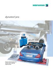
... let us first answer the question ’What<br />
does <strong>unbalance</strong> mean indeed?’.<br />
Unbalance is the heavy spot in the tyre<br />
or rim structure which has been<br />
produced in manufacture (Fig. 1).<br />
Those heavy spots (due to non–uniform<br />
mass distribution) make the wheel <strong>and</strong><br />
steering system vibrate during the ride<br />
unless they are balanced.<br />
Basically we distinguish between<br />
two types of <strong>unbalance</strong>:<br />
1. static <strong>unbalance</strong><br />
2. <strong>dynamic</strong> <strong>unbalance</strong><br />
The difference is easily explained on the<br />
tyre. <strong>Static</strong> <strong>unbalance</strong> exists when the<br />
tyre has one heavy spot (Fig. 2). When<br />
such a tyre is suspended the heavy spot<br />
will tend towards the bottom. This<br />
means static <strong>unbalance</strong> can be determined<br />
without rotation of the wheel.<br />
The contrary applies to <strong>dynamic</strong><br />
<strong>unbalance</strong>. With <strong>dynamic</strong> <strong>unbalance</strong> the<br />
tyre has two heavy spots diagonally<br />
opposed (Fig. 3). If such spots are<br />
equally heavy, they compensate for<br />
each other when the wheel does not<br />
rotate.<br />
But what do you expect the wheel to<br />
behave like once set into rotation:<br />
Fig. 4<br />
a) Will the wheel bounce?<br />
b) Will the wheel wobble?<br />
c) Will the wheel run smoothly?<br />
3
Fig. 4<br />
a) b) c)<br />
Fig. 5<br />
4<br />
Conventional tyre<br />
Fig. 7<br />
Plane separation<br />
Fig. 6<br />
Balance weights 20g 20g<br />
Fig. 8<br />
25g<br />
Dynamic <strong>unbalance</strong> 25g<br />
Wide tyre<br />
40g<br />
30g<br />
30g<br />
re a): The wheel would bounce if it had<br />
static <strong>unbalance</strong>. Dynamic <strong>unbalance</strong><br />
makes the wheel wobble (hence b is<br />
correct).<br />
re b): You are right. A wheel with <strong>dynamic</strong><br />
<strong>unbalance</strong> tends to wobbling once<br />
set into rotation.<br />
re c): As the two heavy spots are<br />
diagonally opposed the wheel will<br />
never allow smooth ride, but tends to<br />
wobbling when set into rotation<br />
(hence b is correct).<br />
Important:<br />
Dynamic <strong>unbalance</strong> is only recognized<br />
when the wheel is set into rotation.<br />
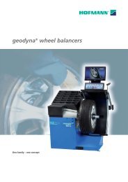
The wider a tyre, the more increases the<br />
effect of <strong>dynamic</strong> <strong>unbalance</strong>, that is the<br />
more wobbling is noticeable during the<br />
ride. Fig. 5 <strong>and</strong> 6.<br />
In this context let us consider the question<br />
of how <strong>and</strong> where static or<br />
<strong>dynamic</strong> <strong>unbalance</strong> can be eliminated.<br />
Important for your underst<strong>and</strong>ing:<br />
State–of–the–art wheel balancers divide<br />
the wheel into two halves, the so–called<br />
planes (Fig. 7).<br />
If the wheel possesses static <strong>unbalance</strong><br />
(one heavy spot of , say, 40 g) that<br />
<strong>unbalance</strong> is compensated for by attaching<br />
each one balance weight of 20 g<br />
left <strong>and</strong> right at the diametrically opposite<br />
sides of the wheel (Fig. 7).<br />
If the wheel possesses <strong>dynamic</strong> <strong>unbalance</strong><br />
(two heavy spots diagonally<br />
opposed) the so–called plane separation<br />
feature is applied: Each wheel plane<br />
(wheel half) is considered separately;<br />
the <strong>dynamic</strong> <strong>unbalance</strong> portion can only<br />
be compensated for diametrically<br />
opposed, that is at the same wheel side,<br />
because otherwise there would another<br />
<strong>unbalance</strong>.<br />
In our example the <strong>unbalance</strong> of 25 g<br />
of the left wheel plane is compensated<br />
for by a balance weight of 25 g<br />
attached to the diametrically opposed<br />
(left) wheel position. The same<br />
procedure is applicable to the right<br />
wheel side (<strong>unbalance</strong> of 30 g) - Fig. 8.
Fig. 9<br />
Fig. 10<br />
Fig. 11<br />
Fig. 12<br />
Heavy<br />
spot<br />
Egg-shaped rim<br />
Heavy spot<br />
(<strong>unbalance</strong>)<br />
Flexible spot<br />
unflexible spot<br />
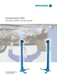
2. Possible causes of<br />
unsmooth ride<br />
In their structure tyres <strong>and</strong> rims possess<br />
a variety of properties that might cause<br />
unsmooth ride:<br />
First possibility:<br />
The rim possesses <strong>unbalance</strong>, that is a<br />
heavy spot, which adversely affects<br />
smooth ride (Fig. 9).<br />
When the wheel is perfectly balanced,<br />
this defect of the rim is completely<br />
compensated for.<br />
Second possibility:<br />
The rim possesses admissible<br />
deformat-ion caused in manufacture -<br />
the so–called egg–shape (Fig. 10).<br />
The unsmooth ride will be noticed<br />
despite of perfect <strong>balancing</strong> of the<br />
wheel (balanced ’egg’).<br />
Third possibility:<br />
The tyre possesses <strong>unbalance</strong>, that is a<br />
heavy spot (Fig. 11).<br />
When the wheel is perfectly balanced<br />
this defect of the tyre is completely<br />
compensated for.<br />
Fourth possibility:<br />
The internal tyre structure presents<br />
more <strong>and</strong> less flexible parts which<br />
means tyre deflection will vary over one<br />
revolution of the wheel, hence during<br />
ride (Fig. 12).<br />
The unsmooth ride will be noticed<br />
despite of perfect <strong>balancing</strong> of the<br />
wheel.<br />
5
6<br />
Fig. 13<br />
Heavy<br />
tyre spot<br />
(<strong>unbalance</strong>)<br />
Fig. 14<br />
Rim<br />
<strong>unbalance</strong><br />
Tyre <strong>unbalance</strong><br />
Balance weight<br />
Heavy<br />
rim spot<br />
(<strong>unbalance</strong><br />
Small<br />
balance weight<br />
3. How to remedy<br />
unsmooth ride<br />
What are now the techniques to<br />
remedy unsmooth ride on a vehicle?<br />
1. Balancing<br />
Tyre <strong>and</strong> rim <strong>unbalance</strong> is determined<br />
during the measuring run <strong>and</strong><br />
compensated for using balance weights<br />
(Fig. 13).<br />
Mind:<br />
Unsmooth ride - due to deformation of<br />
rim <strong>and</strong> non–uniform tyre deflection - is<br />
still possible after <strong>balancing</strong>.<br />
2. Matching<br />
With this technique nowadays used in<br />
garages <strong>and</strong> motor–vehicle workshops<br />
the tyre is readjusted relative to the rim<br />
until tyre <strong>unbalance</strong> <strong>and</strong> rim <strong>unbalance</strong><br />
are opposed <strong>and</strong> then - at least partly -<br />
compensate for each other (Fig. 14).<br />
The small residual <strong>unbalance</strong> thus<br />
achieved will be compensated for with<br />
balance weights.<br />
Mind:<br />
If the position of rim <strong>unbalance</strong> does<br />
not coincide with the position of rim<br />
deformation (which is very likely with<br />
alloy rims), unsmooth ride will still be<br />
possible after <strong>matching</strong>.
Fig. 15<br />
Fig. 16<br />
Fig. 17<br />
Fig. 18<br />
Rim<br />
deformation<br />
– egg -shape<br />
Flexible spot<br />
Unflexible spot<br />
Heavy spot<br />
Highest<br />
rim spot<br />
Heavy unflexible spot of tyre<br />
3. HOFMANN<br />
opto–ride technique<br />
The most important target of this<br />
optimization procedure is to determine<br />
rim deformation, or more precisely the<br />
highest rim spot Fig. 15.<br />
Why this takes three measuring<br />
runs - please see overleaf.<br />
How can rim deformation as<br />
determined be compensated for?<br />
Rim deformation can only be<br />
compensated for by non–uniform tyre<br />
deflection (unflexible tyre spot - in<br />
technical terms radial force variations)<br />
Fig. 16.<br />
As exact determination of those<br />
unflexible tyre spots is only possible<br />
with expensive <strong>and</strong> highly sophisticated<br />
industrial machines.<br />
HOFMANN follows the law<br />
of probability:<br />
In most cases the unflexible tyre spot is<br />
also its heavy spot - Fig. 17.<br />
With the opto–ride technique the<br />
unflexible heavy spot of the tyre is<br />
opposed to the highest spot on the rim<br />
Fig. 18.<br />
Residual tyre <strong>and</strong> rim <strong>unbalance</strong> is then<br />
compensated for with balance weights.<br />
7
8<br />
Fig. 19<br />
First measuring run<br />
Fig. 20<br />
Second measuring run<br />
Fig. 21<br />
Tyre <strong>unbalance</strong><br />
Third measuring run<br />
Fig. 22<br />
Rim <strong>unbalance</strong><br />
Correct<br />
rim centre<br />
Actual<br />
centrebore<br />
Heavy unflexible spot of rim<br />
Optimization<br />
Rim<br />
deformation<br />
Tyre<br />
<strong>unbalance</strong><br />
Highest<br />
rim spot<br />
(Electrically<br />
compensated)<br />
<strong>unbalance</strong><br />
of rim<br />
What will happen in the individual<br />
measuring runs?<br />
Important: The rim must have the same<br />
position before every measuring run<br />
(e g valve in top vertical position).<br />
In a first measuring run the rim alone,<br />
that is without tyre, is measured <strong>and</strong><br />
the <strong>unbalance</strong> determined is<br />
compensated for electrically (will be<br />
added again after the last measuring<br />
run). What is left after the first measuring<br />
run is the effect of deformation of<br />
the rim, which is still unknown (Fig. 19).<br />
In order to determine amount <strong>and</strong><br />
position of rim deformation another<br />
two measuring runs are necessary:<br />
For a second measuring run the tyre is<br />
fitted on the rim <strong>and</strong> the whole<br />
tyre/rim assembly is measured on the<br />
<strong>balancing</strong> machine.<br />
The measured result is composed of<br />
tyre <strong>unbalance</strong> <strong>and</strong> rim deformation<br />
(Fig. 20).<br />
In order to exactly determine rim<br />
deformation, that is the highest spot on<br />
the rim, the tyre has to be readjusted<br />
by 180 degrees relative to the rim<br />
before the third measuring run -<br />
Fig. 2.<br />
This means the highest spot on the rim<br />
is opposed to tyre <strong>unbalance</strong>, which<br />
mostly is the unflexible spot on the tyre<br />
(Fig. 22).<br />
In the final measuring run the rim<br />
<strong>unbalance</strong> previously compensated for<br />
electrically is added again <strong>and</strong> read out<br />
together with the residual <strong>unbalance</strong> of<br />
the tyre (Fig. 22).
A<br />
B<br />
C<br />
D<br />
Let us sum up:<br />
The patented HOFMANN opto–ride<br />
system does not only determine the<br />
<strong>unbalance</strong>s of tyre <strong>and</strong> rim, but also<br />
rim deformation due to manufacture.<br />
Rim deformation is compensated for by<br />
opposing the highest spot on the rim to<br />
tyre <strong>unbalance</strong> (where mostly the most<br />
unflexible tyre spot is located).<br />
With the opto–ride technique<br />
HOFMANN offers the optimum smooth<br />
ride as achievable with garage<br />
equipment <strong>and</strong> is, therefore, able to<br />
satisfy even most sensitive customers<br />
with respect to driving comfort.<br />
Do you think you now have correctly<br />
understood the fundamentals of<br />
optimization?<br />
4. Test your underst<strong>and</strong>ing<br />
of optimization<br />
Which of the four examples given<br />
(A - D) shows the wheel in optimized<br />
condition?<br />
correct rim centre<br />
actual centre–bore<br />
heavy spot (<strong>unbalance</strong>)<br />
unflexible spot<br />
elastic spot<br />
rim deformation<br />
(highest spot on rim)<br />
For the solution see overleaf!<br />
9
A<br />
B<br />
C<br />
Highest<br />
rim spot<br />
D<br />
Highest<br />
rim spot<br />
10<br />
Heavy unflexible spot of tyre<br />
Heavy unflexible spot of tyre<br />
Heavy unflexible spot of tyre<br />
Highest<br />
rim spot<br />
Highest<br />
rim spot<br />
Rim<br />
<strong>unbalance</strong><br />
Tyre <strong>unbalance</strong><br />
A: Either you did not look at the figure<br />
properly, or you have not understood<br />
the optimization procedure correctly.<br />
In figure A the highest spot on the rim<br />
(deformation) is not opposed to the<br />
heavy unflexible spot on the tyre -<br />
hence B is correct.<br />
B: Congratulations! You have the<br />
correct underst<strong>and</strong>ing of what<br />
optimization is like.<br />
Only in this example is rim deformation<br />
(highest spot on rim) opposed to the<br />
heavy unflexible spot of the tyre.<br />
The position of rim <strong>unbalance</strong> does not<br />
import at all for optimization because it<br />
can easily be balanced.<br />
C: May–be you simply made a slip.<br />
When you look at the figure more closely<br />
you will see that rim deformation<br />
(highest spot on rim) <strong>and</strong> the heavy<br />
unflexible spot of the tyre coincide -<br />
whereas they have to be opposed with<br />
an optimized wheel. Hence B is correct.<br />
D: By opposing tyre <strong>and</strong> rim <strong>unbalance</strong>s<br />
(<strong>matching</strong>) residual <strong>unbalance</strong> can be<br />
reduced.<br />
But rim deformation, which is not compensated<br />
for, will continue to adversely<br />
affect smooth ride.<br />
Wheel optimization is shown in Fig. B.
Fig. 23<br />
Fig. 24<br />
Fig. 25<br />
5. On–the–car <strong>balancing</strong><br />
In this last chapter we would like to<br />
study the question why the<br />
finishbalancer (for on–the–car<br />
<strong>balancing</strong>) is an indispensable tool to<br />
achieve optimum ride of every vehicle<br />
despite of previous <strong>off–the–car</strong><br />
<strong>balancing</strong> <strong>and</strong> optimization of the<br />
wheels.<br />
The fundamental difference:<br />
Both off–the–vehicle <strong>balancing</strong> <strong>and</strong> the<br />
HOFMANN opto–ride technique are<br />
"only" able to optimize ride as related<br />
to the wheel - Fig. 23.<br />
The finishbalancer, however, h<strong>and</strong>les<br />
wheels <strong>and</strong> vehicle as one unit - Fig. 24.<br />
Even a perfectly optimized wheel<br />
mostly presents new <strong>unbalance</strong> when<br />
fitted on the vehicle.<br />
It is caused by added manufacturing<br />
tolerances of the vehicle components<br />
such as:<br />
• manufacturing tolerances<br />
of wheel hub<br />
• residual <strong>unbalance</strong>s of hub<br />
• <strong>unbalance</strong>s in brake drum<br />
or brake disc<br />
The HOFMANN finishbalancer<br />
determines the effects of such<br />
manufacturing tolerances of vehicle<br />
components, which might be<br />
transmitted to the wheel <strong>and</strong> produce<br />
new <strong>unbalance</strong>.<br />
With the selective measurement<br />
technique at different speeds<br />
HOFMANN ensures that even with<br />
driven wheels every wheel is considered<br />
singly <strong>and</strong> unaffected by influences of<br />
the opposite wheel - Fig. 25.<br />
If you are interested in details on this<br />
measurement technique, please see our<br />
separate brochure "Precision <strong>balancing</strong><br />
on the vehicle at different speeds".<br />
11
Innovation is our business<br />
Wheel balancers Tyre changers Automotive lifts<br />
Test lanes Wheel aligners Training<br />
Your Hofmann dealer<br />
Snap-on Equipment GmbH<br />
Geschäftsbereich Hofmann Werkstatt-Technik<br />
POB 1202 • 64311 Pfungstadt/Germany<br />
� 06157 12-450 06157 12-229<br />
sales@hofmann-ge.com<br />
www.hofmann-ge.com<br />
9472 102 03.03 Printed in Germany<br />
Technical modifications reserved<br />
certified to<br />
Quality<br />
pays<br />
DIN EN ISO 9001-2000