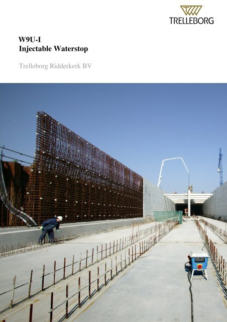
W9U-I Injectable Waterstop - Trelleborg
W9U-I Injectable Waterstop - Trelleborg
W9U-I Injectable Waterstop - Trelleborg

Create successful ePaper yourself
Turn your PDF publications into a flip-book with our unique Google optimized e-Paper software.
<strong>W9U</strong>-I<br />
<strong>Injectable</strong> <strong>Waterstop</strong><br />
<strong>Trelleborg</strong> Ridderkerk BV<br />
10/07 1
Table of contents<br />
Introduction 3<br />
Installation/pouring procedure <strong>W9U</strong>-I waterstop 4<br />
Injection procedure <strong>W9U</strong>-i waterstop 6<br />
Rubberquality 9<br />
Appendix 1 Product drawing <strong>W9U</strong>I-profile. 11<br />
Appendix 2 <strong>Waterstop</strong> with injection pipe. 12<br />
Appendix 3 Situation before pouring (injection system inside formwork). 13<br />
Appendix 4 Situation before pouring (injection system through formwork). 14<br />
Appendix 5 Situation during pouring. 15<br />
Appendix 6 Injection 16<br />
Appendix 7 Design application data 17<br />
This brochure is composed by <strong>Trelleborg</strong> Ridderkerk, in case more information is needed<br />
please consult our sales or technical department at Ridderkerk (The Netherlands).<br />
<strong>Trelleborg</strong> Ridderkerk B.V.<br />
P.O. Box 4007, 2980 GA Ridderkerk, The Netherlands.<br />
Phone: +31 180 49 55 55 Telefax: +31 180 43 30 80<br />
E-mail: bakker@trelleborg.com Internet: www.trelleborgbakker.com<br />
10/07 2
Introduction<br />
When concrete structures are submitted to outside water pressures, in tunnels, cellars, off-shore<br />
reservoirs, etc., the joints between concrete sections are made watertight with waterstops. For<br />
normal purposes our standard rubber waterstop with vulcanised steel strips alongside (type<br />
<strong>W9U</strong>) can be applied.<br />
This waterstop will give water tightness between the concrete and the steel strips. However in<br />
practice, caused by shrinkages in the concrete and errors while pouring, in the area around the<br />
waterstop the concrete can show fissures, gravel spots and the like. These issues can<br />
accommodate water seeping through the concrete. To prevent this leakage, a special type of<br />
waterstop is developed type <strong>W9U</strong>I (see appendix 1).<br />
Alongside the waterstop <strong>W9U</strong> at the ends of the steel strips, a sponge rubber profile is applied.<br />
This sponge rubber is connected every 4 meters with a small steel pipe with an outside diameter<br />
of 12 mm (see appendix 2). When the concrete has been cured and all the shrinkages have been<br />
occurred injection fluid is injected through the injection-pipes. Because of the injection<br />
pressure of 3-10 bar, the sponge on the steel strips will be compressed and so a channel<br />
alongside the steel strips is created. All the fissures, gravel spots etc. around the created<br />
injection channel will be filled with injection fluid and therefore fully impermeable for water<br />
leakages. After total injection operation all possible leakages will be fully sealed.<br />
This brochure contains recommendations for handling, application and injection of the <strong>W9U</strong>-i.<br />
Photo: <strong>W9U</strong>-i on reel<br />
10/07 3
Installation/pouring procedure <strong>W9U</strong>-I waterstop<br />
The <strong>W9U</strong>I should be fixed with the injection sponge directed to the waterside.<br />
In the horizontal part of the joint the waterstop is fixed with its wings bend upwards, to prevent<br />
air to be trapped underneath the waterstop. In the steel strips, at regular intervals, holes are<br />
provided to enable fixing the waterstop with binding wires to the reinforcement bars and or<br />
nails to the formwork (see appendix 5). While removing the formwork the nails have to be<br />
removed too.<br />
Fixing injection system<br />
1. Every 4 meter an injection tube is fastened as indicated on appendix 5. The injection<br />
system consists of 5 parts; injection-pipe, injection-pin, seal bolt and cap. To connect<br />
the injection system to the steel strip a hole has to be drilled through the sponge rubber<br />
and the steel strip (diameter 8,5 mm). We recommend to use a wooden mould for<br />
proper alignment.<br />
2. Adjust the length of injection system according to concrete thickness. In the floor the<br />
injection system can stick out 50 - 100 mm above concrete surface.<br />
3. Apply some Vaseline at inside of cap in order to prevent concrete getting in-between<br />
sponge and cap.<br />
Photo: installed injection system before pouring<br />
10/07 4
4. Apply pin, pipe bolt and seal and connect cap to injection pin.<br />
5. The bolt on the injection pin is tightened. By doing this the injection system is fixed on<br />
the steel strip<br />
6. The pin and pipe are fixed to the reinforcement bars at its proper height. At floor and<br />
roof part it should be possible to move the injection system vertically in order to lift the<br />
sides of the water stop and so prevent trapped air.<br />
7. Check the whole system before pouring<br />
8. After pouring and hardening of the concrete the injection pins can be removed, and the<br />
pipe can be shortened at concrete level. To prevent dirt getting into the pipe we<br />
recommend to close the pipe at the end.<br />
9. To apply the injection system in the walls and roof two procedures can be followed.<br />
The first option is to drill a hole through the casting (see appendix 4). The second<br />
option is to use a PVC cup. When using a cup the injection pin can be situated<br />
underneath the casting so the casting don’t have to be drilled (see appendix 3).<br />
While pouring it is important to avoid air trapped in underneath the waterstop. Therefore the<br />
waterstop in the floor and roof should be installed with the flaps/sides upwards by binding<br />
wires through the pre manufactured holes in the steel strips. The concrete has to be poured till it<br />
reaches the waterstop. With a hook or a similar instrument the waterstop is then pulled, so that<br />
all the air is chased from under the waterstop (see appendix 5). The waterstop is just "pushed<br />
under" then the pouring continues. While pouring, start at one side of the waterstop and<br />
continue as long as possible while pushing the air forward.<br />
To get a waterproof joint it is very important to take good care while pouring the concrete in<br />
the area of the waterstop.<br />
Photo: Injection tubes (orange) sticking out of floor<br />
10/07 5
Injection procedure <strong>W9U</strong>-i waterstop<br />
Conditions<br />
If possible within one year after the pouring of the concrete the <strong>W9U</strong>I must be injected (see<br />
appendix 6). If the term will exceed one year, there is a possibility that the injection sponge will<br />
stick to the concrete. This will cause injection pressures to rise and injecting will be more<br />
difficult.<br />
The waterstops must be injected before the water pressure is activated on the concrete. If not<br />
the injection liquids mixes with water, changing the material quality and diminish the<br />
attachment and filling graduation with the concrete. For detailed information about the<br />
injection resin please contact our office.<br />
During injection there is a possibility injection fluid is getting into the joint and by doing this<br />
filling up the joint. To prevent this we advice to start the injection after (transport-) pre tension<br />
is applied on the tunnel elements.<br />
Injection can be done with a hand-pump (capacity up to 20 bar) during injection the pressure<br />
should not exceed 10 bar.<br />
The injection pressure varies, and depends on the attachment between sponge and concrete, the<br />
viscosity of the epoxy-resin and the injection distance between the injection pipes.<br />
Injection resins<br />
The Dutch public works prefer epoxy resin for preventive injection. In case of weak spots in the<br />
concrete for example caused by gravel spots, epoxy resin will recover and repair the concrete.<br />
Epoxy-polyurethane or polyurethane are regarded as less constructive, and are therefore not<br />
advised for preventive injection. Meanwhile these materials are less sensitive for use in a humid<br />
environment. For corrective purposes the use of these materials can be considered.<br />
Epoxy-resin<br />
• Repairs the concrete<br />
• High compressive strength (select compressive strength > 85 N/mm2)<br />
• In general only to be applied in dry environment<br />
• Very solid after hardening<br />
Specifications of Epoxy resin<br />
• Epoxy resin free of solvents<br />
• Compressive strength > 85 N/mm2<br />
• Viscosity < 150 GP at 25ºC<br />
10/07 6
Tools<br />
The injection tool has to be equipped with a clear manometer with a maximum range of 100<br />
bar. Preferably the maximum pressure has to be adjustable. The fluids should be mixed<br />
mechanically according to regulations of supplier.<br />
Injection procedure<br />
The usage of injection resin depends on the number of gravel spots. Experience in practice<br />
result in a mean usage of 0,2 -0,4 litre/meter.<br />
1. Check if the injection tubes are clean and dry.<br />
2. Starting point of the injection should be in the middle of the floor of the tunnel.<br />
3. Injection is done with two injection teams<br />
4. Team A works to right side and team B works to left side, starting with the floor, then the<br />
walls and finally the roof<br />
5. One joint has to be injected in one phase, therefore make sure there are sufficient spareparts.<br />
6. From the first injection point there has to be injected until the epoxy-resin is shown at the<br />
next injection pipe (maximum pressure = 10 Bar).<br />
7. As soon as the epoxy-resin leaves the next injection pipe, the first injection point should be<br />
shut. Injection should go on from the second injection point. In case the epoxy-resin<br />
exceeds a pressure of 10 bar during 2 minutes one should also close this injection point and<br />
proceed from the next pipe.<br />
8. When from the second injection point the epoxy-resin proceeds from the third injection<br />
point one should close the third injection pipe with a dome nut and go on with injection<br />
from the second point. All the following injection points from which the fluid is coming out<br />
should be shut. In case the proceeding epoxy-resin is coloured white one should wait with<br />
closing the injection pipe until the epoxy-resin has got its natural colour. The white colour<br />
shows that water is mixed with epoxy-resin.<br />
9. As soon as the pressure will become higher as 10 Bar, close the injection point and proceed<br />
at the latest point where the fluid has been shown.<br />
10. If leakages in the dilatation joint are suspected, injection should be stopped until the epoxyresin<br />
is transformed into a gel. Thereafter the pressure can be increased slowly while<br />
checking if the leakage has stopped.<br />
11. If not, extra holes should be drilled to the end of the waterstop and injection should be<br />
started from the extra holes with smaller distances.<br />
12. If during injection-operation no leakages has appeared and the epoxy resin is not leaving<br />
the injection pipes one should drill at 1 meter from the last injection-pipe a hole to the<br />
sponge of the waterstop, and check if there’s epoxy-resin.<br />
13. If not the injection should take place from the new drilled hole (after closing the injection<br />
pipe). If there is epoxy resin, drill a new hole at a distance of 1 meter and repeat the<br />
procedure.<br />
14. After total operation the injection pipes can be shortened and the injection-space can be<br />
filled with mortar.<br />
10/07 7
Photo: Injection with epoxy resin<br />
Check on mixing epoxy resin and harder<br />
Before and during injection small quantities of epoxy resin and harder should be mixed. Make<br />
samples (diameter 50 mm and 2 mm thick) and harden this at 20 °C.<br />
After 24 hours the samples should be hard and not be sticky. Take randomly 2 of these samples<br />
a day.<br />
Data to be registered during Injection<br />
If leakage is occurring in the surroundings of the waterstop, it is very hard to determine what is<br />
causing this leakage. Therefore it is advisable to register the following data during the injection.<br />
• Joint number and position of injection points<br />
• Injection time per injection point<br />
• Type of resin<br />
• Quantity of resin injected per injection point<br />
• Injection points not used for injection<br />
• Start point of injection<br />
• Injection points which are still blocked after 2 minutes of constant pressure<br />
• Outside temperature<br />
• Start time<br />
• Injection pressure(s)<br />
• Breaks during injection (e.g. lunchtime etc)<br />
• End time<br />
10/07 8
Rubber quality<br />
Standard the <strong>W9U</strong>-i are manufactured with Styrene butadiene rubber (SBR).<br />
If this quality is not adequate the following compounds can be used: Chloroprene rubber (CR),<br />
Ethylene Propylene Diene Monomer (EPDM), Natural rubber (NR) or Nitril rubber (NBR)<br />
In view of the long service life required and the fact that waterstops cannot be replaced, the<br />
material has to be of a high quality. Also because injection of leaking joints afterwards is a<br />
costly operation a correct choice of the rubber quality is of paramount importance. The optimal<br />
physical properties of certain rubber compounds depend on the type of rubber elastomer used.<br />
Mechanical Properties<br />
All our waterstops are certified through our own laboratory and will be delivered in accordance<br />
with the Dutch NEN 7030 standard. On request quality-test- certificates can be shown. The<br />
table below shows the NEN 7030 standard.<br />
Polymer SBR<br />
Hardness (°Shore A) 60 ± 5<br />
Tensile strength (N/mm²) ≥ 17,1<br />
Elongation at break (%) ≥ 375<br />
Tear resistance (N) ≥ 31,1<br />
Change after 14 days / 70 °C<br />
Tensile strength (%) ≤ 25<br />
Elongation at break (%) ≤ 30<br />
Hardness (° Shore A) ≤ 8<br />
Compression set 72 hrs 23°C (%) ≤ 10<br />
Water absorption (gr/m²) ≤ 30<br />
Ozone resistance 120 hrs/25 pphm/20°C/20% tear No cracks<br />
Low temperature resistance<br />
Change of hardness at 0 °C (°Shore A) ≤ 5<br />
Change of hardness at -10 °C (°Shore A) ≤ 8<br />
10/07 9
Chemical resistance<br />
In the table underneath the resistance against chemical influences is shown. This list is an<br />
indication to choose a rubber quality. The data is based on a temperature of 20 °C and<br />
concentrated solutions. In case of doubt don’t hesitate to contact us<br />
Quality SBR EPDM CR NR NBR<br />
Natural gas Moderate Moderate Excellent Moderate Excellent<br />
Petroleum Not Not Moderate Not Excellent<br />
Liquefied Ammonia Excellent Excellent Excellent Excellent Excellent<br />
ASTM Oil No. 1 Moderate Not Excellent Not Excellent<br />
ASTM Oil No. 2 Not Not Good Not Excellent<br />
ASTM Oil No. 3 Not Not Good Not Good<br />
Petrol Not Not Good Not Excellent<br />
Brackish Water Excellent Excellent Excellent Excellent Excellent<br />
Diesel Not Not Good Not Excellent<br />
Kerosene Not Not Not Not Excellent<br />
Air from .. till .. ºCelsius -15 till 70 -20 till 110 -10 till 90 -40 till 70 -20 till 70<br />
Mineral Oil Not Not Good Not Excellent<br />
Motor Oil Not Not Excellent Not Excellent<br />
Water till .. ºCelsius 70 110 70 70 70<br />
Weather conditions/Ozone Moderate Excellent Excellent Moderate Moderate<br />
Seawater Moderate Excellent Excellent Moderate Excellent<br />
Sulphuretted hydrogen Not Good Moderate Not Good<br />
Area of application<br />
The final choice for a waterstop is made by desired movement and water pressure in head of<br />
water. Both cause a tension in the rubber. In appendix 7 you will find the design application<br />
data of the <strong>W9U</strong>-I. On the axis the maximum movements in X, Y, and Z direction are given at a<br />
certain pressure of the water (in meters water column).<br />
Z<br />
X<br />
10/07 10<br />
Y
Appendix 1 Product drawing <strong>W9U</strong>I profile<br />
10/07 11
Appendix 2 <strong>Waterstop</strong> with injection pipe.<br />
10/07 12
Appendix 3 Situation before pouring (Injection system inside formwork).<br />
10/07 13
Appendix 4 Situation before pouring (injection system through formwork)<br />
10/07 14
Appendix 5 Situation during pouring.<br />
10/07 15
Appendix 6 Injection.<br />
10/07 16
Appendix 7. Design application data<br />
10/07 17