Metal bellows coupling I Series KPP - Jakob GmbH & Co ...
Metal bellows coupling I Series KPP - Jakob GmbH & Co ...
Metal bellows coupling I Series KPP - Jakob GmbH & Co ...

You also want an ePaper? Increase the reach of your titles
YUMPU automatically turns print PDFs into web optimized ePapers that Google loves.
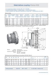
Technical data:<br />
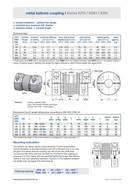
metal <strong>bellows</strong> <strong>coupling</strong> I <strong>Series</strong> KPH / KMH / KRH<br />
simple installation - splitted hub design<br />
backlash free, torsional stiff, fl exible<br />
stainless design variable length<br />
KPH nominal moment torsional stiff ness max. lateral shaft axial spring lateral spring mass<br />
KMH torque of inertia [Nm/arcmin] displacement [mm] rate [N/mm] rate [N/mm] approx.<br />
KRH [Nm] [10-3kgm2 Size<br />
] KPH KMH KRH KPH KMH KRH KPH KMH KRH KPH KMH KRH [kg]<br />
10 10 0,02 1,7 1,1 - 0,15 0,25 - 70 45 - 60 224 - 0,1<br />
40 40 0,2 9 5,8 10 0,2 0,25 0,2 70 51 170 190 450 170 0,5<br />
80 80 0,5 14 8,7 12 0,2 0,3 0,3 70 49 95 260 650 80 0,8<br />
200 200 1,2 25 17 30 0,2 0,3 0,3 98 80 120 470 1000 120 1,2<br />
400 400 3,0 74 47 80 0,2 0,3 0,3 135 100 260 640 1500 260 2,0<br />
• Three types: Type KPH with 4-corrugation <strong>bellows</strong> / Type KMH mit 6-corrugation <strong>bellows</strong> / Type KRH mit 2x 1-corrugation <strong>bellows</strong>.<br />
• Note: <strong>Co</strong>upling types in splitted hub design for higher torques or rather shorter length see series KGH.<br />
KPH<br />
Material: <strong>bellows</strong>: stainless steel<br />
hubs: high tensile strength aluminium<br />
screws: ISO 4762 – nickel plated<br />
Dimensions [mm]: length dimensions according to DIN ISO 2768 cH<br />
KPH<br />
KMH<br />
KRH<br />
Øa* c f<br />
g g g<br />
KPH KMH KRH<br />
h<br />
L L L<br />
KPH KMH KRH<br />
t<br />
ØD1/2<br />
min<br />
ØD1/2<br />
max<br />
10 35 21 M5 - 8 Nm 33 43 - 9 73 83 - 18 6 15<br />
40 58 36 M8 - 25 Nm 39 48 51 13 95 104 107 26 9 25<br />
80 75 47 M10 - 65 Nm 41 51 59 13 97 107 115 26 12,5 35<br />
200 89 56 M12 - 115 Nm 45,5 57,5 73 14 106 118 134 28 19 42<br />
400 109 72 M14 - 185 Nm 52,5 67,5 84 15 117 132 149 30 24 55<br />
* The projecting edge of the screw head is considered at outer diameter “a“<br />
Mounting instruction:<br />
The splitted hub design allows a easy assembly. Further simplifi cation<br />
during installation is provided because one half of the split hub is put onto<br />
the pipe. This allows that the <strong>coupling</strong> can rest on the two shaft ends.<br />
The second half of the split hub can then be mounted to the <strong>coupling</strong> by<br />
screwing it on from below with the specifi ed tightening torque. This feature<br />
makes a “one man assembly” possible. Important is the distance between<br />
the shafts must be bigger than dimension g!<br />
Ordering example:<br />
www.jakobantriebstechnik.de<br />
KPH 80 - D1 = Ø24 G7 D2 = Ø30 G7<br />
KMH 400 - D1 = Ø38 F6 D2 = Ø48 F6<br />
Servo <strong>coupling</strong>s 13