Data sheet
Data sheet
Data sheet

You also want an ePaper? Increase the reach of your titles
YUMPU automatically turns print PDFs into web optimized ePapers that Google loves.
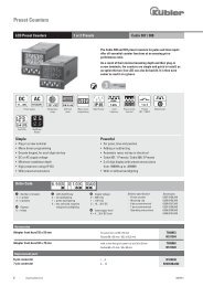
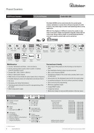
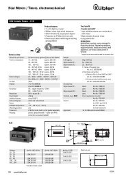
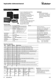
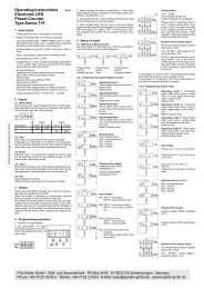
Preset counter electronic<br />
Programming:<br />
The types 903 and 904 are programmed via only 4 keys on the<br />
front side. Trouble-free and intuitive operation through clear<br />
text user guidance on the display. The operating parameters<br />
are chosen from a menu. The device can be used as:<br />
1. Pulse counter<br />
2. Frequency meter<br />
3. Time meter<br />
Therefore the following functions are programmable:<br />
Polarity of the inputs:<br />
Positive (pnp) or negative (npn) polarity of the inputs. The<br />
selected polarity applies to all inputs.<br />
Operating modes, impulse counter and timer:<br />
– adding, starting at zero<br />
– subtracting, starting at the preset value (903)<br />
or at preset value 2 (904)<br />
– adding with automatic reset to zero at preset value (903)<br />
or preset value 2 (904)<br />
– subtracting with automatic reset to preset value (903)<br />
or preset value (904) at zero.<br />
Input modes, impulse counter and frequency meter:<br />
E1 1 count input, 1 count direction input<br />
E2 1 Count input up<br />
1 Count input down<br />
E3 Quadrature input<br />
to connect encoders with 2 signals shifted by 90°<br />
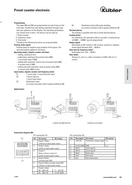
Applications:<br />
7/2007<br />
E4 Quadrature input with pulse doubling<br />
to connect encoders with 2 signals shifted by 90°<br />
Decimal places:<br />
The display is possible with two or three decimal places<br />
Scaling factor:<br />
For optimizing the operation with an encoder a scaling factor<br />
of 0.0001 ... 9.9999 may be programmed<br />
Output signal:<br />
Selectable as NO contact or NC contact, positive or negative<br />
timed signal (duration 0.01 ... 99.99 s)<br />
Gate time for frequency meter:<br />
Selectable from 0.01 ... 99.99 s<br />
Hour meter:<br />
Timing in h, min or s, with a resolution of 0.001, 0.01, 0.1 or<br />
h:min:s<br />
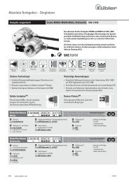
control via light barrier control via encoder<br />
Connection diagram 904:<br />
Pin connection X1: Pin connection X2:<br />
Pin Description AC version DC version<br />
1 +24 V DC Transmitter voltage supply n.c.<br />
Pin AC version DC version<br />
1 Output 1 Relay<br />
collector at optocoupler output<br />
2 Output 1 Relay<br />
emitter at optocoupler output<br />
3 Output 2<br />
Relay common contact (c)<br />
emitter at optocoupler output<br />
4 Output 2 Relay<br />
normally open (NO)<br />
5 Output 2 Relay normally closed (NC)<br />
collector at optocoupler output<br />
6 Supply voltage<br />
90 ... 260 V AC 11 ... 30 V DC<br />
7 90 ... 260 V AC 0 V DC (GND)<br />
2 0 V DC (GND) GND n.c.<br />
3 INP A Count input A<br />
4 INP B Count input B<br />
5 Reset Reset input<br />
6 Gate Gate input<br />
7 Key Key locking input<br />
www.kuebler.com 135<br />
Preset counters