Olympus POM Polarizing Microscope instructions
Olympus POM Polarizing Microscope instructions
Olympus POM Polarizing Microscope instructions

You also want an ePaper? Increase the reach of your titles
YUMPU automatically turns print PDFs into web optimized ePapers that Google loves.
2 I<br />
INSTRUCTIONS<br />
FOR<br />
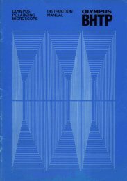
OLYMPUS POLARIZIING MICROSCOPE MODEL <strong>POM</strong><br />
The polarizing microscope is a useful instrument to study optical characteristics<br />
of materials by means of polarized light.<br />
A standard microscope is used to observe shades and colors of a speci men by<br />
trans·illumination or vertical illumimation.<br />
The polarizing microscope further enables the user to observe the optical char.<br />
acteristics of the specimen and to recognize more detailed data. Therefore, even<br />
an extremely minute article may be made an cbject of the observation. In some<br />
cases, based on the optical caracteristics thus obtained, even the chemical elements<br />
of the specimen can be conjectured.<br />
For this reason, a polarizing microscope is widely utilized for the optical<br />
observation and research not only in the field of mineralogy and petrology, but<br />
also in chemistry, pharmacy, biology, medical science, and ceramics, as well as in<br />
chemical and textile industries.<br />
The <strong>Olympus</strong> <strong>Polarizing</strong> <strong>Microscope</strong> Model <strong>POM</strong> is with an inclined head. It<br />
is equipped with the excellent objective lenses ot 4X to 200X magnifications and<br />
various attachments.<br />
)
+ NAME OF PARTS<br />
eyepiece<br />
tube length<br />
adjusting ring<br />
Bertland lens<br />
fixing ring<br />
Bertland lens<br />
centering knob<br />
Tube fixing ring<br />
Angle Indicator<br />
Dial<br />
Test plate Inserting<br />
Winodw<br />
Stuge plate<br />
Clip<br />
Stage Clamp<br />
Fine Adj. HJndle<br />
Clamping lever' for<br />
Coarse Adjustment<br />
Coarse adjustment.<br />
arm.<br />
Objectives<br />
standard Test plates<br />
iris diaphragm<br />
Ifor conoscopic ubs.l<br />
Bertland lens centering<br />
knob<br />
Inserting & Rotating<br />
Lever for Analyzer<br />
Centering knob for<br />
objective<br />
Objective<br />
Rotating Stage<br />
Vernier<br />
Iris Diaphragn Lever<br />
Swing out knob<br />
Polarizer Rotating dial.<br />
Substage condenser dial.<br />
mirror<br />
Base<br />
Eyepieces
)<br />
+ OPTICAL PATH -<br />
)<br />
mirror
mirror<br />
Test plates<br />
+ ASSEMBLY<br />
Attochment Container<br />
ceder Filter<br />
oil<br />
Objective<br />
Attachment<br />
Container<br />
Sp.<br />
Rox<br />
condenser<br />
tube<br />
Contained in the Allochment<br />
Container are:<br />
Key<br />
Tube<br />
Condenser<br />
Reflector (mirror!<br />
Objectives<br />
Eyepieces<br />
Test Plates<br />
Clips<br />
Ceder Oil<br />
Filter<br />
Certificate<br />
of Inspection<br />
frames<br />
1<br />
1<br />
1<br />
5<br />
3<br />
2<br />
2<br />
1 btl.<br />
1. Remove fixing screws and frames to take out the body from the<br />
cabinet.<br />
2. Take the tube from the Attachment Container and set it onto the<br />
body. Turn the fixing ring till it no further goes,<br />
3. Attach the condenser, the objective, and the evepiece in the same<br />
order as in th'e case of a standard microscope.<br />
4, Fix the reflector and clips.<br />
5, Also included in the Attachment Container are a bottle of ceder oil )\<br />
and a filter. Use them as required during the observation,<br />
1<br />
.) j
)<br />
+ CAUTIONS:<br />
1. A sudden change in humidity and temperature causes moisture on<br />
the surface of the lens, resulting into the hazy effect during an<br />
observation. It further brings about mildews and corrosion'. In<br />
general, a high temperature is not preferrable.<br />
2. Avoid giving a severe impact to the instrument. The very fine adjust.<br />
ment may be ruined. Be sure to carry the instrument carefully.<br />
3. After its use, wipe off ceder oil at the tip of the objective with a<br />
piece of gauze soaked with xylene; if anisole is used, simply clean<br />
it with a piece of dry gauze. Any trace of oil left on the surface<br />
of the lens will cause an adverse effect on it.<br />
4. Dust, along with humidity, will also cause an adverse effect and<br />
mildews on the lens. The instrument is dust-proof but an utmost<br />
precaution will never do a harm. Especially, dust accumulated in<br />
the optical path from the polarizer to the analyzer, will cause the<br />
bi.refringence resulting inlo a low contrast. After the use, therefore<br />
be sure to cover it with the alastic cover provided. If it is not to<br />
be used for a long time, return it to the cabinet.<br />
5. The polarizing filters used for the polarizer and the analyzer will<br />
become inferior in its efficiency if exposed to the temperature over<br />
60°(. It is risky to expose it to sunshine or to the strong illumina-.<br />
tion for a prolonged time.<br />
6. A microscope is a very finely adjusted instrument. Refrain from<br />
disassembling the mechanical parts. Particularly the optical system<br />
requires a rigid and minute adjustment and, therefore, must<br />
absolutely be left to the specialist. In case of any neeessity for<br />
repair, please contact our company or our agents.
)<br />
+ BODY<br />
Circular Rotating Stage:<br />
Mechanica I Stage !cross-movement);<br />
Outer diameter-140mm; the stage plate outer diameter-60mm. the<br />
inner diameter-15mm; smooth rotation by means of ball-bearings; with<br />
360 0<br />
scale and J/20° verniers; may be cL!mped at any position; 4 holes<br />
for clip fixing. 3 holes for mechanical stage setting, 2 holes for universal<br />
stage setting; a ring provided at the bottom of the stage for the<br />
connecting rod for the analyzer and the polarizer.<br />
The mechanical stage IS attached to the rotating stage. Then a<br />
slide glass is set onto it and the portion of the specimen to be examined<br />
is aligned with the center of the rotating stage. The maximum<br />
range of movement. in four directions-back & forth and left & right.<br />
is 30mm each and readings may be obtained as small as O.lmm on<br />
verniers: In such a case as the observation of ores by the vertical<br />
illumination, first fix the specimen on tbe slide glass by rubber. etc.,<br />
and set tbe glass onto the mechanical stage. The bandpress for the<br />
metallurgical microscope can be used to prepare a specimen.
+ BODY<br />
Iris Diaphragm:<br />
When the Bertland lens is inserted<br />
the specimen forms its image at the<br />
vicinity of the iris diaphragm lin the<br />
middle of the head!. When an observ<br />
er's interest is centered at a certain<br />
portion of the specimen, this diaphragm<br />
is used to cover up the unnecessary<br />
portions.<br />
.Inserting Ond Rotating Lever for the<br />
Analyzer:<br />
When the lever is pulled out to the<br />
fullest, the analyzer is set in the optical<br />
path. It can he rotated throngh 90°<br />
as illustrated. The analyzer is usually<br />
kept in the optical path during the<br />
observation, except for a standard<br />
observation.<br />
When the lever is pushed in as<br />
illustrated, the analyzer will not work<br />
and this is the position used for a<br />
normal observation.<br />
Head:<br />
The inclined head with an angle of 30°,<br />
when the instrument is placed on a desk of the<br />
normal height, avails the observer a comfortable<br />
of the observation, as the eyepiece will position<br />
at the height of approximately 36el1l from the<br />
bed.<br />
Bertland Lens:<br />
Set at the iower part of the inclined head<br />
is the shifting knob for the Bertland lens along<br />
with its centering knob. With this lens on, the<br />
interferential figure formed at the back focusing<br />
plain of the objective mav be observed.<br />
)
life BODY<br />
Test Plates:<br />
+ SPECIAL ACCESSORIES:<br />
Berek Compensator:<br />
Insert the 1/4 wave length retardation plate Imica 147m,1'l or the<br />
ting plate Igypsum 530m/1) into the provided windw at an angle of 45°.<br />
They are used for examiation of the bi-refringence or warps and for<br />
determination of the axis.<br />
Angle Indicator Dial.<br />
A piece of calcite is set in this compensator to measure the<br />
bi-refringence of the specimen. The compensator is inserted into the<br />
test plate window. Readings taken from the angle indicator dial<br />
combined with the data taken from the attached compensation curve<br />
table will determine the retardation.<br />
A bi-refringent specimen may be set at the extinct position stage<br />
45° by the scale and clamp it at the diagonal posittion. Then insert<br />
the compensator, turn the dial until the interferential color in zero<br />
order appears in the center of the field. Take the reading of the<br />
angle. Compare it on the compensation curve and obtain the micron<br />
valus of the retardation. If the order doesn't lessen even by turning<br />
the compensation dial, turn the specimen 90° and repeat the same<br />
procedure.<br />
At the position of 30° on the indicator dial, the tcst plate will<br />
become perpendicular to the optical axis with 0 retardation; therefore,<br />
insertion and removal of the test plate is performed at this position.<br />
If it is overly slanted it will get stuck at the inserting window.<br />
Eyepiece Adaptor.<br />
If the observer prefers to use an evepiece of<br />
a standard microscope [with a smaller .lIS diameten,<br />
he may remove the ['O\'[ eyepiece and replace<br />
with this adaptor. Then the normal evepiece may<br />
be inserted in it. This will make possible the<br />
of the general eyepieces, grain-size measuring<br />
evepieces, other specialized eyepieces.
+ OBSERVATION METHODS:<br />
Standard:<br />
When the instrument is to be used as (standardl microscope, the<br />
polarizer, test plate, and the Bertland lens are riot necessry. In principle<br />
those are to be removed from the optical path, but ordinarily the pola<br />
rizer is left in operation.<br />
Orthoscopic:<br />
With the microscope properly set for this type of the observation,<br />
only the light passing in almost parallel to the optical axis will enter<br />
the view field, thus enabling the user to observe the optical characteris<br />
tics of the specimen in that direction.<br />
In principle the parallel light source is to be applied, but since this<br />
will darken the field and lower the resolving power of the lens extreme·<br />
Iy, it may be alluminated by allowing the low aperture at the lower<br />
condenser lens only Iswinging out the top lensl. Therefore, mainly the<br />
low magnification objectives of 20X, or under, are utilized. It is reco<br />
mmended to adjust the contrast by means of the aperLure diaphragm<br />
at the bottom of the condenser in accordance with the objective used.<br />
The centering knob on the objective fixing ring can be utilized to<br />
align the center of the specimen with that of the view field.<br />
Conosopic:<br />
It is necessary to illuminate the specimen by corn lighting. Put the<br />
top condenser lens back into the position, then attach a high magnifica<br />
tion objective, such as 40X or lOOX. After appropriate foc'(ising on the<br />
specimen, insert the Bertland lens and now focus on the interferential<br />
fringe formed at the back focusing plain of the objective lbcteer known<br />
as the conoscopic image}. by helicoid movement of the tube.<br />
Also a pin.hole cap may be used in place of an eyepiec