Expo-Telektron Safety Systems MiniPurge Z & Y Purge Manual ...
Expo-Telektron Safety Systems MiniPurge Z & Y Purge Manual ...
Expo-Telektron Safety Systems MiniPurge Z & Y Purge Manual ...

Create successful ePaper yourself
Turn your PDF publications into a flip-book with our unique Google optimized e-Paper software.
<strong>Expo</strong>-<strong>Telektron</strong> <strong>Mini<strong>Purge</strong></strong> Z purge Handbook ML 307 Issue A Page 5-2<br />
5.4.1 Control Unit (CU)<br />
The control unit is at the heart of the system. It contains a pneumatic logic circuit specially<br />
designed and built to control the functions required for purge and pressurization. For all<br />
systems this includes pressure and purge flow measurement, and local visual indication of<br />
alarm/pressurized and flow sensed. It also provides the output for remote alarm<br />
corresponding to the output type selected.<br />
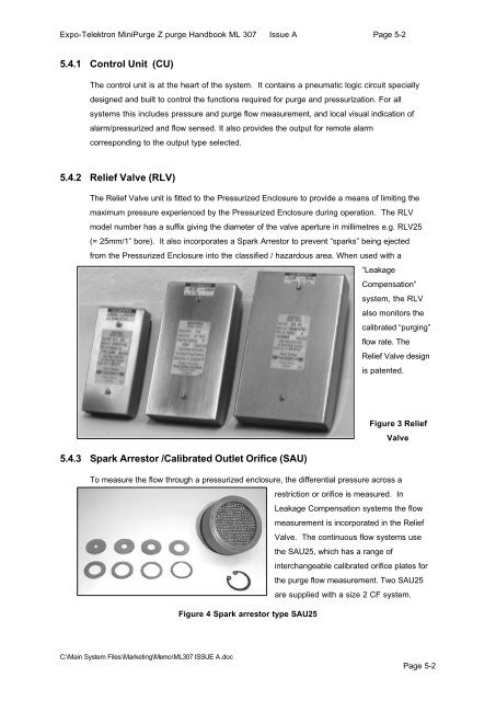
5.4.2 Relief Valve (RLV)<br />
The Relief Valve unit is fitted to the Pressurized Enclosure to provide a means of limiting the<br />
maximum pressure experienced by the Pressurized Enclosure during operation. The RLV<br />
model number has a suffix giving the diameter of the valve aperture in millimetres e.g. RLV25<br />
(= 25mm/1” bore). It also incorporates a Spark Arrestor to prevent “sparks” being ejected<br />
from the Pressurized Enclosure into the classified / hazardous area. When used with a<br />
5.4.3 Spark Arrestor /Calibrated Outlet Orifice (SAU)<br />
C:\Main System Files\Marketing\Memo\ML307 ISSUE A.doc<br />
“Leakage<br />
Compensation”<br />
system, the RLV<br />
also monitors the<br />
calibrated “purging”<br />
flow rate. The<br />
Relief Valve design<br />
is patented.<br />
Figure 3 Relief<br />
To measure the flow through a pressurized enclosure, the differential pressure across a<br />
Figure 4 Spark arrestor type SAU25<br />
Valve<br />
restriction or orifice is measured. In<br />
Leakage Compensation systems the flow<br />
measurement is incorporated in the Relief<br />
Valve. The continuous flow systems use<br />
the SAU25, which has a range of<br />
interchangeable calibrated orifice plates for<br />
the purge flow measurement. Two SAU25<br />
are supplied with a size 2 CF system.<br />
Page 5-2