8818 - BK Medical
8818 - BK Medical
8818 - BK Medical

Create successful ePaper yourself
Turn your PDF publications into a flip-book with our unique Google optimized e-Paper software.
English<br />
BB1505-F<br />
June 2012<br />
Biplane and Endfire Transducer<br />
User Guide<br />
Type <strong>8818</strong><br />
For Professional Users Only
<strong>BK</strong> MEDICAL<br />
Mileparken 34<br />
2730 Herlev<br />
Denmark<br />
Tel.:+45 4452 8100 / Fax:+45 4452 8199<br />
www.bkmed.com<br />
Email: info@bkmed.dk<br />
The serial number of a <strong>BK</strong> <strong>Medical</strong> product contains information about the year of manufacture.<br />
To obtain the date of manufacture of a product, please contact your <strong>BK</strong> <strong>Medical</strong> representative or write<br />
to us at the email address above, including the product’s serial number (SN number).<br />
<strong>BK</strong> <strong>Medical</strong> Customer Satisfaction<br />
Input from our customers helps us improve our products and services. As part of our customer<br />
satisfaction program, we contact a sample of our customers a few months after they receive their orders.<br />
If you receive an email message from us asking for your feedback, we hope you will be willing to<br />
answer some questions about your experience buying and using our products. Your opinions are<br />
important to us. You are of course always welcome to contact us via your <strong>BK</strong> <strong>Medical</strong> representative or<br />
by contacting us directly.<br />
If you have comments about the user documentation, please write to us at the email address above.<br />
We would like to hear from you.<br />
© 2012 <strong>BK</strong> <strong>Medical</strong><br />
Information in this document may be subject to change without notice.
Contents<br />
Introduction . . . . . . . . . . . . . . . . . . . . . . . . . . . . . . . . . . . . . . . . . . . . . . . . . . . . . . 5<br />
Indications for Use . . . . . . . . . . . . . . . . . . . . . . . . . . . . . . . . . . . . . . . . . . . . . 5<br />
General Information . . . . . . . . . . . . . . . . . . . . . . . . . . . . . . . . . . . . . . . . . . . . . . . 6<br />
Service and Repair . . . . . . . . . . . . . . . . . . . . . . . . . . . . . . . . . . . . . . . . . . . . . 7<br />
Caring for the Transducer. . . . . . . . . . . . . . . . . . . . . . . . . . . . . . . . . . . . . . . . 7<br />
Cleaning and Disinfection . . . . . . . . . . . . . . . . . . . . . . . . . . . . . . . . . . . . . . . . . . . 7<br />
Starting Imaging . . . . . . . . . . . . . . . . . . . . . . . . . . . . . . . . . . . . . . . . . . . . . . . . . . 7<br />
Connecting the Transducer. . . . . . . . . . . . . . . . . . . . . . . . . . . . . . . . . . . . . . . 7<br />
Changing Frequency. . . . . . . . . . . . . . . . . . . . . . . . . . . . . . . . . . . . . . . . . . . . 8<br />
Using a Transducer Cover . . . . . . . . . . . . . . . . . . . . . . . . . . . . . . . . . . . . . . . 8<br />
Using the Transducer Control Button. . . . . . . . . . . . . . . . . . . . . . . . . . . . . . . 8<br />
Changing Orientation . . . . . . . . . . . . . . . . . . . . . . . . . . . . . . . . . . . . . . . . . . . 8<br />
Imaging with Type <strong>8818</strong> . . . . . . . . . . . . . . . . . . . . . . . . . . . . . . . . . . . . . . . . . . . . 9<br />
Imaging Without Puncture or Biopsy. . . . . . . . . . . . . . . . . . . . . . . . . . . . . . . 9<br />
Contrast Imaging . . . . . . . . . . . . . . . . . . . . . . . . . . . . . . . . . . . . . . . . . . . . . 10<br />
Adjusting Image Area and Using Expanded Sector (Trapezoidal View). . . 10<br />
Puncture and Biopsy Facilities . . . . . . . . . . . . . . . . . . . . . . . . . . . . . . . . . . . . . . 10<br />
For Transrectal Puncture . . . . . . . . . . . . . . . . . . . . . . . . . . . . . . . . . . . . . . . 11<br />
For Transperineal Puncture . . . . . . . . . . . . . . . . . . . . . . . . . . . . . . . . . . . . . 15<br />
Performing Puncture and Biopsy . . . . . . . . . . . . . . . . . . . . . . . . . . . . . . . . . 16<br />
Cleaning after Puncture and Biopsy . . . . . . . . . . . . . . . . . . . . . . . . . . . . . . . 17<br />
3D Imaging . . . . . . . . . . . . . . . . . . . . . . . . . . . . . . . . . . . . . . . . . . . . . . . . . . . . . 17<br />
Magnetic Wheel Mover UA0513. . . . . . . . . . . . . . . . . . . . . . . . . . . . . . . . . 17<br />
Variable Friction Support Arm UA0553 . . . . . . . . . . . . . . . . . . . . . . . . . . . 17<br />
Disposal . . . . . . . . . . . . . . . . . . . . . . . . . . . . . . . . . . . . . . . . . . . . . . . . . . . . . . . . 17<br />
3
Introduction<br />
This is the user guide for Type <strong>8818</strong> and must be used together with Care, Cleaning<br />
& Safety which contains important safety information.<br />
Indications for Use<br />
Biplane and Endfire Transducer Type <strong>8818</strong> combines simultaneous biplane imaging<br />
and endfire imaging in a single transducer. Type <strong>8818</strong> is designed for transrectal<br />
procedures.<br />
WARNING<br />
The tip of the <strong>8818</strong> transducer (the part containing the arrays) is very delicate. Handle the<br />
transducer gently, especially when you put it down on a hard surface, for example. Also be<br />
very careful not to bump the tip.<br />
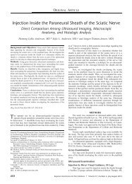
Figure 1. Type <strong>8818</strong>.<br />
Imaging Plane<br />
Transverse button<br />
Sagittal/Endfire<br />
button<br />
<strong>8818</strong> contains two convex arrays — one for transverse imaging, and one for sagittal and<br />
endfire imaging. The sagittal array of the <strong>8818</strong> has a total arc of 210°. In both<br />
simultaneous biplane imaging and endfire imaging, the imaging plane uses a 140°<br />
section of the arc. It is important to note that simultaneous biplane imaging and<br />
endfire imaging use different sections of the sagittal array. Figure 2 illustrates which<br />
section of the array simultaneous biplane and endfire use.<br />
<strong>8818</strong> User Guide (BB1505-F) Introduction 5<br />
Tip
General Information<br />
Figure 2. Imaging plane for Type <strong>8818</strong>.<br />
Product specifications for this transducer can be found in the Product Data sheet that<br />
accompanies this user guide.<br />
Acoustic output data and data about EMC (electromagnetic compatibility) for this<br />
transducer are in Technical Data (BZ2100) that accompanies this user guide. A full<br />
explanation of acoustic output data is given in your system user guide.<br />
WARNING<br />
Simultaneous biplane portion of sagittal array<br />
Transverse array<br />
Endfire portion of sagittal array<br />
Transverse array<br />
If at any time the system malfunctions, or the image is severely distorted or degraded, or you<br />
suspect in any way that the system is not functioning correctly:<br />
• Remove all transducers from contact with the patient.<br />
• Turn off the system. Unplug the system from the wall and make sure it cannot be used<br />
until it has been checked.<br />
• Do not remove the system cover.<br />
• Contact your <strong>BK</strong> <strong>Medical</strong> representative or hospital technician.<br />
WARNING<br />
Always keep the exposure level (the acoustic output level and the exposure time) as low as<br />
possible.<br />
6 June 2012 <strong>8818</strong> User Guide (BB1505-F)
Service and Repair<br />
WARNING<br />
Caring for the Transducer<br />
The transducer may be damaged during use or processing, so it must be checked<br />
before use for cracks or irregularities in the surface. It should also be checked<br />
thoroughly once a month following the procedure in Care, Cleaning & Safety.<br />
Cleaning and Disinfection<br />
Starting Imaging<br />
Service and repair of <strong>BK</strong> <strong>Medical</strong> electromedical equipment must be carried out only by the<br />
manufacturer or its authorized representatives. <strong>BK</strong> <strong>Medical</strong> reserves the right to disclaim all<br />
responsibility, including but not limited to responsibility for the operating safety, reliability<br />
and performance of equipment serviced or repaired by other parties. After service or repairs<br />
have been carried out, a qualified electrical engineer or hospital technician should verify the<br />
safety of all equipment.<br />
To ensure the best results when using <strong>BK</strong> <strong>Medical</strong> equipment, it is important to<br />
maintain a strict cleaning routine.<br />
Full details of cleaning and disinfection procedures can be found in Care, Cleaning<br />
& Safety that accompanies this user guide. A list of disinfectants and disinfection<br />
methods that the transducer can withstand are listed in the Product Data sheet.<br />
Sterile covers are available. See the Product Data sheet for more information.<br />
WARNING<br />
Users of this equipment have an obligation and responsibility to provide the highest possible<br />
degree of infection control to patients, co-workers and themselves. To avoid cross<br />
contamination, follow all infection control policies for personnel and equipment that have<br />
been established for your office, department, or hospital.<br />
All equipment must be cleaned and disinfected before use.<br />
Connecting the Transducer<br />
WARNING<br />
Keep all plugs and sockets absolutely dry at all times.<br />
The transducer is connected to the system using the array Transducer Socket on the<br />
system. To connect, the transducer plug’s locking lever should first be in a horizontal<br />
position. Align the plug to the system socket and insert securely. Turn the locking<br />
lever clockwise to lock in place.<br />
When connected, the transducer complies with Type BF requirements of EN60601-1<br />
(IEC 60601-1).<br />
<strong>8818</strong> User Guide (BB1505-F) Cleaning and Disinfection 7
Changing Frequency<br />
The Multi-Frequency Imaging (MFI) facility enables you to select the imaging<br />
frequency. See the applicable system user guide for instructions. The selected<br />
frequency is displayed at the top of the screen.<br />
Using a Transducer Cover<br />
The transducer should be enclosed in a transducer cover or a standard condom. See<br />
the Product Data sheet for a list of available transducer covers.<br />
WARNING<br />
Because of reports of severe allergic reactions to medical devices containing latex ( natural<br />
rubber), FDA is advising health-care professionals to identify their latex-sensitive patients<br />
and be prepared to treat allergic reactions promptly.<br />
Apply sterile gel to the tip of the transducer or fill the cover with 1 to 2 ml of sterile<br />
water. This improves the screen images by preventing image artifacts caused by air<br />
bubbles.<br />
Pull the transducer cover over the transducer.<br />
Gel also creates a good acoustic contact between the skin and the transducer;<br />
therefore, apply a small amount to the outside of the cover prior to imaging. Re-apply<br />
the gel frequently to ensure good screen images.<br />
WARNING<br />
Use only water-soluble agents or gels. Petroleum or mineral oil-based materials may harm<br />
the cover materials.<br />
WARNING<br />
Do not use excessive force during insertion. Do not make excessive lateral movements<br />
during or after insertion. Risk of injury or tissue damage to the patient could occur under<br />
certain circumstances. A digital palpation of the rectum may need to be carried out by a<br />
clinician prior to insertion or use of the probe as a precautionary measure.<br />
Using the Transducer Control Button<br />
To change the imaging plane, press the button corresponding to that plane (see Figure<br />
1). Pressing the button activates (starts) or freezes (stops) imaging in that plane. One<br />
button enables the sagittal or longitudinal array. A long press on this button also<br />
activates endfire imaging. A second button enables the transverse array. Each time a<br />
button is pressed, a beep is emitted.<br />
Changing Orientation<br />
To change the orientation of the image on the monitor, refer to the applicable system<br />
user guide for instructions.<br />
8 June 2012 <strong>8818</strong> User Guide (BB1505-F)
Imaging with Type <strong>8818</strong><br />
Simultaneous Biplane Imaging<br />
<strong>8818</strong> can transmit transverse (T) and sagittal (S) images simultaneously. When you<br />
press the system’s Split key, simultaneous live transmission is automatically<br />
activated. On the screen, this is indicated by a green dot in front of Simultan.<br />
Transverse or Sagittal Imaging<br />
Click Simultan to toggle simultaneous live transmission on or off. When<br />
simultaneous transmission is off, you can change which plane is active and which is<br />
frozen by pressing the Split key or by placing the cursor on the image you want to<br />
be active and pressing the Select key.<br />
Endfire Imaging<br />
Type <strong>8818</strong> can perform endfire imaging. A long press on the transducer’s<br />
Sagittal/Endfire button activates endfire imaging. On the screen, this is indicated<br />
by the letter E, which appears to the right of the transducer number. To switch<br />
imaging plane, click E and select transverse (T) or sagittal (S).<br />
When you activate endfire imaging, one image appears (and by default, simultaneous<br />
imaging is off). You must enable split screen imaging as there is no defined isocenter<br />
in this context. When you press the system’s Split key, two images appear on the<br />
screen. The endfire image appears and either a transverse or sagittal image appears,<br />
depending on what was last used during imaging.<br />
Click Simultan to toggle simultaneous live transmission on or off.<br />
Imaging Without Puncture or Biopsy<br />
When <strong>8818</strong> is used for transrectal imaging without the puncture facilities, the dummy<br />
bracket UA1325 must be in place. This clicks into position on the transducer to cover<br />
the open channel (see Figure 3).<br />
Figure 3. Type <strong>8818</strong> and the dummy channel bracket UA1325.<br />
Note: The dummy bracket must be removed before <strong>8818</strong> is prepared for disinfection.<br />
The bracket can be disinfected using the same methods as explained later under<br />
UA1326.<br />
<strong>8818</strong> User Guide (BB1505-F) Imaging with Type <strong>8818</strong> 9
Contrast Imaging<br />
See the system user guide for instructions on how to perform contrast imaging.<br />
Viewing B-Mode and Contrast Images Simultaneously<br />
When performing contrast imaging, use the system's split screen functionality to see<br />
the B-mode image and the contrast image simultaneously.<br />
By default, the system will present one image on top and one on the bottom. The<br />
following table shows where the B-mode and contrast images appear:<br />
Adjusting Image Area and Using Expanded Sector (Trapezoidal View)<br />
The width of the image area can be adjusted using the Width key on the system’s<br />
control panel. See the applicable system user guide for instructions.<br />
With the Expanded Sector feature and the <strong>8818</strong>, you can increase the transverse<br />
sector angle from a default width of 140° to 180°.<br />
Figure 4. Dotted lines indicate expanded transverse sector on the <strong>8818</strong> transducer.<br />
Puncture and Biopsy Facilities<br />
Endfire imaging Transverse plane<br />
imaging<br />
Sagittal plane<br />
imaging<br />
Top image Contrast Contrast B-mode<br />
Bottom image B-mode B-mode Contrast<br />
Puncture and biopsy are possible with <strong>8818</strong>. The appropriate puncture attachments<br />
are illustrated in the following pages with a brief description of their uses and<br />
operating instructions. The transducer has an open channel into which the<br />
appropriate puncture accessories fit when the dummy channel bracket (UA1325)<br />
has been removed (see Figure 3).<br />
WARNING<br />
It is essential for the patient’s safety that only the correct puncture attachments, as described<br />
in this guide, are used. Never use unauthorized combinations of transducers and puncture<br />
attachments or other manufacturers’ puncture attachments.<br />
10 June 2012 <strong>8818</strong> User Guide (BB1505-F)
For Transrectal Puncture<br />
With Type <strong>8818</strong>, you can perform transrectal puncture and biopsy by imaging in one<br />
of three ways:<br />
• Simultaneous biplane (imaging in both the transverse and sagittal planes).<br />
• Endfire (imaging in the sagittal plane).<br />
• Dual (combines both the simultaneous biplane and endfire imaging in one<br />
biopsy guide).<br />
All the biopsy guides for transrectal puncture have a bore diameter of 1.6 mm,<br />
suitable for 17- and 18-gauge needles.<br />
For transrectal puncture, biopsy guides are available in both non-sterile reusable<br />
versions and sterile-packed single-use versions.<br />
Non-sterile biopsy guides (light green)<br />
The dummy channel bracket UA1325 and the reusable biopsy guides (UA1326,<br />
UA1327 and UA1328) are non-sterile when supplied and must be disinfected by<br />
immersion in a suitable solution and autoclaved. The dummy channel bracket and<br />
reusable biopsy guides may be damaged during use or processing, so they must be<br />
checked before use for cracks or irregularities in the surface. They should also be<br />
checked thoroughly once a month following the procedure in Care, Cleaning &<br />
Safety.<br />
Puncture attachment UA1324 must be autoclaved or disinfected by immersion in a<br />
suitable solution. Needle guides UC5302, UC5303 and UC0100 can also be<br />
autoclaved.<br />
Sterile biopsy guides (dark green)<br />
The sterile single-use biopsy guides (UA1322-S, UA1322-S14, UA1323-S and<br />
UA1329-S) come assembled in peel packs. Contents are only sterile if the package<br />
is intact.<br />
WARNING<br />
Disposable components are packaged sterile and are intended for single-use only.<br />
Do not use if:<br />
• integrity of packaging is violated<br />
• expiration date has passed<br />
• package label is missing<br />
The sterile-packed biopsy guides must be stored at a temperature range from +15°C<br />
(+57°F) to +25°C (+77°F) and at a storage humidity of 30% to 80%.<br />
<strong>8818</strong> User Guide (BB1505-F) Puncture and Biopsy Facilities 11
WARNING<br />
Sterile-packed components must be stored in a safe environment and kept out of direct<br />
sunlight. Large temperature changes during storage may cause condensation and violate<br />
the integrity of the packaging.<br />
Please refer to Care, Cleaning and Safety for an example of how to open a sterilepacked<br />
product.<br />
WARNING<br />
For contaminated disposables such transducer covers or needle guides, follow disposal<br />
control policies established for your office, department or hospital.<br />
Simultaneous Biplane<br />
The sterile single-use biopsy guide UA1322-S, UA1322-S14 and reusable biopsy<br />
guide UA1326 are used for simultaneous biplane imaging.<br />
Figure 5. Reusable biopsy guide UA1326.<br />
The puncture line for UA1322-S, UA1322-S14 and UA1326 on <strong>8818</strong> is shown in<br />
Figure 6. UA1322-S and UA1326 have a bore diameter of 1.6mm, suitable for 18gauge<br />
needles. UA1322-S14 has a bore diameter of 2.1mm, suitable for 14-gauge<br />
needles.The puncture line is angled at 19° to the transducer’s axis.<br />
Figure 6. Illustration of the puncture line for biopsy guide UA1322-S, UA1322-S14 and UA1326.<br />
12 June 2012 <strong>8818</strong> User Guide (BB1505-F)
Endfire<br />
The sterile single-use biopsy guide UA1323-S and reusable biopsy guide UA1327<br />
are used in endfire imaging.<br />
Figure 7. Reusable biopsy guide UA1327.<br />
The puncture line for UA1323-S and UA1327 on <strong>8818</strong> is shown in Figure 8. The<br />
needle guide is parallel to the centerline of the transducer.<br />
Figure 8. Illustration of the puncture line for biopsy guides UA1323-S and UA1327.<br />
Dual<br />
The sterile single-use biopsy guide UA1329-S and reusable biopsy guide UA1328<br />
are used in dual imaging. Needle guide UC0100 is marked with a blue band (see<br />
Figure 9). On screen, you will see this corresponds to the color of the puncture line<br />
displayed on the image.<br />
WARNING<br />
Before beginning a puncture or biopsy procedure using dual imaging, ensure that the color<br />
of the puncture line on the system monitor matches that of the needle guide you will insert<br />
your needle into.<br />
Figure 9. Reusable biopsy guide UA1328.<br />
<strong>8818</strong> User Guide (BB1505-F) Puncture and Biopsy Facilities 13
The puncture lines for UA1328 and UA1329-S on Type <strong>8818</strong> are shown in Fig. 10.<br />
The needle guides are angled at 0° and 19° to the transducer’s axis.<br />
Figure 10. Illustration of the puncture line for biopsy guides UA1328 and UA1329-S.<br />
During endfire imaging, only the endfire biopsy line can be displayed on screen.<br />
Mounting a Transrectal Biopsy Guide<br />
To mount a biopsy guide on <strong>8818</strong>:<br />
1 If a dummy channel bracket is mounted on the transducer, remove it.<br />
2 Pull a transducer cover or a standard condom containing a suitable amount of<br />
imaging gel over the transducer.<br />
3 Slide the needle guide into the biopsy channel bracket.<br />
WARNING<br />
Do not use excessive force when inserting the needle guide.<br />
4 Insert the assembled needle guide and biopsy channel bracket into the open<br />
channel on the transducer. A small nodule on the end of the channel bracket fits<br />
into an indentation in the channel on the transducer to help you place the bracket<br />
correctly. Click the channel bracket into position on the transducer and lock it<br />
into place (see Figure 11).<br />
Figure 11. Biopsy channel bracket and needle guide mounted on <strong>8818</strong>.<br />
After you attach the channel bracket, pull a sterile transducer cover containing a<br />
small amount of sterile imaging gel over the entire assembly (transducer plus biopsy<br />
channel bracket)<br />
WARNING<br />
Ensure that the channel bracket and needle guide are correctly positioned. Never insert the<br />
needle guide while the transducer is inside the patient.<br />
To remove the bracket, remove the outer condom, open the lock and lift the bracket<br />
off the transducer.<br />
14 June 2012 <strong>8818</strong> User Guide (BB1505-F)
For Transperineal Puncture<br />
The metal puncture attachment UA1324, shown in Figure 12, is designed for<br />
transperineal puncture and biopsy. When UA1324 is being used, the dummy channel<br />
bracket UA1325 (shown in Figure 3) must be in place.<br />
UA1324 consists of a needle guide and a mounting ring with clamp. The needle guide<br />
comprises 9 parallel guide channels, spaced 5mm apart, each with an internal<br />
diameter of 2.1mm, suitable for a 14-gauge needle. The guide is parallel to the<br />
centerline of the transducer.<br />
Note: The needle guide can be adjusted 70mm lengthwise with respect to the<br />
mounting ring, using the adjustment screw.<br />
Figure 12. Puncture attachment UA1324.<br />
Mounting the Transperineal Puncture Guide<br />
To mount the transperineal puncture attachment, ensure that the dummy channel<br />
bracket UA1325 is in place. Pull a sterile transducer cover over the transducer.<br />
Loosen the clamp on UA1324, and slide the attachment over the tip of the transducer<br />
until it meets the steel stud on the side of the transducer. The puncture attachment<br />
should be correctly positioned so that the groove slides easily over stud. No force<br />
should be used when attaching the puncture attachment to the transducer.<br />
Figure 13. Puncture attachment UA1324 mounted on <strong>8818</strong>.<br />
<strong>8818</strong> User Guide (BB1505-F) Puncture and Biopsy Facilities 15
Superimpose<br />
puncture line<br />
The puncture lines for UA1324 on <strong>8818</strong> are shown in Figure 14.<br />
Figure 14. Illustration of the puncture line for puncture attachment UA1324.<br />
Performing Puncture and Biopsy<br />
WARNING<br />
It is essential for the patient’s safety that only the correct puncture attachments, as described<br />
in this guide, are used. Never use unauthorized combinations of transducers and puncture<br />
attachments or other manufacturers puncture attachments.<br />
Before beginning a puncture or biopsy procedure, always check that the type number of the<br />
transducer and the type number or description of the puncture attachment match exactly<br />
those displayed on the system monitor.<br />
WARNING<br />
The puncture line on the image is an indication of the expected needle path. The needle tip<br />
echo should be monitored at all times so any deviation from the desired path can be<br />
corrected.<br />
If not sterilized, cover the transducer with a sterile transducer cover.<br />
If the transducer cover is damaged when attaching the puncture attachment, replace<br />
it with a new cover.<br />
See the Product Data sheet for a list of available transducer covers.<br />
Press the system Puncture or Biopsy control button to superimpose a puncture line<br />
on the image.<br />
If more than one puncture line is available, refer to the applicable system user guide<br />
for instructions on how to change which one appears.<br />
Move the transducer until the puncture line transects the target. Insert the needle and<br />
monitor it as it moves along the puncture line to the target. The needle tip echo will<br />
be seen as a bright dot on the screen.<br />
The puncture line will differ depending on the imaging plane orientation. In the<br />
sagittal plane, the puncture path is indicated by a line of dots. The distance between<br />
each puncture dot is 5mm.<br />
In the transverse plane, a single dot indicates the point at which the needle will<br />
transect the imaging plane.<br />
16 June 2012 <strong>8818</strong> User Guide (BB1505-F)
3D Imaging<br />
Disposal<br />
WARNING<br />
If the needle guide is detached from the transducer during interventional procedures, cover<br />
the transducer with a new transducer cover.<br />
If the cover is damaged during interventional procedures, follow the policies of the hospital<br />
or clinic for treatment of the patient under such circumstances.<br />
To remove the puncture line from the image, refer to the applicable system user guide<br />
for instructions.<br />
WARNING<br />
When performing a biopsy, always make sure that the needle is fully drawn back inside the<br />
needle guide before moving the probe.<br />
Cleaning after Puncture and Biopsy<br />
If biological materials are allowed to dry on the transducer, disinfection and<br />
sterilization processes may not be effective. Therefore, you must clean transducers<br />
immediately after use.<br />
Use a suitable brush to make sure that biological material and gel are removed from<br />
all channels and grooves. See Care, Cleaning & Safety for cleaning instructions.<br />
3D imaging with the <strong>8818</strong> may be carried out in either of two ways:<br />
• Freehand – where the transducer is combined with the appropriate 3D system<br />
software.<br />
• Using mover support – where the transducer is combined with the appropriate<br />
3D system software, the Magnetic Wheel Mover UA0513 and the Variable<br />
Friction Arm UA0553.<br />
Magnetic Wheel Mover UA0513<br />
Further information about the Magnetic Wheel Mover UA0513 can be found in the<br />
user guide for the Magnetic Wheel Mover.<br />
Variable Friction Support Arm UA0553<br />
Further information about the Variable Friction Support Arm UA0553 can be found<br />
in the user guide for the Variable Friction Support Arm.<br />
When the transducer is scrapped at the end of its life, national rules for the relevant<br />
material in each individual land must be followed. Within the EU, when you discard<br />
the transducer, you must send it to appropriate facilities for recovery and recycling.<br />
See the applicable system user guide for further details.<br />
<strong>8818</strong> User Guide (BB1505-F) 3D Imaging 17
WARNING<br />
For contaminated disposals such as transducer covers or needle guides, follow disposal<br />
control policies established for your office, department or hospital.<br />
18 June 2012 <strong>8818</strong> User Guide (BB1505-F)
LEGAL MANUFACTURER : <strong>BK</strong> Medic al ApS, Milepa rken 34, 2730 Herlev, Denma rk. Tel.: +45 44528100 Fax : +45 44528199 Email: info@bkmed.dk