Amphenol JT/LJT Subminiature Cylindrical ... - MPS Electronic
Amphenol JT/LJT Subminiature Cylindrical ... - MPS Electronic
Amphenol JT/LJT Subminiature Cylindrical ... - MPS Electronic

You also want an ePaper? Increase the reach of your titles
YUMPU automatically turns print PDFs into web optimized ePapers that Google loves.
®<br />
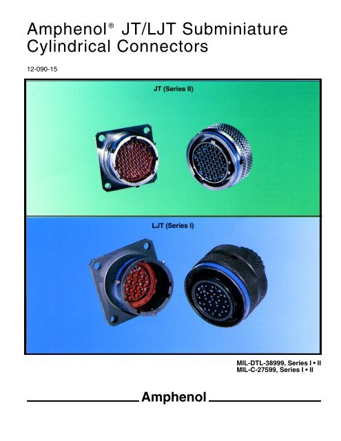
<strong>Amphenol</strong> <strong>JT</strong>/L<strong>JT</strong> <strong>Subminiature</strong><br />
<strong>Cylindrical</strong> Connectors<br />
12-090-15<br />
<strong>Amphenol</strong><br />
MIL-DTL-38999, Series I • II<br />
MIL-C-27599, Series I II
Table of Contents<br />
Description Page<br />
<strong>Amphenol</strong> ® <strong>JT</strong>/L<strong>JT</strong> General Information. . . . . . . . . . . . . . . . . . . . . . . . . . . 1<br />
<strong>JT</strong>/L<strong>JT</strong> - The subminiature cylindrical for every application . . . . . . . . . . . . . . . . . 2<br />
<strong>JT</strong>/L<strong>JT</strong> - Specifications . . . . . . . . . . . . . . . . . . . . . . . . . . . . . . . . . . . 3<br />
<strong>JT</strong>/L<strong>JT</strong> - Insert availability and identification; alternate positioning . . . . . . . . . . . . 4, 5<br />
<strong>JT</strong>/L<strong>JT</strong> - Insert availability and identification . . . . . . . . . . . . . . . . . . . . . . . . 6<br />
<strong>JT</strong>/L<strong>JT</strong> - Insert arrangements . . . . . . . . . . . . . . . . . . . . . . . . . . . . . . 7 – 11<br />
<strong>JT</strong> - Crimp, <strong>JT</strong>00R (MS27472) wall mounting receptacle . . . . . . . . . . . . . . . . . . 12<br />
<strong>JT</strong> - Crimp, <strong>JT</strong>PQ00R (MS27497), wall mounting receptacle, back panel mounting . . . . 13<br />
<strong>JT</strong> - Crimp, <strong>JT</strong>01R, line receptacle . . . . . . . . . . . . . . . . . . . . . . . . . . . . . 14<br />
<strong>JT</strong> - Crimp, <strong>JT</strong>02R (MS27499), box mounting receptacle. . . . . . . . . . . . . . . . . . 15<br />
<strong>JT</strong> - Crimp, <strong>JT</strong>P02R (MS27508), box mounting recept., back panel mounting . . . . . . . 16<br />
<strong>JT</strong> - Crimp, <strong>JT</strong>06R (MS27473), straight plug . . . . . . . . . . . . . . . . . . . . . . . . 17<br />
<strong>JT</strong> - Crimp, <strong>JT</strong>G06R (MS27484), straight plug with grounding fingers . . . . . . . . . . . 18<br />
<strong>JT</strong> - Crimp, <strong>JT</strong>07R (MS27474), jam nut receptacle . . . . . . . . . . . . . . . . . . . . . 19<br />
<strong>JT</strong> - Crimp, <strong>JT</strong>L07R, jam nut receptacle, miniature jam nut mounting dimensions . . . . . 20<br />
<strong>JT</strong> - Crimp, <strong>JT</strong>08R (MS27500), 90° plug . . . . . . . . . . . . . . . . . . . . . . . . . . 21<br />
<strong>JT</strong> - Hermetic, <strong>JT</strong>00 (MS27475), wall mounting receptacle . . . . . . . . . . . . . . . . . 22<br />
<strong>JT</strong> - Hermetic, <strong>JT</strong>02 (MS27476), box mounting receptacle . . . . . . . . . . . . . . . . . 23<br />
<strong>JT</strong> - Hermetic, <strong>JT</strong>07 (MS27477), jam nut receptacle . . . . . . . . . . . . . . . . . . . . 24<br />
<strong>JT</strong> - Hermetic, <strong>JT</strong>I (MS27478), solder mounting receptacle. . . . . . . . . . . . . . . . . 25<br />
<strong>JT</strong> - Accessories, plug protection cap . . . . . . . . . . . . . . . . . . . . . . . . . . . . 26<br />
<strong>JT</strong> - Accessories, receptacle protection cap . . . . . . . . . . . . . . . . . . . . . . . . 27<br />
<strong>JT</strong> - Accessories, strain relief (crimp type) . . . . . . . . . . . . . . . . . . . . . . . . . 28<br />
L<strong>JT</strong> - Crimp, L<strong>JT</strong>00R (MS27466) wall mounting receptacle . . . . . . . . . . . . . . . . 29<br />
L<strong>JT</strong> - Crimp, L<strong>JT</strong>PQ00R (MS27656) wall mounting receptacle, back panel mounting . . . 30<br />
L<strong>JT</strong> - Crimp, L<strong>JT</strong>01R line receptacle . . . . . . . . . . . . . . . . . . . . . . . . . . . . 31<br />
L<strong>JT</strong> - Crimp, L<strong>JT</strong>02R (MS27496) box mounting receptacle. . . . . . . . . . . . . . . . . 32<br />
L<strong>JT</strong> - Crimp, L<strong>JT</strong>P02R (MS27505) box mounting receptacle, back panel mounting . . . . 32<br />
L<strong>JT</strong> - Crimp, L<strong>JT</strong>06R (MS27467) straight plug . . . . . . . . . . . . . . . . . . . . . . . 33<br />
L<strong>JT</strong> - Crimp, L<strong>JT</strong>07R (MS27468) jam nut receptacle . . . . . . . . . . . . . . . . . . . . 34<br />
L<strong>JT</strong> - Hermetic, L<strong>JT</strong>00 (MS27469) wall mounting receptacle . . . . . . . . . . . . . . . . 35<br />
L<strong>JT</strong> - Hermetic, L<strong>JT</strong>07 (MS27470) jam nut receptacle . . . . . . . . . . . . . . . . . . . 36<br />
L<strong>JT</strong> - Hermetic, L<strong>JT</strong>I (MS27471) solder mounting receptacle. . . . . . . . . . . . . . . . 37<br />
L<strong>JT</strong> - Accessories, plug protection cap . . . . . . . . . . . . . . . . . . . . . . . . . . . 38<br />
L<strong>JT</strong> - Accessories, receptacle protection cap . . . . . . . . . . . . . . . . . . . . . . . . 39<br />
L<strong>JT</strong> - Accessories, strain relief (solder type) . . . . . . . . . . . . . . . . . . . . . . . . 40<br />
<strong>JT</strong>/L<strong>JT</strong> - Crimp contacts, printed circuit board, wire wrap contacts (sockets) . . . . . . . . 41<br />
L<strong>JT</strong> - Printed circuit board, wire wrap contacts (sockets) . . . . . . . . . . . . . . . . . . 42<br />
<strong>JT</strong>/L<strong>JT</strong> - Printed circuit board, wire wrap contacts (pins) . . . . . . . . . . . . . . . . . . 43<br />
<strong>JT</strong>/L<strong>JT</strong> - Accessories, header assembly for flex print or PC board connectors . . . . . . . 44<br />
<strong>JT</strong>/L<strong>JT</strong> - Thermocouple contacts, plastic protection caps, sealing plugs . . . . . . . . . . 45<br />
<strong>JT</strong>/L<strong>JT</strong> - Accessories, M85049 strain reliefs, adapters, backshells,<br />
“ABK” heat shrinkable backshells . . . . . . . . . . . . . . . . . . . . . . . . . 46<br />
<strong>JT</strong>/L<strong>JT</strong> - Application tools . . . . . . . . . . . . . . . . . . . . . . . . . . . . . . . . . . 47<br />
<strong>JT</strong>/L<strong>JT</strong> - Solder contact connectors . . . . . . . . . . . . . . . . . . . . . . . . . . . . . 48<br />
<strong>JT</strong>/L<strong>JT</strong> - How to Order. . . . . . . . . . . . . . . . . . . . . . . . . . . . . . . . . . . . 49<br />
Specials - <strong>JT</strong>/L<strong>JT</strong> Connectors Types - Breakaway/Quick Disconnect, Filter, Aquacon . . . 50<br />
Specials - <strong>JT</strong>/L<strong>JT</strong> Ground Plane Connectors . . . . . . . . . . . . . . . . . . . . . . . . 51<br />
Sales Office and Distributor Listing<br />
NOTE:<br />
The connector products in this brochure were formerly known as Bendix ® products. These products are<br />
now manufactured and sold under the <strong>Amphenol</strong> ® brand name. The name “<strong>Amphenol</strong>” will replace the<br />
name “Bendix” on products and literature in the future.<br />
<strong>Amphenol</strong> Aerospace is a Certified ISO 90001 Manufacturer<br />
MS Number Page<br />
MS20047 . . . . . . . . . . . . . . . . 39<br />
MS20048 . . . . . . . . . . . . . . . . 38<br />
MS27352 . . . . . . . . . . . . . . . . 26<br />
MS27353 . . . . . . . . . . . . . . . . 27<br />
MS27466 . . . . . . . . . . . . . . . . 29<br />
MS27467 . . . . . . . . . . . . . . . . 33<br />
MS27468 . . . . . . . . . . . . . . . . 34<br />
MS27469 . . . . . . . . . . . . . . . . 35<br />
MS27470 . . . . . . . . . . . . . . . . 36<br />
MS27471 . . . . . . . . . . . . . . . . 37<br />
MS27472 . . . . . . . . . . . . . . . . 12<br />
MS27473 . . . . . . . . . . . . . . . . 17<br />
MS27474 . . . . . . . . . . . . . . . . 19<br />
MS27475 . . . . . . . . . . . . . . . . 22<br />
MS27476 . . . . . . . . . . . . . . . . 23<br />
MS27477 . . . . . . . . . . . . . . . . 24<br />
MS27478 . . . . . . . . . . . . . . . . 25<br />
MS27479 . . . . . . . . . . . . . . . . 12<br />
MS27482 . . . . . . . . . . . . . . . . 22<br />
MS27483 . . . . . . . . . . . . . . . . 24<br />
MS27484 . . . . . . . . . . . . . . . . 18<br />
MS27488 . . . . . . . . . . . . . . . . 44<br />
MS27496 . . . . . . . . . . . . . . . . 32<br />
MS27497 . . . . . . . . . . . . . . . . 13<br />
MS27499 . . . . . . . . . . . . . . . . 15<br />
MS27500 . . . . . . . . . . . . . . . . 21<br />
MS27501 . . . . . . . . . . . . . . . . 38<br />
MS27502 . . . . . . . . . . . . . . . . 39<br />
MS27503 . . . . . . . . . . . . . . . . 25<br />
MS27505 . . . . . . . . . . . . . . . . 32<br />
MS27506-2 . . . . . . . . . . . . . . 28<br />
MS27508 . . . . . . . . . . . . . . . . 16<br />
MS27510 . . . . . . . . . . . . . . . . 26<br />
MS27511 . . . . . . . . . . . . . . . . 27<br />
MS27656 . . . . . . . . . . . . . . . . 30
®<br />
<strong>Amphenol</strong> <strong>JT</strong>/L<strong>JT</strong><br />
high reliability and high contact density<br />
with maximum weight and space savings<br />
<strong>Amphenol</strong> ® <strong>JT</strong> Connector<br />
<strong>Amphenol</strong> ® L<strong>JT</strong> Connector<br />
1<br />
<strong>Amphenol</strong> ® L<strong>JT</strong> and <strong>JT</strong> Series subminiature<br />
cylindrical connectors are qualified to MIL-DTL-<br />
38999*, Series I and II respectively. These connectors<br />
were developed to meet the needs of<br />
the aerospace industries, and provided the<br />
impetus for development of the MIL-C-38999<br />
specifications, which recently were superseded<br />
by MIL-DTL-38999. Meeting or exceeding MIL-<br />
DTL-38999 requirements, <strong>Amphenol</strong> ® <strong>JT</strong>/L<strong>JT</strong><br />
connectors feature:<br />
Lightweight, Space Saving Design<br />
Contact Protection - 100% scoop-proof L<strong>JT</strong><br />
design prevents bent pins and short circuits during<br />
mating<br />
Quick Positive Coupling - 3 point bayonet lock<br />
system<br />
Mismating Eliminated - with 5 key/keyway<br />
design<br />
Error Proof Alternate Positioning - insured by<br />
different key/keyway locations<br />
EMI Shielding - grounding fingers standard in<br />
L<strong>JT</strong> Series; optional in <strong>JT</strong> Series<br />
Nine Shell Sizes and a Variety of Shell Styles<br />
Contact Options - size 8, 10, 12, 16, 20, 22M<br />
and 22D Crimp, Solder, PCB, Wire wrap, Coax,<br />
Twinax, Triax, Thermocouple, Fiber Optic and Filter<br />
Fixed Solder Contacts - per MIL-C-27599 (see<br />
page 45)<br />
Hermetic - air leakage limited to 1 X 10⁻⁷ cm3 per<br />
second optional<br />
Inventory Support Commonality - uses standard<br />
MIL-C-38999 contacts, insert arrangements<br />
and application tools.<br />
Where proof of high reliability and lot control is<br />
required, MS approved equivalents to most proprietary<br />
<strong>JT</strong> and L<strong>JT</strong> connectors are available.<br />
For additional information on <strong>Amphenol</strong> ® <strong>JT</strong>/L<strong>JT</strong> connectors,<br />
or for special application requirements, contact your<br />
local sales office or<br />
<strong>Amphenol</strong> Corporation<br />
<strong>Amphenol</strong> Aerospace<br />
40 – 60 Delaware Avenue<br />
Sidney, New York 13838-1395<br />
Telephone: 607-563-5011<br />
Fax: 607-563-5157<br />
www.amphenol-aerospace.com<br />
* MIL-DTL-38999 Series I supersedes MIL-C-38999 Series I.<br />
MIL-DTL-38999 Series II supersedes MIL-C-38999 Series II.
<strong>JT</strong>/L<strong>JT</strong><br />
the subminiature cylindrical<br />
for every application<br />
Wall Mounting Receptacle<br />
Box Mounting Receptacle<br />
Straight Plug<br />
Jam Nut Receptacle<br />
90° Plug<br />
Solder Mounting Receptacle<br />
Wall Mounting Receptacle<br />
Line Receptacle<br />
Jam Nut Receptacle<br />
Straight Plug<br />
Solder Mounting Receptacle<br />
2<br />
Components<br />
Shell components are impact extruded or machined<br />
bar stock aluminum. Standard plating on shell components<br />
is cadmium over nickel. Many finishes are<br />
optional (see “Specifications” page 3). Hermetic<br />
seal receptacles are available in carbon steel or<br />
stainless steel shells. Dependable 5 key/keyway<br />
polarization with bayonet lock coupling is incorporated<br />
to aid and assure positive mating.<br />
Insert material is a rigid dielectric with excellent<br />
electrical characteristics, providing durable protection<br />
for molded-in solder type contacts. Contrasting<br />
letter or number designations are used on insert<br />
faces.<br />
A fluorinated silicone interfacial seal wafer is featured<br />
on the mating face of “crimp type pin” inserts.<br />
This assures complete electrical isolation of pins<br />
when connector halves are mated. In addition, a<br />
main joint gasket is installed in the receptacle for<br />
moisture sealing between connector halves. Both<br />
features are also available for hermetic receptacles.<br />
Contacts<br />
Maximum design flexibility is built into the <strong>JT</strong>/L<strong>JT</strong><br />
Series, with a minimum of 2 to a maximum of 128<br />
circuits per connector in a wide variety of contact<br />
arrangements. Contacts are available in sizes 8,<br />
10, 12, 16, 20, 22, 22D and 22M with standard 50<br />
micro inch minimum gold plating (100 micro inches<br />
optional). All socket contacts are probe proof.<br />
Crimp type rear removable contacts are featured in<br />
<strong>JT</strong>-R and L<strong>JT</strong>-R connectors. Solder termination<br />
contacts are also available, as well as PCB, wire<br />
wrap, thermocouple, fiber optic, coaxial, triaxial and<br />
twinax contact options.<br />
Optional Features<br />
High temperature capability of 392°F is available<br />
only in <strong>JT</strong>S or L<strong>JT</strong>S crimp type connectors. High<br />
temperature versions feature gold plated contacts,<br />
high temperature shell plating, stainless steel coupling<br />
nut spring, and epoxy inserts/fluorinated silicone<br />
grommet combination. Standard temperature<br />
capability for both solder and crimp is 302°F.<br />
The <strong>JT</strong>N or L<strong>JT</strong>N type connectors are available for<br />
N2O4 resistance provided they are mated, and ungrommeted<br />
rear faces are suitably protected.<br />
For complete listing and definition of connector<br />
types, shell styles and service classes, see How to<br />
Order, page 49.
<strong>JT</strong>/L<strong>JT</strong><br />
specifications<br />
Contact<br />
Size<br />
Test Current<br />
Maximum<br />
Maximum<br />
Millivolt Drop<br />
Solder &<br />
Millivolt Drop<br />
Crimp Hermetic Crimp* Solder* Hermetic*<br />
* When tested using silver plated wire.<br />
CONTACT RATING<br />
** Please note that the establishment of electrical safety factors is left entirely in the designer’s hands, since he is in the best position to know what peak voltage, switching<br />
surges, transients, etc. can be expected in a particular circuit.<br />
3<br />
Contact<br />
Size<br />
Crimp Well Data Solder Well Data<br />
Well<br />
Diameter<br />
Nominal<br />
Well Depth<br />
Well<br />
Diameter<br />
Nominal<br />
Well Depth<br />
22M 3 2 45 20 60 22M .028 ±.001 .141 .029 +.004<br />
–.000<br />
22D 5 3 73 85 22D .0345 ±.0010 .141<br />
22 5 3 73 20 85 22 .0365 ±.0010 .141 .036 +.004<br />
–.000<br />
.094<br />
20 7.5 5 55 20 60 20 .047 ±.001 .209 .044 +.004<br />
–.004<br />
.125<br />
16 13 10 49 20 85 16 .067 ±.001 .209 .078 +.000<br />
–.004<br />
.141<br />
12 23 17 42 20 85 12 .100 ±.002 .209 .116 +.004<br />
–.002<br />
.141<br />
10 (Power) 33 NA 33 NA NA 10 (Power) .137 ±.002 .355 NA NA<br />
Service<br />
Rating<br />
Suggested Operating Voltage<br />
(Sea Level)<br />
AC (RMS) DC<br />
SERVICE RATING**<br />
Test Voltage<br />
(Sea Level)<br />
Test Voltage<br />
50,000 Ft.<br />
Test Voltage<br />
70,000 Ft.<br />
Test Voltage<br />
110,000 Ft.<br />
M 400 500 1300 VRMS 550 VRMS 350 VRMS 200 VRMS<br />
N 300 450 1000 VRMS 400 VRMS 260 VRMS 200 VRMS<br />
I 600 850 1800 VRMS 600 VRMS 400 VRMS 200 VRMS<br />
II 900 1250 2300 VRMS 800 VRMS 500 VRMS 200 VRMS<br />
Finish<br />
FINISH DATA<br />
Aluminum Shell Components Non-Hermetic<br />
Suffix<br />
Military Proprietary<br />
Indicated Finish Standard for<br />
<strong>JT</strong> Types Listed Below<br />
Indicated Finish Standard for<br />
L<strong>JT</strong> Types Listed Below<br />
Cadmium Plated Nickel Base MS (A) – <strong>JT</strong>/<strong>JT</strong>G/<strong>JT</strong>L/<strong>JT</strong>P L<strong>JT</strong>/L<strong>JT</strong>P<br />
Anodic Coating (Alumilite) MS (C) (005) <strong>JT</strong>S/<strong>JT</strong>PS/<strong>JT</strong>LS L<strong>JT</strong>PS/L<strong>JT</strong>S<br />
Chromate Treated (Iridite 14-2) (011) <strong>JT</strong>N/<strong>JT</strong>PN/<strong>JT</strong>LN L<strong>JT</strong>N/L<strong>JT</strong>PN<br />
Olive Drab Cadmium Plate Nickel Base MS (B) (014)<br />
Electroless Nickel MS (F) (023)<br />
Material/Finish<br />
Carbon Steel Shell<br />
Tin Plated Shell and Contacts<br />
Carbon Steel Shell<br />
Tin Plated Shell and Gold Plated Contacts<br />
Stainless Steel Shell<br />
Gold Plated Contacts<br />
Hermetic Connectors<br />
Suffix<br />
Military Proprietary<br />
MS (D)<br />
MS (E) (162)<br />
Indicated Finish Standard for<br />
<strong>JT</strong> Types Listed Below<br />
<strong>JT</strong>( )H/<strong>JT</strong>( )Y<br />
<strong>JT</strong>L( )H/<strong>JT</strong>L( )Y<br />
<strong>JT</strong>S( )Y<br />
<strong>JT</strong>LS( )Y<br />
Indicated Finish Standard for<br />
L<strong>JT</strong> Types Listed Below<br />
L<strong>JT</strong>( )Y/L<strong>JT</strong>( )H<br />
L<strong>JT</strong>S( )Y
<strong>JT</strong>/L<strong>JT</strong><br />
insert availability and identification,<br />
alternate positioning<br />
Hermetics<br />
Total<br />
Contact Size<br />
Class Class Service Con-<br />
<strong>JT</strong> L<strong>JT</strong> Solder Crimp H Y* Rating tacts 22D 22M 22 20 16 12<br />
8-2 P<br />
M 2 2<br />
8-3<br />
9-3<br />
X<br />
X<br />
N/A P P<br />
M 3 3<br />
8-6<br />
9-6<br />
X<br />
X<br />
X<br />
X<br />
P<br />
P<br />
P<br />
P<br />
M 6 6<br />
9-7 X<br />
M 7 7<br />
9-22 X<br />
I 2 2<br />
8-35<br />
9-35<br />
X<br />
X<br />
P<br />
P<br />
P<br />
P<br />
M 6 6<br />
8-44<br />
9-44<br />
X<br />
X<br />
P P<br />
M 4 4<br />
8-97 X<br />
M 4 2 2<br />
8-98<br />
9-98<br />
S<br />
X<br />
X<br />
X<br />
P<br />
P<br />
P<br />
P<br />
I 3 3<br />
11-2★ 2 P**<br />
I 2 2<br />
10-4<br />
11-4 X<br />
3<br />
2<br />
I 4 4<br />
10-5<br />
11-5<br />
X<br />
X<br />
X<br />
2<br />
P P<br />
I 5 5<br />
11-6 S<br />
I 6 6<br />
10-13<br />
11-13<br />
X<br />
X<br />
X<br />
X<br />
P<br />
P<br />
P<br />
P<br />
M 13 13<br />
10-35<br />
11-35<br />
X<br />
X<br />
P<br />
P<br />
P<br />
P<br />
M 13 13<br />
10-98<br />
11-98<br />
X<br />
X<br />
X<br />
X<br />
P/S<br />
P<br />
P<br />
P<br />
I 6 6<br />
10-99<br />
11-99<br />
X<br />
P<br />
P P<br />
I 7 7<br />
12-3<br />
13-3<br />
X X<br />
P<br />
P P<br />
II 3 3<br />
12-4<br />
13-4★<br />
X<br />
X<br />
X<br />
X<br />
P<br />
P/S<br />
P<br />
P<br />
I 4 4<br />
12-8<br />
13-8<br />
X<br />
X<br />
X<br />
X<br />
P<br />
P<br />
P/S<br />
P<br />
I 8 8<br />
12-22<br />
13-22 X<br />
X<br />
X<br />
P<br />
P/S<br />
P<br />
P<br />
M 22 22<br />
12-35<br />
13-35<br />
X<br />
X<br />
P<br />
P<br />
P<br />
P<br />
M 22 22<br />
12-98<br />
13-98<br />
X<br />
X<br />
X<br />
X<br />
P/S<br />
P/S<br />
P<br />
P<br />
I 10 10<br />
14-4<br />
15-4<br />
2<br />
3<br />
I 4 4<br />
14-5<br />
15-5★<br />
X<br />
X<br />
X<br />
X<br />
P P<br />
II 5 5<br />
14-15<br />
15-15<br />
X<br />
X<br />
X<br />
X<br />
P/S<br />
P/S<br />
P<br />
P<br />
I 15 14 1<br />
14-18<br />
15-18<br />
X<br />
X<br />
X<br />
X<br />
P/S<br />
P/S<br />
P<br />
P<br />
I 18 18<br />
14-19<br />
15-19<br />
X 3<br />
2<br />
I 19 19<br />
14-35<br />
15-35<br />
X<br />
X<br />
P<br />
P<br />
P<br />
P<br />
M 37 37<br />
14-37<br />
15-37<br />
X<br />
X<br />
X<br />
X<br />
P<br />
P<br />
P<br />
P<br />
M 37 37<br />
14-68<br />
15-68 X<br />
2<br />
3<br />
1 8 8<br />
14-97<br />
15-97 X<br />
2<br />
2<br />
P<br />
P<br />
P<br />
P<br />
I 12 8 4<br />
(P) Pin inserts only (consult Sidney, NY for socket availability)<br />
(S) Socket inserts only (consult Sidney, NY for pin availability)<br />
(2) Not tooled for RP or 02RE<br />
(3) Pin inserts only, not tooled for RP or 02RE (consult Sidney, NY for availability)<br />
4<br />
8<br />
(Coax)<br />
<strong>JT</strong> MASTER KEY/KEYWAY ROTATION<br />
AB ANGLE OF ROTATION (Degrees)<br />
Shell<br />
Size Normal A B C D<br />
8 100° 82° – – 118°<br />
10 100° 86° 72° 128° 114°<br />
12 100° 80° 68° 132° 120°<br />
14 100° 79° 66° 134° 121°<br />
16 100° 82° 70° 130° 118°<br />
18 100° 82° 70° 130° 118°<br />
20 100° 82° 70° 130° 118°<br />
22 100° 85° 74° 126° 115°<br />
24 100° 85° 74° 126° 115°<br />
A plug with a given rotation letter will mate with a receptacle<br />
with the same rotation letter. The AB angle for a given connector<br />
is the same whether it contains pins or sockets. Only the<br />
master key/keyway rotates in the shell, and the insert always<br />
remains in the same position relative to the minor keys.<br />
AB angles shown are viewed from the front face of the connector,<br />
a receptacle is shown below. The angles for the plug are<br />
exactly the same except the direction of rotation is opposite of<br />
that shown for the receptacle.<br />
10° <strong>JT</strong> REF<br />
RELATIVE POSSIBLE POSITION<br />
OF ROTATED MASTER KEYWAY<br />
(front face of receptacle shown)<br />
* Same as H with interfacial seal<br />
** Tooled with special terminal only (consult Sidney, NY for availability of standard<br />
terminal)<br />
★ Ground plane proprietary option available. See page 51 for further information on<br />
ground plane connectors.
<strong>JT</strong>/L<strong>JT</strong><br />
insert availability and identification,<br />
alternate positioning<br />
Hermetics<br />
Total<br />
Contact Size<br />
Class Class Service Con-<br />
8 8<br />
<strong>JT</strong> L<strong>JT</strong> Solder Crimp H Y* Rating tacts 22D 22M 22 20 16 12 (Coax) (Twinax)<br />
17-2 2<br />
M 39 38 1<br />
16-6<br />
17-6<br />
X<br />
X<br />
P<br />
P<br />
P<br />
P<br />
I 6 6<br />
16-8<br />
17-8★<br />
X<br />
X<br />
X<br />
X<br />
P<br />
P<br />
P<br />
P/S<br />
II 8 8<br />
16-13<br />
17-13<br />
2<br />
2<br />
I 13 13<br />
17-22<br />
Coax 4<br />
2<br />
Coax<br />
2<br />
17-25 2<br />
16-26 X X P/S P<br />
17-26 X X P/S P<br />
16-35 X P/S P<br />
17-35 X X P P<br />
16-42 X<br />
17-42 P<br />
16-55 X X P/S P<br />
17-55 X X P<br />
16-99 X X P P<br />
17-99 X X S<br />
18-11 X X P P<br />
19-11★ X X P P<br />
19-18 2<br />
18-28 X X P P<br />
19-28 X P<br />
18-30 X X<br />
19-30 X P<br />
18-32 X X P/S P<br />
19-32 X X P/S P<br />
18-35 X P P<br />
19-35 X P P<br />
18-53 X X<br />
19-53 P<br />
18-66 X X P P<br />
19-66 X P P<br />
19-67 X 3 S<br />
18-68 2<br />
19-68 3<br />
18-96 2<br />
20-1 X P<br />
21-1 X S<br />
20-2 X<br />
21-2 2<br />
20-11 3<br />
21-11★ 2<br />
20-16 X X P P<br />
21-16★ X X P P<br />
21-24 X<br />
21-25 X<br />
21-27 X<br />
20-35 X<br />
21-35 X<br />
20-39 X X P P<br />
21-39 X X<br />
20-41 X X P P<br />
21-41 X X S<br />
(P) Pin inserts only (consult Sidney, NY for socket availability)<br />
(S) Socket inserts only (consult Sidney, NY for pin availability)<br />
(2) Not tooled for RP or 02RE<br />
M 24 22 2<br />
I 26 26<br />
M 55 55<br />
M 42 42<br />
M 55 55<br />
I 23 21 2<br />
II 11 11<br />
M 18 14 4<br />
I 28 26 2<br />
I 30 29 1<br />
I 32 32<br />
M 66 66<br />
M 53 53<br />
M 66 66<br />
M 67 67<br />
I 18 18<br />
I 9 9<br />
M 79 79<br />
M 65 65<br />
I 11 11<br />
II 16 16<br />
I 24 24<br />
I 25 25<br />
I 27 27<br />
M 79 79<br />
I 39 37 2<br />
I 41 41<br />
5<br />
L<strong>JT</strong> MASTER KEY/KEYWAY ROTATION<br />
AB ANGLE OF ROTATION (Degrees)<br />
Shell<br />
Size Normal A B C D<br />
9 95° 77° – – 113°<br />
11 95° 81° 67° 123° 109°<br />
13 95° 75° 63° 127° 115°<br />
15 95° 74° 61° 129° 116°<br />
17 95° 77° 65° 125° 113°<br />
19 95° 77° 65° 125° 113°<br />
21 95° 77° 65° 125° 113°<br />
23 95° 80° 69° 121° 110°<br />
25 95° 80° 69° 121° 110°<br />
A plug with a given rotation letter will mate with a receptacle<br />
with the same rotation letter. The AB angle for a given connector<br />
is the same whether it contains pins or sockets. Only the<br />
master key/keyway rotates in the shell, and the insert always<br />
remains in the same position relative to the minor keys.<br />
AB angles shown are viewed from the front face of the connector,<br />
a receptacle is shown below. The angles for the plug are<br />
exactly the same except the direction of rotation is opposite of<br />
that shown for the receptacle.<br />
5° L<strong>JT</strong> REF<br />
RELATIVE POSSIBLE POSITION<br />
OF ROTATED MASTER KEYWAY<br />
(front face of receptacle shown)<br />
(3) Pin inserts only, not tooled for RP or 02RE (consult Sidney, NY for availability)<br />
* Same as H with interfacial seal<br />
★ Ground plane proprietary option available. See page 51 for further information on<br />
ground plane connectors.
<strong>JT</strong>/L<strong>JT</strong><br />
insert availability and identification<br />
<strong>JT</strong> L<strong>JT</strong> Solder Crimp<br />
21-75★ 2<br />
21-79 2<br />
22-1 X<br />
23-1 X<br />
22-2 X X P P<br />
23-2 X X P P<br />
23-5 X<br />
23-6★ P<br />
22-14 2<br />
23-14 2<br />
22-21 X X P P<br />
23-21★ X X P P<br />
22-32 X X P<br />
23-32 X P<br />
23-34 X<br />
22-35 X<br />
23-35 X<br />
23-36 X<br />
22-53 P<br />
23-53 X X P/S<br />
22-55 X X P P<br />
23-55 3<br />
23-97 X<br />
23-99 X<br />
24-1 X<br />
25-1 X<br />
24-2 X<br />
25-2 X<br />
24-4 X P P<br />
25-4 X<br />
25-7 2<br />
25-11 2<br />
24-19 2<br />
25-19★ 2<br />
25-20 2<br />
24-24 X P P<br />
25-24★ X<br />
24-29 X<br />
25-29★ X X<br />
24-35 X<br />
25-35 X<br />
24-37 2<br />
25-37★ 2<br />
24-43 3<br />
25-43 X 2 P P<br />
25-46 2<br />
24-61 X X P P<br />
25-61 X X P P<br />
Hermetics<br />
Total<br />
Contact Size<br />
Class Class Service Con-<br />
H Y* Rating tacts 22D 22M 22 20 16 12<br />
N 4<br />
II 19 17<br />
M 100 100<br />
M 85 85<br />
6<br />
8<br />
(Coax)<br />
8††<br />
(Twinax)<br />
M 5 5<br />
M 6 6<br />
I 14 14<br />
II 21 21<br />
I 32 32<br />
I 34 34<br />
M 100 100<br />
I 36 36<br />
I 53 53<br />
I 55 55<br />
II 16 16<br />
II 11 11<br />
M 128 128<br />
M 100 100<br />
I 56 48 8<br />
M 99 97 2<br />
10<br />
(Power)<br />
N 11 2 9<br />
I 19 19<br />
N 30 10 13** 3 4<br />
I 24 12 12<br />
I 29 29<br />
M 128 128<br />
I 37 37<br />
I 43 23 20<br />
I 46 40 4 2†<br />
I 61 61<br />
(P) Pin inserts only (consult Sidney, NY for socket availability)<br />
(S) Socket inserts only (consult Sidney, NY for pin availability)<br />
(2) Not tooled for RP or 02RE<br />
(3) Pin inserts only, not tooled for RP or 02RE (consult Sidney, NY for availability)<br />
* Same as H with interfacial seal<br />
** Two size 16 contacts dedicated to fiber optics. Consult Sidney, NY or catalog<br />
section 12-352 for fiber optic contact information.<br />
† For RG180/U and RG195/U cables only (consult Sidney, NY for other cable<br />
applications)<br />
(See Note 4)<br />
(See Note 5)<br />
12<br />
Coax<br />
†† Size 8 Coax and Twinax are interchangeable<br />
(4) MS connector 21-75 is supplied with four size 8 twinax contacts. Proprietary<br />
connector 21-75 is supplied with four size 8 coax contacts.<br />
(5) MS connector 21-79 has provision for two size 8 coax contacts. Coax contacts<br />
are not supplied unless specified by customer.<br />
★ Ground plane proprietary option available. See page 51 for further information<br />
on ground plane connectors.
<strong>JT</strong>/L<strong>JT</strong><br />
insert arrangements<br />
front face of pin inserts illustrated<br />
7<br />
black arrangements – <strong>JT</strong> or L<strong>JT</strong><br />
green arrangements – <strong>JT</strong> only<br />
blue arrangements – L<strong>JT</strong> only<br />
Insert Arrangement (<strong>JT</strong>) 8-2 8-3 8-6 8-35 8-44 8-97 8-98<br />
Insert Arrangement (L<strong>JT</strong>) 9-3 9-6 9-7 9-22 9-35 9-44 9-98<br />
Service Rating M M M M I M M M I<br />
Number of Contacts 2 3 6 7 2 6 4 2 2 3<br />
Contact Size 20 20 22M 22M 20 22D 22 22M 20 20<br />
Insert Arrangement (<strong>JT</strong>) 10-4 10-5 10-13 10-35 10-98 10-99<br />
Insert Arrangement (L<strong>JT</strong>) 11-2 11-4 11-5 11-6 11-13 11-35 11-98 11-99<br />
Service Rating I I I I M M I I<br />
Number of Contacts 2 4 5 6 13 13 6 7<br />
Contact Size 16 20 20 20 22M 22D 20 20<br />
Insert Arrangement (<strong>JT</strong>) 12-3 12-4 12-8 12-22 12-35 12-98 14-4 14-5<br />
Insert Arrangement (L<strong>JT</strong>) 13-3 13-4 13-8 13-22 13-35 13-98 15-4 15-5<br />
Service Rating II I I M M I I II<br />
Number of Contacts 3 4 8 22 22 10 4 5<br />
Contact Size 16 16 20 22M 22D 20 12 16<br />
Insert Arrangement (<strong>JT</strong>) 14-15 14-18 14-19 14-35 14-37 14-68 14-97<br />
Insert Arrangement (L<strong>JT</strong>) 15-15 15-18 15-19 15-35 15-37 15-68 15-97<br />
Service Rating I I I M M I I<br />
Number of Contacts 14 1 18 19 37 37 8 8 4<br />
Contact Size 20 16 20 20 22D 22M 16 20 16<br />
CONTACT LEGEND 8 10 12 16 20 22 22M 22D
<strong>JT</strong>/L<strong>JT</strong><br />
insert arrangements<br />
front face of pin inserts illustrated<br />
8<br />
black arrangements – <strong>JT</strong> or L<strong>JT</strong><br />
green arrangements – <strong>JT</strong> only<br />
blue arrangements – L<strong>JT</strong> only<br />
Insert Arrangement (<strong>JT</strong>) 16-6 16-8 16-13 16-26<br />
Insert Arrangement (L<strong>JT</strong>) 17-2 17-6 17-8 17-13 17-22 17-25 17-26<br />
Service Rating M I II I Coax M I<br />
Number of Contacts 38 1 6 8 13 2 2 22 2 26<br />
Contact Size 22D 8 Twinax 12 16 16 12 Coax 8 Coax 22D 8 Coax 20<br />
Insert Arrangement (<strong>JT</strong>) 16-35 16-42 16-55 16-99 18-11<br />
Insert Arrangement (L<strong>JT</strong>) 17-35 17-42 17-55 17-99 19-11 19-18<br />
Service Rating M M M I II M<br />
Number of Contacts 55 42 55 21 2 11 14 4<br />
Contact Size 22D 22 22M 20 16 16 22D 8 Twinax<br />
Insert Arrangement (<strong>JT</strong>) 18-28 18-30 18-32 18-35 18-53 18-66<br />
Insert Arrangement (L<strong>JT</strong>) 19-28 19-30 19-32 19-35 19-53 19-66<br />
Service Rating I I I M M M<br />
Number of Contacts 26 2 29 1 32 66 53 66<br />
Contact Size 20 16 20 16 20 22D 22 22M<br />
Insert Arrangement (<strong>JT</strong>) 18-68 18-96 20-1 20-2<br />
Insert Arrangement (L<strong>JT</strong>) 19-67 19-68 21-1 21-2<br />
Service Rating M I I M M<br />
Number of Contacts 67 18 9 79 65<br />
Contact Size 22M 16 12 22M 22<br />
CONTACT LEGEND 8 10 12 16 20 22 22M 22D
<strong>JT</strong>/L<strong>JT</strong><br />
insert arrangements<br />
front face of pin inserts illustrated<br />
9<br />
black arrangements – <strong>JT</strong> or L<strong>JT</strong><br />
green arrangements – <strong>JT</strong> only<br />
blue arrangements – L<strong>JT</strong> only<br />
Insert Arrangement (<strong>JT</strong>) 20-11 20-16<br />
Insert Arrangement (L<strong>JT</strong>) 21-11 21-16 21-24 21-25 21-27<br />
Service Rating I II I I I<br />
Number of Contacts 11 16 24 25 27<br />
Contact Size 12 16 20 20 20<br />
Insert Arrangement (<strong>JT</strong>) 20-35 20-39 20-41<br />
Insert Arrangement (L<strong>JT</strong>) 21-35 21-39 21-41 21-75 21-79<br />
Service Rating M I I N II<br />
Number of Contacts 79 37 2 41 4 17 (See Note)<br />
Contact Size 22D 20 16 20 (See Note) 22D<br />
Insert Arrangement 22-1 22-2 22-14<br />
Insert Arrangement (L<strong>JT</strong>) 23-1 23-2 23-5 23-6 23-14<br />
Service Rating M M M M I<br />
Number of Contacts 100 85 5 6 14<br />
Contact Size 22M 22 8 Twinax 8 Twinax 12<br />
Note: MS connector 21-75 is supplied with four size 8 twinax contacts.<br />
Proprietary connector 21-75 is supplied with four size 8 coax contacts.<br />
MS connector 21-79 has provision for two size 8 coax contacts.<br />
Coax contacts are not supplied unless specified by customer. CONTACT LEGEND 8 10 12 16 20 22 22M 22D
<strong>JT</strong>/L<strong>JT</strong><br />
insert arrangements<br />
front face of pin inserts illustrated<br />
10<br />
black arrangements – <strong>JT</strong> or L<strong>JT</strong><br />
green arrangements – <strong>JT</strong> only<br />
blue arrangements – L<strong>JT</strong> only<br />
Insert Arrangement (<strong>JT</strong>) 22-21 22-32 22-35<br />
Insert Arrangement (L<strong>JT</strong>) 23-21 23-32 23-34 23-35<br />
Service Rating II I I M<br />
Number of Contacts 21 32 34 100<br />
Contact Size 16 20 20 22D<br />
Insert Arrangement (<strong>JT</strong>) 22-53 22-55<br />
Insert Arrangement (L<strong>JT</strong>) 23-36 23-53 23-55 23-97<br />
Service Rating I I I II<br />
Number of Contacts 36 53 55 16<br />
Contact Size 20 20 20 16<br />
Insert Arrangement (<strong>JT</strong>) 24-1 24-2 24-4<br />
Insert Arrangement (L<strong>JT</strong>) 23-99 25-1 25-2 25-4<br />
Service Rating II M M I<br />
Number of Contacts 11 128 100 48 8<br />
Contact Size 16 22M 22 20 16<br />
CONTACT LEGEND 8 10 12 16 20 22 22M 22D
<strong>JT</strong>/L<strong>JT</strong><br />
insert arrangements<br />
front face of pin inserts illustrated<br />
11<br />
black arrangements – <strong>JT</strong> or L<strong>JT</strong><br />
green arrangements – <strong>JT</strong> only<br />
blue arrangements – L<strong>JT</strong> only<br />
Insert Arrangement (<strong>JT</strong>) 24-19<br />
Insert Arrangement (L<strong>JT</strong>) 25-7 25-11 25-19 25-20<br />
Service Rating M N I N<br />
Number of Contacts 97 2 2 9 19 10 13 3 4<br />
Contact Size 22D 8 Twinax 20 10 12 20 16 8 Twinax 12 Coax<br />
(Locations U and Y - Dedicated<br />
to Fiber Optics)<br />
Insert Arrangement (<strong>JT</strong>) 24-24 24-29 24-35 24-37<br />
Insert Arrangement (L<strong>JT</strong>) 25-24 25-29 25-35 25-37<br />
Service Rating I I M I<br />
Number of Contacts 12 12 29 128 37<br />
Contact Size 16 12 16 22D 16<br />
Insert Arrangement (<strong>JT</strong>) 24-43 24-61<br />
Insert Arrangement (L<strong>JT</strong>) 25-43 25-46 25-61<br />
Service Rating I I I<br />
Number of Contacts 23 20 40 4 2 61<br />
Contact Size 20 16 20 16 8 Coax† 20<br />
† Coax contacts for RG180 or RG195 cable.<br />
CONTACT LEGEND 8 10 12 16 20 22 22M 22D
<strong>JT</strong>00R (MS27472) — crimp<br />
wall mounting receptacle<br />
� ������������� ����������<br />
�� �������������� ����������<br />
��� ��������������<br />
12<br />
� ������������� ����������<br />
�� �������������� ����������<br />
��� ��������������<br />
� ������������� ���������� � ������������� ����<br />
�� �������������� �� �������������� ����<br />
��� �������������� ��� �������������� ����<br />
+ .005 DIA M<br />
* To complete order number see page 49.<br />
** High temperature version; to complete order number see page 49.<br />
*** Clear iridite finish (gold color), N2O4 resistant; to complete order number see page 49.<br />
Shell<br />
Size<br />
F<br />
Dia.<br />
+.010<br />
–.025<br />
F 1<br />
Dia.<br />
±.010<br />
All dimensions for reference only.<br />
L<br />
Max.<br />
L 1<br />
Max.<br />
L 2<br />
Max.<br />
L 3<br />
Max.<br />
N<br />
+.001<br />
–.005<br />
R<br />
(TP)<br />
S<br />
±.016<br />
T<br />
±.005<br />
V Thread<br />
UNEF<br />
Class 2A<br />
(Plated)<br />
8 .125 .444 1.094 .609 .547 .500 .473 .594 .812 .120 .4375-28 .812 .625 .578<br />
10 .188 .558 1.094 .609 .547 .500 .590 .719 .938 .120 .5625-24 .875 .750 .703<br />
12 .312 .683 1.094 .609 .547 .500 .750 .812 1.031 .120 .6875-24 1.000 .875 .828<br />
14 .375 .808 1.344 .609 .547 .500 .875 .906 1.125 .120 .8125-20 1.125 1.000 .953<br />
16 .500 .909 1.344 .609 .547 .500 1.000 .969 1.219 .120 .9375-20 1.188 1.125 1.078<br />
18 .625 1.034 1.344 .609 .547 .500 1.125 1.062 1.312 .120 1.0625-18 1.438 1.250 1.203<br />
20 .625 1.159 1.344 .609 .547 .500 1.250 1.156 1.438 .120 1.1875-18 1.438 1.375 1.328<br />
22 .750 1.284 1.469 .609 .547 .500 1.375 1.250 1.562 .120 1.3125-18 1.625 1.500 1.453<br />
24 .800 1.409 1.469 .688 .547 .500 1.500 1.375 1.688 .147 1.4375-18 1.719 1.625 1.578<br />
KK<br />
Max.<br />
KK 1<br />
Dia.<br />
Max.<br />
KK 2<br />
Dia.<br />
Max.
<strong>JT</strong>PQ00R (MS27497) — crimp<br />
wall mounting receptacle (back panel mounting)<br />
+ .005 DIA M<br />
* To complete order number see page 49.<br />
** High temperature version; to complete order number see page 49.<br />
Shell<br />
Size<br />
F<br />
Dia.<br />
+.010<br />
–.025<br />
F 1<br />
Dia.<br />
±.010<br />
All dimensions for reference only.<br />
L<br />
Max.<br />
L 1<br />
Max.<br />
N<br />
Dia.<br />
+.001<br />
–.005<br />
� ��������������� ���������� � ��������������� ����������<br />
�� ����������������<br />
� ��������������� ���������� � ��������������� ����<br />
P<br />
Max.<br />
Panel<br />
Thickness<br />
R<br />
(TP)<br />
S<br />
±.016<br />
13<br />
T<br />
Dia.<br />
±.005<br />
V Thread<br />
UNEF<br />
Class 2A<br />
(Plated)<br />
8 .125 .444 1.140 .468 .473 .142 .594 .812 .120 .4375-28 .516 .781 .625 .578 .563<br />
10 .188 .558 1.140 .468 .590 .142 .719 .938 .120 .5625-24 .633 .844 .750 .703 .680<br />
12 .312 .683 1.140 .468 .750 .142 .812 1.031 .120 .6875-24 .802 .969 .875 .828 .859<br />
14 .375 .808 1.375 .468 .875 .142 .906 1.125 .120 .8125-20 .927 1.094 1.000 .953 .984<br />
16 .500 .909 1.375 .468 1.000 .142 .969 1.219 .120 .9375-20 1.052 1.154 1.125 1.078 1.108<br />
18 .625 1.034 1.375 .468 1.125 .142 1.062 1.312 .120 1.0625-18 1.177 1.406 1.250 1.203 1.233<br />
20 .625 1.159 1.375 .468 1.250 .142 1.156 1.438 .120 1.1875-18 1.302 1.406 1.375 1.328 1.358<br />
22 .750 1.284 1.516 .468 1.375 .142 1.250 1.562 .120 1.3125-18 1.427 1.594 1.500 1.453 1.483<br />
24 .800 1.409 1.500 .540 1.500 .142 1.375 1.688 .147 1.4375-18 1.552 1.688 1.625 1.578 1.610<br />
AD<br />
Dia.<br />
±.005<br />
KK<br />
Max.<br />
KK 1<br />
Dia.<br />
Max.<br />
KK 2<br />
Dia.<br />
Max.<br />
SS<br />
Dia.<br />
+.000<br />
–.016
<strong>JT</strong>01R — crimp<br />
line receptacle<br />
� ������������� � �������������<br />
�� �������������� �� ��������������<br />
��� �������������� ��� ��������������<br />
� ������������� � ������������� ����<br />
�� �������������� �� �������������� ����<br />
��� �������������� ��� �������������� ����<br />
* To complete order number see page 49.<br />
** High temperature version; to complete order number see page 49.<br />
*** Clear iridite finish (gold color), N 2O 4 resistant; to complete order number see page 49.<br />
Shell<br />
Size<br />
C<br />
Max.<br />
F<br />
Dia.<br />
±.010<br />
All dimensions for reference only.<br />
F 1<br />
Dia.<br />
+.010<br />
–.025<br />
L<br />
Max.<br />
L 1<br />
Max.<br />
N<br />
Dia.<br />
+.001<br />
–.005<br />
14<br />
S<br />
+.017<br />
–.016<br />
V Thread<br />
UNEF<br />
Class 2A<br />
(Plated)<br />
KK<br />
Dia.<br />
Max.<br />
KK 1<br />
Dia.<br />
Max.<br />
KK 2<br />
Max.<br />
8 .965 .444 .125 1.031 1.562 .473 .812 .4375-28 .578 .625 .812<br />
10 1.089 .558 .188 1.031 1.562 .590 .938 .5625-24 .703 .750 .875<br />
12 1.183 .683 .312 1.031 1.562 .750 1.031 .6875-24 .828 .875 1.000<br />
14 1.277 .808 .375 1.031 1.812 .875 1.125 .8125-20 .953 1.000 1.125<br />
16 1.371 .909 .500 1.031 1.812 1.000 1.219 .9375-20 1.078 1.125 1.188<br />
18 1.465 1.034 .625 1.031 1.812 1.125 1.312 1.0625-18 1.203 1.250 1.438<br />
20 1.589 1.159 .625 1.031 1.812 1.250 1.438 1.1875-18 1.328 1.375 1.438<br />
22 1.715 1.284 .750 1.031 1.938 1.375 1.562 1.3125-18 1.453 1.500 1.625<br />
24 1.838 1.409 .800 1.109 1.938 1.500 1.688 1.4375-18 1.578 1.625 1.719
<strong>JT</strong>02R (MS27499) — crimp<br />
box mounting receptacle<br />
15<br />
� ������������� ����������<br />
�� ��������������<br />
�����������������<br />
+ .005 DIA M<br />
* To complete order number see page 49.<br />
** High temperature version; to complete order number see page 49.<br />
*** Clear iridite finish (gold color), N2O4 resistant; to complete order number see page 49.<br />
Shell<br />
Size<br />
L<br />
Max.<br />
N<br />
+.001<br />
–.005<br />
R<br />
(TP)<br />
S<br />
±.016<br />
T<br />
±.005<br />
All dimensions for reference only.<br />
NOTE: For applications requiring an environmental seal, please refer to <strong>JT</strong>00R, page 10.<br />
KK<br />
Dia.<br />
Max.<br />
8 .286 .473 .594 .812 .120 .438<br />
10 .286 .590 .719 .938 .120 .563<br />
12 .286 .750 .812 1.031 .120 .688<br />
14 .286 .875 .906 1.125 .120 .813<br />
16 .286 1.000 .969 1.219 .120 .938<br />
18 .286 1.125 1.062 1.312 .120 1.047<br />
20 .286 1.250 1.156 1.438 .120 1.172<br />
22 .286 1.375 1.250 1.562 .120 1.297<br />
24 .286 1.500 1.375 1.688 .147 1.422
<strong>JT</strong>P02R (MS27508) — crimp<br />
box mounting receptacle (back panel mounting)<br />
16<br />
� �������������� ����������<br />
�� ���������������<br />
������������������<br />
+ .005 DIA M<br />
* To complete order number see page 49.<br />
** High temperature version; to complete order number see page 49.<br />
*** Clear iridite finish (gold color), N2O4 resistant; to complete order number see page 49.<br />
Shell<br />
Size<br />
L<br />
Max.<br />
N<br />
+.001<br />
–.005<br />
All dimensions for reference only.<br />
P<br />
Max.<br />
Panel<br />
Thickness<br />
R<br />
(TP)<br />
S<br />
±.016<br />
T<br />
Dia.<br />
±.005<br />
AD<br />
Dia.<br />
±.005<br />
KK<br />
Dia.<br />
Max.<br />
8 .225 .473 .147 .594 .812 .120 .516 .531<br />
10 .225 .590 .152 .719 .938 .120 .633 .656<br />
12 .225 .750 .152 .812 1.031 .120 .802 .828<br />
14 .225 .875 .152 .906 1.125 .120 .927 .953<br />
16 .225 1.000 .152 .969 1.219 .120 1.052 1.078<br />
18 .225 1.125 .152 1.062 1.312 .120 1.177 1.203<br />
20 .225 1.250 .179 1.156 1.438 .120 1.302 1.328<br />
22 .225 1.375 .179 1.250 1.562 .120 1.427 1.453<br />
24 .225 1.500 .169 1.375 1.688 .147 1.552 1.578
<strong>JT</strong>06R (MS27473) — crimp<br />
straight plug<br />
* To complete order number see page 49.<br />
** High temperature version; to complete order number see page 49.<br />
*** Clear iridite finish (gold color), N 2O 4 resistant; to complete order number see page 49.<br />
Shell<br />
Size<br />
F<br />
Dia.<br />
F 1<br />
Dia.<br />
+.010<br />
–.025<br />
All dimensions for reference only.<br />
L<br />
Max.<br />
L 1<br />
Max.<br />
� ������������� ���� � ������������� ����������<br />
�� �������������� ���� �� ��������������<br />
��� �������������� ���� ��� ��������������<br />
� ������������� ���������� � ������������� ����������<br />
�� �������������� �� ��������������<br />
��� �������������� ��� ��������������<br />
L 2<br />
Max.<br />
L 3<br />
Max.<br />
Q<br />
Dia.<br />
Max.<br />
17<br />
Class 2A<br />
UNEF<br />
V Thread Modified<br />
Modified<br />
Major Dia.<br />
8 .444 .125 1.562 1.000 .938 .891 .734 .4375-28 .421 – .417 .625 .812 .578<br />
10 .558 .188 1.562 1.000 .938 .891 .844 .5625-24 .542 – .538 .750 .875 .703<br />
12 .683 .312 1.562 1.000 .938 .891 1.016 .6875-24 .667 – .663 .875 1.000 .828<br />
14 .808 .375 1.812 1.000 .938 .891 1.141 .8125-20 .791 – .787 1.000 1.125 .953<br />
16 .909 .500 1.812 1.000 .938 .891 1.265 .9375-20 .916 – .912 1.125 1.188 1.078<br />
18 1.034 .625 1.812 1.000 .938 .891 1.391 1.0625-18 1.034 – 1.030 1.250 1.438 1.203<br />
20 1.159 .625 1.812 1.000 .938 .891 1.500 1.1875-18 1.158 – 1.154 1.375 1.438 1.328<br />
22 1.284 .750 1.938 1.000 .938 .891 1.625 1.3125-18 1.283 – 1.279 1.500 1.625 1.453<br />
24 1.409 .800 1.938 1.062 .938 .891 1.750 1.4375-18 1.408 – 1.404 1.625 1.719 1.578<br />
KK<br />
Dia.<br />
Max.<br />
KK 1<br />
Max.<br />
KK 2<br />
Dia.<br />
Max.
<strong>JT</strong>G06R (MS27484) — crimp<br />
straight plug (with grounding fingers)<br />
� �������������� ����������<br />
�� ���������������<br />
� �������������� ����������<br />
�� ����������������<br />
* To complete order number see page 49.<br />
** Clear iridite finish (gold color), N 2O 4 resistant; to complete order number see page 49.<br />
Shell<br />
Size<br />
F<br />
Dia.<br />
L<br />
Max.<br />
All dimensions for reference only.<br />
L 1<br />
Max.<br />
Q<br />
Dia.<br />
Max.<br />
18<br />
Class 2A<br />
UNEF<br />
V Thread Modified<br />
Modified<br />
Major Dia.<br />
� �������������� ����������<br />
�� ���������������<br />
KK<br />
Dia.<br />
Max.<br />
KK 1<br />
Dia.<br />
Max.<br />
8 .444 .891 1.000 .734 .4375-28 .421 – .417 .625 .578<br />
10 .558 .891 1.000 .844 .5625-24 .542 – .538 .750 .703<br />
12 .683 .891 1.000 1.016 .6875-24 .667 – .663 .875 .828<br />
14 .808 .891 1.000 1.141 .8125-20 .791 – .787 1.000 .953<br />
16 .909 .891 1.000 1.265 .9375-20 .916 – .912 1.125 1.078<br />
18 1.034 .891 1.000 1.391 1.0625-18 1.034 – 1.030 1.250 1.203<br />
20 1.159 .891 1.000 1.500 1.1875-18 1.158 – 1.154 1.375 1.328<br />
22 1.284 .891 1.000 1.625 1.3125-18 1.283 – 1.279 1.500 1.453<br />
24 1.409 .891 1.062 1.750 1.4375-18 1.408 – 1.404 1.625 1.578
<strong>JT</strong>07R (MS27474) — crimp<br />
jam nut receptacle<br />
� ������������� ���� � ������������� ����������<br />
��� �������������� ���� ��� ��������������<br />
���� �������������� ���� ���� ��������������<br />
★ .059 Dia. Min. 3 lockwire holes. Formed<br />
lockwire hole design (6 holes) is optional.<br />
“D” shaped mounting hole dimensions.<br />
* To complete order number see page 49.<br />
** Panel Thickness<br />
� ������������� ����������<br />
��� ��������������<br />
���� ��������������<br />
� ������������� ����������<br />
��� ��������������<br />
���� ��������������<br />
*** High temperature version; to complete order number see page 49.<br />
**** Clear iridite finish (gold color), N2O4 resistant; to complete order number see page 49.<br />
Shell<br />
Size<br />
A<br />
+.000<br />
–.010<br />
C<br />
Max.<br />
F Dia.<br />
+.010<br />
–.025<br />
All dimensions for reference only.<br />
F 1<br />
Dia.<br />
H Hex<br />
+.017<br />
–.016<br />
L<br />
Max.<br />
L 1<br />
Max.<br />
L 2<br />
Max.<br />
L 3<br />
Max.<br />
M<br />
±.005<br />
N<br />
+.001<br />
–.005<br />
19<br />
S<br />
±.016<br />
T<br />
+.010<br />
–.000<br />
V Thread<br />
UNEF<br />
Class 2A<br />
Z<br />
±.031<br />
KK<br />
Max.<br />
KK 1<br />
Dia.<br />
Max.<br />
KK 2<br />
Dia.<br />
Max.<br />
RR Thread<br />
(Plated)<br />
Class 2A<br />
8 .830 1.390 .125 .444 1.062 .484 .453 .563 1.047 .438 .473 1.250 .884 .4375-28 .144 .812 .625 .578 .8750-20UNEF<br />
10 .955 1.515 .188 .558 1.188 .484 .453 .563 1.047 .438 .590 1.375 1.007 .5625-24 .144 .875 .750 .703 1.0000-20UNEF<br />
12 1.084 1.640 .312 .683 1.312 .484 .453 .563 1.047 .438 .750 1.500 1.134 .6875-24 .144 1.000 .875 .828 1.1250-18UNEF<br />
14 1.208 1.765 .375 .808 1.438 .484 .453 .563 1.297 .438 .875 1.625 1.259 .8125-20 .144 1.125 1.000 .953 1.2500-18UNEF<br />
16 1.333 1.953 .500 .909 1.562 .484 .453 .563 1.297 .438 1.000 1.781 1.384 .9375-20 .144 1.188 1.125 1.078 1.3750-18UNEF<br />
18 1.459 2.031 .625 1.034 1.688 .484 .453 .563 1.297 .438 1.125 1.890 1.507 1.0625-18 .144 1.438 1.250 1.203 1.5000-18UNEF<br />
20 1.576 2.156 .625 1.159 1.812 .453 .422 .531 1.266 .464 1.250 2.016 1.634 1.1875-18 .188 1.438 1.375 1.328 1.6250-18UNEF<br />
22 1.701 2.280 .750 1.284 2.000 .453 .422 .531 1.391 .464 1.375 2.140 1.759 1.3125-18 .188 1.625 1.500 1.453 1.7500-18UNS<br />
24 1.826 2.405 .800 1.409 2.125 .375 .422 .609 1.391 .464 1.500 2.265 1.884 1.4375-18 .188 1.719 1.625 1.578 1.8750-16UN
<strong>JT</strong>L07R — crimp<br />
jam nut receptacle<br />
(miniature jam nut mounting dimensions)<br />
� ��������������<br />
��� ��������������<br />
���� ���������������<br />
★ .059 Dia. Min. 3 lockwire holes. Formed<br />
� ��������������<br />
lockwire hole design (6 holes) is optional.<br />
��� ���������������<br />
“D” shaped mounting hole dimensions.<br />
���� ���������������<br />
* To complete order number see page 49.<br />
*** High temperature version; to complete order number see page 49.<br />
**** Clear iridite finish (gold color), N2O4 resistant; to complete order number see page 49.<br />
Shell<br />
Size<br />
A<br />
+.000<br />
–.010<br />
C<br />
Max.<br />
F<br />
Dia.<br />
+.010<br />
–.025<br />
All dimensions for reference only.<br />
H<br />
Hex.<br />
+.017<br />
–.016<br />
K<br />
+.011<br />
–.010<br />
L<br />
Max.<br />
L 1<br />
Max.<br />
L 2<br />
Max.<br />
M<br />
±.005<br />
N<br />
Dia.<br />
+.001<br />
–.005<br />
20<br />
P<br />
Panel Thickness<br />
Min. Max.<br />
S<br />
±.016<br />
� �������������� ����<br />
�� ��������������� ����<br />
��� ��������������� ����<br />
T<br />
+.010<br />
–.000<br />
Z<br />
±.026<br />
KK<br />
Dia.<br />
Max.<br />
KK 1<br />
Max.<br />
RR<br />
Thread<br />
Class 2A<br />
8 .542 1.077 .125 .750 .125 1.062 .641 .375 .630 .473 .062 .125 .938 .572 .047 .688 .812 .5625-24UNEF<br />
10 .669 1.203 .188 .875 .125 1.062 .641 .375 .630 .590 .062 .125 1.062 .697 .047 .812 .875 .6875-24UNEF<br />
12 .830 1.390 .312 1.062 .125 1.062 .641 .375 .630 .750 .062 .125 1.250 .844 .047 .938 1.000 .8750-20UNEF<br />
14 .955 1.515 .375 1.188 .125 1.062 .641 .375 .630 .875 .062 .125 1.375 1.007 .047 1.062 1.125 1.0000-20UNEF<br />
16 1.084 1.640 .500 1.312 .125 1.062 .641 .375 .630 1.000 .062 .125 1.500 1.134 .047 1.188 1.188 1.1250-18UNEF<br />
18 1.208 1.765 .625 1.438 .125 1.062 .641 .375 .630 1.125 .062 .125 1.625 1.259 .047 1.312 1.438 1.2500-18UNEF<br />
20 1.333 1.953 .625 1.562 .156 1.062 .703 .328 .755 1.250 .062 .250 1.812 1.384 .172 1.469 1.438 1.3750-18UNEF<br />
22 1.459 2.075 .750 1.688 .156 1.062 .703 .328 .755 1.375 .062 .250 1.938 1.507 .172 1.594 1.625 1.5000-18UNEF<br />
24 1.575 2.203 .800 1.812 .156 1.062 .703 .328 .755 1.500 .062 .250 2.062 1.634 .172 1.719 1.719 1.6250-18UNEF
<strong>JT</strong>08R (MS27500) — crimp<br />
90° plug<br />
Shell<br />
Size<br />
H<br />
±.010<br />
K<br />
±.010<br />
All dimensions for reference only.<br />
L<br />
Max.<br />
L 1<br />
Max.<br />
� �������������<br />
�� ��������������<br />
��� ��������������<br />
� ������������� ����������<br />
�� ��������������<br />
��� ��������������<br />
* To complete order number see page 49.<br />
** High temperature version; to complete order number see page 49.<br />
*** Clear iridite finish (gold color), N 2O 4 resistant; to complete order number see page 49.<br />
**** Dimensions L and X 1 are applicable when the end of the screw is flush with surface BB.<br />
Q<br />
Dia.<br />
Max.<br />
X<br />
Min.<br />
Cable<br />
X 1<br />
Max.<br />
Cable<br />
21<br />
FF<br />
Max.<br />
FF 1<br />
Max.<br />
KK<br />
Max.<br />
8 .547 .156 1.578 1.125 .734 .082 .234 .438 .984 .755<br />
10 .709 .188 1.578 1.156 .844 .082 .234 .516 1.016 .755<br />
12 .829 .281 1.656 1.250 1.016 .114 .328 .594 1.078 .817<br />
14 1.000 .438 1.844 1.406 1.141 .176 .457 .656 1.203 .943<br />
16 1.021 .500 2.000 1.469 1.265 .238 .634 .719 1.265 1.067<br />
18 1.145 .562 2.046 1.531 1.391 .208 .614 .781 1.328 1.149<br />
20 1.270 .625 2.125 1.594 1.500 .302 .608 .844 1.359 1.399<br />
22 1.395 .688 2.250 1.656 1.625 .302 .823 .906 1.421 1.399<br />
24 1.520 .750 2.422 1.797 1.750 .332 .853 .969 1.703 1.587
<strong>JT</strong>00 (MS27475) — hermetic<br />
wall mounting receptacle<br />
+ .005 DIA M<br />
* To complete order number see page 49.<br />
** Interfacial seal wafer; to complete order number see page 49.<br />
*** High temperature version, interfacial seal wafer with stainless steel shell; to complete<br />
order number see page 49.<br />
Shell<br />
Size<br />
L<br />
Max.<br />
N<br />
+.001<br />
–.005<br />
All dimensions for reference only.<br />
R<br />
(TP)<br />
22<br />
� ������������<br />
�� ������������ ����������������<br />
���������������� ����������������<br />
S<br />
±.016<br />
T<br />
±.005<br />
V<br />
Thread<br />
Class 2A<br />
8 .234 .473 .594 .812 .120 .5625-24UNEF<br />
10 .234 .590 .719 .938 .120 .6875-24UNEF<br />
12 .234 .750 .812 1.031 .120 .8125-20UNEF<br />
14 .234 .875 .906 1.125 .120 .9375-20UNEF<br />
16 .234 1.000 .969 1.219 .120 1.0625-18UNEF<br />
18 .234 1.125 1.062 1.312 .120 1.1875-18UNEF<br />
20 .234 1.250 1.156 1.438 .120 1.3125-18UNEF<br />
22 .234 1.375 1.250 1.562 .120 1.4375-18UNEF<br />
24 .313 1.500 1.375 1.688 .147 1.5625-18UNEF
<strong>JT</strong>02 (MS27476) — hermetic<br />
box mounting receptacle<br />
+ .005 DIA M<br />
* To complete order number see page 49.<br />
** Interfacial seal wafer; to complete order number see page 49.<br />
*** High temperature version, interfacial seal wafer with stainless steel shell; to complete<br />
order number see page 49.<br />
Shell<br />
Size<br />
L<br />
+.006<br />
–.015<br />
N<br />
+.001<br />
–.005<br />
All dimensions for reference only.<br />
R<br />
(TP)<br />
23<br />
� ������������<br />
�� ������������ ����������������<br />
���������������� ����������������<br />
S<br />
±.016<br />
T<br />
±.005<br />
KK<br />
+.001<br />
–.005<br />
8 .051 .473 .594 .812 .120 .562<br />
10 .051 .590 .719 .938 .120 .672<br />
12 .051 .750 .812 1.031 .120 .781<br />
14 .051 .875 .906 1.125 .120 .906<br />
16 .051 1.000 .969 1.219 .120 1.031<br />
18 .051 1.125 1.062 1.312 .120 1.156<br />
20 .051 1.250 1.156 1.438 .120 1.250<br />
22 .080 1.375 1.250 1.562 .120 1.375<br />
24 .080 1.500 1.375 1.688 .147 1.500
<strong>JT</strong>07 (MS27477) — hermetic<br />
jam nut receptacle<br />
24<br />
� ������������<br />
��� ����������� ����������������<br />
���� ������������� ����������������<br />
H .059 Dia. Min. 3 lockwire holes. Formed lockwire hole design (6 holes) is optional.<br />
“D” shaped mounting hole dimensions.<br />
* To complete order number see page 49.<br />
** Panel Thickness<br />
*** Interfacial seal wafer; to complete order number see page 49.<br />
**** High temperature version, interfacial seal wafer with stainless steel shell; to complete order number see page 49.<br />
Shell<br />
Size<br />
A<br />
+.000<br />
–.010<br />
C<br />
Max.<br />
All dimensions for reference only.<br />
H<br />
+.017<br />
–.016<br />
M<br />
±.005<br />
N<br />
+.001<br />
–.005<br />
S<br />
±.016<br />
T<br />
+.010<br />
–.000<br />
Z<br />
Max.<br />
RR<br />
Thread<br />
Class 2A<br />
8 .830 1.390 1.062 .438 .473 1.250 .884 .244 .8750-20UNEF<br />
10 .955 1.515 1.188 .438 .590 1.375 1.007 .244 1.0000-20UNEF<br />
12 1.084 1.640 1.312 .438 .750 1.500 1.134 .244 1.1250-18UNEF<br />
14 1.208 1.765 1.438 .438 .875 1.625 1.259 .244 1.2500-18UNEF<br />
16 1.333 1.953 1.562 .438 1.000 1.781 1.384 .244 1.3750-18UNEF<br />
18 1.459 2.031 1.688 .438 1.125 1.890 1.507 .244 1.5000-18UNEF<br />
20 1.576 2.156 1.812 .464 1.250 2.016 1.634 .218 1.6250-18UNEF<br />
22 1.701 2.280 2.000 .464 1.375 2.140 1.759 .218 1.7500-18UNS<br />
24 1.826 2.405 2.125 .464 1.500 2.265 1.884 .218 1.8750-16UN
<strong>JT</strong>I (MS27478) — hermetic<br />
solder mounting receptacle<br />
Shell<br />
Size<br />
L<br />
+.011<br />
–.010<br />
N<br />
+.001<br />
–.005<br />
All dimensions for reference only.<br />
Weld mounting hermetic receptacle also available. Consult <strong>Amphenol</strong>,<br />
Sidney, NY for availability and dimensions.<br />
25<br />
� �����������<br />
�� ����������� ����������������<br />
��������������� ����������������<br />
* To complete order number see page 49.<br />
** Interfacial seal wafer; to complete order number see page 49.<br />
*** High temperature version, interfacial seal wafer with stainless steel shell;<br />
to complete order number see page 49.<br />
GG<br />
+.011<br />
–.010<br />
KK<br />
+.001<br />
–.005<br />
8 .078 .473 .687 .562<br />
10 .078 .590 .797 .672<br />
12 .078 .750 .906 .781<br />
14 .078 .875 1.031 .906<br />
16 .078 1.000 1.156 1.031<br />
18 .078 1.125 1.281 1.156<br />
20 .078 1.250 1.375 1.250<br />
22 .107 1.375 1.500 1.375<br />
24 .107 1.500 1.625 1.500
<strong>JT</strong> — accessories<br />
plug protection cap<br />
Shell<br />
Size<br />
A<br />
Dia.<br />
Max.<br />
A 1<br />
Dia.<br />
Max.<br />
All dimensions for reference only.<br />
B<br />
+.000<br />
–.016<br />
C<br />
Approx.<br />
N<br />
Dia.<br />
+.001<br />
–.005<br />
8 .719 .703 .563 3.000 .473<br />
10 .844 .828 .680 3.000 .590<br />
12 1.000 .984 .859 3.500 .750<br />
14 1.125 1.109 .984 3.500 .875<br />
16 1.250 1.234 1.108 3.500 1.000<br />
18 1.375 1.359 1.233 3.500 1.125<br />
20 1.500 1.484 1.358 4.000 1.250<br />
22 1.625 1.609 1.483 4.000 1.375<br />
24 1.750 1.734 1.610 4.000 1.500<br />
�������������� �������������<br />
�������������� ������������<br />
For MS stamping identification, accessories must be ordered by MS part number.<br />
If ordered by 10- part number, they will be stamped with said number.<br />
* To complete order number, add shell size and suffix number<br />
For example, shell size 10 with cadmium plate, nickel base would be 10-241801-107, MS27510A10C or MS27352A10.<br />
26<br />
MS MS<br />
10- Number Number<br />
Number Suffix Suffix<br />
Finish<br />
Suffix with chain without chain<br />
Chromate treat -XX0<br />
Anodic coating -XX5 CXXC CXX<br />
Cadmium plate nickel base -XX7 AXXC AXX<br />
Olive drab, cadmium, nickel base -XX9 BXXC BXX<br />
Electroless nickel -XXG FXXC FXX
<strong>JT</strong> — accessories<br />
receptacle protection cap<br />
�������������� �������������<br />
Shell<br />
Size<br />
A<br />
Dia.<br />
Max.<br />
C<br />
Approx.<br />
† 3.000 for MS27511<br />
All dimensions for reference only.<br />
D<br />
+.010<br />
–.000<br />
8 .719 3.000 .891<br />
10 .844 3.000 1.016<br />
12 1.000 3.500 † 1.141<br />
14 1.125 3.500 1.266<br />
16 1.250 3.500 1.391<br />
18 1.375 3.500 1.516<br />
20 1.500 4.000 1.641<br />
22 1.625 4.000 1.766<br />
24 1.750 4.000 1.891<br />
� �������������<br />
27<br />
�������������� ������������<br />
For MS stamping identification, accessories must be ordered by MS part number.<br />
If ordered by 10- part number, they will be stamped with said number.<br />
* To complete order number, add shell size and suffix number<br />
For example, shell size 10 with cadmium plate, nickel base would be 10-241800-107, MS27511A10C or MS27353A10.<br />
MS MS<br />
10- Number Number<br />
Number Suffix Suffix<br />
Finish<br />
Suffix with chain without chain<br />
Chromate treat -XX0<br />
Anodic coating -XX5 CXXC CXX<br />
Cadmium plate nickel base -XX7 AXXC AXX<br />
Olive drab, cadmium, nickel base -XX9 BXXC BXX<br />
Electroless nickel -XXG FXXC FXX
<strong>JT</strong>/L<strong>JT</strong> — accessories<br />
strain relief (crimp type)<br />
�������������� ������������� �� ����������<br />
For MS stamping identification, accessories must be ordered by MS part number.<br />
If ordered by 10-part number, they will be stamped with said number.<br />
*To complete order number, add shell size and suffix number.<br />
10-Number MS27506 M85049/49<br />
Finish<br />
Suffix<br />
Suffix<br />
Suffix<br />
Chromate treat -XX0 NA<br />
Anodic coating -XX5 CXX-2 (-2-XXA)<br />
Cadmium plate nickel base -XX7 AXX-2 NA<br />
Olive drab, cadmium, nickel base -XX9 BXX-2 (-2-XXW)<br />
Electroless nickel -XXG FXX-2 (-2-XXN)<br />
For example: Shell size 10 with cadmium plate, nickel base would be10-405982-107<br />
or M85049/49-2-10W<br />
Shell<br />
Size<br />
B<br />
Dia<br />
+.010<br />
–.025<br />
G<br />
Max.<br />
L<br />
Max<br />
Size<br />
Class 2B<br />
All dimensions for reference only.<br />
Note: For solder type cable clamp 10-241055-XXX (M85049/49) consult <strong>Amphenol</strong>, Sidney, NY.<br />
For other M85049 accessories available from <strong>Amphenol</strong> Aerospace, see page 46.<br />
28<br />
Y<br />
Thread (Modified)<br />
Modified<br />
Minor Dia.<br />
BB<br />
Dia.<br />
+.000<br />
–.011<br />
Screw<br />
Size<br />
8 .125 .775 .984 .4375-28UNEF .399 - .405 .250 6-32UNC<br />
10 .188 .837 .984 .5625-24UNEF .524 - .529 .312 6-32UNC<br />
12 .312 .963 .984 .6875-24UNEF .649 - .654 .438 6-32UNC<br />
14 .375 1.087 1.234 .8125-20UNEF .766 - .771 .562 6-32UNC<br />
16 .500 1.150 1.234 .9375-20UNEF .891 - .896 .625 6-32UNC<br />
18 .625 1.400 1.234 1.0625-18UNEF 1.002 - 1.007 .750 8-32UNC<br />
20 .625 1.400 1.234 1.1875-18UNEF 1.135 - 1.140 .750 8-32UNC<br />
22 .750 1.587 1.359 1.3125-18UNEF 1.252 - 1.257 .938 8-32UNC<br />
24 .800 1.681 1.281 1.4375-18UNEF 1.377 - 1.382 1.000 8-32UNC
L<strong>JT</strong>00R (MS27466) — crimp<br />
wall mounting receptacle<br />
+ .005 DIA M<br />
* To complete order number see page 49.<br />
Shell<br />
Size<br />
F<br />
Dia.<br />
L<br />
Max.<br />
All dimensions for reference only.<br />
M<br />
+.000<br />
–.005<br />
N<br />
+.001<br />
–.005<br />
R<br />
(TP)<br />
29<br />
S<br />
±.016<br />
� �������������� ����������<br />
T<br />
Dia.<br />
±.005<br />
V Thread<br />
Class 2A<br />
(Plated)<br />
� �������������� ����������<br />
� �������������� ����������<br />
KK<br />
Dia.<br />
Max.<br />
9 .327 .813 .632 .572 .719 .938 .128 .4375-28 UNEF .608<br />
11 .444 .813 .632 .700 .812 1.031 .128 .5625-24 UNEF .734<br />
13 .558 .813 .632 .850 .906 1.125 .128 .6875-24 UNEF .858<br />
15 .683 .813 .632 .975 .969 1.219 .128 .8125-20 UNEF .984<br />
17 .808 .813 .632 1.100 1.062 1.312 .128 .9375-20 UNEF 1.110<br />
19 .909 .813 .632 1.207 1.156 1.438 .128 1.0625-18 UNEF 1.234<br />
21 1.034 .906 .602 1.332 1.250 1.562 .128 1.1875-18 UNEF 1.360<br />
23 1.159 .906 .602 1.457 1.375 1.688 .147 1.3125-18 UNEF 1.484<br />
25 1.284 .906 .602 1.582 1.500 1.812 .147 1.4375-18 UNEF 1.610
L<strong>JT</strong>PQ00R (MS27656) — crimp<br />
wall mounting receptacle (back panel mounting)<br />
+ .005 DIA M<br />
* To complete order number see page 49.<br />
Shell<br />
Size<br />
F<br />
Dia.<br />
±.010<br />
L<br />
Max.<br />
All dimensions for reference only.<br />
L 1<br />
Max.<br />
M<br />
+.000<br />
–.005<br />
N<br />
Dia.<br />
P Max.<br />
Panel<br />
Thickness<br />
R<br />
(TP)<br />
30<br />
S<br />
+.011<br />
–.010<br />
� ���������������� ����������<br />
� ���������������� ����������<br />
� ���������������� ����������<br />
T<br />
Dia.<br />
±.005<br />
V Thread<br />
Class 2A<br />
(Plated)<br />
9 .444 .453 .641 .820 .572 .234 .719 .938 .128 .4375-28 UNEF .138 .625 .662<br />
11 .558 .453 .641 .820 .700 .234 .812 1.031 .128 .5625-24 UNEF .138 .750 .810<br />
13 .683 .453 .641 .820 .850 .234 .906 1.125 .128 .6875-24 UNEF .138 .875 .960<br />
15 .808 .453 .641 .820 .975 .234 .969 1.219 .128 .8125-20 UNEF .138 1.000 1.085<br />
17 .909 .453 .641 .820 1.100 .234 1.062 1.312 .128 .9375-20 UNEF .138 1.125 1.210<br />
19 1.034 .453 .641 .820 1.207 .234 1.156 1.438 .128 1.0625-18 UNEF .138 1.250 1.317<br />
21 1.159 .484 .672 .790 1.332 .204 1.250 1.562 .128 1.1875-18 UNEF .168 1.375 1.442<br />
23 1.284 .484 .672 .790 1.457 .204 1.375 1.688 .147 1.3125-18 UNEF .168 1.500 1.567<br />
25 1.409 .484 .672 .790 1.582 .193 1.500 1.812 .147 1.4375-18 UNEF .168 1.625 1.692<br />
Z<br />
Max.<br />
KK<br />
Dia.<br />
Max.<br />
SS Dia.<br />
+.000<br />
–.016
L<strong>JT</strong>01R — crimp<br />
line receptacle<br />
* To complete order number see page 49.<br />
Shell<br />
Size<br />
C<br />
Max.<br />
All dimensions for reference only.<br />
M<br />
+.000<br />
–.005<br />
N<br />
+.001<br />
–.005<br />
31<br />
� ��������������<br />
� ��������������<br />
S<br />
±.016<br />
V Thread Ref.<br />
Class 2A<br />
(Plated)<br />
9 1.094 .632 .572 .938 .4375-28 UNEF<br />
11 1.188 .632 .700 1.031 .5625-24 UNEF<br />
13 1.281 .632 .850 1.125 .6875-24 UNEF<br />
15 1.375 .632 .975 1.219 .8125-20 UNEF<br />
17 1.469 .632 1.100 1.312 .9375-20 UNEF<br />
19 1.594 .632 1.207 1.438 1.0625-18 UNEF<br />
21 1.719 .602 1.332 1.562 1.1875-18 UNEF<br />
23 1.844 .602 1.457 1.688 1.3125-18 UNEF<br />
25 1.969 .602 1.582 1.812 1.4375-18 UNEF
L<strong>JT</strong>02R (MS27496) — crimp<br />
box mounting receptacle<br />
L<strong>JT</strong>P02R (MS27505) — crimp<br />
box mounting receptacle (back panel mounting)<br />
+ .005 DIA M<br />
* To complete order number see page 49.<br />
Shell<br />
Size<br />
L<br />
Max.<br />
M<br />
+.000<br />
–.005<br />
All dimensions for reference only.<br />
M 1<br />
+.000<br />
–.005<br />
N Dia.<br />
+.001<br />
–.005<br />
P Max.<br />
Panel<br />
Thickness<br />
32<br />
R<br />
(TP)<br />
S<br />
+.011<br />
–.010<br />
� �������������� ����������<br />
� ��������������� ����������<br />
T<br />
Dia.<br />
±.005<br />
Z<br />
±.031<br />
KK Dia.<br />
+.006<br />
–.005<br />
SS Dia.<br />
+.000<br />
–.016<br />
9 .203 .632 .820 .572 .234 .719 .938 .128 .107 .433 .662<br />
11 .203 .632 .820 .700 .234 .812 1.031 .128 .107 .557 .810<br />
13 .203 .632 .820 .850 .234 .906 1.125 .128 .107 .676 .960<br />
15 .203 .632 .820 .975 .234 .969 1.219 .128 .107 .801 1.085<br />
17 .203 .632 .820 1.100 .234 1.062 1.312 .128 .107 .926 1.210<br />
19 .203 .632 .820 1.207 .234 1.156 1.438 .128 .107 1.032 1.317<br />
21 .234 .602 .790 1.332 .204 1.250 1.562 .128 .137 1.157 1.442<br />
23 .234 .602 .790 1.457 .204 1.375 1.688 .147 .137 1.282 1.567<br />
25 .234 .602 .790 1.582 .193 1.500 1.812 .147 .137 1.407 1.692
L<strong>JT</strong>06R (MS27467) — crimp<br />
straight plug<br />
* To complete order number see page 49.<br />
Shell<br />
Size<br />
F<br />
Dia.<br />
All dimensions for reference only.<br />
L<br />
Max.<br />
33<br />
Q<br />
Max.<br />
� �������������� ����������<br />
� �������������� ����������<br />
� �������������� ����������<br />
V Thread<br />
Class 2A<br />
(Plated)<br />
KK<br />
Dia.<br />
Max.<br />
9 .327 1.531 .844 .4375-28 UNEF .608<br />
11 .444 1.531 .969 .5625-24 UNEF .734<br />
13 .558 1.531 1.141 .6875-24 UNEF .858<br />
15 .683 1.531 1.266 .8125-20 UNEF .984<br />
17 .808 1.531 1.391 .9375-20 UNEF 1.110<br />
19 .909 1.531 1.500 1.0625-18 UNEF 1.234<br />
21 1.034 1.625 1.625 1.1875-18 UNEF 1.360<br />
23 1.159 1.625 1.750 1.3125-18 UNEF 1.484<br />
25 1.284 1.625 1.875 1.4375-18 UNEF 1.610
L<strong>JT</strong>07R (MS27468) — crimp<br />
jam nut receptacle<br />
H .059 Dia. Min. 3 lockwire holes. Formed<br />
lockwire hole design (6 holes) is optional.<br />
“D” shaped mounting hole dimensions.<br />
* To complete order number see page 49.<br />
Shell<br />
Size<br />
A<br />
+.000<br />
–.010<br />
C<br />
Max.<br />
All dimensions for reference only.<br />
F<br />
Dia.<br />
H Hex<br />
+.017<br />
–.016<br />
L<br />
Max.<br />
N<br />
+.001<br />
–.005<br />
34<br />
S<br />
±.016<br />
� �������������� ����������<br />
� �������������� ����������<br />
� �������������� ����������<br />
T<br />
+.010<br />
–.000<br />
V Thread<br />
Class 2A<br />
(Plated)<br />
KK<br />
Dia.<br />
Max.<br />
RR Thread<br />
Class 2A<br />
(Plated)<br />
9 .669 1.199 .327 .875 .625 .572 1.062 .697 .4375-28 UNEF .608 .6875-24 UNEF<br />
11 .769 1.386 .444 1.000 .625 .700 1.250 .822 .5625-24 UNEF .734 .8125-20 UNEF<br />
13 .955 1.511 .558 1.188 .625 .850 1.375 1.007 .6875-24 UNEF .858 1.0000-20 UNEF<br />
15 1.084 1.636 .683 1.312 .625 .975 1.500 1.134 .8125-20 UNEF .984 1.1250-18 UNEF<br />
17 1.208 1.761 .808 1.438 .625 1.100 1.625 1.259 .9375-20 UNEF 1.110 1.2500-18 UNEF<br />
19 1.333 1.949 .909 1.562 .656 1.207 1.812 1.384 1.0625-18 UNEF 1.234 1.3750-18 UNEF<br />
21 1.459 2.073 1.034 1.688 .750 1.332 1.938 1.507 1.1875-18 UNEF 1.360 1.5000-18 UNEF<br />
23 1.580 2.199 1.159 1.812 .750 1.457 2.062 1.634 1.3125-18 UNEF 1.484 1.6250-18 UNEF<br />
25 1.709 2.323 1.284 2.000 .750 1.582 2.188 1.759 1.4375-18 UNEF 1.610 1.7500-18 UNS
L<strong>JT</strong>00 (MS27469) — hermetic<br />
wall mounting receptacle<br />
+ .005 DIA M<br />
* To complete order number see page 49.<br />
** Interfacial seal wafer; to complete order number see page 49.<br />
*** High temperature version, interfacial seal wafer with stainless steel shell;<br />
to complete order number see page 49.<br />
Shell<br />
Size<br />
N Dia.<br />
+.001<br />
–.005<br />
R<br />
(TP)<br />
All dimensions for reference only.<br />
S<br />
±.016<br />
35<br />
T<br />
Dia.<br />
±.005<br />
� �������������<br />
�� ������������� �������������<br />
����������������� �������������<br />
RR<br />
Thread<br />
Class 2A<br />
9 .572 .719 .938 .128 .6875-24 UNEF<br />
11 .700 .812 1.031 .128 .8125-20 UNEF<br />
13 .850 .906 1.125 .128 .9375-20 UNEF<br />
15 .975 .969 1.219 .128 1.0625-18 UNEF<br />
17 1.100 1.062 1.312 .128 1.1875-18 UNEF<br />
19 1.207 1.156 1.438 .128 1.3125-18 UNEF<br />
21 1.332 1.250 1.562 .128 1.4375-18 UNEF<br />
23 1.457 1.375 1.688 .147 1.5625-18 UNEF<br />
25 1.582 1.500 1.812 .147 1.6875-18 UNEF
L<strong>JT</strong>07 (MS27470) — hermetic<br />
jam nut receptacle<br />
Shell<br />
Size<br />
A<br />
+.000<br />
–.010<br />
C<br />
Max.<br />
All dimensions for reference only.<br />
H Hex<br />
+.017<br />
–.016<br />
L<br />
Max.<br />
N<br />
+.000<br />
–.005<br />
36<br />
� �������������<br />
�� ������������� �������������<br />
��� �������������� �������������<br />
H .059 Dia. Min. 3 lockwire holes.<br />
Formed lockwire hole design (6 holes) is optional.<br />
“D” shaped mounting hole dimensions.<br />
* To complete order number see page 49.<br />
** Interfacial seal wafer; to ocmplete order number see page 49.<br />
*** High temperature version, interfacial seal wafer with stainless steel shell, to complete order number see page 49.<br />
S<br />
±.016<br />
T<br />
+.010<br />
–.000<br />
KK<br />
+.011<br />
–.000<br />
RR Thread<br />
Class 2A<br />
(Plated)<br />
9 .669 1.199 .875 .297 .572 1.062 .697 .642 .6875-24 UNEF<br />
11 .769 1.386 1.000 .297 .700 1.250 .822 .766 .8125-20 UNEF<br />
13 .955 1.511 1.188 .297 .850 1.375 1.007 .892 1.0000-20 UNEF<br />
15 1.084 1.636 1.312 .297 .975 1.500 1.134 1.018 1.1250-18 UNEF<br />
17 1.208 1.761 1.438 .297 1.100 1.625 1.259 1.142 1.2500-18 UNEF<br />
19 1.333 1.949 1.562 .328 1.207 1.812 1.384 1.268 1.3750-18 UNEF<br />
21 1.459 2.073 1.688 .328 1.332 1.938 1.507 1.392 1.5000-18 UNEF<br />
23 1.580 2.199 1.812 .328 1.457 2.062 1.634 1.518 1.6250-18 UNEF<br />
25 1.709 2.328 2.000 .328 1.582 2.188 1.759 1.642 1.7500-18 UNS
L<strong>JT</strong>I (MS27471) — hermetic<br />
solder mounting receptacle<br />
Shell<br />
Size<br />
N Dia.<br />
+.001<br />
–.005<br />
SS Dia.<br />
+.000<br />
–.016<br />
L<br />
+.011<br />
–.000<br />
All dimensions for reference only.<br />
Weld mounting hermetic receptacle also available. Consult <strong>Amphenol</strong>,<br />
Sidney, NY for availability and dimensions.<br />
37<br />
� ������������<br />
�� ������������ �������������<br />
���������������� �������������<br />
* To complete order number see page 49.<br />
** Interfacial seal wafer; to complete order number see page 49.<br />
*** High temperature version, interfacial seal wafer with stainless steel shell;<br />
to complete order number see page 49.<br />
M<br />
+.006<br />
–.005<br />
GG Dia.<br />
+.011<br />
–.010<br />
KK Dia.<br />
+.001<br />
–.005<br />
9 .572 .662 .789 .125 .750 .672<br />
11 .700 .810 .789 .125 .844 .781<br />
13 .850 .960 .789 .125 .969 .906<br />
15 .975 1.085 .789 .125 1.094 1.031<br />
17 1.100 1.210 .789 .125 1.218 1.156<br />
19 1.207 1.317 .789 .125 1.312 1.250<br />
21 1.332 1.442 .789 .125 1.438 1.375<br />
23 1.457 1.567 .821 .156 1.563 1.500<br />
25 1.582 1.692 .821 .156 1.688 1.625
L<strong>JT</strong> — accessories<br />
plug protection cap<br />
Shell<br />
Size<br />
B<br />
Dia.<br />
Ref.<br />
� �������������<br />
D<br />
Dia.<br />
Max.<br />
All dimensions for reference only.<br />
M<br />
±.250<br />
� �������������<br />
* To complete order number, add shell size and suffix number.<br />
For example, shell size 11 with cadmium plate, nickel base would be 10-421399-117, MS27501A11C or MS20048A11.<br />
N<br />
Dia.<br />
+.001<br />
–.005<br />
9 .180 .812 3.000 .572<br />
11 .180 .938 3.000 .700<br />
13 .180 1.062 3.500 .850<br />
15 .180 1.188 3.500 .975<br />
17 .180 1.312 3.500 1.100<br />
19 .209 1.438 3.500 1.207<br />
21 .209 1.562 4.000 1.332<br />
23 .209 1.688 4.000 1.457<br />
25 .209 1.812 4.000 1.582<br />
38<br />
� ������������� ���������<br />
MS MS<br />
10- Number Number<br />
Number Suffix Suffix<br />
Finish<br />
Suffix with chain without chain<br />
Chromate treat -XX0<br />
Anodic coating -XX5<br />
Cadmium plate nickel base -XX7 AXXC AXX<br />
Olive drab, cadmium, nickel base -XX9 BXXC BXX<br />
Electroless nickel -XXG FXXC FXX
L<strong>JT</strong> — accessories<br />
receptacle protection cap<br />
��������������<br />
� �������������<br />
� ������������� ��������� � �������������<br />
For MS stamping identification, accessories must be ordered by MS part number.<br />
If ordered by 10- part number, they will be stamped with said number.<br />
* To complete order number, add shell size and suffix number<br />
For example, shell size 11 with cadmium plate, nickel base would be 10-427406-117, MS27502A11C or MS20047A11.<br />
Shell<br />
Size<br />
B Dia.<br />
+.010<br />
–.000<br />
D<br />
Dia.<br />
Max.<br />
All dimensions for reference only.<br />
L<br />
Max.<br />
L 1<br />
Max.<br />
M<br />
±.250<br />
9 .703 .844 1.070 .844 3.000<br />
11 .844 .969 1.070 .844 3.000<br />
13 1.016 1.125 1.070 .844 3.500<br />
15 1.141 1.250 1.070 .844 3.500<br />
17 1.266 1.406 1.070 .844 3.500<br />
19 1.391 1.500 1.070 .844 3.500<br />
21 1.516 1.625 1.070 .844 4.000<br />
23 1.641 1.750 1.070 .844 4.000<br />
25 1.766 1.875 1.089 .875 4.000<br />
MS MS<br />
10- Number Number<br />
Number Suffix Suffix<br />
Finish<br />
Suffix with chain without chain<br />
Chromate treat -XX0<br />
Anodic coating -XX5 CXXC CXX<br />
Cadmium plate nickel base -XX7 AXXC AXX<br />
Olive drab, cadmium, nickel base -XX9 BXXC BXX<br />
Electroless nickel -XXG FXXC FXX<br />
39
L<strong>JT</strong> — accessories<br />
strain relief (solder type)<br />
Shell<br />
Size<br />
� �������������<br />
For military type cable clamp see MS27506 or M85049/49. on page 28.<br />
*To complete order number, add shell size and suffix number.<br />
Finish<br />
10-Number<br />
Suffix<br />
Chromate treat -XX0<br />
Anodic coating -XX5<br />
Cadmium plate nickel base -XX7<br />
Olive drab, cadmium, nickel base -XX9<br />
Electroless nickel -XXG<br />
For example: Shell size 11 with cadmium plate, nickel base would b<br />
10-436792-117.<br />
B<br />
Dia.<br />
+.010<br />
–.025<br />
All dimensions for reference only.<br />
L<br />
Max.<br />
For other M85049 accessories available from <strong>Amphenol</strong> Aerospace, see page 46.<br />
40<br />
Y<br />
Thread<br />
Class 2B<br />
(Plated)<br />
GG<br />
Max.<br />
BB<br />
Dia.<br />
+.000<br />
–.011<br />
9 .125 .859 .4375-28 UNEF .775 .250<br />
11 .188 .859 .5625-24 UNEF .837 .312<br />
13 .312 .859 .6875-24 UNEF .963 .438<br />
15 .375 1.109 .8125-20 UNEF 1.087 .562<br />
17 .500 1.109 .9375-20 UNEF 1.150 .625<br />
19 .625 1.109 1.0625-18 UNEF 1.400 .750<br />
21 .625 1.109 1.1875-18 UNEF 1.400 .750<br />
23 .750 1.234 1.3125-18 UNEF 1.587 .938<br />
25 .800 1.234 1.4375-18 UNEF 1.681 1.000
<strong>JT</strong>/L<strong>JT</strong> — crimp contacts, printed circuit board,<br />
wire wrap contacts (sockets)<br />
Contact<br />
Size<br />
<strong>JT</strong>/L<strong>JT</strong> CRIMP CONTACTS<br />
<strong>JT</strong>/L<strong>JT</strong> Pins <strong>JT</strong> Sockets L<strong>JT</strong> Sockets<br />
Proprietary No. MS No. Proprietary No. MS No. Proprietary No. MS No.<br />
8 (Coax)* 21-33102-21 M39029/60-367 NA NA 21-33101-21 M39029/59-366<br />
8 (Twinax) 21-33190-529 M39029/90-529** NA NA 21-33191-530** M39029/91-530<br />
10 (Power) 10-251415-105 M39029/58-528 NA NA 10-407035-105 M39029/56-527<br />
12 10-251415-12H M39029/58-365 10-251416-125 M39029/57-359 10-597261-121 M39029/56-353<br />
16 10-251415-165 M39029/58-364 10-251416-165 M39029/57-358 10-597261-161 M39029/56-352<br />
20 LP-251415-205 M39029/58-363 10-597261-202 M39029/57-357 10-597261-201 M39029/56-351<br />
22 10-251415-225 M39029/58-362 10-251416-225 M39029/57-356 10-407035-225 M39029/56-350<br />
22M 10-251415-235 M39029/58-361 10-251416-235 M39029/57-355 10-407035-235 M39029/56-349<br />
22D LP-251415-725 M39029/58-360 10-597261-722 M39029/57-354 10-597261-721 M39029/56-348<br />
PCB<br />
Contacts<br />
PRINTED CIRCUIT BOARD/WIRE WRAP CONTACTS<br />
<strong>JT</strong> SOCKETS<br />
Size<br />
10-407553-15 22M .019<br />
10-407553-45 22M .019<br />
10-407553-55 22M .019<br />
10-407553-85 22M .019<br />
10-497641-25 20 .019<br />
Contact Stickout Max/Min (See illustration)<br />
Tail<br />
Dia. MS27472 MS27497 MS27499 MS27508 MS27473 MS27474<br />
.379<br />
.305<br />
.156<br />
.082<br />
.268<br />
.194<br />
.104<br />
.035<br />
.257<br />
.204<br />
.379<br />
.305<br />
.156<br />
.082<br />
.268<br />
.194<br />
.104<br />
.035<br />
.257<br />
.204<br />
10-497641-45 20 .019 NS NS<br />
10-497631-25 16 .062<br />
Wire Wrap<br />
Contacts<br />
Tail<br />
Square<br />
10-407573-15 22D .025<br />
10-407573-35 22D .025<br />
10-407573-65 22D .025<br />
.392<br />
.339<br />
.058<br />
NS<br />
.199<br />
.130<br />
.364<br />
.299<br />
.392<br />
.339<br />
.058<br />
NS<br />
.199<br />
.130<br />
.364<br />
.299<br />
.577<br />
.506<br />
.354<br />
.283<br />
.466<br />
.395<br />
.302<br />
.236<br />
.455<br />
.406<br />
.192<br />
.143<br />
.590<br />
.541<br />
.256<br />
.194<br />
.397<br />
.331<br />
.562<br />
.500<br />
.577<br />
.506<br />
.354<br />
.283<br />
.466<br />
.395<br />
.302<br />
.236<br />
.455<br />
.406<br />
.192<br />
.143<br />
.590<br />
.541<br />
.256<br />
.194<br />
.397<br />
.331<br />
.562<br />
.500<br />
Above part numbers include standard finish designation – gold plating over suitable underplate in accordance<br />
with MIL-C-39029. For other finish variations, consult <strong>Amphenol</strong>, Sidney, NY.<br />
Note: 22M and 22D contacts are interchangeable<br />
NS – No Stickout<br />
* For use with RG180B/U and RG195A/U cable. For other size 8 coax or optional sizes 12 and 16 coax<br />
contacts available for use in <strong>JT</strong>/L<strong>JT</strong> connectors, see catalog 12-130 or consult <strong>Amphenol</strong>, Sidney, NY.<br />
** For use with M17/M176-00002 cable.<br />
† Optional design – see slash sheet MS39029.<br />
For other contact options available for use in <strong>JT</strong>/L<strong>JT</strong> connectors (thermocouple, fiber optics),<br />
consult <strong>Amphenol</strong>, Sidney, NY.<br />
41<br />
.379<br />
.305<br />
.156<br />
.082<br />
.268<br />
.194<br />
.104<br />
.035<br />
.257<br />
.204<br />
.379<br />
.305<br />
.156<br />
.082<br />
.268<br />
.194<br />
.104<br />
.035<br />
.257<br />
.204<br />
NS NS<br />
.392<br />
.339<br />
.058<br />
NS<br />
.199<br />
.130<br />
.364<br />
.299<br />
.392<br />
.339<br />
.058<br />
NS<br />
.199<br />
.130<br />
.364<br />
.299<br />
All dimensions for reference only. Consult <strong>Amphenol</strong>,<br />
Sidney, NY for specific contact contour stickout data.<br />
NS designates No Stickout.<br />
See also catalog 12-170,<br />
<strong>Amphenol</strong> <strong>Cylindrical</strong> Connectors for PCB Applications.<br />
This catalog provides the most commonly used<br />
insert pattern pin-out drawings which have been tooled<br />
for the purpose of attaching cylindrical connectors to<br />
printed circuit boards.
L<strong>JT</strong> — printed circuit board,<br />
wire wrap contacts (sockets)<br />
PCB<br />
Contacts<br />
PRINTED CIRCUIT BOARD/WIRE WRAP CONTACTS<br />
L<strong>JT</strong> SOCKETS<br />
Size<br />
Tail<br />
Dia.<br />
10-497623-15 22D .019<br />
10-497623-25 22D .019<br />
10-497623-35 22D .019<br />
10-497623-45 22D .019<br />
10-497623-75 22D .019<br />
10-497623-105 22D .019<br />
10-497623-145 22D .019<br />
10-497623-155 22D .019<br />
10-497643-15 20 .019<br />
10-497643-25 20 .019<br />
10-497643-35 20 .019<br />
10-497643-45 20 .019<br />
10-497650-15 16 .040<br />
Wire Wrap<br />
Contacts<br />
Tail<br />
Square<br />
10-497577-15 22D .025<br />
10-497577-25 22D .025<br />
10-497577-35 22D .025<br />
10-497577-55 22D .025<br />
10-497621-15 20 .025<br />
10-497621-25 20 .025<br />
10-497621-35 20 .025<br />
MS27466<br />
L<strong>JT</strong>00RT<br />
.328<br />
.263<br />
.905<br />
.840<br />
.385<br />
.320<br />
.245<br />
.180<br />
.183<br />
.118<br />
.065<br />
.000<br />
.646<br />
.576<br />
.460<br />
.395<br />
.385<br />
.339<br />
.250<br />
.204<br />
.592<br />
.546<br />
.175<br />
.129<br />
.292<br />
.246<br />
.192<br />
.127<br />
.039<br />
NS<br />
.238<br />
.173<br />
.603<br />
.538<br />
.188<br />
.146<br />
.642<br />
.600<br />
.345<br />
.303<br />
Contact Stickout Max/Min (See illustration)<br />
MS27656<br />
L<strong>JT</strong>PQ00<br />
RT<br />
.313<br />
.248<br />
.890<br />
.825<br />
.370<br />
.305<br />
.230<br />
.165<br />
.168<br />
.103<br />
.050<br />
NS<br />
.631<br />
.561<br />
.445<br />
.380<br />
.370<br />
.316<br />
.235<br />
.181<br />
.577<br />
.523<br />
.160<br />
.106<br />
.277<br />
.223<br />
.177<br />
.112<br />
.024<br />
NS<br />
.223<br />
.158<br />
.588<br />
.523<br />
.173<br />
.123<br />
.627<br />
.577<br />
.330<br />
.280<br />
MS27496<br />
L<strong>JT</strong>02RE<br />
.532<br />
.467<br />
1.109<br />
1.044<br />
.589<br />
.524<br />
.449<br />
.384<br />
.387<br />
.322<br />
.269<br />
.204<br />
.850<br />
.780<br />
.664<br />
.599<br />
.589<br />
.535<br />
.454<br />
.400<br />
.796<br />
.742<br />
.379<br />
.325<br />
.496<br />
.442<br />
.396<br />
.331<br />
.243<br />
.178<br />
.442<br />
.377<br />
.807<br />
.742<br />
.392<br />
.342<br />
.846<br />
.796<br />
.549<br />
.499<br />
MS27505<br />
L<strong>JT</strong>P02<br />
.532<br />
.466<br />
1.109<br />
1.043<br />
.589<br />
.523<br />
.449<br />
.383<br />
.387<br />
.321<br />
.269<br />
.203<br />
.850<br />
.779<br />
.664<br />
.598<br />
.589<br />
.536<br />
.454<br />
.401<br />
.796<br />
.743<br />
.379<br />
.326<br />
.496<br />
.443<br />
.396<br />
.330<br />
.243<br />
.177<br />
.442<br />
.376<br />
.807<br />
.741<br />
.392<br />
.343<br />
.846<br />
.797<br />
.549<br />
.500<br />
MS27467<br />
L<strong>JT</strong>06RE<br />
42<br />
.328<br />
.263<br />
.905<br />
.840<br />
.385<br />
.320<br />
.245<br />
.180<br />
.183<br />
.118<br />
.065<br />
.000<br />
.646<br />
.576<br />
.460<br />
.395<br />
.385<br />
.331<br />
.250<br />
.196<br />
.592<br />
.538<br />
.175<br />
.121<br />
.292<br />
.238<br />
.192<br />
.127<br />
.039<br />
NS<br />
.238<br />
.173<br />
.603<br />
.538<br />
.188<br />
.138<br />
.642<br />
.592<br />
.345<br />
.295<br />
MS27468<br />
L<strong>JT</strong>07RE<br />
(9-17) (19-25)<br />
.307<br />
.242<br />
.884<br />
.819<br />
.364<br />
.299<br />
.224<br />
.159<br />
.162<br />
.097<br />
.044<br />
NS<br />
.625<br />
.555<br />
.439<br />
.374<br />
.364<br />
.310<br />
.229<br />
.175<br />
.571<br />
.517<br />
.154<br />
.100<br />
.271<br />
.217<br />
.171<br />
.106<br />
.018<br />
NS<br />
.217<br />
.152<br />
.582<br />
.517<br />
.167<br />
.117<br />
.621<br />
.571<br />
.324<br />
.274<br />
Above part numbers include standard finish designation – gold plating over suitable underplate in accordance<br />
with MIL-C-39029. For other finish variations, consult <strong>Amphenol</strong>, Sidney, NY.<br />
Note: 22M and 22D contacts are interchangeable.<br />
NS – No Stickout<br />
For other contact options available for use in L<strong>JT</strong> connectors (thermocouple, fiber optic), consult <strong>Amphenol</strong>,<br />
Sidney, NY.<br />
.285<br />
.225<br />
.862<br />
.802<br />
.342<br />
.282<br />
.202<br />
.142<br />
.140<br />
.080<br />
.022<br />
NS<br />
.603<br />
.538<br />
.417<br />
.357<br />
.342<br />
.293<br />
.207<br />
.158<br />
.549<br />
.500<br />
.132<br />
.083<br />
.249<br />
.200<br />
.149<br />
.089<br />
NS<br />
NS<br />
.195<br />
.135<br />
.560<br />
.500<br />
.145<br />
.100<br />
.599<br />
.554<br />
.302<br />
.257<br />
All dimensions for reference only. Consult <strong>Amphenol</strong>,<br />
Sidney, NY for specific contact contour stickout<br />
data.<br />
NS designates No Stickout.<br />
See also catalog 12-170,<br />
<strong>Amphenol</strong> <strong>Cylindrical</strong> Connectors for PCB Applications.<br />
This catalog provides the most commonly<br />
used insert pattern pin-out drawings which have<br />
been tooled for the purpose of attaching cylindrical<br />
connectors to printed circuit boards.
<strong>JT</strong>/L<strong>JT</strong> — printed circuit board,<br />
wire wrap contacts (pins)<br />
PCB<br />
Contacts<br />
Size<br />
Tail<br />
Dia.<br />
10-407552-15 22M .019<br />
10-407552-55 22M .019<br />
10-407552-85 22M .019<br />
MS27472<br />
<strong>JT</strong>00RT<br />
.379<br />
.317<br />
.268<br />
.206<br />
.104<br />
.047<br />
PRINTED CIRCUIT BOARD/WIRE WRAP CONTACTS<br />
<strong>JT</strong>/L<strong>JT</strong> PINS<br />
MS27466<br />
L<strong>JT</strong>00RT<br />
.372<br />
.317<br />
.261<br />
.206<br />
.097<br />
.047<br />
MS27497<br />
<strong>JT</strong>PQ00RT<br />
.379<br />
.317<br />
.268<br />
.206<br />
.104<br />
.047<br />
Contact Stickout Max/Min (See illustration page 42)<br />
MS27656<br />
L<strong>JT</strong>PQ00R<br />
T<br />
.357<br />
.302<br />
.246<br />
.191<br />
.082<br />
.032<br />
10-407552-95 22M .019 NS NS NS NS<br />
10-407552-115 22M .019<br />
10-497640-15 20 .019<br />
10-497640-25 20 .019<br />
.042<br />
NS<br />
.392<br />
.335<br />
.257<br />
.200<br />
.035<br />
NS<br />
.385<br />
.335<br />
.250<br />
.200<br />
.042<br />
NS<br />
.392<br />
.335<br />
.257<br />
.200<br />
.020<br />
NS<br />
.370<br />
.320<br />
.235<br />
.185<br />
10-497640-45 20 .019 NS NS NS NS<br />
10-497640-65 20 .019<br />
10-497596-15 20 .025<br />
10-497596-25 20 .025<br />
10-497596-35 20 .025<br />
10-497596-55 20 .025<br />
10-497695-15 16 .040<br />
10-497630-25 16 .062<br />
10-497630-35 16 .062<br />
10-497630-45 16 .062<br />
10-597502-15 12 .081<br />
Wire Wrap<br />
Contacts<br />
Tail<br />
Square<br />
10-407572-15 22D .025<br />
10-407572-35 22D .025<br />
10-407572-45 22D .025<br />
10-407572-75 22D .025<br />
10-407584-25 20 .025<br />
10-407584-35 20 .025<br />
.182<br />
.125<br />
.102<br />
.049<br />
.192<br />
.139<br />
.273<br />
.220<br />
.390<br />
.337<br />
.299<br />
.242<br />
.392<br />
.335<br />
.104<br />
.047<br />
.152<br />
.099<br />
.272<br />
.215<br />
.058<br />
.005<br />
.199<br />
.142<br />
.299<br />
.242<br />
.565<br />
.512<br />
.649<br />
.596<br />
.352<br />
.299<br />
.175<br />
.125<br />
.095<br />
.049<br />
.185<br />
.139<br />
.266<br />
.220<br />
.383<br />
.337<br />
.292<br />
.242<br />
.385<br />
.335<br />
.097<br />
.047<br />
.145<br />
.099<br />
.265<br />
.215<br />
.051<br />
.005<br />
.192<br />
.142<br />
.292<br />
.242<br />
.558<br />
.512<br />
.642<br />
.596<br />
.345<br />
.299<br />
.182<br />
.125<br />
.102<br />
.049<br />
.192<br />
.139<br />
.273<br />
.220<br />
.390<br />
.337<br />
.299<br />
.242<br />
.392<br />
.335<br />
.104<br />
.047<br />
.152<br />
.099<br />
.272<br />
.215<br />
.058<br />
.005<br />
.199<br />
.142<br />
.299<br />
.242<br />
.565<br />
.512<br />
.649<br />
.596<br />
.352<br />
.299<br />
.160<br />
.110<br />
MS27499<br />
<strong>JT</strong>02RE<br />
.577<br />
.520<br />
.466<br />
.409<br />
.302<br />
.250<br />
.105<br />
.057<br />
.240<br />
.188<br />
.590<br />
.538<br />
.455<br />
.403<br />
.192<br />
.140<br />
.380<br />
.328<br />
43<br />
MS27496 MS27508<br />
L<strong>JT</strong>02RE <strong>JT</strong>P02RE<br />
Above part numbers include standard finish designation – gold plating over suitable underplate in accordance with MIL-C-39029.<br />
For other finish variations, consult <strong>Amphenol</strong>, Sidney, NY.<br />
Note: 22M and 22D contacts are interchangeable.<br />
NS – No Stickout<br />
For other contact options available for use in <strong>JT</strong>/L<strong>JT</strong> connectors, (thermocouple, fiber optic) consult <strong>Amphenol</strong>, Sidney, NY.<br />
.080<br />
.034<br />
.170<br />
.124<br />
.251<br />
.205<br />
.368<br />
.322<br />
.277<br />
.227<br />
.370<br />
.320<br />
.082<br />
.032<br />
.130<br />
.084<br />
.250<br />
.200<br />
.036<br />
NS<br />
.177<br />
.127<br />
.277<br />
.227<br />
.543<br />
.497<br />
.627<br />
.581<br />
.330<br />
.284<br />
.300<br />
.252<br />
.390<br />
.342<br />
.471<br />
.423<br />
.588<br />
.540<br />
.497<br />
.445<br />
.590<br />
.538<br />
.302<br />
.250<br />
.350<br />
.302<br />
.470<br />
.418<br />
.256<br />
.208<br />
.397<br />
.345<br />
.497<br />
.445<br />
.763<br />
.715<br />
.847<br />
.799<br />
.550<br />
.502<br />
.576<br />
.521<br />
.465<br />
.410<br />
.301<br />
.251<br />
.104<br />
.058<br />
.239<br />
.189<br />
.589<br />
.539<br />
.454<br />
.404<br />
.191<br />
.141<br />
.379<br />
.329<br />
.299<br />
.253<br />
.389<br />
.343<br />
.470<br />
.424<br />
.587<br />
.541<br />
.496<br />
.446<br />
.589<br />
.539<br />
.301<br />
.251<br />
.349<br />
.303<br />
.469<br />
.410<br />
.255<br />
.209<br />
.396<br />
.346<br />
.496<br />
.446<br />
.762<br />
.716<br />
.846<br />
.800<br />
.549<br />
.503<br />
.577<br />
.520<br />
.466<br />
.409<br />
.302<br />
.250<br />
.105<br />
.057<br />
.240<br />
.188<br />
.590<br />
.538<br />
.455<br />
.403<br />
.192<br />
.140<br />
.380<br />
.328<br />
.300<br />
.252<br />
.390<br />
.342<br />
.471<br />
.423<br />
.588<br />
.540<br />
.497<br />
.445<br />
.590<br />
.538<br />
.302<br />
.250<br />
.350<br />
.302<br />
.470<br />
.418<br />
.256<br />
.208<br />
.397<br />
.345<br />
.497<br />
.445<br />
.763<br />
.715<br />
.847<br />
.799<br />
.550<br />
.502<br />
MS27505 MS27473 MS27467 MS27474<br />
L<strong>JT</strong>P02RE <strong>JT</strong>06RT L<strong>JT</strong>06RE <strong>JT</strong>07RT<br />
.576<br />
.520<br />
.465<br />
.409<br />
.301<br />
.250<br />
.104<br />
.057<br />
.239<br />
.188<br />
.589<br />
.538<br />
.454<br />
.403<br />
.191<br />
.140<br />
.379<br />
.328<br />
.299<br />
.252<br />
.389<br />
.342<br />
.470<br />
.423<br />
.587<br />
.540<br />
.496<br />
.445<br />
.589<br />
.538<br />
.301<br />
.250<br />
.349<br />
.302<br />
.469<br />
.418<br />
.255<br />
.208<br />
.396<br />
.345<br />
.496<br />
.445<br />
.762<br />
.717<br />
.846<br />
.799<br />
.549<br />
.502<br />
.379<br />
.317<br />
.268<br />
.206<br />
.104<br />
.047<br />
.372<br />
.317<br />
.261<br />
.206<br />
.097<br />
.047<br />
.379<br />
.317<br />
.268<br />
.206<br />
.104<br />
.047<br />
MS27468<br />
L<strong>JT</strong>07RE<br />
(9-17) (19-25)<br />
.351<br />
.296<br />
.240<br />
.185<br />
.076<br />
.026<br />
.329<br />
.279<br />
.218<br />
.168<br />
.054<br />
.009<br />
NS NS NS NS NS<br />
.042<br />
NS<br />
.392<br />
.335<br />
.257<br />
.200<br />
.035<br />
NS<br />
.385<br />
.335<br />
.250<br />
.200<br />
.042<br />
NS<br />
.392<br />
.335<br />
.257<br />
.200<br />
.014<br />
NS<br />
.364<br />
.314<br />
.229<br />
.179<br />
NS<br />
.342<br />
.297<br />
.207<br />
.162<br />
NS NS NS NS NS<br />
.182<br />
.125<br />
.102<br />
.049<br />
.192<br />
.139<br />
.273<br />
.220<br />
.390<br />
.337<br />
.299<br />
.242<br />
.392<br />
.335<br />
.104<br />
.047<br />
.152<br />
.099<br />
.272<br />
.215<br />
.058<br />
.005<br />
.199<br />
.142<br />
.299<br />
.242<br />
.565<br />
.512<br />
.649<br />
.596<br />
.352<br />
.299<br />
.175<br />
.125<br />
.095<br />
.049<br />
.185<br />
.139<br />
.266<br />
.220<br />
.383<br />
.337<br />
.292<br />
.242<br />
.385<br />
.335<br />
.097<br />
.047<br />
.145<br />
.099<br />
.265<br />
.215<br />
.051<br />
.005<br />
.192<br />
.142<br />
.292<br />
.242<br />
.558<br />
.512<br />
.642<br />
.596<br />
.345<br />
.299<br />
.182<br />
.125<br />
.102<br />
.049<br />
.192<br />
.139<br />
.273<br />
.220<br />
.390<br />
.337<br />
.299<br />
.242<br />
.392<br />
.335<br />
.104<br />
.047<br />
.152<br />
.099<br />
.272<br />
.215<br />
.058<br />
.005<br />
.199<br />
.142<br />
.299<br />
.242<br />
.565<br />
.512<br />
.649<br />
.596<br />
.352<br />
.299<br />
.154<br />
.104<br />
.074<br />
.028<br />
.164<br />
.118<br />
.245<br />
.199<br />
.362<br />
.316<br />
.271<br />
.221<br />
.364<br />
.314<br />
.076<br />
.026<br />
.124<br />
.078<br />
.244<br />
.194<br />
.030<br />
NS<br />
.171<br />
.121<br />
.271<br />
.221<br />
.537<br />
.491<br />
.621<br />
.575<br />
.324<br />
.278<br />
.132<br />
.087<br />
.052<br />
.011<br />
.142<br />
.101<br />
.223<br />
.182<br />
.340<br />
.299<br />
.249<br />
.204<br />
.342<br />
.297<br />
.054<br />
.009<br />
.102<br />
.061<br />
.222<br />
.177<br />
.008<br />
NS<br />
.149<br />
.104<br />
.249<br />
.204<br />
.515<br />
.474<br />
.599<br />
.558<br />
.302<br />
.261
<strong>JT</strong>/L<strong>JT</strong> — accessories<br />
header assembly for flex print or<br />
PC board connectors<br />
The use of connectors with printed circuit contact termination is<br />
rapidly gaining popularity due to the use of high volume, vapor<br />
phase or wave solder manufacturing processes. Termination of<br />
this style of connector to flex print or a printed circuit board represents<br />
a major cost in the manufacturing process for users.<br />
When adding flex or printed circuit board assemblies to an<br />
expensive filter or filter/transient protection connector, the total<br />
cost of a failed solder joint, a bent pin, or an unanticipated electrical<br />
failure becomes prohibitive. The header assembly from<br />
<strong>Amphenol</strong> will provide for easy separation of the connector from<br />
the board on these occasions.<br />
Incorporation of the header assembly provides the user with<br />
time and cost saving potentials. These header assemblies can<br />
be vapor phase or wave soldered to flex or printed circuit<br />
boards prior to the receipt of the EMI/EMP connector. Headers<br />
can be installed to standard connectors, allowing for electrical<br />
testing that would adversely affect the sensitive diodes, MOV’s<br />
or capacitors in the EMI/EMP connectors. Expensive connector<br />
assemblies can be easily removed from and reattached to the<br />
header assembly as the manufacturing process dictates.<br />
Shell modifications are recommended, but are not necessary.<br />
The header assembly can be attached to connectors with standard<br />
flange placement. The ideal application would involve<br />
either a single flange moved all the way to the rear of the connector<br />
or a double flange. Cinch nuts can be installed in either<br />
flange to allow easier mounting to the panel or the header<br />
assembly. The forward flange would mount the connector to the<br />
panel; the rear flange would be used to mount the header<br />
assembly.<br />
The heart of the header assembly is a short pin/socket contact.<br />
The tall of the contact would accommodate standard throughhole<br />
diameter and thickness of the flex or printed circuit board<br />
materials. The socket would be imbedded in the molded material,<br />
making electrical engagement with the printed circuit tail of<br />
the connector.<br />
This header would be the same dimension as the flange of the<br />
mounting connector and would be approximately .250 inches<br />
(6.35 mm) thick. Electrical engagement areas of the header<br />
contact would be plated with .00003 inches minimum of gold<br />
over .00005 inches minimum of nickel. The body of the header<br />
itself is molded from Torlon or PPS (Polyphenylene Sulfide).<br />
Headers are configured to accommodate up to 150 pins in an<br />
ARINC arrangement or 128 pins for a cylindrical pattern. Various<br />
types of captivated or loose attaching screws can be incorporated<br />
for unique applications.<br />
This header assembly is available to fit all major cylindrical Mil-<br />
Spec and ARINC connectors. The drawing above shows both<br />
an ARINC and a cylindrical configuration. “A” and “B” dimensions<br />
are determined by connector intermount. Contact <strong>Amphenol</strong>,<br />
Sidney, N.Y. for detailed dimensions.<br />
44<br />
Contact<br />
Size<br />
ARINC Configuration<br />
<strong>Cylindrical</strong> Configuration<br />
C Dia.<br />
±.002<br />
D Stickout<br />
±.015<br />
Mating Connector<br />
PCB Dia.<br />
22 .020 .078, .128, .178 .017 – .025<br />
20 .030 .078, .128, .178 .026 – .036<br />
16, 12 .045 .078, .128, .178<br />
.043 – .051<br />
.005 A Max.<br />
† Other sizes available; consult <strong>Amphenol</strong>, Sidney, N.Y.<br />
NOTE: Consult <strong>Amphenol</strong>, Sidney, N.Y. for mating connector PCB stickout range.
<strong>JT</strong>/L<strong>JT</strong> — thermocouple contacts,<br />
plastic protection caps, sealing plugs<br />
Contact<br />
Size Material<br />
20<br />
THERMOCOUPLE CONTACTS<br />
<strong>JT</strong>/L<strong>JT</strong><br />
Pins<br />
<strong>JT</strong><br />
Sockets<br />
Partial listing. If you do not see the contact for your application, consult <strong>Amphenol</strong>, Sidney, NY.<br />
45<br />
L<strong>JT</strong><br />
Sockets<br />
Chromel 10-407862-310 10-407863-310 10-407236-310<br />
Alumel 10-407862-320 10-407863-320 10-407865-320<br />
Iron 10-407862-335 10-407863-335 10-407865-335<br />
Constantan 10-407862-342 10-407863-342 10-407865-342<br />
PLASTIC PROTECTION CAPS<br />
<strong>JT</strong> L<strong>JT</strong> Plug Receptacle<br />
8 10-70500-10 10-70506-10S<br />
9 10-70506-14 10-70500-10<br />
10 10-70506-14 10-70506-12<br />
11 10-70506-16 10-70500-12<br />
12 10-70506-16 10-70506-14<br />
13 10-70506-18 10-70500-14<br />
14 10-70506-18 10-70506-16<br />
15 10-70506-20 10-70500-16<br />
16 10-70506-20 10-70506-18<br />
17 10-70506-22 10-70500-18<br />
18 10-70506-22 10-70506-20<br />
19 10-70506-24 10-70500-20<br />
20 10-70506-24 10-70506-22<br />
21 10-70576-24 10-70500-22<br />
22 10-70576-24 10-70506-24<br />
23 10-70506-28 10-70500-24<br />
24 10-70506-28 10-70576-24<br />
25 10-558651-25 10-70506-28<br />
Contact<br />
Size<br />
SEALING PLUGS<br />
Sealing Plugs<br />
Proprietary No. MS No.<br />
8 (Coax) 10-482099-8 MS27488-8<br />
8 (Twinax) T3-4008-59P N/A<br />
10 (Power) 10-576225 N/A<br />
12 10-405996-12 MS27488-12<br />
16 10-405996-16 MS27488-16<br />
20 10-405996-20 MS27488-20<br />
22 10-405996-22 MS27488-22<br />
22M 10-405996-22 MS27488-22<br />
22D 10-405996-22 MS27488-22
<strong>JT</strong>/L<strong>JT</strong> — accessories<br />
M85049 strain reliefs, adapters, backshells,<br />
“ABK” heat shrinkable backshells<br />
MIL-C-85049 Accessories<br />
“ABK” Heat Shrinkable Backshells<br />
46<br />
MIL-C-85049 Accessories<br />
Now available through <strong>Amphenol</strong> are:<br />
Strain Reliefs (self-locking, nonself-locking, clamps & tie<br />
mounts)<br />
Shrink boat adapters (environmental and non-environmental)<br />
Backshells (environmental and non-environmental)<br />
Part numbers covered are: M85049/14, /15, /16, /17, /18, /19, /20,<br />
/21, /27, /33, /36, /37, /38, /39, /47, /49-2, /57, /62, /63, /69.<br />
Consult <strong>Amphenol</strong> Aerospace, Sidney, NY for further information.<br />
“ABK” Heat Shrinkable Backshells – One Part Cable<br />
Termination for MIL-C-38999 Series I, II, III & IV<br />
Benefits of “ABK” assemblies are:<br />
One piece part<br />
Quick and easy installation<br />
One part covers wide cable range<br />
Lightweight<br />
Stainless and aluminum adapters<br />
F, W and C Class finishes<br />
Shielded and Unshielded<br />
Straight, 45° and 90° configurations<br />
Various material, i.e. LFH, fluid resistant<br />
Operating temp. range – 55°C to +150°C<br />
Repairable<br />
<strong>Amphenol</strong> “ABK” Heat Shrinkable backshell kits are one-part<br />
assemblies for terminating MIL-C-38999 Series I, II, III & IV connectors<br />
to either shielded or unshielded cables. Constructed using<br />
Spin Coupling adapters and heat-shrinkable molded parts, the kit<br />
comprises components already well proven in harsh military environments.<br />
Installation is simply effected by coupling the adapter to the connector<br />
and shrinking the rear of the molded part onto the cable<br />
with a hot air gun. The molded part has a hot melt adhesive preinstalled<br />
to provide a bond between the cable jacket and the<br />
molded part. When used in conjunction with shielded cables, the<br />
assembly provides electrical continuity between the cable shield<br />
and the connector with RayatenTM molded parts which provide<br />
screening levels better than 90 DB at 100 MHz.<br />
For more information on “ABK” backshells, including how to order<br />
and cable ranges, consult <strong>Amphenol</strong> Aerospace, Sidney, NY.
<strong>JT</strong>/L<strong>JT</strong><br />
application tools<br />
The following data includes information pertaining to the application<br />
tools which have been established for crimping, inserting, and<br />
removing the size 12, 16, 20, 22, 22D and 22M contacts incorporated<br />
in the <strong>JT</strong>-R, L<strong>JT</strong>-R and MIL-C-38999 (MS) series connectors<br />
as applicable.<br />
All crimping tools included are the “full cycling” type and when used<br />
as specified in the installation instructions (L-624 and L-844 cover-<br />
Contact<br />
Size/Type<br />
Crimping<br />
Tool<br />
Turret Die<br />
or Positioner<br />
12 Pin and Socket M22520/1-01 M22520/1-04<br />
16 Pin and Socket<br />
20 Pin and Socket<br />
22, 22D, 22M Pin<br />
22, 22D, 22M Socket (L<strong>JT</strong>-R)<br />
22D Socket (<strong>JT</strong>-R)<br />
M22520/1-01<br />
M22520/7-01<br />
M22520/1-01<br />
M22520/2-01<br />
M22520/7-01<br />
M22520/2-01<br />
M22520/7-01<br />
M22520/2-01<br />
M22520/7-01<br />
M22520/2-01<br />
M22520/7-01<br />
M22520/1-04<br />
M22520/7-04<br />
M22520/1-04<br />
M22520/2-10<br />
M22520/7-08<br />
M22520/2-09<br />
M22520/7-07<br />
M22520/2-07<br />
M22520/7-05<br />
M22520/2-06<br />
M22520/7-06<br />
8 Twinax Center Pin and Socket M22520/2-01 M22520/2-37<br />
8 Twinax Intermediate<br />
Outer Pin & Socket<br />
M22520/5-01 M22520/5-200<br />
Where 2 or 3 tools are listed for a contact size, only one tool and its die or positioner are required to crimp the contact. The above<br />
crimping tools and positioners are available from the approved tool manufacturer.<br />
Use with<br />
Contact Size<br />
Part Number<br />
INSERTION TOOLS<br />
47<br />
ing the <strong>JT</strong>-R, L<strong>JT</strong>-R and MS series connectors will provide reliable<br />
crimped wire to contact terminations. There is a possibility of additional<br />
crimping tools other than those included being available at<br />
present or in the future for this specific application.<br />
For additional information on coaxial contacts, consult <strong>Amphenol</strong> ®<br />
catalog section 12-130.<br />
Contact<br />
Size/Type<br />
Crimping<br />
Tool<br />
Turret Die<br />
or Positioner<br />
8 Coaxial Inner Pin and Socket M22520/2-01 M22520/2-31<br />
8 Coaxial Outer Pin<br />
and Socket<br />
Plastic Tools Metal Tools<br />
Color<br />
Code<br />
MS<br />
Part Number<br />
M22520/5-01<br />
M22520/5-01<br />
M22520/10-01<br />
M22520/5-05<br />
Die Closure B<br />
M22520/5-41<br />
Die Closure B<br />
M22520/10-07<br />
Die Closure B<br />
16 Coaxial Inner<br />
Pin and Socket<br />
M22520/2-01 M22520/2-35<br />
16 Coaxial Outer<br />
Pin and Socket<br />
M22520/4-01 M22520/4-02<br />
12 Coaxial Inner Pin and Socket M22520/2-01 M22520/2-34<br />
12 Coaxial Outer Pin and Socket M22520/31-01 M22520/31-02<br />
10 (Power) †† ††<br />
Angle Type<br />
Proprietary<br />
Part Number<br />
Straight Type<br />
Proprietary<br />
Part Number<br />
10 (Power) M81969/14-05* Gray/White M81969/8-11 † † Green<br />
12 M81969/14-04* Yellow/(White) M81969/8-09 11-8674-12 11-8794-12 Yellow<br />
16 M81969/14-03* Blue/(White) M81969/8-07 11-8674-16 11-8794-16 Blue<br />
20 M81969/14-10* Red/(Orange) M81969/8-05 11-8674-20 11-8794-20 Red<br />
22 M81969/14-09 Brown/(White) M81969/8-03 11-8674-22 11-8794-22 Brown<br />
22D, 22M M81969/14-01* Green/(White) M81969/8-01 11-8674-24 11-8794-24 Black<br />
8 Coaxial None Required<br />
8 Twinax None M81969/46-06** None Red<br />
Use with<br />
Contact Size<br />
Part Number<br />
REMOVAL TOOLS<br />
Plastic Tools Metal Tools<br />
Color<br />
Code<br />
For Unwired Contacts<br />
Proprietary<br />
Part Number<br />
MS<br />
Part Number<br />
Angle Type<br />
Proprietary<br />
Part Number<br />
Straight Type<br />
Proprietary<br />
Part Number<br />
10 (Power) M81969/14-05* (Green)/White † M81969/8-12 † † Green/White<br />
12 M81969/14-04* (Yellow)/White 11-10050-11 M81969/8-10 11-8675-12 11-8795-12 Yellow/White<br />
16 M81969/14-03* (Blue)/White 11-10050-10 M81969/8-08 11-8675-16 11-8795-16 Blue/White<br />
20 M81969/14-10* (Red)/Orange 11-10050-9 M81969/8-06 11-8675-20 11-8795-20 Red/White<br />
22 M81969/14-09* (Brown)/White 11-10050-8 M81969/8-04 11-8675-22 11-8795-22 Brown/White<br />
22D, 22M M81969/14-01* (Green)/White 11-10050-7 M81969/8-02 11-8675-24 11-8795-24 Black/White<br />
8 Coaxial M81969/14-12 Green None None 11-9170 DRK264-8†† N/A<br />
8 Twinax M81969/14-12 Green None M81969/46-12** 11-9170 N/A N/A<br />
The M81969/8, 11-8674, 11-8675, and 11-8794 metal contact insertion and removal<br />
tools will accommodate wires having the maximum outside diameter as follows:<br />
Contact size 12– .155, 16– .109, 20– .077, 22, 22D, 22M– .050. When wire diameters<br />
exceed those specified, the plastic tools must be used.<br />
CRIMPING TOOLS<br />
Color<br />
Code<br />
Color<br />
Code<br />
* Double ended insertion/removal tool.<br />
** Twinax insertion and removal tools are available only in a straight<br />
type, metal version.<br />
† To be determined<br />
†† Contact Daniels Manufacturing Co. for availability.
<strong>JT</strong>/L<strong>JT</strong> — solder<br />
contact connectors<br />
Wall Mounting Straight<br />
Receptacle Plug<br />
<strong>JT</strong> Solder<br />
Wall Mounting Straight<br />
Receptacle Plug<br />
L<strong>JT</strong> Solder<br />
48<br />
<strong>Amphenol</strong> ® L<strong>JT</strong> and <strong>JT</strong> Series solder contact connectors are<br />
qualified to Series I and II respectively, of MIL-C-27599.<br />
These connectors use a rigid, hard dielectric insert, which is<br />
molded around the pin and socket contacts. This permits a<br />
higher degree of pressurization across an interface, of up to<br />
1x10⁻³ cc/sec. Contact positional tolerances are also considerably<br />
reduced, with less chance of pin bending.<br />
Shell styles similar to MIL-DTL-38999 crimp connectors are<br />
available along with a large variety of contact sizes and<br />
insert patterns.<br />
A complete line of accessories is also available.<br />
For additional information on <strong>Amphenol</strong> ® L<strong>JT</strong>/<strong>JT</strong> solder type<br />
connectors, ask for Product Data Sheet 158. Contact your<br />
local sales office or<br />
<strong>Amphenol</strong> Corporation<br />
<strong>Amphenol</strong> Aerospace<br />
40 – 60 Delaware Avenue<br />
Sidney, New York 13838-1395<br />
Telephone: 607-563-5011<br />
Fax: 607-563-5157<br />
www.amphenol-aerospace.com
<strong>JT</strong>/L<strong>JT</strong><br />
how to order<br />
PROPRIETARY PART NUMBER<br />
To more easily illustrate ordering procedure, part number <strong>JT</strong>00RE-22-2PA( ) is shown<br />
as follows:<br />
PART NUMBER<br />
<strong>JT</strong> 00 RE - 22 - 2 P A ( )<br />
1 2 3 4 5 6 7 8/9<br />
See code below:<br />
1. Connector Type:<br />
<strong>JT</strong> designates standard Junior Tri-Lock connector<br />
L<strong>JT</strong> designates long Junior Tri-Lock connector<br />
L<strong>JT</strong>S <strong>JT</strong>S designates high temperature connector<br />
L<strong>JT</strong>N <strong>JT</strong>N designates chemical and fuel resistant<br />
<strong>JT</strong>L designates miniature mounting dimensions<br />
<strong>JT</strong>LN designates miniature mounting dimensions -<br />
chemical resistant<br />
<strong>JT</strong>LS designates miniature mounting dimensions -<br />
high temperature<br />
L<strong>JT</strong>PQ <strong>JT</strong>PQ designates back panel mounted wall mounting receptacle<br />
L<strong>JT</strong>P <strong>JT</strong>P designates back panel mounted box mounting receptacle<br />
L<strong>JT</strong>PN <strong>JT</strong>PN designates back panel mounted - chemical resistant<br />
L<strong>JT</strong>PS <strong>JT</strong>PS designates back panel mounted - high temperature<br />
<strong>JT</strong>G designates plug with grounding fingers*<br />
<strong>JT</strong>NG designates plug with grounding fingers* -<br />
chemical resistant<br />
2. Shell Style:<br />
00 designates wall mount receptacle<br />
01 designates line mount receptacle<br />
02 designates box mount receptacle<br />
06 designates straight plug<br />
07 designates jam nut receptacle<br />
08 designates 90 degree plug<br />
I designates solder mount receptacle - hermetic<br />
3. Service Class: Solder contacts/connectors:<br />
“P” for potting applications - These connectors are supplied with a potting<br />
boot. † All shells are designed with integral features to retain potting boots.<br />
“A” for general duty applications.<br />
“A (SR)” - threaded rear design with strain relief. †<br />
“C” for pressurized applications.<br />
“C” (SR)” - threaded rear design with strain relief. †<br />
“H” for hermetic applications - Fused compression glass sealed inserts. Leakage<br />
rate less than .01 micron cu. ft./hr. (1 x 10⁻⁷ cc/sec.) at 15 psi differential.<br />
“Y” same as “H” with interfacial seal.<br />
“T” for MS27599A applications - general duty, pressurized (receptacles only)<br />
MS27473 E 14 A 18 P A<br />
MS Number<br />
Service Class<br />
Shell Size<br />
Finish<br />
Insert Arrangement<br />
Contact Style (P or S)<br />
Alternate Keying (No letter required for normal position)<br />
<strong>Amphenol</strong> Vendor Identification/FSCM 77820<br />
MILITARY TYPES<br />
49<br />
3. Service Class: Crimp contacts/connectors:<br />
“RP” for potting crimp applications. Supplied with spacer grommet<br />
and potting boot. †<br />
“RE” for environmental crimp applications. Supplied with a<br />
grommet and compression nut. † Can be supplied with<br />
strain relief integral with compression nut “RE (SR)”. (<strong>JT</strong><br />
Series only).<br />
“RGF”** electroless nickel plated ground plane aluminum, 200°C<br />
“RGW”**olive drab cadmium plated ground plane aluminum,<br />
175°C<br />
“RT” for environmental applications. Supplied without rear<br />
accessories. Design provides serrations on rear threads<br />
of shells.<br />
For additional information defining description of service class,<br />
consult <strong>Amphenol</strong>, Sidney, NY.<br />
4. Shell Size:<br />
<strong>JT</strong> shell sizes available from 8 through 24.<br />
L<strong>JT</strong> shell sizes available from 9 through 25.<br />
5. Insert Arrangement:<br />
22-2 designates insert arrangement. Refer to pages 4-9 for insert<br />
availability.<br />
6. Contact Style:<br />
P designates pin contacts; S designates socket contacts.<br />
7. Alternate Keying:<br />
“A” designates alternate keying connector assembly. Other basic<br />
alternate keys are “B”, “C” and “D”. No letter required for normal<br />
(no rotation) position. See pages 4 and 5.<br />
8. Strain Relief Option:<br />
“SR” designates a strain relief clamp. Strain reliefs are available<br />
only on “A”, “C” and “RE” class connectors.<br />
9. Finish Variation Suffix:<br />
See finish variations available in table below:<br />
Military<br />
Finish Finish Finish plus<br />
Finish<br />
Data Suffix “SR” Suffix<br />
Cadmium plated nickel base A (SR)<br />
Olive drab cadmium plate nickel base B (014) (386)<br />
Electroless nickel F (023) (424)<br />
Electroless nickel, space compatible (453) (467)<br />
Anodic coating (Alumilite) C (005) (300)<br />
Chromate treated (Iridite 14-2) (011) (344)<br />
Military Service Class<br />
E environmental, same as RE<br />
T environmental, same as RT<br />
P potting, same as RP<br />
Y hermetically sealed, same as Y<br />
For finish variations see above chart. For additional data, see page 3.<br />
For MS depictions and dimensional data see applicable Mil-Spec.<br />
(MIL-DTL-38999, MIL-C-27599).<br />
* Grounding fingers standard on all L<strong>JT</strong> plugs<br />
† Not applicable to box mounting style or L<strong>JT</strong> Series I.<br />
** For more information on Coax/Triax/Twinax Ground<br />
Plane Connectors, see page 51.
<strong>JT</strong>/L<strong>JT</strong><br />
specials - breakaway/quick disconnect,<br />
filter protection, aquacon (immersible)<br />
The <strong>Amphenol</strong> ® Fail-Safe Breakaway Connector has been<br />
designed for those special applications needing a quick disconnect.<br />
Many of the <strong>JT</strong> features have been designed into the “Fail-<br />
Safe,” including five-key polarization, three-point bayonet lock<br />
coupling, standard insert arrangements and mating interchangeability<br />
with <strong>JT</strong> receptacles. The six-segment design of<br />
the ramp sleeve assures complete separation, regardless of<br />
coupling orientation. If bayonet pins on the receptacle shell<br />
have not been completely coupled into position, the segments<br />
(upon lanyard pull) will release the entire receptacle without<br />
damage. The Fail-Safe is also available in an L<strong>JT</strong> configuration.<br />
Catalog 12-160 provides more detailed information on Fail-Safe<br />
Breakaway Connectors.<br />
Filter and/or voltage surge arresting devices are integrated into<br />
a <strong>JT</strong> or an L<strong>JT</strong> connector to eliminate conventional bulky exterior<br />
filtering systems. This unique design reduces weight, space<br />
and user testing while providing system protection from EMI/<br />
EMP. Ask for publication 12-120 or contact <strong>Amphenol</strong>, Sidney,<br />
NY for complete information on <strong>Amphenol</strong> ® EMI Filter/Transient<br />
Protection Connectors.<br />
Specially designed connectors for underwater and other fluidimmersion<br />
applications are available in all <strong>Amphenol</strong> ® <strong>JT</strong>/L<strong>JT</strong><br />
insert arrangements. Aquacon AJ (immersible <strong>JT</strong>) or AL<br />
(immersible L<strong>JT</strong>) series connectors offer 1500 psi capability,<br />
visual mating indication to assure proper sealing upon mating,<br />
and design flexibility at low cost. Corrosion resistant materials<br />
and environment-proof molded cable terminations provide a<br />
connector well suited to immersed usage. AJ and AL Series<br />
Aquacon Connectors represent the utmost in general purpose<br />
immersible connectors. Refer to catalog 12-140 for additional<br />
data.<br />
50
<strong>JT</strong>/L<strong>JT</strong><br />
specials - ground plane connectors<br />
<strong>Amphenol</strong> offers MIL-DTL-38999 Series I and II* connectors for<br />
data bus, LAN and coax/triax/twinax transmission lines with conductive<br />
inserts that ground the outer conductor of the coax, triax or<br />
twinax contact to the shell. These connectors are sold “less contacts”.<br />
They will accommodate size 8 coax, triax or twinax contacts<br />
or size 12 and 16 coax contacts.<br />
The insert availability chart on pages 4 and 5 indicate the patterns<br />
that are available in a ground plane version, (see those designated<br />
with a star symbol), and consult how to order page for ordering procedure.<br />
CONNECTORS WITH COAX CONTACTS<br />
For shielded wire applications, coaxial contacts can be incorporated<br />
into MIL-DTL-38999* connectors. Designed-in crimp or solder<br />
types are available to fit various RG and special cables. High performance<br />
coaxial contacts eliminate discontinuities or impedance<br />
variations due to movement of parts under axial load.<br />
For further information on coax contacts ask for catalog 12-130.<br />
CONNECTORS WITH CONCENTRIC TWINAX CONTACTS<br />
The size 8 concentric twinax contact was developed for use in MIL-<br />
STD-1553 Airborne multiplex data bus applications which require<br />
high performance interconnect characteristics in multi-pin connectors.<br />
Ideal for this application need is the high performance Tri-Start<br />
connector with its fully scoop-proof feature of recessed pins. The<br />
concentric twinax contact is crimp terminable to twisted-shielded<br />
cable. Other features include:<br />
Provides protection from magnetic and electrostatic interference<br />
including nuclear electromagnetic pulse<br />
Maintains shield integrity through a multi-pin cylindrical connector<br />
and does not require contact polarization within the insert<br />
175°C rated and meets performance levels of MIL-DTL-38999<br />
Series III* connectors<br />
Available in size 8 and 12 contacts<br />
MIL-C-17/176-00002 cable termination<br />
Qualified to M39029/90 & /91<br />
Integral part of the MIL-STD-1760 interconnection system<br />
For further information on concentric twinax contacts, consult<br />
<strong>Amphenol</strong>, Sidney, NY.<br />
CONNECTORS WITH REDUCED COMPONENT TWINAX<br />
(RCT) CONTACTS<br />
The RCT (Reduced Component Twinax) contact meets MIL-C-<br />
39029/90 and /91 requirements for intermateability and performance<br />
while reducing the number of user-assembled components<br />
from seven to three. The inner conductors and outer barrel of the<br />
RCT are each terminated to the cable by a crimp joint, so no costly<br />
assembly soldering operations are required. Features include:<br />
Three user assembled components<br />
Available in size 8 and size 10 contacts<br />
MIL-C-17/176-00002 cable termination<br />
For installation in MIL-DTL-38999 Series III connectors<br />
Termination completed in only two crimping operations<br />
Inner conductors stripped to common length, eliminating<br />
multiple measurements<br />
For further information on RCT contacts, consult <strong>Amphenol</strong>,<br />
Sidney, NY.<br />
51<br />
Ground Plane Connector with Metallic Insert and Concentric<br />
Twinax Contacts<br />
Size 8 Concentric Twinax Contacts<br />
Qualified to M39029/90 and /91<br />
(Also available in Size 12)<br />
Size 8 RCT (Reduced Component Twinax) Contact<br />
(Also available in Size 10)<br />
* MIL-DTL-38999 Series III<br />
supersedes MIL-C-38999 Series III