Safe-T-Cable - MPS Electronic
Safe-T-Cable - MPS Electronic
Safe-T-Cable - MPS Electronic

Create successful ePaper yourself
Turn your PDF publications into a flip-book with our unique Google optimized e-Paper software.
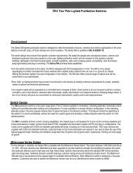
Typical<br />
3-Fastener<br />
Lockwire<br />
Installation<br />
1:42 *<br />
1 min. 42 sec.<br />
Typical<br />
3-Fastener<br />
<strong>Safe</strong>-T-<strong>Cable</strong> ®<br />
Installation<br />
<strong>Safe</strong>-T-<strong>Cable</strong> ® may be substituted, in many applications, for hand-twisted lockwire.<br />
<strong>Safe</strong>-T-<strong>Cable</strong> ® will improve the efficiency and quality of your assembly operations.<br />
© COPYRIGHT 2006 DANIELS MANUFACTURING CORP., ORLANDO, FL<br />
DANIELS ®<br />
MANUFACTURING<br />
CORPORATION<br />
an ISO9001 and AS9100 Registered Company<br />
0:36 *<br />
36 sec.<br />
*Assembly time comparison shown is for reference only.<br />
Actual time saved will be dependent upon the application.
• User Friendly Tooling<br />
• Lighter Weight Than Lockwire<br />
• Improved Security Of Fasteners<br />
• Considerable Reduction Of Rework<br />
• Minimal Operator Training Is Required<br />
• Simplified Installation Procedures<br />
• Reduces Installation And Inspection Time<br />
• <strong>Cable</strong> Tension Consistent On Each Application<br />
• Eliminates Injuries Due To Sharp Lockwire Ends<br />
• Reduces Risk Of Carpal Tunnel Injuries<br />
• Improved Access To Tight Areas<br />
DANIELS ®<br />
MANUFACTURING<br />
CORPORATION<br />
526 THORPE ROAD • ORLANDO, FL 32824-8133 USA<br />
(407) 855-6161 • FAX (407) 855-6884<br />
E-MAIL: DMC@DMCTOOLS.COM • WWW.DMCTOOLS.COM
Introducing <strong>Safe</strong>-T-<strong>Cable</strong> ® . . . . . . . . . . . . . 2<br />
About DMC . . . . . . . . . . . . . . . . . . . . . . . . . 3<br />
Approvals and Recognitions . . . . . . . . . . . 4<br />
DMC Statement on <strong>Safe</strong>-T-<strong>Cable</strong> ® . . . . . . . 5<br />
Users of <strong>Safe</strong>-T-<strong>Cable</strong> ® . . . . . . . . . . . . . . . 5<br />
<strong>Safe</strong>-T-<strong>Cable</strong> ® Part Numbering System. . . 6<br />
<strong>Safe</strong>-T-<strong>Cable</strong> ® Kits . . . . . . . . . . . . . . . . . . . 7<br />
<strong>Safe</strong>-T-<strong>Cable</strong> ® Assemblies and Ferrules . . 8<br />
© COPYRIGHT 2006 DANIELS MANUFACTURING CORP., ORLANDO, FL<br />
Table of Contents<br />
The Steps are Simple…<br />
THREAD<br />
A <strong>Cable</strong> assembly is threaded thru the fasteners<br />
in a direction which will exert a positive pull on<br />
the fastener when tension is applied.<br />
INSERT<br />
Elongated Ferrules . . . . . . . . . . . . . . . . . . . 9<br />
Fiberglass Sleeving . . . . . . . . . . . . . . . . . . 9<br />
Filler Washer. . . . . . . . . . . . . . . . . . . . . . . . 9<br />
Self-Looping <strong>Safe</strong>-T-<strong>Cable</strong> ® . . . . . . . . . . . 10<br />
Branded <strong>Safe</strong>-T-<strong>Cable</strong> ® . . . . . . . . . . . . . . 10<br />
Tool and Parts Kits . . . . . . . . . . . . . . . . . . 11<br />
Application Tools . . . . . . . . . . . . . . . . . . . 13<br />
Tool Accessories . . . . . . . . . . . . . . . . . . . 14<br />
Simply insert the cable through the ferrule<br />
cartridge and the tool nose.<br />
CRIMP & CUT<br />
Correct tension is applied, the ferrule is firmly<br />
crimped, and the cable is cut flush with the end<br />
of the ferrule.<br />
JOB IS FINISHED<br />
The job is complete. A secure installation in a<br />
fraction of the time it takes to install lockwire.<br />
Verification Equipment. . . . . . . . . . . . . . . 14<br />
.062 Diameter <strong>Safe</strong>-T-<strong>Cable</strong> ® . . . . . . . . . . 16<br />
Installation Practice Guide . . . . . . . . . . . 18<br />
FAA Classification Letter . . . . . . . . . . . . . 24<br />
F.A.R. Reference . . . . . . . . . . . . . . . . . . . . 25<br />
Limited Warranty . . . . . . . . . . . . . . . . . . . 25
Introducing<br />
Background<br />
There will always be a need to install<br />
constraining (safety) devices to threaded<br />
fasteners in applications where vibration,<br />
kinetic energy, or the need for high reliability<br />
is present. Their purpose is to<br />
restrict (to a minimum) the unintentional<br />
rotation of the fastener. The traditional<br />
method (devised in the early 1900’s)<br />
is through the use of Hand Twisted<br />
Lockwire (often called <strong>Safe</strong>ty wire).<br />
The only changes which have occurred<br />
since the early uses of Lockwire are the<br />
tremendous costs in the installation of<br />
this material, and the levels of sophistication<br />
in the systems on which Lockwire<br />
is being installed. It is used in Jet Engine<br />
PAGE 2<br />
Conventional Lockwire<br />
systems,<br />
Airframes,<br />
<strong>Electronic</strong>s,<br />
Space Vehicles,<br />
and Land/Sea based<br />
Systems.<br />
The process of installing lockwire<br />
remains awkward and costly, and the<br />
inspection process is demanding.<br />
The removal and rework of installed<br />
Lockwire is a common occurrence.<br />
<strong>Safe</strong>-T-<strong>Cable</strong> ®<br />
<strong>Safe</strong>-T-<strong>Cable</strong> ® was invented to address<br />
these problems in modern Airframe and<br />
Engine Systems. The <strong>Safe</strong>-T-<strong>Cable</strong> ®<br />
Kits are consistent in their construction/<br />
application, and the user-friendly tooling<br />
guarantees a secure and reliable installation<br />
each time it is used. Operator<br />
training is simple, Inspection is objective,<br />
and rework is virtually eliminated. This<br />
results in fewer demands on the Operators,<br />
Inspectors, and Maintenance personnel.<br />
Construction<br />
<strong>Safe</strong>-T-<strong>Cable</strong> ® is<br />
constructed of high<br />
tensile strength,<br />
stranded cable. It is<br />
more flexible than its<br />
Lockwire counterpart,<br />
although the working<br />
diameters are equivalent.<br />
This provides a<br />
stronger assembly<br />
which has greater<br />
strength and lighter<br />
weight. The cable<br />
ends are electrically<br />
fused to form an easy<br />
threading end.<br />
The cable is pre-cut to<br />
various lengths, and is supplied<br />
with a square-formed<br />
end cap attached to one end.<br />
<strong>Safe</strong>-T-<strong>Cable</strong> ® is available in<br />
three nominal diameters. The<br />
.040 inch diameter cable is constructed<br />
of 77 stranded ropelay<br />
material. Ropelay construction is also<br />
used for the 37, .032 diameter cable<br />
while the .022 diameter cable is made<br />
of 17 unilay material.<br />
Sectional View<br />
17 37<br />
77 719<br />
The ferrules are precisely manufactured<br />
to a size and hardness which<br />
assures their compatibility with the<br />
cable and application tooling. They are<br />
supplied (50 pieces each) in an easy<br />
loading disposable cartridge, which<br />
provides orderly containment of individual<br />
ferrules, and the easy release of<br />
individual ferrules as they are required.<br />
This feature minimizes the possibility<br />
of Foreign Object Damage (FOD).<br />
© COPYRIGHT 2006 DANIELS MANUFACTURING CORP., ORLANDO, FL • PHONE 407-855-6161 • FAX 407-855-6884 • E-MAIL: DMC@DMCTOOLS.COM • WWW.DMCTOOLS.COM
Testing<br />
The application of <strong>Safe</strong>-T-<strong>Cable</strong> ®<br />
is consistent from one installation to<br />
the next due to the repeatability and<br />
dependability of the application tooling<br />
and the quality of the materials used in<br />
the manufacture of <strong>Safe</strong>-T-<strong>Cable</strong> ® Kits.<br />
All that is required to assure overall<br />
reliability in manufacturing and maintenance<br />
use is a periodic test of a few<br />
crimped cable assemblies. DMC offers<br />
full instructions and the test equipment<br />
to perform these simple tests in either<br />
remote or test lab locations.<br />
Materials<br />
The same high performance alloys<br />
that are used in aerospace fasteners<br />
and other components are also used in<br />
the construction of <strong>Safe</strong>-T-<strong>Cable</strong> ® . The<br />
strength and corrosion resistance that<br />
is required for durability and long life. All<br />
components (End Fitting, <strong>Cable</strong>, and user<br />
applied Ferrule) are made of the same<br />
material. 321 Stainless Steel (AS3510)<br />
is the most common <strong>Safe</strong>-T-<strong>Cable</strong> ®<br />
material. It is used for most engine<br />
and airframe applications. Inconel 600<br />
(AS3509) is appropriate for high temperature<br />
and/or non-magnetic applications,<br />
and the new Inconel 625 (AS3655) has<br />
superior corrosion resistant properties.<br />
Consult DMC for further material<br />
selection information.<br />
About DMC…<br />
Daniels Manufacturing Corporation<br />
was selected to participate in the<br />
development of <strong>Safe</strong>-T-<strong>Cable</strong> ® early<br />
in the program based upon our expertise<br />
in the design and implementation<br />
of crimping, swaging, and fastening<br />
tools of many types.<br />
It was a reality to the inventor of<br />
<strong>Safe</strong>-T-<strong>Cable</strong> ® that the quality and<br />
repeatability of the application tool<br />
is the foundation to success in the<br />
development of <strong>Safe</strong>-T-<strong>Cable</strong> ® .<br />
DMC has been the leading manufacturer<br />
of crimping tools for the<br />
aircraft, aerospace, and high reliability<br />
<strong>Safe</strong>-T-<strong>Cable</strong> ®<br />
The pre-assembled cables have<br />
a square formed end cap securely<br />
attached to one end. This provides a<br />
positive stop when threaded through<br />
a fastener. The other end is electrically<br />
fused such that it will easily thread<br />
through the series of fasteners that are<br />
to be secured. The flexible cable material<br />
is lightweight and easy to handle. The<br />
stainless steel materials will not corrode<br />
or deteriorate while in use. (See chart<br />
on the following pages for material, size,<br />
and part number.) All <strong>Safe</strong>-T-<strong>Cable</strong> ® kits<br />
and assemblies are supplied 50 pieces<br />
per package.<br />
electronics industries for over 50 years.<br />
Our products are the standards of<br />
these industries, and DMC Products/<br />
Services are sold throughout the world.<br />
Other DMC Products include:<br />
Manual Crimping Tools, Pneumatic,<br />
Electric, and Hydraulic Crimping<br />
Tools, Backshell/Accessory Torque<br />
Tools, Contact Insertion/Removal<br />
Tools, EMI/RFI Shielding Band Tools,<br />
Alphatron Wire Crimp Pull Testers,<br />
Fiber Optic Cleave Tools, and Aircraft<br />
Maintenance Support Tool Kits.<br />
© COPYRIGHT 2006 DANIELS MANUFACTURING CORP., ORLANDO, FL • PHONE 407-855-6161 • FAX 407-855-6884 • E-MAIL: DMC@DMCTOOLS.COM • WWW.DMCTOOLS.COM<br />
Ferrules and<br />
Cartridge<br />
Loading System<br />
The individual crimp ferrules are<br />
preloaded into a disposable cartridge<br />
unit (50 pieces per cartridge) which allows<br />
convenient transportation, storage, and<br />
availability of these components. The<br />
ferrules are easily extracted individually<br />
by threading the cable end through the<br />
ferrule, and snapping the ferrule loose.<br />
This system, when properly used, eliminates<br />
the possibility of Foreign Object<br />
Damage (FOD).<br />
PAGE 3
U.S. Military<br />
NASM 33540<br />
(Formerly MIL-STD-33540)<br />
<strong>Safe</strong>ty Wiring, <strong>Safe</strong>ty Cabling,<br />
Cotter Pinning, General Practices<br />
This<br />
document<br />
is called<br />
out in many<br />
contracts,<br />
drawings,<br />
and process<br />
manuals.<br />
<strong>Safe</strong>-T-<br />
<strong>Cable</strong> ® was<br />
included<br />
in NASM<br />
33540 in<br />
revision 1,<br />
6 Jan, 2003.<br />
It is published<br />
and controlled by AIA<br />
(Aerospace Industries Association)<br />
http://www.aia-aerospace.org<br />
1250 Eye Street, Washington DC<br />
20005, and can be purchased<br />
on-line at the following web address:<br />
http://global.ihs.com/?RID=AIA<br />
Technical Manuals,<br />
Technical Orders,<br />
And MS Specs<br />
Many Tech Manuals and Tech Orders<br />
that are used by the U.S. Military and<br />
FMS Organizations to support Aircraft,<br />
Aerospace, and Defense Systems have<br />
been revised to include <strong>Safe</strong>-T-<strong>Cable</strong> ® .<br />
The technical information that is required<br />
to select, install, and maintain the <strong>Safe</strong>-<br />
T-<strong>Cable</strong> ® and Application/Verification<br />
Tooling is included. The General Tech<br />
Manuals/ Tech Orders are the following:<br />
PAGE 4<br />
Approvals And Recognitions<br />
TO-1-1A-8<br />
TO-1-1A-14<br />
TO-1-1A-15<br />
TM 1-1500-204-23-6<br />
TM 1-1500-323-24-1<br />
NAVAIR 01-1A-505<br />
NAVSEA MIL-STD-763<br />
ARMY MICOM, Drawing 13210868<br />
Several Platform Specific TOs and<br />
TMs feature instructions and guidelines<br />
for <strong>Safe</strong>-T-<strong>Cable</strong> ® . Consult the publications<br />
organization that supports your<br />
particular platform, or contact DMC<br />
for further information.<br />
National Stock<br />
Number Listing (NSN)<br />
The majority of <strong>Safe</strong>-T-<strong>Cable</strong> ® Tools<br />
and Components that are specified<br />
in Military Technical Manuals and<br />
Standards are covered by NSNs.<br />
Consult DMC for Details.<br />
SAE<br />
SAE International (Society of<br />
Automotive Engineers) maintains<br />
and distributes the procurement and<br />
detail specifications that control the<br />
design, packaging, and performance<br />
requirements of <strong>Safe</strong>-T-<strong>Cable</strong> ® . SAE<br />
Specifications are available on-line<br />
at www.sae.org, or at the following<br />
address:<br />
SAE INTERNATIONAL<br />
400 Commonwealth Drive<br />
Warrendale, OH 15044<br />
(724) 776-4841<br />
The List of <strong>Safe</strong>-T-<strong>Cable</strong> ® Specifications<br />
are the following:<br />
AS3509 <strong>Cable</strong>, <strong>Safe</strong>ty, Kit, Nickel Alloy,<br />
UNS N06600<br />
AS3510 <strong>Cable</strong>, <strong>Safe</strong>ty, Kit, Corrosion and<br />
Heat Resistant Steel, UNS S32100<br />
AS3511 <strong>Cable</strong>, <strong>Safe</strong>ty, Kit, Corrosion<br />
Resistant Steel, UNS S30400<br />
AS4536 <strong>Cable</strong>, <strong>Safe</strong>ty, Kit, Procurement<br />
Specification For Requirements<br />
and Use<br />
AS3618 <strong>Cable</strong>, <strong>Safe</strong>ty, Ferrule, Elongated,<br />
Corrosion and Heat Resistant<br />
Steel, UNS S32100<br />
AS3619 <strong>Cable</strong>, <strong>Safe</strong>ty, Ferrule, Elongated,<br />
Nickel Alloy, UNS N06600<br />
AS3620 <strong>Cable</strong>, <strong>Safe</strong>ty, Self Looping,<br />
Corrosion Resistant and Heat<br />
Resistant Steel, UNS S32100<br />
AS3621 <strong>Cable</strong>, <strong>Safe</strong>ty, Self-Looping,<br />
Nickel Alloy, UNS N06600<br />
AS3655 <strong>Cable</strong>, <strong>Safe</strong>ty, Kit, Corrosion<br />
Resistant Nickel Alloy, UNS N06625<br />
Please contact DMC for further<br />
information on SAE Specifications,<br />
Publication Status, or Application<br />
References.<br />
NASA<br />
The National Aeronautical and Space<br />
Administration, in cooperation with<br />
major contractors have developed<br />
several reports and standards involving<br />
the testing, selection, use, procurement,<br />
and application of <strong>Safe</strong>-T-<strong>Cable</strong> ® . Two<br />
significant NASA funded documents<br />
are CR4473 – CONTRACTOR REPORT<br />
(Intersel 1992), and JA83-032A<br />
Teledyne Brown.<br />
NASA Tech Briefs magazine has also<br />
recognized <strong>Safe</strong>-T-<strong>Cable</strong> ® as a modern<br />
Space Program Technology on one or<br />
more occasions. <strong>Safe</strong>-T-<strong>Cable</strong> ® is used<br />
on the Space Shuttle main orbiter engines,<br />
structure, and payload applications.<br />
© COPYRIGHT 2006 DANIELS MANUFACTURING CORP., ORLANDO, FL • PHONE 407-855-6161 • FAX 407-855-6884 • E-MAIL: DMC@DMCTOOLS.COM • WWW.DMCTOOLS.COM
FAA<br />
Many FAA Approved 70-XX-XX Standard Documents are published<br />
and maintained by major engine, airframe, and component/subsystem<br />
manufacturers.<br />
The FAA Approved Manual (supplied by the OEM) on the specific<br />
aircraft (or subsystem) will advise the operator/maintainer if <strong>Safe</strong>-T-<strong>Cable</strong> ®<br />
is approved by the OEM on that aircraft/application. If it can not be<br />
determined from this, or other documentation, the operator/maintainer<br />
should contact the OEM assigned representative, and request information<br />
concerning the use of <strong>Safe</strong>-T-<strong>Cable</strong> ® on that aircraft or subsystem.<br />
DMC Statement<br />
On <strong>Safe</strong>ty <strong>Cable</strong><br />
(<strong>Safe</strong>-T-<strong>Cable</strong> ® )<br />
Daniels Manufacturing Corporation, “DMC” manufactures and sells<br />
safety cable under license by General Electric Aircraft Engines in<br />
conformity with Society of Automotive Engineers Standard (SAE)<br />
Standard AS4536, AS3509, AS3510 and customer specifications.<br />
The Federal Aviation Administration (FAA) classified safety cable<br />
to be a standard part by issuance of a letter on November 23, 1993.<br />
This letter, in its entirety, along with the Federal Aviation Regulations<br />
(FAR) of that date referred to therein appears on the DMC Web Site,<br />
and on pages 24 and 25 of this catalog. The third paragraph of that<br />
letter states:<br />
Installation of AS3509, AS3510 and AS3511 safety cable on aircraft<br />
is governed by FAR § 43.13, Performance Rules (general). FAR § 43.13<br />
(a) states in part: “Each person performing maintenance, alteration, or<br />
preventative maintenance on an aircraft, engine, propeller, or appliance<br />
shall use the methods, techniques and practices prescribed in the<br />
current manufacturer’s maintenance manual or Instructions for Continued<br />
Airworthiness prepared by its manufacturer, or other methods, techniques,<br />
and practices acceptable to the Administrator…”<br />
It is the responsibility of the installer of safety cable to determine<br />
where safety cable can or cannot be installed in accordance with FAA<br />
regulations, OEM Practice Standards, or Department of Defense<br />
(DOD) directives. Where authorization is required, the installer should<br />
contact the Equipment OEM for the necessary authorization.<br />
DMC IS NOT LIABLE FOR CONSEQUENTIAL OR SPECIAL DAMAGES<br />
OF ANY NATURE OR KIND RESULTING FROM INSTALLATION<br />
OF SAFETY CABLE IN VIOLATION OF FAA, OEM, AND/OR DOD<br />
DIRECTIVES AND REGULATIONS.<br />
<strong>Safe</strong>ty <strong>Cable</strong> is a time saving technology. Please feel free to contact<br />
DMC for recommendations concerning the appropriate type of safety<br />
cable to be used for installation on authorized applications.<br />
The referenced FAA Letter, and copy of the referenced F.A.R. as of<br />
the date of the referenced letter, are shown on pages 24 and 25 of this<br />
catalog, and on the www.dmctools.com website.<br />
© COPYRIGHT 2006 DANIELS MANUFACTURING CORP., ORLANDO, FL<br />
Companies And<br />
Organizations Currently<br />
Using <strong>Safe</strong>-T-<strong>Cable</strong> ®<br />
(partial list)<br />
MANUFACTURERS<br />
AND GOVERNMENT<br />
ORGANIZATIONS<br />
Allison (Rolls Royce)<br />
American Eurocopter<br />
Argo Tech<br />
BAE Systems<br />
Bath Iron Works<br />
Bell Helicopter<br />
BF Goodrich Aerospace<br />
Boeing-Commercial<br />
Division<br />
Boeing-Military Division<br />
Boeing-Rocketdyne<br />
Boeing-Sea Launch<br />
Boeing-Space<br />
Bombardier Regionals<br />
Bombardier Shorts<br />
Bombardier Learjet<br />
Caterpillar<br />
Cessna Aircraft<br />
Dallas Airmotive<br />
Dassault Falcon<br />
Dyncorp<br />
Exelon<br />
Federal Aviation<br />
Administration (FAA)<br />
FPL Energy<br />
GE Aircraft Engines<br />
GE Transportation<br />
Systems<br />
GE Power Systems<br />
General Atomic<br />
General Dynamics<br />
Electric Boat<br />
General Dynamics<br />
Land Systems<br />
General Services<br />
Admin. (U.S. Gov.)<br />
Goodrich Aerospace<br />
Gulfstream Aerospace<br />
Hispano-Suiza<br />
Hamilton Sundstrand<br />
Harris (U.S. Army<br />
Missile Com.)<br />
Helicopter Support, Inc.<br />
Honeywell<br />
(Allied Signal)<br />
Honeywell (Garrett)<br />
Int'l Aero Engines (IAE)<br />
Kaman Aerospace<br />
Kelly Aerospace<br />
Kollsman<br />
L3 Aerospace Corp.<br />
L3 Vertex<br />
Learjet (Bombardier)<br />
Lockheed<br />
Aeronautical Co.<br />
Lockheed Missile<br />
& Space<br />
Lockheed Martin Corp.<br />
Lucas Aerospace<br />
Marine Mechanical<br />
Military<br />
(Air National Guard)<br />
Military (U.S. Army)<br />
Military (U.S. Air Force)<br />
Military (USMC)<br />
Military (NAVAIR)<br />
Military (NAVSEA)<br />
Mitsubishi<br />
Moog<br />
NASA<br />
Newport News<br />
Shipbuilding<br />
Northrop Grumman<br />
NOAA<br />
Pall Aeropower<br />
Parker Aerospace<br />
Petroleum Helicopters<br />
Pratt & Whitney (USA)<br />
Pratt & Whitney<br />
(Canada)<br />
Raytheon Aircraft<br />
Raytheon Systems<br />
Rohr Industries<br />
Rolls Royce<br />
SBAC (Scty British<br />
Aero Companies)<br />
Shorts Bros<br />
(Bombardier)<br />
Sikorsky Aircraft<br />
SNECMA<br />
Standard Aero<br />
Teledyne Brown<br />
Engineering<br />
Turbomeca<br />
U.S. Coast Guard<br />
Williams International<br />
Woodward Governor<br />
AIRLINES<br />
Air Canada<br />
Air China<br />
Air France<br />
Air New Zealand<br />
Alaska Airlines<br />
American Airlines<br />
ASA<br />
Atlantic Southeast<br />
Airlines<br />
Com Air<br />
Continental Airlines<br />
Delta Airlines<br />
FedEX<br />
Frontier Airlines<br />
Icelandair<br />
JetBlue<br />
Lufthansa<br />
Northwest Airlines<br />
Pinnacle Airlines<br />
Southwest Airlines<br />
UPS International<br />
US Airways
COMPONENTS<br />
C = Kit (<strong>Cable</strong> & Ferrule)<br />
A = Assemblies<br />
(<strong>Cable</strong> Only)<br />
F = Ferrules Only<br />
PAGE 6<br />
MATERIAL<br />
08 = INCONEL 625<br />
09 = INCONEL 600<br />
10 = 321 CRES<br />
Part Numbering System<br />
DMC Part No. System<br />
C10-218 XX<br />
AS3510-02 18K<br />
MATERIAL<br />
AS3509 = INCONEL 600<br />
AS3510 = 321 CRES<br />
AS3511 = 304 CRES (Consult DMC)<br />
AS3655 = INCONEL 625<br />
CABLE DIAMETER<br />
01 = .022 / .026<br />
02 = .032 / .038<br />
03 = .040 / .046<br />
04 = .062 / .072<br />
CONFIGURATION<br />
BLANK = Standard<br />
XX = Special* (Consult DMC)<br />
PKG. = One Part No. For Each<br />
50-Piece Package<br />
CABLE DIAMETER<br />
1 = .022 / .026<br />
2 = .032 / .038<br />
3 = .040 / .046<br />
4 = .062 / .072<br />
SAE Part No. System<br />
LENGTH<br />
9 = 9<br />
12 = 12<br />
15 = 15<br />
18 = 18<br />
21 = 21<br />
24 = 24<br />
LENGTH<br />
9 = 9<br />
12 = 12<br />
15 = 15<br />
18 = 18<br />
21 = 21<br />
24 = 24<br />
CONFIGURATION<br />
K = Kit (<strong>Cable</strong><br />
& Ferrule)<br />
C = <strong>Cable</strong><br />
Assembly<br />
(<strong>Cable</strong> Only)<br />
F = Ferrule<br />
(Ferrule Only)<br />
OTHER SAE PART NUMBERS – AS3618, AS3619 (Elongated Ferrules), AS3620, AS3621 (Self-Looping <strong>Cable</strong> Assemblies)<br />
*SPECIAL CONFIGURATION – Logo Stamp, Self-Looping <strong>Cable</strong>, etc. may require more than two characters. Consult DMC for details.<br />
COLOR CODE<br />
Standard packaging defines size by a standard DMC color code to avoid mixing ferrules and cable:<br />
.022 RED/PINK .032 BLUE .040 YELLOW .062 GREEN<br />
© COPYRIGHT 2006 DANIELS MANUFACTURING CORP., ORLANDO, FL • PHONE 407-855-6161 • FAX 407-855-6884 • E-MAIL: DMC@DMCTOOLS.COM • WWW.DMCTOOLS.COM
Time-Saving<br />
Elongated Ferrules<br />
For Low Profile Fastener Applications<br />
Most <strong>Safe</strong>-T-<strong>Cable</strong> ® installations can<br />
be made with standard components<br />
and application tools, however, there<br />
are conditions that require modification<br />
or alterations to the standard products.<br />
By addressing these exceptions, and<br />
extending the product lines to incorporate<br />
simple solutions to the difficult<br />
<strong>Safe</strong>-T-<strong>Cable</strong> ® applications, DMC has<br />
established itself as the industry leader.<br />
Fasteners that have limited clearance<br />
between the safety wire hole (less than<br />
.100 inch), and the surface of the component<br />
to which the fastener is attached,<br />
can present a challenge to the installation<br />
of <strong>Safe</strong>-T-<strong>Cable</strong> ® . This is due to the<br />
clearance required by the application<br />
tool nose, adjacent to the fastener.<br />
Fiberglass Sleeving<br />
Protective<br />
Jacketing<br />
Obstruction<br />
See previous page<br />
for elongated<br />
ferrule material,<br />
dimension and<br />
part number<br />
information.<br />
Protective<br />
Jacketing<br />
<strong>Safe</strong>-T-<strong>Cable</strong> ® Jacketing for Protection. It is<br />
recommended that a tubular jacket be placed<br />
over <strong>Safe</strong>-T-<strong>Cable</strong> ® when it is installed in an area<br />
where it will be in contact with obstructions or<br />
surfaces that may damage the <strong>Safe</strong>-T-<strong>Cable</strong> ® .<br />
The tubular jacket material shall be capable of<br />
meeting the temperature range of the application.<br />
It shall also be resistant to oil, and chemical<br />
environments.<br />
50-Foot Spool: Part No. SCTD010<br />
Square<br />
(both ends)<br />
Radius End*<br />
Square End<br />
A Special Elongated Ferrule<br />
is available for those installations. The<br />
longer reach of the ferrule provides a<br />
stand off to the tool nose. Combine<br />
that with the radius on the end next to<br />
the fastener (radius not required on the<br />
F10-08 .022 elongated ferrules due to<br />
the small outside diameter). The angle<br />
allows the ferrule to be installed at an<br />
angle without loss of tension on the<br />
cable when the ferrule returns to the<br />
straight position.<br />
*Radius featured on .032 and .040 ferrule<br />
diameters only.<br />
Standard<br />
Ferrule<br />
(short)<br />
Filler Washer<br />
Flat Washer<br />
© COPYRIGHT 2006 DANIELS MANUFACTURING CORP., ORLANDO, FL • PHONE 407-855-6161 • FAX 407-855-6884 • E-MAIL: DMC@DMCTOOLS.COM • WWW.DMCTOOLS.COM PAGE 9<br />
Tool<br />
Nose<br />
Options<br />
Dia.<br />
Length<br />
Incorrect Correct<br />
Elongated Ferrule<br />
(Radius<br />
End<br />
Toward<br />
Fastener)<br />
Tool Nose<br />
Elongated<br />
Ferrule<br />
Figure 1: Flat Washer <strong>Safe</strong>-T-<strong>Cable</strong> ® Installation<br />
Applications where <strong>Safe</strong>-T-<strong>Cable</strong> ® is to be installed<br />
through a hole having a diameter greater than<br />
.095 inch, (2.4mm), but less than .200 inch (5.08mm)<br />
can be accommodated by a filler washer.<br />
NOTE: Compatible materials are required, and<br />
care must be taken to restrain the washer during<br />
removal/service operations.<br />
Filler Washer • Material 321 CRES • Part No. FW10-1
DMC1000-4R<br />
Tool And Parts Kits<br />
DMC Offers Complete<br />
Tool And Parts Kits<br />
To Support Your<br />
DMC is well known throughout the aerospace industry for the<br />
quality and capability of the Tool Kits that we manufacture.<br />
The packaging materials (case, inserts, and instructions)<br />
are manufactured to specifically meet the most<br />
demanding handling conditions.<br />
FOD (Foreign Object Damage) is always a<br />
concern when workers are required to use<br />
tools and small components in or around<br />
an aircraft. The DMC <strong>Safe</strong>-T-<strong>Cable</strong> ® kits<br />
are designed to minimize that concern.<br />
The “shadowing” principal is a proven<br />
concept for Tool/parts control.<br />
<strong>Safe</strong>-T-<strong>Cable</strong> ® Tool and Parts Kits are<br />
available in a variety of configurations to<br />
support your specific requirements. Our most<br />
requested Tool & Parts Kit is the DMC1000-4R due to the<br />
popularity of .032 diameter <strong>Safe</strong>-T-<strong>Cable</strong> ® , and the demand for a<br />
travel-ready system whereby the user has Tools, Verification Equipment,<br />
Accessories, a supply of <strong>Cable</strong>/Ferrules, and the Instructions all in one package.<br />
Other Kits are available to support your particular needs. The most popular<br />
selections are listed on the following page.<br />
If you have specific needs that cannot be covered by the Tool Kits that are<br />
described here, please call a DMC customer service representative for<br />
information on a Kit that will more appropriately meet your requirements.<br />
DMC1000-4R .032 <strong>Safe</strong>-T-<strong>Cable</strong> ® Tool and Parts Kit<br />
PART NUMBER QUANTITY DESCRIPTION<br />
SCTR323 1 <strong>Safe</strong>-T-<strong>Cable</strong> ® Tool with 3 Nose Attached (.032)<br />
SCTN32-7 1 7 Nose Assembly (.032)<br />
C10-218 100 <strong>Safe</strong>-T-<strong>Cable</strong> ® (.032 x 18)<br />
SCT-TB1 1 <strong>Safe</strong>-T-<strong>Cable</strong> ® Torque Verification Block<br />
4-1501 1 9/64 Hex Wrench<br />
SDD440 1 Screwdriver<br />
45-6N 1 Diagonal Cutter/Gripper<br />
SCT32084 1 Spanner Tool<br />
Applications.<br />
© COPYRIGHT 2006 DANIELS MANUFACTURING CORP., ORLANDO, FL • PHONE 407-855-6161 • FAX 407-855-6884 • E-MAIL: DMC@DMCTOOLS.COM • WWW.DMCTOOLS.COM PAGE 11
PAGE 12<br />
Tool And Parts Kits<br />
DMC1001-7R .022 <strong>Safe</strong>-T-<strong>Cable</strong> ® Tool and Parts Kit<br />
PART NUMBER QUANTITY DESCRIPTION<br />
SCTR203 1 <strong>Safe</strong>-T-<strong>Cable</strong> ® Tool with 3 Nose Attached (.022)<br />
SCTN20-7 1 7 Nose Assembly (.022)<br />
C10-118 100 <strong>Safe</strong>-T-<strong>Cable</strong> ® (.022 x 18)<br />
SCT-TB1 1 <strong>Safe</strong>-T-<strong>Cable</strong> ® Torque Verification Block<br />
4-1501 1 9/64 Hex Wrench<br />
SDD440 1 Screwdriver<br />
45-6N 1 Diagonal Cutter/Gripper<br />
SCT32084 1 Spanner Tool<br />
DMC1000-20R .022 & .032 <strong>Safe</strong>-T-<strong>Cable</strong> ® Tool and Parts Kit<br />
PART NUMBER QUANTITY DESCRIPTION<br />
SCTR323 1 <strong>Safe</strong>-T-<strong>Cable</strong> ® Tool with 3 Nose Attached (.032)<br />
SCTR203 1 <strong>Safe</strong>-T-<strong>Cable</strong> ® Tool with 3 Nose Attached (.022)<br />
SCTN32-7 1 7 Nose Assembly (.032)<br />
SCTN20-7 1 7 Nose Assembly (.022)<br />
C10-218 100 <strong>Safe</strong>-T-<strong>Cable</strong> ® (.032 x 18)<br />
C10-118 100 <strong>Safe</strong>-T-<strong>Cable</strong> ® (.022 x 18)<br />
C10-218JA 50 Self-Looping <strong>Safe</strong>-T-<strong>Cable</strong> ® (.032 x 18)<br />
SCT-TB1 1 <strong>Safe</strong>-T-<strong>Cable</strong> ® Torque Verification Block<br />
4-1501 1 9/64 Hex Wrench<br />
F10-04 50 Elongated Ferrules (.032)<br />
SCT32084 1 Spanner Tool<br />
SDD440 1 Screwdriver<br />
45-6N 1 Diagonal Cutter Gripper<br />
PART NUMBER QUANTITY DESCRIPTION<br />
SCTR407 1 <strong>Safe</strong>-T-<strong>Cable</strong> ® Tool with 7 Nose Attached (.040)<br />
C10-318 100 <strong>Safe</strong>-T-<strong>Cable</strong> ® (.040 x 18)<br />
SCT-TB1 1 <strong>Safe</strong>-T-<strong>Cable</strong> ® DMC1000-11R .040 <strong>Safe</strong>-T-<strong>Cable</strong><br />
Torque Verification Block<br />
4-1501 1 9/64 Hex Wrench<br />
SDD440 1 Screwdriver<br />
45-6N 1 Diagonal Cutter/Gripper<br />
SCT32084 1 Spanner Tool<br />
® Tool and Parts Kit<br />
DMC1007-28R Master Kit (.022, .032, and .040 <strong>Safe</strong>-T-<strong>Cable</strong> ® )<br />
PART NUMBER QUANTITY DESCRIPTION<br />
SCTR203 1 <strong>Safe</strong>-T-<strong>Cable</strong> ® Tool with 3 Nose Attached (.022)<br />
SCTR323 1 <strong>Safe</strong>-T-<strong>Cable</strong> ® Tool with 3 Nose Attached (.032)<br />
SCTR403 1 <strong>Safe</strong>-T-<strong>Cable</strong> ® Tool with 3 Nose Attached (.040)<br />
SCTN20-7 1 7 Nose Assembly (.022)<br />
SCTN32-7 1 7 Nose Assembly (.032)<br />
SCTN32-7 1 7 Nose Assembly (.040)<br />
SCT-TB1 1 Torque Verification Block<br />
SCT32084 1 Spanner Tool<br />
SDD440 1 Screwdriver<br />
4-1501 1 9/64 Hex Wrench<br />
45-6N 1 Diagonal Cutter/Gripper<br />
C10-118 100 <strong>Safe</strong>-T-<strong>Cable</strong> ® (.022 x 18)<br />
C10-118JA 50 Self-Looping <strong>Safe</strong>-T-<strong>Cable</strong> ® (.022)<br />
C10-218 100 <strong>Safe</strong>-T-<strong>Cable</strong> ® (.032)<br />
C10-218JA 50 Self-Looping <strong>Safe</strong>-T-<strong>Cable</strong> ® (.032)<br />
C10-318 100 <strong>Safe</strong>-T-<strong>Cable</strong> ® (.040)<br />
C10-318JA 50 Self-Looping <strong>Safe</strong>-T-<strong>Cable</strong> ® (.040)<br />
F10-04 50 Elongated Ferrules (.022)<br />
F10-07 50 Elongated Ferrules (.032)<br />
F10-08 50 Elongated Ferrules (.040)<br />
© COPYRIGHT 2006 DANIELS MANUFACTURING CORP., ORLANDO, FL • PHONE 407-855-6161 • FAX 407-855-6884 • E-MAIL: DMC@DMCTOOLS.COM • WWW.DMCTOOLS.COM
It’s a Matter of Choice…<br />
Over 50 years of success in the design, production, and support of tooling for high-reliability applications in the aircraft and<br />
aerospace industry is the reason DMC was included in the development team for <strong>Safe</strong>-T-<strong>Cable</strong> ® . The Tooling, which was initially<br />
designed to meet the challenges of <strong>Safe</strong>-T-<strong>Cable</strong> ® installation, has evolved into a product line that is flexible enough to meet<br />
the users’ exact needs. It’s your choice as to which model and accessories to specify, but always with the understanding that<br />
interchangeability, adjustability, and overall reliability was the basis of each application tool series.<br />
Adjustable Tension<br />
Hand Tool Series<br />
The most popular hand operated application tool for<br />
<strong>Safe</strong>-T-<strong>Cable</strong> ® is the SCTR Series Adjustable Tension<br />
Tool. The tool features replaceable noses of various<br />
lengths (see chart on page 14), and a rotary tension<br />
mechanism which can be adjusted to precise cable<br />
tension requirements. The tension will repeat at<br />
the setting which has been selected for reliable<br />
<strong>Safe</strong>-T-<strong>Cable</strong> ® installations.<br />
Pre-Set Tension<br />
Hand Tool Series<br />
In some factories where control of tool adjustments<br />
are not possible, where the skill level is minimal, or applications<br />
where a single-handed operation of the tool<br />
is desirable, the SCT Series Application Tool may be<br />
the best choice. All tools in this series feature a patented<br />
tension mechanism, which allows single-handed use of<br />
the tool (after the cable is threaded through and into the<br />
tool). Multiple actuations of the tool handle will draw the<br />
cable into the tool until all slack is removed from the cable.<br />
When the tool senses the correct tension (pre-set at<br />
the factory), it will shift into the crimp-cut mode, and<br />
complete the installation of the <strong>Safe</strong>-T-<strong>Cable</strong> ® on the<br />
next closure of the handle. It’s as simple as that.<br />
Pneumatic Application<br />
Tool Series<br />
When ergonomics and production demands are critical<br />
issues, the DMC SCTPR (No. 3) and SCTP (No. 4) Series<br />
Pneumatic Application Tool are a must. <strong>Safe</strong>-T-<strong>Cable</strong> ® is<br />
threaded through the fasteners, into the ferrule, and into<br />
the tool in the same fashion as the manual tools, but<br />
the push of a button is all that is necessary to complete<br />
the termination. The tool automatically applies tension<br />
(adjustable), crimps and cuts flush in one actuation of<br />
the trigger. These tools operate on standard shop air<br />
pressure, and may be suspended from a load balancer<br />
for an even greater improvement in ergonomics.<br />
Application Tools<br />
Battery Powered<br />
Tool Series<br />
The DMC SCTE Series Battery Powered<br />
<strong>Safe</strong>-T-<strong>Cable</strong> ® tool is an ergonomic alternative to<br />
the other <strong>Safe</strong>-T-<strong>Cable</strong> ® Application Tools where<br />
a portable tool, without a hose or cord is required.<br />
The self contained hydraulic crimp system is reliable<br />
and the tool accommodates the same changeable<br />
noses and other accessories that are interchangeable<br />
with other DMC <strong>Safe</strong>-T-<strong>Cable</strong> ® Application Tools.<br />
© COPYRIGHT 2006 DANIELS MANUFACTURING CORP., ORLANDO, FL • PHONE 407-855-6161 • FAX 407-855-6884 • E-MAIL: DMC@DMCTOOLS.COM • WWW.DMCTOOLS.COM PAGE 13
Adjustable<br />
Tension<br />
Hand Tool<br />
Series<br />
Pre-Set<br />
Tension<br />
Hand Tool<br />
Series<br />
Pneumatic<br />
Application<br />
Tool Series<br />
Battery<br />
Powered<br />
Application<br />
Tool Series<br />
Replacement<br />
Noses<br />
MPT-250B-SC<br />
Motorized pull<br />
tester for testing<br />
.022, 032 and .040<br />
<strong>Safe</strong>-T-<strong>Cable</strong> ® .<br />
PAGE 14<br />
DMC<br />
PART NUMBER<br />
CABLE<br />
DIAMETER<br />
(INCHES)<br />
Tools, Accessories And<br />
Verification Equipment<br />
NOSE<br />
LENGTH<br />
(INCHES)<br />
SCTR203 .022 3<br />
SCTR207 .022 7<br />
SCTR323 .032 3<br />
SCTR327 .032 7<br />
SCTR403 .040 3<br />
SCTR407 .040 7<br />
SCT203 .022 3<br />
SCT207 .022 7<br />
SCT323 .032 3<br />
SCT327 .032 7<br />
SCT403 .040 3<br />
SCT407 .040 7<br />
ADJUSTABLE PRE-SET<br />
SCTPR203 SCTP203 .022 3<br />
SCTPR207 SCTP207 .022 7<br />
SCTPR323 SCTP323 .032 3<br />
SCTPR327 SCTP327 .032 7<br />
SCTPR403 SCTP403 .040 3<br />
SCTPR407 SCTP407 .040 7<br />
Note: SCTPR Series Tools are preferred where precise tension adjustments are needed.<br />
SCTE203 .022 3<br />
SCTE207 .022 7<br />
SCTE323 .032 3<br />
SCTE327 .032 7<br />
SCTE403 .040 3<br />
SCTE407 .040 7<br />
SCTN20-3 .022 3<br />
SCTN20-5 .022 5<br />
SCTN20-7 .022 7<br />
SCTN32-3 .032 3<br />
SCTN32-5 .032 5<br />
SCTN32-7 .032 7<br />
SCTN40-3 .040 3<br />
SCTN40-5 .040 5<br />
SCTN40-7 .040 7<br />
Tool Performance<br />
Verification<br />
Equipment<br />
Repeatability and traceability in the<br />
management of <strong>Safe</strong>-T-<strong>Cable</strong> ® tools<br />
at all stages of their life cycle requires<br />
periodic testing and verification. DMC<br />
supplies all the equipment necessary<br />
to perform a quick reliable verification<br />
of the application tools either on-sight,<br />
or in the metrology lab. Our objective<br />
has always been to provide a selfsupporting<br />
system that does not require<br />
that tools be returned to the factory for<br />
simple testing and verification.<br />
SCT-TB1<br />
Torque verification block for .022,<br />
.032, and .040 <strong>Safe</strong>-T-<strong>Cable</strong> ® .<br />
SCT-TB1R<br />
Torque verification block configured for<br />
right-hand reading torque wrenches.<br />
SCTD0001<br />
Torque wrench for .022, .032,<br />
and .040 <strong>Safe</strong>-T-<strong>Cable</strong> ® .<br />
SCTD013<br />
2 lb. push force tester for use with<br />
<strong>Safe</strong>-T-<strong>Cable</strong> ® torque verification block.<br />
Refer to <strong>Safe</strong>-T-<strong>Cable</strong> ®<br />
application tool instructions<br />
for information on<br />
Tool Performance Verification.<br />
© COPYRIGHT 2006 DANIELS MANUFACTURING CORP., ORLANDO, FL • PHONE 407-855-6161 • FAX 407-855-6884 • E-MAIL: DMC@DMCTOOLS.COM • WWW.DMCTOOLS.COM
SCT-TB4 Portable<br />
Verification Tester<br />
Advanced Technology for<br />
<strong>Safe</strong>-T-<strong>Cable</strong> ® Application Tool Testing<br />
The SCT-TB4 <strong>Safe</strong>-T-<strong>Cable</strong> ® <strong>Electronic</strong> Verification Tester is a complete diagnostic<br />
center for <strong>Safe</strong>-T-<strong>Cable</strong> ® application tools. The SCT-TB4 is the first system approach<br />
tester for optimum <strong>Safe</strong>-T-<strong>Cable</strong> ® installation performance. It combines the simple<br />
principals of the DMC <strong>Safe</strong>-T-<strong>Cable</strong> ®<br />
Torque Verification Block (SCT-TB1)<br />
and the reliable circuitry of the<br />
Alphatron “HPT” series digital<br />
electronic pull tester.<br />
This one tester will provide<br />
all the information that<br />
previously required two<br />
separate testers, and<br />
increased consumption<br />
of <strong>Safe</strong>-T-<strong>Cable</strong> ® for<br />
verification of application<br />
tools. A single installed<br />
cable assembly can first<br />
be tested for minimum<br />
load – hold (flex limit<br />
test), and then be tested<br />
to destruct load (optimum tool<br />
performance). The SCT-TB4 Tester<br />
will also provide applied tension and<br />
residual tension data for engineering<br />
study and employee training purposes.<br />
The SCT-TB4 tester is designed and packaged to survive in a shop environment,<br />
and the self contained, battery powered, design allows the user to perform tests<br />
in all areas of the shop and field support activities.<br />
The SCT-TB4 Tester is a cost-effective quality assurance tool in most factory and<br />
maintenance applications where <strong>Safe</strong>-T-<strong>Cable</strong> ® is used.<br />
Special Tools and Accessories<br />
DMC extends the capabilities of the <strong>Safe</strong>-T-<strong>Cable</strong> ® Product Line by making available the following accessories and tools:<br />
SCT32084<br />
Spanner Tool is for<br />
adjusting all <strong>Safe</strong>-T-<strong>Cable</strong> ®<br />
Application Tools<br />
(one spanner is supplied<br />
with each new tool).<br />
SCT32059SA<br />
Nose Extender<br />
adds two inches in<br />
length. Can be used<br />
with any tool/nose<br />
combination.<br />
Tension Assembly<br />
Required for conversion of any SCTR<br />
Tool from one cable size to another.<br />
SCTR20TW-SA .022 Dia.<br />
SCTR32TW-SA .032 Dia.<br />
SCTR40TW-SA .040 Dia.<br />
• All DMC testers have<br />
a built-in calibration<br />
test<br />
• SPC compatible<br />
• Traceable to NIST<br />
• Factory calibration<br />
and support<br />
• Rugged design, and<br />
custom carry case<br />
included<br />
• One sample testing<br />
to the requirements<br />
of AS4536 and other<br />
standards<br />
• Improves tool control<br />
and calibration<br />
operations<br />
45-6N<br />
Cutter/Gripper for<br />
.022, .032 and .040<br />
<strong>Safe</strong>-T-<strong>Cable</strong> ®<br />
and Lockwire<br />
© COPYRIGHT 2006 DANIELS MANUFACTURING CORP., ORLANDO, FL • PHONE 407-855-6161 • FAX 407-855-6884 • E-MAIL: DMC@DMCTOOLS.COM • WWW.DMCTOOLS.COM PAGE 15
.062 (Locking <strong>Cable</strong>)<br />
PAGE 16<br />
Conventional Lockwire<br />
<strong>Safe</strong>-T-<strong>Cable</strong> ®<br />
An urgent need for a fast reliable<br />
fastener security system for the Nuclear<br />
Power Industry resulted in the further<br />
expansion of <strong>Safe</strong>-T-<strong>Cable</strong> ® (Locking<br />
<strong>Cable</strong>) by DMC. Working with a major<br />
contractor to NAVSEA and commercial<br />
power organizations, DMC developed<br />
and certified a .062 diameter <strong>Safe</strong>-T-<strong>Cable</strong> ®<br />
for use onboard nuclear submarines, and<br />
carriers. The .062 diameter <strong>Safe</strong>-T-<strong>Cable</strong> ®<br />
(Locking <strong>Cable</strong>) was later tested and<br />
certified for use by the commercial<br />
power industry, aircraft applications,<br />
and industrial use. The practice of twisting<br />
lockwire onto fasteners and threaded<br />
assemblies is a tedious task, which<br />
requires skill and time. Lockwire measuring<br />
.062 diameter is anything but “user<br />
friendly”. <strong>Safe</strong>-T-<strong>Cable</strong> ® (Locking <strong>Cable</strong>)<br />
allows maintenance and other operations<br />
to be performed in the minimum time, in<br />
tight access areas, with limited inspection,<br />
and with no rework due to faulty<br />
lockwiring. Also, handling the tool and<br />
materials for <strong>Safe</strong>-T-<strong>Cable</strong> ® (Locking<br />
<strong>Cable</strong>) will not damage special gloves<br />
or protective clothing.<br />
.032 and .062 diameter <strong>Safe</strong>-T-<strong>Cable</strong> ®<br />
(Locking <strong>Cable</strong>) is recognized and<br />
defined in MIL-STD-763 (G Revision).<br />
Construction: The standard .062<br />
diameter <strong>Safe</strong>-T-<strong>Cable</strong> ® (Locking <strong>Cable</strong>)<br />
is 24 inches in length, and measures<br />
.062 min./.072 inch max. diameter. The<br />
cable is comprised of 7 strands of 19<br />
wires each for maximum strength and<br />
flexibility. The factory-applied end fitting<br />
(square) measures approximately .155<br />
inch across the flats, and the outside<br />
Other Nose<br />
Length Tools<br />
Are Available<br />
(See Chart<br />
Next Page)<br />
diameter of the user applied ferrule<br />
measures .150 inch. The minimum<br />
pull-off load of the ferrule after crimping<br />
is 280 pounds (per Mil-Std 763). Product<br />
samples, application information, and<br />
technical data may be obtained by<br />
contacting DMC.<br />
Two application tools are available<br />
from DMC, and two installation kits<br />
are also available.<br />
The Hydraulic Application Tool<br />
(part number SCTH625) utilizes a<br />
lightweight hand actuated hydraulic<br />
pump to develop the force required<br />
to crimp and cut the .062 diameter<br />
<strong>Safe</strong>-T-<strong>Cable</strong> ® (Locking <strong>Cable</strong>).<br />
The tool crimps and cuts the<br />
assembly flush to the ferrule by<br />
multiple actuation of a single handle.<br />
The Battery Powered Hydraulic<br />
Application Tool (part number<br />
SCTE625) provides the same reliable<br />
<strong>Safe</strong>-T-<strong>Cable</strong> ® termination by pressing<br />
a trigger. This tool is lightweight and<br />
self-contained. The Nicad battery<br />
is rechargeable (charger supplied).<br />
SCTH 625<br />
SCTE 625<br />
SCT-TB2<br />
SCT-D011<br />
© COPYRIGHT 2006 DANIELS MANUFACTURING CORP., ORLANDO, FL • PHONE 407-855-6161 • FAX 407-855-6884 • E-MAIL: DMC@DMCTOOLS.COM • WWW.DMCTOOLS.COM
.062 (Locking <strong>Cable</strong>)<br />
DMC1000-62 NAV Soft Canvas Case<br />
OPTIONAL CONFIGURATION FLANGE<br />
FITTINGS FOR FASTENERS WITH<br />
HOLES UP TO 8 MM DIAMETER<br />
Crimp Ferrule <strong>Cable</strong> End Fitting<br />
Consult DMC for Part Numbers<br />
and Availability<br />
.062 Tool & Parts Kits<br />
DMC1000-62NAV<br />
Soft Case Support Kit<br />
PARTS LIST<br />
PART NUMBER QUANTITY DESCRIPTION<br />
SCTH625 1 .062 <strong>Safe</strong>-T-<strong>Cable</strong> ® Hydraulic Tool with 5 Nose<br />
SCTHN62-9 1 .062 Nose Assembly 9 Long<br />
A10-924 250 <strong>Safe</strong>-T-<strong>Cable</strong> ® .062 x 24<br />
F10-9 250 <strong>Safe</strong>-T-<strong>Cable</strong> ® Ferrule, .062<br />
SCTD015 1 .062 Diagonal Cutter<br />
4-1136 1 3/32 Hex Wrench<br />
SCTD012 1 Retaining Ring Pliers<br />
565B 1 Drive Punch<br />
SCTD011 1 Torque Wrench 100–750 Pounds<br />
SCT-TB2 1 Torque Verification Block<br />
1 Handbook (Instructions)<br />
.062 CABLE KITS* (ONE CABLE AND ONE FERRULE)<br />
LENGTH 321 CRES INCONEL 625 INCONEL 600<br />
18 C10-918 Consult DMC C09-918<br />
24 C10-924 Consult DMC C09-924<br />
30 C10-930 Consult DMC C09-930<br />
.062 CABLE ASSEMBLY* (CABLE ONLY – NO FERRULE)<br />
18 A10-918 Consult DMC A09-918<br />
24 A10-924 Consult DMC A09-924<br />
30 A10-930 Consult DMC A09-930<br />
.062 FERRULES* (STANDARD AND ELONGATED)<br />
Standard F10-9 Consult DMC F09-9<br />
Elongated F10-10 Consult DMC Consult DMC<br />
.062 TOOLS AND ACCESSORIES<br />
SCTH 625 Manual Hydraulic Application Tool with 5 Nose<br />
SCTH 629 Manual Hydraulic Application Tool with 9 Nose<br />
SCTE 625 Battery Powered Application Tool with 5 Nose<br />
SCTE 629 Battery Powered Application Tool with 9 Nose<br />
SCTN 62-5 Replacement Nose – 5 Length<br />
SCTN 62-9 Replacement Nose – 9 Length<br />
SCT-TB2 Torque Verification Block for .062 <strong>Safe</strong>-T-<strong>Cable</strong> ®<br />
SCTD011 Torque Wrench – 100 to 750 Pound Range<br />
SCTD015 <strong>Cable</strong> Cutter/Gripper<br />
SCTD012 Retaining Ring Plier<br />
*Supplied in packages of 50 pieces.<br />
**Add “PKG” to part number when ordering a 50 piece bag of cable and/or ferrules.<br />
DMC1000-625<br />
Hard Case Support Kit<br />
PARTS LIST<br />
PART NUMBER QUANTITY DESCRIPTION<br />
SCTH625 1 .062 <strong>Safe</strong>-T-<strong>Cable</strong> ® Hydraulic Tool with 5 Nose<br />
C10-924 100 <strong>Safe</strong>-T-<strong>Cable</strong> ® 321 CRES .062 24<br />
SCT-TB2 1 <strong>Safe</strong>-T-<strong>Cable</strong> ® Torque Verification Block<br />
SCTD015 1 Diagonal Cutter<br />
SCT32084 1 Spanner Tool<br />
SCTD011 1 Torque Wrench 100–750 Inch Pound<br />
SCTD012 1 Retaining Ring Pliers<br />
4-1501 1 9/64 Hex Wrench<br />
565B 1 Drive Punch<br />
© COPYRIGHT 2006 DANIELS MANUFACTURING CORP., ORLANDO, FL • PHONE 407-855-6161 • FAX 407-855-6884 • E-MAIL: DMC@DMCTOOLS.COM • WWW.DMCTOOLS.COM PAGE 17
Installation<br />
Practice Guide<br />
1. <strong>Safe</strong>-T-<strong>Cable</strong> ®<br />
1.1. General Instructions for the selection of<br />
<strong>Safe</strong>-T-<strong>Cable</strong> ® . The selection of materials shall be in<br />
accordance with AS4536 (SAE), available from SAE<br />
International, 400 Commonwealth Avenue, Warrendale,<br />
PA 15096-0001, and shall be in accordance with the<br />
service limitations outlined herein.<br />
NOTE<br />
Minimize mixing of safety wire and <strong>Safe</strong>-T-<strong>Cable</strong> ® .<br />
1.1.1. AS3510 series (UNS S32100 CRES) <strong>Safe</strong>-T-<strong>Cable</strong> ®<br />
shall be selected for general purpose use on all applications<br />
up to 800° F.<br />
1.1.2. AS3509 series (UNS N6600 Nickel Alloy)<br />
<strong>Safe</strong>-T-<strong>Cable</strong> ® shall be selected for applications where<br />
temperature range is between 800° F and 1500° F.<br />
1.1.3. Only <strong>Safe</strong>-T-<strong>Cable</strong> ® and ferrules supplied by a<br />
manufacturer that meets all the requirements of AS4536<br />
shall be allowed.<br />
1.1.4. <strong>Safe</strong>-T-<strong>Cable</strong> ® shall not be used for any shear,<br />
or break away applications.<br />
1.1.5. <strong>Safe</strong>-T-<strong>Cable</strong> ® shall be installed with a calibrated<br />
tool which is supplied by the <strong>Safe</strong>-T-<strong>Cable</strong> ® manufacturer<br />
for the purpose of applying a predetermined cable tension,<br />
crimping the ferrule, and cutting the excess cable without<br />
allowing tension to be lost.<br />
1.2 The size of <strong>Safe</strong>-T-<strong>Cable</strong> ® shall be in accordance<br />
with the following requirements:<br />
1.2.1. 0.022 inch diameter <strong>Safe</strong>-T-<strong>Cable</strong> ® is intended<br />
for use on parts having a nominal hole diameter of 0.045<br />
inch (1.14 mm) or smaller.<br />
1.2.2 0.032 inch diameter <strong>Safe</strong>-T-<strong>Cable</strong> ® is intended<br />
for use on parts having a nominal hole diameter of 0.075<br />
inch (1.91 mm) or smaller.<br />
1.2.3. 0.040 inch diameter <strong>Safe</strong>-T-<strong>Cable</strong> ® is intended<br />
for use on parts having a nominal hole diameter of 0.095<br />
inch (2.41 mm) or smaller.<br />
1.2.4. The specified length of the cable shall be selected<br />
to accommodate the span between fasteners added<br />
to the length of cable required to correctly engage the<br />
application tool.<br />
PAGE 18<br />
<strong>Safe</strong>-T-<strong>Cable</strong> ® Application/Installation information which appears<br />
on these pages was adapted from a U.S. Military Handbook.<br />
It is intended for reference only. It is the responsibility<br />
of the user to verify and confirm that the installation of<br />
<strong>Safe</strong>-T-<strong>Cable</strong> ® is safe and appropriate for the application.<br />
FIGURE 1: Flat Washer <strong>Safe</strong>-T-<strong>Cable</strong> ® Installation<br />
1.2.5. Applications where <strong>Safe</strong>-T-<strong>Cable</strong> ® is to be<br />
installed through a hole having a nominal diameter of<br />
greater than .095 inch (2.41 mm), but less than .200<br />
inch (5.08 mm) shall require a flat washer (same material<br />
composition as the <strong>Safe</strong>-T-<strong>Cable</strong> ® ) which is supplied by<br />
the <strong>Safe</strong>-T-<strong>Cable</strong> ® manufacturer for this purpose, and<br />
shall be used as shown in Figure 1.<br />
1.2.6. <strong>Safe</strong>-T-<strong>Cable</strong> ® shall be installed with an application<br />
tool which has been calibrated to meet the performance<br />
requirements of AS4536 (SAE) and this manual.<br />
1.3. <strong>Safe</strong>-T-<strong>Cable</strong> ® Installation. <strong>Safe</strong>-T-<strong>Cable</strong> ® may be<br />
used as a substitute for lockwire to prevent loosening<br />
during service. Threaded parts, such as drilled-head<br />
bolts, fillister head screws, turnbuckles, thumbscrews,<br />
hose fittings and electrical connectors, plugs, caps, and<br />
similar items are within the scope of the <strong>Safe</strong>-T-<strong>Cable</strong> ®<br />
application. The following rules shall apply when using<br />
<strong>Safe</strong>-T-<strong>Cable</strong> ® .<br />
NOTE<br />
Routing of <strong>Safe</strong>-T-<strong>Cable</strong> ® may vary from that of lockwire<br />
in order to achieve a proper installation.<br />
1.3.1. When <strong>Safe</strong>-T-<strong>Cable</strong> ® is being substituted for<br />
lockwire in an existing installation (maintenance, rework,<br />
etc.), equivalent diameter <strong>Safe</strong>-T-<strong>Cable</strong> ® to that of the<br />
lockwire shall be selected for use, providing that selection<br />
criteria for <strong>Safe</strong>-T-<strong>Cable</strong> ® as defined in the section<br />
1.1 (General Instructions) are met.<br />
1.3.2. Adjacent Units: <strong>Safe</strong>-T-<strong>Cable</strong> ® shall be installed<br />
in such a manner that any tendency for a fastener to<br />
loosen will be counteracted by an additional tension<br />
on the cable. <strong>Safe</strong>-T-<strong>Cable</strong> ® shall be threaded through<br />
the fasteners in such a way as to produce installed<br />
<strong>Safe</strong>-T-<strong>Cable</strong> ® with either positive or neutral pull.<br />
1.3.3. Maximum Span: The maximum span of<br />
<strong>Safe</strong>-T-<strong>Cable</strong> ® between two termination points shall<br />
be 6 inches (152.4mm) unless otherwise specified.<br />
© COPYRIGHT 2006 DANIELS MANUFACTURING CORP., ORLANDO, FL • PHONE 407-855-6161 • FAX 407-855-6884 • E-MAIL: DMC@DMCTOOLS.COM • WWW.DMCTOOLS.COM
Installation<br />
Practice Guide<br />
1.3.4. Installing Defects: Any cable defect (nick,<br />
fray, kink, or any other mutilation of the <strong>Safe</strong>-T-<strong>Cable</strong> ® )<br />
found prior to, during, or subsequent to installation,<br />
is not acceptable.<br />
FIGURE 2: Self Looping <strong>Safe</strong>-T-<strong>Cable</strong> ®<br />
NOTE<br />
Avoid kinks or sharp bends while handling and<br />
threading <strong>Safe</strong>-T-<strong>Cable</strong> ® .<br />
1.3.5. Installing Holes: <strong>Safe</strong>-T-<strong>Cable</strong> ® must be installed<br />
through the holes intended for this purpose in the part<br />
being secured, or through the holes provided in a self<br />
looping device (Figure 2) secured to the <strong>Safe</strong>-T-<strong>Cable</strong> ®<br />
by the <strong>Safe</strong>-T-<strong>Cable</strong> ® manufacturer. In applications<br />
where holes are not provided for <strong>Safe</strong>-T-<strong>Cable</strong> ® in the<br />
component to which it is attached the self looping<br />
<strong>Safe</strong>-T-<strong>Cable</strong> ® may be used in a manner like, or similar<br />
to Figure 3.<br />
FIGURE 3: Self Looping <strong>Safe</strong>-T-<strong>Cable</strong> ®<br />
Anchored to a PIN Assembly<br />
1.3.6. <strong>Safe</strong>-T-<strong>Cable</strong> ® /Ferrule Reuse: <strong>Safe</strong>-T-<strong>Cable</strong> ®<br />
and ferrule shall be new upon each application. Reuse<br />
is not allowed.<br />
1.3.7. Installation: Various examples of <strong>Safe</strong>-T-<strong>Cable</strong> ®<br />
installation are shown in this section. All possible<br />
combinations and applications are not shown. Unless<br />
otherwise specified in the application engineering<br />
drawing, <strong>Safe</strong>-T-<strong>Cable</strong> ® shall be installed in two or three<br />
bolt patterns with two bolt patterns being the preferred<br />
method where an even number of fasteners are to be<br />
secured. The installer must adhere to the basic rules<br />
outlined in this manual.<br />
1.3.8. Hose Fittings and Electrical Connector<br />
Requirements: Hose Fittings and electrical coupling<br />
nuts shall have <strong>Safe</strong>-T-<strong>Cable</strong> ® installed in the same<br />
manner as tube coupling nuts.<br />
1.3.9. Excess <strong>Cable</strong>: After installing <strong>Safe</strong>-T-<strong>Cable</strong> ® ,<br />
excess cable from the crimped ferrule shall be cut by<br />
the installation tool. The maximum allowable length of<br />
cable extending beyond the ferrule shall be .031 inch<br />
(0.79 mm).<br />
1.3.10. Crimping Requirements (Pull-Off Load, refer<br />
to Table 1): <strong>Safe</strong>-T-<strong>Cable</strong> ® shall be installed with the<br />
<strong>Safe</strong>-T-<strong>Cable</strong> ® manufacturers recommended tool,<br />
which has been tested and calibrated in accordance<br />
with procedures specified in this manual.<br />
1.3.11. Hole Alignment: Undertorquing or overtorquing<br />
to obtain proper alignment of the holes is not permitted.<br />
Apply recommended torque values to parts to be secured,<br />
and alignment of holes shall be evaluated before attempting<br />
to proceed with <strong>Safe</strong>-T-<strong>Cable</strong> ® installation.<br />
CAUTION<br />
The maximum bend exit limit of <strong>Safe</strong>-T-<strong>Cable</strong> ® , when<br />
applied to a threaded fastener head, shall be 135°.<br />
This does not apply to hose fittings, electrical connector<br />
coupling mechanisms, turnbuckles, and similar<br />
applications where the <strong>Safe</strong>-T-<strong>Cable</strong> ® is constrained<br />
by the shape of the component being secured.<br />
1.3.12. In applications where <strong>Safe</strong>-T-<strong>Cable</strong> ® shall be<br />
required to exceed the 135° maximum bend exit limit in<br />
order to achieve neutral to positive pull on a threaded<br />
fastener head, a self looping device which is secured to<br />
the <strong>Safe</strong>-T-<strong>Cable</strong> ® by the <strong>Safe</strong>-T-<strong>Cable</strong> ® manufacturer<br />
may be used to obtain a secured installation as shown<br />
(Figure 4).<br />
CAUTION<br />
This method should only be used in applications<br />
where the <strong>Safe</strong>-T-<strong>Cable</strong> ® can not “flip” over the corner<br />
or over the head of the fastener being secured.<br />
© COPYRIGHT 2006 DANIELS MANUFACTURING CORP., ORLANDO, FL • PHONE 407-855-6161 • FAX 407-855-6884 • E-MAIL: DMC@DMCTOOLS.COM • WWW.DMCTOOLS.COM PAGE 19
Installation<br />
Practice Guide<br />
PAGE 20<br />
FIGURE 4: Self Looping <strong>Safe</strong>-T-<strong>Cable</strong> ® in<br />
High Bend Exit Application<br />
1.3.13. <strong>Cable</strong> Flex Limits: After installing <strong>Safe</strong>-T-<strong>Cable</strong> ® ,<br />
the maximum flex between termination points shall be<br />
no greater than that specified in the <strong>Cable</strong> Flex Limit<br />
Table (Table 2).<br />
NOTE<br />
Light finger pressure of approximately 2 pounds<br />
shall be applied at mid-span when inspecting<br />
total flex limit of installed <strong>Safe</strong>-T-<strong>Cable</strong> ® .<br />
FIGURE 5: <strong>Safe</strong>-T-<strong>Cable</strong> ® Flex Limits<br />
<strong>Safe</strong>-T-<strong>Cable</strong> ® Application/Installation information which appears<br />
on these pages was adapted from a U.S. Military Handbook.<br />
It is intended for reference only. It is the responsibility<br />
of the user to verify and confirm that the installation of<br />
<strong>Safe</strong>-T-<strong>Cable</strong> ® is safe and appropriate for the application.<br />
It is important to hold the tool as steady and perpendicular<br />
to the fastener as possible during the crimp/cut<br />
cycle in order to maintain consistent tensioning of the<br />
cable after the tool is removed.<br />
FIGURE 6: Correct Application of<br />
<strong>Safe</strong>-T-<strong>Cable</strong> ®<br />
1.4. Elongated Ferrules: Ferrules of extra length,<br />
having a radius at one end and a straight surface at<br />
the other end, may be used in applications which restrict<br />
the clearance for the installation tool nose to be placed<br />
in correct alignment with the fastener (such as low profile<br />
fastener heads, recess locations, or obstructions by<br />
structures or installed components).<br />
NOTE<br />
Always install elongated ferrules with the radius end<br />
toward the fastener, and the straight end in the<br />
tool crimp cavity. Double check cable tension<br />
between fasteners after removal of application tool.<br />
FIGURE 7: Low Profile Application For<br />
.022, .032 and .040 Inch <strong>Safe</strong>-T-<strong>Cable</strong> ®<br />
© COPYRIGHT 2006 DANIELS MANUFACTURING CORP., ORLANDO, FL • PHONE 407-855-6161 • FAX 407-855-6884 • E-MAIL: DMC@DMCTOOLS.COM • WWW.DMCTOOLS.COM
Installation<br />
Practice Guide<br />
FIGURE 8: Standard Hardware<br />
FIGURE 9: Examples of Installed <strong>Safe</strong>-T-<strong>Cable</strong> ®<br />
1.5. <strong>Safe</strong>-T-<strong>Cable</strong> ® identification stamp. In applications<br />
where the user requires a logo or ID code to be a permanent<br />
part of the <strong>Safe</strong>-T-<strong>Cable</strong> ® installation (for warranty<br />
or traceability), it shall be applied by the <strong>Safe</strong>-T-<strong>Cable</strong> ®<br />
manufacturer to one or more surfaces of the square end<br />
fitting of the <strong>Safe</strong>-T-<strong>Cable</strong> ® . Only impression stamping<br />
is permitted, no paint, ink, or labels are acceptable<br />
(Figure 10).<br />
FIGURE 10: <strong>Safe</strong>-T-<strong>Cable</strong> ® Identification Stamp<br />
1.6 <strong>Safe</strong>-T-<strong>Cable</strong> ® on Turnbuckles: The standard<br />
procedure for securing turnbuckles with <strong>Safe</strong>-T-<strong>Cable</strong> ®<br />
is shown in Figure 11 and 12.<br />
1.6.1 A self looping cable is threaded through the<br />
turnbuckle. One end shall be wrapped in one direction<br />
around the turnbuckle. The <strong>Safe</strong>-T-<strong>Cable</strong> ® is then<br />
threaded through the hole in the self-looping jumper,<br />
and terminated with the appropriate application tool.<br />
FIGURE 11: Routing of <strong>Safe</strong>-T-<strong>Cable</strong> ® on Turnbuckles<br />
FIGURE 12: Example of Final <strong>Safe</strong>-T-<strong>Cable</strong> ®<br />
Turnbuckle Installation<br />
NOTE<br />
<strong>Safe</strong>-T-<strong>Cable</strong> ® diameter selection for turnbuckle<br />
applications: .032 inch (diameter) cable shall be used<br />
on assemblies where cable diameter in 1/16 inch<br />
(1.6 mm) or smaller, and .040 inch diameter cable<br />
or greater shall be used on turnbuckle cable diameters<br />
greater than 1/16 inch.<br />
1.7 <strong>Safe</strong>-T-<strong>Cable</strong> ® Jacketing for Protection: It is<br />
recommended to use a tubular jacket over <strong>Safe</strong>-T-<strong>Cable</strong> ®<br />
when it is installed in a location where it is in contact<br />
with (or may contact) surfaces which may damage the<br />
cable (shown in Figure 13). The tubular jacket material<br />
shall be capable of meeting the temperature range of<br />
the application and shall be resistant to oil and chemical<br />
environments.<br />
FIGURE 13: <strong>Safe</strong>-T-<strong>Cable</strong> ® Jacketing for Protection<br />
© COPYRIGHT 2006 DANIELS MANUFACTURING CORP., ORLANDO, FL • PHONE 407-855-6161 • FAX 407-855-6884 • E-MAIL: DMC@DMCTOOLS.COM • WWW.DMCTOOLS.COM PAGE 21
Installation<br />
Practice Guide<br />
2. <strong>Safe</strong>-T-<strong>Cable</strong> ® Application Tools<br />
2.1 Procedures. When <strong>Safe</strong>-T-<strong>Cable</strong> ® is used, the<br />
following basics apply for the application tools and<br />
calibration equipment.<br />
2.1.1. Minimize mixing of safety wire and <strong>Safe</strong>-T-<strong>Cable</strong> ® .<br />
2.1.2. Install the ferrule cartridge into the tool body<br />
under the handle grip.<br />
NOTE<br />
When loading and using the <strong>Safe</strong>-T-<strong>Cable</strong> ® hand tool,<br />
be certain that the correct size <strong>Safe</strong>-T-<strong>Cable</strong> ® kit<br />
is being used with the tool.<br />
2.1.3. Install the <strong>Safe</strong>-T-<strong>Cable</strong> ® through the fasteners<br />
to be secured.<br />
2.1.4. The nose can index to any position. To select<br />
the position grasp the nose, and rotate to the desire<br />
position (Figure 14).<br />
PAGE 22<br />
FIGURE 14: <strong>Safe</strong>-T-<strong>Cable</strong> ® Tools<br />
2.1.5. Insert the free end of the cable through the<br />
ferrule in the cartridge, and remove the ferrule by<br />
pulling the cable away from the end of the cartridge<br />
(Ref. Figure 14).<br />
NOTE<br />
Do not release the free end of the cable until<br />
it has been inserted through the tool nose.<br />
FIGURE 15: Pre-Set Tension <strong>Safe</strong>-T-<strong>Cable</strong> ® Tool<br />
<strong>Safe</strong>-T-<strong>Cable</strong> ® Application/Installation information which appears<br />
on these pages was adapted from a U.S. Military Handbook.<br />
It is intended for reference only. It is the responsibility<br />
of the user to verify and confirm that the installation of<br />
<strong>Safe</strong>-T-<strong>Cable</strong> ® is safe and appropriate for the application.<br />
2.1.6. Insert the free end of the cable through the tool<br />
nose (Figure 15) and slide the tool along the cable to the<br />
fastener being secured (Figure 16).<br />
FIGURE 16: Position of <strong>Safe</strong>-T-<strong>Cable</strong> ® Tool<br />
3. Types of <strong>Safe</strong>-T-<strong>Cable</strong> ® Tools<br />
3.1. The pre-set tension tool (Figures 14 and 15).<br />
Insert the free end of the cable into the cable entrance<br />
and continue to push the cable into the cavity. When the<br />
free end of the cable appears at the bottom of the tool,<br />
Grip the cable and pull the slack from the cable until<br />
resistance is felt. Begin removing slack from the cable<br />
by repeatedly closing the tool handle allowing the<br />
handle to open fully before closing again. When all<br />
slack is removed from the cable, snug the tool against<br />
the fastener by using several short strokes of the handle.<br />
Release the handle to the full open position and fully<br />
close the handle to crimp securely and cut flush.<br />
CAUTION<br />
It is important on this final stroke to hold the tool<br />
as steady and perpendicular to the cable as possible<br />
while completing a full stroke. This assures consistent<br />
tensioning of the cable (Figure 16).<br />
3.2 Adjustable tension tool (Figure 17). Thread the<br />
<strong>Safe</strong>-T-<strong>Cable</strong> ® through the fastener, ferrule, and tool<br />
nose in the same way as with other models. Wrap the<br />
cable one full revolution (clockwise) around the tension<br />
wheel, and with slight pressure applied by pulling the<br />
cable, secure the cable into the slot. Rotate the tension<br />
knob until several clicks are heard and felt. If additional<br />
tension is required, adjustment can be made with the<br />
tension adjuster on the opposite side of the tool.<br />
CAUTION<br />
Do not overtighten <strong>Safe</strong>-T-<strong>Cable</strong> ® . It is a good practice<br />
to find a tension setting which removes the slack from<br />
the cable (in order to meet the flex limit requirement),<br />
without over stressing the <strong>Safe</strong>-T-<strong>Cable</strong> ® components.<br />
© COPYRIGHT 2006 DANIELS MANUFACTURING CORP., ORLANDO, FL • PHONE 407-855-6161 • FAX 407-855-6884 • E-MAIL: DMC@DMCTOOLS.COM • WWW.DMCTOOLS.COM
Installation<br />
Practice Guide<br />
3.2.1 Completely close the handle to crimp and cut<br />
the cable. Hold the tool steady and perpendicular to the<br />
cable to maintain consistent cable tension. Release the<br />
handle and remove the tool from the crimped ferrule.<br />
Remove the excess cable segment from the tool prior<br />
to the next application.<br />
3.2.2 If it is more convenient to use the adjustable<br />
tension tool with the screw located on the opposite side,<br />
you may remove the retaining ring located below the<br />
tension adjuster, slide the knob assembly out of the tool<br />
body, and re-insert it on the opposite side. Re-install the<br />
retaining ring (Figure 17).<br />
NOTE<br />
When using a hand tool, the tool handle is to remain<br />
fully open during the cable entry process (in both tool<br />
models). The handle is to be actuated in the pre-set<br />
tension model after the tension pawl is engaged with<br />
the cable, and in the adjustable tension model only<br />
after the desired tension is achieved.<br />
FIGURE 17: Adjustable Tension <strong>Safe</strong>-T-<strong>Cable</strong> ® Tool<br />
4. The Pneumatic <strong>Safe</strong>-T-<strong>Cable</strong> ® application tool<br />
(Figure 18). Connect the Pneumatic <strong>Safe</strong>-T-<strong>Cable</strong> ®<br />
Tool to a clean, dry air supply of 80 to 100 psi.<br />
4.1. Install the <strong>Safe</strong>-T-<strong>Cable</strong> ® through the fasteners<br />
which are to be secured.<br />
4.2. The nose can be indexed any position. To select<br />
the position grasp the nose and rotate to the desired<br />
position.<br />
4.3. Insert the free end of the cable through the ferrule<br />
in the cartridge and remove the ferrule by pulling the<br />
cable away from the end of the cartridge. Insert the free<br />
end of the cable through the nose of the tool and slide<br />
the tool along the cable to the desired position.<br />
4.4. Rotate the cable tensioning wheel clockwise if<br />
necessary to move the cable entry slot to an accessible<br />
position. Align the nose such that the ferrule is pressed<br />
squarely against the fastener. Make certain that the<br />
ferrule is fully seated into the nose. Insert the free end<br />
of the cable into the cable entry slot of the cable tensioning<br />
wheel. When the end of the cable exits the<br />
wheel, grip the cable and pull the slack from the cable.<br />
Do not leave more than 1-1/2 of total slack in the cable.<br />
4.5. Press the trigger and hold. The tool will apply<br />
tension to the cable, crimp and cut. When the trigger<br />
is released, the crimp mechanism will retract (after the<br />
cycle is complete), and the tool nose can be moved<br />
from the ferrule. The excess cable shall be discarded.<br />
4.7. The tension is adjustable by inserting the manufacturer<br />
supplied adjustment key into the adjustment<br />
port located on the tool handle. Clockwise rotation<br />
increases tension, and counter clockwise rotation<br />
decreases tension.<br />
FIGURE 18: Pneumatic <strong>Safe</strong>-T-<strong>Cable</strong> ®<br />
Application Tool<br />
5. <strong>Safe</strong>-T-<strong>Cable</strong> ® Application Tool Maintenance and<br />
Calibration. The <strong>Safe</strong>-T-<strong>Cable</strong> ® tools should be<br />
stored in a clean, dry place when not in use.<br />
Clean any debris (especially in the crimp cavity<br />
in the tool nose) from the tool with a small<br />
brush and solvent if necessary. Lubricate the<br />
tool nose (in the crimp cavity) with a drop of oil<br />
on a regular basis.<br />
5.1. Calibration instructions are supplied with each tool.<br />
© COPYRIGHT 2006 DANIELS MANUFACTURING CORP., ORLANDO, FL • PHONE 407-855-6161 • FAX 407-855-6884 • E-MAIL: DMC@DMCTOOLS.COM • WWW.DMCTOOLS.COM PAGE 23
FAA Classification Letter<br />
PAGE 24<br />
Mr. David Kelly<br />
Director of Corporate Planning<br />
Daniels Manufacturing Corporation<br />
526 Thorpe Road<br />
Orlando, FL 32824<br />
Dear Mr. Kelly:<br />
Federal Aviation Administration<br />
This letter is a follow up to our conversation of October 20 concerning an acceptable means of approving safety<br />
cable for installation on aircraft.<br />
The Federal Aviation Administration (FAA) has determined that safety cable manufactured in accordance with<br />
Society of Automotive Engineers (SAE) Aerospace Standard 3509 (AS3509), AS3510, and AS3511 would be a<br />
standard parts under Federal Aviation Regulation (FAR) § 21.303 (b) (4). As such, safety cable manufactured in<br />
accordance with AS3509, AS3510, and AS3511 do not require a Parts Manufacturer Approval.<br />
Installation of AS3509, AS3510, and AS3511 safety cable on aircraft is governed by FAR § 43.13, Performance<br />
Rules (general). FAR § 43.13 (a) states in part: “Each person performing maintenance, alteration, or preventative<br />
maintenance on an aircraft, engine, propeller, or appliance shall use the methods, techniques, and practices<br />
prescribed in the current manufacturer’s maintenance manual or Instructions for Continued Airworthiness<br />
prepared by its manufacturer, or other methods, techniques, and practices acceptable to the Administrator…”<br />
In the absence of explicit instructions by the aircraft manufacturer (type certificate holder) for the use of safety<br />
cable, the installer could meet the provisions of FAR § 43.13 (b). FAR § 43.13 (b) states: “Each person maintaining<br />
or altering, or performing preventive maintenance, shall do that work in such a manner and use materials of such<br />
a quality, that the condition of the aircraft, airframe, aircraft engine, propeller, or appliance worked on will be at<br />
least equal to its original or properly altered condition (with regard to aerodynamic function, structural strength,<br />
resistance to vibration and function, structural strength, resistance to vibration and deterioration, and other<br />
qualities affecting airworthiness).” The installer would need to provide data to the FAA that substantiates that<br />
the safety cable installed was equal to or better than the safety wire called out by the type certificate holder.<br />
This data could consist of certified comparative performance testing conducted by a specification issuing body<br />
(in this case SAE) or could be a comparison of the safety wire specifications vs. safety cable specifications<br />
showing where all aspects of the performance of safety cable is equal to or better than that of safety wire. In<br />
either case, the data must also specify, by part numbers, which safety cable could replace which safety wire.<br />
If I can be of further assistance, please contact me at (202) 267-9596.<br />
Sincerely,<br />
Bruce A. Kaplan<br />
Policy and Procedures Branch<br />
Aircraft Engineering Division<br />
Aircraft Certification Service<br />
© COPYRIGHT 2006 DANIELS MANUFACTURING CORP., ORLANDO, FL • PHONE 407-855-6161 • FAX 407-855-6884 • E-MAIL: DMC@DMCTOOLS.COM • WWW.DMCTOOLS.COM
F.A.R. Reference And Limited Warranty<br />
Subpart K — Approval of Materials,<br />
Parts, Processes, and Appliances<br />
SOURCE: Docket No. 5085, 29 FR 14574. Oct. 24, 1964, unless<br />
otherwise noted.<br />
§ 21.301 Applicability.<br />
This subpart prescribes procedural requirements for the approval of<br />
certain materials, parts, processes, and appliances.<br />
§ 21.303 Replacement and modification parts.<br />
(a) Except as provided in paragraph (b) of this section, no person<br />
may produce a modification or replacement part for sale for installation<br />
on a type certificated product unless it is produced pursuant to a Parts<br />
Manufacturer Approval issued under this subpart.<br />
(b) This section does not apply to the following:<br />
(1) Parts produced under a type or production certificate.<br />
(2) Parts produced by an owner or operator for maintaining or<br />
altering his own product.<br />
(3) Parts produced under an FAA Technical Standard Order.<br />
(4) Standard parts (such as bolts and nuts) conforming to established<br />
industry or U.S. specifications.<br />
(c) An application for a Parts Manufacturer Approval is made to the<br />
Manager of the Aircraft Certification Office for the geographic area in<br />
which the manufacturing facility is located and must include the<br />
following:<br />
(1) The identity of the product on which the part is to be installed.<br />
(2) The name and address of the manufacturing facilities at which<br />
these parts are to be manufactured.<br />
(3) The design of the part, which consists of—<br />
(i) Drawings and specifications necessary to show the configuration<br />
or the part; and<br />
(ii) Information on dimensions, materials, and processes necessary<br />
to define the structural strength of the part.<br />
(4) Test reports and computations necessary to show that the<br />
design of the part meets the airworthiness requirements of the Federal<br />
Aviation<br />
Limitation of Liability/Limited Warranty*<br />
DANIELS MANUFACTURING CORPORATION IS NOT LIABLE FOR CONSEQUENTIAL OR SPECIAL<br />
DAMAGES OF ANY NATURE OR KIND RESULTING FROM THE USE OF ANY OF ITS PRODUCTS.<br />
OWNERS AND USERS OF DMC PRODUCTS ASSUME FULL RESPONSIBILITY FOR INSTRUCTING<br />
THEIR EMPLOYEES IN THE PROPER AND SAFE USE OF SUCH PRODUCTS.<br />
Daniels Manufacturing Corporation warrants each new unit sold by it to be free from defects in material<br />
and workmanship under normal use and service. Its obligation under this warranty is limited to the free<br />
correction or, at its option, the refund of the purchase price of any such unit which proves defective within<br />
ninety (90) days after delivery to the first user, provided that the unit is returned to it with all transportation<br />
charges prepaid, and which shall appear to its satisfaction, upon inspection by it, to have been defective<br />
in material or workmanship. This warranty shall not cover any damage to such products, which in the<br />
opinion of Daniels Manufacturing Corporation, was caused by normal wear, misuse, improper operation or<br />
accident. This warranty is in lieu of all other warranties express or implied. No warranty, express or implied,<br />
is made or authorized to be made or assumed with respect to products of Daniels Manufacturing<br />
Corporation, other than that herein set forth.<br />
*as defined by PL93-637<br />
DANIELS ®<br />
MANUFACTURING<br />
CORPORATION<br />
(3) Any alteration, for fraudulent purpose, of any record or report<br />
under this part<br />
(b) The commission by any person of an act prohibited under<br />
paragraph (a) of this section is a basis for suspending or revoking<br />
the applicable airman, operator, or production certificate, Technical<br />
Standard Order Authorization. FAA-Parts Manufacturer Approval, or<br />
Product and Process Specification issued by the Administrator and<br />
held by the person.<br />
[Amdt. 43-19 FR 22639, May 25, 1978, as amended by Amdt. 43-23,<br />
47 FR 41085. Sept. 16, 1982]<br />
§ 43.13 Performance rules (general).<br />
(a) Each person performing maintenance, alteration, or preventative<br />
maintenance on an aircraft, engine, propeller, or appliance shall use<br />
the methods, techniques, and practices prescribed in the current<br />
manufacturer’s maintenance manual or Instructions for Continued<br />
Airworthiness prepared by the manufacturer, or other methods, techniques,<br />
and practices acceptable to the Administrator, except as noted<br />
in § 43.16. He shall use the tools, equipment, and test apparatus is<br />
recommended by the manufacturer involved, he must use that equipment<br />
or apparatus or its equivalent acceptable to the Administrator.<br />
(b) Each person maintaining or altering, or performing preventive<br />
maintenance, shall do that work in such a manner and use materials<br />
of such a quality, that the condition of the aircraft, airframe, aircraft<br />
engine, propeller, or appliance worked on will be at least equal to<br />
its original or properly altered condition (with regard to aerodynamic<br />
function, structural strength, resistance to vibration and deterioration,<br />
and other qualities affecting airworthiness).<br />
(c) Special provisions for holders of air carrier operating certificates<br />
and operating certificates issued under the provisions of Part 121,<br />
127, or 135 and Part 129 operators holding operations specifications.<br />
Unless otherwise notified.<br />
NOTICE: This printing of the Federal Acquisition<br />
Regulation is current with the date of the FAA letter<br />
(previous page).<br />
526 THORPE ROAD • ORLANDO, FLORIDA 32824-8133 USA<br />
(407) 855-6161 • FAX (407) 855-6884<br />
E-MAIL: DMC@DMCTOOLS.COM • WWW.DMCTOOLS.COM<br />
© COPYRIGHT 2006 DANIELS MANUFACTURING CORP., ORLANDO, FL • PHONE 407-855-6161 • FAX 407-855-6884 • E-MAIL: DMC@DMCTOOLS.COM • WWW.DMCTOOLS.COM<br />
PAGE 25
DANIELS ®<br />
MANUFACTURING<br />
CORPORATION<br />
526 Thorpe Road • Orlando, Florida 32824 USA<br />
Phone: 407-855-6161 • Fax: 407-855-6884<br />
E-Mail: dmc@dmctools.com<br />
WWW.DMCTOOLS.COM<br />
© COPYRIGHT 2006 DANIELS MANUFACTURING CORP., ORLANDO, FL