Testing Power Transformers with Acoustic Emission - MISTRAS ...
Testing Power Transformers with Acoustic Emission - MISTRAS ...
Testing Power Transformers with Acoustic Emission - MISTRAS ...

You also want an ePaper? Increase the reach of your titles
YUMPU automatically turns print PDFs into web optimized ePapers that Google loves.
<strong>Power</strong> <strong>Transformers</strong> represent the<br />
largest portion of capital investment<br />
in transmission and distribution<br />
substations. The financial consequence<br />
of losing a single unit can have a<br />
multimillion-dollar impact.<br />
<strong>Acoustic</strong> <strong>Emission</strong> (AE) is a well-known<br />
technique that is used to detect and<br />
locate acoustic sources in power<br />
transformers.<br />
Do you have a gassing transformer?<br />
Would you like to know the location of<br />
the fault?<br />
Without taking the transformer out of<br />
service?<br />
Can’t afford taking the unit(s) out<br />
of service for inspection and need to<br />
know the condition of your equipment?<br />
Do you want to monitor your<br />
transformer during special operating conditions<br />
(overload, solar storms, commissioning)?<br />
You can use AE!!!<br />
Advantages of this technique Include:<br />
• Applied on-line<br />
• Noninvasive<br />
• More sensitive than electric methods for on-site tests<br />
• Locate the source(s) in a three-dimensional plot<br />
• Can be used on manufacturer facilities or repair/<br />
refurbishment shops to locate a defect when detected<br />
by electric methods<br />
• The performance of this technique is enhanced when<br />
used in conjunction <strong>with</strong> Dissolved Gas Analysis<br />
(DGA).<br />
AE Detects:<br />
• Partial discharge • Arcing<br />
• Hot spots • Loose connections<br />
• Static electrification in • Core clamping problems<br />
GSU <strong>Transformers</strong><br />
Other parameters (load current, pump current,<br />
temperature, load tap changer motor current) are<br />
acquired along <strong>with</strong> acoustic emission data in order to<br />
correlate this information <strong>with</strong> the operating conditions<br />
on the transformer during the test.<br />
Copyright © 2009 <strong>MISTRAS</strong> Group Inc. All Rights Reserved. QSL #104502C Rev 04-08<br />
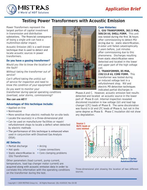
Source 1<br />
NLTC leads or<br />
core related<br />
Application Brief<br />
<strong>Testing</strong> <strong>Power</strong> <strong>Transformers</strong> <strong>with</strong> <strong>Acoustic</strong> <strong>Emission</strong><br />
Case Histories:<br />
1. GSU TRANSFORMER, 362.5 MVA,<br />
500/24 kV, SHELL FORM. This unit<br />
was tested during the first 36 hours<br />
after commissioning to detect PD/<br />
Arcing due to static electrification.<br />
A sister unit failed catastrophically<br />
2 years before, just minutes<br />
after commissioning due to this<br />
phenomena. Discharges resulting<br />
from static electrification were<br />
detected and located in the lower<br />
and upper part of the high voltage<br />
coil.<br />
2. TRANSFORMER, 85 MVA,<br />
230/13.8 kV, CORE FORM. This<br />
transformer was tested during<br />
an induced voltage test in a<br />
refurbishment shop. RIV and<br />
electric PD detection techniques<br />
indicated partial discharges in<br />
Phases A and C. However, acoustic emission test results<br />
detected and located an acoustic source in the lower<br />
part of Phase B coil. Internal inspection revealed<br />
discolored insulation in low voltage (LV) and load tap<br />
changer (LTC) leads of Phase B. The same discoloration<br />
was found in LV and LTC leads of Phase A, but not in the<br />
same degree as Phase B. Phase C insulation did not show<br />
any degradation.<br />
Source 2 Series<br />
Autotransformer<br />
Three-dimensional plot showing the location of two different<br />
sources.
Location of one source in a two-dimensional view.<br />
3. AUTOTRANSFORMER, 243 MVA, 500/230/13.8 kV,<br />
SHELL FORM. This unit was tested twice. The first test<br />
revealed an acoustic source of low amplitude located<br />
in the middle of the high voltage wall. The second test<br />
(one year later) indicated the same source in the same<br />
location, but <strong>with</strong> higher-amplitude and higher-energy<br />
characteristics. An internal inspection performed in that<br />
area indicated that the acoustic activity was generated<br />
by degradation on the no-load tap changer (NLTC) leads.<br />
4. GSU-TRANSFORMER, 784 MVA, 25/500 kV, SHELL<br />
FORM. An AE test was performed because this unit was<br />
gassing heavily. The detection and location of one<br />
low-amplitude source was obtained close to the top of<br />
the core and a low voltage bar. <strong>Acoustic</strong> activity was<br />
particularly intense just before the second group<br />
of pumps operated and diminished a few minutes<br />
after both cooling groups were running. This behavior<br />
indicated the existence of a thermal problem that<br />
corresponded <strong>with</strong> the diagnosis obtained by Dissolved<br />
Gas Analysis (DGA).<br />
5. GSU-TRANSFORMER, 784 MVA, 25/500 kV, SHELL<br />
FORM. Sister unit of the previous case. This unit was<br />
not gassing and no acoustic activity was detected in<br />
the area where the acoustic source was detected for its<br />
sister unit.<br />
Find out more about testing <strong>Transformers</strong> <strong>with</strong> <strong>Acoustic</strong> <strong>Emission</strong>, call (609) 716-4000 today!<br />
Copyright © 2009 <strong>MISTRAS</strong> Group Inc. All Rights Reserved. QSL #104502C Rev 04-08<br />
<strong>Testing</strong> <strong>Power</strong> <strong>Transformers</strong> <strong>with</strong> <strong>Acoustic</strong> <strong>Emission</strong><br />
6. TRANSFORMER, 400 MVA, 500/161/13.8 kV, SHELL<br />
FORM. Several areas of acoustic activity were detected<br />
in this transformer. After filtering extraneous noise and<br />
performing the data analysis, one acoustic source was<br />
located at the bottom of the unit, in the core. Internal<br />
inspection results located the origin of this activity:<br />
overheating in the connection between ground and core<br />
laminations, several inches away from the calculated<br />
location.<br />
Load Current, Current of Pumps # 1 and # 2 , and Temperature.<br />
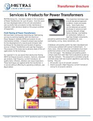
<strong>MISTRAS</strong> Services Division has experience using<br />
acoustic emission for the condition assessment of<br />
power transformers and throughout the years, a<br />
large database has been developed that allows data<br />
comparison between similar designs. <strong>MISTRAS</strong> is also<br />
an active participant on the ongoing EPRI TC project<br />
“Development of a new acoustic emission technique<br />
for the detection and location of gassing sources in<br />
power transformers,” intended to improve upon this<br />
technique.<br />
195 Clarksville Road, Princeton Junction, NJ 08550 USA<br />
Phone: (609) 716-4000 • Fax: (609) 716-0706<br />
Email: sales.services@mistrasgroup.com • www.mistrasgroup.com