ANDT Oil and Gas Brochure - MISTRAS Group, Inc.
ANDT Oil and Gas Brochure - MISTRAS Group, Inc.
ANDT Oil and Gas Brochure - MISTRAS Group, Inc.

You also want an ePaper? Increase the reach of your titles
YUMPU automatically turns print PDFs into web optimized ePapers that Google loves.
G r o u p, I n c.<br />
Advanced NDT<br />
Solutions<br />
<strong>Oil</strong> & <strong>Gas</strong><br />
Products | Systems | Services
1<br />
Centers of Excellence<br />
<strong>MISTRAS</strong> <strong>Group</strong>, <strong>Inc</strong>.<br />
ASSET PROTECTION SOLUTIONS<br />
ADVANCED NDT PRODUCTS, SYSTEMS &<br />
SERVICES FOR THE OIL & GAS INDUSTRY<br />
<strong>MISTRAS</strong> <strong>Group</strong> is the recognized leader in delivering<br />
Advanced Proprietary Products, Systems<br />
<strong>and</strong> Services to the <strong>Oil</strong> & <strong>Gas</strong> industry. Our asset<br />
protection solutions enhance the ability of critical<br />
infrastructure to comply with safety <strong>and</strong> environmental<br />
regulations, extend their life, increase<br />
productivity, minimize repair cost, manage risk <strong>and</strong><br />
most importantly, help avoid catastrophic disaster.<br />
Advanced products, systems <strong>and</strong> services are used<br />
extensively in the <strong>Oil</strong> & <strong>Gas</strong> industry for a high degree<br />
of reliability, which supports improved safety,<br />
drives productivity, increases process availability<br />
<strong>and</strong> helps meet regulatory compliance st<strong>and</strong>ards.<br />
www.mistrasgroup.com | +1.609.716.4150 | sales@mistrasgroup.com<br />
Our advanced technologies <strong>and</strong> techniques are<br />
utilized in <strong>Oil</strong> & <strong>Gas</strong> operations on the following<br />
critical assets to identify potential damage<br />
mechanisms:<br />
• Tanks<br />
• Vessels<br />
• Heat Exchangers <strong>and</strong> Condensers<br />
• Piping<br />
• Rotating Equipment<br />
Our Plant Condition Management Software,<br />
PCMS, is the engine that drives the organization<br />
of inspection data <strong>and</strong> improvements to plant<br />
inspection plans. With the addition of the PCMS<br />
Risk Based Inspection module, <strong>MISTRAS</strong> has the<br />
ability to assess your Mechanical Integrity program<br />
<strong>and</strong> offer recommendations to help you optimize<br />
your inspection spending. This optimization is<br />
based on utilizing the correct inspection technique<br />
for the type of damage associated with your fixed<br />
<strong>and</strong> rotating asset. This customized plan yields increased<br />
reliability of your assets, reduced maintenance<br />
costs, shorter turnaround schedules (based<br />
on minimizing equipment in the turnaround) <strong>and</strong><br />
increased operating income to the facility.<br />
CENTERS OF EXCELLENCE<br />
Throughout North America <strong>and</strong> the world, we<br />
maintain Centers of Excellence (COE) in NDT inspection<br />
technologies. With the use of a sophisticated,<br />
collaborative intranet network, our inspectors <strong>and</strong><br />
engineers employ technologies/software/hardware<br />
that their colleagues may have developed in any one<br />
of our worldwide locations.
TANKS 2<br />
TankPAC<br />
Specific tank related damage mechanisms are:<br />
• Internal <strong>and</strong> external corrosion of roofs,<br />
floors <strong>and</strong> shells<br />
• Weld <strong>and</strong> weld heat affected zone<br />
integrity<br />
• Structural deficiencies (Settlement<br />
Surveys, Out of Roundness, Strapping)<br />
Advanced techniques used to determine the above<br />
damage mechanisms are:<br />
ACOUSTIC EMISSION TANKPAC<br />
<strong>MISTRAS</strong> utilizes a proprietary methodology for<br />
evaluating the condition of tank floors using<br />
Acoustic Emission (AE) while the tank is in service.<br />
An overall condition assessment is performed <strong>and</strong><br />
individual areas of concern are noted to pinpoint<br />
follow up areas to inspect during a subsequent<br />
Out of Service inspection.<br />
TALRUT: ULTRASONIC TANK ANNULAR LONG<br />
RANGE INSPECTION<br />
Utilizing our proprietary LSI system, we are able<br />
to generate semi-quantitative data regarding the<br />
tank floor integrity adjacent to the shell to floor<br />
weld. This inspection technique encompasses<br />
approximately 10” into the tank floor from the<br />
exterior of the tank using an ultrasonic technique<br />
<strong>and</strong> a proprietary algorithm. The annular area of<br />
the tank is critical to the support structure, <strong>and</strong><br />
safe operation of the tank.<br />
TALRUT<br />
www.mistrasgroup.com | +1.609.716.4150 | sales@mistrasgroup.com<br />
TIME-OF-FLIGHT-DIFFRACTION (TOFD)<br />
Ultrasonic TOFD is a rapid survey tool used to<br />
evaluate the shell <strong>and</strong>/or roof weld <strong>and</strong> weld heat<br />
affected zone looking for original fabrication type<br />
defects, or in service corrosion occurring in the<br />
heat affected zone. Follow up phased array inspection<br />
may be required in any area that exhibits<br />
potential damage discovered through the TOFD<br />
inspection.<br />
AUTOMATED ULTRASONIC LSI<br />
The ultrasonic LSI is a rapid erosion/corrosion<br />
scanning tool used for ultrasonic “drops” down<br />
the tank shell or the roof. The device is magnetically<br />
attached to the tank <strong>and</strong> operated remotely.<br />
The amount <strong>and</strong> quality of data is far superior to<br />
ultrasonic thickness readings, in that actual trending<br />
can be visualized as in the case of liquid to air<br />
interface corrosion. In the case of roof readings,<br />
the ability to attach the scanner enhances the<br />
safety of the project, as there is no need to access<br />
the roof by inspection personnel.<br />
C e n t e r s o f E xc e l l e n c e<br />
Tank Inspection<br />
LSI<br />
• Avoid opening tanks <strong>and</strong> eliminate<br />
costs associated with cleaning <strong>and</strong><br />
waste disposal.<br />
• <strong>Inc</strong>rease probability of detecting<br />
corrosion using LSI high speed<br />
corrosion mapping<br />
• Enhance safety using remote crawlers<br />
on roofs.
3<br />
Guided Wave Collar<br />
• Eliminate vessels from turnarounds<br />
using risk based inspection (RBI)<br />
methodology <strong>and</strong> global inspection.<br />
• Identify <strong>and</strong> size defects caused by<br />
unique damage mechanisms like High<br />
Temperature Hydrogen Attack, Stress<br />
Corrosion Cracking, <strong>and</strong> more.<br />
• Perform “On-Line” Monitoring of<br />
suspect assets to ensure continued safe<br />
operation.<br />
VESSELS<br />
TOFD<br />
Vessel service leads to the following issues:<br />
• Internal <strong>and</strong> External Erosion/Corrosion<br />
• Cracking<br />
• Weld <strong>and</strong> weld heat affected zone issues<br />
• Metallurgical damage<br />
Advanced techniques used to determine the above<br />
damage mechanisms are:<br />
AE MONPAC PLUS INSPECTION<br />
MonPAC Plus is a technology package developed<br />
by <strong>MISTRAS</strong> that allows owners to inspect a pressure<br />
vessel to determine the relative condition of<br />
the asset while the asset is still in service. Potential<br />
anomalies are detected <strong>and</strong> located for use in<br />
follow up inspections. The use of MonPAC Plus<br />
greatly reduces the need to further perform costly<br />
out of service inspections of vessels that show no<br />
signs of degradation.<br />
ROPE ACCESS<br />
Certified rope access technicians work in difficult<br />
or inaccessible areas efficiently without the need<br />
for scaffolding, cranes, or mobile work platforms.<br />
Using rope access for inspection <strong>and</strong> maintenance<br />
activities generates significant cost-savings for asset<br />
owners, especially where traditional access<br />
methods comprise a major portion of the overall<br />
project budget.<br />
AUTOMATED ULTRASONIC LSI<br />
See Page 5, Piping, for more information.<br />
www.mistrasgroup.com | +1.609.716.4150 | sales@mistrasgroup.com<br />
PULSED EDDY CURRENT (PEC)<br />
PEC technology is an inspection technique for<br />
measuring the thickness of steel objects without<br />
direct contact to the steel surface. The electromagnetic<br />
test uses a pancake probe to identify<br />
general corrosion through insulation or concrete<br />
surfaces by introducing an electric current into<br />
the transmitter coil, magnetizing the steel <strong>and</strong><br />
measuring wall thickness. PEC is ideal for surveying<br />
large sections of piping or pressure vessels to<br />
detect areas that have been affected by moisture<br />
trapped under insulation causing corrosion of<br />
the asset being inspected. Use PEC when other<br />
NDT techniques may be limited due to the larger<br />
diameters encountered when inspecting insulated<br />
vessels.<br />
PHASED ARRAY<br />
See Page 5-6, Piping, for more information.<br />
ULTRASONIC P-SCAN<br />
Different forms of cracking such as fatigue, creep,<br />
HIC, SOHIC <strong>and</strong> various forms of embrittlement,<br />
may occur depending on the process in which<br />
the equipment is operating. These begin as microscopic<br />
damage <strong>and</strong> can occur along the grain<br />
boundaries of the parent material or the weld<br />
heat affected zones. The P-Scan is used to accurately<br />
detect <strong>and</strong> size these mechanisms in its<br />
early stages of damage formation, while creating<br />
three dimensional views of the weld that enables<br />
the operator to better visualize its position.<br />
TIME OF FLIGHT DIFFRACTION (TOFD)<br />
TOFD is utilized as a quick survey tool of welds<br />
<strong>and</strong> weld heat affected zones in pressure vessels<br />
looking for the presence of welding fabrication<br />
defects or screening for cracking. It is an excellent<br />
tool for providing accurate through-wall depths of<br />
existing cracks.
HEAT EXCHANGERS & CONDENSERS<br />
A variety of tube inspection techniques are used<br />
for bundle inspections. The choice of technique<br />
depends on the tube material type. <strong>MISTRAS</strong><br />
technicians are cross trained on IRIS, Remote Field<br />
Eddy Current, Near Field Eddy Current <strong>and</strong> st<strong>and</strong>ard<br />
Eddy Current techniques <strong>and</strong> use the same<br />
operating system to achieve these results. This<br />
“Cross Training” allows us to minimize the amount<br />
of technicians we need to deploy to your project,<br />
ultimately saving inspection dollars.<br />
Heat Exchangers <strong>and</strong> Condensers are subject to<br />
various issues related to the tube bundles such as:<br />
• Internal <strong>and</strong> External Pitting <strong>and</strong><br />
Corrosion <strong>and</strong> Erosion<br />
• Cracking (SCC, Fatigue, Thermal, Vibration)<br />
• Mechanical damage (Inlet Erosion,<br />
Baffle Fretting, Freeze Bulges, Tool Gouges)<br />
A variety of advanced techniques are used for<br />
bundle inspections, such as:<br />
REMOTE FIELD TESTING (RFT)<br />
Carbon steel tube bundles are inspected using<br />
RFT. The RFT technique utilizes the same platform<br />
as our st<strong>and</strong>ard ET inspections which does not<br />
require tubes to be as clean as other techniques.<br />
Our professional inspectors are cross trained to<br />
provide both ET <strong>and</strong> RFT while on site.<br />
www.mistrasgroup.com | +1.609.716.4150 | sales@mistrasgroup.com<br />
NFT Sample Damage 3D Reporting<br />
NEAR FIELD TESTING (NFT)<br />
NFT is used for inspecting fin fan (air coolers)<br />
designed tube bundles. Also available in our<br />
st<strong>and</strong>ard ET equipment platform, NFT is a very<br />
reliable technique to determine ID anomalies -<br />
such as inlet erosion, corrosion, <strong>and</strong> pitting - that<br />
normally occur during service in this previously<br />
difficult to inspect tube design.<br />
INTERNAL ROTARY INSPECTION SYSTEM (IRIS)<br />
IRIS uses ultrasonic technology with a rotating<br />
transducer to deliver quantifiable data on the ID<br />
or OD damage to tubes. Primarily used as a prove<br />
up tool, IRIS requires tubes to be cleaner than other<br />
tube inspection techniques <strong>and</strong> scan speeds to<br />
be slightly slower. Also available in our ET equipment<br />
platform, all IRIS tube data is presented in a<br />
C-Scan <strong>and</strong> B-Scan profile & archived for playback.<br />
EDDY CURRENT (ET)<br />
ET is the predominant inspection technique for the<br />
alloy tubes. ET does not require the tubes to be<br />
as clean as some other techniques <strong>and</strong> is relatively<br />
fast compared to more quantitative techniques<br />
like IRIS. <strong>MISTRAS</strong>’ tube inspection specialists<br />
utilize the latest ET technology along with an<br />
electronic reporting format that allows for quick<br />
analysis <strong>and</strong> generation of tube sheet drawings<br />
<strong>and</strong> results in an easy to read template.<br />
3-D REPORTING<br />
<strong>MISTRAS</strong> tube inspection reports are revolutionary<br />
in their ability to provide defect data down the<br />
length of the tube. The tube data allows owners<br />
the increased ability to determine the root cause<br />
of tube degradation <strong>and</strong> potentially allows them<br />
to avoid the problem in the future through operating<br />
procedural changes or change in tube material<br />
choice during bundle repair. All tube inspection<br />
data is left on site in order to speed the process of<br />
getting the exchanger into production as quickly<br />
as possible. Tube inspection specialists review all<br />
on-site data & provide the final report to the client<br />
within 72 hours of the completion of the project.<br />
4
5<br />
Touch Point Corrosion<br />
• <strong>Inc</strong>rease probability of detection<br />
utilizing comprehensive global<br />
inspection methods<br />
• Apply appropriate ultrasonic<br />
techniques to various cracking<br />
mechanisms<br />
• Perform online monitoring to ensure<br />
safe operation of at-risk piping<br />
PIPING<br />
Guided Wave Weldstar<br />
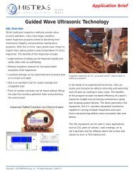
The goal of piping system inspection is to increase<br />
the reliability of the system by increasing the<br />
mean run time to failure. In order to achieve<br />
this, an owner must utilize the proper inspection<br />
technique based on the associated damage<br />
mechanism. Utilizing point to point ultrasonic<br />
thickness readings is relatively useless if the owner<br />
is concerned about localized corrosion. Proprietary<br />
techniques such as a Touch Point Corrosion<br />
ultrasonic methodology <strong>and</strong> On-line monitoring of<br />
suspect lines are available through <strong>MISTRAS</strong>.<br />
In addition to damage mechanisms, accessibility<br />
to the piping becomes a determining factor in<br />
the choice of inspection tools. For instance, for<br />
piping systems at height, <strong>MISTRAS</strong> utilizes rope<br />
access technicians to aid in the inspection. These<br />
individuals are capable of performing any inspection<br />
from ropes that we perform from the ground<br />
including Guided Wave, Erosion Corrosion scanning,<br />
PEC Tool or Pocket UT.<br />
A variety of potential damage mechanisms need to<br />
be considered when inspecting piping, such as:<br />
• External Erosion Corrosion<br />
• Internal Erosion Corrosion<br />
• Cracking<br />
• Mechanical Damage<br />
• Metallurgical Issues<br />
• Weld Quality<br />
• Leaking Valves<br />
Advanced techniques used to determine the above<br />
damage mechanisms are:<br />
www.mistrasgroup.com | +1.609.716.4150 | sales@mistrasgroup.com<br />
AUTOMATED ULTRASONIC LSI<br />
Our LSI system performs ultrasonic surveys at 25<br />
inches per second, allowing us to inspect large areas<br />
of piping very quickly. Our UTIA software allows<br />
the operator enhanced flexibility to analyze<br />
the data for optimum visual correlation with the<br />
A-B <strong>and</strong> C-Scans. Stitching multiple scans together<br />
allows an overview of the entire piping system.<br />
PHASED ARRAY<br />
Phased array is a versatile tool that electronically<br />
produces multiple wave modes <strong>and</strong> angles<br />
electronically in nanoseconds. This is an excellent<br />
choice for detecting cracking caused by a host of<br />
other damage mechanisms <strong>and</strong> is highly beneficial<br />
in providing accurate sizing data for use in Fitness<br />
for Service calculations. Phased Array may also<br />
be used to perform final acceptance of code quality<br />
welding per ASME code requirement in lieu of<br />
radiography. This application results in substantial<br />
savings to the owners by eliminating the restricted<br />
areas required when performing radiography.<br />
GUIDED ULTRASONIC LONG RANGE<br />
Guided wave technology utilizes torsional <strong>and</strong><br />
longitudinal waves to inspect large sections of<br />
piping from one location. Guided wave is used<br />
as a screening tool, in most cases, on insulated<br />
piping as well as buried piping, wharf <strong>and</strong> jetty<br />
piping, offshore piping in splash zones <strong>and</strong> in traditionally<br />
inaccessible areas. It is also used as part<br />
of a PMI Retrofit program to locate piping welds<br />
between attachments.
Phased Array P-Scan & Computed RT Valve Testing <strong>and</strong> Monitoring<br />
Guided wave can detect both internal <strong>and</strong> external<br />
corrosion or other significant defects <strong>and</strong> locate<br />
them along the pipe. <strong>MISTRAS</strong> uses the latest<br />
guided wave technology called the G3 or the third<br />
generation system which supplies better accuracy<br />
than previous technology. In addition, Permanently<br />
Installed Sensors (PIMS) can be installed in various<br />
locations, including buried piping applications,<br />
to monitor areas that are suspect without having<br />
to dig trenches for subsequent inspections.<br />
ULTRASONIC P-SCAN<br />
Whether looking for a more thorough tool to<br />
evaluate the quality of a weld, or for environmentally<br />
assisted cracking such as fatigue, stress<br />
corrosion cracking <strong>and</strong> others, the P-Scan system is<br />
more than capable of imaging these flaws in a way<br />
to better evaluate, characterize <strong>and</strong> size them.<br />
COMPUTED RT<br />
Computed Radiography is especially effective when<br />
used with profile radiographic techniques when<br />
looking for quantitative & qualitative data for piping.<br />
This technique enables evaluation of large sections<br />
of piping to determine erosion/corrosion rates<br />
in this section vs. the relatively small areas obtained<br />
using point to point ultrasonic thickness exams. In<br />
addition, computed radiography may be used during<br />
ASME or other code welding processes in lieu<br />
of traditional radiography. The combination of computed<br />
radiography <strong>and</strong> a Selenium 65 radiographic<br />
source enables a dramatic reduction of radiation in<br />
boundary areas. This reduction allows welders to<br />
work in close proximity to the inspection area.<br />
www.mistrasgroup.com | +1.609.716.4150 | sales@mistrasgroup.com<br />
ACOUSTIC EMISSION (AE)<br />
Leaking valves are a common problem with results<br />
showing that 5 to 10 percent of the valves in <strong>Oil</strong><br />
<strong>and</strong> <strong>Gas</strong> plants leak. More importantly, it was<br />
determined that just 1 to 2 percent of the valves<br />
accounted for approximately 70 percent of the<br />
losses. Valve leak detection works by detecting<br />
the “noise” produced as the medium passes<br />
through the valve as “turbulent” flow. Turbulent<br />
flow creates a signal with frequency components<br />
well over 100 KHz. This allows the use of high frequency<br />
acoustic emission sensors with frequencies<br />
above the vibration <strong>and</strong> background noise level<br />
of the plant. This characteristic makes reliable<br />
detection <strong>and</strong> quantification of leaks possible. In<br />
addition to being able to determine if a valve is<br />
leaking, our proprietary algorithms allow us to<br />
“quantify” the amount of the leak.<br />
ADVANCED ULTRASONIC BACKSCATTER<br />
TECHNIQUE (AUBT)<br />
Certain low alloy carbon steel material operating<br />
at temperatures <strong>and</strong> hydrogen partial pressures<br />
above the Nelson Curve, can be suspect<br />
to decarburization as well as microfissuring <strong>and</strong><br />
macrocracking, which can result in catastrophic<br />
consequences. With the use of proven ultrasonic<br />
technologies evaluating frequency dependence,<br />
velocities, <strong>and</strong> several other factors, we are able to<br />
help determine which pieces have been affected<br />
by High Temperature Hydrogen Attack (HTHA).<br />
PULSED EDDY CURRENT (PEC)<br />
See Page 3, Vessels, for more information.<br />
• Save millions of dollars in lost<br />
production cost<br />
• Qualitative <strong>and</strong> quantitative<br />
measurement capabilities<br />
6
7<br />
• Maximize reliability <strong>and</strong> availability of<br />
rotating assets<br />
• Pre warranty expiration inspection<br />
• Facility routine prevention<br />
maintenance<br />
ROTATING EQUIPMENT<br />
Predictive Maintenance (PdM) <strong>and</strong> Proactive<br />
Maintenance (ProAM) technologies are utilized on<br />
the following assets:<br />
Rotating Equipment<br />
• Motors<br />
• Pumps<br />
• Compressors<br />
• Gearboxes<br />
• Turbines<br />
• Fans<br />
Electrical Equipment<br />
• Transformers<br />
• Motor Control Centers<br />
• Switch Gear<br />
Fixed Equipment<br />
• Steam Traps<br />
• Compressed Air lines<br />
A variety of potential damage mechanisms need to<br />
be considered when applying PdM/ProAM<br />
technologies such as:<br />
• Bearing Damage<br />
• Gear Damage<br />
• Coupling type <strong>and</strong> condition<br />
• Lubrication - Lack of <strong>and</strong><br />
Contamination<br />
• Alignment of coupled shafts<br />
• Balance or rotors<br />
• Leaks<br />
• Electrical Discharge<br />
Advanced techniques used to detect the various<br />
issues listed above are:<br />
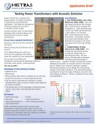
VIBRATION ANALYSIS<br />
Vibration Analysis technology can be applied to all<br />
rotating equipment on site. Utilizing this technology<br />
can provide the site with immediate insight into<br />
the health of the rotating components. It can be<br />
used to isolate the location of damage to rotating<br />
components, as well as help determine the<br />
www.mistrasgroup.com | +1.609.716.4150 | sales@mistrasgroup.com<br />
severity of damage. All of the potential damage<br />
mechanisms listed above <strong>and</strong> more can be identified,<br />
trended <strong>and</strong> potentially eliminated by effectively<br />
implemented PdM programs using vibration<br />
analysis. Vibration is applied to equipment in<br />
service so there is no impact to production.<br />
<strong>MISTRAS</strong> Services can also provide this technology<br />
in hazardous environments by the use of<br />
Intrinsically Safe (IS) equipment.<br />
OIL ANALYSIS<br />
Lube oil is critical to the health of any rotating<br />
piece of equipment. Underst<strong>and</strong>ing the condition<br />
of the lubrication (oil/grease) in rotating<br />
equipment allows operations <strong>and</strong> maintenance to<br />
effectively plan lubrication PMs. Due to sample<br />
size equipment, isolation <strong>and</strong> shut down are not<br />
required. <strong>MISTRAS</strong> uses independent lab analysis<br />
<strong>and</strong> correlates the data with other PdM technologies<br />
in a unified database. Applying multiple technologies<br />
provides our customers the confidence<br />
with secondary <strong>and</strong> tertiary confirmation.<br />
AIRBORNE ULTRASONICS (AU)<br />
Airborne Ultrasonics is used in several applications<br />
to monitor bearings, electrical discharge,<br />
air leaks <strong>and</strong> effective management of lube oil<br />
programs. Some assets are inaccessible to vibration<br />
probes, however airborne ultrasonics can<br />
be applied effectively. Airborne Ultrasonics, used<br />
in combination with Thermography scans, has<br />
provided additional accuracy <strong>and</strong> safety to electrical<br />
system inspections. PdM programs have saved<br />
hundreds of thous<strong>and</strong>s of dollars annually by using<br />
UT to find steam <strong>and</strong> compressed air leaks.<br />
INFRARED INSPECTION (IR)<br />
Thermography, initially considered an electrical<br />
inspection technique, can be applied to rotating<br />
<strong>and</strong> fixed assets as well. Used in electrical inspection,<br />
it can identify differences in temperatures of<br />
connections, fuses, transformers, switchgear, etc.
Vibration Analysis<br />
Combining IR <strong>and</strong> AU is essential to any comprehensive<br />
PdM program, <strong>and</strong> applying AU provides<br />
additional levels of safety during electrical inspections.<br />
Electrical discharge, also known as carona,<br />
can only be detected using AU, <strong>and</strong> the effects of<br />
carona can be found with visual <strong>and</strong> IR inspection.<br />
MOTOR CURRENT SIGNATURE ANALYSIS (MCSA)<br />
Our periodic MCSA program detects motor faults<br />
such as broken/cracked bars, as well as problems<br />
with the high resistance joints on any AC induction<br />
motor. Our advanced approach helps to identify<br />
the probability <strong>and</strong> severity of these faults, while<br />
trending values to allow ample time for scheduling<br />
repairs.<br />
ACOUSTIC EMISSION (AE)<br />
Acoustic Emission is the term used when defects<br />
in metals, plastics <strong>and</strong> other materials rapidly<br />
release energy when subjected to mechanical<br />
loading. The energy propagates in the form of high<br />
frequency stress waves <strong>and</strong> these types of oscillations<br />
are picked up by AE sensors on the surface of<br />
the specimen <strong>and</strong> converted to electrical signals,<br />
so-called bursts. The AE analysis is the characterization<br />
of the bursts according to intensity <strong>and</strong><br />
frequency content. Analyzing bursts from several<br />
sensors at well placed positions on the asset allows<br />
for determination of the location of the AE<br />
source(s) on the asset.<br />
Thermography<br />
www.mistrasgroup.com | +1.609.716.4150 | sales@mistrasgroup.com<br />
LASER ALIGNMENT<br />
Precision laser alignment of coupled machinery is<br />
critical to maximizing the performance <strong>and</strong> availability<br />
of machine trains. Misaligned machines are<br />
more likely to experience seal <strong>and</strong> bearing failures<br />
<strong>and</strong> can result in reduced product quality <strong>and</strong><br />
ultimately production shutdowns. Misalignment is<br />
most frequently detected during routine vibration<br />
data collection.<br />
DYNAMIC ROTOR BALANCE<br />
Dynamic balancing extends your equipment’s life<br />
by eliminating vibration that destroys mechanical<br />
components. <strong>MISTRAS</strong> can balance rotors in their<br />
own bearings on site, utilizing portable equipment.<br />
Precision On-site balancing drastically reduces<br />
downtime <strong>and</strong> repair costs, while increasing<br />
your productivity. Our staff brings extensive<br />
balancing experience to your plant for virtually<br />
every type, shape <strong>and</strong> size of rotor.<br />
8
9<br />
VALUE ADDED SERVICES PACKAGES (VASP)<br />
Permanently Installed Monitor (PIMS) LSI Results<br />
Our Value Added Services Packages are<br />
encompassed in our Asset Integrity<br />
Management (AIMS) methodology. The AIMS approach<br />
combines traditional NDT with Advanced<br />
NDT, Engineering analysis <strong>and</strong> our robust PCMS<br />
software package, to yield cost effective solutions<br />
to current issues with regards to fixed <strong>and</strong> rotating<br />
equipment in the <strong>Oil</strong> <strong>and</strong> <strong>Gas</strong> industry. Most<br />
plants utilize traditional inspection techniques to<br />
inspect the assets that are covered in the plant’s<br />
mechanical integrity program to prioritize their<br />
fixed assets based on time <strong>and</strong> interval based<br />
programs, with the data residing in an Inspection<br />
Data Management System (IDMS). In our case, the<br />
data is housed in our Plant Condition Monitoring<br />
Software (PCMS).<br />
Advanced techniques are utilized as st<strong>and</strong> alone<br />
technology, part of a technology solution to combine<br />
engineered pre-project planning with Risk<br />
Based Inspection (RBI) techniques (also available<br />
in PCMS) or a combination of multiple advanced<br />
techniques with more definitive quantitative<br />
inspection techniques used to “prove up” our<br />
holistic approach(es).<br />
Most of these technologies are implemented while<br />
the asset is still in service, thereby eliminating<br />
or greatly reducing the cleaning, environmental<br />
remediation <strong>and</strong> disposal costs required to inspect<br />
the asset while it is out of service. This also<br />
reduces the unanticipated discovery <strong>and</strong> associated<br />
inspection <strong>and</strong> repair cost when the assets<br />
are opened. In all cases, <strong>MISTRAS</strong> personnel can<br />
www.mistrasgroup.com | +1.609.716.4150 | sales@mistrasgroup.com<br />
not only provide the inspection technology that is<br />
appropriate based on anticipated damage mechanism,<br />
but also house the data within PCMS <strong>and</strong><br />
evaluate the data by performing code approved<br />
engineering calculations that yield accurate<br />
remaining useful life, <strong>and</strong> run, repair or replacement<br />
decisions.<br />
An additional benefit of using <strong>MISTRAS</strong> is our ability<br />
to provide on-line health monitoring on high<br />
risk critical assets to allow plant operators to continue<br />
to operate an asset that exhibits high risk of<br />
potential failure until the plant can implement a<br />
cost effective alternative plan, such as the repair<br />
or replacement of the asset in question.<br />
CASE STUDY: EXTERNAL CORROSION OF ABOVE<br />
GROUND PROCESS PIPING<br />
External corrosion in above ground piping can occur<br />
due to a variety of issues including corrosion<br />
under insulation, Touch Point Corrosion (TPC) or<br />
Point of Contact corrosion. <strong>MISTRAS</strong> provides a<br />
holistic program to address these two concerns as<br />
well as addressing other concerns such as Retro<br />
Positive Material Identification to determine if the<br />
proper weld filler material was used during piping<br />
construction (a common failure in the <strong>Oil</strong> <strong>and</strong> <strong>Gas</strong><br />
industry).<br />
As illustrated in our Asset Integrity Management<br />
approach our external corrosion program follows<br />
a regimented, consistent method that prescribes<br />
the proper technologies to identify potential dam-
Finite Element Analysis Risk Based Inspection Rope Access<br />
age as well as provide operating decisions to the<br />
plant owners regarding the ability to run, repair<br />
or replace the asset. Our st<strong>and</strong>ardized corrosion<br />
program utilizes external visual inspections,<br />
performed by an API 570 inspector, to verify piping<br />
isometrics or correct any “field” deviations from<br />
the isometric drawings. In addition, the inspector<br />
identifies potential problem areas. Corrosion<br />
monitoring locations (CML’s) are assigned based<br />
on API 570 criteria along with good engineering<br />
practice. Next, thickness measurements are obtained<br />
using a combination of ultrasonic thickness<br />
readings, ultrasonic corrosion surveys or traditional/computed<br />
profile radiography. All measurements<br />
are then populated into our PCMS<br />
database.<br />
In the case of Corrosion under Insulation, Touch<br />
Point Corrosion or other more sophisticated programs,<br />
the following steps are performed:<br />
• Identify piping systems of interest<br />
• Walk down piping systems while reviewing,<br />
verifying <strong>and</strong> editing all P&ID <strong>and</strong> Isometric<br />
drawings normally performed by an API 570<br />
visual inspector<br />
• Enter drawings into PCMS<br />
• Globally inspect the piping systems using Guided<br />
Ultrasonic Long Range inspection. Indicate<br />
where potential damage is occurring <strong>and</strong> if part<br />
of a PMI retrofit program, transcribe weld line<br />
details to updated P&ID’s <strong>and</strong> ISO’s. If GUL is<br />
being used for Touch Point Corrosion concerns,<br />
indicate those TPC’s that exhibit potential damage<br />
<strong>and</strong> note on drawings.<br />
www.mistrasgroup.com | +1.609.716.4150 | sales@mistrasgroup.com<br />
• Follow up qualitative or semi-qualitative inspections.<br />
For TPC concerns, utilize <strong>MISTRAS</strong>’<br />
proprietary Pocket UT system for touch point<br />
corrosion. Results are expressed in percentage<br />
wall loss within a range. For weld defects<br />
related to PMI concerns, utilize phased array<br />
<strong>and</strong>/or P-Scan ultrasonic technology. For various<br />
process induced anomalies (HIC, SOHIC etc.)<br />
utilize a combination of Time of Flight Diffraction<br />
<strong>and</strong> P-Scan.<br />
• Indicate amount of pipe wall loss, location of<br />
damage <strong>and</strong> extent of damage using<br />
LSI/Pocket UT C-Scan mapping<br />
• Evaluate extent of damage using Fitness for<br />
Service calculations. FFS results will indicate<br />
future operational decisions such as repair,<br />
replace or run <strong>and</strong> monitor<br />
• On-line monitoring using Acoustic Emission,<br />
Vibration, Strain Gauging or other On-line<br />
techniques using <strong>MISTRAS</strong>’ Sensor Highway II<br />
system tied into the plant’s control room or<br />
remotely monitored from <strong>MISTRAS</strong> corporate<br />
office<br />
• Upload all data into PCMS<br />
• Reinspect using st<strong>and</strong>ard API calculations<br />
imbedded in PCMS software or utilize API 580<br />
based RBI calculations for reinspection data also<br />
imbedded in PCMS<br />
• Eliminate scaffolding cost<br />
• Refiner saved $945,000 in a 3 month<br />
period avoiding scaffolding<br />
• Use PCMS RBI to prioritize<br />
appropriate NDT inspection techniques.<br />
10
G r o u p, I n c.<br />
One<br />
Source<br />
for<br />
Asset<br />
Protection<br />
Solutions<br />
CORPORATE HEADQUARTERS<br />
195 Clarksville Road<br />
Princeton Junction, NJ 08550<br />
United States<br />
TEL: +1.609.716.4150<br />
FAX: +1.609.716.4145<br />
E-MAIL: sales@mistrasgroup.com<br />
WEB: www.mistrasgroup.com<br />
UNITED STATES<br />
MIDWEST REGION<br />
TEL: +1.630.230.3400<br />
GULF REGION<br />
TEL: +1.281.478.1600<br />
NORTHEAST REGION<br />
TEL: +1.610.497.0400<br />
MOUNTAIN REGION<br />
TEL: +1.303.393.9689<br />
WEST REGION<br />
TEL: +1.562.597.3932<br />
INTERNATIONAL<br />
CANADA<br />
TEL: +1.403.556.1350<br />
CHINA<br />
TEL: +86.10.5877.3631<br />
FRANCE<br />
TEL: +33.149.826.040<br />
GERMANY<br />
TEL: +49.40 2000.4025<br />
GREECE<br />
TEL: +30.210.2846.801<br />
HOLLAND<br />
TEL: +31.10.245.0325<br />
INDIA<br />
TEL: +91.22.2586.2444<br />
MID-ATLANTIC REGION<br />
TEL: +1.804.745.5830<br />
<strong>MISTRAS</strong>-IMPRO<br />
TEL: +1.661.829.1192<br />
SOUTHEAST REGION<br />
TEL: +1.704.291.2360<br />
PRODUCTS & SYSTEMS<br />
TEL: +1.609.716.4000<br />
SERVICES<br />
TEL: +1.609.716.4150<br />
JAPAN<br />
TEL: +81.33.498.3570<br />
MALAYSIA<br />
TEL: +60.9.517.3788<br />
MIDDLE EAST<br />
TEL: +973.17.729.356<br />
RUSSIA<br />
TEL: +7.495.789.4549<br />
SCANDINAVIA<br />
TEL: +46.031.252040<br />
SOUTH AMERICA<br />
TEL: +55.11.3082.5111<br />
UNITED KINGDOM<br />
TEL:+44.(0)195.423.1612<br />
Copyright © 2011 <strong>MISTRAS</strong> <strong>Group</strong>, <strong>Inc</strong>. All Rights Reserved.<br />
Specifications <strong>and</strong> features subject to change without notice.<br />
#100B-11100-02<br />
MG<br />
LISTED<br />
Scan this 2D<br />
Code with your<br />
smartphone’s<br />
barcode reader<br />
for more O&G<br />
information.