Outdoor Unit CU-2E18NBK TABLE OF CONTENTS - Panasonic
Outdoor Unit CU-2E18NBK TABLE OF CONTENTS - Panasonic
Outdoor Unit CU-2E18NBK TABLE OF CONTENTS - Panasonic

You also want an ePaper? Increase the reach of your titles
YUMPU automatically turns print PDFs into web optimized ePapers that Google loves.
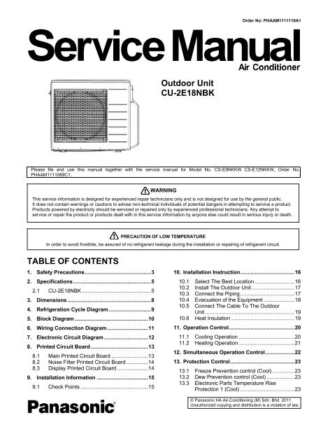
<strong>Outdoor</strong> <strong>Unit</strong><br />
<strong>CU</strong>-<strong>2E18NBK</strong><br />
Order No: PHAAM1111119A1<br />
Please file and use this manual together with the service manual for Model No. CS-E9NKKW CS-E12NKKW, Order No.<br />
PHAAM1111089C1.<br />
<strong>TABLE</strong> <strong>OF</strong> <strong>CONTENTS</strong><br />
1. Safety Precautions.............................................3<br />
2. Specifications.....................................................5<br />
2.1 <strong>CU</strong>-<strong>2E18NBK</strong> ...............................................5<br />
3. Dimensions.........................................................8<br />
4. Refrigeration Cycle Diagram.............................9<br />
5. Block Diagram ..................................................10<br />
6. Wiring Connection Diagram............................11<br />
7. Electronic Circuit Diagram ..............................12<br />
8. Printed Circuit Board .......................................13<br />
8.1 Main Printed Circuit Board .........................13<br />
8.2 Noise Filter Printed Circuit Board...............14<br />
8.3 Display Printed Circuit Board .....................14<br />
9. Installation Information ...................................15<br />
9.1 Check Points ..............................................15<br />
WARNING<br />
This service information is designed for experienced repair technicians only and is not designed for use by the general public.<br />
It does not contain warnings or cautions to advise non-technical individuals of potential dangers in attempting to service a product.<br />
Products powered by electricity should be serviced or repaired only by experienced professional technicians. Any attempt to<br />
service or repair the product or products dealt with in this service information by anyone else could result in serious injury or death.<br />
PRECAUTION <strong>OF</strong> LOW TEMPERATURE<br />
In order to avoid frostbite, be assured of no refrigerant leakage during the installation or repairing of refrigerant circuit.<br />
10. Installation Instruction.....................................16<br />
10.1 Select The Best Location ...........................16<br />
10.2 Install The <strong>Outdoor</strong> <strong>Unit</strong> .............................17<br />
10.3 Connect the Piping.....................................17<br />
10.4 Evacuation of the Equipment .....................18<br />
10.5 Connect The Cable To The <strong>Outdoor</strong><br />
<strong>Unit</strong> .............................................................19<br />
10.6 Heat Insulation ...........................................19<br />
11. Operation Control.............................................20<br />
11.1 Cooling Operation ......................................20<br />
11.2 Heating Operation ......................................21<br />
12. Simultaneous Operation Control....................22<br />
13. Protection Control............................................23<br />
13.1 Freeze Prevention control (Cool) ...............23<br />
13.2 Dew Prevention control (Cool) ...................23<br />
13.3 Electronic Parts Temperature Rise<br />
Protection 1 (Cool) .....................................23<br />
© <strong>Panasonic</strong> HA Air-Conditioning (M) Sdn. Bhd. 2011.<br />
Unauthorized copying and distribution is a violation of law.
13.4 Electronic Parts Temperature Rise<br />
Protection 2 (Cool)......................................23<br />
13.5 Cooling overload control (Cool)..................24<br />
13.6 Heating overload control (Heat) .................24<br />
13.7 Extreme Low Temperature Compressor low<br />
pressure protection control (Heat)..............24<br />
13.8 Deice Control..............................................25<br />
13.9 Time Delay Safety Control<br />
(Restart Control) .........................................25<br />
13.10 30 seconds Force Operation ......................25<br />
13.11 Total Current Control..................................25<br />
13.12 IPM (power transistor) Protection<br />
Control ........................................................25<br />
13.13 Compressor Protection Control<br />
(Gas leak detection control 1) ....................26<br />
13.14 Compressor Protection Control<br />
(Gas leak detection control 2) ....................26<br />
13.15 Valve close detection control......................26<br />
13.16 Compressor discharge high pressure<br />
protection control ........................................26<br />
14. Servicing Mode.................................................27<br />
14.1 <strong>CU</strong>-<strong>2E18NBK</strong> .............................................27<br />
15. Troubleshooting Guide....................................29<br />
15.1 Self Diagnosis Function..............................29<br />
16. Disassembly and Assembly Instructions ......32<br />
16.1 <strong>Outdoor</strong> <strong>Unit</strong> Removal Procedure ..............32<br />
17. Technical Data ..................................................35<br />
17.1 Operation Characteristics...........................35<br />
18. Exploded View and Replacement Parts<br />
List .....................................................................55<br />
2
1. Safety Precautions<br />
� Read the following “SAFETY PRECAUTIONS” carefully before perform any servicing.<br />
� Electrical work must be installed or serviced by a licensed electrician. Be sure to use the correct rating of the<br />
power plug and main circuit for the model installed.<br />
� The caution items stated here must be followed because these important contents are related to safety. The<br />
meaning of each indication used is as below. Incorrect installation or servicing due to ignoring of the instruction<br />
will cause harm or damage, and the seriousness is classified by the following indications.<br />
WARNING<br />
CAUTION<br />
This indication shows the possibility of causing death or serious injury.<br />
This indication shows the possibility of causing injury or damage to properties.<br />
� The items to be followed are classified by the symbols:<br />
This symbol denotes item that is PROHIBITED from doing.<br />
� Carry out test run to confirm that no abnormality occurs after the servicing. Then, explain to user the operation,<br />
care and maintenance as stated in instructions. Please remind the customer to keep the operating instructions for<br />
future reference.<br />
1. Do not modify the machine, part, material during repairing service.<br />
WARNING<br />
2. If wiring unit is supplied as repairing part, do not repair or connect the wire even only partial wire break. Exchange the whole wiring unit.<br />
3. Do not wrench the fasten terminal. Pull it out or insert it straightly.<br />
4. Engage dealer or specialist for installation and servicing. If installation or servicing done by the user is defective, it will cause water<br />
leakage, electrical shock or fire.<br />
5. Install according to this installation instructions strictly. If installation is defective, it will cause water leakage, electric shock or fire.<br />
6. Use the attached accessories parts and specified parts for installation and servicing. Otherwise, it will cause the set to fall, water leakage,<br />
fire or electrical shock.<br />
7. Install at a strong and firm location which is able to withstand the set’s weight. If the strength is not enough or installation is not properly done,<br />
the set will drop and cause injury.<br />
8. For electrical work, follow the local national wiring standard, regulation and the installation instruction. An independent circuit and single outlet<br />
must be used. If electrical circuit capacity is not enough or defect found in electrical work, it will cause electrical shock or fire.<br />
9. This equipment is strongly recommended to install with Earth Leakage Circuit Breaker (ELCB) or Residual Current Device (RCD).<br />
Otherwise, it may cause electrical shock and fire in case equipment breakdown or insulation breakdown.<br />
10. Do not use joint cable for indoor/outdoor connection cable. Use the specified indoor/outdoor connection cable, refer to installation<br />
instruction CONNECT THE CABLE TO THE INDOOR UNIT and connect tightly for indoor/outdoor connection. Clamp the cable so that no<br />
external force will be acted on the terminal. If connecting or fixing is not perfect, it will cause heat up or fire at the connection.<br />
11. Wire routing must be properly arranged so that control board cover is fixed properly. If control board cover is not fixed perfectly, it will cause<br />
heat-up or fire at the connection point of terminal, fire or electrical shock.<br />
12. When install or relocate air conditioner, do not let any substance other than the specified refrigerant, eg. air etc. mix into refrigeration cycle<br />
(piping). (Mixing of air etc. will cause abnormal high pressure in refrigeration cycle and result in explosion, injury etc.).<br />
13. Do not install outdoor unit near handrail of veranda. When installing air-conditioner unit at veranda of high rise building, child may climb up to<br />
outdoor unit and cross over the handrail and causing accident.<br />
14. This equipment must be properly earthed. Earth line must not be connected to gas pipe, water pipe, earth of lightning rod and<br />
telephone. Otherwise, it may cause electric shock in case equipment breakdown or insulation breakdown.<br />
15. Keep away from small children, the thin film may cling to nose and mouth and prevent breathing.<br />
16. Do not use unspecified cord, modified cord, joint cord or extension cord for power supply cord. Do not share the single outlet<br />
with other electrical appliances. Poor contact, poor insulation or over current will cause electrical shock or fire.<br />
17. Tighten the flare nut with torque wrench according to specified method. If the flare nut is over-tightened, after a long period, the<br />
flare may break and cause refrigerant gas leakage.<br />
3
18. For R410A models, when connecting the piping, do not use any existing (R22) pipes and flare nuts. Using such same may<br />
cause abnormally high pressure in the refrigeration cycle (piping), and possibly result in explosion and injury. Use only R410A<br />
materials.<br />
Thickness of copper pipes used with R410A must be more than 0.8mm. Never use copper pipes thinner than 0.8mm.<br />
It is desirable that the amount of residual oil is less than 40 mg/10m.<br />
19. During installation, install the refrigerant piping properly before run the compressor. (Operation of compressor without fixing refrigeration<br />
piping and valves at opened condition will cause suck-in of air, abnormal high pressure in refrigeration cycle and result in explosion, injury<br />
etc.).<br />
20. During pump down operation, stop the compressor before remove the refrigeration piping. (Removal of refrigeration piping while<br />
compressor is operating and valves are opened condition will cause suck-in of air, abnormal high pressure in refrigeration cycle and result<br />
in explosion, injury etc.).<br />
21. After completion of installation or service, confirm there is no leakage or refrigerant gas. It may generate toxic gas when the refrigerant<br />
contacts with fire.<br />
22. Ventilate if there is refrigerant gas leakage during operation. It may cause toxic gas when refrigerant contacts with fire.<br />
23. Do not insert your fingers or other objects into the unit, high speed rotating fan may cause injury.<br />
24. Must not use other parts except original parts described in catalog and manual.<br />
25. Using of refrigerant other than the specified type may cause product damage, burst and injury etc.<br />
CAUTION<br />
1. Do not install the unit at place where leakage of flammable gas may occur. In case gas leaks and accumulates at surrounding of the<br />
unit, it may cause fire.<br />
2. Carry out drainage piping as mentioned in installation instructions. If drainage is not perfect, water may enter the room and damage<br />
the furniture.<br />
3. Tighten the flare nut with torque wrench according to specified method. If the flare nut is over-tightened, after a long period, the flare<br />
may break and cause refrigerant gas leakage.<br />
4. Do not touch outdoor unit air inlet and aluminium fin. It may cause injury.<br />
5. Select an installation location which is easy for maintenance.<br />
6. Pb free solder has a higher melting point than standard solder; typically the melting point is 50°F – 70°F (30°C – 40°C) higher. Please use<br />
a high temperature solder iron. In case of the soldering iron with temperature control, please set it to 700 ± 20°F (370 ± 10°C).<br />
Pb free solder will tend to splash when heated too high (about 1100°F / 600°C).<br />
7. Power supply connection to the air conditioner.<br />
Power supply cord shall be UL listed or CSA approved 4 conductor with minimum AWG12 wires.<br />
Power supply point should be in an easily accessible place for power disconnection in case of emergency.<br />
In some countries, permanent connection of this air conditioner to the power supply is prohibited.<br />
Fix power supply connection to a circuit breaker for the permanent connection.<br />
Use NRTL approved fuse or circuit breaker (rating refers to name plate) for the permanent connection.<br />
8. Do not release refrigerant during piping work for installation, servicing, reinstallation and during repairing a refrigerant parts.<br />
Take care of the liquid refrigerant, it may cause frostbite.<br />
9. Installation or servicing work: It may need two people to carry out the installation or servicing work.<br />
10. Do not install this appliance in a laundry room or other location where water may drip from the ceiling, etc.<br />
11. Do not sit or step on the unit, you may fall down accidentally.<br />
12. Do not touch the sharp aluminium fins or edges of metal parts.<br />
If you are required to handle sharp parts during installation or servicing, please wear hand glove.<br />
Sharp parts may cause injury.<br />
4
2. Specifications<br />
2.1 <strong>CU</strong>-<strong>2E18NBK</strong><br />
Item <strong>Unit</strong> OUTDOOR UNIT<br />
Indoor <strong>Unit</strong> Combination 3.2kW + 3.2kW<br />
Power Source<br />
Cooling Operation<br />
Heating Operation<br />
Capacity<br />
Electrical<br />
Data<br />
Noise<br />
Capacity<br />
Electrical<br />
Data<br />
Noise<br />
5<br />
1 Phase, 208 – 230V, 60Hz (Power supply from<br />
outdoor unit)<br />
kW 4.89 (2.10 ~ 5.86)<br />
BTU/h 16700 (7200 ~ 20000)<br />
Running Current A 7.6 - 6.9<br />
Power Input kW 1.45 (0.39 ~ 1.84)<br />
EER W/W 3.37 (5.38 ~ 3.18)<br />
BTU/hW 11.50 (18.45 ~ 10.85)<br />
Sound Pressure Level dB-A 48<br />
Sound Power Level dB 62<br />
kW 5.94 (2.11 ~ 7.20)<br />
BTU/h 20200 (7200 ~ 24600)<br />
Running Current A 9.0 - 8.1<br />
Power Input kW 1.85 (0.42 ~ 2.29)<br />
COP W/W 3.21 (5.02 ~ 3.14)<br />
BTU/hW 10.90 (17.15 ~ 10.75)<br />
Sound Pressure Level dB-A 49<br />
Sound Power Level dB 63<br />
Maximum Current A 13.6<br />
Starting Current A 9.0<br />
Minimum Circuit Ampacity A 20<br />
Height mm (inch) 795 (31-5/16)<br />
Dimension<br />
Width mm (inch) 875 + 95 (34-15/32 + 3-3/4)<br />
Depth mm (inch) 320 (12-5/8)<br />
Net Weight kg (lb) 69 (152)<br />
Connection cable 3 + 1 (Earth) ø1.5 mm 2<br />
Pipe Length Range (1 room) m (ft) 3 ~ 25 (9.8 ~ 82.0)<br />
Maximum Pipe Length (Total Room) m (ft) 50 (164.0)<br />
Refrigerant Pipe Diameter<br />
Liquid Side<br />
Gas Side<br />
mm (inch)<br />
mm (inch)<br />
6.35 (1/4)<br />
9.52 (3/8)<br />
Type Hermetic Motor (Rotary)<br />
Compressor<br />
Motor Type DC Brushless (4-poles)<br />
Rated Output W 1.30k<br />
Type Propeller Fan<br />
Air Circulation<br />
Motor Type DC Brushless (8-poles)<br />
Rated Output W 60<br />
Fan Speed High RPM 570<br />
Type Plate fin configuration forced draft type<br />
Tube Material Copper<br />
Heat Exchanger<br />
Fin Material Aluminum<br />
Row/Stage 2/36<br />
FPI 19
Item <strong>Unit</strong> OUTDOOR UNIT<br />
Air Volume High m 3 /min (ft 3 /min) 37.2 (1313)<br />
Refrigerant Control Device Expansion Valve<br />
Refrigerant Oil FV50S<br />
Refrigerant (R410A) g (oz) 1.92k (67.8)<br />
Indoor Operation Range<br />
<strong>Outdoor</strong> Operation Range<br />
Cooling<br />
Heating<br />
Cooling<br />
Heating<br />
Note<br />
� Specifications are subject to change without notice for further improvement.<br />
6<br />
Dry Bulb Wet Bulb<br />
Maximum °C (°F) 32 (89.6) 23 (73.4)<br />
Minimum °C (°F) 16 (60.8) 11 (51.8)<br />
Maximum °C (°F) 30 (86.0) —<br />
Minimum °C (°F) 16 (60.8) —<br />
Maximum °C (°F) 43 (109.4) 26 (78.8)<br />
Minimum °C (°F) 16 (60.8) 11 (51.8)<br />
Maximum °C (°F) 24 (75.2) 18 (64.4)<br />
Minimum °C (°F) -15 (5.0) -16 (3.2)<br />
� Multi split combination possibility:<br />
o A single outdoor unit enables air conditioning of up to two separate rooms for <strong>CU</strong>-<strong>2E18NBK</strong>.<br />
Wall<br />
<strong>Outdoor</strong> <strong>Unit</strong><br />
<strong>CU</strong>-<strong>2E18NBK</strong><br />
A B<br />
2.8 kW CS-E9NKKW • •<br />
3.2 kW CS-E12NKKW • •<br />
Capacity range of connectable indoor units From 5.6 kW to 6.4 kW<br />
Piping Length<br />
1 room maximum pipe length (m (ft)) 25 (82.0)<br />
Allowable elevation (m (ft)) 15 (49.2)<br />
Total allowable pipe length (m (ft)) 50 (164.0)<br />
Total pipe length for maximum chargeless length (m (ft)) 20 (65.6)<br />
Additional gas amount over chargeless length (g/m (oz/ft)) 20 (0.2)<br />
Note: “•” : Available<br />
Remarks for <strong>CU</strong>-<strong>2E18NBK</strong><br />
1. At least two indoor units must be connected.<br />
2. The total nominal cooling capacity of indoor untis that will be connected to outdoor unit must be within connectable capacity range of<br />
indoor unit.<br />
(as shown in the table above)<br />
Example: The indoor units’ combination below is possible to connect to <strong>CU</strong>-<strong>2E18NBK</strong>. (Total nominal capacity of indoor units is between<br />
5.6 kW to 6.4 kW)<br />
1) Two CS-E9NKKW only. (Total nominal cooling capacity is 5.6 kW)<br />
2) One CS-E9NKKW and one CS-E12NKKW. (Total nominal cooling capacity is 6.0 kW)<br />
� Specifications are subject to change without notice for further improvement.
<strong>Outdoor</strong> <strong>Unit</strong><br />
<strong>CU</strong>-<strong>2E18NBK</strong><br />
Indoor unit combination<br />
Operation<br />
Cooling Capacity (kW) Input Power (W)<br />
Operation Class (kW)<br />
Mode<br />
Rating Min ~ Max Rating Min ~ Max<br />
One-room<br />
Operation<br />
Two-room<br />
Operation<br />
7<br />
Current (A)<br />
208V<br />
Current (A)<br />
230V<br />
Moisture<br />
Removal<br />
Volume<br />
(L/h)<br />
2.8 2.82 1.81 ~ 3.27 850 390 ~ 1020 4.5 4.1 0.5<br />
Cooling<br />
3.2<br />
3.21 1.85 ~ 3.75 1000 390 ~ 1230 5.2 4.7 0.6<br />
2.8 + 2.8 4.89 2.09 ~ 5.86 1450 390 ~ 1920 7.6 6.9 0.5 + 0.5<br />
2.8 + 3.2 Cooling 4.89 2.10 ~ 5.86 1450 390 ~ 1870 7.6 6.9 0.5 + 0.6<br />
3.2 + 3.2<br />
4.89 2.10 ~ 5.86 1450 390 ~ 1840 7.6 6.9 0.6 + 0.6<br />
Indoor unit combination Cooling Capacity (BTU/h) Input Power (W)<br />
Operation<br />
<strong>Outdoor</strong> <strong>Unit</strong><br />
Operation Class (kW)<br />
Mode<br />
Rating Min ~ Max Rating Min ~ Max<br />
<strong>CU</strong>-<strong>2E18NBK</strong><br />
One-room<br />
Operation<br />
Two-room<br />
Operation<br />
Current (A)<br />
208V<br />
Current (A)<br />
230V<br />
Moisture<br />
Removal<br />
Volume<br />
(pt/h)<br />
2.8 9600 6200 ~ 11200 850 390 ~ 1020 4.5 4.1 1.1<br />
Cooling<br />
3.2<br />
10900 6300 ~ 12800 1000 390 ~ 1230 5.2 4.7 1.3<br />
2.8 + 2.8 16700 7100 ~ 20000 1450 390 ~ 1920 7.6 6.9 1.1 + 1.1<br />
2.8 + 3.2 Cooling 16700 7200 ~ 20000 1450 390 ~ 1870 7.6 6.9 1.1 + 1.3<br />
3.2 + 3.2<br />
16700 7200 ~ 20000 1450 390 ~ 1840 7.6 6.9 1.3 + 1.3<br />
� Specifications are subject to change without notice for further improvement.<br />
<strong>Outdoor</strong> <strong>Unit</strong><br />
<strong>CU</strong>-<strong>2E18NBK</strong><br />
<strong>Outdoor</strong> <strong>Unit</strong><br />
<strong>CU</strong>-<strong>2E18NBK</strong><br />
Indoor unit combination Operation Heating Capacity (kW) Input Power (W)<br />
Operation Class (kW)<br />
Mode<br />
Rating Min ~ Max Rating Min ~ Max<br />
One-room<br />
Operation<br />
Two-room<br />
Operation<br />
Current (A)<br />
208V<br />
Current (A)<br />
230V<br />
2.8 4.02 1.87 ~ 4.61 1150 440 ~ 1450 5.9 5.4<br />
Heating<br />
3.2<br />
4.50 1.91 ~ 5.12 1300 440 ~ 1630 6.6 6.0<br />
2.8 + 2.8 5.94 2.09 ~ 7.20 1850 420 ~ 2310 9.0 8.1<br />
2.8 + 3.2 Heating 5.94 2.10 ~ 7.20 1850 420 ~ 2290 9.0 8.1<br />
3.2 + 3.2<br />
5.94 2.11 ~ 7.20 1850 420 ~ 2290 9.0 8.1<br />
Indoor unit combination Operation Heating Capacity (BTU/h) Input Power (W)<br />
Operation Class (kW)<br />
Mode<br />
Rating Min ~ Max Rating Min ~ Max<br />
One-room<br />
Operation<br />
Two-room<br />
Operation<br />
Current (A)<br />
208V<br />
Current (A)<br />
230V<br />
2.8 13700 6400 ~ 15700 1150 440 ~ 1450 5.9 5.4<br />
Heating<br />
3.2<br />
15300 6500 ~ 17500 1300 440 ~ 1630 6.6 6.0<br />
2.8 + 2.8 20200 7100 ~ 24600 1850 420 ~ 2310 9.0 8.1<br />
2.8 + 3.2 Heating 20200 7200 ~ 24600 1850 420 ~ 2290 9.0 8.1<br />
3.2 + 3.2<br />
20200 7200 ~ 24600 1850 420 ~ 2290 9.0 8.1<br />
� Specifications are subject to change without notice for further improvement.
3. Dimensions<br />
8
4. Refrigeration Cycle Diagram<br />
9
5. Block Diagram<br />
10
6. Wiring Connection Diagram<br />
11
7. Electronic Circuit Diagram<br />
12
8. Printed Circuit Board<br />
8.1 Main Printed Circuit Board<br />
13
8.2 Noise Filter Printed Circuit Board<br />
8.3 Display Printed Circuit Board<br />
14
9. Installation Information<br />
9.1 Check Points<br />
QUICK GUIDE PIPING AND ELECTRICAL SPECIFICATION<br />
Indoor (ID) & <strong>Outdoor</strong><br />
Refrige-<br />
(OD) units: Possible<br />
rant<br />
Combination Patterns<br />
<strong>Outdoor</strong> (OD):<br />
<strong>CU</strong>-<strong>2E18NBK</strong><br />
Indoor (ID): 2 UNITS<br />
<strong>OF</strong> CS-E9NKKW<br />
<strong>Outdoor</strong> (OD):<br />
<strong>CU</strong>-<strong>2E18NBK</strong><br />
Indoor (ID): 2 UNITS<br />
<strong>OF</strong> CS-E12NKKW<br />
<strong>Outdoor</strong> (OD):<br />
<strong>CU</strong>-<strong>2E18NBK</strong><br />
Indoor (ID): 1 UNIT<br />
<strong>OF</strong> CS-E9NKKW +<br />
1 UNIT <strong>OF</strong><br />
CS-E12NKKW<br />
R410A<br />
Piping size<br />
Gas Liquid<br />
Ø3/8” Ø1/4”<br />
(Ø9.52mm) (Ø6.35mm)<br />
Standard<br />
pipe<br />
length<br />
Max.<br />
Elevation<br />
15<br />
Min.<br />
pipe<br />
length<br />
for<br />
each<br />
ID unit<br />
Max.<br />
from<br />
OD to<br />
each<br />
ID<br />
unit<br />
Max.<br />
total<br />
length<br />
Min. total<br />
pipe<br />
length<br />
for<br />
additional<br />
gas<br />
Additional <br />
refrigerant<br />
7.5 m 15 m 3m 25 m 50 m 20 m 20 g/m<br />
Power<br />
supply<br />
Power<br />
supply<br />
wire<br />
size<br />
OD-ID<br />
connection<br />
wire size<br />
208/230V<br />
60 Hz<br />
AWG12 AWFG16<br />
MCA20A<br />
MOP 25A<br />
Example:<br />
If total piping length of all installed indoor units is at 22.5m, the quantity of additional refrigerant should be 50 g ......<br />
(22.5 - 20) m x 20 g/m = 50 g
10. Installation Instruction<br />
10.1 Select The Best Location<br />
10.1.1 <strong>Outdoor</strong> <strong>Unit</strong><br />
� If an awning is built over the unit to prevent direct<br />
sunlight or rain, be careful that heat radiation from<br />
the condenser is not obstructed.<br />
� There should not be any animal or plant which<br />
could be affected by hot air discharged.<br />
� Keep the spaces indicated by arrows from wall,<br />
ceiling, fence or other obstacles.<br />
� Do not place any obstacles which may cause a<br />
short circuit of the discharged air.<br />
� Recommended installation height for outdoor unit<br />
should be above the seasonal snow level.<br />
Refrigerant piping size<br />
<strong>Outdoor</strong> <strong>Unit</strong> <strong>CU</strong>-2E18***<br />
Liquid - side ø1/4” (ø6.35mm) t0.8mm<br />
Gas - side ø3/8” (ø9.52mm) t0.8mm<br />
<strong>Outdoor</strong> <strong>Unit</strong> <strong>CU</strong>-2E18***<br />
Min. total piping length for additional gas 20m<br />
� If total piping length of all indoor units exceeds the<br />
minimum length listed above, additionally charge<br />
with 20g of refrigerant (R410A) for each additional<br />
meter of piping.<br />
Allowable piping length<br />
<strong>Outdoor</strong> <strong>Unit</strong> <strong>CU</strong>-2E18***<br />
Allowable piping length of each indoor unit (min. ~ max.) 3 m ~ 25 m<br />
Allowable total piping length of all indoor unit 50 m or less<br />
Height difference between indoor and outdoor unit<br />
Height difference between indoor unit<br />
<strong>Outdoor</strong> unit located on upper side 15 m or less<br />
<strong>Outdoor</strong> unit located otherwise 7.5 m or less<br />
<strong>Outdoor</strong> unit located on upper side 7.5 m or less<br />
<strong>Outdoor</strong> unit located otherwise 15 m or less<br />
16
<strong>Outdoor</strong> <strong>Unit</strong> Installation Guidelines<br />
� Where a wall or other obstacle is in the path of outdoor unit’s intake or exhaust airflow, follow the installation<br />
guidelines below.<br />
� For any of the below installation patterns, the wall height on the exhaust side should be 1200mm or less.<br />
10.2 Install The <strong>Outdoor</strong> <strong>Unit</strong><br />
� After selecting the best location, start installation<br />
to Indoor/<strong>Outdoor</strong> <strong>Unit</strong> Installation Diagram.<br />
1 Fix the unit on concrete or rigid frame firmly<br />
and horizontally by bolt nut (ø10 mm).<br />
2 When installing at roof, please consider strong<br />
wind and earthquake.<br />
Please fasten the installation stand firmly with<br />
bolt or nails.<br />
10.3 Connect the Piping<br />
� Remove the control board cover (resin) from the<br />
unit by loosening three screws<br />
Connecting The Piping To <strong>Outdoor</strong> <strong>Unit</strong><br />
Decide piping length and then cut by using pipe<br />
cutter.<br />
Remove burrs from cut edge. Make flare after<br />
inserting the flare nut (locate at valve) onto the<br />
copper pipe.<br />
Align center of piping to valves and then tighten<br />
with torque wrench to the specified torque as<br />
stated in the table.<br />
17<br />
Model A B C D<br />
<strong>CU</strong>-2E18*** 613 mm 131 mm 16 mm 360.5 mm<br />
Do not over tighten, over tightening may cause gas leakage<br />
Piping size Torque<br />
1/4" [6.35 mm] [18 N•m (1.8 kgf.m)]<br />
3/8" [9.52 mm] [42 N•m (4.3 kgf.m)]<br />
1/2" [12.7 mm] [55 N•m (5.6 kgf.m)]<br />
5/8" [15.88 mm] [65 N•m (6.6 kgf.m)]<br />
3/4" [19.05 mm] [100 N•m (10.2 kgf.m)]
<strong>CU</strong>TTING AND FLARING THE PIPING<br />
1 Please cut using pipe cutter and then remove the burrs.<br />
2 Remove the burrs by using reamer. If burrs is not removed, gas leakage may be caused.<br />
Turn the piping end down to avoid the metal powder entering the pipe.<br />
3 Please make flare after inserting the flare nut onto the copper pipes.<br />
10.4 Evacuation of the Equipment<br />
WHEN INSTALLING AN AIR CONDITIONER, BE SURE TO EVA<strong>CU</strong>ATE THE AIR INSIDE THE INDOOR UNIT AND<br />
PIPES in the following procedure.<br />
1 Connect a charging hose with a push pin to<br />
the Low side of a charging set and the service<br />
port of the 3-way valve.<br />
o Be sure to connect the end of the<br />
charging hose with the push pin to the<br />
service port.<br />
2 Connect the center hose of the charging set to<br />
a vacuum pump.<br />
3 Turn on the power switch of the vacuum pump<br />
and make sure that the needle in the gauge<br />
moves from 0 cmHg (0 MPa) to -76 cmHg<br />
(-0.1 MPa). Then evacuate the air<br />
approximately ten minutes.<br />
4 Close the Low side valve of the charging set<br />
and turn off the vacuum pump. Make sure that<br />
the needle in the gauge does not move after<br />
approximately five minutes.<br />
Note: BE SURE TO TAKE THIS<br />
PROCEDURE IN ORDER TO AVOID<br />
REFRIGERENT GAS LEAKAGE.<br />
5 Disconnect the charging hose from the<br />
vacuum pump and from the service port of the<br />
3-way valve.<br />
6 Tighten the service port caps of gas side<br />
3-way valve at a torque of 18 N•m with a<br />
torque wrench.<br />
7 Remove the valve caps of both of the gas side<br />
and liquid side 3-way valve. Position both of<br />
the valves to “OPEN” using a hexagonal<br />
wrench (4 mm).<br />
8 Mount valve caps onto the gas side and liquid<br />
side of the 3-way valve.<br />
o Be sure to check for gas leakage.<br />
� If gauge needle does not move from 0 cmHg (0 MPa) to -76 cmHg (-0.1 MPa), in step � above take the following measure:<br />
- If the leak stops when the piping connections are tightened further, continue working from step �.<br />
- If the leak does not stop when the connections are retightened, repair location of leak.<br />
- Do not release refrigerant during piping work for installation and reinstallation.<br />
- Take care of the liquid refrigerant, it may cause frostbite.<br />
18
10.5 Connect The Cable To The <strong>Outdoor</strong> <strong>Unit</strong><br />
1 Remove Control Board Cover (Metal) by<br />
loosening 2 screws.<br />
2 Remove Valve Cover (Metal) by loosening<br />
2 screws.<br />
3 Remove Plugs.<br />
4 Fix the conduit connectors to the knock out<br />
holes with lock-nuts, then secure them.<br />
5 Connecting wire between indoor unit and<br />
outdoor unit should be UL listed or CSA<br />
approved 4 conductor wires minimum AWG16<br />
in accordance with local electric codes.<br />
6 Wire Connection to the power supply<br />
(208/230V 60Hz) through circuit breaker.<br />
o Connect the UL listed or CSA approved<br />
wires minimum AWG12 to the terminal<br />
board, and connect to other end of the<br />
wires to circuit breaker.<br />
7 Connect the power supply cord and<br />
connecting wires between indoor unit and<br />
outdoor unit according to the diagram as<br />
shown.<br />
8 For wire stripping and connection requirement, refer to the diagram below.<br />
9 Secure the power supply cord and connecting cables onto the control board with the holder.<br />
10 Attach the control board cover (metal and resin) and valve cover back to the original position with screw.<br />
This equipment must be properly earthed.<br />
� Earth wire shall be Yellow/Green (Y/G) in colour and longer than other AC wires for safety reason.<br />
10.6 Heat Insulation<br />
Use a material with good heat-resistant properties as the heat insulation for the<br />
pipes. Be sure to insulate both the gas-side and liquid-side pipes. If the pipes are<br />
not adequately insulated, condensation or water leakages may occur.<br />
19<br />
Liquid-side pipes<br />
Gas-side pipes<br />
Material shall<br />
withstand<br />
120°C or higher
11. Operation Control<br />
11.1 Cooling Operation<br />
11.1.1 <strong>Outdoor</strong> fan control<br />
� When cooling operation is enabled, based on outdoor ambient temperature, fan motor control will be adjusted<br />
according to figure below:<br />
11.1.2 Annual Cooling control<br />
� This control is to enable cooling operation when outdoor ambient temperature is low.<br />
� Control start conditions:<br />
o Cooling operation is activated with compressor ON.<br />
o <strong>Outdoor</strong> ambient temperature is less than 15°C<br />
� Control contents:<br />
o When the above conditions are fulfilled, based on outdoor pipe temperature, the outdoor fan motor will<br />
operate according to figure below:<br />
� To improve the judgment accuracy during annual cooling control, outdoor ambient temperature sampling for<br />
2 minutes will be activated every 35 minutes under designated fan speed.<br />
� Control stop conditions:<br />
o When either one of the start conditions are not complied.<br />
20
11.2 Heating Operation<br />
11.2.1 <strong>Outdoor</strong> fan control<br />
� When heating operation is enabled, based on outdoor ambient temperature, fan motor control will be adjusted<br />
according to figure below:<br />
� To improve the judgment accuracy, indoor room temperature sampling starts when any indoor unit has stopped<br />
capability supplied (heating thermo-off) during heating operation with compressor ON, outdoor unit will send<br />
signal to all thermo-off indoor units to ON fan motor and get room temperature sample.<br />
� To prevent discharge temperature drop at indoor units which is ON when sampling the room temperature of<br />
heating thermo-off units, the outdoor fan speed will be adjusted accordingly.<br />
� However, if indoor room temperature is high compare to remote control setting temperature, sampling of<br />
corresponding indoor unit will be cancelled.<br />
11.2.2 Powerful Operation 1<br />
� During cooling operation, this control is to concentrate outdoor unit capability to the powerful operation enabled<br />
indoor unit by temporary stop the capability supply to low load demand indoor units.<br />
� Operation start condition:<br />
o Powerful operation ON for targeted indoor unit<br />
� Operation content:<br />
o If other indoor units (where Powerful operation are <strong>OF</strong>F) achieve setting temperature continuously for<br />
1 minute after received powerful command from indoor unit, then capability supply to other indoor units are<br />
stopped for minimum 3 minutes.<br />
Capability supply stop period follows powerful operation period.<br />
� Operation stops when comply either one of the following conditions:<br />
o When other indoor units (where Powerful operation are <strong>OF</strong>F) is lower than setting temperature.<br />
o When the powerful operation is <strong>OF</strong>F for all indoor units.<br />
o When Quiet operation received from 1 indoor unit.<br />
o When protection control starts.<br />
11.2.3 Powerful Operation 2<br />
� During cooling / heating operation, this control is to provide fast cooling / heating operation compare to normal<br />
operation.<br />
� Operation start if all condition below are complied:<br />
o Powerful operation ON for indoor unit.<br />
o Not under Annual Cooling control.<br />
� Operation content:<br />
o <strong>Outdoor</strong> fan speed will adjust automatically.<br />
o Compressor frequency will adjust automatically.<br />
� Operation stop when comply either one of the follow conditions:<br />
o When the powerful operation is <strong>OF</strong>F for all indoor units.<br />
o When annual cooling control activated.<br />
21
12. Simultaneous Operation Control<br />
1 Operation modes which can be selected<br />
using the remote control unit:<br />
Automatic, Cooling, Soft Dry, Heating, e-ion<br />
operation mode.<br />
2 Types of operations modes which can be<br />
performed simultaneously<br />
o Cooling operation and cooling, Soft Dry<br />
or e-ion operation<br />
o Heating operation and heating operation<br />
3 Types of operation modes which cannot be<br />
performed simultaneously<br />
o While a cooling operation is in progress,<br />
a heating operation cannot be performed<br />
by an indoor unit in another room.<br />
In the room where the operation button<br />
for cooling was pressed first, the<br />
operation is continued. In the room where<br />
the operation button for heating was<br />
pressed afterward, the operation lamp of<br />
the indoor unit blinks, where the attempt<br />
is made to establish the heating<br />
operation. Its fan is stopped, and the air<br />
does not discharged.<br />
o While a heating operation is in progress,<br />
a cooling operation cannot be performed<br />
by an indoor unit in another room.<br />
In the room where the operation button<br />
for heating was pressed first, the<br />
operation is continued. In the room where<br />
the operation button for cooling was<br />
pressed afterward, the operation lamp of<br />
the indoor unit blinks, where the attempt<br />
is made to establish the cooling operation.<br />
Its fan is stopped, and the air does not<br />
discharged.<br />
4 Operation mode priority control<br />
o The operation mode designated first by<br />
the indoor unit has priority.<br />
o If the priority indoor unit stops operation<br />
or initiates the e-ion operation, the priority<br />
is transferred to other indoor units.<br />
22
13. Protection Control<br />
13.1 Freeze Prevention control (Cool)<br />
� When received freeze prevention signal from indoor unit, the compressor frequency changes according to indoor<br />
heat exchanger temperature.<br />
� When indoor unit request capability <strong>OF</strong>F due to freeze condition , immediately the capability supply to targeted<br />
indoor unit stops.<br />
13.2 Dew Prevention control (Cool)<br />
� When received dew prevention signal from indoor unit, the compressor frequency changes according to indoor<br />
intake temperature and indoor heat exchanger temperature.<br />
13.3 Electronic Parts Temperature Rise Protection 1 (Cool)<br />
� This control prevents electronic parts temperature rise during cooling overload condition.<br />
� Start conditions:<br />
o <strong>Outdoor</strong> ambient temperature is at protection region as shown in figure below:<br />
o <strong>Outdoor</strong> unit total current is above 5.5A<br />
� Control content<br />
o <strong>Outdoor</strong> fan speed is adjusted accordingly.<br />
� Control stop condition<br />
o When outdoor ambient temperature is back to normal region.<br />
� During this control, outdoor fan speed does not reduce for Quiet operation.<br />
13.4 Electronic Parts Temperature Rise Protection 2 (Cool)<br />
� This control prevents electronic parts temperature rise during cooling/dry operation.<br />
� Start conditions:<br />
o Total current is at protection region as shown in figure below:<br />
� Control content<br />
o <strong>Outdoor</strong> fan speed is adjusted accordingly.<br />
� Control stop conditions<br />
o When total current is back to normal region.<br />
� During this control, outdoor fan speed does not reduce for Quiet operation.<br />
23
13.5 Cooling overload control (Cool)<br />
� This control detect outdoor pipe temperature and perform the compressor frequency restriction during cooling<br />
operation.<br />
13.6 Heating overload control (Heat)<br />
� This control detect indoor pipe temperature and perform the compressor frequency restriction during heating<br />
operation.<br />
� This control detect outdoor ambient temperature and perform the fan speed adjustment during heating operation.<br />
13.7 Extreme Low Temperature Compressor low pressure protection control<br />
(Heat)<br />
� This control is to prevent low pressure drops too low during extremely low outdoor ambient temperature to<br />
improve the compressor reliability.<br />
� During heating operation, when outdoor ambient temperature is in Zone 1, this control will be activated.<br />
Compressor frequency restriction will be based on outdoor piping temperature.<br />
24
13.8 Deice Control<br />
� When outdoor pipe temperature and outdoor air temperature is low, deice operation starts where indoor fan<br />
motor and outdoor fan motor stop, indoor unit horizontal vane close and operation LED blink with compressor ON.<br />
13.9 Time Delay Safety Control (Restart Control)<br />
� The compressor will not restart within three minutes after compressor is stopped.<br />
� This control is not applicable if the power supply reset or after deice condition.<br />
13.10 30 seconds Force Operation<br />
� Once the compressor starts operation, it will not stop its operation for 30 seconds in order to cycle back<br />
compressor oil.<br />
� However, it can be stopped using remote control or Auto <strong>OF</strong>F/ON button at indoor unit.<br />
13.11 Total Current Control<br />
� By referring to table below, during normal (default) operation, the running current refer to Hi values and during<br />
Power Save Mode, the running current refer to Lo values.<br />
� When the outdoor unit total running current (AC) exceeds X value, compressor frequency will decrease.<br />
� If the running current does not exceed X value for 5 seconds, compressor frequency will increase.<br />
� However, if total outdoor unit running current exceeds Y value, compressor will be stopped immediately for<br />
3 minutes.<br />
Operation Mode<br />
Cooling/Soft Dry (A)<br />
Cooling/Soft Dry (B)<br />
Heating<br />
13.12 IPM (power transistor) Protection Control<br />
25<br />
<strong>CU</strong>-<strong>2E18NBK</strong><br />
X (A) Y (A)<br />
Hi 14.0 17.5<br />
Lo 9.8 17.5<br />
Hi 14.0 17.5<br />
Lo 9.8 17.5<br />
Hi 14.0 17.5<br />
Lo 9.8 17.5<br />
� Overheating Prevention Control<br />
o If IPM temperature rises to 80°C, outdoor fan speed will be increased.<br />
o When the IPM temperature rises to 95°C, compressor operation will stop immediately.<br />
o Compressor operation restarts when temperature decreases to 90°C.<br />
o If IPM temperature detected less than -30°C, IPM is judged as open circuit (“F96” is indicated).<br />
� DC peak current control<br />
o When IPM DC current exceeds set value of 30.0 ± 3.0 A, the compressor will stop.<br />
o If the DC peak current detected within 30 seconds after operation starts, compressor will restart after<br />
1 minute.<br />
o If the DC peak current detected 30 seconds or more after operation starts, compressor will restart after<br />
2 minutes.<br />
o Within 30 seconds after compressor restarts, if the DC peak current is exceeded set value continuously for 7<br />
times, all indoor and outdoor relays will be cut off (“F99” is indicated).<br />
� Error reset can be done by power supply reset.
13.13 Compressor Protection Control (Gas leak detection control 1)<br />
� Control start conditions<br />
o For 5 minutes, the compressor continuously operates and total current is low.<br />
o During Cooling or Soft Dry operation:<br />
Indoor intake temperature — indoor piping temperature is below 4°C.<br />
o During Heating operation:<br />
Indoor pipe temperature — indoor intake temperature is below 3°C.<br />
o Not during deice control.<br />
o Compressor ON with maximum frequency.<br />
� Control content<br />
o Compressor stops (and restart after 3 minutes)<br />
o If the conditions above happen 4 times within 60 minutes, the unit will stop operation (“F91” is indicated).<br />
13.14 Compressor Protection Control (Gas leak detection control 2)<br />
� This control detect gas leakage condition to prevent compressor damage.<br />
� Control start condition<br />
o All connected indoor units capability supply ON.<br />
o Compressor ON with maximum frequency.<br />
o Not during annual cooling.<br />
o Compressor discharge temperature high.<br />
� Control content<br />
o Compressor <strong>OF</strong>F during this control (“F91” is memorized in EEPROM)<br />
o If the above conditions happen 2 times within 60 minutes, indoor units’ Timer LED will blinks (“F91” is<br />
indicated at all indoor units)<br />
13.15 Valve close detection control<br />
� This control detects 3-way valve close condition to prevent damage to refrigerant cycle.<br />
� Start conditions:<br />
o For all connected indoor units, if Indoor intake temperature — indoor piping temperature are between -2°C<br />
and 2°C continuously for 5 minutes after compressor ON at first cooling operation.<br />
o The first cooling operation is defined as cooling operation is ON for less than 8 minutes after new installation<br />
or after pump down.<br />
� Control content<br />
o During this control, compressor stop, indoor units’ Timer LED will blink. (“F91” is indicated at indoor units)<br />
� Error reset can be done by power supply reset or reset by using remote control.<br />
13.16 Compressor discharge high pressure protection control<br />
� This control protect by using high pressure switch during operation.<br />
� Start conditions<br />
o High pressure switch is activated (from normally close to open) when outdoor operation mode is cooling or<br />
heating during compressor running.<br />
� Control 1 content<br />
o Compressor stop when high pressure switch is opened and restart after high pressure switch closed. If this<br />
condition happen 4 times within 30 minutes, “F94” is indicated.<br />
o After 30 minutes, counter is reset if this condition does not happen for 4 times.<br />
� Control 1 stop conditions<br />
o Power supply reset<br />
o Reset by using remote control<br />
26
14. Servicing Mode<br />
14.1 <strong>CU</strong>-<strong>2E18NBK</strong><br />
14.1.1 Pump down operation (SW1)<br />
� Operate the pump down process according to the following procedure<br />
o Confirm the valve on the liquid side and gas side are open.<br />
o Press PUMP DOWN button (SW1) on the Service PCB inside the outdoor unit for more than 5 seconds.<br />
Pump down (cooling) operation is performed for 15 minutes.<br />
o Set the liquid side 3 way valve to close position and wait until the pressure gauge indicates 0.01Mpa<br />
(0.1kg/cm 2 G).<br />
o Immediate set the gas side valve to close position and then press the PUMP DOWN button (SW1) to stop the<br />
pump down operation.<br />
NOTE: Pump down operation will stop automatically after 15 minutes if PUMP DOWN switch (SW1) is not<br />
pressed again. Pump down operation is not started within 3 minutes after compressor is stopped.<br />
LED 2 3 4 5 Message<br />
Status<br />
: Flashing<br />
Pump down operation in progress<br />
3 minutes before operation end<br />
2 minutes before operation end<br />
1 minute before operation end<br />
Pump down operation end<br />
14.1.2 Test Run operation<br />
� Test operation can be carried out using TEST OPERATION button (SW2) on the Service PCB inside the outdoor<br />
unit.<br />
� For Cooling test, press the TEST OPERATION button (SW2) for 5 seconds or more but less than 10 seconds,<br />
LED1 and LED 2 will illuminate when shift into cooling test operation.<br />
� For Heating test, press the TEST OPERATION button (SW2) for more than 10 seconds, LED 1 and LED 3 will<br />
illuminate when shift into heating test operation.<br />
� Press the TEST OPERATION button (SW2) again to cancel test operation.<br />
27
14.1.3 Wiring Error check<br />
� The unit capable to correct the wiring error automatically by following procedures.<br />
o Confirm the valve on the liquid side and gas side is open.<br />
o Press WIRING CHECK button (SW3) on the Service PCB inside the outdoor unit for more than 10 seconds<br />
to start wiring check operation.<br />
o Wiring check process will complete in approximately 10 minutes. However, wiring check operation will not<br />
start within 3 minutes after compressor is stopped. When outdoor air temperature is less than 5°C or unit has<br />
abnormality, wiring check will not start. (See NOTE 2)<br />
� The LED 2 to LED 6 in Service PCB inside the outdoor unit indicate the possibility of the correction as shown in<br />
the table below:<br />
LED 2 3 4 5 6 Message<br />
Room A B - - -<br />
Status<br />
All flashing Automatic correction impossible<br />
LED2, 4, 6 and LED 3, 5<br />
alternatively flashing<br />
Wiring check in progress<br />
Flashing one after<br />
another<br />
Automatic correction completed<br />
Other than above <strong>Unit</strong> has abnormality (NOTE 4)<br />
� If automatic correct is impossible, check the<br />
indoor unit wiring and piping manually.<br />
NOTE:<br />
1 For two rooms connection, LED 4 and 5 are not illuminated after wiring operation complete.<br />
2 If the outdoor air temperature is less than 5°C or unit has abnormality, wiring operation will not start.<br />
3 After wiring check operation is complete, LED indication will illuminated until normal operation starts.<br />
4 Follow the product diagnosis procedure.<br />
5 When LED 1 only illuminate, indicates that outdoor unit is operating normally.<br />
14.1.4 Power Save Mode<br />
� Power Save Mode can be enabled by pushing POWER SAVE switch (SW4) to ON before power supply ON.<br />
� When Power Save Mode is ON, the unit can be operate at lower running current where the breaker capacity not<br />
achieve the requirement.<br />
14.1.5 Mode priority function<br />
� Mode priority function can be enabled by pushing MODE PRIORITY switch (SW5) to ON before power supply<br />
ON.<br />
� When Mode Priority Function is ON, the mode priority is given to higher capacity indoor units.<br />
14.1.6 Cooling only function<br />
� The unit capable to limit the operation mode to Cooling Mode only (Heating mode disabled) by cutting JP1<br />
(COOL ONLY) before power supply ON.<br />
� This function prevent wrong operation during the unit installed in server room.<br />
� This function could be disabled again by short the JP1 (COOL ONLY) before power supply ON.<br />
28
15. Troubleshooting Guide<br />
15.1 Self Diagnosis Function<br />
� The display screen of wireless remote control unit and the self-diagnosis LEDs (green) on the outdoor printed<br />
circuit board in the outdoor unit can be used to identify the location of the problem.<br />
Refer to the table below to identify and solve the cause of the problem, and then re-start the air conditioner<br />
system.<br />
� If the problem is solved and operation returns to normal.<br />
LED 1 illuminates and others LED are off.<br />
29
16. Disassembly and Assembly Instructions<br />
WARNING<br />
High Voltage are generated in the electrical parts area by the capacitor. Ensure that the capacitor has discharged sufficiently before proceeding<br />
with repair work. Failure to heed this caution may result in electric shocks.<br />
16.1 <strong>Outdoor</strong> <strong>Unit</strong> Removal Procedure<br />
Caution! When handling electronic controller, be careful of electrostatic discharge.<br />
16.1.1 Removing the Cabinet Top Plate and Cabinet Front Plate<br />
1 Remove the cabinet top plate (remove the<br />
8 screws).<br />
2 Remove the 8 screws (1 on the center, 3 at<br />
the top and 4 at the bottom) securing the<br />
cabinet front plate, release the 2 hooks<br />
(1 each at the left and right), and pull the<br />
cabinet front plate toward front side.<br />
16.1.2 Remove the Control Board Cover and Particular Plates<br />
3 Remove the control board cover (remove<br />
3 screws).<br />
4 Remove the particular plate (remove<br />
2 screws).<br />
5 Remove the particular plate (remove<br />
2 screws).<br />
32
16.1.3 Removing the Control P.C. Board<br />
6 Remove the drip proof cover.<br />
7 Disconnect the connectors (lead wires of the<br />
compressor, sensor, and others).<br />
8 Remove the screw at the right side of the<br />
control box, and pull out the entire control box.<br />
9 Release the control P.C. Board tab to remove<br />
the control P.C. Board.<br />
16.1.4 Removing the Propeller Fan and Fan Motor<br />
1 Follow the steps in 16.1.1 for removing the<br />
cabinet top plate and cabinet front plate.<br />
2 Remove the propeller fan by removing the nut<br />
turning clockwise at its center.<br />
33
3 Disconnect the fan motor connector from the<br />
control P.C. Board.<br />
4 Loosen the 4 fan motor mounting screws then<br />
remove the fan motor.<br />
34
17. Technical Data<br />
17.1 Operation Characteristics<br />
17.1.1 One Indoor <strong>Unit</strong> Operation<br />
� Cooling Characteristic<br />
[Condition] Room temperature: 27°C (DBT), 19°C (WBT)<br />
Operation condition: High fan speed<br />
Piping Length: 7.5m<br />
Compressor Freq: Fc<br />
A) Indoor unit capacity: Cooling (2.8: CS-E9NKKW), service mode frequency = 28Hz<br />
Outlet Air<br />
Temperature (°C)<br />
Cooling<br />
Capacity (kW)<br />
Current<br />
(A)<br />
Gas Side Piping<br />
Pressure (MPa)<br />
15.800<br />
15.300<br />
14.800<br />
14.300<br />
13.800<br />
13.300<br />
12.800<br />
16 18 20 22 24 26 28 30 32 34 36 38 40 42 44 46<br />
<strong>Outdoor</strong> Air Temperature (°C)<br />
35<br />
208 230<br />
3.900<br />
3.700<br />
3.500<br />
3.300<br />
3.100<br />
2.900<br />
2.700<br />
2.500<br />
2.300<br />
16 18 20 22 24 26 28 30 32 34 36 38 40 42 44 46<br />
<strong>Outdoor</strong> Air Temperature (°C)<br />
5.100<br />
4.600<br />
4.100<br />
3.600<br />
3.100<br />
2.600<br />
2.100<br />
16 18 20 22 24 26 28 30 32 34 36 38 40 42 44 46<br />
<strong>Outdoor</strong> Air Temperature (°C)<br />
1.060<br />
1.040<br />
1.020<br />
1.000<br />
0.980<br />
0.960<br />
0.940<br />
0.920<br />
16 18 20 22 24 26 28 30 32 34 36 38 40 42 44 46<br />
<strong>Outdoor</strong> Air Temperature (°C)
� Cooling Characteristic<br />
[Condition] Room temperature: 27°C (DBT), 19°C (WBT)<br />
Operation condition: High fan speed<br />
Piping Length: 7.5m<br />
Compressor Freq: Fc<br />
B) Indoor unit capacity: Cooling (3.2: CS-E12NKKW), service mode frequency = 33Hz<br />
Outlet Air<br />
Temperature (°C)<br />
Cooling<br />
Capacity (kW)<br />
Current<br />
(A)<br />
Gas Side Piping<br />
Pressure (MPa)<br />
15.400<br />
14.900<br />
14.400<br />
13.900<br />
13.400<br />
12.900<br />
12.400<br />
11.900<br />
16 18 20 22 24 26 28 30 32 34 36 38 40 42 44 46<br />
<strong>Outdoor</strong> Air Temperature (°C)<br />
36<br />
208 230<br />
4.200<br />
4.000<br />
3.800<br />
3.600<br />
3.400<br />
3.200<br />
3.000<br />
2.800<br />
2.600<br />
16 18 20 22 24 26 28 30 32 34 36 38 40 42 44 46<br />
<strong>Outdoor</strong> Air Temperature (°C)<br />
6.100<br />
5.600<br />
5.100<br />
4.600<br />
4.100<br />
3.600<br />
3.100<br />
2.600<br />
16 18 20 22 24 26 28 30 32 34 36 38 40 42 44 46<br />
<strong>Outdoor</strong> Air Temperature (°C)<br />
1.000<br />
0.980<br />
0.960<br />
0.940<br />
0.920<br />
0.900<br />
0.880<br />
16 18 20 22 24 26 28 30 32 34 36 38 40 42 44 46<br />
<strong>Outdoor</strong> Air Temperature (°C)
� Piping Length Characteristic Cooling<br />
[Condition] Room temperature: 27°C (DBT), 19°C (WBT)<br />
Operation condition: High fan speed<br />
<strong>Outdoor</strong> temperature: 35°C (DBT)<br />
Compressor Freq: Fc<br />
A) Indoor unit capacity: Cooling (2.8: CS-E9NKKW), service mode frequency = 28Hz<br />
Outlet Air<br />
Temperature (°C)<br />
Cooling<br />
Capacity (kW)<br />
Gas Side Piping<br />
Pressure (MPa)<br />
Current<br />
(A)<br />
15.400<br />
15.200<br />
15.000<br />
14.800<br />
14.600<br />
14.400<br />
14.200<br />
3.000<br />
2.900<br />
2.800<br />
2.700<br />
2.600<br />
2.500<br />
0.980<br />
0.970<br />
0.960<br />
0.950<br />
3 4 5 6 7 8 9 10 11 12 13 14 15 16 17 18 19 20 21 22 23 24 25<br />
Piping Length (m)<br />
3 4 5 6 7 8 9 10 11 12 13 14 15 16 17 18 19 20 21 22 23 24 25<br />
Piping Length (m)<br />
0.940<br />
3 4 5 6 7 8 9 10 11 12 13 14 15 16 17 18 19 20 21 22 23 24 25<br />
Piping Length (m)<br />
4.000<br />
3.900<br />
3.800<br />
3.700<br />
3.600<br />
3.500<br />
3.400<br />
37<br />
208 230<br />
3 4 5 6 7 8 9 10 11 12 13 14 15 16 17 18 19<br />
Piping Length (m)<br />
20 21 22 23 24 25
� Piping Length Characteristic Cooling<br />
[Condition] Room temperature: 27°C (DBT), 19°C (WBT)<br />
Operation condition: High fan speed<br />
<strong>Outdoor</strong> temperature: 35°C (DBT)<br />
Compressor Freq: Fc<br />
B) Indoor unit capacity: Cooling (3.2: CS-E12NKKW), service mode frequency = 33Hz<br />
Outlet Air<br />
Temperature (°C)<br />
Cooling<br />
Capacity (kW)<br />
Gas Side Piping<br />
Pressure (MPa)<br />
Current<br />
(A)<br />
14.700<br />
14.500<br />
14.300<br />
14.100<br />
13.900<br />
13.700<br />
13.500<br />
13.300<br />
3.350<br />
3.250<br />
3.150<br />
3.050<br />
2.950<br />
2.850<br />
2.750<br />
2.650<br />
0.970<br />
0.950<br />
0.930<br />
0.910<br />
0.890<br />
3 4 5 6 7 8 9 10 11 12 13 14 15 16 17 18 19 20 21 22 23 24 25<br />
Piping Length (m)<br />
3 4 5 6 7 8 9 10 11 12 13 14 15 16 17 18 19 20 21 22 23 24 25<br />
Piping Length (m)<br />
0.870<br />
3 4 5 6 7 8 9 10 11 12 13 14 15 16 17 18 19 20 21 22 23 24 25<br />
Piping Length (m)<br />
4.700<br />
4.600<br />
4.500<br />
4.400<br />
4.300<br />
4.200<br />
4.100<br />
4.000<br />
38<br />
208 230<br />
3 4 5 6 7 8 9 10 11 12 13 14 15 16 17 18 19<br />
Piping Length (m)<br />
20 21 22 23 24 25
� Heating Characteristic<br />
[Condition] Room temperature: 20°C (DBT)<br />
Operation condition: High fan speed<br />
Piping Length: 7.5m<br />
Compressor Freq: Fh<br />
Heating overload protection: 38Hz (Outside air 24°C)<br />
A) Indoor unit capacity: Heating (2.8: CS-E9NKKW), service mode frequency = 52Hz<br />
Outlet Air<br />
Temperature (°C)<br />
Heating<br />
Capacity (kW)<br />
Current<br />
(A)<br />
Gas Side Piping<br />
Pressure (MPa)<br />
45.000<br />
43.000<br />
41.000<br />
39.000<br />
37.000<br />
35.000<br />
33.000<br />
31.000<br />
-15 -13 -11 -9 -7 -5 -3 -1 1 3 5 7 9 11 13 15 17 19 21 23 25<br />
<strong>Outdoor</strong> Air Temperature (°C)<br />
4.300<br />
3.800<br />
3.300<br />
2.800<br />
2.300<br />
39<br />
208 230<br />
1.800<br />
-15 -13 -11 -9 -7 -5 -3 -1 1 3 5 7 9 11 13 15 17 19 21 23 25<br />
<strong>Outdoor</strong> Air Temperature (°C)<br />
7.500<br />
7.000<br />
6.500<br />
6.000<br />
5.500<br />
5.000<br />
-15 -13 -11 -9 -7 -5 -3 -1 1 3 5 7 9 11 13 15 17 19 21 23 25<br />
<strong>Outdoor</strong> Air Temperature (°C)<br />
1.100<br />
1.000<br />
0.900<br />
0.800<br />
0.700<br />
0.600<br />
0.500<br />
0.400<br />
0.300<br />
-15 -13 -11 -9 -7 -5 -3 -1 1 3 5 7 9 11 13 15 17 19 21 23 25<br />
<strong>Outdoor</strong> Air Temperature (°C)
� Heating Characteristic<br />
[Condition] Room temperature: 20°C (DBT)<br />
Operation condition: High fan speed<br />
Piping Length: 7.5m<br />
Compressor Freq: Fh<br />
Heating overload protection: 44Hz (Outside air 24°C)<br />
B) Indoor unit capacity: Heating (3.2: CS-E12NKKW), service mode frequency = 52Hz<br />
Outlet Air<br />
Temperature (°C)<br />
Heating<br />
Capacity (kW)<br />
Current<br />
(A)<br />
Gas Side Piping<br />
Pressure (MPa)<br />
43.000<br />
41.000<br />
39.000<br />
37.000<br />
35.000<br />
33.000<br />
31.000<br />
-15 -13 -11 -9 -7 -5 -3 -1 1 3 5 7 9 11 13 15 17 19 21 23 25<br />
<strong>Outdoor</strong> Air Temperature (°C)<br />
5.000<br />
4.500<br />
4.000<br />
3.500<br />
3.000<br />
2.500<br />
40<br />
208 230<br />
2.000<br />
-15 -13 -11 -9 -7 -5 -3 -1 1 3 5 7 9 11 13 15 17 19 21 23 25<br />
<strong>Outdoor</strong> Air Temperature (°C)<br />
8.000<br />
7.500<br />
7.000<br />
6.500<br />
6.000<br />
5.500<br />
5.000<br />
-15 -13 -11 -9 -7 -5 -3 -1 1 3 5 7 9 11 13 15 17 19 21 23 25<br />
<strong>Outdoor</strong> Air Temperature (°C)<br />
0.900<br />
0.800<br />
0.700<br />
0.600<br />
0.500<br />
0.400<br />
0.300<br />
-15 -13 -11 -9 -7 -5 -3 -1 1 3 5 7 9 11 13 15 17 19 21 23 25<br />
<strong>Outdoor</strong> Air Temperature (°C)
� Piping Length Characteristic Heating<br />
[Condition] Room temperature: 20°C (DBT)<br />
Operation condition: High fan speed<br />
<strong>Outdoor</strong> temperature: 8.3°C (DBT), 6.1°C (WBT)<br />
Compressor Freq: Fh<br />
A) Indoor unit capacity: Heating (2.8: CS-E9NKKW), service mode frequency = 52Hz<br />
Outlet Air<br />
Temperature (°C)<br />
Heating<br />
Capacity (kW)<br />
Gas Side Piping<br />
Pressure (MPa)<br />
Current<br />
(A)<br />
44.600<br />
44.100<br />
43.600<br />
43.100<br />
42.600<br />
42.100<br />
41.600<br />
41.100<br />
4.200<br />
4.100<br />
4.000<br />
3.900<br />
3.800<br />
3.700<br />
3.600<br />
0.747<br />
0.746<br />
0.745<br />
0.744<br />
3 4 5 6 7 8 9 10 11 12 13 14 15 16 17 18 19 20 21 22 23 24 25<br />
Piping Length (m)<br />
3 4 5 6 7 8 9 10 11 12 13 14 15 16 17 18 19 20 21 22 23 24 25<br />
Piping Length (m)<br />
0.743<br />
3 4 5 6 7 8 9 10 11 12 13 14 15 16 17 18 19 20 21 22 23 24 25<br />
Piping Length (m)<br />
7.900<br />
7.700<br />
7.500<br />
7.300<br />
7.100<br />
6.900<br />
6.700<br />
41<br />
208 230<br />
3 4 5 6 7 8 9 10 11 12 13 14 15 16 17 18 19<br />
Piping Length (m)<br />
20 21 22 23 24 25
� Piping Length Characteristic Heating<br />
[Condition] Room temperature: 20°C (DBT)<br />
Operation condition: High fan speed<br />
<strong>Outdoor</strong> temperature: 8.3°C (DBT), 6.1°C (WBT)<br />
Compressor Freq: Fh<br />
B) Indoor unit capacity: Heating (3.2: CS-E12NKKW), service mode frequency = 52Hz<br />
Outlet Air<br />
Temperature (°C)<br />
Heating<br />
Capacity (kW)<br />
Gas Side Piping<br />
Pressure (MPa)<br />
Current<br />
(A)<br />
44.000<br />
43.000<br />
42.000<br />
41.000<br />
40.000<br />
39.000<br />
4.600<br />
4.500<br />
4.400<br />
4.300<br />
4.200<br />
4.100<br />
4.000<br />
3.900<br />
0.737<br />
0.736<br />
0.735<br />
0.734<br />
3 4 5 6 7 8 9 10 11 12 13 14 15 16 17 18 19 20 21 22 23 24 25<br />
Piping Length (m)<br />
3 4 5 6 7 8 9 10 11 12 13 14 15 16 17 18 19 20 21 22 23 24 25<br />
Piping Length (m)<br />
0.733<br />
3 4 5 6 7 8 9 10 11 12 13 14 15 16 17 18 19 20 21 22 23 24 25<br />
Piping Length (m)<br />
7.800<br />
7.600<br />
7.400<br />
7.200<br />
7.000<br />
6.800<br />
6.600<br />
6.400<br />
42<br />
208 230<br />
3 4 5 6 7 8 9 10 11 12 13 14 15 16 17 18 19<br />
Piping Length (m)<br />
20 21 22 23 24 25
17.1.2 Two Indoor <strong>Unit</strong> Operation<br />
� Cooling Characteristic<br />
[Condition] Room temperature: 27°C (DBT), 19°C (WBT)<br />
Operation condition: High fan speed<br />
Piping Length: 7.5m<br />
Compressor Freq: Fc<br />
A) Indoor unit capacity: Cooling (2.8 + 2.8: CS-E9NKKW + CS-E9NKKW), service mode frequency = 48Hz<br />
Outlet Air<br />
Temperature (°C)<br />
Cooling<br />
Capacity (kW)<br />
Current<br />
(A)<br />
Gas Side Piping<br />
Pressure (MPa)<br />
15.800<br />
15.300<br />
14.800<br />
14.300<br />
13.800<br />
16 18 20 22 24 26 28 30 32 34 36 38 40 42 44 46<br />
<strong>Outdoor</strong> Air Temperature (°C)<br />
6.600<br />
6.100<br />
5.600<br />
5.100<br />
4.600<br />
43<br />
208 230<br />
4.100<br />
16 18 20 22 24 26 28 30 32 34 36 38 40 42 44 46<br />
<strong>Outdoor</strong> Air Temperature (°C)<br />
8.300<br />
7.800<br />
7.300<br />
6.800<br />
6.300<br />
5.800<br />
5.300<br />
4.800<br />
4.300<br />
3.800<br />
16 18 20 22 24 26 28 30 32 34 36 38 40 42 44 46<br />
<strong>Outdoor</strong> Air Temperature (°C)<br />
1.070<br />
1.050<br />
1.030<br />
1.010<br />
0.990<br />
0.970<br />
16 18 20 22 24 26 28 30 32 34 36 38 40 42 44 46<br />
<strong>Outdoor</strong> Air Temperature (°C)
� Cooling Characteristic<br />
[Condition] Room temperature: 27°C (DBT), 19°C (WBT)<br />
Operation condition: High fan speed<br />
Piping Length: 7.5m<br />
Compressor Freq: Fc<br />
B) Indoor unit capacity: Cooling (3.2 + 3.2: CS-E12NKKW + CS-E12NKKW), service mode frequency = 46Hz<br />
Outlet Air<br />
Temperature (°C)<br />
Cooling<br />
Capacity (kW)<br />
Current<br />
(A)<br />
Gas Side Piping<br />
Pressure (MPa)<br />
16.700<br />
16.200<br />
15.700<br />
15.200<br />
14.700<br />
14.200<br />
13.700<br />
16 18 20 22 24 26 28 30 32 34 36 38 40 42 44 46<br />
<strong>Outdoor</strong> Air Temperature (°C)<br />
6.200<br />
5.700<br />
5.200<br />
4.700<br />
44<br />
208 230<br />
4.200<br />
16 18 20 22 24 26 28 30 32 34 36 38 40 42 44 46<br />
<strong>Outdoor</strong> Air Temperature (°C)<br />
8.700<br />
7.700<br />
6.700<br />
5.700<br />
4.700<br />
3.700<br />
16 18 20 22 24 26 28 30 32 34 36 38 40 42 44 46<br />
<strong>Outdoor</strong> Air Temperature (°C)<br />
1.110<br />
1.090<br />
1.070<br />
1.050<br />
1.030<br />
1.010<br />
0.990<br />
16 18 20 22 24 26 28 30 32 34 36 38 40 42 44 46<br />
<strong>Outdoor</strong> Air Temperature (°C)
� Cooling Characteristic<br />
[Condition] Room temperature: 27°C (DBT), 19°C (WBT)<br />
Operation condition: High fan speed<br />
Piping Length: 7.5m<br />
Compressor Freq: Fc<br />
C) Indoor unit capacity: Cooling (2.8 + 3.2: CS-E9NKKW + CS-E12NKKW), service mode frequency = 47Hz<br />
45
� Piping Length Characteristic Cooling<br />
[Condition] Room temperature: 27°C (DBT), 19°C (WBT)<br />
Operation condition: High fan speed<br />
<strong>Outdoor</strong> temperature: 35°C (DBT)<br />
Compressor Freq: Fc<br />
A) Indoor unit capacity: Cooling (2.8 + 2.8: CS-E9NKKW + CS-E9NKKW), service mode frequency = 48Hz<br />
Outlet Air<br />
Temperature (°C)<br />
Cooling<br />
Capacity (kW)<br />
Gas Side Piping<br />
Pressure (MPa)<br />
Current<br />
(A)<br />
15.900<br />
15.700<br />
15.500<br />
15.300<br />
15.100<br />
14.900<br />
5.300<br />
5.200<br />
5.100<br />
5.000<br />
4.900<br />
4.800<br />
4.700<br />
4.600<br />
1.020<br />
1.010<br />
1.000<br />
0.990<br />
3 4 5 6 7 8 9 10 11 12 13 14 15 16 17 18 19 20 21 22 23 24 25<br />
Piping Length (m)<br />
3 4 5 6 7 8 9 10 11 12 13 14 15 16 17 18 19 20 21 22 23 24 25<br />
Piping Length (m)<br />
0.980<br />
3 4 5 6 7 8 9 10 11 12 13 14 15 16 17 18 19 20 21 22 23 24 25<br />
Piping Length (m)<br />
46<br />
208 230<br />
7.000<br />
6.900<br />
6.800<br />
6.700<br />
6.600<br />
6.500<br />
6.400<br />
6.300<br />
6.200<br />
6.100<br />
3 4 5 6 7 8 9 10 11 12 13 14 15 16 17 18 19 20 21 22 23 24 25<br />
Piping Length (m)
� Piping Length Characteristic Cooling<br />
[Condition] Room temperature: 27°C (DBT), 19°C (WBT)<br />
Operation condition: High fan speed<br />
<strong>Outdoor</strong> temperature: 35°C (DBT)<br />
Compressor Freq: Fc<br />
B) Indoor unit capacity: Cooling (3.2 + 3.2: CS-E12NKKW + CS-E12NKKW), service mode frequency = 46Hz<br />
Outlet Air<br />
Temperature (°C)<br />
Cooling<br />
Capacity (kW)<br />
Gas Side Piping<br />
Pressure (MPa)<br />
Current<br />
(A)<br />
16.400<br />
16.200<br />
16.000<br />
15.800<br />
15.600<br />
15.400<br />
15.200<br />
15.000<br />
14.800<br />
3 4 5 6 7 8 9 10 11 12 13 14 15 16 17 18 19 20 21 22 23 24 25<br />
Piping Length (m)<br />
5.000<br />
4.900<br />
4.800<br />
4.700<br />
4.600<br />
4.500<br />
1.050<br />
1.040<br />
1.030<br />
1.020<br />
3 4 5 6 7 8 9 10 11 12 13 14 15 16 17 18 19 20 21 22 23 24 25<br />
Piping Length (m)<br />
1.010<br />
3 4 5 6 7 8 9 10 11 12 13 14 15 16 17 18 19 20 21 22 23 24 25<br />
Piping Length (m)<br />
7.100<br />
6.900<br />
6.700<br />
6.500<br />
6.300<br />
6.100<br />
5.900<br />
47<br />
208 230<br />
3 4 5 6 7 8 9 10 11 12 13 14 15 16 17 18 19<br />
Piping Length (m)<br />
20 21 22 23 24 25
� Piping Length Characteristic Cooling<br />
[Condition] Room temperature: 27°C (DBT), 19°C (WBT)<br />
Operation condition: High fan speed<br />
<strong>Outdoor</strong> temperature: 35°C (DBT)<br />
Compressor Freq: Fc<br />
C) Indoor unit capacity: Cooling (2.8 + 3.2: CS-E9NKKW + CS-E12NKKW), service mode frequency = 47Hz<br />
48
� Heating Characteristic<br />
[Condition] Room temperature: 20°C (DBT)<br />
Operation condition: High fan speed<br />
Piping Length: 7.5m<br />
Compressor Freq: Fh<br />
A) Indoor unit capacity: Heating (2.8 + 2.8: CS-E9NKKW + CS-E9NKKW), service mode frequency = 65Hz<br />
Outlet Air<br />
Temperature (°C)<br />
Heating<br />
Capacity (kW)<br />
Current<br />
(A)<br />
Gas Side Piping<br />
Pressure (MPa)<br />
49.000<br />
47.000<br />
45.000<br />
43.000<br />
41.000<br />
39.000<br />
37.000<br />
35.000<br />
33.000<br />
31.000<br />
29.000<br />
8.100<br />
7.100<br />
6.100<br />
5.100<br />
4.100<br />
-15 -13 -11 -9 -7 -5 -3 -1 1 3 5 7 9 11 13 15 17 19 21 23 25<br />
<strong>Outdoor</strong> Air Temperature (°C)<br />
49<br />
208 230<br />
3.100<br />
-15 -13 -11 -9 -7 -5 -3 -1 1 3 5 7 9 11 13 15 17 19 21 23 25<br />
<strong>Outdoor</strong> Air Temperature (°C)<br />
10.800<br />
10.300<br />
9.800<br />
9.300<br />
8.800<br />
8.300<br />
7.800<br />
7.300<br />
6.800<br />
6.300<br />
-15 -13 -11 -9 -7 -5 -3 -1 1 3 5 7 9 11 13 15 17 19 21 23 25<br />
<strong>Outdoor</strong> Air Temperature (°C)<br />
1.100<br />
1.000<br />
0.900<br />
0.800<br />
0.700<br />
0.600<br />
0.500<br />
0.400<br />
0.300<br />
-15 -13 -11 -9 -7 -5 -3 -1 1 3 5 7 9 11 13 15 17 19 21 23 25<br />
<strong>Outdoor</strong> Air Temperature (°C)
� Heating Characteristic<br />
[Condition] Room temperature: 20°C (DBT)<br />
Operation condition: High fan speed<br />
Piping Length: 7.5m<br />
Compressor Freq: Fh<br />
B) Indoor unit capacity: Heating (3.2 + 3.2: CS-E12NKKW + CS-E12NKKW), service mode frequency = 63Hz<br />
Outlet Air<br />
Temperature (°C)<br />
Heating<br />
Capacity (kW)<br />
Current<br />
(A)<br />
Gas Side Piping<br />
Pressure (MPa)<br />
46.000<br />
44.000<br />
42.000<br />
40.000<br />
38.000<br />
36.000<br />
34.000<br />
32.000<br />
30.000<br />
28.000<br />
-15 -13 -11 -9 -7 -5 -3 -1 1 3 5 7 9 11 13 15 17 19 21 23 25<br />
<strong>Outdoor</strong> Air Temperature (°C)<br />
9.100<br />
8.100<br />
7.100<br />
6.100<br />
5.100<br />
4.100<br />
50<br />
208 230<br />
3.100<br />
-15 -13 -11 -9 -7 -5 -3 -1 1 3 5 7 9 11 13 15 17 19 21 23 25<br />
<strong>Outdoor</strong> Air Temperature (°C)<br />
10.000<br />
9.500<br />
9.000<br />
8.500<br />
8.000<br />
7.500<br />
7.000<br />
6.500<br />
6.000<br />
-15 -13 -11 -9 -7 -5 -3 -1 1 3 5 7 9 11 13 15 17 19 21 23 25<br />
<strong>Outdoor</strong> Air Temperature (°C)<br />
1.100<br />
1.000<br />
0.900<br />
0.800<br />
0.700<br />
0.600<br />
0.500<br />
0.400<br />
0.300<br />
-15 -13 -11 -9 -7 -5 -3 -1 1 3 5 7 9 11 13 15 17 19 21 23 25<br />
<strong>Outdoor</strong> Air Temperature (°C)
� Heating Characteristic<br />
[Condition] Room temperature: 20°C (DBT)<br />
Operation condition: High fan speed<br />
Piping Length: 7.5m<br />
Compressor Freq: Fh<br />
C) Indoor unit capacity: Heating (2.8 + 3.2: CS-E9NKKW + CS-E12NKKW), service mode frequency = 64Hz<br />
51
� Piping Length Characteristic Heating<br />
[Condition] Room temperature: 20°C (DBT)<br />
Operation condition: High fan speed<br />
<strong>Outdoor</strong> temperature: 8.3°C (DBT), 6.1°C (WBT)<br />
Compressor Freq: Fh<br />
A) Indoor unit capacity: Heating (2.8 + 2.8: CS-E9NKKW + CS-E9NKKW), service mode frequency = 65Hz<br />
Outlet Air<br />
Temperature (°C)<br />
Heating<br />
Capacity (kW)<br />
Gas Side Piping<br />
Pressure (MPa)<br />
Current<br />
(A)<br />
36.100<br />
36.050<br />
36.000<br />
35.950<br />
35.900<br />
35.850<br />
6.100<br />
6.000<br />
5.900<br />
5.800<br />
5.700<br />
0.708<br />
0.707<br />
0.706<br />
0.705<br />
3 4 5 6 7 8 9 10 11 12 13 14 15 16 17 18 19 20 21 22 23 24 25<br />
Piping Length (m)<br />
3 4 5 6 7 8 9 10 11 12 13 14 15 16 17 18 19 20 21 22 23 24 25<br />
Piping Length (m)<br />
0.704<br />
3 4 5 6 7 8 9 10 11 12 13 14 15 16 17 18 19 20 21 22 23 24 25<br />
Piping Length (m)<br />
8.600<br />
8.400<br />
8.200<br />
8.000<br />
7.800<br />
7.600<br />
52<br />
208 230<br />
3 4 5 6 7 8 9 10 11 12 13 14 15 16 17 18 19<br />
Piping Length (m)<br />
20 21 22 23 24 25
� Piping Length Characteristic Heating<br />
[Condition] Room temperature: 20°C (DBT)<br />
Operation condition: High fan speed<br />
<strong>Outdoor</strong> temperature: 8.3°C (DBT), 6.1°C (WBT)<br />
Compressor Freq: Fh<br />
B) Indoor unit capacity: Heating (3.2 + 3.2: CS-E12NKKW + CS-E12NKKW), service mode frequency = 63Hz<br />
Outlet Air<br />
Temperature (°C)<br />
Heating<br />
Capacity (kW)<br />
Gas Side Piping<br />
Pressure (MPa)<br />
Current<br />
(A)<br />
34.800<br />
34.600<br />
34.400<br />
34.200<br />
34.000<br />
33.800<br />
6.000<br />
5.950<br />
5.900<br />
5.850<br />
5.800<br />
5.750<br />
5.700<br />
0.698<br />
0.697<br />
0.696<br />
0.695<br />
3 4 5 6 7 8 9 10 11 12 13 14 15 16 17 18 19 20 21 22 23 24 25<br />
Piping Length (m)<br />
3 4 5 6 7 8 9 10 11 12 13 14 15 16 17 18 19 20 21 22 23 24 25<br />
Piping Length (m)<br />
0.694<br />
3 4 5 6 7 8 9 10 11 12 13 14 15 16 17 18 19 20 21 22 23 24 25<br />
Piping Length (m)<br />
8.000<br />
7.800<br />
7.600<br />
7.400<br />
7.200<br />
7.000<br />
53<br />
208 230<br />
3 4 5 6 7 8 9 10 11 12 13 14 15 16 17 18 19<br />
Piping Length (m)<br />
20 21 22 23 24 25
� Piping Length Characteristic Heating<br />
[Condition] Room temperature: 20°C (DBT)<br />
Operation condition: High fan speed<br />
<strong>Outdoor</strong> temperature: 8.3°C (DBT), 6.1°C (WBT)<br />
Compressor Freq: Fh<br />
C) Indoor unit capacity: Heating (2.8 + 3.2: CS-E9NKKW + CS-E12NKKW), service mode frequency = 64Hz<br />
54
18. Exploded View and Replacement Parts List<br />
Note<br />
The above exploded view is for the purpose of parts disassembly and replacement.<br />
The non-numbered parts are not kept as standard service parts.<br />
55
REF. NO. DESCRIPTION & NAME Q’TY <strong>CU</strong>-<strong>2E18NBK</strong> REMARK<br />
1 BASE PAN ASS'Y 1 CWD52K1239A<br />
2 SOUND-PRO<strong>OF</strong> BOARD 1 CWH151230<br />
3 FAN MOTOR BRACKET 1 CWD541127<br />
4 SCREW-FAN MOTOR BRACKET 3 CWH551217<br />
5 CONDENSER COMPLETE 1 CWB32C2905<br />
6 FAN MOTOR 1 EHDS80CAC O<br />
7 SCREW-FAN MOTOR 4 CWH551323<br />
8 PROPELLER FAN 1 CWH00K1006<br />
9 NUT - PROPELLER FAN 1 CWH561038J<br />
10 COMPRESSOR 1 5KD184XAB21 O<br />
11 PACKING 3 CWB81043<br />
12 ANTI - VIBRATION BUSHING 3 CWH50055<br />
13 NUT - COMPRESSOR 3 CWH561049<br />
14 CRANKCASE HEATER 1 CWA341067<br />
15 AC<strong>CU</strong>MULATOR 1 CWB131050<br />
17 3-WAY VALVE (LIQUID) 2 CWB011601 O<br />
18 3-WAY VALVE (GAS) 2 CWB011602 O<br />
19 HOLDER COUPLING 1 CWH351170<br />
20 STRAINER 1 CWB111062 O<br />
21 STRAINER 2 CWB111063 O<br />
22 EXPANSION VALVE 2 CWB051029 O<br />
23 4-WAYS VALVE 1 CWB001057 O<br />
24 DISCHARGE MUFFLER 1 CWB121042<br />
25 PRESSURE SWITCH 1 CWA101007<br />
26 FLARE NUT (1/4) 4 CWT251030<br />
27 FLARE NUT (3/8) 4 CWT251031<br />
28 SOUND PRO<strong>OF</strong> MATERIAL 1 CWG302246<br />
29 SOUND PRO<strong>OF</strong> MATERIAL 1 CWG302520<br />
30 SOUND PRO<strong>OF</strong> MATERIAL 1 CWG302521<br />
31 SOUND PRO<strong>OF</strong> MATERIAL 1 CWG302522<br />
32 SENSOR-COMPLETE 1 CWA50C2722 O<br />
33 V-COIL COMPLETE (4-WAY VALVE) 1 CWA43C2392 O<br />
34 V-COIL COMPLETE (EXPAND VALVE - WHITE) 1 CWA43C2381 O<br />
35 V-COIL COMPLETE (EXPAND VALVE - YELLOW) 1 CWA43C2382 O<br />
38 SENSOR-COMPLETE (DEF) 1 CWA50C2723 O<br />
39 SENSOR-COMPLETE 1 CWA50C2710 O<br />
40 SENSOR-COMPLETE (CN-TH4) 1 CWA50C2691 O<br />
41 SENSOR-COMPLETE (CN-TH3) 1 CWA50C2692 O<br />
42 HOLDER-SENSOR 3 CWH32074<br />
43 ELECTRONIC CONTROLLER-MAIN 1 CWA73C4496R O<br />
44 ELECTRONIC CONT.-NOISE FILTER 1 CWA745975 O<br />
45 ELECTRONIC CONTROLLER-DISPLAY 1 CWA746115 O<br />
47 REACTOR 1 G0C403J00001 O<br />
48 TERMINAL BOARD ASS'Y (L, N) 1 CWA28K1195 O<br />
49 TERMINAL BOARD ASS'Y (1, 2, 3) 2 CWA28K1196 O<br />
50 CONTROL BOARD COVER (TOP) 1 CWH131333<br />
51 CONTROL BOARD COVER 1 CWH131364<br />
52 CABINET TOP PLATE 1 CWE031131A<br />
53 CONTROL BOARD COVER COMPLETE 1 CWH13C1209<br />
54 CABINET FRONT PLATE CO. 1 CWE06K1071<br />
55 CABINET SIDE PLATE ( L ) 1 CWE041489A<br />
56 CABINET SIDE PLATE ( R ) 1 CWE041499A<br />
57 WIRE NET 1 CWD041128A<br />
58 HANDLE 1 CWE161010<br />
60 INSTALLATION INSTRUCTION 1 CWF615175<br />
56
61 INSTALLATION INSTRUCTION 1 CWF615176<br />
74 ACCESSORY CO. (DRAIN ELBOW) 1 CWG87C900<br />
76 NUT - TERMINAL COVER 2 CWH7080300J<br />
77 TERMINAL COVER 1 CWH171035<br />
78 TUBE ASS'Y (LIQUID 1) 1 CWT026284<br />
79 TUBE ASS'Y (LIQUID 2) 1 CWT026285<br />
80 MANIFOLD TUBE ASS'Y (GAS) 1 CWT07K1522<br />
81 CLIP FOR SENSOR HOLDER 4 CWH711010<br />
82 BAG 1 CWG861154<br />
83 BASE BOARD-COMPLETE 1 CWG62C1081<br />
84 SHOCK ABSORBER - RIGHT 1 CWG712879<br />
85 SHOCK ABSORBER - LEFT 1 CWG712880<br />
86 C.C.CASE 1 CWG565609<br />
(Note)<br />
� All parts are supplied from PHAAM, Malaysia (Vendor Code: 00029488).<br />
� “O” marked parts are recommended to be kept in stock.<br />
57<br />
[PHAAM] Printed in Malaysia<br />
FB1111-0