WS-003 - L-3 Communications
WS-003 - L-3 Communications
WS-003 - L-3 Communications

Create successful ePaper yourself
Turn your PDF publications into a flip-book with our unique Google optimized e-Paper software.
Workmanship Standard Level I <strong>WS</strong>-<strong>003</strong> Cable Harness Assembly<br />
Title: Cable Harness Assembly Number: <strong>WS</strong>-<strong>003</strong><br />
Revision: B Revision Date: 6/22/2011 Requirements: NA<br />
Contact Name: Manager of Ops Inspection<br />
Contents<br />
3.1 Requirements and Acceptance for Cable and Wire Harness Assemblies ........................................... 3<br />
3.2 Applicable Documents ...................................................................................................................................... 4<br />
3.3 Preparation .......................................................................................................................................................... 5<br />
3.3.1 Wire Insulation Damage ........................................................................................................................... 5<br />
3.4 Soldered Terminations ..................................................................................................................................... 6<br />
3.5 Crimp Terminations (Contacts and Lugs) ................................................................................................... 7<br />
3.5.1 Crimping Solid Leads and Wires ............................................................................................................. 7<br />
3.5.2 Stamped and Formed – Insulation Crimp............................................................................................. 10<br />
3.5.3 Terminal Lugs – Without Metal Insulation Support ............................................................................. 12<br />
3.5.4 Terminal Lugs – For Aluminum/Copper Code Conductors ................................................................ 14<br />
3.5.5 Stamped and Formed – Wire Braid Terminations .............................................................................. 19<br />
3.5.6 Stamped and Formed – Open Barrel – Soldered Metal Braid ........................................................... 20<br />
3.6 Insulation Displacement Connections (ICD) ............................................................................................. 25<br />
3.7 Ultrasonic Welding .......................................................................................................................................... 25<br />
3.8 Splices ................................................................................................................................................................ 25<br />
3.9 Connectorization .............................................................................................................................................. 26<br />
3.9.1 Hardware Mounting – Connector Screw Retaining Clips ................................................................... 26<br />
3.9.2 Strain Relief – Clamp Fit ......................................................................................................................... 29<br />
3.9.3 Connector Damage – Cadmium Plated Surfaces ............................................................................... 30<br />
3.9.4 Installation of Sealing Plugs into Shorting Blocks ............................................................................... 33<br />
3.9.5 Raychem MTC 50 Connector Termination ........................................................................................... 34<br />
3.9.6 Raychem MTC 100 Connector Termination ........................................................................................ 36<br />
3.9.6.1 Raychem MTC 100 Connector Termination – Sealing Boot ....................................................... 39<br />
3.9.6.2 Raychem MTC 100 Connector Termination – Flat Cable ............................................................ 40<br />
3.10 Molding/Potting .............................................................................................................................................. 41<br />
3.10.1 EMI/RFI Shielding – Foil (prior to molding) ........................................................................................ 41<br />
3.10.2 Hardware installation – Jackscrews .................................................................................................... 46<br />
3.10.3 Potting – Cold Pour, Room Temperature Vulcanization (RTV) ....................................................... 50<br />
3.10.3.1 Potting – Cold Pour, Room Temperature Vulcanization (RTV) – Fit to Wire or Cable ........... 52<br />
3.10.3.2 Potting – Cold Pour, Room Temperature Vulcanization (RTV) – Curing ................................ 55<br />
3.10.3.3 Potting – Cold Pour, Room Temperature Vulcanization (RTV) – Rework/Touchup ............... 56<br />
3.11 Cable Assemblies and Wires ............................................................................................................................. 57<br />
3.12 Marking and Labeling...................................................................................................................................... 58<br />
3.12.1 Part or Identifying Number (PIN)/Marker Sleeving............................................................................ 58<br />
3.12.2 UID Labels .............................................................................................................................................. 59<br />
3.12.3 Flag Markers - Adhesive ....................................................................................................................... 60<br />
3.13 Coaxial and Twinaxial Cable Assemblies ........................................................................................................ 61<br />
3.13.1 Center Conductor Termination – Coax Pin Insulation Gap ............................................................. 61<br />
3.14 Securing .............................................................................................................................................................. 63<br />
3.14.1 Tie Wrap Application – Low Profile ..................................................................................................... 63<br />
3.14.2 Excess Wire Length – Loop in Bundle ................................................................................................ 65<br />
3.15 Harness/Cable Electrical Shielding .................................................................................................................. 67<br />
3.15.1 Shield Termination – Braided pick off ................................................................................................. 67<br />
<strong>WS</strong>-<strong>003</strong> Page 1 of 83<br />
Printed version of this document may be obsolete. Verify revision and issue date against the on-line system.
Workmanship Standard Level I <strong>WS</strong>-<strong>003</strong> Cable Harness Assembly<br />
3.15.2 Shield Termination – Soldered to Connector Housing ..................................................................... 69<br />
3.16 Cable Harness Protective Coverings ................................................................................................................ 71<br />
3.16.1 Braid - Prewoven (plastic) .................................................................................................................... 71<br />
3.16.2 Heat Shrink Tubing – Indoor Applications .......................................................................................... 72<br />
3.16.2.1 Heat Shrink Tubing – Indoor Applications Breakouts & Sleeving Splices ............................. 72<br />
3.16.2.2 Heat Shrink Tubing – Indoor Applications – Cable Jacket/Sleeving Position ....................... 73<br />
3.16.2.3 Heat Shrink Tubing – Indoor Applications – Boots/Sleeving .................................................. 75<br />
3.16.3. Heat Shrink Tubing – Outdoor Applications ...................................................................................... 76<br />
3.16.3.1 Heat Shrink Tubing – Outdoor Applications – Breakouts & Sleeving Splices ....................... 76<br />
3.16.3.2 Heat Shrink Tubing – Outdoor Applications – Cable Jacket/Sleeving Position .................... 78<br />
3.16.3.3 Heat Shrink Tubing – Outdoor Applications – Boots and Sleeving (Applies only to<br />
clampless adaptors). ................................................................................................................................. 80<br />
3.17 Finished Assembly Installation ......................................................................................................................... 82<br />
3.18 Solderless Wrap ................................................................................................................................................. 82<br />
3.19 Testing ................................................................................................................................................................ 82<br />
DOCUMENT INFORMATION ............................................................................................................................... 83<br />
<strong>WS</strong>-<strong>003</strong> Page 2 of 83<br />
Printed version of this document may be obsolete. Verify revision and issue date against the on-line system.
Workmanship Standard Level I <strong>WS</strong>-<strong>003</strong> Cable Harness Assembly<br />
3 Cable Harness Assembly<br />
3.1 Requirements and Acceptance for Cable and Wire Harness Assemblies<br />
3.1.1 Scope/Purpose The purpose of <strong>WS</strong>-<strong>003</strong> is to supplement IPC/WHMA-A-620, by<br />
providing additional Class 3 requirements and acceptance criteria applicable to the assembly<br />
of cables and wire harnesses. The criteria may be new where none exists, add clarification to<br />
existing criteria or add criteria that are unique to L-3 <strong>Communications</strong> (CSW’s) products or<br />
processes.<br />
Where <strong>WS</strong>-<strong>003</strong> does not provide supplemental criteria to IPC/WHMA-A-620, the Class 3<br />
requirements of IPC/WHMA-A-620 apply (see IS-<strong>003</strong>). These requirements apply to stand<br />
alone cable assemblies as well as LRUs, System integration or any where similar<br />
characteristics exist.<br />
<strong>WS</strong>-<strong>003</strong> is organized in the same manner as the IPC/WHMA-A-620. This is deliberate to<br />
simplify its use and to group criteria into areas common to IPC/WHMA-A-620. Where no<br />
unique or additional criteria exist, the header is marked “see IPC/WHMA-A-620 for criteria.”<br />
The product classes to which the criteria apply has been omitted; only Class 3 requirements<br />
are addressed in <strong>WS</strong>-<strong>003</strong>A.<br />
Note:<br />
Torque requirements for threaded hardware shall be in accordance with 60083155,<br />
Specification of Torque and Retention Requirements for Threaded Hardware.<br />
3.1.2 Terms and Definitions<br />
Cable - An assembly of one or more wires carrying electrical current, with connectors on either<br />
end, formed together to create a single assembly. The terms cable and harness are used<br />
interchangeably, but harnesses normally have more than two connectors. RF cables are a<br />
special type of cable that transmit RF signals and use coaxial type of wire and use coaxial type<br />
of connectors.<br />
<strong>WS</strong>-<strong>003</strong> Page 3 of 83<br />
Printed version of this document may be obsolete. Verify revision and issue date against the on-line system.
Workmanship Standard Level I <strong>WS</strong>-<strong>003</strong> Cable Harness Assembly<br />
3.2 Applicable Documents<br />
Document Information Table 3-1<br />
Responsible Organization: Operations<br />
Sub-Level function: Workmanship Standards<br />
Governing Document: Y-001, Business Management System<br />
IPC/WHMA-A-620, Requirements and Acceptance for Cable<br />
and Harness Assemblies<br />
Subordinate Documents: NA<br />
Related documents: IS-001, Use of NON-Specified Hardware/Material<br />
IS-002, Alternate Piece Marking Method<br />
IS-<strong>003</strong>, Workmanship Acceptability of Electronic Assemblies<br />
IS-008, Part Number/Suffix Configuration<br />
IS-010, Unique Identification Number (UID)<br />
P-023, Calibration Standards/Electrical and Mechanical<br />
P-047, Inspection<br />
P-127, Assembly Tools and Control and Replacement<br />
W-103, Heat Shrink Terminations for Shielded Wire<br />
W-215, Specialized Connector Torque Application<br />
W-404, Inspection of Connector Contact/Pin Seating<br />
W-432, Practices for EMC-Electromagnetic Compatibility<br />
W-442, Unique Identification (UID) Piece Marking Label<br />
Printing and Verification<br />
60083155, Specification of Torque and Retention<br />
Requirements for Threaded Hardware<br />
60100697, Specification for Dielectric Withstanding Voltage<br />
(DWV) for Cable Assemblies<br />
<strong>WS</strong>-<strong>003</strong> Page 4 of 83<br />
Printed version of this document may be obsolete. Verify revision and issue date against the on-line system.
Workmanship Standard Level I <strong>WS</strong>-<strong>003</strong> Cable Harness Assembly<br />
Figure 3-1.<br />
Figure 3-2.<br />
3.3 Preparation<br />
Preparation<br />
3.3.1 Wire Insulation Damage<br />
Defect<br />
� Insulation is melted exposing<br />
conductors.<br />
� Insulation melted reducing insulation<br />
thickness more than 20%.<br />
<strong>WS</strong>-<strong>003</strong> Page 5 of 83<br />
Printed version of this document may be obsolete. Verify revision and issue date against the on-line system.
Workmanship Standard Level I <strong>WS</strong>-<strong>003</strong> Cable Harness Assembly<br />
3.4 Soldered Terminations<br />
(See IPC/ WHMA-A-620 for criteria)<br />
<strong>WS</strong>-<strong>003</strong> Page 6 of 83<br />
Printed version of this document may be obsolete. Verify revision and issue date against the on-line system.
Workmanship Standard Level I <strong>WS</strong>-<strong>003</strong> Cable Harness Assembly<br />
3.5 Crimp Terminations (Contacts and Lugs)<br />
This section provides additional crimp termination (contact and Lug) requirements and acceptance<br />
criteria that are currently not in IPC/WHAMA-A-620, and are unique to CS-W products or processes.<br />
Crimp Terminations (Contacts and Lugs)<br />
3.5.1 Crimping Solid Leads and Wires<br />
The following criteria are applicable when the design requires a solid lead/wire to be crimped in a<br />
termination. Open or closed barrel contacts, the solid lead/wire shall be soldered to the termination in<br />
the brush inspection window (see Figure 3-3). When solid leads/wires are crimped in machined<br />
contacts without insulation support, the lead/wire shall be soldered to the contact in the insulation gap<br />
(insulation clearance area) (see Figure 3-4). When solid leads/wires are crimped in machined contacts<br />
with insulation support (see IPC/WHMA-A-620, Figure 5-47) the lead/wire shall be soldered to the<br />
contact at the wire inspection window (see Figure 3-4).<br />
Note: Soldering is performed after the crimping operation.<br />
.<br />
Figure 3-3.<br />
Acceptable<br />
� Solid lead/wire soldered to Terminal.<br />
� Meets solder requirements.<br />
� Machined contacts may have a thin film<br />
of solder on the outside of the contact<br />
but may not extend onto the locking<br />
mechanism or the electrical mating<br />
surface.<br />
Note: Also applies to open barrel contacts.<br />
<strong>WS</strong>-<strong>003</strong> Page 7 of 83<br />
Printed version of this document may be obsolete. Verify revision and issue date against the on-line system.
Workmanship Standard Level I <strong>WS</strong>-<strong>003</strong> Cable Harness Assembly<br />
Figure 3-4.<br />
1. Inspection Window<br />
2. Insulation Gap (clearance area)<br />
Figure 3-5.<br />
Crimp Terminations (Contacts and Lugs)<br />
3.5.1 Crimping Solid Leads and Wires<br />
(cont.)<br />
Acceptable (cont.)<br />
Defect<br />
� Solid lead/wire not soldered.<br />
� Solder does not meet requirements.<br />
� Any evidence of nonwetting to wire or<br />
terminal.<br />
� Dewetting of either wire or terminal.<br />
� Solder buildup that affects form, fit or<br />
function.<br />
� Machined contacts where the solder<br />
extends onto the locking mechanism or<br />
the electrical mating surface.<br />
<strong>WS</strong>-<strong>003</strong> Page 8 of 83<br />
Printed version of this document may be obsolete. Verify revision and issue date against the on-line system.
Workmanship Standard Level I <strong>WS</strong>-<strong>003</strong> Cable Harness Assembly<br />
Figure 3-6.<br />
Crimp Terminations (Contacts and Lugs)<br />
3.5.1 Crimping Solid Leads and Wires<br />
(cont.)<br />
Defect (cont.)<br />
<strong>WS</strong>-<strong>003</strong> Page 9 of 83<br />
Printed version of this document may be obsolete. Verify revision and issue date against the on-line system.
Workmanship Standard Level I <strong>WS</strong>-<strong>003</strong> Cable Harness Assembly<br />
Crimp Terminations (Contacts and Lugs)<br />
3.5.2 Stamped and Formed – Insulation<br />
Crimp<br />
This section describes criteria that are applicable only when the wire diameter is outside the insulation<br />
support range specified by the contact manufacturer and the insulation support crimp cannot meet the<br />
requirements of IPC/WHMA-A-620, sections 5.1, Open Barrel or 5.2, Closed barrel terminations due to<br />
design requirements.<br />
Figure 3-7.<br />
Figure 3-8.<br />
Acceptable<br />
Single Wire<br />
� Insulation crimp (inside diameter)<br />
does not exceed 1.5 times the wire<br />
diameter including insulation<br />
Multiple Wire<br />
� Insulation crimp (inside diameter)<br />
does not exceed 1.5 times the wire<br />
group diameter including insulation<br />
<strong>WS</strong>-<strong>003</strong> Page 10 of 83<br />
Printed version of this document may be obsolete. Verify revision and issue date against the on-line system.
Workmanship Standard Level I <strong>WS</strong>-<strong>003</strong> Cable Harness Assembly<br />
Figure 3-9.<br />
Figure 3-10.<br />
Crimp Terminations (Contacts and Lugs)<br />
3.5.2 Stamped and Formed – Insulation<br />
Crimp (cont.)<br />
Defect<br />
Multiple Wire<br />
� Wire insulation crimp (inside diameter is<br />
greater than 1.5 times the wire group<br />
diameter).<br />
�<br />
Single Wire<br />
� Wire insulation crimp (inside diameter<br />
exceeds 1.5 times the wire diameter<br />
<strong>WS</strong>-<strong>003</strong> Page 11 of 83<br />
Printed version of this document may be obsolete. Verify revision and issue date against the on-line system.
Workmanship Standard Level I <strong>WS</strong>-<strong>003</strong> Cable Harness Assembly<br />
Crimp Terminations (Contacts and Lugs)<br />
3.5.3 Terminal Lugs – Without Metal<br />
Insulation Support<br />
Terminals without a metal insulation support are exempt from the insulation crimp requirements due to<br />
the spring-back action (memory) of the plastic after crimping, all other criteria apply.<br />
Figure 3-11.<br />
Acceptable<br />
� Wire insulation is within the insulation support barrel.<br />
� Wire insulation does not enter the conductor crimp area.<br />
� Wire crimp area is well formed and properly positioned.<br />
<strong>WS</strong>-<strong>003</strong> Page 12 of 83<br />
Printed version of this document may be obsolete. Verify revision and issue date against the on-line system.
Workmanship Standard Level I <strong>WS</strong>-<strong>003</strong> Cable Harness Assembly<br />
Figure 3-12.<br />
Defect<br />
� Wire insulation is not within the insulation support barrel.<br />
� Wire insulation enters the conductor crimp area.<br />
� Insulation gap is greater than one wire diameter.<br />
<strong>WS</strong>-<strong>003</strong> Page 13 of 83<br />
Printed version of this document may be obsolete. Verify revision and issue date against the on-line system.
Workmanship Standard Level I <strong>WS</strong>-<strong>003</strong> Cable Harness Assembly<br />
Crimp Terminations (Contacts and Lugs)<br />
3.5.4 Terminal Lugs – For<br />
Aluminum/Copper Code Conductors<br />
This section addresses the visual criteria for closed barrel crimped lugs that typically accommodate<br />
wire sizes that range from #10 AWG through 4/0. Some lugs in this range are high conductivity<br />
wrought aluminum approved for aluminum and copper conductors, performing equally well on both<br />
metals. These lugs are filled with a high temperature oxide inhibitor compound. Lugs are electro tin<br />
plated to prevent electrolytic corrosion when in contact with copper.<br />
Caution:<br />
The oxide inhibitor must never be removed prior to use.<br />
Note: Insulated terminals may or may not have an insulation crimp depending upon the terminal and<br />
the crimping tool used<br />
<strong>WS</strong>-<strong>003</strong> Page 14 of 83<br />
Printed version of this document may be obsolete. Verify revision and issue date against the on-line system.
Workmanship Standard Level I <strong>WS</strong>-<strong>003</strong> Cable Harness Assembly<br />
Figure 3-13.<br />
Figure 3-14.<br />
Crimp Terminations (Contacts and Lugs)<br />
3.5.4 Terminal Lugs – For<br />
Aluminum/Copper Code Conductors<br />
(cont.)<br />
Target<br />
� There is visible clearance between the<br />
terminal lug and the conductor<br />
insulation.<br />
� Crimp indents are centered on the crimp<br />
barrel.<br />
� Lug is not cracked or fractured.<br />
<strong>WS</strong>-<strong>003</strong> Page 15 of 83<br />
Printed version of this document may be obsolete. Verify revision and issue date against the on-line system.
Workmanship Standard Level I <strong>WS</strong>-<strong>003</strong> Cable Harness Assembly<br />
Figure 3-15.<br />
Figure 3-16.<br />
Crimp Terminations (Contacts and Lugs)<br />
3.5.4 Terminal Lugs – For<br />
Aluminum/Copper Code Conductors<br />
(cont.)<br />
Acceptable<br />
� Insulation gap is a maximum of 0.25<br />
inch.<br />
� Crimp indents are not centered and the<br />
terminal is not bent.<br />
� Wire entry end of the barrel is not<br />
deformed by the crimp.<br />
� Burnishing, tooling marks and<br />
deformation required to crimp the<br />
terminal.<br />
<strong>WS</strong>-<strong>003</strong> Page 16 of 83<br />
Printed version of this document may be obsolete. Verify revision and issue date against the on-line system.
Workmanship Standard Level I <strong>WS</strong>-<strong>003</strong> Cable Harness Assembly<br />
Figure 3-17.<br />
Figure 3-18.<br />
Crimp Terminations (Contacts and Lugs)<br />
3.5.4 Terminal Lugs – For<br />
Aluminum/Copper Code Conductors<br />
(cont.)<br />
Defect<br />
� Insulation gap greater than 0.25 inch.<br />
� Wire strands not contained in the crimp.<br />
� Contact is fractured or cracked (not<br />
shown).<br />
� Wire entry end of the terminal is<br />
deformed.<br />
� Terminal insulation damaged exposing<br />
metal.<br />
� Wire insulation enters barrel of terminal<br />
(Fig. 3-19).<br />
� Terminal is bent (not shown).<br />
<strong>WS</strong>-<strong>003</strong> Page 17 of 83<br />
Printed version of this document may be obsolete. Verify revision and issue date against the on-line system.
Workmanship Standard Level I <strong>WS</strong>-<strong>003</strong> Cable Harness Assembly<br />
Figure 3-19.<br />
Crimp Terminations (contacts and Lugs)<br />
3.5.4 Terminal Lugs – For<br />
Aluminum/Copper Code Conductors<br />
(cont.)<br />
Defect (cont.)<br />
<strong>WS</strong>-<strong>003</strong> Page 18 of 83<br />
Printed version of this document may be obsolete. Verify revision and issue date against the on-line system.
Workmanship Standard Level I <strong>WS</strong>-<strong>003</strong> Cable Harness Assembly<br />
Crimp Terminations (Contacts and Lugs)<br />
3.5.5 Stamped and Formed – Wire Braid<br />
Terminations<br />
This section addresses the insulation support crimp of Stamped and Formed – Closed Barrel<br />
Terminations. When wire braid is required to be terminated to a crimped lug the braid should be<br />
formed round and concentric to the wire barrel and inserted through the barrel. The crimped terminal<br />
must meet all other criteria for crimped lugs (see IPC/WHMA-A-620). The braid may continue its round<br />
form and extend through the insulation crimp or it may be left flat in the insulation support area.<br />
Figure 3-20.<br />
Figure 3-21.<br />
Acceptable<br />
� Round form or the metal braid extends<br />
through the insulation crimp.<br />
� Wire braid is flat in the insulation crimp.<br />
Note: Heat shrink Sleeving has been pulled<br />
back for clarity.<br />
See IPC/WHMA-A-620, Section 5 for<br />
additional criteria.<br />
<strong>WS</strong>-<strong>003</strong> Page 19 of 83<br />
Printed version of this document may be obsolete. Verify revision and issue date against the on-line system.
Workmanship Standard Level I <strong>WS</strong>-<strong>003</strong> Cable Harness Assembly<br />
Crimp Terminations (Contacts and Lugs)<br />
3.5.6 Stamped and Formed – Open<br />
Barrel – Soldered Metal Braid<br />
This section address open barrel terminals that are hand formed (no crimping tool available) and terminated to<br />
metal braid, then soldered to ensure connection integrity.<br />
Figure 3-22.<br />
Figure 3-23.<br />
Target<br />
� Solder fillet is wetted to 100% of the<br />
contact area between the braid and the<br />
wire crimp barrel interface<br />
� Wire braid extends slightly past the<br />
crimp barrel.<br />
� Braid is contained within the wire crimp<br />
barrel<br />
� Braid is contained in the insulation<br />
crimp.<br />
� No damaged strands in the wire braid.<br />
<strong>WS</strong>-<strong>003</strong> Page 20 of 83<br />
Printed version of this document may be obsolete. Verify revision and issue date against the on-line system.
Workmanship Standard Level I <strong>WS</strong>-<strong>003</strong> Cable Harness Assembly<br />
Figure 3-24.<br />
Figure 3-25.<br />
Crimp Terminations (Contacts and Lugs)<br />
3.5.6 Stamped and Formed – Open<br />
Barrel – Soldered Metal Braid (cont.)<br />
Acceptable<br />
� Solder is Wetted to a minimum of 75%<br />
of the contact area of the braid and the<br />
wire barrel interface.<br />
� Wire braid is flush to the end of the wire<br />
crimp barrel.<br />
� The braid end does not extend into the<br />
mating area of the terminal.<br />
� Less than 6% of the braid strands are<br />
cut or broken or damaged (see<br />
IPC/WHMA-A-620, Table 13-1).<br />
� The wire crimp and the insulation crimp<br />
are gripping the wire braid.<br />
� Solder has wicked past the insulation<br />
crimp in a smooth even flow.<br />
Note: Broken strands should be soldered in<br />
place.<br />
<strong>WS</strong>-<strong>003</strong> Page 21 of 83<br />
Printed version of this document may be obsolete. Verify revision and issue date against the on-line system.
Workmanship Standard Level I <strong>WS</strong>-<strong>003</strong> Cable Harness Assembly<br />
Figure 3-26.<br />
Figure 3-27.<br />
Crimp Terminations (Contacts and Lugs)<br />
3.5.6 Stamped and Formed – Open<br />
Barrel – Soldered Metal Braid (cont.)<br />
Defect<br />
� Solder fillet is wetted to less than 75%<br />
of the contact area between the braid<br />
and the wire crimp barrel interface (Fig.<br />
3-26).<br />
� Wire braid not completely contained<br />
within the wire barrel and or the<br />
insulation crimp (Fig. 3-27)<br />
� Wire braid extends into the mating area<br />
of the contact (not shown).<br />
� More than 6% of the braid strands are<br />
cut or broken or damaged (Fig. 3-28)<br />
(see IPC/WHMA-A-620, Table 13-1).<br />
� Solder ridges, sharp solder flow lines,<br />
solder protrusions or icicles that could<br />
cause damage to product or are a<br />
potential safety hazard (Fig. 3-29 & 3-<br />
30).<br />
<strong>WS</strong>-<strong>003</strong> Page 22 of 83<br />
Printed version of this document may be obsolete. Verify revision and issue date against the on-line system.
Workmanship Standard Level I <strong>WS</strong>-<strong>003</strong> Cable Harness Assembly<br />
Figure 3-28.<br />
Figure 3-29.<br />
Crimp Terminations (Contacts and Lugs)<br />
3.5.6 Stamped and Formed – Open<br />
Barrel – Soldered Metal Braid (cont.)<br />
Defect (cont.)<br />
<strong>WS</strong>-<strong>003</strong> Page 23 of 83<br />
Printed version of this document may be obsolete. Verify revision and issue date against the on-line system.
Workmanship Standard Level I <strong>WS</strong>-<strong>003</strong> Cable Harness Assembly<br />
Figure 3-30.<br />
Crimp Terminations (Contacts and Lugs)<br />
3.5.6 Stamped and Formed – Open<br />
Barrel – Soldered Metal Braid (cont.)<br />
Defect (cont.)<br />
<strong>WS</strong>-<strong>003</strong> Page 24 of 83<br />
Printed version of this document may be obsolete. Verify revision and issue date against the on-line system.
Workmanship Standard Level I <strong>WS</strong>-<strong>003</strong> Cable Harness Assembly<br />
3.6 Insulation Displacement Connections (ICD)<br />
(See IPC/WHMA-A-620 for criteria)<br />
3.7 Ultrasonic Welding<br />
(Not Applicable to L-3, CS-W Processes)<br />
3.8 Splices<br />
(See IPC/WHMA-A-620 for criteria)<br />
<strong>WS</strong>-<strong>003</strong> Page 25 of 83<br />
Printed version of this document may be obsolete. Verify revision and issue date against the on-line system.
Workmanship Standard Level I <strong>WS</strong>-<strong>003</strong> Cable Harness Assembly<br />
Figure 3-31.<br />
Figure 3-32.<br />
3.9 Connectorization<br />
Connectorization<br />
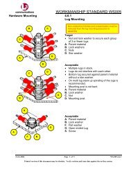
3.9.1 Hardware Mounting – Connector<br />
Screw Retaining Clips<br />
Acceptable<br />
� The formed thread (raised portion) of<br />
the clip is oriented opposite to the<br />
mating surface of the connector.<br />
� Screw is completely engaged through<br />
the thread (formed portion).<br />
<strong>WS</strong>-<strong>003</strong> Page 26 of 83<br />
Printed version of this document may be obsolete. Verify revision and issue date against the on-line system.
Workmanship Standard Level I <strong>WS</strong>-<strong>003</strong> Cable Harness Assembly<br />
Figure 3-33.<br />
Figure 3-34.<br />
Connectorization<br />
3.9.1 Hardware Mounting – Connector<br />
Screw Retaining Clips (cont.)<br />
Defect<br />
� The formed thread (raised portion) of<br />
the clip is oriented on the mating<br />
surface of the connector (Fig. 3-33 &<br />
Fig. 3-34).<br />
� Screw is not completely engaged<br />
through the thread (formed portion)<br />
(Fig.3-35).<br />
<strong>WS</strong>-<strong>003</strong> Page 27 of 83<br />
Printed version of this document may be obsolete. Verify revision and issue date against the on-line system.
Workmanship Standard Level I <strong>WS</strong>-<strong>003</strong> Cable Harness Assembly<br />
Figure 3-35.<br />
Connectorization<br />
3.9.1 Hardware Mounting – Connector<br />
Screw Retaining Clips (cont.)<br />
Defect (cont.)<br />
<strong>WS</strong>-<strong>003</strong> Page 28 of 83<br />
Printed version of this document may be obsolete. Verify revision and issue date against the on-line system.
Workmanship Standard Level I <strong>WS</strong>-<strong>003</strong> Cable Harness Assembly<br />
Connectorization<br />
3.9.2 Strain Relief – Clamp Fit<br />
Note:<br />
Insulating tape or sleeving may be used to prevent wire movement within the strain relief. Protective<br />
sleeving size can be changed to fit (see IS-001).<br />
Figure 3-36.<br />
Figure 3-37.<br />
Acceptable<br />
� Approved material used to “build-up”<br />
bundle diameter to provide contact<br />
support between the cable and strain<br />
relief clamp (insulating tape or sleeving<br />
may be used).<br />
� Split lock washer when used is fully<br />
compressed.<br />
Defect<br />
� Pinched sleeving or wire.<br />
� Split lock washer if used is not fully<br />
compressed.<br />
� Splice or ferrule located under the strain<br />
relief clamp (not shown).<br />
<strong>WS</strong>-<strong>003</strong> Page 29 of 83<br />
Printed version of this document may be obsolete. Verify revision and issue date against the on-line system.
Workmanship Standard Level I <strong>WS</strong>-<strong>003</strong> Cable Harness Assembly<br />
Connectorization<br />
3.9.3 Connector Damage – Cadmium<br />
Plated Surfaces<br />
This section addresses visual acceptance criteria of cadmium plated surfaces e.g.,<br />
connectors, adaptors, dust caps, etc. Only dust caps are shown due to the ease of displaying<br />
visual surface appearance. This criterion takes exception to IPC/WHMA-A-620A, 9.4.1, Defect<br />
– Class 2, 3, that does not allow exposure of base metal.<br />
For additional connector plating information see IS-001 Use of Non-Specified<br />
hardware/Material, clause 1.13 Connector Plating.<br />
Note: Surface finish inspection shall be performed without magnification.<br />
Note: Connectors that incorporate a jam nut retaining ring (Figure 3-38, A) as part of the cap<br />
restraining mechanism (chain/lanyard), the positioning of the jam nut retaining ring is not<br />
defined, unless dimensioned on the engineering drawing; however the retaining ring tab may<br />
not obscure any panel marking.<br />
Figure 3-38.<br />
Target<br />
� Free of scratches, mars, burrs, gouges,<br />
groves, scores or other damage.<br />
� Gasket material (located inside the cap)<br />
is in place (not shown).<br />
<strong>WS</strong>-<strong>003</strong> Page 30 of 83<br />
Printed version of this document may be obsolete. Verify revision and issue date against the on-line system.
Workmanship Standard Level I <strong>WS</strong>-<strong>003</strong> Cable Harness Assembly<br />
Connectorization<br />
3.9.3 Connector Damage – Cadmium Plated Surfaces (cont.)<br />
Figure 3-39.<br />
Acceptable<br />
� scratched, marred or burnished Figure 3-39.<br />
<strong>WS</strong>-<strong>003</strong> Page 31 of 83<br />
Printed version of this document may be obsolete. Verify revision and issue date against the on-line system.
Workmanship Standard Level I <strong>WS</strong>-<strong>003</strong> Cable Harness Assembly<br />
Figure 3-40.<br />
Defect<br />
� Scored, notched or gouged Figure 3-40.Burrs (not shown)<br />
� Jam nut retaining ring (when used) (see Figure 3-38, A) obscures panel marking (not shown).<br />
� Missing gasket, lanyard or other integral part (not shown).<br />
<strong>WS</strong>-<strong>003</strong> Page 32 of 83<br />
Printed version of this document may be obsolete. Verify revision and issue date against the on-line system.
Workmanship Standard Level I <strong>WS</strong>-<strong>003</strong> Cable Harness Assembly<br />
Connectorization<br />
3.9.4 Installation of Sealing Plugs into<br />
Shorting Blocks<br />
This section addresses sealing plugs that are installed into Terminal Junction/Shorting blocks. Figure<br />
3.41 illustrates a typical sealing plug (A). It should be noted that sealing plugs that feature a head are<br />
installed into the Terminal Junction/Shorting Block with the shaft first and the head against the insert<br />
grommet and the head completely visible.<br />
Acceptable<br />
Figure 3-41.<br />
(Shorting Blocks Only)<br />
� Sealing plug (A) is installed with the<br />
shaft first.<br />
� Sealing plug shaft is captured by the<br />
insert grommet (head is visible).<br />
Figure 3-42.<br />
Note: Where a sealing plug is installed, a<br />
contact will not be installed.<br />
Defect<br />
(Shorting Blocks Only)<br />
� Sealing Plug (A) installed head end first<br />
(head not visible).<br />
� Sealing plug(s) missing where required.<br />
<strong>WS</strong>-<strong>003</strong> Page 33 of 83<br />
Printed version of this document may be obsolete. Verify revision and issue date against the on-line system.
Workmanship Standard Level I <strong>WS</strong>-<strong>003</strong> Cable Harness Assembly<br />
Figure 3-43.<br />
Figure 3-44.<br />
Connectorization<br />
3.9.5 Raychem MTC 50 Connector<br />
Termination<br />
Target<br />
� The stripped conductor overlaps the<br />
connector terminal more than two<br />
stripped wire diameters.<br />
� The solder pre-form is completely<br />
melted and there is no remnant of the<br />
solder pre-form shape.<br />
� There is an acceptable solder fillet<br />
between the wire and the terminal.<br />
� The heat shrinkable sleeving (A) is fully<br />
shrunk onto the wire and the terminal.<br />
� The heat shrinkable sleeving is not<br />
burnt or charred, and does not have any<br />
splits or tears.<br />
� The minimum electrical clearance<br />
between electrically conductive<br />
surfaces. (B) is greater than .015 inch<br />
Note: Heat shrinkable sleeving has been<br />
partially removed for clarity.<br />
<strong>WS</strong>-<strong>003</strong> Page 34 of 83<br />
Printed version of this document may be obsolete. Verify revision and issue date against the on-line system.
Workmanship Standard Level I <strong>WS</strong>-<strong>003</strong> Cable Harness Assembly<br />
Figure 3-45.<br />
Figure 3-46.<br />
Figure 3-47.<br />
Connectorization<br />
3.9.5 Raychem MTC 50 Connector<br />
Termination (cont.)<br />
Acceptable<br />
� The wire overlaps the terminal a<br />
minimum of two stripped wire diameters.<br />
� Side overhang of the wire does not<br />
exceed 25% of the stripped wire<br />
diameter.<br />
� The minimum electrical clearance<br />
between electrically conductive surfaces<br />
(B) is a minimum of .015 inch.<br />
� There is a visible fillet between the wire<br />
and the terminal.<br />
Defect<br />
� Side overhang of the wire exceeds 25%<br />
of the stripped diameter.<br />
� The minimum electrical clearance<br />
between electrically conductive surfaces<br />
is less than .015 inch.<br />
� Wire overlap is less than two stripped<br />
wire diameters.<br />
� Heat shrinkable sleeving not completely<br />
shrunk.<br />
� The heat shrinkable sleeving is charred,<br />
split or torn.<br />
� The solder pre-form not completely<br />
flowed.<br />
� Wire insulation overlaps the solder<br />
termination area.<br />
<strong>WS</strong>-<strong>003</strong> Page 35 of 83<br />
Printed version of this document may be obsolete. Verify revision and issue date against the on-line system.
Workmanship Standard Level I <strong>WS</strong>-<strong>003</strong> Cable Harness Assembly<br />
Figure 3-48.<br />
Figure 3-49.<br />
Connectorization<br />
3.9.6 Raychem MTC 100 Connector<br />
Termination<br />
Solder ferrule (heat shrinkable device) consist<br />
of an outer shrinkable sleeve (1), two meltable<br />
sealing rings (2) and a solder ring (3) see<br />
Figure 3-48.<br />
Target<br />
� The stripped conductor extends the full<br />
length of the cupped area (4) of the<br />
solder terminal.<br />
� The stripped conductor overlaps the<br />
solder terminal (4) more than two<br />
stripped wire diameters.<br />
� The stripped conductor is parallel to the<br />
solder terminal.<br />
� The wire insulation (5) has not entered<br />
the solder terminal area.<br />
� The meltable sealing ring (3) is<br />
overlapping the wire insulation.<br />
� The end of solder ferrule sleeve (2) is<br />
within .040 inch of the connector body<br />
(1).<br />
� Solder preform (ring) is completely<br />
melted and a properly wetted and a fillet<br />
is visible between the lead and the<br />
terminal.<br />
� The meltable sealing rings (3) have<br />
melted and flowed.<br />
� The shrinkable sleeve or the wire<br />
insulation show no sign of discoloration.<br />
<strong>WS</strong>-<strong>003</strong> Page 36 of 83<br />
Printed version of this document may be obsolete. Verify revision and issue date against the on-line system.
Workmanship Standard Level I <strong>WS</strong>-<strong>003</strong> Cable Harness Assembly<br />
Figure 3-50.<br />
Figure 3-51.<br />
Connectorization<br />
3.9.6 Raychem MTC 100 Connector<br />
Termination (cont.)<br />
Acceptable<br />
� The wire overlaps the terminal a<br />
minimum of two stripped wire diameters.<br />
� Side overhang of the wire does not<br />
exceed 25% of the stripped wire<br />
diameter.<br />
� Conductors have not ruptured or<br />
damaged the ferrule (shrinkable) sleeve.<br />
� Shrinkable sleeve is discolored but is<br />
not burnt or charred.<br />
� Solder fillet is visible between the lead<br />
and the terminal.<br />
� Solder pre-form has flowed properly<br />
leaving no evidence of solder ring.<br />
� No pits or cracks are visible in the<br />
connector body.<br />
<strong>WS</strong>-<strong>003</strong> Page 37 of 83<br />
Printed version of this document may be obsolete. Verify revision and issue date against the on-line system.
Workmanship Standard Level I <strong>WS</strong>-<strong>003</strong> Cable Harness Assembly<br />
Figure 3-52.<br />
Figure 3-53.<br />
Connectorization<br />
3.9.6 Raychem MTC 100 Connector<br />
Termination (cont.)<br />
Defect<br />
� Side overhang of the wire exceeds 25%<br />
� Conductor strands are protruding<br />
through the solder ferrule sleeve<br />
� Wire overlap is less than 2 wire<br />
diameters.<br />
� Incomplete reflow of the solder preform.<br />
� The shrinkable sleeving is charred, split<br />
or torn.<br />
� Wire insulation overlaps the solder<br />
termination area.<br />
� Solder fillet not visible between the lead<br />
and the terminal.<br />
� Pits or cracks are visible in the<br />
connector body (applies to both MTC 50<br />
and MTC 100 connectors).<br />
<strong>WS</strong>-<strong>003</strong> Page 38 of 83<br />
Printed version of this document may be obsolete. Verify revision and issue date against the on-line system.
Workmanship Standard Level I <strong>WS</strong>-<strong>003</strong> Cable Harness Assembly<br />
Figure 3-54. (Sealing Boot)<br />
Figure 3-55.<br />
Connectorization<br />
3.9.6.1 Raychem MTC 100 Connector<br />
Termination – Sealing Boot<br />
Note: Criteria apply to both MTC50 and MTC<br />
100 connectors.<br />
MTC 100 and MTC 50 sealing boots consist of<br />
heat shrinkable sleeve and meltable adhesive<br />
inside the boot (see Figure 3-54).<br />
Acceptable<br />
� Sealing boot is shrunk (boot is tight).<br />
� Meltable adhesive has properly flowed.<br />
� Insulating boot is discolored but is not<br />
split, torn burnt or charred.<br />
� Boot is properly positioned (overlaps<br />
onto the connector and the wire<br />
insulation).<br />
Defect (no illustrations)<br />
� Boot is loose<br />
� Meltable adhesive has not completely<br />
flowed.<br />
� Boot is split, torn or charred.<br />
� Pits or cracks are visible in the<br />
connector body<br />
<strong>WS</strong>-<strong>003</strong> Page 39 of 83<br />
Printed version of this document may be obsolete. Verify revision and issue date against the on-line system.
Workmanship Standard Level I <strong>WS</strong>-<strong>003</strong> Cable Harness Assembly<br />
Figure 3-56.<br />
Figure 3-57.<br />
Connectorization<br />
3.9.6.2 Raychem MTC 100 Connector<br />
Termination – Flat Cable<br />
Note: Criteria apply to both MTC50 and MTC<br />
100 connectors.<br />
Acceptable<br />
� Flat cable is oriented correctly (color<br />
strip or numbers or letters identify pin<br />
one).<br />
� Cable is not misaligned (skewed).<br />
� Boot is not damaged.<br />
� Acceptable solder fillets are evident.<br />
� Conductor side overhang is less than<br />
25% of the conductor width.<br />
� Shrinkable sleeving or boot discolored<br />
but not burnt or charred.<br />
Defect<br />
� Flat cable misaligned, side overhang is<br />
greater than 25% of the conductor width<br />
or violates electrical clearance.<br />
� Flat cable is oriented incorrectly (color<br />
strip or numbers or letters) not matching<br />
connector pin one.<br />
� Overheated or disturbed solder.<br />
� Shrinkable sleeving or boot is split, torn<br />
or charred.<br />
� Solder rings not completely flowed.<br />
� Meltable adhesive not flowed.<br />
� Boot is loose or not completely shrunk.<br />
� Connector body damage pits or cracks.<br />
<strong>WS</strong>-<strong>003</strong> Page 40 of 83<br />
Printed version of this document may be obsolete. Verify revision and issue date against the on-line system.
Workmanship Standard Level I <strong>WS</strong>-<strong>003</strong> Cable Harness Assembly<br />
Figure 3-58.<br />
Figure 3-59.<br />
3.10 Molding/Potting<br />
Molding/Potting<br />
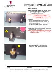
3.10.1 EMI/RFI Shielding – Foil (prior to<br />
molding)<br />
Target<br />
� Solder fillet is visible for the full length of<br />
any location where foil is overlapped.<br />
� Foil is soldered for 360º of the folded<br />
back portion of the cable braid and foil<br />
interface (no voids), Fig. 3-58.<br />
� The cable braid fold back is not bridged<br />
to the cable braid junction, Fig. 3-58.<br />
� No openings or holes in the foil.<br />
� No flux, flux residue, sharp points or<br />
icicles.<br />
<strong>WS</strong>-<strong>003</strong> Page 41 of 83<br />
Printed version of this document may be obsolete. Verify revision and issue date against the on-line system.
Workmanship Standard Level I <strong>WS</strong>-<strong>003</strong> Cable Harness Assembly<br />
Figure 3-60.<br />
Figure 3-61.<br />
Molding/Potting<br />
3.10.1 EMI/RFI Shielding – Foil (prior to<br />
molding) (cont.)<br />
Target (cont.)<br />
Acceptable<br />
� Solder (thin film) visible on the<br />
connector, Fig. 3-63.<br />
� Solder bridged between foil and braid<br />
fold back, Fig. 3-61.<br />
� Braid soldered directly to foil, no fold<br />
back (not preferred), Fig. 3-62.<br />
� Foil opening/damage covered with a foil<br />
patch and soldered in place, Fig. 3-64.<br />
� 75% minimum solder coverage along<br />
any length of a lap soldered joint.<br />
� 90% minimum solder coverage of the<br />
circumference of the braid to the foil<br />
interface. (Fig. 3-60)<br />
<strong>WS</strong>-<strong>003</strong> Page 42 of 83<br />
Printed version of this document may be obsolete. Verify revision and issue date against the on-line system.
Workmanship Standard Level I <strong>WS</strong>-<strong>003</strong> Cable Harness Assembly<br />
Figure 3-62.<br />
Figure 3-63.<br />
Molding/Potting<br />
3.10.1 EMI/RFI Shielding – Foil (prior to<br />
molding) (cont.)<br />
Acceptable (cont.)<br />
<strong>WS</strong>-<strong>003</strong> Page 43 of 83<br />
Printed version of this document may be obsolete. Verify revision and issue date against the on-line system.
Workmanship Standard Level I <strong>WS</strong>-<strong>003</strong> Cable Harness Assembly<br />
Figure 3-64.<br />
Figure 3-65.<br />
Molding/Potting<br />
3.10.1 EMI/RFI Shielding – Foil (prior to<br />
molding) (cont.)<br />
Acceptable (cont.)<br />
Defect<br />
� Solder buildup that affects subsequent<br />
process steps.<br />
� Any foil opening or hole.<br />
� Less than 75% solder coverage along<br />
any length of a lap soldered joint.<br />
� Less than 90% solder coverage of the<br />
fold back (Fig. 3-60) or the direct<br />
soldered braid (Fig. 3-62) and foil<br />
interface.<br />
� Dewetting or disturbed solder.<br />
� Solder cracks or fractures.<br />
� Dirt, flux, flux residue, points, or icicles.<br />
<strong>WS</strong>-<strong>003</strong> Page 44 of 83<br />
Printed version of this document may be obsolete. Verify revision and issue date against the on-line system.
Workmanship Standard Level I <strong>WS</strong>-<strong>003</strong> Cable Harness Assembly<br />
Figure 3-66.<br />
Molding/Potting<br />
3.10.1 EMI/RFI Shielding – Foil (prior to<br />
molding) (cont.)<br />
Defect (cont.)<br />
<strong>WS</strong>-<strong>003</strong> Page 45 of 83<br />
Printed version of this document may be obsolete. Verify revision and issue date against the on-line system.
Workmanship Standard Level I <strong>WS</strong>-<strong>003</strong> Cable Harness Assembly<br />
Molding/Potting<br />
3.10.2 Hardware installation –<br />
Jackscrews<br />
The criteria in this section addresses the installation of connector mounting hardware (i.e., jackscrews<br />
or jackposts) in injection molded or cold pour potted connectors.<br />
Note: A trial mating of connector to connector or connector to assembly may be required for final<br />
acceptance.<br />
Target<br />
Figure 3-67.<br />
� Mold design provides clearance for<br />
hardware installation.<br />
� Mates properly with mating connector<br />
hardware.<br />
Figure 3-68.<br />
<strong>WS</strong>-<strong>003</strong> Page 46 of 83<br />
Printed version of this document may be obsolete. Verify revision and issue date against the on-line system.
Workmanship Standard Level I <strong>WS</strong>-<strong>003</strong> Cable Harness Assembly<br />
Figure 3-69.<br />
Figure 3-70.<br />
Molding/Potting<br />
3.10.2 Hardware installation –<br />
Jackscrews (cont.)<br />
Acceptable<br />
� Molding material does not obstruct or<br />
interfere with the mounting hardware.<br />
� Mold obstruction adjacent the mounting<br />
hardware is trimmed flush to the surface<br />
to provide hardware clearance.<br />
<strong>WS</strong>-<strong>003</strong> Page 47 of 83<br />
Printed version of this document may be obsolete. Verify revision and issue date against the on-line system.
Workmanship Standard Level I <strong>WS</strong>-<strong>003</strong> Cable Harness Assembly<br />
Figure 3-71.<br />
Figure 3-72.<br />
Molding/Potting<br />
3.10.2 Hardware installation –<br />
Jackscrews (cont.)<br />
Defect<br />
� Connector hardware is misaligned due<br />
to molding obstruction.<br />
� Will not mate with mating connector<br />
hardware.<br />
� Un-authorized trimming or modification<br />
that reduces the molded surface below<br />
flush (see Figure 3-73).<br />
� Trimming or damage to the molding<br />
material that exposes the foil or<br />
connector housing.<br />
� Un-authorized repair. (Not shown)<br />
<strong>WS</strong>-<strong>003</strong> Page 48 of 83<br />
Printed version of this document may be obsolete. Verify revision and issue date against the on-line system.
Workmanship Standard Level I <strong>WS</strong>-<strong>003</strong> Cable Harness Assembly<br />
Figure 3-73.<br />
Molding/Potting<br />
3.10.2 Hardware installation –<br />
Jackscrews (cont.)<br />
Defect (cont.)<br />
� Trimming or modification that reduces<br />
the molded surface below flush.<br />
<strong>WS</strong>-<strong>003</strong> Page 49 of 83<br />
Printed version of this document may be obsolete. Verify revision and issue date against the on-line system.
Workmanship Standard Level I <strong>WS</strong>-<strong>003</strong> Cable Harness Assembly<br />
Molding/Potting<br />
3.10.3 Potting – Cold Pour, Room<br />
Temperature Vulcanization (RTV)<br />
When cold pour, RTV, is used to assemble/manufacture cable harness assemblies the materials and<br />
processes shall be selected such that their use, in combination, are compatible and produce products<br />
that meet the following requirements.<br />
Figure 3-74.<br />
Target (Not Illustrated)<br />
� Potting material is in contact with the<br />
connector and has no gaps, or cracks<br />
and the connector is secure in the<br />
potting material.<br />
� Potting material does not affect form, fit<br />
or function of the connector.<br />
� No potting material on the mating<br />
surfaces of the connector/contacts.<br />
� No evidence of flash, voids, bubbles,<br />
foreign material or entrapped air.<br />
Acceptable<br />
� Potting material secures the connector<br />
� Voids or separations that do not expose<br />
wire[s] or conductor[s].<br />
� Potting material or flash that does not<br />
interfere with form fit or function<br />
<strong>WS</strong>-<strong>003</strong> Page 50 of 83<br />
Printed version of this document may be obsolete. Verify revision and issue date against the on-line system.
Workmanship Standard Level I <strong>WS</strong>-<strong>003</strong> Cable Harness Assembly<br />
Figure 3-75.<br />
Molding/Potting<br />
3.10.3 Potting – Cold Pour, Room<br />
Temperature Vulcanization (RTV) (cont.)<br />
Defect<br />
� Exposed wire[s] or conductor[s].<br />
� Cracks or splits in the potting material.<br />
� Potting material present on mating<br />
surfaces of connector or contacts<br />
� Potting material that affects form, fit or<br />
function of the connector or contacts.<br />
� Connector is not secured in the potting<br />
material.<br />
� Voids or separations that expose wire[s]<br />
or conductor[s].<br />
<strong>WS</strong>-<strong>003</strong> Page 51 of 83<br />
Printed version of this document may be obsolete. Verify revision and issue date against the on-line system.
Workmanship Standard Level I <strong>WS</strong>-<strong>003</strong> Cable Harness Assembly<br />
Figure 3-76.<br />
Figure 3-77.<br />
Molding/Potting<br />
3.10.3.1 Potting – Cold Pour, Room<br />
Temperature Vulcanization (RTV) – Fit to<br />
Wire or Cable<br />
Target<br />
� Potting material is in contact with the<br />
entire circumference of wire[s], sleeve<br />
or cable jacket interface.<br />
� Cable axis is on line with the connector<br />
axis per design.<br />
� Cable is centered within the potting and<br />
cable interface.<br />
<strong>WS</strong>-<strong>003</strong> Page 52 of 83<br />
Printed version of this document may be obsolete. Verify revision and issue date against the on-line system.
Workmanship Standard Level I <strong>WS</strong>-<strong>003</strong> Cable Harness Assembly<br />
Figure 3-78.<br />
Figure 3-79.<br />
Molding/Potting<br />
3.10.3.1 Potting – Cold Pour, Room<br />
Temperature Vulcanization (RTV) – Fit to<br />
Wire or Cable (cont.)<br />
Acceptable<br />
� Potting material is in contact with<br />
wire[s], sleeve or cable jacket but may<br />
have separation or gaps providing<br />
internal components (e.g., wire[s]<br />
shielding, etc.) are not visible.<br />
� Cable axis has a measured angle less<br />
than or equal to 15º from the connector<br />
axis design.<br />
� Cable may be off centered in the potting<br />
material providing dimension (DIM) B<br />
does not exceed 2X (times) dimension<br />
(DIM) A.<br />
Defect<br />
� Internal components visible between<br />
wire[s], sleeve or cable jacket and<br />
potting material.<br />
� Cable axis has a measured angle<br />
greater than 15º from the connector axis<br />
design.<br />
� Cable is off centered in the potting<br />
material where dimension (DIM) B<br />
exceeds 2X (times) dimension (DIM) A.<br />
<strong>WS</strong>-<strong>003</strong> Page 53 of 83<br />
Printed version of this document may be obsolete. Verify revision and issue date against the on-line system.
Workmanship Standard Level I <strong>WS</strong>-<strong>003</strong> Cable Harness Assembly<br />
Figure 3-80.<br />
Molding/Potting<br />
3.10.3.1 Potting – Cold Pour, Room<br />
Temperature Vulcanization (RTV) – Fit to<br />
Wire or Cable (cont.)<br />
Defect (cont.)<br />
<strong>WS</strong>-<strong>003</strong> Page 54 of 83<br />
Printed version of this document may be obsolete. Verify revision and issue date against the on-line system.
Workmanship Standard Level I <strong>WS</strong>-<strong>003</strong> Cable Harness Assembly<br />
Molding/Potting<br />
3.10.3.2 Potting – Cold Pour, Room<br />
Temperature Vulcanization (RTV) – Curing<br />
(There are no Illustrations for this section).<br />
Target<br />
� Potting material is cured and is not<br />
tacky.<br />
� Potting material meets hardness range<br />
(when specified).<br />
Acceptable<br />
� Potting material has hardened and is<br />
tack free to the touch<br />
Defect<br />
� Potting material is tacky.<br />
� Does not meet hardness range (when<br />
specified).<br />
<strong>WS</strong>-<strong>003</strong> Page 55 of 83<br />
Printed version of this document may be obsolete. Verify revision and issue date against the on-line system.
Workmanship Standard Level I <strong>WS</strong>-<strong>003</strong> Cable Harness Assembly<br />
Molding/Potting<br />
3.10.3.3 Potting – Cold Pour, Room<br />
Temperature Vulcanization (RTV) –<br />
Rework/Touchup<br />
Note: Rework/touchup of the potted assembly<br />
must be completed using the same material.<br />
Acceptable<br />
� Rework/touchup that does not affect<br />
form, fit or function.<br />
Defect<br />
� Rework/touchup that affects form, fit or<br />
function.<br />
� Rework/touchup material is different<br />
than the original potting material used.<br />
<strong>WS</strong>-<strong>003</strong> Page 56 of 83<br />
Printed version of this document may be obsolete. Verify revision and issue date against the on-line system.
Workmanship Standard Level I <strong>WS</strong>-<strong>003</strong> Cable Harness Assembly<br />
3.11 Cable Assemblies and Wires<br />
(See IPC/WHMA-A-620 for criteria)<br />
Page intentionally left blank.<br />
<strong>WS</strong>-<strong>003</strong> Page 57 of 83<br />
Printed version of this document may be obsolete. Verify revision and issue date against the on-line system.
Workmanship Standard Level I <strong>WS</strong>-<strong>003</strong> Cable Harness Assembly<br />
3.12 Marking and Labeling<br />
Marking and Labeling<br />
3.12.1 Part or Identifying Number<br />
(PIN)/Marker Sleeving.<br />
See <strong>WS</strong>-012, for definition of broken lines,<br />
hidden lines; near side, far side and 7 digit part<br />
numbers and suffix, 8 digit part numbers and<br />
suffix also see IS-008.<br />
Note: Acceptance criteria for marking and<br />
labeling of cables and wire harnesses are<br />
located in IPC/WHMA-A-620.<br />
Caution:<br />
When installing marking labels on Fiber-Optic<br />
cables, markers shall be spaced a minimum of<br />
1.5 inches apart.<br />
<strong>WS</strong>-<strong>003</strong> Page 58 of 83<br />
Printed version of this document may be obsolete. Verify revision and issue date against the on-line system.
Workmanship Standard Level I <strong>WS</strong>-<strong>003</strong> Cable Harness Assembly<br />
Marking and Labeling<br />
3.12.2 UID Labels<br />
The UID Matrix label typically includes the cage code, part number, and serial number. The Part<br />
Identifying Number (PIN) may also include other information such as job number, revision, and<br />
identifiers such as (17V) for cage code,(IP) for original part number, and (S) for serial number,<br />
characteristics of the UID.<br />
� The UID Matrix label must meet the required quality level.<br />
� The UID Matrix label must meet machine readability requirements.<br />
� The UID Matrix label must be free of any obstructions.<br />
Figure 3-81.<br />
Figure 3-82.<br />
Acceptable<br />
� UID matrix is completely visible.<br />
� UID matrix is flat.<br />
Defect<br />
� Label/marker not located per<br />
documentation.<br />
� UID matrix symbol not completely<br />
visible, is partially obstructed, marked<br />
over or damaged. .<br />
� UID matrix symbol does not meet the<br />
quality level required.<br />
� UID matrix symbol not machine<br />
readable.<br />
� Other markings don’t meet marking<br />
requirements of IPC/WHMA-A-620.<br />
� UID matrix is not flat.<br />
� Alpha/numeric printing not legible.<br />
<strong>WS</strong>-<strong>003</strong> Page 59 of 83<br />
Printed version of this document may be obsolete. Verify revision and issue date against the on-line system.
Workmanship Standard Level I <strong>WS</strong>-<strong>003</strong> Cable Harness Assembly<br />
Marking and Labeling<br />
3.12.3 Flag Markers - Adhesive<br />
This section provides illustrations of adhesive flag markers; see IPC/WHMA-A-620, Section 12.<br />
Figure 3-83.<br />
Figure 3-84.<br />
Figure 3-85.<br />
Target<br />
� See IPC/WHMA-A-620.<br />
Acceptable<br />
� Edges of flag marker misaligned less<br />
than 25% of the width of the marker.<br />
Defect<br />
� See IPC/WHMA-A-620.<br />
� Marker not secure on cable/harness.<br />
<strong>WS</strong>-<strong>003</strong> Page 60 of 83<br />
Printed version of this document may be obsolete. Verify revision and issue date against the on-line system.
Workmanship Standard Level I <strong>WS</strong>-<strong>003</strong> Cable Harness Assembly<br />
Figure 3-86.<br />
Figure 3-87.<br />
3.13 Coaxial and Twinaxial Cable Assemblies<br />
Coaxial & Twinaxial Cable Assemblies<br />
3.13.1 Center Conductor Termination –<br />
Coax Pin Insulation Gap<br />
Target<br />
� Insulation end (dielectric) is positioned<br />
within solder cup and support barrel<br />
area (A).<br />
Note: Center conductor must be inserted for<br />
the full depth of the cup.<br />
Acceptable<br />
Insulation end contacts the solder cup but does<br />
not prevent the formation of an acceptable<br />
solder connection.<br />
<strong>WS</strong>-<strong>003</strong> Page 61 of 83<br />
Printed version of this document may be obsolete. Verify revision and issue date against the on-line system.
Workmanship Standard Level I <strong>WS</strong>-<strong>003</strong> Cable Harness Assembly<br />
Figure 3-88.<br />
Coaxial & Twinaxial Cable Assemblies<br />
3.13.1 Center Conductor Termination –<br />
Coax Pin Insulation Gap (cont.)<br />
Defect<br />
� Insulation (dielectric) end is not<br />
positioned within solder cup and support<br />
barrel area (A).<br />
� Insulation end prevents the formation of<br />
an acceptable solder connection (not<br />
shown).<br />
<strong>WS</strong>-<strong>003</strong> Page 62 of 83<br />
Printed version of this document may be obsolete. Verify revision and issue date against the on-line system.
Workmanship Standard Level I <strong>WS</strong>-<strong>003</strong> Cable Harness Assembly<br />
3.14 Securing<br />
This Section illustrates Low Profile tie wraps. Low pofile tie wraps should be used instead of the<br />
standard tie wraps or lacing /string tie as called out on the part list/drawing. The tie wrap size shall be<br />
in accordance with the chart located in IS-001. Acceptance criteria is the same as the standard tie wrap<br />
(see IPC-A-620, Section 14).<br />
Figure 3-89.<br />
Figure 3-90.<br />
Securing<br />
3.14.1 Tie Wrap Application – Low<br />
Profile<br />
Acceptable<br />
� Wire bundle is secured.<br />
� Insulation is not compressed or<br />
damaged by the restraining device.<br />
� The end of the tie wrap is cut-off not<br />
greater than 1 tie wrap thickness and is<br />
reasonably square to the face of the<br />
wrap.<br />
� No sharp points or edges.<br />
Note:<br />
For fiber optic cable routing and<br />
Securing, See <strong>WS</strong>-005.<br />
<strong>WS</strong>-<strong>003</strong> Page 63 of 83<br />
Printed version of this document may be obsolete. Verify revision and issue date against the on-line system.
Workmanship Standard Level I <strong>WS</strong>-<strong>003</strong> Cable Harness Assembly<br />
Figure 3-91.<br />
Figure 3-92.<br />
Securing<br />
3.14.1 Tie Wrap Application – Low<br />
Profile (cont.)<br />
Defect<br />
� Cut end protrusion extends more than 1<br />
tie wrap thickness.<br />
� Bundle or insulation is compressed,<br />
distorted or damaged by the tie wrap.<br />
� Not cut square (A) is sharp or<br />
hazardous.<br />
<strong>WS</strong>-<strong>003</strong> Page 64 of 83<br />
Printed version of this document may be obsolete. Verify revision and issue date against the on-line system.
Workmanship Standard Level I <strong>WS</strong>-<strong>003</strong> Cable Harness Assembly<br />
Figure 3-93.<br />
Figure 3-94.<br />
Securing<br />
3.14.2 Excess Wire Length – Loop in<br />
Bundle<br />
Note: This section only applies to wires<br />
terminated from point to point. Does not apply<br />
to pick-off or drain wires.<br />
Defect<br />
� Excess wire length is looped or folded<br />
back.<br />
<strong>WS</strong>-<strong>003</strong> Page 65 of 83<br />
Printed version of this document may be obsolete. Verify revision and issue date against the on-line system.
Workmanship Standard Level I <strong>WS</strong>-<strong>003</strong> Cable Harness Assembly<br />
Figure 3-95.<br />
Figure 3-96.<br />
Securing<br />
3.14.2 Excess Wire Length – Loop in<br />
Bundle (cont.)<br />
Defect (cont.)<br />
<strong>WS</strong>-<strong>003</strong> Page 66 of 83<br />
Printed version of this document may be obsolete. Verify revision and issue date against the on-line system.
Workmanship Standard Level I <strong>WS</strong>-<strong>003</strong> Cable Harness Assembly<br />
3.15 Harness/Cable Electrical Shielding<br />
Harness/Cable Electrical Shielding<br />
3.15.1 Shield Termination – Braided pick<br />
off<br />
This criterion applies to soldered/heat shrinkable solder devices that incorporate a braided pick off lead<br />
instead of a stranded wire pick off. Braided pick off is not sleeved, unless specified by the engineering<br />
drawing.<br />
Figure 3-97.<br />
Figure 3-98.<br />
Acceptable (unsleeved)<br />
� Solder ring is completely melted wetting<br />
the braid and the cable shield and<br />
meets the requirements of IPC/WHMA-<br />
A-620, Section 15.<br />
� Crimp termination meets the<br />
requirements of IPC/WHMA-A-620,<br />
Section 5.<br />
� Braid is undamaged.<br />
Acceptable (sleeved)<br />
When the braided pick off is required to<br />
be sleeved the following are met:<br />
� Solder ring is completely melted wetting<br />
the braid and the cable shield and<br />
meets the requirements of IPC/WHMA-<br />
A-620, Section 15.<br />
� Sleeving is tight on the braid.<br />
� No cracks, tears or burns.<br />
� The braid sleeving is flush to the heat<br />
shrink device.<br />
� The braid sleeving extends into the<br />
insulation crimp area of the crimped<br />
termination.<br />
<strong>WS</strong>-<strong>003</strong> Page 67 of 83<br />
Printed version of this document may be obsolete. Verify revision and issue date against the on-line system.
Workmanship Standard Level I <strong>WS</strong>-<strong>003</strong> Cable Harness Assembly<br />
Harness/Cable Electrical Shielding<br />
3.15.1 Shield Termination – Braided pick<br />
off (cont.)<br />
Defect (Not Illustrated)<br />
� When required to be sleeved, braid is<br />
not sleeved.<br />
� When sleeved the insulation gap<br />
between the sleeving and the heat<br />
shrink device is greater than 2 sleeving<br />
diameters.<br />
� Violation of soldering requirements, see<br />
IPC/WHMA-A-620, Section 15.<br />
� Violation of crimping requirements, see<br />
IPC/WHMA-A-620, Section 5.<br />
� Braid is damaged.<br />
<strong>WS</strong>-<strong>003</strong> Page 68 of 83<br />
Printed version of this document may be obsolete. Verify revision and issue date against the on-line system.
Workmanship Standard Level I <strong>WS</strong>-<strong>003</strong> Cable Harness Assembly<br />
Harness/Cable Electrical Shielding<br />
3.15.2 Shield Termination – Soldered to<br />
Connector Housing<br />
This section is only applicable when specified by engineering documentation. This section addresses<br />
wires soldered to metal connector housings. Typically this type of termination requires the plating to be<br />
removed from a limited portion of the connector housing in order to create a solderable surface.<br />
Figure 3-99.<br />
Acceptable<br />
� Wire overlap to the metal surface is<br />
greater than 3, less than 5 wire<br />
diameters.<br />
� The wire is in contact with and parallel<br />
to the metal surface of the connector.<br />
� Solder is wetted and forms a fillet from<br />
the wire to the metal connector housing<br />
a minimum of 3 wire diameters.<br />
� Wire contour is visible in the solder.<br />
� Damage to the non-metal portion of the<br />
connector has not distorted the contact<br />
cavity.<br />
� Insulation gap is within 2 wire diameters<br />
of solder fillet.<br />
� Connector is clean and free of flux<br />
residue and foreign matter<br />
� The buffed metal area of the connector<br />
is covered with wetted solder or other<br />
approved coating.<br />
<strong>WS</strong>-<strong>003</strong> Page 69 of 83<br />
Printed version of this document may be obsolete. Verify revision and issue date against the on-line system.
Workmanship Standard Level I <strong>WS</strong>-<strong>003</strong> Cable Harness Assembly<br />
Figure 3-100.<br />
Harness/Cable Electrical Shielding<br />
3.15.2 Shield Termination – Soldered to<br />
Connector Housing (cont.)<br />
Defect<br />
� Wire or insulation damage beyond limits<br />
(see IPC/WHMA-A-620).<br />
� Soldered portion of the ground wire is<br />
not parallel to the connector surface.<br />
� Wire is not in contact with the metal<br />
surface.<br />
� Wire overlap is less than 3 or greater<br />
than 5 wire diameters.<br />
� Solder wetting at the connector and wire<br />
interface is less than 3 wire diameters in<br />
length.<br />
� Solder is dewetted or nowetted.<br />
� Contact cavity (dielectric) of the<br />
connector is distorted.<br />
� Insulation gap greater than 2 wire<br />
diameters from solder fillet.<br />
� Flux residue or foreign matter evident<br />
on solder connection, connector or<br />
connector contacts.<br />
� The buffed metal area of the connector<br />
is not covered with wetted solder or<br />
other approved coating.<br />
<strong>WS</strong>-<strong>003</strong> Page 70 of 83<br />
Printed version of this document may be obsolete. Verify revision and issue date against the on-line system.
Workmanship Standard Level I <strong>WS</strong>-<strong>003</strong> Cable Harness Assembly<br />
Figure 3-101.<br />
3.16 Cable Harness Protective Coverings<br />
Cable Harness Protective Coverings<br />
3.16.1 Braid - Prewoven (plastic)<br />
Acceptable<br />
� Braid strands are separated to allow<br />
wire passage.<br />
� Braid strands not cut or damaged.<br />
� Braid is not ballooned or bunched.<br />
Defect (See IPC/WHMA-A-620, Section 16,<br />
for Additional Illustrations)<br />
� Braid damage i.e., tears, cuts, broken,<br />
or melted.<br />
� Braid is ballooned or bunched.<br />
<strong>WS</strong>-<strong>003</strong> Page 71 of 83<br />
Printed version of this document may be obsolete. Verify revision and issue date against the on-line system.
Workmanship Standard Level I <strong>WS</strong>-<strong>003</strong> Cable Harness Assembly<br />
Cable Harness Protective Coverings<br />
3.16.2 Heat Shrink Tubing – Indoor<br />
Applications<br />
Note: Unless otherwise specified on the engineering drawing, all cable and wire harness assemblies<br />
are considered to be designed for an indoor environment.<br />
Sleeving or boots overlapped on clampless adaptors are required to be adhesive bonded in place and<br />
shall meet the bonding requirements of this section. Adhesive lined sleeving e.g., boots satisfy the<br />
bonding requirements when specified on the engineering parts list. When adhesive lined sleeving (e.g.,<br />
boots) is used, evidence of the adhesive may not be visible at the overlapped junction. Other sleeving<br />
overlapped junctions are not required to be adhesive bonded, unless specified per engineering<br />
documentation. However when adhesive bonding material is not listed on the engineering parts list, a<br />
harnessing adhesive (part number 7917693-00) may be applied to any interface between the<br />
connector backshell and/or the connector and the cable jacket as part of the standard process. A<br />
harnessing epoxy may also be applied to any sleeving overlap, junction, or splice as part of the<br />
standard process; see IS-001. When adhesive bonding is used it shall be bonded for a minimum of<br />
270º (75%) of the circumference of the sleeving.<br />
Figure 3-102.<br />
Figure 3-103.<br />
Cable Harness Protective Coverings<br />
3.16.2.1 Heat Shrink Tubing – Indoor<br />
Applications Breakouts & Sleeving<br />
Splices<br />
Acceptable<br />
� Sleeving is overlapped a minimum of 3<br />
cable diameters, or 0.5 inch whichever<br />
is greater.<br />
� Sleeving is shrunk and there is no<br />
lateral movement of the sleeving.<br />
Defect<br />
� Sleeving overlap is less than 0.5 inch or<br />
less than 3 cable diameters if 3 cable<br />
diameters exceed 0.5 inch.<br />
� Lateral movement of the sleeving<br />
(loose).<br />
<strong>WS</strong>-<strong>003</strong> Page 72 of 83<br />
Printed version of this document may be obsolete. Verify revision and issue date against the on-line system.
Workmanship Standard Level I <strong>WS</strong>-<strong>003</strong> Cable Harness Assembly<br />
Figure 3-104.<br />
Figure 3-105.<br />
Cable Harness Protective Coverings<br />
3.16.2.2 Heat Shrink Tubing – Indoor<br />
Applications – Cable Jacket/Sleeving<br />
Position<br />
Acceptable<br />
� Cable jacket/sleeving (B) extends to<br />
within one cable diameter of the<br />
clampless adapter (A).<br />
� When heat shrink sleeving is used for<br />
the outer protective covering it is shrunk<br />
and there is no lateral movement.<br />
� Environmental connector (C) the cable<br />
jacket/sleeving extends into the sealing<br />
grommet (D).<br />
� Cable jacket/sleeving extends slightly<br />
past the adapter clamps.<br />
Note: Figure 3-104 illustrates a connector with<br />
a clampless adapter this configuration requires<br />
a boot/sleeving, see 3.16.3.3.<br />
<strong>WS</strong>-<strong>003</strong> Page 73 of 83<br />
Printed version of this document may be obsolete. Verify revision and issue date against the on-line system.
Workmanship Standard Level I <strong>WS</strong>-<strong>003</strong> Cable Harness Assembly<br />
� Figure 3-106.<br />
� Figure 3-107.<br />
Cable Harness Protective Coverings<br />
3.16.2.2 Heat Shrink Tubing – Indoor<br />
Applications – Cable Jacket/Sleeving<br />
Position (cont.)<br />
Defect<br />
� Cable jacket/sleeving (B) does not<br />
extend to within one cable diameter of<br />
the clampless adapter (A).<br />
� Loose sleeving (if used).<br />
� On an environmental connector (C) the<br />
cable jacket/sleeving does not extend<br />
into the sealing grommet (D).<br />
� Connectors that have (strain relief<br />
clamps see IPC/WHMA- A-620, Section<br />
9 for acceptance criteria.<br />
<strong>WS</strong>-<strong>003</strong> Page 74 of 83<br />
Printed version of this document may be obsolete. Verify revision and issue date against the on-line system.
Workmanship Standard Level I <strong>WS</strong>-<strong>003</strong> Cable Harness Assembly<br />
Figure 3-108.<br />
Figure 3-109.<br />
Cable Harness Protective Coverings<br />
3.16.2.3 Heat Shrink Tubing – Indoor<br />
Applications – Boots/Sleeving<br />
Acceptable<br />
� Boot/sleeving (A) extends onto the<br />
clampless adapter a minimum of 50% of<br />
adapter length.<br />
� Boot/sleeving is shrunk and snug (no<br />
lateral movement).<br />
� The boot/sleeving is bonded (B) to the<br />
clampless adapter for a minimum of<br />
270º (75%) of its circumference.<br />
� The boot/sleeving overlaps the cable<br />
jacket a minimum of 3 cable diameters,<br />
or 0.5 inch whichever is greater.<br />
Note: The boot/sleeving is not required to be<br />
bonded to the cable Jacket/sleeving.<br />
Defect<br />
� Boot/Sleeving is overlapped less than<br />
50% of the clampless adapter length<br />
(A).<br />
� Boot/ sleeving is not shrunk or has<br />
lateral movement.<br />
� The boot/sleeving is bonded less than<br />
270º (75%) of the circumference of the<br />
clampless adapter.<br />
� Sleeving overlaps the cable<br />
jacket/sleeving less than 0.5 inch or less<br />
than 3 jacket/sleeving diameters if 3<br />
jacket/sleeving diameters exceed 0.5<br />
inch.<br />
� Adhesive is on any electrical mating<br />
surface.<br />
� Adhesive is on a surface that prevents<br />
proper mating or mechanical attachment<br />
of the connector.<br />
<strong>WS</strong>-<strong>003</strong> Page 75 of 83<br />
Printed version of this document may be obsolete. Verify revision and issue date against the on-line system.
Workmanship Standard Level I <strong>WS</strong>-<strong>003</strong> Cable Harness Assembly<br />
Cable Harness Protective Coverings<br />
3.16.3. Heat Shrink Tubing – Outdoor<br />
Applications<br />
Cable or wire harness designated on the engineering drawing as Outdoor Application are designed to<br />
withstand exposure to external environments. These cables/wire harnesses shall be built in<br />
accordance with the drawing, and parts as designated on the parts list. This section addresses the<br />
adhesive bonding and sealing criteria of overlapped tubing splices, overlapped breakout junctions, and<br />
sealing of the cable jacket/sleeving to the connector.<br />
Note: Adhesive lined sleeving satisfies bonding requirements when specified on the engineering parts<br />
listing. When adhesive lined sleeving (e.g., boots) is used, evidence of the adhesive may not be visible<br />
at the overlapped junction.<br />
Figure 3-110.<br />
Figure 3-111.<br />
Cable Harness Protective Coverings<br />
3.16.3.1 Heat Shrink Tubing – Outdoor<br />
Applications – Breakouts & Sleeving<br />
Splices<br />
Acceptable<br />
� Sleeving is overlapped (A) a minimum<br />
of 3 cable diameters or 0.5 inch<br />
whichever is greater.<br />
� The sleeving is shrunk and there is no<br />
lateral movement of the sleeving.<br />
� Visual evidence of a 360º seal (B) of the<br />
overlapped junction or a 360º seal<br />
around each branch of an overlapped<br />
breakout junction.<br />
<strong>WS</strong>-<strong>003</strong> Page 76 of 83<br />
Printed version of this document may be obsolete. Verify revision and issue date against the on-line system.
Workmanship Standard Level I <strong>WS</strong>-<strong>003</strong> Cable Harness Assembly<br />
Figure 3-112.<br />
Figure 3-113.<br />
Cable Harness Protective Coverings<br />
3.16.3.1 Heat Shrink Tubing – Outdoor<br />
Applications – Breakouts & Sleeving<br />
Splices (cont.)<br />
Defect<br />
� Sleeving overlap is less than 0.5 inch or<br />
less than 3 cable diameters if 3 cable<br />
diameters exceed 0.5 inch.<br />
� No evidence of a 360º seal (B) of the<br />
overlapped junction or a 360º seal<br />
around each branch of an overlapped<br />
breakout junction.<br />
� Sleeving has lateral movement.<br />
� Adhesive has not adhered to the<br />
sleeving.<br />
� Voids or separation in the adhesive.<br />
� Adhesive has flowed beyond the<br />
boundaries of the joint.<br />
<strong>WS</strong>-<strong>003</strong> Page 77 of 83<br />
Printed version of this document may be obsolete. Verify revision and issue date against the on-line system.
Workmanship Standard Level I <strong>WS</strong>-<strong>003</strong> Cable Harness Assembly<br />
Figure 3-114.<br />
Figure 3-115.<br />
Cable Harness Protective Coverings<br />
3.16.3.2 Heat Shrink Tubing – Outdoor<br />
Applications – Cable Jacket/Sleeving<br />
Position<br />
Acceptable<br />
� Cable jacket/sleeving (B) extends to<br />
within one cable diameter of the<br />
clampless adapter (A)<br />
� When heat shrink sleeving is used for<br />
the outer protective covering it is shrunk<br />
and there is no lateral movement.<br />
� Environmental connector (Fig. 3-115)<br />
the cable jacket/sleeving extends into<br />
the sealing grommet (D).<br />
Note: Figure 3-114 illustrates a connector with<br />
a clampless adapter this configuration requires<br />
a boot/sleeving, see 3.16.3.3.<br />
Note: Environmental connectors as shown in<br />
Fig. 3-115 do not require a bonded<br />
boot/sleeving (assembly is complete).<br />
<strong>WS</strong>-<strong>003</strong> Page 78 of 83<br />
Printed version of this document may be obsolete. Verify revision and issue date against the on-line system.
Workmanship Standard Level I <strong>WS</strong>-<strong>003</strong> Cable Harness Assembly<br />
Figure 3-116.<br />
Cable Harness Protective Coverings<br />
3.16.3.2 Heat Shrink Tubing – Outdoor<br />
Applications – Cable Jacket/Sleeving<br />
Position (cont.)<br />
Defect<br />
� Cable jacket/sleeving does not extend<br />
to within one cable diameter of the<br />
clampless adapter (not shown).<br />
� Loose sleeving (if used).<br />
� On an environmental connector (Fig. 3-<br />
116) the cable jacket/sleeving does not<br />
extend into the sealing grommet.<br />
� See IPC/WHMA- A-620, Section 9 for<br />
strain relief criteria.<br />
Note: Fig. 3-116 illustrates an environmental<br />
connector.<br />
<strong>WS</strong>-<strong>003</strong> Page 79 of 83<br />
Printed version of this document may be obsolete. Verify revision and issue date against the on-line system.
Workmanship Standard Level I <strong>WS</strong>-<strong>003</strong> Cable Harness Assembly<br />
Figure 3-117.<br />
Cable Harness Protective Coverings<br />
3.16.3.3 Heat Shrink Tubing – Outdoor<br />
Applications – Boots and Sleeving<br />
(Applies only to clampless adaptors).<br />
Acceptable<br />
� Boot/sleeving (D) extends over the<br />
clampless adapter for at least 50% of<br />
the of the adapter length.<br />
� Boot/sleeving (D) is securely shrunk on<br />
the rear of the connector adapter (no<br />
lateral movement).<br />
� Boot/sleeving does not extend onto the<br />
threaded adapter ring (B).<br />
� Boot/sleeving overlaps the cable<br />
jacket/sleeving (A) a minimum of 3<br />
cable diameters or 0.5 inch whichever is<br />
greater.<br />
� Boot/sleeving is bonded with evidence<br />
of a 360º seal (C) at each end.<br />
� Bonding adhesive does not extend onto<br />
the threaded adapter ring (B).<br />
� Boot/sleeving or bonding adhesive does<br />
not interfere with the connector coupling<br />
ring.<br />
<strong>WS</strong>-<strong>003</strong> Page 80 of 83<br />
Printed version of this document may be obsolete. Verify revision and issue date against the on-line system.
Workmanship Standard Level I <strong>WS</strong>-<strong>003</strong> Cable Harness Assembly<br />
Figure 3-118.<br />
Cable Harness Protective Coverings<br />
3.16.3.3 Heat Shrink Tubing – Outdoor<br />
Applications – Boots and Sleeving<br />
(cont.) (Applies only to clampless adaptors).<br />
Defect<br />
� Boot/sleeving (A) extends over the<br />
clampless adapter for less than 50% of<br />
the of the adapter length.<br />
� Boot/sleeving (A) is loose on the rear of<br />
the connector adapter.<br />
� Boot/sleeving extends onto the threaded<br />
adapter ring.<br />
� Sleeving overlap on the cable<br />
jacket/sleeving is less than 0.5 inch or<br />
less than 3 cable diameters if 3 cable<br />
diameters exceed 0.5 inch.<br />
� Not bonded and sealed (B) for 360º of<br />
circumference of the boot/sleeving<br />
(either end).<br />
� Bonding adhesive extends onto the<br />
threaded adapter ring.<br />
� Boot/sleeving or bonding adhesive<br />
interferes with the connector coupling<br />
ring.<br />
<strong>WS</strong>-<strong>003</strong> Page 81 of 83<br />
Printed version of this document may be obsolete. Verify revision and issue date against the on-line system.
Workmanship Standard Level I <strong>WS</strong>-<strong>003</strong> Cable Harness Assembly<br />
3.17 Finished Assembly Installation<br />
60083155, Specification of Standard Torque limits for Threaded Hardware, establish<br />
requirements for threaded hardware used at L-3 CSW.<br />
(See IPC/WHMA-A-620 for criteria)<br />
3.18 Solderless Wrap<br />
(See IPC/WHMA-A-620 for criteria)<br />
3.19 Testing<br />
60100697, Specification for Dielectric Withstanding Voltage (DWV) for Cable<br />
Assemblies, provides guidance when it is appropriate to reduce dielectric withstanding<br />
voltage (DWV) for Class 3 cable assemblies tested per IPC/WHMA-A-620A.<br />
(See IPC/WHMA-A-620 for criteria)<br />
<strong>WS</strong>-<strong>003</strong> Page 82 of 83<br />
Printed version of this document may be obsolete. Verify revision and issue date against the on-line system.
Workmanship Standard Level I <strong>WS</strong>-<strong>003</strong> Cable Harness Assembly<br />
END OF DOCUMENT<br />
DOCUMENT INFORMATION<br />
Responsible Organization: Operations<br />
Sub-Level function: Workmanship Standards<br />
Governing Document: IPC-WHMA-A-620A , Requirements and Acceptance for Cable and Wire Harness<br />
Assemblies<br />
Subordinate Document(s): NA<br />
Related Documents(s) IS-001, Use of Alternate Size Hardware<br />
IS-002, Alternate Piece Marking Method<br />
IS-<strong>003</strong>, Workmanship Acceptability of Electronic Assemblies<br />
IS-008, Part Number/Suffix Configuration<br />
IS-010, Unique Identification Number (UID)<br />
P-023, Calibration Standards/Electrical and Mechanical<br />
P-047, Inspection<br />
P-127, Assembly Tools and Control and Replacement<br />
W-103, Heat Shrink Terminations for Shielded Wire<br />
*W-404, Inspection of Connector Contact/Pin Seating<br />
W-442, Unique Identification (UID) Piece Marking Label Printing and<br />
Verification<br />
60083155, Specification of Standard Torque Limits for Threaded<br />
Hardware<br />
60100697, Specification for Dielectric Withstanding Voltage (DWV) for<br />
Cable Assemblies<br />
*<br />
Approval Requirements: Chairman of Workmanship Focus Team<br />
Manager, Inspection<br />
Review Requirements: The Workmanship Focus Team, including representation from: Quality,<br />
Engineering, Mechanical Design, Electromechanical Integration,<br />
Inspection/OES, Purchase Material Quality, and Electronics Circuits<br />
Revision History Summary:<br />
Rev. Description of Change Date:<br />
A <strong>WS</strong>-<strong>003</strong> sections have been combined into one document. 04-22-2010<br />
B 3.1.1, added a statement noting that requirements may be applied to where similar<br />
characteristics exist. Added 3.1.2, Terms and Definitions. Added note pointing to<br />
60083155 for torque requirements. 3.9.2, added additional defect criteria. 3.9.3,<br />
complete rewrite of section and changed clause header to apply to Cadmium Plated<br />
Surfaces. 3.12.1, added caution note for Fiber-Optic cable markers.3.12.2 added<br />
defect: Alpha/numeric printing not legible. 3.17, added torque specification<br />
60083155. 3.16.2, added statement clarifying adhesive lined sleeving. 3.16.3, added<br />
statement clarifying adhesive lined sleeving 3.19, Added specification for DWV<br />
testing. Deleted W-215 & ANSI/J STD 002 from related documents and added new<br />
specs. All changes are indicated with blue text.<br />
6/22/2011<br />
<strong>WS</strong>-<strong>003</strong> Page 83 of 83<br />
Printed version of this document may be obsolete. Verify revision and issue date against the on-line system.