EP-370 - Grossenbacher Systeme AG
EP-370 - Grossenbacher Systeme AG
EP-370 - Grossenbacher Systeme AG

Create successful ePaper yourself
Turn your PDF publications into a flip-book with our unique Google optimized e-Paper software.
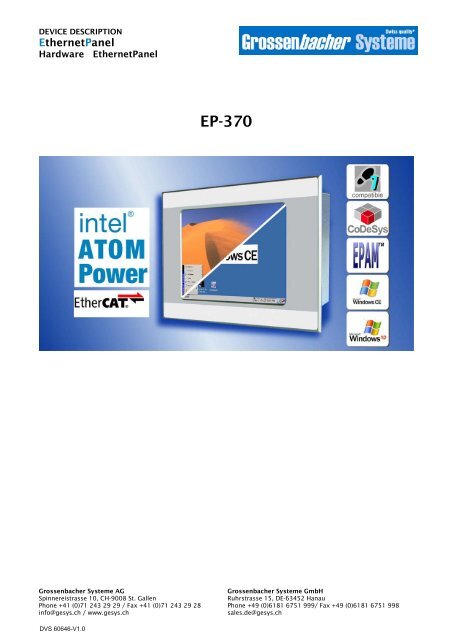
DEVICE DESCRIPTION<br />
EthernetPanel<br />
Hardware EthernetPanel<br />
<strong>Grossenbacher</strong> <strong>Systeme</strong> <strong>AG</strong><br />
Spinnereistrasse 10, CH-9008 St. Gallen<br />
Phone +41 (0)71 243 29 29 / Fax +41 (0)71 243 29 28<br />
info@gesys.ch / www.gesys.ch<br />
<strong>EP</strong>-<strong>370</strong><br />
<strong>Grossenbacher</strong> <strong>Systeme</strong> GmbH<br />
Ruhrstrasse 15, DE-63452 Hanau<br />
Phone +49 (0)6181 6751 999/ Fax +49 (0)6181 6751 998<br />
sales.de@gesys.ch
EthernetPanel<br />
Hardware EthernetPanel<br />
Copyright<br />
Keep documentation for future use!<br />
This documentation is the intellectual property of <strong>Grossenbacher</strong> <strong>Systeme</strong> <strong>AG</strong>, which also has<br />
the exclusive copyright. Any modification of the content, duplication or reprinting of this<br />
documentation, as well as any distribution to third parties can only be made with the express<br />
permission of <strong>Grossenbacher</strong> <strong>Systeme</strong> <strong>AG</strong>.<br />
<strong>Grossenbacher</strong> <strong>Systeme</strong> <strong>AG</strong> does not accept any liability for damages arising from the use of<br />
any incorrect or incomplete information contained in this documentation or any information missing<br />
therefrom.<br />
<strong>Grossenbacher</strong> <strong>Systeme</strong> <strong>AG</strong> reserves the right to make complete or partial modifications to this<br />
document.<br />
All brand and product names are trademarks or registered trademarks of the owner concerned<br />
DVS 60646 V1.0 © 2010 by <strong>Grossenbacher</strong> <strong>Systeme</strong> <strong>AG</strong>
Proper use<br />
EthernetPanel<br />
Hardware EthernetPanel<br />
The device must only be used for the applications specified in the<br />
device description and only in conjunction with the components<br />
recommended by Moeller GmbH.<br />
Warning<br />
Trouble-free and safe operation of the product can only be ensured if<br />
the measures relating to proper transport, storage, assembly,<br />
installation and careful operation are strictly observed.<br />
The device must not be switched on when it is covered with<br />
condensation. When changing its location from cold to warm allow the<br />
device to acclimatize to the new conditions before commissioning.<br />
No warranty claims will be recognized for faults arising from the<br />
improper handling of the device.<br />
The device should not be used for the implementation of any safety<br />
functions relating to the protection of personnel and machinery.<br />
No liability is accepted for claims for damages arising from a failure or<br />
functional defect in the device.<br />
All data specified in this document does not represent guaranteed<br />
specifications in the legal sense.<br />
© 2010 by <strong>Grossenbacher</strong> <strong>Systeme</strong> <strong>AG</strong> DVS 60646 V1.0 3
EthernetPanel<br />
Hardware EthernetPanel<br />
Safety instructions for the user<br />
This device description contains the information required for the<br />
proper use of the products described therein. Sections 1 to 10 address<br />
technically qualified personnel and Section onwards addresses<br />
personnel not requiring any technical knowledge.<br />
Qualified personnel in the sense of the safety instructions given in this<br />
device description or on the product itself are persons who:<br />
as engineering personnel are either familiar with the safety concepts of<br />
automation,<br />
or as operating personnel, are instructed in the use of automation<br />
components and are familiar with the contents of this device<br />
description relating to the operation of the device,<br />
or as commissioning or service personnel are suitably trained for the<br />
repair of automation devices and are authorized to commission circuits<br />
and devices/systems in accordance with standard safety engineering<br />
principles.<br />
4 DVS 60646 V1.0 © 2010 by <strong>Grossenbacher</strong> <strong>Systeme</strong> <strong>AG</strong>
Contents<br />
EthernetPanel<br />
Hardware EthernetPanel<br />
1 Explanation of symbols................................................. 7<br />
2 Introduction.................................................................... 9<br />
3 Device Versions ........................................................... 11<br />
3.1 Specification ......................................................................... 11<br />
3.2 Accessories ..........................................................................12<br />
4 Features........................................................................ 13<br />
5 Commissioning............................................................ 15<br />
5.1 Overview of connections ......................................................15<br />
5.2 Connecting the power supply ...............................................15<br />
5.3 Power Fail and UPS .............................................................16<br />
5.4 Fuse .....................................................................................16<br />
5.5 Battery ..................................................................................16<br />
5.6 Preparing the shield connections .........................................17<br />
5.7 Connecting the Ethernet.......................................................18<br />
5.8 Connecting the USB-Interface..............................................18<br />
5.9 Connection for COM1 serial interface (RS232)....................19<br />
5.10 CAN interface...................................................................19<br />
5.11 Inserting / Removing the CompactFlash.......................22<br />
5.12 Inserting / Removing the SDCARD ..............................22<br />
5.13 Expansion PC/104-Slot....................................................22<br />
5.14 Expansion PC/104-Slot....................................................22<br />
6 Operation...................................................................... 23<br />
6.1 Startup / Shutdown behaviour ..............................................23<br />
6.2 System-Settings ...................................................................23<br />
7 Mounting instructions ................................................. 25<br />
7.1 General mounting instructions..............................................25<br />
7.2 Mounting in the front panel - General...................................25<br />
7.3 Front panel cutout 5,7“ to 15“ ..............................................26<br />
7.4 Mechanical dimensions - Frontside 5,7“ to 15“....................29<br />
7.5 Mechanical dimensions - Rear side 5,7“ to 15 .....................32<br />
8 Notes on the touch-screen.......................................... 39<br />
8.1 Basic touch-screen function .................................................39<br />
9 Backlight, contrast....................................................... 41<br />
9.1 Contrast................................................................................41<br />
9.2 Backlight...............................................................................41<br />
9.3 Diagnostics...........................................................................41<br />
10 Maintenance and repair............................................... 43<br />
11 Technical data.............................................................. 45<br />
12 Disposal........................................................................ 47<br />
13 EU Conformity and Standards.................................... 49<br />
14 Revision history........................................................... 51<br />
15 Alphabetical index ....................................................... 53<br />
© 2010 by <strong>Grossenbacher</strong> <strong>Systeme</strong> <strong>AG</strong> DVS 60646 V1.0 5
EthernetPanel<br />
Hardware EthernetPanel<br />
6 DVS 60646 V1.0 © 2010 by <strong>Grossenbacher</strong> <strong>Systeme</strong> <strong>AG</strong>
1 Explanation of symbols<br />
EthernetPanel<br />
Hardware EthernetPanel<br />
Danger warnings<br />
The following information is for your personal safety and the prevention of<br />
damage to the device described or connected devices.<br />
Safety instructions and warnings for the prevention of danger to the life and<br />
health of users or service personnel, and for the prevention of damage are<br />
highlighted in this document by the following pictograms. “Warning” and<br />
“Information” pictograms are shown in this document.<br />
Warnings indicate the following:<br />
Death, serious injury or substantial material damage may occur if the related<br />
safety measures are not implemented.<br />
The individual “Warning” pictograms have the following meaning:<br />
Caution! General!<br />
An instruction to be observed in order to ensure protection<br />
against hazards and the safe operation of the device. The<br />
specified procedure should be observed.<br />
Caution! Electric shock!<br />
Persons may be exposed to dangerous voltages that occur<br />
in electrical systems. There is a danger of electric shock if a<br />
live part is touched.<br />
Caution! Observe ESD measures!<br />
Electrostatic discharge may destroy electronic components.<br />
Information pictograms indicate the following:<br />
Important information about the product or the relevant section of the<br />
document, requiring the particular attention of the reader.<br />
The “Information” pictogram has the following meaning:<br />
Indicates important and instructional information.<br />
© 2010 by <strong>Grossenbacher</strong> <strong>Systeme</strong> <strong>AG</strong> DVS 60646 V1.0 7
EthernetPanel<br />
Hardware EthernetPanel<br />
8 DVS 60646 V1.0 © 2010 by <strong>Grossenbacher</strong> <strong>Systeme</strong> <strong>AG</strong>
2 Introduction<br />
EthernetPanel<br />
Hardware EthernetPanel<br />
The new generation of EthernetPanel <strong>EP</strong>-<strong>370</strong> devices features the 1GHz<br />
class continously from 5,7” up to 15” within the openAutomation concept of<br />
<strong>Grossenbacher</strong> <strong>Systeme</strong> <strong>AG</strong>. They are based on the Intel Atom 1,1GHzx86-CPU<br />
with WindowsCE/XP/XPe and Ethernet on-board.<br />
In the basic configuration the device can be used as „HMI“ or as a user<br />
programmable „HMI-Open“ with 2xEthernet and USB onboard. The<br />
fieldbus interfaces EtherCAT, CANopen, ProfibusDP-Master/Slave or MPI<br />
are available optionally.<br />
With CoDeSys V3 IEC-61131 Soft-PLC the device can be used as "HMI-<br />
Control" with EtherCAT-Master, Codesys TargetVisu, WebVisu, integrated<br />
Soft-PLC and with CoDeSys Soft-Motion. Alternatively the ST<strong>EP</strong>7®<br />
compatible Soft-PLC AT-S7 is available, which can be programmed with<br />
standard SIMATIC Manager via Ethernet.<br />
An exchangeable Compact-Flash is used as mass storage device.<br />
Without moving parts the devices are “at home” in rugged environment!<br />
For fast, intuitive and fatigue free operation two approved touch-screen<br />
technologies are available: the service free infrared touch-screen with<br />
scratch resistant safety glass or the seamless resistive touch-screen.<br />
Features:<br />
• WindowsCE<br />
• Touchscreen<br />
• Intel Atom CPU 1,1 or 1,6GHz<br />
• 2xEthernet onboard<br />
• Exchangeable CompactFlash and SDCARD<br />
• EtherCAT, Profibus, MPI, CANopen (Option)<br />
• Soft-Motion (Option)<br />
The devices can be installed in control panels or control desks without any<br />
problem. The devices are not designed for mobile use.<br />
This device description is a reference for the technical data, installation,<br />
terminals, commissioning, operation, and maintenance of all EthernetPanel<br />
versions.<br />
Additional documentation:<br />
System description WindowsCE DVS 49631<br />
System description Windows XP DVS 52696<br />
System description CoDeSys V3 Soft-PLC DVS 60742<br />
© 2010 by <strong>Grossenbacher</strong> <strong>Systeme</strong> <strong>AG</strong> DVS 60646 V1.0 9
EthernetPanel<br />
Hardware EthernetPanel<br />
10 DVS 60646 V1.0 © 2010 by <strong>Grossenbacher</strong> <strong>Systeme</strong> <strong>AG</strong>
3 Device Versions<br />
EthernetPanel<br />
Hardware EthernetPanel<br />
In this chapter all device versions of the EthernetPanels and available<br />
accessories are specified.<br />
3.1 SPECIFICATION<br />
General features of all device versions:<br />
Processor: 1.1GHz / 1.6GHz Intel ATOM x86 CPU<br />
Memory: 512MB /1GB<br />
Mass storage: CompactFlash-Slot, SDCARD-Slot<br />
Interfaces: 2 x Ethernet GBit<br />
4 x USB Master<br />
1 x RS232<br />
1 x CAN<br />
Power supply: 24VDC<br />
<strong>EP</strong>-<strong>370</strong>-BOX-000<br />
<strong>EP</strong>-<strong>370</strong>-05I-000<br />
<strong>EP</strong>-<strong>370</strong>-07I-000<br />
<strong>EP</strong>-<strong>370</strong>-10I-000<br />
<strong>EP</strong>-<strong>370</strong>-10R-000<br />
<strong>EP</strong>-<strong>370</strong>-12I-000<br />
<strong>EP</strong>-<strong>370</strong>-12R-000<br />
<strong>EP</strong>-<strong>370</strong>-15I-000<br />
<strong>EP</strong>-<strong>370</strong>-15R-000<br />
Ord.No : 50 81 389<br />
EthernetPanel BOX for DIN rail mounting<br />
Ord.No : 50 81 383<br />
EthernetPanel 5,7” TFT 640x480 256k colours<br />
Infrared touch-screen<br />
Ord.No : 50 81 382<br />
EthernetPanel 7,5” TFT 640x480 256k colours<br />
Infrared touch-screen<br />
Ord.No : 50 81 381<br />
EthernetPanel 10,4” TFT 640x480 256k colours<br />
Infrared touch-screen<br />
Ord.No : 50 81 387<br />
EthernetPanel 10,4” TFT 640x480 256k colours<br />
Resistive touch-screen<br />
Ord.No : 50 81 380<br />
EthernetPanel 12” TFT 800x600 256k colours<br />
Infrared touch-screen<br />
Ord.No : 50 81 388<br />
EthernetPanel 12” TFT 800x600 256k colours<br />
Resistive touch-screen<br />
Ord.No : 50 81 379<br />
EthernetPanel 12” TFT 1024x786 256k colours<br />
Infrared touch-screen<br />
Ord.No : 50 81 386<br />
EthernetPanel 12” TFT 1024x768 256k colours<br />
Resistive touch-screen<br />
© 2010 by <strong>Grossenbacher</strong> <strong>Systeme</strong> <strong>AG</strong> DVS 60646 V1.0 11
EthernetPanel<br />
Hardware EthernetPanel<br />
3.2 ACCESSORIES<br />
Runtime-System Ord.No: 50 56 993<br />
RTS HMI CEx86 QAZ510P<br />
WindowsCE6 Professional and <strong>EP</strong>AM-RTS<br />
preinstalled on CompactFlash<br />
CompactFlash<br />
SDCARD<br />
Connector for power<br />
supply<br />
Profibus-DPM<br />
(PC104)<br />
Profibus-DPS/MPI<br />
(PC104)<br />
2.CAN (PC104)<br />
Ord.No: 50 56 994<br />
RTS HMI CEx86 QAZ510P 3S V3<br />
WindowsCE6 Professional, <strong>EP</strong>AM-RTS and<br />
Codesys-RTS V3 preinstalled on CompactFlash<br />
Ord.No: 50 56 995<br />
RTS HMI CEx86 QAZ510P AT-S7<br />
WindowsCE6 Professional, <strong>EP</strong>AM-RTS and AT-S7-<br />
RTS preinstalled on CompactFlash<br />
Ord.No: 50 56 996<br />
RTS HMI WindowsXP POSReady QAZ510P HD<br />
WindowsXP embedded preinstalled on Harddisk<br />
Ord.No: 50 56 997<br />
RTS HMI WindowsXP POSReady QAZ510P CF<br />
WindowsXP embedded preinstalled on<br />
CompactFlash<br />
Ord.No : 50 56 825<br />
CompactFlash 256MB with WindowsCE Bootloader<br />
Ord.No : 50 56 827<br />
CompactFlash 1GB with WindowsCE Bootloader<br />
Ord.No: 32 01 352<br />
SDCARD 512MB, INDUSTRIAL<br />
Ord.No: 32 01 353<br />
SDCARD 1GB, INDUSTRIAL<br />
Ord.No : 12 17 017<br />
3pol Phoenix Contact, MSTB2.5/3-ST-5.08<br />
Ord.No : 32 12 860<br />
Profibus DP-Master; configurable Master/Slave/MPI<br />
Ord.No : 32 12 859<br />
Profibus DP-Slave/MPI<br />
Ord.No : 32 12 890<br />
2.CAN<br />
12 DVS 60646 V1.0 © 2010 by <strong>Grossenbacher</strong> <strong>Systeme</strong> <strong>AG</strong>
4 Features<br />
Feature Comment<br />
Display<br />
Display Size 5,7“ / 7,5“ / 10,4“ / 12.1“ / 15”<br />
EthernetPanel<br />
Hardware EthernetPanel<br />
Type TFT 256k Colours<br />
Touch-screen Infrared touch-screen Resolution 5,7“: 45 x 33 / 7,5“: 57 x 43<br />
10,4“: 81 x 61 …/… 12“: 93 x 71<br />
15“: 115 x 87<br />
Resistive touch- Resolution 12 Bit (0-4096)<br />
screen<br />
Realtime clock Yes Battery-backed<br />
Processor Type Intel ATOM<br />
Clock 1.1GHz/1.6GHz<br />
Mass storage CompactFlash Type I and II (Microdrives supported)<br />
Memory SDRAM MB 512MB / 1GB<br />
Retain memory kB 256kB 1<br />
Exchangeable SDCARD<br />
Type SD-Card-Slot or Memorystick (optional via USB)<br />
memory<br />
Memorystick<br />
Interfaces COM1 Type RS232, max. 115 kBit/s<br />
COM2 Type RS232 internally for touch-screen<br />
Ethernet 1-2 Type 10 / 100 / 1000 MBit/s<br />
USB 1-4 (2.0) Type 1.5 / 12 / 480 MBit/s<br />
Keyboard Type Optional via USB<br />
Mouse Type Optional via USB<br />
PC/104 Type 8bit PC/104 Slot<br />
(installation of modules only factory made) 2<br />
Expansion-<br />
Count 1 Slot<br />
Slot<br />
Power supply Type 24VDC, NOT isolated<br />
Device cooling Type passive (fanless)<br />
1 Retain data will be saved on power fail to CompactFlash<br />
2 Only a subset of PC-104<br />
CompactFlash memory media are NOT suitable for<br />
cyclical data logging due to the limited number of write<br />
cycles (normally 1,000,000).<br />
© 2010 by <strong>Grossenbacher</strong> <strong>Systeme</strong> <strong>AG</strong> DVS 60646 V1.0 13
EthernetPanel<br />
Hardware EthernetPanel<br />
14 DVS 60646 V1.0 © 2010 by <strong>Grossenbacher</strong> <strong>Systeme</strong> <strong>AG</strong>
5 Commissioning<br />
5.1 OVERVIEW OF CONNECTIONS<br />
1<br />
2 3 4 5 6<br />
EthernetPanel<br />
Hardware EthernetPanel<br />
No. Element Description<br />
1 Function earth<br />
2 24VDC power supply � Chap. 5.2<br />
3 COM1 � Chap. 5.9<br />
4 CAN � Chap. 5.10<br />
5 4xUSB � Chap. 5.8<br />
6 2xEthernet � Chap. 5.7<br />
7 SDCARD-Slot � Chap. 5.12<br />
8 Battery � Chap.5.5<br />
9 CompactFlash � Chap. 5.11<br />
10 PC/104 Steckplatz � Chap. 5.13<br />
5.2 CONNECTING THE POWER SUPPLY<br />
The EthernetPanel devices belongs to protection class 3. The system power<br />
supply must be provided with a 24VDC SELV voltage (� Section 11). The<br />
power supply is NOT isolated. The GND connection is directly connected to<br />
the housing potential. The device is protected with a fuse (note<br />
disconnection capacity � Section 11). A reverse polarity protective device is<br />
used to protect the device in the event of reversed poles. Operation,<br />
however, is only possible if the connection was made correctly.<br />
Connections for the EthernetPanel must comply with specific, local<br />
regulations.<br />
© 2010 by <strong>Grossenbacher</strong> <strong>Systeme</strong> <strong>AG</strong> DVS 60646 V1.0 15<br />
10<br />
7<br />
8<br />
9
EthernetPanel<br />
Hardware EthernetPanel<br />
The connection must be made as follows:<br />
1. The cross-section of the power supply cable must be at least 0.75 mm²<br />
and a maximum of 2.5 mm².<br />
2. A flexible lead or wire can be used for the connection.<br />
3. The current consumption (� Section 11) must be taken into account<br />
when implementing the power supply.<br />
4. The functional earth is not compulsory for operation. But it can help to<br />
avoid disturbance caused by potential differences.<br />
5. The GND connection is directly connected to the housing potential<br />
6. For safety reasons the wires should be fixed together near by the<br />
connector<br />
The plug connector (socket connector with screw terminals) is supplied with<br />
the device for connection.<br />
Connector assignment<br />
Designation Function<br />
+24 VDC +24VDC power supply<br />
reserved !<br />
In the event of reverse connection and simultaneous<br />
connection of a further 0V connection, e.g. GND<br />
connection of the COM1 interface, the fault current flows<br />
via this OV connection. If the housing is not lying well set<br />
on the OV potential, the result can be destruction of the<br />
device or of the external components!<br />
For safety reasons the wires should be fixed together<br />
near by the connector.<br />
5.3 POWER FAIL AND UPS<br />
The device includes a power fail functionality. The power fail mechanism<br />
prevents the loss of retain data if a Soft-PLC (Codesys or AT-S7) is used.<br />
The retain data are stored on CompactFlash when the PLC is shutting down<br />
and are read out again when the PLC starts up. (for details s.a. System<br />
description Codesys Soft-PLC or AT-S7)<br />
The standard integrated UPS-solution can bridge brownouts up to about 5s.<br />
5.4 FUSE<br />
reserved<br />
0 V 0V power supply<br />
The device is protected with a fuse internally. The fuse can not be changed<br />
by the user.<br />
5.5 BATTERY<br />
The internal battery is used for backing up the real-time clock and has a<br />
lifetime of at least 5 years. The battery can be replaced by the user. (Type:<br />
CR2032).<br />
24VDC 0VDC<br />
(plug connector: 3pol Phoenix MSTB2.5/3-ST-<br />
5.08, RM 5.08mm, Phönix Ord.Nr 1757022)<br />
16 DVS 60646 V1.0 © 2010 by <strong>Grossenbacher</strong> <strong>Systeme</strong> <strong>AG</strong>
5.6 PR<strong>EP</strong>ARING THE SHIELD CONNECTIONS<br />
EthernetPanel<br />
Hardware EthernetPanel<br />
The preparation of the data and signal cables is an important factor for the<br />
electromagnetic compatibility (EMC) of the EthernetPanel, both in terms of<br />
interference immunity and emission.<br />
The RS232 and CAN interface are connected via D-Subminiature plug<br />
connectors in accordance with DIN 41652. Only use metal or metallised<br />
connector casings with a cable clamp for strain relief fastened or clamped<br />
on the connector. The clamping of the cable shield ensures an optimum<br />
contact area and a low impedance connection with the connector casing of<br />
the EthernetPanel.<br />
The following procedure is recommended for making the low-impedance<br />
connection for the cable shield:<br />
1. Strip the cable.<br />
2. Shorten the exposed shield braid by approx. 3 cm.<br />
3. Turn back the braid over the cable sheath.<br />
4. Use a heat shrinkable tubing or rubber grommet to cover the exposed<br />
cable sheath with the folded back shield braid so that 5 to 8 mm of<br />
exposed cable shield is left at the sheath end and is cleanly covered at<br />
the back.<br />
5. Fit the connector<br />
6. The cable is then fastened at the exposed shield braid and the cable<br />
sheath below it directly underneath the cable clamp strap of the<br />
connector casing.<br />
Shield braid pulled<br />
back over the<br />
cable sheath<br />
Heat shrinkable<br />
tubing for covering<br />
the shield braid<br />
Metal or metallised<br />
connector casing<br />
Strap for cable clamp<br />
and contacting of the<br />
cable shield with the<br />
connector casing<br />
Fastening<br />
screws<br />
Metallic<br />
connector shroud<br />
D-subminiature connector<br />
Connection work should be carried out with special care<br />
in order to ensure trouble-free operation.<br />
The EMC values stated in the technical data can only be<br />
guaranteed if the cables are prepared according to the<br />
following specifications.<br />
© 2010 by <strong>Grossenbacher</strong> <strong>Systeme</strong> <strong>AG</strong> DVS 60646 V1.0 17
EthernetPanel<br />
Hardware EthernetPanel<br />
5.7 CONNECTING THE ETHERNET<br />
The Ethernet-Interface is compatible with standard IEEE 802.3<br />
(10/100/1000BASE-T).<br />
The network connection is implemented via a Cat 5e cable with shield and<br />
RJ45 connectors. The maximum cable length and transfer speed is limited<br />
by the cable quality in EIA/TIA 568 TSB-36. Cable lengths up to 100m are<br />
possible.<br />
Two diagnosis LEDs are available:<br />
Orange: LINK (connection to HUB or to another device)<br />
Green: ACT (sending or receiving)<br />
Cables connected to the Ethernet must be laid separately from the lowvoltage<br />
cables.<br />
Connector assignment<br />
RJ45<br />
connector<br />
1<br />
2<br />
3<br />
4<br />
5<br />
6<br />
7<br />
8<br />
To ensure disturbance-free operation, it is strongly<br />
recommended to use network cables with shield.<br />
Pin No. Signal Description<br />
1 TXD+<br />
2 TXD-<br />
3 RXD+<br />
4 -<br />
5 -<br />
6 RXD-<br />
Socket, 8pole 7 -<br />
RJ45 8 -<br />
5.8 CONNECTING THE USB-INTERFACE<br />
The USB Interface is compatible to USB-standard Version 2.0<br />
The use of the USB-Interface requires support by the operating system.<br />
Cables connected to the USB must be laid separately from the low-voltage<br />
cables.<br />
18 DVS 60646 V1.0 © 2010 by <strong>Grossenbacher</strong> <strong>Systeme</strong> <strong>AG</strong><br />
ACT<br />
3<br />
LINK
1 2 3 4 5<br />
6 7 8 9<br />
5<br />
1 2 3 4 5<br />
6 7 8 9<br />
6<br />
EthernetPanel<br />
Hardware EthernetPanel<br />
5.9 CONNECTION FOR COM1 SERIAL INTERFACE (RS232)<br />
The serial Interface COM1 is PC-compatible. This interface is not isolated.<br />
The GND connection is implemented directly on the housing potential (�<br />
Section 11).<br />
Connector Pin No. Signal Description<br />
6<br />
7<br />
8<br />
9<br />
1<br />
2<br />
3<br />
4<br />
5<br />
1<br />
2<br />
3<br />
4<br />
5<br />
6<br />
DCD<br />
RXD<br />
TXD<br />
DTR<br />
GND<br />
DSR<br />
7 RTS<br />
Connector<br />
9pole<br />
8 CTS<br />
SubD 9 RI<br />
Cables connected to the programming interface (Ethernet or serial) must be<br />
laid separately from the low-voltage cables.<br />
5.10 CAN INTERFACE<br />
To ensure disturbance-free operation, it is strongly<br />
recommended to use cables with shield.<br />
The communication interface is defined in accordance with the CiA CAN<br />
Specification V2.0 part B. The fully-integrated CAN unit supports the sending<br />
and receiving of frames with an 11-bit identifier. The type of configuration<br />
selected depends on the software protocol. The baud rate can be selected in<br />
a wide range, and only the standard CiA baud rates are implemented.<br />
Connect<br />
or<br />
The CAN interface is NOT isolated.<br />
The max. baud rate is 1MBit/s.<br />
6<br />
7<br />
8<br />
9<br />
1<br />
2<br />
3<br />
4<br />
5<br />
CAN connector<br />
Sub-D 9 Pole male<br />
Pin No. Assignme<br />
nt<br />
Function<br />
1 -<br />
2 CAN<br />
LOW<br />
Negative data signal<br />
3 GND Signal Ground (ground potential)<br />
4 -<br />
5 -<br />
6 GND Signal Ground (ground potential)<br />
7 CAN<br />
HIGH<br />
Positive data signal<br />
8 -<br />
9 -<br />
Case Case Cable shield<br />
© 2010 by <strong>Grossenbacher</strong> <strong>Systeme</strong> <strong>AG</strong> DVS 60646 V1.0 19
EthernetPanel<br />
Hardware EthernetPanel<br />
Wiring instructions<br />
The terminating resistor must be implemented externally,<br />
e.g. in the connector, and is not part of the device.<br />
The CAN connector is not provided with a supply for<br />
third-party devices.<br />
A detailed description of the wiring is provided in the<br />
“Codesys Soft-PLC” system description<br />
The stations on the bus system are connected via fieldbus lines complying<br />
with ISO 11898. The cables must accordingly have the following electrical<br />
characteristics:<br />
Parameter Abbreviation Unit Value Value Value Note<br />
min. nom. max.<br />
Impedance Z Ω 108 120 132 Measured between two<br />
signal lines<br />
Specific<br />
resistance<br />
mΩ/m 70 For the receiver<br />
module, the differential<br />
voltage on the bus<br />
cable depends on cable<br />
resistance between it<br />
and the sender<br />
Cable delay ns/m 5 The mininum delay<br />
between to points on<br />
the bus is 0. The<br />
maximum delay is<br />
determined by the bit<br />
timing and the delays of<br />
the sender and receiver<br />
circuits<br />
The figure shows the minimum wiring with shielding between two bus<br />
stations with the Sub-D connector as an example. A bus terminating resistor<br />
(120 Ohm between Pin 2 and Pin 7 of the Sub-D connector) must be<br />
connected at the beginning and the end of each CAN bus. Do not swap<br />
around the two signal wires!<br />
Interface 1<br />
Protective ground<br />
Shield<br />
Protective ground<br />
20 DVS 60646 V1.0 © 2010 by <strong>Grossenbacher</strong> <strong>Systeme</strong> <strong>AG</strong>
EthernetPanel<br />
Hardware EthernetPanel<br />
Pin 3 and 6 (CAN_GND) are both connected internally with the CAN<br />
Ground. Pins 4, 5 and 8 must not be connected! The CAN bus driver is fed<br />
internally.<br />
Baud rate and cable lengths<br />
Shield Inside: twisted pair cable<br />
Station 1 Station n<br />
Baud rate Max. length<br />
20kBit/sec 2500m<br />
25kBit/sec 2000m<br />
50kBit/sec 1000m<br />
100kBit/sec 650m<br />
125kBit/sec 500m<br />
250kBit/sec 250m<br />
500kBit/sec 100m<br />
1Mbit/sec 6m<br />
bus terminating resistor<br />
© 2010 by <strong>Grossenbacher</strong> <strong>Systeme</strong> <strong>AG</strong> DVS 60646 V1.0 21
EthernetPanel<br />
Hardware EthernetPanel<br />
5.11 INSERTING / REMOVING THE COMPACTFLASH<br />
The EthernetPanel series devices use a CompactFlash card as mass<br />
storage device. The CompactFlash-Slot is placed on the upper side of the<br />
dives. It is strongly recommened to use only CompactFlash cards<br />
obtained from the original accessories.<br />
The CompactFlash must only be fitted or removed<br />
with the device power supply switched off.<br />
Otherwise data can be lossed.<br />
The device cannot run without a CompactFlash card.<br />
Correct functioning of the device can only be ensured<br />
by using CompactFlash cards obtained from the<br />
original accessories.<br />
5.12 INSERTING / REMOVING THE SDCARD<br />
The EthernetPanel series devices use a SDCARD slot for removable mass<br />
storage devices. SD and SDHC cards are supported. (s.a. accessories)<br />
SDCARDs may be removed during operation. To avoid data loss it is<br />
recommended to use the operating system functionality to replace the<br />
removeable devices. (s.a. system description WindowsCE/XP)<br />
5.13 EXPANSION PC/104-SLOT<br />
The EthernetPanels devices can carry one PC/104 module (e.g. Profibus<br />
DP-Master/Slave or MPI) which must be inserted factory made. The PC/104<br />
interface is compatible to standard 8-bit ISA-Bus, but has a limited<br />
functionality. Only PC-104 modules out of the original accessory range can<br />
be used. The following modules are supported:<br />
Profibus DP (Master, Slave, MPI) no restrictions<br />
2 nd CAN interface no restrictions<br />
4xRS232 mutual exlusive with Power Fail<br />
functionality (see chapter 5.3)<br />
The PC/104-module must be inserted factory made.<br />
5.14 EXPANSION PC/104-SLOT<br />
Optinal a 2,5” Sata hard disk is available for the device. This option must be inserted factory made. The hard<br />
disk can be installed instead of the PC104 module.<br />
22 DVS 60646 V1.0 © 2010 by <strong>Grossenbacher</strong> <strong>Systeme</strong> <strong>AG</strong>
6 Operation<br />
6.1 STARTUP / SHUTDOWN BEHAVIOUR<br />
EthernetPanel<br />
Hardware EthernetPanel<br />
After power on the EthernetPanel boots the installed operating system from<br />
the CompactFlash. During boot up the BIOS self tests will be done.<br />
The Touch-controller starts with two beeps.<br />
6.2 SYSTEM-SETTINGS<br />
The EthernetPanels have a PC/AT compatible CPU. The standard BIOS<br />
settings are available. The BIOS-settings are preconfigured factory made<br />
and should not be changed by the user.<br />
For a detailed description of the system-settings on<br />
operating system level please refer to the<br />
corresponding software-documentation. (e.g. System<br />
description WindowsCE/XP)<br />
© 2010 by <strong>Grossenbacher</strong> <strong>Systeme</strong> <strong>AG</strong> DVS 60646 V1.0 23
EthernetPanel<br />
Hardware EthernetPanel<br />
24 DVS 60646 V1.0 © 2010 by <strong>Grossenbacher</strong> <strong>Systeme</strong> <strong>AG</strong>
7 Mounting instructions<br />
7.1 GENERAL MOUNTING INSTRUCTIONS<br />
EthernetPanel<br />
Hardware EthernetPanel<br />
All EthernetPanel series devices are mounted from the front, i.e. in a control<br />
panel. They are fastened from the rear with the supplied fixing frame and 4<br />
securing nuts.<br />
All EthernetPanel series devices can be operated up to a maximum ambient<br />
temperature of 50°C (� Section 11). The ambient temperature stated<br />
applies to the area 5cm above the device, if it is mounted vertically with<br />
unimpeded air convection and a maximum operating height of 2000m above<br />
sea level.<br />
The device can be mounted in an enclosure if the ambient temperature is<br />
taken into consideration. Provide a wall clearance of at least 50 mm on all<br />
sides of the housing, so that sufficient air circulation is ensured. A minimum<br />
clearance of 75 mm from active elements such as load current supply,<br />
transformers etc. must be ensured.<br />
Avoid the exposure of the flat screen to direct sunlight. The radiation from<br />
the sun (UV component) reduces the lifespan of the LCD display.<br />
The following must be ensured in order to prevent the<br />
device from overheating during operation:<br />
- The cooling slots must always be free in order to<br />
ensure the proper cooling of the system.<br />
- Avoid the exposure of the flat screen to direct<br />
sunlight.<br />
- The mounting angle must not exceed ± 35° from<br />
the vertical<br />
If these conditions cannot be met, the mounting of an<br />
external fan is recommended.<br />
7.2 MOUNTING IN THE FRONT PANEL - GENERAL<br />
1. The front seal must be inlayed in the frontpanel slot and the two ends<br />
must be justified at the lower side<br />
2. Push the EthernetPanel from the front into the cutout of the front<br />
panel.<br />
3. Secure the device from the rear with the supplied fixing frame. For this<br />
use the 4 securing nuts which should be tightened evenly from the rear<br />
until the front frame is flush with the front panel all round.<br />
Ensure that the seal is fitted correctly on the front panel.<br />
For devices with a round seal the two ends must be at<br />
the lower side of the device and should fit together<br />
without a gap.<br />
Avoid tightening torques of greater than 0.5 Nm as this<br />
could otherwise damage the device.<br />
The thickness of the front panel must not exceed 5 mm.<br />
© 2010 by <strong>Grossenbacher</strong> <strong>Systeme</strong> <strong>AG</strong> DVS 60646 V1.0 25
EthernetPanel<br />
Hardware EthernetPanel<br />
7.3 FRONT PANEL CUTOUT 5,7“ TO 15“<br />
Tolerance for panel cutout +0/-1 mm<br />
The thickness of the front panel must not exceed 5 mm.<br />
Front panel cutout - 5.7"<br />
Front panel cutout – 7.5"<br />
26 DVS 60646 V1.0 © 2010 by <strong>Grossenbacher</strong> <strong>Systeme</strong> <strong>AG</strong>
EthernetPanel<br />
Hardware EthernetPanel<br />
Front panel cutout - 10.4“<br />
Front panel cutout - 12.1“<br />
© 2010 by <strong>Grossenbacher</strong> <strong>Systeme</strong> <strong>AG</strong> DVS 60646 V1.0 27
EthernetPanel<br />
Hardware EthernetPanel<br />
Front panel cutout - 15“<br />
28 DVS 60646 V1.0 © 2010 by <strong>Grossenbacher</strong> <strong>Systeme</strong> <strong>AG</strong>
7.4 MECHANICAL DIMENSIONS - FRONTSIDE 5,7“ TO 15“<br />
Front dimensions - 5,7"<br />
Front dimensions – 7,5"<br />
EthernetPanel<br />
Hardware EthernetPanel<br />
© 2010 by <strong>Grossenbacher</strong> <strong>Systeme</strong> <strong>AG</strong> DVS 60646 V1.0 29
EthernetPanel<br />
Hardware EthernetPanel<br />
Front dimensions - 10.4“<br />
Front dimensions – 12,1“<br />
30 DVS 60646 V1.0 © 2010 by <strong>Grossenbacher</strong> <strong>Systeme</strong> <strong>AG</strong>
Front dimensions – 15“<br />
EthernetPanel<br />
Hardware EthernetPanel<br />
© 2010 by <strong>Grossenbacher</strong> <strong>Systeme</strong> <strong>AG</strong> DVS 60646 V1.0 31
EthernetPanel<br />
Hardware EthernetPanel<br />
7.5 MECHANICAL DIMENSIONS - REAR SIDE 5,7“ TO 15”<br />
Dimensions rear side - 5.7“<br />
32 DVS 60646 V1.0 © 2010 by <strong>Grossenbacher</strong> <strong>Systeme</strong> <strong>AG</strong>
Dimensions rear side - 7.5"<br />
EthernetPanel<br />
Hardware EthernetPanel<br />
© 2010 by <strong>Grossenbacher</strong> <strong>Systeme</strong> <strong>AG</strong> DVS 60646 V1.0 33
EthernetPanel<br />
Hardware EthernetPanel<br />
Dimensions rear side - 10.4“<br />
34 DVS 60646 V1.0 © 2010 by <strong>Grossenbacher</strong> <strong>Systeme</strong> <strong>AG</strong>
Dimensions rear side - 12.1“<br />
EthernetPanel<br />
Hardware EthernetPanel<br />
© 2010 by <strong>Grossenbacher</strong> <strong>Systeme</strong> <strong>AG</strong> DVS 60646 V1.0 35<br />
15“
EthernetPanel<br />
Hardware EthernetPanel<br />
Dimensions rear side - 15“<br />
36 DVS 60646 V1.0 © 2010 by <strong>Grossenbacher</strong> <strong>Systeme</strong> <strong>AG</strong>
Dimensions rear side - BOX<br />
EthernetPanel<br />
Hardware EthernetPanel<br />
© 2010 by <strong>Grossenbacher</strong> <strong>Systeme</strong> <strong>AG</strong> DVS 60646 V1.0 37
8 Notes on the touch-screen<br />
8.1 BASIC TOUCH-SCREEN FUNCTION<br />
EthernetPanel<br />
Hardware EthernetPanel<br />
Devices with infrared touch-screen<br />
The touch-screen operates on the active light matrix principle in the infrared<br />
range. Interrupting this light matrix at any point will initiate an operation<br />
if a touch activated screen element was touched (e.g. a button).<br />
A timeout is initiated if the light matrix is interrupted for longer than approx.<br />
7s. The touch panel then switches to the “non-actuated” state, and further<br />
operations cannot be initiated until the initial touch actuation has stopped<br />
(e.g. button released) or the touch is actuated again. Several simultaneous<br />
touch actuations at different points cannot be evaluated.<br />
Devices with resistive touch-screen<br />
The resistive touch-screen operates on an analog principle. Pressing the<br />
touch-screen at any point results in an electrical resistance which is<br />
measured and will be calculated into a position by the touch controller. This<br />
initiates an operation if a touch activated screen element was touched (e.g.<br />
a button).<br />
Because of this function principle the resistive touch-screen has to be<br />
calibrated. The first calibration is already done when delivered. A<br />
recalibration of the touch-screen is necessary when the touch position is<br />
different to the screen, e.g. because of ageing, temperature, etc.<br />
For an optimal operation of the resistive touch-screen it<br />
is recommended to use a touch-pen for the calibration.<br />
(s.a. manual system description WindowsCE/XP)<br />
© 2010 by <strong>Grossenbacher</strong> <strong>Systeme</strong> <strong>AG</strong> DVS 60646 V1.0 39
EthernetPanel<br />
Hardware EthernetPanel<br />
40 DVS 60646 V1.0 © 2010 by <strong>Grossenbacher</strong> <strong>Systeme</strong> <strong>AG</strong>
9 Backlight, contrast<br />
9.1 CONTRAST<br />
EthernetPanel<br />
Hardware EthernetPanel<br />
The EthernetPanel series are delivered with TFT displays. This displays<br />
require no contrast settings (only necessary for passive LCD displays).<br />
9.2 BACKLIGHT<br />
The backlight has two settings low (50%) and high (100%) which can be<br />
selected in the application program.<br />
9.3 DI<strong>AG</strong>NOSTICS<br />
The following optical and acoustic diagnostic options are available:<br />
Symptom Possible cause and solution<br />
Signal on power on Acoustic signal: 2x short � Touch<br />
Device does not start,<br />
screen dark or error<br />
messages during startup<br />
controller OK<br />
- Check power supply/fuse faulty<br />
- Drive not ready � CompactFlash<br />
with runtime system not inserted (�<br />
Section 5.11).<br />
- BIOS settings lost<br />
Date/time incorrect - Battery empty, replace battery<br />
Touch-screen not<br />
functioning<br />
- Hardware faulty (no acoustic signal<br />
after power on)<br />
- Too many IR channels interrupted �<br />
Clean touch-screen (infrared touchscreen<br />
only)<br />
Ethernet connection faulty - Incorrect Ethernet cable fitted<br />
(crosslink/direct).<br />
� The LINK LED is lit when the<br />
connection is correct<br />
� The ACT LED is lit (flashing during<br />
transfer) with a correct data transfer<br />
- Incorrect/invalid IP address set<br />
© 2010 by <strong>Grossenbacher</strong> <strong>Systeme</strong> <strong>AG</strong> DVS 60646 V1.0 41
EthernetPanel<br />
Hardware EthernetPanel<br />
42 DVS 60646 V1.0 © 2010 by <strong>Grossenbacher</strong> <strong>Systeme</strong> <strong>AG</strong>
10 Maintenance and repair<br />
Cleaning of infrared touch-screen<br />
EthernetPanel<br />
Hardware EthernetPanel<br />
For operation ensure that the signal levels of the channels are not so<br />
severely reduced or interrupted due to excessive contamination through dirt<br />
(� Section 8.1).<br />
Clean the black plastic frame at the front of the device front regularly with a<br />
damp soft cloth. Ensure that the surface is not scratched or scoured,<br />
especially when removing hard deposits and abrasive dust.<br />
Do not expose the front of the device to solvents which may corrode and<br />
loosen the plastic frame (frame material: Makrolon 2805, Manufacturer:<br />
Bayer <strong>AG</strong>).<br />
Cleaning of resistive touch-screen<br />
Do not expose the front of the device to solvents which may corrode and<br />
loosen the plastic membrane (material: Polyester). Ensure that the surface<br />
is not scratched or scoured, especially when removing hard deposits and<br />
abrasive dust.<br />
Cleaning should only be carried out with the device switched off! This<br />
will ensure that any touching of the screen will not accidentally initiate<br />
functions.<br />
Repairs<br />
Please use a soft cloth to ensure that the surface is not<br />
scratched or scoured. Do not use solvents.<br />
Repairs to the EthernetPanels should only be carried out by the<br />
manufacturer. (manufacturer address � Section 13)<br />
No liability is accepted for any modifications made to the device that are not<br />
described in this document.<br />
Transport<br />
Only the original packaging must be used for transporting the device. The<br />
climatic conditions (� Section 11) has to be observed.<br />
Storage<br />
The device has to be stored under the conditions specified in Section 11.<br />
Please be aware, that a high storage temperature reduces the lifetime of the<br />
real-time-clock battery. A permanent storage at 70°C reduces the lifetime of<br />
the battery to about 3 years.<br />
It is recommended to store the device at room temperature.<br />
© 2010 by <strong>Grossenbacher</strong> <strong>Systeme</strong> <strong>AG</strong> DVS 60646 V1.0 43
EthernetPanel<br />
Hardware EthernetPanel<br />
44 DVS 60646 V1.0 © 2010 by <strong>Grossenbacher</strong> <strong>Systeme</strong> <strong>AG</strong>
11 Technical data<br />
Display Technology 5,7“, 7,5“, 10,4”, 12,1“, 15“ TFT LCD<br />
Resolution 5,7“<br />
7,5“<br />
10,4“:<br />
12,1“:<br />
15”<br />
Display area 5,7“<br />
7,5“<br />
10,4“:<br />
12,1“:<br />
15“<br />
Backlight<br />
5,7“<br />
7,5“<br />
10,4“:<br />
12,1“:<br />
15“<br />
VGA 640 x 480<br />
VGA 640 x 480<br />
VGA 640 x 480<br />
SVGA 800 x 600<br />
XGA 1024 x 768<br />
115 x 86 mm<br />
152 x 114 mm<br />
211 x 158 mm<br />
246 x 185 mm<br />
304 x 228 mm<br />
EthernetPanel<br />
Hardware EthernetPanel<br />
CCFL / LED, dimmable via software<br />
LED 2W contrast 350:1, brightness 700cd/m2<br />
1 x CCFL (50000h), contrast 450:1, brightness 350cd/m2<br />
2 x CCFL (40000h), contrast 300:1, brightness 400cd/m2<br />
2 x CCFL (50000h), contrast 500:1, brightness: 400cd/m2<br />
2 x CCFL (50000h), contrast 700:1, brightness: 350cd/m2<br />
Front plate Infrared touch-screen: Safety glass, non-reflective<br />
Resistive touch-screen: Polyester/glass laminate<br />
Operation Type Infrared, Resistive touch-screen, keyboard, mouse<br />
Ambient<br />
conditions<br />
Resolution 5,7“<br />
Infrared touch-screen 7,5“<br />
10,4“:<br />
12,1“:<br />
15“<br />
Resolution<br />
Resistive touch-screen<br />
Keyboard<br />
Mouse<br />
45 x 33<br />
57 x 43<br />
81 x 61<br />
93 x 71<br />
115 x 87<br />
12 Bit analog (0-4096) for all display sizes<br />
Via USB<br />
Operating climate Class 3K3 EN50178 (advanced/reduced)<br />
0..50°C vertical installation<br />
0..40°C tilted installation max. 35°<br />
10...90% rel. air humidity, non-condensing<br />
Storage climate Class 1K4 EN50178 (reduced)<br />
-20...60°C, 10...90% rel. air humidity, non-condensing<br />
Transport climate Class 2K3 EN50178 (reduced)<br />
-20...60°C, 10...90% rel. air humidity, non-condensing<br />
Vibration 60Hz : 1g EN60068-2-6<br />
Shock 15g / 11ms EN60068-2-27<br />
EMC EMC interference immunity Industrial EN 61000-6-2<br />
4kV / 8 kV EN 61000-4-2<br />
10V/m EN 61000-4-3<br />
2kV EN 61000-4-4<br />
0.5kV / 0.5kV EN 61000-4-5<br />
10Vrms EN 61000-4-6<br />
Degree of<br />
protection<br />
Emission Residential EN 61000-6-3<br />
Front IP 65 (NEMA 12), after EN 60068-2-68<br />
� note section 7.1<br />
Rear IP20<br />
© 2010 by <strong>Grossenbacher</strong> <strong>Systeme</strong> <strong>AG</strong> DVS 60646 V1.0 45
EthernetPanel<br />
Hardware EthernetPanel<br />
Technical data (continue)<br />
Weight 5,7“<br />
7,5“<br />
10,4“:<br />
12,1“:<br />
15“<br />
BOX<br />
Dimensions B x H x T 5,7“<br />
7,5“<br />
10,4“:<br />
12,1“:<br />
15“<br />
BOX<br />
Cutout 5,7“<br />
7,5“<br />
10,4“:<br />
12,1“:<br />
15“<br />
approx. 1,4kg<br />
approx. 1,9kg<br />
approx. 3,4kg<br />
approx. 3,7kg<br />
approx. 5,0kg<br />
approx. 1,0kg<br />
212 x 156 x 76 mm<br />
248 x 192 x 73 mm<br />
284 x 161 x 85 mm<br />
345 x 260 x 84 mm<br />
427 x 332 x 84 mm<br />
221 x 139 x 52 mm<br />
198 x 142 mm (+0/-1mm)<br />
236 x 180 mm (+0/-1mm)<br />
329 x 238 mm (+0/-1mm)<br />
344 x 262 mm (+0/-1mm)<br />
410 x 315 mm (+0/-1mm)<br />
� see mounting instructions!<br />
System supply Rated voltage 24 VDC SELV, safety extra low voltage, protection class<br />
III<br />
Voltage range 24 VDC to DIN 19240<br />
20.4...28.8 VDC effective, absolute value with ripple 18.5...30.2 VDC<br />
35.0 VDC for a duration of < 100ms<br />
Voltage dips EN61000-6-2, adjustable up to 5s (� 5.3)<br />
Protection against reverse<br />
polarity<br />
Yes (� 5.2)<br />
Fuse protection Yes<br />
Potential isolation No<br />
Current consumption 5,7“ 11W<br />
7,5“ 13.5W<br />
10,4“ 17W<br />
12,1“ 18W<br />
15“<br />
BOX<br />
20.5W<br />
8.2W<br />
CPU Type Intel ATOM Z510 1.1GHz / Z530 1.6GHz<br />
Memory Type 512MB / 1GB soldered<br />
Battery backup Battery type 3V / 220mAh Lithium (CR2032)<br />
Data retention Typ. 5 years<br />
Realtime clock Counters Seconds, minutes, hour, day, month, year<br />
Leap year change Automatic<br />
DST change Manual via the software<br />
Deviation at Tamb=25°C Typ. +/- 100ppm<br />
Fuse protection device internal 3 A Fast<br />
Breaking capacity tbd<br />
Communication-<br />
Interfaces<br />
Ethernet 2x 10/100/1000Mbps RJ45 (� 5.7)<br />
USB 1-4 2 x V2.0 USB-connector (� Kap.5.8)<br />
COM1 RS232 D-Sub 9 Pol male (� Kap. 5.9)<br />
COM2 RS232 internal for Touch-Screen<br />
CAN CAN, not isolated CiA, D-Sub 9 Pol male (� Kap. 5.10)<br />
Fieldbus (option) Profibus DP (Master/Slave/MPI) /<br />
2 nd CAN / 4xRS232 (� Kap. 5.13)<br />
CompactFlash CompactFlash Type II ATA Flash, 5V<br />
Slot<br />
MicroDrive<br />
SDCARD Slot SDCARD SD, SDHC bootable<br />
46 DVS 60646 V1.0 © 2010 by <strong>Grossenbacher</strong> <strong>Systeme</strong> <strong>AG</strong>
12 Disposal<br />
EthernetPanel<br />
Hardware EthernetPanel<br />
EthernetPanel devices that are no longer used must be disposed of properly<br />
or returned to the manufacturer for disposal. (manufacturer's address �<br />
Section 13)<br />
Special note:<br />
• The device contains a lithium battery<br />
• LCD units with fluorescent tubes for the backlight contain mercury.<br />
Materials:<br />
Housing: Galvanized sheet steel<br />
Front frame: Plastic or Aluminium, anodised<br />
Membrane: Polyester PETP<br />
Printed-circuit board: 1. quality<br />
Front: IR touch-screen:<br />
Safety glass, Plastic frame Makrolon 2805<br />
(Manufacturer: Bayer <strong>AG</strong>)<br />
Resistive touch-screen: Polyester/glass laminate<br />
© 2010 by <strong>Grossenbacher</strong> <strong>Systeme</strong> <strong>AG</strong> DVS 60646 V1.0 47
EthernetPanel<br />
Hardware EthernetPanel<br />
48 DVS 60646 V1.0 © 2010 by <strong>Grossenbacher</strong> <strong>Systeme</strong> <strong>AG</strong>
13 EU Conformity and Standards<br />
EthernetPanel<br />
Hardware EthernetPanel<br />
The EthernetPanel meets the requirements specified by the EU Council<br />
Directives for harmonizing the regulations of EU member states relating to<br />
electromagnetic compatibility (89/336/EEC).<br />
The generic standards below were used to assess the electromagnetic<br />
compatibility of the EthernetPanel:<br />
EN 61000-6-3 (Emission)<br />
EN 61000-6-2 (Immunity)<br />
The following standard was used to assess the functionality of the<br />
EthernetPanel:<br />
EN 61131-2<br />
The following standard was used to assess the electrical safety of the<br />
EthernetPanel:<br />
EN 60950 und EN 50178<br />
Manufacturer: <strong>Grossenbacher</strong> <strong>Systeme</strong> <strong>AG</strong><br />
Manufacturer address: Spinnereistrasse 10<br />
CH-9008 St.Gallen<br />
Switzerland<br />
© 2010 by <strong>Grossenbacher</strong> <strong>Systeme</strong> <strong>AG</strong> DVS 60646 V1.0 49
EthernetPanel<br />
Hardware EthernetPanel<br />
50 DVS 60646 V1.0 © 2010 by <strong>Grossenbacher</strong> <strong>Systeme</strong> <strong>AG</strong>
14 Revision history<br />
Revision Date / Signed Modifications<br />
1.0 08-10 / Fis First version<br />
Manufacturer address:<br />
<strong>Grossenbacher</strong> <strong>Systeme</strong> <strong>AG</strong><br />
Spinnereistrasse 10<br />
CH-9008 St.Gallen<br />
Switzerland<br />
Tel : +41 (0)71 243 29 29<br />
Fax : +41 (0)71 243 29 28<br />
Email : info@gesys.ch<br />
Homepage : www.gesys.ch<br />
Branch Germany:<br />
<strong>Grossenbacher</strong> <strong>Systeme</strong> GmbH<br />
Ruhrstrasse 15<br />
D-63452 Hanau<br />
Germany<br />
Tel : +49 (0)6181 6751 999<br />
Fax : +49 (0)6181 6751 998<br />
Email : sales.de@gesys.ch<br />
Homepage : www.gesys.ch<br />
EthernetPanel<br />
Hardware EthernetPanel<br />
© 2010 by <strong>Grossenbacher</strong> <strong>Systeme</strong> <strong>AG</strong> DVS 60646 V1.0 51
EthernetPanel<br />
Hardware EthernetPanel<br />
52 DVS 60646 V1.0 © 2010 by <strong>Grossenbacher</strong> <strong>Systeme</strong> <strong>AG</strong>
15 Alphabetical index<br />
A<br />
Accessories................................................. 12<br />
Additional documentation............................. 9<br />
Ambient conditions..................................... 45<br />
B<br />
Backlight..................................................... 41<br />
Backlight, contrast ...................................... 41<br />
Basic touch-screen function......................... 39<br />
Battery.................................................. 16, 46<br />
BIOS............................................................ 23<br />
C<br />
CAN............................................................ 15<br />
CAN connector............................................ 19<br />
CAN interface ............................................. 19<br />
Cleaning ..................................................... 43<br />
COM1 ................................................... 13, 15<br />
COM2 ......................................................... 13<br />
Commissioning........................................... 15<br />
communication-interfaces ........................... 13<br />
CompactFlash .......................................... 15<br />
Connecting the power supply...................... 15<br />
Contents....................................................... 5<br />
Contrast ..................................................... 41<br />
cooling ....................................................... 13<br />
Copyright ..................................................... 2<br />
D<br />
Danger warnings........................................... 7<br />
Degree of protection................................... 45<br />
Device Versions .......................................... 11<br />
Diagnostics................................................. 41<br />
Dimensions ................................................. 46<br />
Display ................................................. 13, 45<br />
Disposal ..................................................... 48<br />
E<br />
Ethernet.......................................... 13, 15, 18<br />
EU Conformity and Standards...................... 51<br />
Exchangeable memory ................................ 13<br />
Explanation of symbols................................ 7<br />
F<br />
Features...................................................... 13<br />
Front panel cutout ...................................... 26<br />
Fuse ........................................................... 16<br />
Fuse protection........................................... 46<br />
I<br />
Inserting /Removing the CompactFlash ....... 22<br />
Inserting /Removing the SDCARD................ 22<br />
Introduction.................................................. 9<br />
EthernetPanel<br />
Hardware EthernetPanel<br />
K<br />
Keyboard .....................................................13<br />
M<br />
Maintenance and repair................................43<br />
Manufacturer ...............................................51<br />
Manufacturer address ..................................53<br />
mass storage ...............................................13<br />
Mechanical dimensions - Frontside...............29<br />
Mechanical dimensions - Rear side ...............32<br />
Minimum clearance......................................25<br />
Mounting in the front panel - General...........25<br />
Mouse .........................................................13<br />
N<br />
Notes on the touch-screen ...........................39<br />
O<br />
Operation ....................................................23<br />
Overview of connections ..............................15<br />
P<br />
PC/104............................................13, 15, 22<br />
Power Fail and UPS.......................................16<br />
Preparing the shield connections .................17<br />
Proper use .....................................................3<br />
R<br />
Realtime clock .......................................13, 46<br />
Repairs ........................................................43<br />
Revision history ...........................................53<br />
S<br />
Safety instructions for the user ......................4<br />
Scope of delivery .........................................11<br />
SDCARD.......................................................15<br />
Startup / Shutdown behaviour......................23<br />
Storage........................................................43<br />
System description CoDeSys Soft-PLC.............9<br />
System description Windows XP .....................9<br />
System description WindowsCE ......................9<br />
System supply...............................................46<br />
System-Settings ...........................................23<br />
T<br />
Technical data .............................................45<br />
Transport ....................................................43<br />
U<br />
USB..................................................13, 15, 18<br />
W<br />
Warnings .......................................................7<br />
Weight.........................................................46<br />
© 2010 by <strong>Grossenbacher</strong> <strong>Systeme</strong> <strong>AG</strong> DVS 60646 V1.0 53
EthernetPanel<br />
Hardware EthernetPanel<br />
© 2010 by <strong>Grossenbacher</strong> <strong>Systeme</strong> <strong>AG</strong> DVS 60646 V1.0 55