PL7220T & PL7220R10
PL7220T & PL7220R10
PL7220T & PL7220R10

Create successful ePaper yourself
Turn your PDF publications into a flip-book with our unique Google optimized e-Paper software.
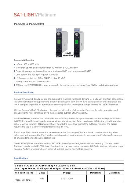
<strong>PL7220T</strong> & <strong>PL7220R10</strong><br />
Features & Benefits<br />
L-Band: 950 – 3000 MHz<br />
More than 25 Km. distance [more than 40 Km with a <strong>PL7220T</strong>1550]<br />
Powerful management capabilites via a front panel LCD and rack mounted SNMP<br />
User control and setting of required IMD level<br />
LNB power control via LCD or SNMP: +13 or 18 VDC<br />
Variety of RF and optical connectors<br />
1550nm and CWDM ITU Grid laser versions for longer fiber runs and single fiber CWDM multiplexing solutions<br />
Product Description<br />
Foxcom’s Platinum L-band products are designed to meet the increasing demand for modularity and high-performance<br />
in a small form factor for superior long-distance transmission. With low RF input power and wide dynamic range, the<br />
link is designed to provide full specification service up to a full 10 dB optical budget with the <strong>PL7220R10</strong> receiver.<br />
Utilizing Foxcom’s DigiRF technology, the user has full control of all important functions for setup, operation, and<br />
analysis via the front panel LCD or via the associated subrack SNMP capability.<br />
In addition IMizer, an automated adjustable link calibration embedded system enables the user to align the RF links<br />
IMD/CNR to specific linearity performances without a two-tone test. Select the desired IMD for the optical transmitter,<br />
either locally or remotely, IMizer automatically adjusts the laser drive to meet the IMD requirements. The IMizer<br />
requires the use of a correction factor table above 2.5 GHz.<br />
Each low profile individual transmitter or receiver can be “hot swapped” in the subrack chassis maintaining a best<br />
subsystem uptime capability. Each module contains an individual processor to maximize specification performance at<br />
all times under demanding user applications.<br />
The <strong>PL7220T</strong> [1550] transmitter and the <strong>PL7220R10</strong> receiver are designed for chassis mounting. The associated<br />
Platinum chassis, model PL7010, has 12 active slots, one main control processor (MCP) slot and two redundant power<br />
supplies. No fans are required even under full subrack loading and full LNB powering.<br />
Specifications<br />
L-Band <strong>PL7220T</strong> [<strong>PL7220T</strong>1550] / <strong>PL7220R10</strong> Link<br />
Low Input Power, 10 dB optical budget [25Km - 1310nm or 40Km - 1550nm]<br />
RF Specifications Units Typical Minimum Maximum<br />
Frequency Range -<br />
MHz 950 - 3000 -
L-Band <strong>PL7220T</strong> [<strong>PL7220T</strong>1550] / <strong>PL7220R10</strong> Link<br />
Low Input Power, 10 dB optical budget [25Km - 1310nm or 40Km - 1550nm]<br />
Bandwidth<br />
Amplitude Response<br />
@ unity gain<br />
950-3000 [MHz]<br />
any 36 MHz<br />
dB<br />
±1<br />
±0.2<br />
±2.25<br />
0.25<br />
Gain Stability dB/24hr ± 0.2 ± 0.25<br />
Gain Slope 1 dB 0 -1.5 +1.5<br />
Gain Variation over<br />
temperature<br />
SFDR 2<br />
SFDR 3<br />
DR (Dynamic Range<br />
- single channel) 4<br />
dB ± 1.5 -2 2<br />
dB/Hz 2/3 88<br />
dB/Hz 2/3 88<br />
dB 30<br />
CNR[any 36 MHz] 2 dB 53 50 57<br />
Noise Figure (NF) 2 dB 38 41<br />
Noise Figure (NF) 3 dB 10 13<br />
Output IP3 (OIP3) 5 dBm 0 -5<br />
Group Delay<br />
Variation - linear<br />
950-1200 MHz<br />
1200-3000 MHz<br />
Input/Output<br />
Impedance<br />
1 dB Compression<br />
Point 2<br />
ns<br />
3<br />
1.5<br />
Ohm 50 or 75<br />
dBm -16 -15<br />
Phase Noise 6 dB None<br />
Third Order<br />
InterModulation<br />
[IMD] 4<br />
RF Input Signal<br />
Range - Total Power<br />
Maximum input<br />
without damage<br />
Output Signal Range<br />
- Total Power 7<br />
8<br />
9<br />
TX/RX Input/Output<br />
Return Loss<br />
50 Ohm<br />
75 Ohm 10<br />
Test Port [front<br />
panel sample port] 11<br />
RF Connector<br />
Input/Output<br />
dBc -40 -55 -40<br />
dBm -50 -25<br />
dBm +15<br />
dBm<br />
dB<br />
-15<br />
-13<br />
-30<br />
-45<br />
-15<br />
-25<br />
-25<br />
dB -20 -22 -18<br />
Type<br />
F, SMA, N
L-Band <strong>PL7220T</strong> [<strong>PL7220T</strong>1550] / <strong>PL7220R10</strong> Link<br />
Low Input Power, 10 dB optical budget [25Km - 1310nm or 40Km - 1550nm]<br />
Test port F, BNC<br />
Optical<br />
Specifications<br />
Typical<br />
Optical Wavelength nm 1310/1550/CWDM<br />
Optical Power Output mW/dBm 2 / 3 1.7/2.5<br />
Optical Budget /<br />
Distance<br />
10 dB optical budget<br />
RX Optical Input<br />
Power<br />
Optical Connector<br />
Types<br />
Km<br />
dBm<br />
1310 nm | 1550 nm<br />
25 |40<br />
-7<br />
FC/APC or SC/APC<br />
(E2000 option)<br />
Optical Return Loss dB -60 -55<br />
Electrical<br />
Specifications<br />
Supply Voltage VDC 12<br />
Supply Current 12<br />
TX, no LNB<br />
Supply Current [TX<br />
with LNB] 6<br />
Amps<br />
0.45<br />
0.75<br />
Amps 0.9 max.<br />
Supply Current (RX) Amps 0.45<br />
EMI Rating<br />
Physical<br />
Specifications<br />
Operating<br />
Temperature Range<br />
Storage<br />
Temperature Range<br />
EMI Rating: FCC Class A,<br />
CE Mark<br />
ºC -10 +55<br />
ºC -45 +85<br />
Relative Humidity 95% non-condensing<br />
Altitude ft / km<br />
Dimensions<br />
[D×W×H]<br />
10,000 [3.08 ] operating 13<br />
14,000 [12.2] non-operating<br />
ins/cm 12×0.8×4 / 30.5×2×10.2<br />
Weight lbs./Kg 0.5 / 0.23<br />
MTBF Hours<br />
TX: 309, 481<br />
RX: 359, 057<br />
MTTR Hours 0.083<br />
Shock & Vibration<br />
Designed for normal transportation environment per section MIL-STD-<br />
810E. Designed to withstand 20G at 11 ms [½ sine pulse] in nonoperating<br />
configuration<br />
-8<br />
-<br />
+1<br />
0.9
1. Within flatness spec<br />
2. -25 dBm RF input, link gain = 0 dB, IMD=-40 dBc @ 0 dBm optical input - max. RF input<br />
3. -55 dBm RF input, link gain =0 dB, IMD=-40 dBc @ 0 dBm optical input - min. RF input<br />
4.<br />
User adjustable<br />
5.<br />
-25 dBm RF in @ IMD=-40 dBc<br />
6.<br />
Direct modulation utilized<br />
7.<br />
Alarm trip point: RED -2 dBm, AMBER -58 dBm<br />
8.<br />
@ 0 dB optical loss<br />
9.<br />
@ 10 dB optical loss<br />
10.<br />
-15 dB @ 950 to 3000 MHz, -11 dB @ 2500 to 3000 MHz<br />
11.<br />
-45 dBm minimum input<br />
12.<br />
Under 10º add 120 mA [laser heating]<br />
13..<br />
WIth standard adiabatic derating at 2ºC/1000ft. [0.3 Km.]<br />
All specifications are subject to change without notice.<br />
Ordering Information