Wiener Lautsprecher Manufaktur (WLM)
Wiener Lautsprecher Manufaktur (WLM)
Wiener Lautsprecher Manufaktur (WLM)

You also want an ePaper? Increase the reach of your titles
YUMPU automatically turns print PDFs into web optimized ePapers that Google loves.
1. Thanks!<br />
Active Filter Module: SYSTEM CONTROL<br />
Manual<br />
We thank you for having chosen the active filter module SYSTEM CONTROL (SC) and<br />
the confidence you have thus proven in our product.<br />
Due to the new functioning of the <strong>WLM</strong> speakers and their electronic modules we are<br />
asking you to read this manual carefully before connecting or operating this SC module<br />
within your chain. Your benefits: an optimized installation will lead to an improved sound<br />
reproduction<br />
2. Supply<br />
The supply of the SYSTEM CONTROL comprises:<br />
• 1 Power cord (Mains to SC)<br />
• 1 SYSTEM CONTROL module<br />
• 1 Remote Control (optional)<br />
• 1 Power cord (SC to another unit)<br />
• This manual<br />
• Warranty Registration<br />
The packaging of the SC provides a perfect protection to our product during<br />
transportation. We recommend to keep it for future shipping needs.<br />
3. Safety Notice<br />
All elements for the operation and the functioning of the SC are accessible from<br />
outside. There are no fuses inside of the module to be replaced.<br />
You run the risk to loose your warranty when you open the SC.<br />
Before starting to connect the SC with the different units of your chain, make sure<br />
the SC is switched off (keep in mind the special relay delayed shut off).<br />
MANUAL <strong>WLM</strong> SYSTEM CONTROL 1/12
4. Installation<br />
To the extent possible, please place the SC away from the amplifiers and other units of<br />
your chain having a transformer.<br />
Even though the SC itself is emitting little heat, it should nevertheless not be placed to<br />
close to other units. Make sure there is enough space for ample ventilation along all<br />
sides of the SC.<br />
Please protect the SC from heat, moisture and mechanical damage (drops, hits etc.)<br />
5. Description<br />
Power Supply HIGH, MID Frequency Module BASS Module<br />
The front panel contains the control lights (LEDs), all the elements for the operation and<br />
the receiver unit for the remote control (optional) signal; at the rear panel you will find the<br />
RCA input connectors for the input signal (coming from the pre-amp) and the RCA output<br />
connectors for the signal going to the amps, as well as the switch to activate the remote<br />
control operation of the SC and a power plug-in module (for the mains connection of the<br />
SC and for the power connection of other units via the SC)<br />
5.1 Power Supply Module<br />
5.1.1 Start Up<br />
The SC will be started manually by the front switch: Power “ON“<br />
The power supply to the integrated modules (high, medium, low frequencies) is indicated<br />
by the 2 green LEDs (15V+, 15V-).<br />
The SC offers a power link (including ON/OFF switching of this link) to another unit (e.g.<br />
amp or the entire chain, max. load is 4000 W). Thus, the SC and the connected unit(s)<br />
can be started and stopped even via the remote control.<br />
MANUAL <strong>WLM</strong> SYSTEM CONTROL 2/12
The following 4 fuses are located at the rear of the SC:<br />
• 2 x 500mA LowBlow for the operation of the integrated SC modules (high,<br />
medium, low frequencies)<br />
• 1 x 100mA LowBlow for the internal primary power supply<br />
• 1 x 10A LowBlow internal relay for the external units.<br />
5.1.2 Switch OFF<br />
The operation power "OFF" will cut off the power supply, however delayed by 30<br />
seconds. This feature offers a distinct advantage particularly for tube amps which keep<br />
sending the signal during a certain time after cut-off. The delayed cut-off will avoid loud<br />
and disturbing switching noises.<br />
5.1.3 ON/OFF switching by the remote control<br />
To use the ON/OFF switching feature of the remote control, the main switch (front panel)<br />
and the remote switch (rear panel) have to be in ON position. The OFF command from<br />
the remote control will put the SC in STAND BY mode, shown by the red LED.<br />
In case of remote control failure (e.g. low batteries) SC and linked units can be switched<br />
ON and OFF by the main switch, provided the REMOTE CONTROL feature has been<br />
shut off by the REMOTE CONTROL switch at the rear panel. To use the REMOTE<br />
CONTROL again, the rear switch must be in ON position.<br />
We recommend the complete shut off of the SC when it is not used for a longer period.<br />
5.2 High-/Medium Frequency Modules<br />
Via the upper buttons at the front panel the volume of the high and medium frequencies<br />
can be adjusted separately.<br />
Below the volume turn knobs you will find the knobs to modify the acoustic parameters of<br />
the high, medium and low frequencies; they enable you to adjust the sound reproduction<br />
to the acoustics of the listening environment and also to your individual preference.<br />
HARMONIC WAVE: offers the adjustment of the upper wave range (high frequencies);<br />
the sound of the upper frequencies can be adjusted for more precision when the emitted<br />
waves are excessively worn and/or absorbed by the room acoustics. Also, by this means<br />
you can counteract the tendency of various tube amps to switch the phase of the upper<br />
frequencies.<br />
BASS LINE: with this adjustment the main sound parameters between 80 and 150 Hz<br />
can be adjusted. Since the influence of the room acoustics to this frequency range is<br />
particularly crucial, you have the possibility to adjust the dominant main sound waves via<br />
BASS LINE and LEVEL control to the prevailing room acoustics. You will find that the<br />
average frequency adjustment is placed at between the positions 3 and 6 on the BASS<br />
LINE scale; an adjustment above this value will produce a fuller main signal (e.g. voices<br />
and instruments).<br />
MANUAL <strong>WLM</strong> SYSTEM CONTROL 3/12
Examples of the adjustment:<br />
• LEVEL: +3dB, BASS LINE: 2 to 3 Voices will be slimmer and more present<br />
• LEVEL: 0dB, BASS LINE: 6 to 12 Voices are fuller, instruments are reproduced<br />
more dynamically and with more pressure<br />
5.3 Bass-Modul<br />
Connection-Schematics<br />
DUO<br />
R L<br />
Output R Output L<br />
Power Amp. Stereo Mode<br />
Input R Input L<br />
MANUAL <strong>WLM</strong> SYSTEM CONTROL 4/12
Similar to the previous description of the control knobs, the same kind of adjustments are<br />
possible at the low frequency module: the volume of the low frequency signal with the<br />
upper knob, the acoustic parameters with the knob below.<br />
With the LOW BASS adjustment you can choose the parameters best suited for the<br />
coupling of the sub woofer to the main speaker; at the same time you can rectify the low<br />
frequency signal and change the phase situation. The average position is between 4 to 8<br />
at the scale and may be changed higher or lower, to your liking. A higher value will lower<br />
the frequency cut-off between main speaker and sub.<br />
Examples of adjustment:<br />
• LEVEL: +3dB, LOW BASS: 1 to 4: the bass will become faster and firmer<br />
• LEVEL: 0dB, LOW BASS: 8 to 12: the bass is fuller and softer/rounder<br />
(obviously always in relation to the prevailing room acoustics)<br />
5.4 Connections at the rear of the SC<br />
At the rear panel of the SC you will find the separate RCA outputs for the connection with<br />
the corresponding amps at each of the corresponding modules (high, medium and low<br />
frequency).<br />
Because of their location and their description, these connections can not really be<br />
mistaken; however this part of the set-up should be done carefully. An awful sound<br />
reproduction may be the result otherwise.<br />
The pair of RCA connectors for the signal input to the SC (coming from the pre-amp) is<br />
located below the output connectors, clearly marked and not to be mistaken.<br />
Illustration of the connection<br />
Amp<br />
Bass<br />
Amp<br />
MID<br />
CD<br />
SACD<br />
Amp<br />
HIGH<br />
Pre-<br />
Amp<br />
AC - Connection<br />
AC Wall<br />
MANUAL <strong>WLM</strong> SYSTEM CONTROL 5/12
Make sure that the pre-amp, the SC and the amps are in "OFF" position before<br />
starting the connection set up!<br />
5.5 Ground connection of the power supply<br />
Pre-amp and amps should have their mains connection without grounding; otherwise an<br />
additional ground loop will be created (in addition to the earth connection via the<br />
connecting cables). Two overlapping loops would cause the risk of unpleasant hum. The<br />
suppression of the grounding of the other units within your chain can be achieved easily<br />
by connecting them to the mains supply of the SC (there the grounding will be<br />
automatically disconnected). Your chain's power connection will nevertheless be<br />
executed according to the prevailing safety rules.<br />
6 Operation and functioning<br />
At the beginning you may be "disturbed" by the number of lights, knobs and switches on<br />
the SC. Therefore, at the beginning a few general remarks to the functioning of the SC.<br />
When trying to determine your individual setting of the high, medium and low frequencies<br />
think of the turn knobs in the upper row of the 3 modules as volume knobs, based on and<br />
in addition to the volume knob of your pre-amp.<br />
The 3 volume knobs of the SC enable you to set the volume proportion of a given signal<br />
separately for the high, medium and low frequencies.<br />
A bad setting will not damage the SC or the connected units (amps or speakers).<br />
However to protect the speaker membrane always start with a setting with lower values,<br />
which you may rise subsequently.<br />
We are actually inviting you to play freely with the various volume combinations. Get your<br />
ears used to the effect of the various volume levels and their changes. E.g. start reducing<br />
the volume of just one of the frequency ranges, keep the others as they are. And after a<br />
while reverse the same adjustment again until you will reach an acceptable level. Do the<br />
same with the other frequency ranges. In doing so you will familiarize yourself with the<br />
effect of the various adjustments.<br />
With the lower turn knobs you can change the sound characteristics separately of the<br />
high, medium and low frequencies. The chosen levels will have a direct and immediate<br />
effect of the sound reproduced in relation to a given listening environment. At the<br />
beginning we are recommending to start with the following settings of the pre-amp and<br />
SC:<br />
• Reduce the volume of your pre-amp to "0".<br />
• At the SC, choose a LEVEL (volume) of 0 dB for high, medium and low frequencies;<br />
• Keep the Harmonic Wave at the high frequency module to "0" ;<br />
• Put the knobs for Bass-Line and Low Bass (of the modules "MID" and "Bass") to "3".<br />
• Now start your source (e.g. CD or LP) and increase the volume via the turn knob of<br />
your pre-amp up to the desired level.<br />
MANUAL <strong>WLM</strong> SYSTEM CONTROL 6/12
Thereafter you may "experiment" with the high, medium and low portions of the signal to<br />
find the best suitable sound for your room. You may want to adjust this first setting when<br />
listening to another recording, and thereafter again. For this purpose we highly<br />
recommend the comfortable use of the (optional) remote control.<br />
Soon you will find out how the sound will change when changing the different parameters<br />
plus level proportions of the high, medium and low frequencies of a given signal.<br />
7 General hints for the choice of the amp<br />
It is up to your personal preference and budgetary limits which amp you will employ.<br />
The amps can work with transistors or tubes, or both. However not mixed within one<br />
frequency range (high or medium frequencies). For the SUB you should always use<br />
transistor amps, because of their higher damping factor. Even though only 1 pair of<br />
speaker cables (1 channel) is to be fed to the SUB, always use a stereo amp: connect<br />
the right input connector of the sub to the plus (+) output of the right channel of the amp<br />
and accordingly the left input of the SUB to the plus (+) output of the left channel of the<br />
amp.<br />
Keep in mind that a "poor" amp will lower the level of performance of the entire chain,<br />
even though the other amps may be of exceptional quality.<br />
High demands are to be placed on the connecting cables. They should all be of similar<br />
quality and performance characteristics. The same applies to the speaker cables.<br />
8 Technical explanations<br />
8.1 Speaker Efficiency<br />
The efficiency of a speaker system, measured in sound pressure (dB at 1W, at a<br />
distance of 1 m), specifies its effectiveness of reproducing a given signal. The higher the<br />
efficiency, the lower the demand regarding the performance of an amplifier and the<br />
efforts required to reach higher volume levels.<br />
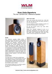
<strong>WLM</strong> speakers excel in this respect, since they offer an exceptional and unusual<br />
efficiency of 98 dB (1W, 1m).<br />
8.2 Impulse Behavior<br />
The faster and the more precise a speaker responds to the changes of a signal impulse<br />
(by swinging the membrane forward and backward), the better the sound impression will<br />
be. The smallest delays between the reception of the impulse and its transformation<br />
(initiation of the membrane movement and its stop) will have a distinct impact on the<br />
quality of the sound reproduced and perceived.<br />
The specially hard support of the paper membranes on one side and the extremely<br />
strong, high performance magnet coils on the other side are warrants for an extraordinary<br />
impulse behavior of all <strong>WLM</strong> speaker systems.<br />
MANUAL <strong>WLM</strong> SYSTEM CONTROL 7/12
8.3 PAC ("Phase Acoustic Corrected")<br />
PAC stands for a special and unique advantage of the <strong>WLM</strong> speakers; i.e. the capability<br />
of reproducing an almost perfect sound stage in 3-dimensional extension with 2<br />
speakers.<br />
To understand this concept we have to explain that lower frequencies alone do not lend<br />
themselves and are therefore not vital for the stage building process during the sound<br />
reproduction. Only with higher frequencies stage building (and perception) is possible.<br />
Therefore, to reproduce a given signal in a space-like manner it is important that it<br />
contains medium and high frequencies together with the lower frequency waves.<br />
The prevailing sounds in our surrounding world, usually deriving from single sources,<br />
consist of a mix of different frequencies and are discerned and located readily in a given<br />
space context. On the other hand, our ears have to accomplish the difficult task to<br />
amalgamate the sounds reproduced "artificially" by 2 separate loudspeakers via special<br />
drivers for high and medium/low frequencies to a full space-like entity.<br />
Speakers having conventional tweeter concepts in a variety of techniques are fighting<br />
with the difficulty to fuse the higher and lower frequencies deriving from the 2 stereo<br />
speakers for space-like perception. The high frequency waves conventionally emitted in<br />
front direction do not merge with the medium and low frequency waves coming from the<br />
same speaker and also not with the high frequencies portions coming from the tweeter of<br />
the other (stereo) speaker. The listener's ear can not be betrayed, he will hear the<br />
speakers rather than the music in its appropriate spacious extension. In addition, the<br />
higher frequencies are traveling so much faster to our ears than the medium or lower<br />
signal portions. This will result in disturbing time lags over the entire frequency range,<br />
overemphasizing the distinct 2-channel reflection of sound, also destroying any chance of<br />
a natural, space-like perception of the music reproduced.<br />
The special execution and positioning of the tweeter system of the <strong>WLM</strong> speakers is<br />
enabling first the homogenous merging of the high frequencies emerging from the 2<br />
juxtaposed speakers and then also the merging with the medium and low frequencies of<br />
a given signal coming from different drivers. The <strong>WLM</strong> listener is able to hear a distinctly<br />
structured sound stage image. No longer is he limited and fixed to a narrowing 2-channel<br />
reproduction of his speakers. In the listener's acoustic perception the <strong>WLM</strong>-PAC<br />
speakers will actually disappear in the background. He will experience the rare and<br />
rewarding feeling of being put right in the middle of the recording atmosphere.<br />
The world unique PAC technology is granting for the first time an almost perfect spacelike<br />
imaging of recorded music from 2 loudspeakers only.<br />
MANUAL <strong>WLM</strong> SYSTEM CONTROL 8/12
9 Technical Data<br />
Active Three Way Filtering Module with stabilized Power Supply<br />
Filter of second to fourth degree (<strong>WLM</strong>-own variable cut-off function)<br />
Double - Mono concept<br />
THD 0,001% at 20 to 20 kHz<br />
Adjustment Range of the Cut-Off Frequencies<br />
Bass from 60 to 100Hz adjustable<br />
Medium frequency levels up to about 1000Hz<br />
High frequency levels from about 1000Hz upward<br />
Internal Power Supply +15V/-15V<br />
Power consumption max. 15 Watt<br />
Max. loading of mains output: 4000W<br />
Internal fuses<br />
• 2 x 500mA LowBlow for the operation of the integrated SC modules (high,<br />
medium, low frequencies)<br />
• 1 x 100mA LowBlow for the internal primary power supply<br />
• 1 x 10A LowBlow internal relay for the external units<br />
MANUAL <strong>WLM</strong> SYSTEM CONTROL 9/12
Remote Control of <strong>WLM</strong> SYSTEM CONTROL<br />
(as option)<br />
on<br />
off<br />
+<br />
-<br />
High<br />
Range<br />
Bass<br />
• On…To switch on the <strong>WLM</strong> SYSTEM CONTROL 3, 5, 6.<br />
(And further units connected to the SYSTEM CONTROL via the main relay)<br />
• Off…to shut off the <strong>WLM</strong> System Control 3, 5, 6 (delayed).<br />
• High Range +<br />
To increase the high frequencies<br />
• High Range -<br />
To lower the high frequencies<br />
• Bass Range +<br />
To increase the low frequencies<br />
• Bass Range -<br />
To lower the low frequencies<br />
MANUAL <strong>WLM</strong> SYSTEM CONTROL 10/12
10. Warranty<br />
Limited Warranty<br />
During the warranty period the <strong>Wiener</strong> <strong>Lautsprecher</strong> <strong>Manufaktur</strong> will guarantee that their<br />
products are free of flaws and well functioning<br />
The warranty period for the SYSTEM CONTROL is 2 years (counted from the date of<br />
purchase at an authorized <strong>WLM</strong>-Dealer).<br />
Condition for the warranty service is that the products are operated in accordance with<br />
this manual.<br />
During the warranty period <strong>WLM</strong> will replace or repair the defect parts free of charge to<br />
the customer.<br />
Condition is however:<br />
• The warranty registration card is received by <strong>WLM</strong> within 30 days after the date of<br />
purchase.<br />
• The cabinets are not showing any traces of physical damage and inside there are<br />
no signs of overheating due to wrong installation/operation resulting in an<br />
overloading of certain parts.<br />
• The PCBs and components thereof are not showing any signs of undue handling,<br />
regardless whether the intention was to repair or to modify the unit under claim<br />
• There is no indication what-so-ever that the <strong>WLM</strong> products have been operated<br />
differently as specified by the manual..<br />
In addition, the customer will loose his right for a warranty claim when the serial-Nr. of the<br />
unit in question has been modified, removed or manipulated in any way. <strong>WLM</strong> will not be<br />
held responsible for damages resulting from repairs executed by un-authorized<br />
personnel.<br />
Collateral Damage<br />
During the duration of this limited warranty period (and there-after) <strong>WLM</strong> will not be<br />
responsible for collateral damage, directly or indirectly linked to the operation of the <strong>WLM</strong><br />
product.<br />
Warranty claim<br />
The customer may on the basis of this limited warranty claim the repair or replacement of<br />
the defective part by the manufacturer or the authorized dealer with no charge to him. For<br />
the claim please contact either <strong>WLM</strong> directly or the <strong>WLM</strong> distributor in your country. After<br />
receipt of the claim confirmation please send the unit under claim to the shown address.<br />
The defect will be examined and, when justified, will be repaired at no cost to the<br />
customer. The customer will have to bear the cost of shipment. Without a corresponding<br />
warranty claim (received within 30 days after the date of purchase at the address below)<br />
no warranty claim will be accepted or processed.<br />
<strong>WLM</strong> Loudspeakers<br />
Treietstrasse 56<br />
6832 Sulz<br />
AUSTRIA<br />
Phone: +43 (0)5522 44641 (Customer Service)<br />
Web: www.wlm-loudspeakers.com<br />
MANUAL <strong>WLM</strong> SYSTEM CONTROL 11/12
<strong>WLM</strong> Warranty Registration<br />
Please ask your dealer to fill in this form at the time of the purchase.<br />
This registration will entitle you to call on <strong>WLM</strong> for technical support and it is<br />
a prerequisite for an eventual warranty claim against <strong>WLM</strong>.<br />
Please send your<br />
registration to:<br />
<strong>WLM</strong> Loudspeakers<br />
Treietstrasse 56<br />
A-6832 Sulz<br />
Austria<br />
Customer Service:<br />
Phone : +43 (0)5522 44641<br />
Fax : +43 (0)5522 44641-74<br />
Web : www.wlm-loudspeakers.com<br />
Unit/Model: SYSTEM CONTROL..…Serial-Nr.:.........................................................<br />
Date of Purchase:.............................Dealer Name:....................................................<br />
Dealer Address:..........................................................................................................<br />
First/last name of customer: ...................................................................................<br />
Address Street: ...................................................................................<br />
Postal Code/Town: ...….............................................................................<br />
Customer Contact Phone: ...................................................................................<br />
Your comments are always appreciated:<br />
Fax: ...................................................................................<br />
E-Mail: ...................................................................................<br />
MANUAL <strong>WLM</strong> SYSTEM CONTROL 12/12