Basic Concepts of Ventilation Design - GHDonline
Basic Concepts of Ventilation Design - GHDonline
Basic Concepts of Ventilation Design - GHDonline

You also want an ePaper? Increase the reach of your titles
YUMPU automatically turns print PDFs into web optimized ePapers that Google loves.
Building <strong>Design</strong> and Engineering<br />
Approaches to Airborne Infection Control<br />
<strong>Basic</strong> <strong>Concepts</strong> <strong>of</strong><br />
<strong>Ventilation</strong> <strong>Design</strong><br />
Jack Price
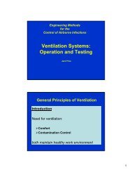
General Principles <strong>of</strong> <strong>Ventilation</strong><br />
Introduction<br />
Need for ventilation:<br />
�Comfort<br />
�Contamination Control<br />
both maintain healthy work environment
General Principles <strong>of</strong> <strong>Ventilation</strong><br />
• Office buildings ----- In-door air quality<br />
• Occupational exposure ---- OSHA<br />
• Environmental releases ---- EPA
General Principles <strong>of</strong> <strong>Ventilation</strong><br />
• Regulatory Agencies (compliance concerns)<br />
• Federal<br />
• State<br />
• Local<br />
• Good Practice<br />
• Standard <strong>of</strong> care (industry standards ANSI, ASME, etc.)<br />
• Work productivity<br />
• Process control
• Supply<br />
• Exhaust<br />
Types <strong>of</strong> Systems<br />
Temperature & Humidity<br />
Replacement (make-up air)<br />
Return (recirculated air)<br />
General (dilution)<br />
Local Control (hoods)
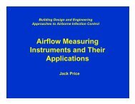
Air Handling System with Economizer<br />
HVAC Systems<br />
Air Balance in a Conditioned Space
• Temperature<br />
• Pressure<br />
• Air Contaminants<br />
• Work Practices<br />
• Product Protection<br />
• Worker Protection<br />
• Building Codes<br />
<strong>Design</strong> Concerns<br />
• Equipment Selection<br />
• Energy Conservation<br />
• Maintenance<br />
• Security<br />
• Expansion
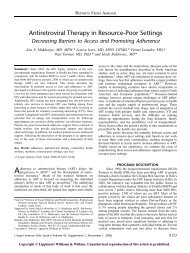
Patient Isolation Room with HEPA Exhaust Filtration
Air Conditioning System Water and Refrigeration Circuits
Factors in the Perception <strong>of</strong> Air Quality
Conversion Factors<br />
Quantity To Convert Into Multiply By:<br />
Volumetric<br />
Flow<br />
cubic feet/minute<br />
(ft3 /min)<br />
Velocity feet/minute<br />
(fpm)<br />
Pressure inches water<br />
(in w.g.)<br />
cubic meters/second<br />
(m3 /sec)<br />
meters/second<br />
(m/s)<br />
Pascals<br />
(Pa)<br />
4.719 x 10 -4<br />
0.00508<br />
249.1
Q = V . A<br />
Conservation <strong>of</strong> Mass<br />
1 velocity = 50 FPM<br />
Hood<br />
2 velocity = 3000 fpm<br />
Duct<br />
Flow rate at point 1 is called Q 1<br />
and is equal to<br />
flow rate at point 2 which is called Q 2<br />
Where Q = Volumetric Flow Rate, ft3 /min<br />
V = Air Velocity, ft/min or fpm<br />
A = Cross Sectional Area, ft2 or SF<br />
Air Flow
Q = V . A<br />
Conservation <strong>of</strong> Mass<br />
8 inch duct<br />
1<br />
6 inch duct<br />
2<br />
12 inch duct<br />
3<br />
Q 1 + Q 2 = Q 3<br />
V 1 A 1 + V 2 A 2 = V 3 A 3
AIR FLOW<br />
• At standard temperature and pressure (STP):<br />
* 1 atmosphere & 70 o F *<br />
The density <strong>of</strong> air is 0.075 lb m /ft 3<br />
• Air will flow from a higher pressure region to a<br />
lower pressure region<br />
• Three Different Types <strong>of</strong> Pressure Measurements<br />
* Static * Velocity * Total *
Types <strong>of</strong> Pressure Measurements<br />
• Static Pressure (S P)<br />
potential energy bursting or collapsing<br />
can be + or – measured perpendicular to flow<br />
• Velocity Pressure (V P)<br />
kinetic energy accelerates from 0 to some velocity<br />
Exerted in direction <strong>of</strong> flow always +<br />
• Total Pressure (T P)<br />
combined static & velocity components measure <strong>of</strong> energy content <strong>of</strong> air stream<br />
can be + or - Always decreasing as flow travels<br />
downstream thru a system only rising when<br />
going across a fan
TP = SP + VP<br />
TP<br />
SP<br />
_<br />
+<br />
_<br />
+<br />
VP +
Conservation <strong>of</strong> Energy<br />
• TP = SP + VP or T P = S P + V P<br />
• Energy losses:<br />
– Acceleration <strong>of</strong> air<br />
– Hood entry<br />
– Duct losses: friction (function <strong>of</strong> system materials & design)<br />
– Fitting losses: contractions & expansions<br />
• T P1 = T P2 + h L<br />
• S P1 + V P1 = S P2 + V P2 + h L<br />
now substitute T P = S P + V P
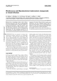
Hood<br />
Bench Grinder<br />
Pressure Graphs for TP, SP, and VP
Velocity Pressure & Velocity<br />
• V = 1096 (V P/p) 0.5<br />
• V = 4005 (V P ) 0.5<br />
where p = air density<br />
@ STP p = 0.075 lb m/ft 3<br />
• Velocity pressure is a function <strong>of</strong> the velocity and<br />
fluid density.<br />
• Velocity pressure will only be exerted in the direction<br />
<strong>of</strong> air flow and is always positive.
1<br />
Bench Grinder Exhaust <strong>Ventilation</strong><br />
• Q 1 = Q 2<br />
• If Q desired is 300 cfm<br />
• Then Q = V A<br />
V = Q A<br />
V = (300) / (0.0068)<br />
V = 4490 fpm<br />
Duct diameter = 3 inches<br />
Area = 0.0668 ft 2<br />
2 3<br />
• If there are no losses from the<br />
grinder hood entry then:<br />
SP 1 + VP 1 = SP 2 + VP 2<br />
but: SP 1 = 0 and VP 1<br />
we then have:<br />
0 = SP 2 + VP 2<br />
or -VP 2 = SP 2<br />
0
1<br />
Bench Grinder Exhaust <strong>Ventilation</strong><br />
• If there are no losses from the<br />
grinder hood entry then:<br />
SP 1 + VP 1 = SP 2 + VP 2<br />
but: SP 1 = 0 and VP 1<br />
we then have:<br />
0 = SP 2 + VP 2<br />
or SP 2 = (-VP 2 )<br />
0<br />
Duct diameter = 3 inches<br />
Area = 0.0668 ft 2<br />
2 3<br />
V = 4490 fpm<br />
• from V = 4005 (VP) 0.5<br />
• VP 2 = (4490/4005) 2<br />
• VP 2 = 1.26 in w.g.<br />
• then: SP 2 = (-VP 2 )<br />
SP 2 = -1.26 in w.g.
1<br />
Bench Grinder Exhaust <strong>Ventilation</strong><br />
SP h<br />
Duct diameter = 3 inches<br />
Area = 0.0668 ft 2<br />
2 3<br />
• However there are losses thru the grinder hood entry<br />
SP 2 = - (VP 2 + h e ) where h e is the energy loss <strong>of</strong> the hood entry<br />
• Static pressure (SP) must decrease due to acceleration <strong>of</strong> air up to the duct velocity<br />
• F h is defined as the energy loss factor (for that hood design)<br />
• Energy losses will be measured as a function <strong>of</strong> the velocity pressure in the system<br />
h e = (F h ) (VP)<br />
• Now we define the static pressure at the hood as SP h<br />
V = 4490 fpm<br />
• SP h is also called the hood static suction and is the absolute value <strong>of</strong> SP 2
1<br />
Bench Grinder Exhaust <strong>Ventilation</strong><br />
S Ph<br />
• Now add the hood entry loss:<br />
Duct diameter = 3 inches<br />
Area = 0.0668 ft 2<br />
2 3<br />
SP h = VP 2 + h e = VP 2 + (F h ) (VP 2 )<br />
Assume that the hood energy loss factor for this hood is 0.40<br />
V = 4490 fpm<br />
• SP h = 1.26 + (0.40) (1.26) = 1.76 in w.g.
Flanged Inlet with Fd = 0.49
Flanged Inlet with F d = 0.49
Hood Entry Coefficients<br />
Actual Flow<br />
C e = Hypothetical Flow no losses<br />
(4005) (VP) 0.5 (A) (VP) 0.5<br />
C e = =<br />
(4005) (SP h ) 0.5 (A) (SP h ) 0.5<br />
C e = (VP/SP h) 0.5
Hood Entry Coefficients<br />
C e = (VP/SP h ) 0.5<br />
Typical values for C e are known for some hoods.<br />
For the bench grinder hood with a straight take-<strong>of</strong>f :<br />
Ce = 0.78
Example Problem<br />
• What static pressure (SP h) should be set<br />
at the bench grinder hood to maintain a<br />
duct velocity <strong>of</strong> 4000 fpm if the take-<strong>of</strong>f<br />
duct size is 4 inch diameter ?<br />
• What is the volumetric flow rate ?
Example Problem<br />
• V = 4000 fpm Q = VA = 4005(A)(VP) 0.5 Q = VA = 348 cfm<br />
• A for 4 inch duct diameter = 0.087 ft2 • C e bench grinder hood = 0.78<br />
C e = (VP/SP h ) 0.5 = 0.78<br />
(VP/SP h ) = (0.78) 2<br />
SP h = VP/(0.78) 2 = (0.998)/(0.608) = 1.64 in w.g.<br />
V = 4005 (VP) 0.5<br />
(VP) 0.5 = (4000)/(4005)<br />
VP = 0.998 in w.g.<br />
1.64 in w.g.
Air Flow Characteristics<br />
• See Industrial <strong>Ventilation</strong> Manual notes<br />
Blowing vs. Exhausting
Air Flow Characteristics<br />
Exhaust Hoods<br />
Capture Velocity<br />
From Dalla Valle’s<br />
empirical work<br />
V (x) = Q/ (10 x 2 + A)
Capture Velocity<br />
V (x) = Q/ (10 X 2 + A)<br />
Capture velocity is<br />
only effective in the<br />
immediate vicinity<br />
<strong>of</strong> the hood<br />
Room supply air (makeup<br />
air) discharge can<br />
influence effectiveness<br />
<strong>of</strong> hood capture
Questions ?
In-Place In Place Filter Testing Workshop<br />
<strong>Ventilation</strong> Systems:<br />
Operation and Testing
HVAC Systems
Air Handling System with Economizer<br />
HVAC Systems<br />
Air Balance in a Conditioned Space
Questions ?