EOe1-A User Manual - Products
EOe1-A User Manual - Products
EOe1-A User Manual - Products

You also want an ePaper? Increase the reach of your titles
YUMPU automatically turns print PDFs into web optimized ePapers that Google loves.
Chapter 2. Installation<br />
2.1 General<br />
13<br />
Chapter 2 Installation<br />
This chapter provides detailed instructions for mechanical installation of the <strong>EOe1</strong>-A. Following the completion of<br />
installation, please refer to Chapter 3 for operating information.<br />
2.2 Site Preparation<br />
Install the <strong>EOe1</strong>-A within reach of an easily accessible grounded AC outlet or DC source. The AC outlet should be<br />
capable of furnishing 90~250VAC. DC power capable units connect via terminal block connection. Allow at least 10<br />
cm (4 inch) clearance at the rear of the <strong>EOe1</strong>-A for signal lines and interface cables.<br />
2.3 Mechanical Assembly<br />
The <strong>EOe1</strong>-A is designed for tabletop or bench installation, and is delivered completely assembled. No provisions are<br />
made for bolting the <strong>EOe1</strong>-A to the tabletop. An optional rack mount kit is available for standard EIA 19" mounting.<br />
2.4 Electrical Installation<br />
Power connection<br />
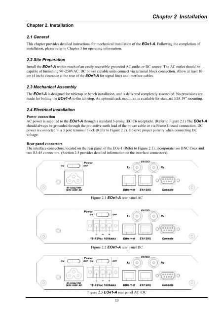
AC power is supplied to the <strong>EOe1</strong>-A through a standard 3-prong IEC C6 receptacle. (Refer to Figure 2.1) The <strong>EOe1</strong>-A<br />
should always be grounded through the protective earth lead of the power cable or via Frame Ground connection. DC<br />
power is connected to a 3 pole terminal block (Refer to Figure 2.2). Observe proper polarity when connecting DC<br />
voltage.<br />
Rear panel connectors<br />
The interface connectors, located on the rear panel of the EOe-1 (Refer to Figure 2.1), incorporate two BNC Coax and<br />
two RJ-45 connectors. (Section 2.5 provides detailed information on the interface connectors).<br />
Figure 2.1 <strong>EOe1</strong>-A rear panel AC<br />
Figure 2.2 <strong>EOe1</strong>-A rear panel DC<br />
Figure 2.3 <strong>EOe1</strong>-A rear panel AC+DC