Ofrecido por www.electromanuales.com - Electromanuals.org
Ofrecido por www.electromanuales.com - Electromanuals.org
Ofrecido por www.electromanuales.com - Electromanuals.org

Create successful ePaper yourself
Turn your PDF publications into a flip-book with our unique Google optimized e-Paper software.
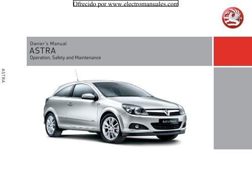
ASTRA<br />
Owner’s Manual<br />
ASTRA<br />
Operation, Safety and Maintenance<br />
<strong>Ofrecido</strong> <strong>por</strong> <strong>www</strong>.<strong>electromanuales</strong>.<strong>com</strong>
<strong>Ofrecido</strong> <strong>por</strong> <strong>www</strong>.<strong>electromanuales</strong>.<strong>com</strong><br />
VAUXHALL Astra<br />
Operation, Safety, Maintenance
Data specific to your vehicle<br />
Please enter your vehicle’s data here to keep it ea sily accessible.<br />
This information is available under the section "Technical da ta " as well as on the identification plate and in the Service Booklet.<br />
Fuel<br />
Engine oil<br />
Tyre pressure<br />
Designation<br />
Grade<br />
Viscosity<br />
Weights<br />
Permissible gross vehicle weight<br />
Tyre size for loa d with 1 person and<br />
lig ht lugga ge<br />
wi th full load<br />
Summer tyres Front Rear Front Rear<br />
Winter tyres Front Rear Front Rear<br />
– EC kerb weight<br />
= Loading<br />
<strong>Ofrecido</strong> <strong>por</strong> <strong>www</strong>.<strong>electromanuales</strong>.<strong>com</strong>
Your Astra<br />
is an intelligent <strong>com</strong> bination of forwardlooking<br />
technology, impressive safety,<br />
environmental friendliness and economy.<br />
It now lies with you to drive your vehicle<br />
safely and ensure that it perform s<br />
perfectly. This Owner’s Manual provides<br />
you with all the necessary information to<br />
that end.<br />
Make sure your pa ssengers are aware<br />
of the possible risk of accident and injury<br />
which may result from improper use of the<br />
vehic le.<br />
You m ust always <strong>com</strong>ply w ith the sp ecific<br />
laws of the country that you are travelling<br />
through. These laws may differ from the<br />
inform ation in this Ow ner’s Manual.<br />
<strong>Ofrecido</strong> <strong>por</strong> <strong>www</strong>.<strong>electromanuales</strong>.<strong>com</strong><br />
When this Manual refers to a workshop<br />
visit, we re<strong>com</strong>mend your Vauxhall<br />
Authorised Repairer.<br />
All Vauxhall Authorised Repairers provide<br />
first class service at reasonable prices.<br />
You will receive quick, reliable and<br />
individua l service.<br />
Experienced mechanics, trained by<br />
Vauxhall, work according to specific<br />
Vauxhall instructions.<br />
The Owner’s Ma nual should alwa ys be kept<br />
in the vehicle: Ready to hand in the glove<br />
<strong>com</strong>partment.<br />
Make use of the Owner’s Manual:<br />
z The "In Brief" section will give you an<br />
initial overview.<br />
z The table of contents at the beginning<br />
of the owner’s manual and within the<br />
individual chapters will show you where<br />
everything is.<br />
z Its index will help you find what you<br />
want.<br />
z It w ill familiarise you with the<br />
sophisticated technology.<br />
z It w ill increase your pleasure in your<br />
vehicle.<br />
z It will help you to handle your vehicle<br />
expertly.<br />
The Owner’s Manual is designed to be<br />
clearly laid out and easily understood.<br />
This sym bol signifies:<br />
6 Continue reading on next page.<br />
3 Items m arked with an asterisk are not<br />
fitted to all vehicles (model variants,<br />
engine options, models specific to one<br />
country, optional equipment, Genuine<br />
Vauxhall Parts and Accessories).<br />
9 Warnin g<br />
Text marked 9 Warning provides<br />
information on risk of accident or injury.<br />
Disregard of the instructions may lead to<br />
injuries or endanger life.<br />
Inform your passengers accordingly.<br />
Yellow arrows in the illustrations serve as<br />
points of reference or indicate some action<br />
to be performed.<br />
Black arrows in the illustrations indicate<br />
a reaction or a second action to be<br />
performed.<br />
Directional data, e.g. left or right, or front<br />
or back, in the descriptions always relate to<br />
the direction of travel.<br />
Thank you for choosing a Vauxhall. We<br />
wish you many hours of pleasurable<br />
driving.<br />
Your Vauxhall Team
Contents<br />
<strong>Ofrecido</strong> <strong>por</strong> <strong>www</strong>.<strong>electromanuales</strong>.<strong>com</strong><br />
Commitment to customer<br />
satisfaction:<br />
Our ai m: to keep you happy with your<br />
vehicle. All Vauxhall Authorised Repairers<br />
offer first-class service at <strong>com</strong>petitive<br />
prices. Experienced, factory-trained<br />
technicians w ork according to factory<br />
instructions. Your Authorised Repa irer can<br />
supply you with GEN UINE VAU XHALL-<br />
APPROVED PARTS, which have undergone<br />
stringent quality and precision checks, and<br />
of course useful and attractive<br />
VAUXHALL-APPROVED ACCESSORIES.<br />
Our name is your guarantee!<br />
For d eta ils of the<br />
Va uxhall Authorised Rep airer Netw ork,<br />
please ring this number; 0845 090 2044<br />
In Brief ....................................................... 2<br />
Keys, Doors, Windows, TwinTop ........... 28<br />
Seats, Interior .......................................... 64<br />
Instrum ents, Controls ........................... 112<br />
Lighting ................................................. 143<br />
Infotainment system ............................ 151<br />
Clim ate c ontrol .................................... 154<br />
Driving and op eration ......................... 176<br />
Self-help, Vehicle care ......................... 241<br />
Service, Maintenance ........................... 294<br />
Technical data .................................... 308<br />
Index ...................................................... 354
2 In Brief<br />
In Brief<br />
<strong>Ofrecido</strong> <strong>por</strong> <strong>www</strong>.<strong>electromanuales</strong>.<strong>com</strong><br />
Picture no: 16968t.tif<br />
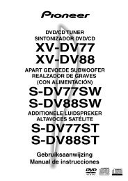
To unlock and open the vehicle:<br />
Press button q,<br />
pull door handle<br />
6 Door locks – see page 47,<br />
keys – see page 28,<br />
electronic im mobiliser – see page 29,<br />
ra dio remote control – see page 30,<br />
central locking – see page 38,<br />
anti-theft protection 3 – see page 39,<br />
Vauxhall alarm system 3 – see page 44,<br />
TwinTop roof operation 3 – see page 56.<br />
Picture no: 17333t.tif<br />
To unlock and open the vehicle<br />
with the Open&Start System 3:<br />
Bring electronic key into the<br />
reception area of the vehicle,<br />
pull handle<br />
6 Open&Start System 3 – see page 32.
Picture no: 16969t.tif<br />
To unlock and o pen th e luggage<br />
<strong>com</strong>partment:<br />
Press button q on radio remote<br />
control, or for the<br />
Open&Start System 3:<br />
Bring electronic key into the<br />
reception area of the vehicle,<br />
pull button below handle<br />
6 Open&Start-System 3 – page 32,<br />
Radio remote control – page 30,<br />
Central locking system – page 38,<br />
Vauxhall alarm system 3 – page 44.<br />
<strong>Ofrecido</strong> <strong>por</strong> <strong>www</strong>.<strong>electromanuales</strong>.<strong>com</strong><br />
Picture no: 16970t.tif<br />
To adjust front seat:<br />
Pull h andle, slide seat,<br />
release handle<br />
6 Seat – page 64, seat position – page 67.<br />
9 Warning<br />
Im<strong>por</strong>tant: Do not sit nearer than 10<br />
inches (25 cm ) from the steering wheel, to<br />
permit safe airbag deployment.<br />
In Brief<br />
Picture no: 16971t.tif<br />
Adjust front seat backrests:<br />
Turn handwheel<br />
Move backrest to suit seating position.<br />
Do not lea n on seat backrest whilst<br />
adjusting it.<br />
6 Seat – page 64, seat position – page 67.<br />
3
4 In Brief<br />
Picture no: 16973t.tif<br />
To adjust front seat height 3:<br />
Operate lever on outboard side of<br />
seat<br />
Pump action on lever<br />
up: seat higher<br />
down: seat lower<br />
6 Seat – page 64, sea t position – page 67.<br />
<strong>Ofrecido</strong> <strong>por</strong> <strong>www</strong>.<strong>electromanuales</strong>.<strong>com</strong><br />
Picture no: 16974t.tif<br />
To adjust front seat inclination 3:<br />
Pull inner lever on front of seat,<br />
adjust inclination, release lever,<br />
engage seat in position<br />
Adjust the inclination by distributing body<br />
weight.<br />
6 Seat – page 64, seat position – page 67.<br />
Picture no: 16975t.tif<br />
Tip the front seat backs<br />
forward 3:<br />
Lift release lever,<br />
tilt seat back forward,<br />
lower release lever,<br />
seat back is en gaged in tilted<br />
position3, slide seat forwards 3<br />
To straighten the seat, slide back and it<br />
engages in its original position 3. Raise<br />
release lever 3 , straighten seat ba ck, lower<br />
release lever, seat back eng ages.<br />
The seat back can only be tipped forwards<br />
from an upright position.<br />
Panoramic windscreen 3: before folding<br />
the seat, push the head restraints dow n<br />
and close the sun visors.<br />
6 Seat – page 64.
Picture no: 16976t.tif<br />
To adjust head restraint height of<br />
front and rear outboard seats:<br />
Press button to release, adjust<br />
height, engage in position<br />
6 Head restraints – see page 68,<br />
adjust rear centre head restraint – see<br />
page 68,<br />
head restraint position – see page 69,<br />
head restraint removal – see page 69.<br />
<strong>Ofrecido</strong> <strong>por</strong> <strong>www</strong>.<strong>electromanuales</strong>.<strong>com</strong><br />
Picture no: 16981t.tif<br />
To fit seat belt:<br />
Draw seat belt smoothly from<br />
inertia reel, guide over shoulder<br />
and engage in buckle<br />
The seat belt must not be twisted at any<br />
point. The lap belt m ust lie snugly against<br />
the body. The front seat backrests must not<br />
be tilted back too far (re<strong>com</strong>mended m ax.<br />
tilting angle approx. 25°).<br />
To relea se belt, press red button on belt<br />
buckle.<br />
6 Three-point seat belts – see page 85,<br />
Vauxhall Full Size airbag system –<br />
see page 92,<br />
seat position – see page 67.<br />
In Brief<br />
5
6 In Brief<br />
Picture no: 16977t.tif<br />
Adjusting interior mirror:<br />
Swivel mirror housing<br />
Swivel lever on underside of mirror housing<br />
to red uce daz zle a t nig ht.<br />
6 Mirrors – p age 48,<br />
automatic anti-dazzle interior mirror –<br />
page 49.<br />
<strong>Ofrecido</strong> <strong>por</strong> <strong>www</strong>.<strong>electromanuales</strong>.<strong>com</strong><br />
Picture no: 16978t.tif<br />
To adjust exterior mirrors<br />
manually:<br />
From inside, swivel lever in<br />
required direction<br />
6 Mirrors – see page 48,<br />
aspherical exterior mirror – see page 48,<br />
folding exterior m irror – page 48,<br />
heated exterior mirror – page 157.<br />
Picture no: 18437T.tif<br />
Electrical exterior mirrors 3<br />
adjust:<br />
Four-way switch in driver’s door<br />
Press mirror switch right or left: Four-way<br />
switch adjusts corresponding mirror.<br />
6 Mirrors – see page 48,<br />
aspherical exterior mirror – see page 48,<br />
folding exterior mirror – page 48,<br />
heated exterior m irror – page 157.
Picture no: 16982t.tif<br />
Steering wheel lock and ignition:<br />
Turn key to position 1. Move<br />
steering wheel somewhat to<br />
release loc k<br />
Positions:<br />
0 = Ignition off<br />
1 = Steering released, ignition off<br />
2 = Ignition on<br />
for diesel engines: preheating<br />
3 = Starting<br />
6 Starting – pa ge 17,<br />
electronic immobiliser – page 29,<br />
parking the vehicle – page 18.<br />
<strong>Ofrecido</strong> <strong>por</strong> <strong>www</strong>.<strong>electromanuales</strong>.<strong>com</strong><br />
Picture no: 17033t.tif<br />
Steering wheel lock and ignition<br />
on vehicles with Open&Start<br />
system 3:<br />
Make sure electronic key is in the<br />
interior reception range and<br />
press the Start/Stop button.<br />
Disengage the steering wheel<br />
lock by moving the steering wheel<br />
slightly<br />
To start the vehicle, also operate brake or<br />
clutch p edal.<br />
To lock the steering wheel, switch ignition<br />
off by pressing the Start/Stop button, open<br />
driver’s door and engage steering w heel.<br />
Do not allow vehicle to move whilst doing<br />
this.<br />
6 Starting – page 17,<br />
electronic im mobiliser – page 29,<br />
parking the vehicle – pag e 18.<br />
In Brief<br />
Picture no: 17328t.tif<br />
Steering wheel adjustment:<br />
Move lever down, adjust height<br />
and distance, move lever up,<br />
engage<br />
Adjust steering wheel only when vehicle is<br />
stationary and steering colum n lock is<br />
released.<br />
6 Vauxhall Full Size airbag system –<br />
page 92.<br />
7
8 In Brief<br />
<strong>Ofrecido</strong> <strong>por</strong> <strong>www</strong>.<strong>electromanuales</strong>.<strong>com</strong>
Page<br />
1 Side air v ents .................................. 156<br />
2 Front pa ssenger airbag .................. 93<br />
3 Centre air v ents ............................. 156<br />
4 Central information display for<br />
time, date, outside temperature,<br />
infotainment system 3 ,<br />
check control 3 .............................. 138<br />
Trip <strong>com</strong>puter 3 .....................128, 134<br />
Clim ate control system 3 ............. 168<br />
5 Heated seat (left) 3 ...................... 157<br />
Deflation<br />
detection system 3 ........................ 217<br />
Tyre pressure<br />
monitoring system 3 ...................... 218<br />
Parking distance sensor 3 ............ 214<br />
Haza rd warning lights .....................12<br />
Central locking system ....................40<br />
SPORT mode 3 ............................... 210<br />
Heated seat (right) 3 ................... 157<br />
<strong>Ofrecido</strong> <strong>por</strong> <strong>www</strong>.<strong>electromanuales</strong>.<strong>com</strong><br />
Pa ge<br />
6 Turn signal light, headlight flash,<br />
dipped bea m, high beam ............... 11<br />
Switch off delay on 3 ..................... 148<br />
Parking lights 3 ............................. 148<br />
Cruise control 3 ............................. 212<br />
7 Remote control<br />
on steering whee l 3 .......................151<br />
8 Instruments ..................................... 112<br />
9 Horn .................................................. 12<br />
Driv er’s Airbag ................................ 93<br />
10 Windscreen wiper,<br />
windscreen wash system,<br />
headlight wash system 3 and<br />
re ar window w ash<br />
system .................................12, 13, 141<br />
11 Pa rk ing lights, dipped beam ........ 143<br />
Instrument illumination ................. 148<br />
Fog tail lig ht ................................... 145<br />
Fog lights 3 .................................... 145<br />
Headlight range adjustment 3 .... 146<br />
12 Bonnet release lev er ...................... 241<br />
In Brief<br />
9<br />
Page<br />
13 Starter switch<br />
with imm ob iliser ................................. 7<br />
and<br />
sensor panel for emergency operation<br />
Open&Start system 3 ..................... 35<br />
14 Accelerator pedal .................. 199, 199<br />
15 Brake pedal ................... 199, 221, 221<br />
16 Clutch pedal3 ............................... 199<br />
17 Steering w heel a djustment ............... 7<br />
18 Start/stop button 3 .................. 17, 32<br />
19 Ashtray 3 ....................................... 108<br />
Cigarette lighter 3 ........................ 107<br />
20 Clim ate c ontrol ............................. 154<br />
21 Infotainment system 3 ................. 151<br />
22 Glove <strong>com</strong>partment ....... 34, 110, 156
10 In Brief<br />
Control indicators<br />
0 O pen&S tart sy stem , fault ,<br />
see pages 32, 112.<br />
I<br />
R<br />
v<br />
v<br />
X<br />
Q<br />
p<br />
W<br />
Engine oil pressure,<br />
see page 113.<br />
Brak e sy stem , clut ch sy stem,<br />
see pages 114, 221, 302.<br />
Airb ag sy st em s, belt tensi oners,<br />
deployable anti-roll ba rs 3,<br />
see pages 87, 98, 104.<br />
Elec tronic St abili ty Progra mme<br />
(ESP® Plus ) 3,<br />
see page 208.<br />
Seat bel t 3,<br />
see pages 88, 114.<br />
Door open,<br />
see page 115.<br />
Alternat or,<br />
see page 115.<br />
Coola nt temperat ure,<br />
see pages 115, 300.<br />
<strong>Ofrecido</strong> <strong>por</strong> <strong>www</strong>.<strong>electromanuales</strong>.<strong>com</strong><br />
A<br />
j<br />
Engine electronics,<br />
gearbox electronics3,<br />
immob iliser,<br />
Diesel fuel filter 3 ,<br />
fault,<br />
see pages 29, 115, 182, 188,<br />
196, 206.<br />
Easytronic 3 , start engine 3<br />
see pages 115, 177.<br />
IDS+ Continuous Damping Control 3 ,<br />
SPORT m ode 3,<br />
see pages 210, 211.<br />
S<br />
8<br />
r<br />
O<br />
Y<br />
><br />
C<br />
r<br />
Engine oil l evel 3,<br />
see pages 116, 298.<br />
Exterior light s,<br />
see pages 116, 143.<br />
Pa rking distance sensor 3 ,<br />
see page 214.<br />
Turn sig nal lig ht s,<br />
see pages 11, 116.<br />
Fuel level,<br />
see pages 116, 119, 202.<br />
Fog lights 3,<br />
see pages 117, 145.<br />
Main beam,<br />
see pages 11, 117.<br />
Fog t ail li ght,<br />
see pages 117, 145.<br />
T<br />
1<br />
y<br />
Z<br />
u<br />
!<br />
w<br />
B<br />
m<br />
Winter programme of<br />
automatic transmission 3 or<br />
Easytronic 3,<br />
see pages 180, 186, 193.<br />
SPORT mode of automatic<br />
tr ansm issi on 3 or Easytronic 3,<br />
see pages 179, 185, 192.<br />
Seat occupancy recognition 3,<br />
see page 99.<br />
Exhaust emission 3 ,<br />
see pages 117, 205.<br />
Anti -lock Bra ke Syst em ,<br />
see page 223.<br />
Preheating system 3,<br />
Diesel parti cle filter 3,<br />
see page 118.<br />
Deflation detection system 3 ,<br />
tyre pressure monitoring<br />
system 3,<br />
see pages 118, 217, 219.<br />
Ad aptive for ward lighting 3,<br />
fault<br />
see pages 147, 150.<br />
Cruise control 3,<br />
see page 212.
Picture no: 16986t.tif<br />
Light switch:<br />
7 = Off<br />
8 = Parking lights<br />
9 = Dipped beam or main<br />
beam<br />
AUTO = Automatic dipped<br />
beam activation3 Press button:<br />
> = Fog lights 3<br />
r = Fog tail light<br />
6 Lighting – p age 143,<br />
headlig ht control indicator – page 140.<br />
<strong>Ofrecido</strong> <strong>por</strong> <strong>www</strong>.<strong>electromanuales</strong>.<strong>com</strong><br />
Picture no: 16987t.tif<br />
Headlight flash, main beam and<br />
dipped beam:<br />
Headlight<br />
flash<br />
= Pull stalk<br />
towards<br />
steering wheel<br />
Main beam = Push stalk<br />
Dipped beam = Push stalk<br />
forwards again<br />
or pull toward<br />
steering wheel<br />
6 Main beam, headlight flash – page 144.<br />
In Brief<br />
Picture no: 16989t.tif<br />
Switch on tu rn signal lights:<br />
Right = Move stalk up<br />
Left = Move stalk down<br />
6 Turn signal lights – page 144.<br />
11
12 In Brief<br />
<strong>Ofrecido</strong> <strong>por</strong> <strong>www</strong>.<strong>electromanuales</strong>.<strong>com</strong><br />
Picture no: 16991t.tif<br />
Picture no: 16992t.tif<br />
Picture no: 16993t.tif<br />
Hazard warning lights:<br />
Activate horn:<br />
Windscreen wiper:<br />
on = press ¨<br />
off = press ¨ again<br />
6 Hazard w arning lights – page 145.<br />
Press j in centre of steering<br />
wh eel<br />
6 Vauxhall Full Size airbag system –<br />
page 93,<br />
remote control on steering wheel3 –<br />
Move stalk upward<br />
§ = off<br />
$ = timed interval wipe<br />
% = slow<br />
page 151.<br />
& = fast<br />
Move stalk down from position §: Single<br />
swipe.<br />
6 Windscreen wiper – page 141,<br />
adjustable tim ed interval wipe 3 –<br />
page 141,<br />
further notes – pages 291, 303.
Picture no: 16995t.tif<br />
Automatic wiping with rain<br />
sensor 3:<br />
Move stalk upward<br />
$ = automatic wiping with<br />
rain sensor<br />
§ = off<br />
6 Windscreen wiper – page 141,<br />
further notes – pages 291, 303.<br />
<strong>Ofrecido</strong> <strong>por</strong> <strong>www</strong>.<strong>electromanuales</strong>.<strong>com</strong><br />
Picture no: 16996t.tif<br />
Operating windscreen and<br />
headlight wash systems 3:<br />
Pull stalk towards steering wheel<br />
6 Windscreen and headlight w ash sy stems<br />
– page 142,<br />
further notes – pages 291, 303<br />
In Brief<br />
13<br />
Picture no: 16997t.tif<br />
Activate rear screen wiper 3 an d<br />
wash system 3:<br />
Wiper on = Stalk forwards<br />
Wiper on = Stalk forwards<br />
again<br />
Wash = Hold stalk fully<br />
fo rwards<br />
6 Rear screen wiper and wa sh system –<br />
page 142,<br />
further notes – pages 291, 303.
14 In Brief<br />
Picture no: 16998t.tif<br />
Heated rear window,<br />
heated exterior mirrors:<br />
on = press Ü<br />
off = press Ü again<br />
6 Air conditioning – page 154,<br />
heated rear window – page 157.<br />
<strong>Ofrecido</strong> <strong>por</strong> <strong>www</strong>.<strong>electromanuales</strong>.<strong>com</strong><br />
Picture no: 16999t.tif<br />
To demist or defrost windows:<br />
Set air distribution to l,<br />
ro tary switch for temperature<br />
and air flow clockwise;<br />
Air conditioning system 3:<br />
also press bu ttons n;<br />
Automatic air conditioning<br />
system 3:<br />
press buttons n andv,<br />
turn rotary switch for<br />
temperature clockwise,<br />
air flo w to A;<br />
Climate control system 3:<br />
press button V<br />
6 Clim ate control system 3 – p age 154.<br />
Picture no: 17000t.tif<br />
Set automatic mode on climate<br />
control system 3:<br />
Press AUTO,<br />
pre-select temperature with<br />
rotary knob,<br />
open air vents<br />
6 Climate control system 3 – page 168.
Picture no: 17001t.tif<br />
Manual transmission:<br />
Reverse: with the vehicle stationary, wait<br />
3 seconds after de-clutching and then pull<br />
up the button on the selector lever and<br />
enga ge the gea r.<br />
If the gear does not engage, set the lever in<br />
neutral, release the clutch pedal and<br />
depress again; then repeat gear selection.<br />
<strong>Ofrecido</strong> <strong>por</strong> <strong>www</strong>.<strong>electromanuales</strong>.<strong>com</strong><br />
Picture no: 17002t.tif<br />
Easytronic 3:<br />
N = Idle<br />
o = Drive position<br />
+ = Higher gear<br />
- = Lower gear<br />
A/M = Chan ge between<br />
Automatic and Manual<br />
mode<br />
R = Reverse gear (with<br />
selector lever lock)<br />
The selector lever must always be moved in<br />
the appropriate direction as far as it will<br />
go. Upon release, it autom atically returns<br />
to the centre position. Pay heed to the<br />
gear/mode indicator in the transmission<br />
display.<br />
The foot brake must be depressed when<br />
starting.<br />
6 Ea sy tronic 3 – page 176.<br />
In Brief<br />
15<br />
Picture no: 17003t.tif<br />
Automatic transmission 3:<br />
P = Park position<br />
R = Reverse gear<br />
N = Neutral (idle)<br />
D = Automatic gear selection<br />
3 = 1st to 3rd gear<br />
2 = 1st an d 2nd gear<br />
1 = 1st gear<br />
Starting only possible in P or N. To m ov e<br />
from P, switch on ignition, depress foot<br />
brake and press button on selector lever.<br />
Press button on selector lever to engage P<br />
or R.<br />
P only when v ehicle is stationary, first<br />
apply handbrake<br />
R only when v ehicle is stationary<br />
6 Automatic transmission 3 – page 184.
16 In Brief<br />
Picture no: 17330t.tif<br />
Automatic transmission<br />
with ActiveSelect 3:<br />
P = Park position<br />
R = Reverse gear<br />
N = Neutral (idle)<br />
D = Au to matic gear selection<br />
Selector lever in D to left:<br />
Manual mode<br />
+ = Higher gear<br />
- = Lower gear<br />
P or N must be engaged when starting.<br />
To move from P or N , switch on ignition,<br />
depress foot brake and press button on<br />
selector lever.<br />
<strong>Ofrecido</strong> <strong>por</strong> <strong>www</strong>.<strong>electromanuales</strong>.<strong>com</strong><br />
To se lect P or R, press button on selector<br />
lever.<br />
P only w ith vehicle stopped, first apply<br />
handbrake<br />
R only w hen vehicle is stationary<br />
6 Automatic transmission 3 – see<br />
page 184.<br />
Before starting off, check:<br />
z Tyre pressure and tyre condition –<br />
pages 225, 337.<br />
z Engine oil level and fluid levels in engine<br />
<strong>com</strong>partment – see pages 298 to 305.<br />
z All windows, mirrors, exterior lighting<br />
and number plates are free from dirt,<br />
snow and ice a nd operational.<br />
z Do not place any objects in front of the<br />
rear window, on the instrument panel or<br />
in the area in which the airbags inflate.<br />
z Seats, seat belts and mirrors are<br />
correctly a djusted .<br />
z Check brakes.
Picture no: 17005t.tif<br />
To start engine:<br />
Operate clutch and brake,<br />
automatic transmission 3 in P<br />
or N,<br />
Easytronic3: Depress brake,<br />
do not accelerate,<br />
Petrol engine: Turn key to 3;<br />
Diesel engine: Turn key to 2, when<br />
control indicator ! go es out1) turn key to 3; release key once<br />
engine is running<br />
Before restarting or switching off the<br />
engine, turn key back to 0.<br />
To switch on the ignition, only turn the key<br />
to 2.<br />
6 Electronic imm obiliser – page 29,<br />
Diesel fuel system – page 242.<br />
<strong>Ofrecido</strong> <strong>por</strong> <strong>www</strong>.<strong>electromanuales</strong>.<strong>com</strong><br />
Picture no: 17033t.tif<br />
To start engine with Open&Start<br />
system 3:<br />
The electronic key must be inside<br />
reception area inside the car,<br />
operate clutch or brake,<br />
Automatic transmission 3 in P<br />
or N, Easytronic 3: Depress brake,<br />
do not accelerate,<br />
Petrol engine: Press button;<br />
Diesel engine: Briefly press<br />
button; when control indicator !<br />
goes out 1) press button again for<br />
1 second; release button once<br />
engine is running<br />
1) Preheating system switches on only if outside<br />
temperature is low.<br />
In Brief<br />
17<br />
Press button again to repeat the starting<br />
procedure or switch off the engine.<br />
To turn on the ignition, do not press the<br />
brake or clutch pedal; just press the button<br />
briefly.<br />
Do not start unless vehicle is stationary.<br />
6 Open&Start-System 3 – page 32,<br />
Electronic immobiliser – page 29,<br />
Diesel fuel system – page 242.
18 In Brief<br />
Picture no: 17006t.tif<br />
Releasing the hand brake:<br />
Raise lever slightly,<br />
press lock button,<br />
lower lever fully<br />
6 Handbrake – pa ge 222.<br />
<strong>Ofrecido</strong> <strong>por</strong> <strong>www</strong>.<strong>electromanuales</strong>.<strong>com</strong><br />
Picture no: 17007t.tif<br />
Parking the vehicle:<br />
Apply hand brake firmly,<br />
engine off, ignition off,<br />
lock steering wheel,<br />
loc k vehicle<br />
To lock, press button p of ra dio remote<br />
control for Open&Start system 3 touch<br />
se nsor in a door handle on the front doors.<br />
With Open&Start system 3, the driver’s<br />
door must b e opened to lock the steering<br />
wheel.<br />
To activate the mechanical anti-theft<br />
locking system 3 and the Vauxhall alarm<br />
system 3 press button p tw ic e or with<br />
Open&Start system 3 touch sensor in one<br />
of the front door handles twice.<br />
6 Further information – see pages 29, 198,<br />
Open&Start system – page32, radio remote control – see page 30,<br />
central locking system – see page 38,<br />
Vauxhall alarm system 3 – see page 44,<br />
TwinTop roof operation 3 – page 56.<br />
Vehicle de<strong>com</strong> missioning – see page 307.
Advice when parking:<br />
z Do not p ark the v ehicle on an easy<br />
flam mable surface. The high<br />
temperature of the exhaust system could<br />
ignite the surface.<br />
z Alwa ys apply the hand brake firmly.<br />
Ap ply the ha nd brake as firm ly as<br />
possible on uphill or downhill slopes.<br />
To reduce operating forces, depress foot<br />
brake at the same time.<br />
z Close the windows and sun roof 3 or<br />
Tw inTop.<br />
z For manual transmission, select first or<br />
reverse; for automatic transmission 3<br />
move selector lever to P, for Easytronic3 select first or reverse before switching off<br />
the ignition (note gear display, see<br />
pages 177, 184, 191).<br />
<strong>Ofrecido</strong> <strong>por</strong> <strong>www</strong>.<strong>electromanuales</strong>.<strong>com</strong><br />
z O n vehicle s with automa tic<br />
transmission 3 the key can only be<br />
withdrawn when the selector lever is in<br />
position P. For the Open&Start System 3,<br />
"P" flashes in the gear display for a few<br />
seconds if P is not engaged or the<br />
handbrake is not applied.<br />
z On vehicles with Easytronic3 control<br />
indicator R flashes for a few seconds<br />
after the ignition is switched off if the<br />
hand brake has not been applied– see<br />
page 182.<br />
z With the Open&Start system 3 the<br />
engine can only be switched off when the<br />
car is stationary.<br />
z Turn steering wheel until the steering<br />
lock perceptibly engages (Anti-theft<br />
protection) after first withdrawing the<br />
ignition key; for Open&Start-System 3<br />
switch off ignition and open driver’s<br />
door.<br />
z The engine cooling fans may run after<br />
the engine has been switched off – see<br />
page 297.<br />
6 Further information – pages 306, 307.<br />
In Brief<br />
19<br />
That was the most im<strong>por</strong>tant<br />
information in brief for your first<br />
drive in your vehicle.<br />
The other pages o f this chapter<br />
contain a summary of the<br />
noteworthy functions of your<br />
vehicle.<br />
The remain ing ch apters of the<br />
Owner’s Manual contain<br />
im<strong>por</strong>tant information on<br />
operation, safety and<br />
maintenance as well as a<br />
<strong>com</strong>plete index.
20 In Brief<br />
Picture no: 17009t.tif<br />
Vauxhall Full Size airbag system<br />
The Vauxhall Full Size airbag system<br />
consists of several separate sy stems.<br />
Front airbag system<br />
The front airbag system will be triggered in<br />
the event of a serious accident involving a<br />
frontal impact and forms safety cushions<br />
for the driver and front passenger. The<br />
forward movement of the driver and front<br />
passenger is checked and the risk of<br />
injuries to the upper body a nd head<br />
thereby substantially reduced.<br />
<strong>Ofrecido</strong> <strong>por</strong> <strong>www</strong>.<strong>electromanuales</strong>.<strong>com</strong><br />
Picture no: 17110t.tif<br />
Side airbag system 3<br />
The side airbag is triggered in the event of<br />
a side-on collision to form a safety cushion<br />
for the driver or front passenger in the<br />
respective door area. This substantially<br />
reduces the risk of injury to the upper body<br />
and pelvis.<br />
Picture no: 17351t.tif<br />
Cur tain airbag system 3<br />
The curtain airbag system triggers in case<br />
of a side-on collision and provides a safety<br />
barrier in the head area on the respective<br />
side of the vehicle. This reduces the risk of<br />
injury to the hea d considerably in case of a<br />
side-on collision.<br />
6 Vauxhall Full Size airbag system –<br />
page 92.
Picture no: 17011t.tif<br />
Active head restraints 3 on front<br />
seats<br />
In the event of a rear-end impact, the<br />
active head restraints tilt forward a little.<br />
The head is more effectiv ely sup<strong>por</strong>ted by<br />
the head restraint and the danger of<br />
injuries caused by whiplash in the neck<br />
area is reduced.<br />
Active head restraints are identified by the<br />
lettering ACTIVE on the head restraint<br />
guide sleeves.<br />
6 Headrests – page 68.<br />
<strong>Ofrecido</strong> <strong>por</strong> <strong>www</strong>.<strong>electromanuales</strong>.<strong>com</strong><br />
Picture no: S0013209.tif<br />
Operating menus in th e<br />
information display 3<br />
Menu options are selected using menus<br />
and using the arrow keys the multi-function<br />
button of the Infotainment system 3 or the<br />
left-hand adjuster wheel 3 on the steering<br />
wheel. The respective menu options are<br />
shown on the display.<br />
Select with the arrow keys 3: press right or<br />
left key.<br />
In Brief<br />
21<br />
Picture no: 17013t.tif<br />
Selection using multi-function button 3:<br />
rotate and press multi-function button.<br />
To exit a m enu, turn the m ulti-function<br />
button left or right to Return or Main and<br />
select.<br />
Selection with left adjuster wheel on<br />
steering wheel 3: turn adjuster wheel and<br />
press.<br />
6 Information Display – page 122.
22 In Brief<br />
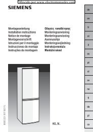
Ü Board Computer 19,5° 19:36<br />
BC 1 All values<br />
BC 2<br />
Timer<br />
Tyres<br />
1<br />
257.0 miles<br />
Ø 40 mph<br />
8<br />
7.0 gal<br />
Ø 31.0 mpg<br />
Picture no: 17344t.tif<br />
Trip <strong>com</strong>puter 3<br />
The trip <strong>com</strong>puters provide information on<br />
driving data, which is continually recorded<br />
and evaluated electronically.<br />
Functions:<br />
z Range<br />
z Instantaneous consumption<br />
z Distance tra velled<br />
z Av erage speed<br />
z Effective consump tion<br />
z Average consumption<br />
z Stop watch<br />
z Tyre pressure 3<br />
6 Trip <strong>com</strong>puter 3 – pa ges 128, 134.<br />
<strong>Ofrecido</strong> <strong>por</strong> <strong>www</strong>.<strong>electromanuales</strong>.<strong>com</strong><br />
Coolant level<br />
check<br />
OK<br />
Picture no: 17339t.tif<br />
Check co ntro l 3<br />
The check control software monitors<br />
z Fluid levels<br />
z Tyre pressure 3<br />
z Radio remote control battery<br />
z Vauxhall alarm system 3<br />
z Im<strong>por</strong>tant exterior lights, including<br />
cables and fuses.<br />
6 Check-Control3 – page 138.<br />
Picture no: 17015t.tif<br />
Remote control on steering<br />
wheel 3<br />
The functions of the infotainment system 3<br />
and the informa tion display can be<br />
operated with the remote control on the<br />
steering wheel.<br />
Further information is available in the<br />
infotainm ent system operating<br />
instructions.<br />
6 Remote control on steering wheel 3 –<br />
page 151, Infotainment System –<br />
page 151.
Picture no: 17026t.tif<br />
Twin Audio 3<br />
Twin Audio allows rear seat occupants the<br />
choice between the audio source played on<br />
the infotainment system or a separate<br />
audio source.<br />
Only an audio source that is not currently<br />
active on the infotainment system can be<br />
controlled using Twin Audio.<br />
Two headphone connections are available,<br />
with separate volume controls.<br />
Further information is available in the<br />
infotainment system operating<br />
instructions.<br />
6 Tw in Audio 3 – pa ge 152.<br />
<strong>Ofrecido</strong> <strong>por</strong> <strong>www</strong>.<strong>electromanuales</strong>.<strong>com</strong><br />
Picture no: 17333t.tif<br />
Open&Start system with<br />
electronic key and radio remove<br />
control 3<br />
The Open&Start system allows the vehicle<br />
to be locked and unlocked, including<br />
mechanical a nti-theft locking system 3<br />
and the Vauxhall alarm system 3 without a<br />
mechanical key and the engine to be<br />
started and stopped using a start/stop<br />
button. All the driver has to do is carry the<br />
electronic key around with him.<br />
6 Open&Start S ystem 3 – page 32.<br />
In Brief<br />
23<br />
Picture no: 17961t.tif<br />
S<strong>por</strong>t mode 3<br />
To activate<br />
Press button SPORT.<br />
SPORT mode is used to change<br />
dam ping 3, steering 3, throttle<br />
application and the shift point for<br />
Easytronic3 and automatic<br />
transmission 3 while driving.<br />
Damping and steering be<strong>com</strong>e more direct<br />
and provide better contact with the road<br />
surface. The engine reacts more quickly to<br />
accelerator movements.<br />
With Easytronic 3 and automatic<br />
transmission 3, the shift times are<br />
shortened and shifting takes place at<br />
higher revs (not with cruise control<br />
enabled 3).<br />
6 S<strong>por</strong>t mode 3 – page 210.
24 In Brief<br />
Picture no: 17018t.tif<br />
Deflation Detection System<br />
(DDS) 3<br />
The deflation detection system<br />
continuously monitors the speed of all<br />
wheels while driving. If a tyre loses<br />
pressure, it grows smaller and therefore<br />
rotates more quickly than the other wheels.<br />
If the system detects a difference in speed,<br />
the control indicator w illuminates in red.<br />
<strong>Ofrecido</strong> <strong>por</strong> <strong>www</strong>.<strong>electromanuales</strong>.<strong>com</strong><br />
Picture no: 17019t.tif<br />
After tyre pressure is corrected or a tyre or<br />
wheel is changed, the system m ust be<br />
initialised by pressing the DDS button.<br />
6 Tyre deflation detection system 3 –<br />
page 217.<br />
Ü Board Computer<br />
BC 1<br />
BC 2<br />
Timer<br />
Tyres<br />
Picture no: 17334t.tif<br />
Tyre pressure monitoring<br />
system 3<br />
The tyre pressure monitoring system<br />
continually checks the pressure and speed<br />
of all four wheels while driving.<br />
A pressure sensor is insta lled in ea ch wheel.<br />
The inflation pressures of the individual<br />
wheels are transmitted to a controller,<br />
where they are <strong>com</strong>pared.<br />
The current tyre pressures can be<br />
displayed on the graphical informa tion<br />
display or the colour information display 3.<br />
Deviating tyre pressures are displayed in<br />
the form of messages on the information<br />
display whilst driving.<br />
6 Tyre pressure monitoring system 3 –<br />
page 217.
Picture no: 17126t.tif<br />
Adaptive Forward Lighting<br />
(AFL) 3<br />
improves lighting in curves (curve lighting)<br />
on vehicles with Bi-Xenon headlight<br />
system.<br />
<strong>Ofrecido</strong> <strong>por</strong> <strong>www</strong>.<strong>electromanuales</strong>.<strong>com</strong><br />
Picture no:<br />
Curve lig hting<br />
The Xenon light beam pivots based on<br />
steering wheel position and speed (from<br />
approx. 6 m ph / 10 km /h).<br />
Motorwa y lig hting<br />
At higher speeds and continuous straight<br />
ahead travel, the dipped beam<br />
autom atically raises slightly, thereby<br />
increasing headlight range.<br />
6 Adaptive driving lights 3 – page 147.<br />
In Brief<br />
25<br />
Picture no: 17979t.tif<br />
Panoramic windscreen 3<br />
To open:<br />
Turn the handle to the right and move the<br />
roof lining rearward to a suitable position.<br />
To close:<br />
Move the roof lining forward to a suitable<br />
position. When moved all the w ay forw ard,<br />
the roof lining engages in position.<br />
6 Panoramic roof 3 – page 53.
26 In Brief<br />
Picture no: 17203t.tif<br />
Parking distance sensor3 When rev erse gear is selected, the Pa rk ing<br />
distance sensor sw itches itself on<br />
automatically.<br />
The parking distance sensor can also be<br />
activated at speeds of less than 15 mph (25<br />
km/h) by pressing the r button on the<br />
instrument panel.<br />
If the vehicle approaches an obstacle when<br />
reversing, a series of signals can be heard<br />
in the vehicle interior. The interva l between<br />
the signals be<strong>com</strong>es shorter as the<br />
distance is reduced. If the distance is less<br />
than 30 cm, the signal w ill be continuous.<br />
6 Parking distance sensor 3 – page 214.<br />
<strong>Ofrecido</strong> <strong>por</strong> <strong>www</strong>.<strong>electromanuales</strong>.<strong>com</strong><br />
Picture no: 17092t.tif<br />
Cargo box 3<br />
Collapsible box to divide the lugga ge<br />
<strong>com</strong>partment.<br />
The cargo box may only be loaded when<br />
the backrests a re eng aged in an upright<br />
position.<br />
When removing, start with the right half.<br />
6 Cargo Box3 – page 81.<br />
Picture no: 17087t.tif<br />
FlexOrganizer 3<br />
The side walls contain retaining strips,<br />
where various <strong>com</strong>ponents can be<br />
attached to divide the luggage<br />
<strong>com</strong>pa rtm ent or fasten loads.<br />
The sy stem consists of<br />
z Adapters<br />
z Variable partition net<br />
z Mesh pockets for the side walls<br />
z Hooks in the luggage <strong>com</strong>partment<br />
6 FlexOrg aniz er 3 – page 80.
Picture no: 17980t.tif<br />
Luggage <strong>com</strong>partment cover,<br />
Estate<br />
To open:<br />
Press ha ndle on luggage <strong>com</strong>pa rtm ent<br />
cover down. The cover automa tica lly<br />
unrolls.<br />
6 Luggage <strong>com</strong>pa rtm ent cover 3 –<br />
page 76.<br />
<strong>Ofrecido</strong> <strong>por</strong> <strong>www</strong>.<strong>electromanuales</strong>.<strong>com</strong><br />
Picture no: 17981t.tif<br />
Astra TwinTop<br />
With TwinTop, a convertible hardtop, Astra<br />
unites the benefits of a coupe with those of<br />
a convertible.<br />
To optimise safety, the Astra TwinTop is<br />
equipped with a rollover protection system<br />
with reinforced windscreen frame and the<br />
choice of fixed or deployable anti-roll bars<br />
in addition to the front and side airbag<br />
sy stems.<br />
In Brief<br />
27<br />
The roof is operated with the buttons on<br />
the roof console above the mirror or with<br />
the remote control.<br />
To improve luggage <strong>com</strong>pa rtm ent<br />
accessibility, the electric loading aid makes<br />
it possible to raise the open roof when it is<br />
stowed in the luggage <strong>com</strong>partment.<br />
6 TwinTop – see page 56.
28 Keys, Doors, Windows, TwinTop<br />
Keys, Doors, Windows,<br />
TwinTop<br />
Replacem ent keys ............................... 28<br />
Ca r Pass................................................ 28<br />
Key with foldaw ay key section 3 ....... 28<br />
Electronic immobiliser.......................... 29<br />
Store personal vehicle settings in the<br />
vehicle key 3 ..................................... 30<br />
Radio remote control with 3<br />
mec hanical key ................................. 30<br />
Open&Start system 3 .......................... 32<br />
Central locking system ........................ 38<br />
Fault when locking or unlocking......... 42<br />
Lug gage <strong>com</strong>partment ....................... 43<br />
Vauxhall alarm system 3.................... 44<br />
Child safety locks 3 ............................. 47<br />
Exterior mirrors..................................... 48<br />
Interior mirror ....................................... 49<br />
Electric windows 3 ............................... 50<br />
Panoramic windscreen 3 .................... 53<br />
Sun roof 3 ............................................ 54<br />
TwinTop ................................................ 56<br />
<strong>Ofrecido</strong> <strong>por</strong> <strong>www</strong>.<strong>electromanuales</strong>.<strong>com</strong><br />
Replacement keys<br />
The key number is specified in the vehicle<br />
docum ents and in the Car Pass 3.<br />
The key is a constituent of the electronic<br />
immobiliser. Ordering keys from a Vauxhall<br />
Authorised Repairer guarantees problem -<br />
free operation of the electronic<br />
immobiliser.<br />
When electronic keys of the Open&Start<br />
system are being replaced, all keys must be<br />
handed to the dealer for programming.<br />
Keep the sp are k ey in a safe spot.<br />
Locks, see page291, Open&Start system,<br />
electronic k eys, see pa ge 32.<br />
Car Pass<br />
The Car Pass contains all of the vehicle’s<br />
data and should therefore not be k ept in<br />
the vehicle.<br />
Have your Car Pass on hand when<br />
consulting a Vaux hall Authorised Repairer.<br />
Picture no: 17027t.tif<br />
Key with foldaway key section 3<br />
Press button to extend. Press button to<br />
retract; key section eng ages audibly.
Picture no: 17349t.tif<br />
Electronic immobiliser<br />
The system checks whether the vehicle may<br />
be started with the mechanical key or<br />
electronic key of the Open&Start system 3<br />
that is being used. If the key is recognised<br />
as "authorised" the vehicle can be started.<br />
The check ta kes place via a transponder in<br />
the key.<br />
The electronic imm obiliser activates itself<br />
automatically after the key has been<br />
removed from the ignition or, with the<br />
Open&Start system 3, when the engine is<br />
switched off by pressing the Start/Stop<br />
button.<br />
The c od e number of the electronic<br />
immobiliser is given in the Car Pass.<br />
<strong>Ofrecido</strong> <strong>por</strong> <strong>www</strong>.<strong>electromanuales</strong>.<strong>com</strong><br />
Picture no: 17033t.tif<br />
Control i nd icator for imm obiliser A<br />
Control indica tor A illuminates briefly<br />
when the ig nition is sw itched on.<br />
If the control indicator flashes when the<br />
ignition is on, there is a fault in the system;<br />
the engine cannot be started. Switch off<br />
the ignition and then repeat the start<br />
attempt.<br />
If the control indicator A continues to<br />
flash, try to start the engine using the<br />
second key and contact a workshop for<br />
assista nce.<br />
Keys, Doors, Windows, TwinTop<br />
29<br />
Picture no: 17028t.tif<br />
If control indicator A illuminate s afte r the<br />
engine is started, there is a fault in the<br />
engine electronics or transmission<br />
electronics3 (see pages 182, 188, 196, 206)<br />
or there is water in the diesel fuel filter 3 (see<br />
page 300).<br />
Note<br />
The immobiliser does not lock the doors.<br />
Therefore, after leaving the vehicle always<br />
lock it and switch on the Vauxhall alarm<br />
system 3 – see pages 38, 45.
30 Keys, Doors, Windows, TwinTop<br />
Store personal vehicle settings in<br />
the vehicle key 3<br />
The last settings selected<br />
z for the climate control system 3<br />
z information display 3<br />
z Infotainment system 3<br />
z instrum ent illumination<br />
are stored autom atically depending on the<br />
vehic le key used .<br />
Different settings stored for each vehicle<br />
key are retrieved automatically on use of<br />
the v ehicle key concerned .<br />
Each time the vehicle is locked, the settings<br />
are sa ved again.<br />
<strong>Ofrecido</strong> <strong>por</strong> <strong>www</strong>.<strong>electromanuales</strong>.<strong>com</strong><br />
Picture no: 17029t.tif<br />
Radio remote control with 3<br />
mechanical key<br />
Depending on vehicle equipm ent level, one<br />
of the rem ote controls shown on this page<br />
will be used.<br />
Radio remote control in version with<br />
Open&S tart sy stem 3 see page 32.<br />
The radio remote control is integrated in<br />
the key.<br />
Used to operate:<br />
z central locking system,<br />
z mechanical anti-theft locking system 3,<br />
z Vauxhall alarm system 3.<br />
Depending on the equipment level of the<br />
vehicle 3, the windows of vehicles with<br />
electric windows in all doors 3 can be<br />
opened or closed from outside using the<br />
ra dio remote control. Se e pa ge 41.<br />
Picture no: 17030t.tif<br />
On the Astra TwinTop, the roof can also be<br />
opened or closed with the remote<br />
control 3.<br />
The ra dio remote control has a rang e of<br />
app rox . 5 me tres. This ra ng e can be<br />
affected by outside influences. Aim the<br />
remote control at the vehicle to operate.<br />
Handle the radio remote control with care,<br />
protect it from moisture and high<br />
temperatures and avoid unnecessary<br />
operation.<br />
The hazard warning lights <strong>com</strong>e on to<br />
indicate that the remote control is<br />
operational.
Centra l locking, mechanic al anti-theft<br />
locking system 3,<br />
see page 38.<br />
Vauxhall alarm system 3,<br />
see page 44.<br />
Electric windows3, see page 50.<br />
Astra TwinTop,<br />
see page 56.<br />
<strong>Ofrecido</strong> <strong>por</strong> <strong>www</strong>.<strong>electromanuales</strong>.<strong>com</strong><br />
Fault<br />
If the centra l locking system ca nnot be<br />
operated with the radio remote control, it<br />
may be due to the following:<br />
z The ra nge of the ra dio remote control<br />
has been exceeded.<br />
z Radio remote control battery voltage is<br />
too low. Battery replacement - see right<br />
hand column.<br />
z Frequent, repeated op eration of the<br />
radio remote control outside the<br />
reception range of the vehicle (e.g. too<br />
far from vehicle, remote control is then<br />
no longer recognised). Remote control<br />
synchronisation - see right hand column.<br />
z If the central locking system is<br />
overloaded as a result of repeated<br />
operation at short intervals. The power<br />
supply is cut off for a brief period.<br />
z Interference from higher-power radio<br />
waves from other sources.<br />
To eliminate the cause of a fault, we<br />
re<strong>com</strong>mend contacting a workshop for<br />
assista nce.<br />
Open driver’s door w ith key, see page 42.<br />
Rem ote control b attery rep lacement<br />
Replace the battery as soon as the range<br />
of the radio remote control begins to<br />
shrink.<br />
Keys, Doors, Windows, TwinTop<br />
31<br />
Picture no: 17031t.tif<br />
Key with folda way k ey section<br />
Extend key, see page 28. Open radio<br />
remote control. Replace battery - battery<br />
type, see page 348 - noting installation<br />
position. Close radio remote control.<br />
Make sure that you dispose of old batteries<br />
in accordance with environmental<br />
protection regulations.<br />
Key with fixed key section<br />
Have the battery cha nged by a workshop.<br />
Synchronise the radio remote c ontrol<br />
after m alfunctions or battery change<br />
After changing the battery, unlock the<br />
door w ith the key in the lock. Turning on the<br />
ignition will synchronise the radio rem ote<br />
control.
32 Keys, Doors, Windows, TwinTop<br />
Picture no: 17333t.tif<br />
Open&Start system 3<br />
The Open&S ta rt sy stem allows the v ehicle<br />
to be locked and unlocked, including the<br />
mechanical anti-theft locking system 3<br />
and the Vauxhall alarm system 3, and the<br />
engine to be started and stopped without<br />
a mecha nica l key. All the driver has to do is<br />
keep the key on his person.<br />
Depending on the equipment level of the<br />
vehic le 3 , the windows of vehicles with<br />
electric windows in all doors 3 can be<br />
opened or closed from outside using the<br />
remote control of the electronic key. See<br />
page 41.<br />
On the Astra TwinTop, the roof can also be<br />
opened or closed with the remote control3 of the electronic key.<br />
<strong>Ofrecido</strong> <strong>por</strong> <strong>www</strong>.<strong>electromanuales</strong>.<strong>com</strong><br />
Picture no: 17032t.tif<br />
The electronic key must be within the<br />
external reception range about 1 metre<br />
from the vehicle in order to lock and unlock<br />
the vehicle.<br />
If the electronic key is recognized as<br />
"authorised", the vehicle can be unlocked<br />
by pulling a door handle or the knob<br />
beneath the tailgate handle and the doors<br />
and the tailgate can be opened.<br />
Picture no: 17033t.tif<br />
When the Start/Stop button is pressed, the<br />
system re-checks the authorisation. The<br />
electronic key has to be recognised in the<br />
interior in order to do this. After the key has<br />
been authorised the ignition switches on.<br />
At the same time, the electronic<br />
imm obiliser is switched off a nd the electromechanical<br />
steering column lock is<br />
deactivated. Pressing the Start/Stop button<br />
aga in with the brake or clutch pedal<br />
depressed or in P or N with automatic<br />
transmission 3 starts the engine. Press the<br />
button for at least one second with the<br />
vehicle stationary or hold until the engine<br />
starts.
If the brake or clutch peda l is depressed,<br />
the engine ca n be started right away with<br />
a single press on the Start/Stop button.<br />
Releasing the Start/Stop button interrupts<br />
the starting procedure.<br />
The engine and the ignition are switched<br />
off by pressing the Start/Stop button again.<br />
The v ehicle must b e stationa ry . The<br />
immobiliser is activated at the same time.<br />
If the ignition has been switched off and<br />
the vehicle is stationa ry , the steering wheel<br />
lock activates automatically when the<br />
driver’s door is opened or closed.<br />
The electronic key must be within the<br />
interior reception in order to switch the<br />
ignition on or off. We re<strong>com</strong>mend that the<br />
driver carries the electronic k ey on his or<br />
her person. If the electronic key is not<br />
recognised, try a different position for the<br />
key.<br />
Do not put the electronic key in the<br />
luggage <strong>com</strong>partment or in front of the<br />
inform ation display.<br />
<strong>Ofrecido</strong> <strong>por</strong> <strong>www</strong>.<strong>electromanuales</strong>.<strong>com</strong><br />
Picture no: 17034t.tif<br />
The vehicle is locked from the outside with<br />
the doors closed by touching the sensor<br />
panel in the door handle of one of the front<br />
doors. The electronic key must be within<br />
the external reception range of<br />
approximately one metre from the vehicle.<br />
The O pen&Start sy stem 3 does not the lock<br />
the vehicle automatically if the electronic<br />
key is outside the external reception range<br />
of approximately one metre from the<br />
vehicle.<br />
Keys, Doors, Windows, TwinTop<br />
33<br />
Picture no: 17035t.tif<br />
Ra dio remote control<br />
The vehicle can be locked and unlocked by<br />
conventional means using the radio<br />
remote control with the buttons on the<br />
electronic key.<br />
In addition, the mechanical anti-theft<br />
locking system and Vauxhall a larm system<br />
can be armed and disabled using the radio<br />
remote control. Depending on the<br />
equipment level of the vehicle 3 , the<br />
windows of vehicles with electric windows<br />
in all doors 3 can be opened or closed from<br />
outside using the radio remote control.<br />
6
34 Keys, Doors, Windows, TwinTop<br />
The radio remote control has a range of<br />
approx. 5 metres. This range can be<br />
affected by outside influences. Aim the<br />
remote control at the vehicle to operate.<br />
Handle the radio remote control with care,<br />
protect it from moisture and high<br />
tem peratures and avoid unnecessary<br />
operation.<br />
The hazard warning lights <strong>com</strong> e on to<br />
indicate that the remote control is<br />
operational.<br />
Centra l locking, mechanic al anti-theft<br />
locking system 3,<br />
see page 38.<br />
Vauxhall alarm system 3,<br />
see page 44.<br />
Electric windows3, see page 50.<br />
Astra TwinTop,<br />
see page 56.<br />
<strong>Ofrecido</strong> <strong>por</strong> <strong>www</strong>.<strong>electromanuales</strong>.<strong>com</strong><br />
Picture no: 17036t.tif<br />
Control indicator for Open&Start<br />
sy stem 0<br />
If the control indicator flashes 0 with the<br />
ignition switched on or with the engine<br />
running an operating error has occurred,<br />
e.g. the electronic key is no longer w ithin<br />
the reception range of the vehicle interior.<br />
During the next starting procedure the<br />
engine may not be able to be started. Press<br />
Start/Stop key somewhat longer to sw itch<br />
the ignition off.<br />
Flashing of the 0 can a lso be an indication<br />
of <strong>com</strong> plete failure of the electronic key. In<br />
this case operation is only possible using<br />
the emergency facility – see page 35.<br />
InSP3 in the service display or an<br />
appropriate m essage in the information 3<br />
display indicates that the battery of the<br />
electronic key needs replacing – see<br />
page 36.<br />
If the control indicator 0 is permanently<br />
on, an error has occurred in the system.<br />
Lock or unlock vehicle using the radio<br />
remote control or the emergency key if<br />
necessary – see page 42, or try using the<br />
spare key.<br />
If 0 illuminates, this can also mean that<br />
the steering wheel lock is still locked: move<br />
steering wheel to and fro a little and press<br />
Sta rt/Stop button again.<br />
If 0 illuminates while driving, there is a<br />
system fault. Contact a workshop<br />
imm ediately.<br />
Emergency operation – see page 35.<br />
Lockable glovebox, Astra TwinTop with<br />
Open&Start system 3<br />
In addition to the electronic key of the<br />
O pen&Start sy stem, there is a standa rd key<br />
without remote control for the glove<br />
<strong>com</strong>pa rtm ent lock.
Picture no: 17037t.tif<br />
Emergency operation<br />
If the Open&Start system fails or the<br />
electronic key (control indicator 0 flashes<br />
or permanently on) the driver’s door can b e<br />
locked or unlocked with the emergency key<br />
in the electronic key: press locking<br />
mechanism on underside and remove cap<br />
toward the front by applying gentle<br />
pressure to the cap. Push emergency key<br />
towards the outside over the detent and<br />
remove.<br />
<strong>Ofrecido</strong> <strong>por</strong> <strong>www</strong>.<strong>electromanuales</strong>.<strong>com</strong><br />
Picture no: 17038t.tif<br />
Only the driver’s door can be locked and<br />
unlocked using the emergency key. Unlock<br />
the entire vehicle as described on page 42.<br />
In the version with Vauxhall alarm<br />
sy stem 3 the alarm m ay be triggered w hen<br />
the vehicle is unlocked. Switch ignition on<br />
to deactivate ala rm and release the<br />
steering column lock: hold electronic key a t<br />
marked position on the steering column<br />
panelling and p ress the Start/Stop button.<br />
Repeat procedure if necessary.<br />
Keys, Doors, Windows, TwinTop<br />
35<br />
Picture no: 18439t.tif<br />
To start the engine, hold the electronic key<br />
at the marked position, depress brake<br />
pedal or clutch pedal or in vehicles with<br />
automatic transmission 3 depress brake<br />
pedal and engage P or N, Then press the<br />
Start/Stop button.<br />
Press start/stop button for at least 1 second<br />
to switch the engine off. Lock all d oors<br />
except driver’s door as described on<br />
pag e 42. Unlock driver’s door with<br />
emergency k ey.<br />
This facility is for emergency use only.<br />
Replace the battery of the electronic key as<br />
soon as possible or hav e the sy stem<br />
repaired. Contact a workshop for<br />
assistance.
36 Keys, Doors, Windows, TwinTop<br />
Picture no: 17040t.tif<br />
Replacing battery in electronic key<br />
Replace the battery immediately if the<br />
system is no longer working properly or the<br />
range of the radio remote control is<br />
reducing. The need for a battery change is<br />
indicated via InSP3 in the service display or,<br />
in vehicles with check control 3 , by an<br />
appropriate message in the display. See<br />
page 120.<br />
<strong>Ofrecido</strong> <strong>por</strong> <strong>www</strong>.<strong>electromanuales</strong>.<strong>com</strong><br />
Picture no: 17041t.tif<br />
To replace the battery, press the locking<br />
mechanism on the underside of the<br />
electronic key and remove the cover<br />
tow ards the front by applying gentle<br />
pressure - see page 35, figure 17037 T.<br />
Push off cover with emblem on the button<br />
side towards the outside.<br />
Replace battery, for ba ttery type – see<br />
page 348, pay attention to installation<br />
position. Engage caps.<br />
Radio remote control synchronisation<br />
The radio remote control synchronises itself<br />
automatically during every starting<br />
procedure.
Fault in Open&Star t system or ra dio<br />
remote control<br />
If the central locking cannot be operated or<br />
the engine ca nnot be started, the cause<br />
may be one of the following:<br />
z Electronic key out of reception range, or<br />
out of range of radio remote control.<br />
z Radio remote control battery voltage too<br />
low – see previous pag e for instructions<br />
on how to change battery.<br />
z Frequent, repeated operation of the<br />
radio remote control outside the<br />
reception range (e.g. too far from<br />
vehicle, remote control is then no longer<br />
re cognise d).<br />
<strong>Ofrecido</strong> <strong>por</strong> <strong>www</strong>.<strong>electromanuales</strong>.<strong>com</strong><br />
z If the central locking system is<br />
overloaded as a result of repeated<br />
operation at short intervals. The power<br />
supply is cut off for a brief period.<br />
z Interference from higher-power radio<br />
waves from other sources.<br />
Keys, Doors, Windows, TwinTop<br />
37<br />
To elim inate the fault, change the position<br />
of the elec tronic k ey or ra dio remote<br />
control or change the battery in the radio<br />
remote control. If the fault persists, contact<br />
a workshop for assistance.<br />
Emergency operation – see page 35.
38 Keys, Doors, Windows, TwinTop<br />
Picture no: 16968t.tif<br />
Central locking system<br />
For doors, boot lid/tailgate and tank flap.<br />
To unlock<br />
Remote control with mechanical key<br />
Press button q on radio remote control.<br />
To open the door, pull the handle. Open<br />
the luggage <strong>com</strong> partment by pulling the<br />
knob under the tailgate handle.<br />
<strong>Ofrecido</strong> <strong>por</strong> <strong>www</strong>.<strong>electromanuales</strong>.<strong>com</strong><br />
Picture no: 17032t.tif<br />
Open&Start system with electronic key 3<br />
The electronic key must be within the<br />
outside reception range of the vehicle.<br />
Unlock the vehicle by pulling a door handle<br />
or the knob below the tailgate handle<br />
– or – –<br />
Press button q of the electronic key’s<br />
re mote control.<br />
Picture no: 17042t.tif<br />
To lock<br />
Close doors, lugg age <strong>com</strong> partment a nd<br />
tank flap.<br />
Radio remote control with mechanical key<br />
Press button p on radio remote control.
Picture no: 17034t.tif<br />
Open&Start system with electronic k ey 3<br />
The electronic key must be within the<br />
outside reception range of the vehicle.<br />
There m ust be no electronic keys inside the<br />
vehicle. Touching the sensor in the door<br />
handle of the driver’s or front passenger’s<br />
door locks all doors and the lugg age<br />
<strong>com</strong>partment<br />
– or – –<br />
Press button p of the elec tronic key’ s<br />
rem ote control again.<br />
<strong>Ofrecido</strong> <strong>por</strong> <strong>www</strong>.<strong>electromanuales</strong>.<strong>com</strong><br />
Mec hanical a nti-theft locking system 3,<br />
9 Warning<br />
Do not use the system if there are people<br />
in the vehicle! The d oors cannot be<br />
unlocked from inside.<br />
Keys, Doors, Windows, TwinTop<br />
39<br />
Picture no: 17043t.tif<br />
Radio remote control with mechanical key<br />
All doors must be closed. At the latest<br />
15 seconds after locking, p ress b utton p<br />
of the ra dio remote control again.<br />
Lock buttons on all doors are positioned<br />
such that doors cannot be opened.<br />
If the ignition was on, the driver’s door<br />
must be opened and closed once so that<br />
the vehicle can be secured .
40 Keys, Doors, Windows, TwinTop<br />
Picture no: 17044t.tif<br />
Open&Start system with electronic k ey 3<br />
All doors must be closed. The electronic key<br />
must be within the outside reception range<br />
of the vehicle. Touch the sensor in the door<br />
handle of the driver’s or front passenger’s<br />
door again within 15 seconds after locking<br />
– or –<br />
Press button p of the elec tronic key’ s<br />
rem ote control again.<br />
All doors are secured aga inst opening.<br />
If the ignition was on, the driver’s door<br />
must be opened and closed once so tha t<br />
the vehicle can be secured.<br />
<strong>Ofrecido</strong> <strong>por</strong> <strong>www</strong>.<strong>electromanuales</strong>.<strong>com</strong><br />
Picture no: 17045t.tif<br />
Central l oc king b utton for locking and<br />
unlocking the doors from inside the<br />
vehicle<br />
Press button m in the centre console: doors<br />
are locked or unlocked.<br />
The LED in the central locking button m<br />
illuminates for around 2 minutes after<br />
locking with the remote control.<br />
If the doors are loc ked from the insid e<br />
during the journey using the central locking<br />
button, the LED m illuminates<br />
permanently.<br />
If the key is in the ignition, locking is only<br />
possible if all doors a re closed.<br />
When the mechanical anti-theft locking<br />
sy stem 3 is active – see previous page –<br />
the doors cannot be unlocked with this<br />
button.<br />
Note<br />
z If the driver’s door is not closed properly,<br />
the central locking system will not lock.<br />
z To lock the doors from within (e.g. to<br />
prevent unwanted entry from outside),<br />
press central locking switch m in the<br />
centre console.<br />
z After unlocking with the key in the lock<br />
and opening the driver’s door, the entire<br />
vehicle is unlocked.<br />
z If locked via the central locking system,<br />
the doors ca n a lso be opened by pulling<br />
the inside door handles. The central<br />
locking system is also unlocked at this<br />
time (not possible on Astra TwinTop<br />
when the roof is open).<br />
z Locked doors unlock automatically in<br />
the event of an a ccident of a certain<br />
severity (to allow external help to gain<br />
access). The hazard warning lights a nd<br />
courtesy light also <strong>com</strong>e on. For this to<br />
occur, the key must be in the starter<br />
switch.
z With the Open&Start system 3 the<br />
vehicle cannot be unlocked until<br />
2 seconds after locking. Within this time,<br />
a door handle can be pulled or the<br />
button beneath the tailgate handle<br />
op erated to check whether the vehic le<br />
is locke d.<br />
z The Open&Start system 3 does not lock<br />
the vehicle autom atically if the elec tronic<br />
key is outside the reception range of the<br />
vehicle (more than 1 metre aw ay from<br />
the vehicle).<br />
z When using the Open&Start system 3,<br />
there must not be an electronic key<br />
inside the vehicle when locking.<br />
z The locking sensors in the door ha ndles<br />
must be kept clean to ensure<br />
unrestricted functionality of the<br />
Open&S tart sy stem 3 .<br />
<strong>Ofrecido</strong> <strong>por</strong> <strong>www</strong>.<strong>electromanuales</strong>.<strong>com</strong><br />
Picture no: 17046t.tif<br />
Operating the windows 3 from the<br />
outside<br />
9 Warning<br />
Take care when operating the electric<br />
windows. Risk of injury, particularly to<br />
children.<br />
Vehicle passeng ers should be inform ed<br />
accordingly.<br />
Keep a close watch on the windows when<br />
closing them. Ensure that nothing<br />
be<strong>com</strong>es trapped in them as they move.<br />
Depending on the equipment level of the<br />
vehicle 3, the windows of vehicles with<br />
electric windows in all doors 3 can be<br />
opened or closed from outside:<br />
Keys, Doors, Windows, TwinTop<br />
41<br />
Picture no: 17034t.tif<br />
Radio remote control with mechanical key<br />
Hold button q or p on the radio remote<br />
control depressed until all windows have<br />
opened or <strong>com</strong>pletely closed.<br />
Open&Start system with electronic key 3<br />
Hold down button q of radio remote<br />
control to open. To close, hold down<br />
button p or touch sensor in door handle<br />
for longer. The electronic key must be<br />
recognised within the external reception<br />
range. It is advisable for the driver to keep<br />
the electronic key on his person.<br />
Further information on windows – see<br />
page 50.
42 Keys, Doors, Windows, TwinTop<br />
Fault<br />
z If the centra l locking system is<br />
overloaded as a result of repeated<br />
operation at short intervals. The power<br />
supply is cut off for a brief period.<br />
z Defective fuse in fuse box – see<br />
page 262.<br />
Contact a workshop to eliminate the cause<br />
of the fault.<br />
<strong>Ofrecido</strong> <strong>por</strong> <strong>www</strong>.<strong>electromanuales</strong>.<strong>com</strong><br />
Picture no: 17047t.tif<br />
Fault when locking or unlocking<br />
Fault in radio rem ote control or<br />
Open&Start system 3<br />
To unlock<br />
Turn key or emergency key for Open&Start<br />
sy stem 3 (see page 35) forwards in the<br />
driver's door lock as far as it will go. Return<br />
key to a vertical position a nd remove. The<br />
entire vehicle is unlocked when the driver's<br />
door is opened.<br />
For Astra TwinTop with open roof - after<br />
opening the driver’s door, press the central<br />
locking button m in the centre console. The<br />
vehicle will then be unlocked, provided the<br />
mechanical anti-theft locking system 3 is<br />
not engaged. Switch on the ignition to<br />
deactivate the Vauxhall alarm system 3 .<br />
Emergency operation of the Open&Start<br />
system 3, see page 35.<br />
To lock<br />
Open p assenger door, close d riv er’s door,<br />
press central locking button m in centre<br />
console. Central locking system locks all<br />
doors. Close passenger door.<br />
Ma lfunction in centra l locki ng system<br />
To unlock<br />
Turn key or emergency key with<br />
Open&Start system 3, see p age 35,<br />
forwards in driver’s door lock as far a s it will<br />
go. Turn key back to a vertical p osition and<br />
remove. The other doors can be opened by<br />
pulling the handle on the inside of the<br />
doors (not possible if mechanical a nti-theft<br />
locking system 3 enabled beforehand).<br />
The lugg age <strong>com</strong>partment a nd the fuel<br />
filler ca p rem ain locked. To deactivate the<br />
mechanical anti-theft locking system 3<br />
switch ignition on – see page 44.
Picture no: 17048t.tif<br />
To lock<br />
Insert the key or em ergency key for<br />
Open&Start system 3 (see page 35) into<br />
the opening above the lock on the inside of<br />
the door and press until the lock audibly<br />
engages. Then close the door. The<br />
procedure m ust be repeated for ea ch door.<br />
The d riv er’s door can also be locked from<br />
outside using the lock. The unlocked fuel<br />
filler flap and tailgate/boot lid cannot be<br />
locked.<br />
Emergency operation of Open&Start<br />
system 3 ,<br />
see page 35.<br />
<strong>Ofrecido</strong> <strong>por</strong> <strong>www</strong>.<strong>electromanuales</strong>.<strong>com</strong><br />
Luggage <strong>com</strong>partment<br />
To unloc k<br />
Radio remote control with mechanical key<br />
Press button q on the remote control. The<br />
lugg age <strong>com</strong>partment is unlocked<br />
together with the doors.<br />
Open&Start system with electronic key 3<br />
Pulling the button below the handle<br />
unlocks and opens the luggage<br />
<strong>com</strong>partment and doors when the<br />
electronic key is detected within the outer<br />
reception range<br />
– or –<br />
Press button q on the radio remote control<br />
of the electronic key, this unlocks the<br />
lugg age <strong>com</strong>partment a nd the doors.<br />
Keys, Doors, Windows, TwinTop<br />
43<br />
Picture no: 16969t.tif<br />
To open<br />
The lugg age <strong>com</strong>partment is opened by<br />
operating the button beneath the handle.<br />
9 Warnin g<br />
Do not drive with the tailgate open or<br />
ajar, e.g. w hen trans<strong>por</strong>ting bulky<br />
objects, since toxic exhaust gas could<br />
penetrate the interior.<br />
Fitting of accessories on the tailgate will<br />
increa se its weight. If it be<strong>com</strong>es too heavy,<br />
the tailgate will then not stay open.
44 Keys, Doors, Windows, TwinTop<br />
Picture no: 17049t.tif<br />
To close<br />
Close lugg age <strong>com</strong> partment using the<br />
handle on the inside of the tailgate.<br />
Do not operate the button beneath the<br />
handle when closing. Otherwise the<br />
luggage <strong>com</strong>partment will once again be<br />
unlocked.<br />
<strong>Ofrecido</strong> <strong>por</strong> <strong>www</strong>.<strong>electromanuales</strong>.<strong>com</strong><br />
Picture no: 17042t.tif<br />
To lock<br />
Close doors, luggage <strong>com</strong>partment and<br />
tank flap.<br />
Radio remote control with mechanical key<br />
Press button p on radio remote control.<br />
Open&Start system with electronic key 3<br />
Press button p of the electronic key radio<br />
re mote control or touc h sensor in ha nd le of<br />
one of the front doors. The electronic key<br />
must b e recognised in the external<br />
reception area. It is advisable for the driver<br />
to keep the electronic key on his person.<br />
Vauxhall alarm system 3<br />
monitors<br />
z the doors, luggage <strong>com</strong>partment,<br />
bonnet,<br />
z the passenger <strong>com</strong>partment,<br />
z vehicle tilt, e.g. if it is raised,<br />
z the ignition.<br />
9 Warnin g<br />
Do not use the system if there are people<br />
in the vehicle! The doors cannot be<br />
unlocked from the inside.
Picture no: 17043t.tif<br />
To activate<br />
Radio remote control with mechanical key<br />
All doors, windows, the sun roof 3 and the<br />
bonnet must be closed. Within 15 seconds<br />
of locking, press button p on the radio<br />
rem ote control again.<br />
If the ignition was switched on, the driver’s<br />
door must be opened and closed once so<br />
that the Vauxhall alarm system can be<br />
switchedon. <strong>Ofrecido</strong> <strong>por</strong> <strong>www</strong>.<strong>electromanuales</strong>.<strong>com</strong><br />
Picture no: 17044t.tif<br />
Open&Start system with electronic key 3<br />
All doors, w indows and bonnet must be<br />
closed. The electronic k ey must b e in the<br />
outer reception range of the vehicle. No<br />
more than 15 seconds after locking, touch<br />
the sensor in the handle of the driver’s or<br />
front passenger door again<br />
– or –<br />
press button p of the electronic key’s<br />
remote control ag ain.<br />
If the ignition was switched on, the driver’s<br />
door must be opened and closed once so<br />
that the Vauxhall alarm system can be<br />
switched on.<br />
Keys, Doors, Windows, TwinTop<br />
45<br />
Picture no: 17050t.tif<br />
Act ivat ion without monitoring of<br />
passenger <strong>com</strong>partment and vehicle tilt<br />
To activate e.g. if anim als are left in the<br />
vehicle.<br />
1. Close tailgate and bonnet.<br />
2. Press button b in the roof console.<br />
The LED in button m flashes<br />
(max. 10 seconds), see next page.<br />
3. Close doors.<br />
6
46 Keys, Doors, Windows, TwinTop<br />
4. Switch on Va ux ha ll alarm system. LED<br />
illuminates. After approx. 10 seconds the<br />
system is activated, without monitoring<br />
of the passenger <strong>com</strong>partment or vehicle<br />
tilt. LED flashes until system is switched<br />
off.<br />
For Astra TwinTop, passenger<br />
<strong>com</strong>partment monitoring is deactivated if<br />
the roof is open to p revent false alarms.<br />
Light emit ting d iode (LED)<br />
During the first 10 seconds of Vauxhall<br />
alarm system activation:<br />
z LED on = Test, activation delay,<br />
z LED flashes<br />
quickly<br />
= Door, luggage<br />
<strong>com</strong>partment or<br />
bonnet open, or<br />
sy stem fault.<br />
<strong>Ofrecido</strong> <strong>por</strong> <strong>www</strong>.<strong>electromanuales</strong>.<strong>com</strong><br />
Picture no: 17051t.tif<br />
After the first 10 seconds of Vauxhall alarm<br />
sy stem activation:<br />
z LED flashes slowly = System<br />
activated,<br />
z LED on after<br />
approx. 1 second<br />
= Deactivation<br />
function.<br />
If a system fa ult occurs, contact a<br />
workshop.<br />
Picture no: 16968t.tif<br />
To deactivate<br />
Radio remote control with mechanical key<br />
Press button q on radio remote control<br />
– or –<br />
Switch on ignition.
Picture no: 17032t.tif<br />
Open&Start system with electronic k ey 3<br />
Pulling a handle or the button below the<br />
tailgate handle unlocks the vehicle and<br />
disables the Vauxhall alarm system when<br />
the electronic key is detected within the<br />
outer reception range<br />
– or –<br />
Press button q of the elec tronic key’ s<br />
remote control.<br />
<strong>Ofrecido</strong> <strong>por</strong> <strong>www</strong>.<strong>electromanuales</strong>.<strong>com</strong><br />
In the event of a fault in the radio remote<br />
control or the Open&Start system, open the<br />
vehicle as described on page 42.<br />
If the alarm is triggered when the driver’s<br />
door is opened, dea ctivate the Vauxhall<br />
alarm system by switching on the ignition.<br />
Note<br />
Changes to the vehicle interior, such as the<br />
use of seat covers, could impair the<br />
function of passenger <strong>com</strong>partment<br />
monitoring.<br />
Alarm<br />
While the Vauxhall alarm system is<br />
switched on the alarm can be triggered:<br />
z an acoustic sig nal (horn) and<br />
z a visual signal (hazard w arning lights).<br />
The number and duration of the alarms are<br />
legally established.<br />
The alarm can be silenced by pressing a<br />
button of the radio remote control or by<br />
switching on the ignition. The Vauxhall<br />
alarm system is deactivated at the same<br />
time.<br />
Keys, Doors, Windows, TwinTop<br />
Picture no: 17052t.tif<br />
Child safety locks 3<br />
9 Warnin g<br />
47<br />
Use the child safety lock whenever<br />
children are occupying the rear seats.<br />
Disregard may lead to injuries or<br />
endanger life. Vehicle passengers should<br />
be informed accordingly.<br />
Using key or screwdriver, turn knob on rear<br />
door lock from the vertical position: door<br />
cannot be opened from inside.
48 Keys, Doors, Windows, TwinTop<br />
Picture no: 16978t.tif<br />
Exterior mirrors<br />
Manual adjustment with handles in the<br />
front doors or electric 3 with switch in<br />
driver’s door console.<br />
Adjust exterior mirrors manually<br />
Swivel handle in mirror base on front doors.<br />
The mirror glass swivels in the same<br />
direction as the activation of the handle.<br />
<strong>Ofrecido</strong> <strong>por</strong> <strong>www</strong>.<strong>electromanuales</strong>.<strong>com</strong><br />
Picture no: 18437t.tif<br />
Adjust exterior mirrors electrically 3<br />
Adjust with the four-way switch in driver’s<br />
door: press mirror switch to left or right:<br />
four-way switch w ork s on corresponding<br />
mirror.<br />
The mirror glass swivels in the same<br />
direction as the activation of the four-way<br />
switch.<br />
Aspherical exterior mirror 3<br />
The aspherical m irror gla ss reduces the<br />
blind sp ot. The curvature makes ob jects<br />
appear sm aller, so it is more difficult to<br />
estimate the distance from following<br />
vehicles.<br />
Picture no: 18438t.tif<br />
Sw ing in exter ior mirr or<br />
Manual: The exterior mirrors can be swung<br />
in by pressing on the outside of the<br />
housing.<br />
Electrically 3: Press n and both mirrors will<br />
swing in.<br />
Press button n again - both exterior<br />
mirrors swivel to the driving position.<br />
If an electrical retracted mirror is extended<br />
ma nually, pressing button n will cause the<br />
mirror to move all the way forward. The<br />
other mirror will be swivelled to the driving<br />
position. If button n is pressed ag ain, both<br />
mirrors will be electrically retra cted. Press<br />
again: both mirrors swivel to the driving<br />
position.<br />
Fold mirrors back into driving position<br />
before moving away.
Picture no: 17120t.tif<br />
For the safety of pedestrians, the exterior<br />
mirrors will swing out of their normal<br />
mounting position if they are bumped with<br />
sufficient force. Reposition the mirror by<br />
applying slight pressure to the mirror<br />
housing.<br />
<strong>Ofrecido</strong> <strong>por</strong> <strong>www</strong>.<strong>electromanuales</strong>.<strong>com</strong><br />
Picture no: 16977t.tif<br />
Interior mirror<br />
To adjust, swivel mirror housing.<br />
To reduce dazzle from following vehicles at<br />
night, swivel lever on the underside of the<br />
mirror housing.<br />
Keys, Doors, Windows, TwinTop<br />
49<br />
Picture no: 17121t.tif<br />
Autom atic anti-da zzle interior mi rror 3<br />
Dazzle at night is automatically reduced.<br />
With the ignition off, the mirror does not<br />
dim.
50 Keys, Doors, Windows, TwinTop<br />
Electric windows 3<br />
9 Warning<br />
Ta ke c are when operating the electric<br />
windows 3 and the sun roof 3. Risk of<br />
injury, particularly to children. Vehicle<br />
passengers should be informed<br />
according ly.<br />
If there are children on the rea r seat,<br />
switch on the child safety system 3 for<br />
the electric windows.<br />
Keep a close watch on the windows and<br />
sun roof when closing them. Ensure that<br />
nothing be<strong>com</strong>es trapped in them as<br />
the y m ov e.<br />
The e lectric wind ow s ca n be used<br />
z with ignition on,<br />
z within 5 minutes of switching ignition<br />
off 3 ,<br />
z within 5 minutes of switching ignition key<br />
to position 1.<br />
Stand-by after switching on the ignition<br />
ends when the driver’s door is opened.<br />
<strong>Ofrecido</strong> <strong>por</strong> <strong>www</strong>.<strong>electromanuales</strong>.<strong>com</strong><br />
Picture no: 17134t.tif<br />
Operated via two or four 3 switches in the<br />
driver’s door handle. The front sw itches are<br />
for the driver and front passenger doors.<br />
The rear switches 3 are for the rear doors.<br />
Additional switches are loca ted in the front<br />
passenger door and rear doors 3.<br />
For increm ental opera tion, briefly pull or<br />
press the switch. For automatic opening or<br />
closing, pull or press the sw itch longer. Pull<br />
or press the switch again to stop the<br />
movem ent.<br />
Picture no: 17135t.tif<br />
Safety function<br />
If the window glass encounters resistance<br />
abov e the middle of the window d uring<br />
automatic closing, it is imm ediately<br />
stopped and the w indow opened again.<br />
In the event of difficulty due to frost or the<br />
like, press the relevant window switch<br />
several times until the window is closed.
Picture no: 17136t.tif<br />
Child safety system for rear windows 3<br />
Switch z between the rear switches in the<br />
drive r’s door ha nd le<br />
z Forward (red field visible): Rear door<br />
switches non-operational.<br />
z Rearward (green field visible): Rear door<br />
switches operational.<br />
<strong>Ofrecido</strong> <strong>por</strong> <strong>www</strong>.<strong>electromanuales</strong>.<strong>com</strong><br />
Picture no: 17976t.tif<br />
Central switch for electric windows,<br />
Astra TwinTop<br />
Button $ or " in the roof console.<br />
Press button $: all windows are closed.<br />
Press button ": all windows are opened .<br />
Keys, Doors, Windows, TwinTop<br />
51<br />
Picture no: 17046t.tif<br />
Operating windows from outside 3<br />
Depending on the equipment level of the<br />
vehicle 3, the wind ow s of v ehicles with<br />
electric windows in all doors 3 can be<br />
opened or closed from outside using the<br />
radio remote control.<br />
Radio remote control with mechanical key<br />
Hold button q or p on the radio remote<br />
control depressed until all windows have<br />
opened or <strong>com</strong>pletely closed.
52 Keys, Doors, Windows, TwinTop<br />
Picture no: 17034t.tif<br />
Open&Start system with electronic k ey 3<br />
Hold down button q of radio remote<br />
control to op en. To close, hold down<br />
button p or touch sensor in door handle<br />
for long er. The electronic key must be<br />
recognised within the external reception<br />
range. It is advisable for the driv er to keep<br />
the electronic key on his person.<br />
Stand-by after switching on the ignition<br />
ends when the driver’s door is opened.<br />
<strong>Ofrecido</strong> <strong>por</strong> <strong>www</strong>.<strong>electromanuales</strong>.<strong>com</strong><br />
Overloa d<br />
If the windows are repeatedly operated at<br />
short intervals, the power supply is briefly<br />
cut off.<br />
The system is protected by fuses in the fuse<br />
box – see page 262.<br />
Fault<br />
If a utomatic opening and closing of the<br />
windows is not possible, activate the<br />
window electronics as follows:<br />
1. Close doors.<br />
2. Switch on ignition.<br />
3. Window <strong>com</strong> pletely open.<br />
4. Close the window and hold the button<br />
depressed at least 5 seconds.<br />
5. Repeat for ea ch window.
Picture no: 17140t.tif<br />
Panoramic windscreen 3<br />
O pen t he roof l ining<br />
Turn the handle to the right and move the<br />
roof lining rearward to a suitable position.<br />
<strong>Ofrecido</strong> <strong>por</strong> <strong>www</strong>.<strong>electromanuales</strong>.<strong>com</strong><br />
Picture no: 17141t.tif<br />
Close the roof lining<br />
Move the roof lining forward to a suitable<br />
position. When moved all the way forward,<br />
the roof lining engages in position.<br />
Keys, Doors, Windows, TwinTop<br />
53<br />
Note<br />
Close the sun visors before sliding the roof<br />
lining.
54 Keys, Doors, Windows, TwinTop<br />
Picture no: 17138t.tif<br />
Sun roof 3<br />
Operated via rock er switches in the roof<br />
console when the ignition is switched on.<br />
For incremental operation, briefly p ress the<br />
button. For automatic opening or closing,<br />
press the button longer.<br />
<strong>Ofrecido</strong> <strong>por</strong> <strong>www</strong>.<strong>electromanuales</strong>.<strong>com</strong><br />
To raise:<br />
When the roof is closed, press buttonü. The roof is tilted in the rear.<br />
To op en:<br />
Press button ü again from the tilted<br />
position. The roof opens to its stop.<br />
To close:<br />
Press button d.<br />
For reasons of safety, the roof closes from<br />
its open position to approx. 20 cm. H old<br />
button d depressed to close <strong>com</strong> pletely.<br />
Picture no: 17139t.tif<br />
Sunblind<br />
Used to reduce sun penetration into the<br />
interior when the sun roof is closed.<br />
The sunblind opens when the sun roof<br />
opens.<br />
To open:<br />
Press button G. The sunblind opens to its<br />
stop.<br />
To close:<br />
Press button H.<br />
For reasons of safety, the blind closes from<br />
its open position to approx. 20 cm. Hold<br />
button d depressed to close <strong>com</strong>pletely.
Note<br />
z If the top of the roof is wet, raise roof,<br />
allow water to run off and then open<br />
roof.<br />
z When using a roof rack, check the<br />
clearance of the sun roof to avoid<br />
damage.<br />
<strong>Ofrecido</strong> <strong>por</strong> <strong>www</strong>.<strong>electromanuales</strong>.<strong>com</strong><br />
Overloa d<br />
If the system is ov erloaded, the power<br />
supply is automatically cut off for a short<br />
time.<br />
The system is protected by fuses in the fuse<br />
box – see page 262.<br />
Keys, Doors, Windows, TwinTop<br />
55<br />
Fault<br />
If the sun roof and sunblind do not opera te<br />
properly, activate electronics as follows:<br />
1. Switch on ignition.<br />
2. Close the sun roof and hold button d<br />
depressed at least 10 seconds.<br />
3. Close sunblind and hold button H<br />
depressed at least 10 seconds.
56 Keys, Doors, Windows, TwinTop<br />
TwinTop<br />
With TwinTop, a convertible hardtop, Astra<br />
unites the benefits of a coupe with those of<br />
a convertible.<br />
9 Warning<br />
Take care when operating the<br />
conv ertible hardtop. Risk of injury.<br />
Monitor the action zone above, to the<br />
side and to the rear of the vehicle during<br />
roof operation. Make sure that nothing<br />
could be<strong>com</strong>e pinched.<br />
Make sure no one is in the action zone of<br />
the roof or boot lid during roof operation.<br />
Risk of injury.<br />
Check the amount height, length and<br />
width of available space before<br />
operating the roof, e.g. in a garage,<br />
parking garage or when a bicycle rack is<br />
fitted.<br />
Vehicle passengers should be informed<br />
according ly.<br />
Before leaving the vehicle, remove the<br />
ignition key in order to prevent<br />
unauthorised operation of the windows<br />
and sun roof.<br />
<strong>Ofrecido</strong> <strong>por</strong> <strong>www</strong>.<strong>electromanuales</strong>.<strong>com</strong><br />
Picture no: 18024T.tif<br />
Operating the convertible hardtop<br />
Stand-by with ignition key in lock from<br />
position 1, or for Open&Start-System 3<br />
switch on ignition.<br />
Requirem ents:<br />
z Vehicle is stationary or driving no m ore<br />
than 20 mph (30 km/h).<br />
z Luggage <strong>com</strong>partment blind is closed<br />
and engaged - see above and pa ge 82.<br />
z Boot lid is closed.<br />
If any of the requirements a re not fulfilled,<br />
a warning buzzer sounds when the switch is<br />
actuated and the roof does not open or<br />
close.<br />
Picture no: 17962t.tif<br />
To open the roof<br />
There must be no objects in front of the<br />
rear window or in the pivot area of the roof<br />
and boot lid.<br />
Hold button > in the roof console<br />
depressed until the roof is <strong>com</strong>pletely open<br />
and the boot lid is closed.<br />
An acoustic signal sounds at the end of the<br />
opening procedure.<br />
Open the door windows slightly before<br />
opening the roof. If button > is pressed<br />
aga in after the acoustic signal sounds, the<br />
door windows will close.
Picture no: 17970t.tif<br />
With the vehicle stopped, the roof can be<br />
opened using the radio remote control3. Unlock the vehicle. Press button q again<br />
and keep pressed until the roof has opened<br />
fully and the boot lid has closed.<br />
During operation with the remote control,<br />
the door windows are opened <strong>com</strong>pletely.<br />
<strong>Ofrecido</strong> <strong>por</strong> <strong>www</strong>.<strong>electromanuales</strong>.<strong>com</strong><br />
Picture no: 17963t.tif<br />
To close the roof<br />
There must be no objects in the pivot area<br />
of the roof and boot lid.<br />
Hold button < in the roof console<br />
depressed until the roof and boot lid are<br />
<strong>com</strong>pletely closed.<br />
An acoustic signal sounds at the end of the<br />
closing procedure.<br />
Open the door windows slightly before<br />
closing the roof. If button < is pressed<br />
again after the acoustic signal sounds, the<br />
door wind ow s w ill close .<br />
Keys, Doors, Windows, TwinTop<br />
57<br />
Picture no: 17971t.tif<br />
With the vehicle stopped, the roof can be<br />
closed using the radio remote control 3.<br />
Lock the vehicle. Press button p ag ain and<br />
keep pressed until the roof and b oot lid<br />
have closed <strong>com</strong> pletely.<br />
6
58 Keys, Doors, Windows, TwinTop<br />
Indicator and warning buzzers<br />
z Indicator buzzer upon <strong>com</strong> pleted<br />
opening or closing of the convertible<br />
hardtop.<br />
z Indicator buzzer upon <strong>com</strong>pleted ra ising<br />
or lowering of the electric luggag e<br />
<strong>com</strong> partment loading aid.<br />
z Gong tone if the boot lid is not closed<br />
during roof operation.<br />
z Gong tone if the boot lid is not fully<br />
opening during operation of the luggage<br />
<strong>com</strong> partment loading aid.<br />
z Gong tone during roof operation if<br />
vehicle speed exceeds 20 m ph (30 k m/h).<br />
z Gong tone when vehicle speed exceeds<br />
20 mph (30 km/h) if the roof is not fully<br />
open or closed.<br />
z Three gong tones during roof or loading<br />
aid operation if the luggage<br />
<strong>com</strong>partment blind is not attached.<br />
z Three gong tones during roof operation<br />
if outside temperature is below –20 °C,<br />
vehicle battery voltage is too low or the<br />
system is overloaded.<br />
<strong>Ofrecido</strong> <strong>por</strong> <strong>www</strong>.<strong>electromanuales</strong>.<strong>com</strong><br />
z Continuous warning buzzer during roof<br />
operation if the anti-roll bars 3 have<br />
been triggered.<br />
z Continuous warning buzzer starting one<br />
minute before the end of the 9-minute<br />
stand-by time with the roof in an<br />
intermediate position.<br />
z Continuous warning buzzer starting one<br />
minute before the end of the 9-minute<br />
stand-by time with the loading aid in a<br />
raised position.<br />
z Continuous warning buzzer when closing<br />
the boot lid if the lowering process of the<br />
electric load aid is not <strong>com</strong>plete or was<br />
interrupted.<br />
Note<br />
z Do not op en the lugg age <strong>com</strong> partment<br />
until the acoustic signal indicating the<br />
end of the roof opening or closing<br />
procedure has sounded.<br />
z The luggage <strong>com</strong>pa rtm ent blind must<br />
always be closed during roof operation.<br />
z There m ust be no one a t the covers<br />
behind the rear head restraints.<br />
z There m ust be no objec ts in the pivot<br />
area or the roof or on the cove rs behind<br />
the rear head restra ints.<br />
z The roof can only be operated at<br />
temperatures above –20 °C. If the<br />
temperature is below this limit, a gong<br />
will sound three times when roof<br />
operation is requested.<br />
z Frequent operation of the roof with the<br />
engine off discharges the battery.
z The roof can be held in an intermediate<br />
position for 9 minutes to facilitate<br />
cleaning of roof spaces. This is done by<br />
diseng aging the a ctuation switch. One<br />
minute before the end of this period, a<br />
continuous buzzer sounds as a w arning<br />
that the hold period is a lm ost over and<br />
the roof could start to move.<br />
z Activating the roof on uneven ground<br />
can lead to malfunctions and dam age.<br />
<strong>Ofrecido</strong> <strong>por</strong> <strong>www</strong>.<strong>electromanuales</strong>.<strong>com</strong><br />
Fault<br />
The automatic drive of the roof is only<br />
operational if the roof is in the proper open<br />
or close d position.<br />
Check if:<br />
z The luggage <strong>com</strong> partment blind is<br />
engaged in the closed position<br />
z The boot lid is <strong>com</strong>pletely closed<br />
z Outside temp erature is abov e – 20 °C<br />
z There is sufficient battery voltage<br />
z There is a system ov erload<br />
If the automatic drive is not operational,<br />
two persons are required to manually close<br />
the roof. See the ac<strong>com</strong>panying<br />
instructions for Astra TwinTop. We<br />
re<strong>com</strong>mend that you seek professional<br />
assista nce.<br />
Keys, Doors, Windows, TwinTop<br />
59<br />
Rollover protection system<br />
To optimise safety in the event of a<br />
rollover, the Astra TwinTop is equipped<br />
with reinforced windscreen frame and antiroll<br />
bars behind the rear sat head<br />
restraints. The anti-roll bars are fixed or<br />
deployable depending on vehicle variant.
60 Keys, Doors, Windows, TwinTop<br />
Picture no: 17975t.tif<br />
Fixed anti-roll ba rs<br />
are secured to the vehicle bodywork.<br />
<strong>Ofrecido</strong> <strong>por</strong> <strong>www</strong>.<strong>electromanuales</strong>.<strong>com</strong><br />
Picture no: 17974t.tif<br />
Deployable anti-roll bars 3<br />
are located between the rear head<br />
restra ints and the boot lid in such a way<br />
that they are out of sight. In the event of a<br />
rollover, hea d-on collision or side impa ct,<br />
the anti-roll bars deploy upwards within<br />
milliseconds. The convertible roof m ust not<br />
be operated if the anti-roll bars have been<br />
deployed. A continuous warning will sound<br />
if the sw itch is actuated. The airbag control<br />
indica tor v illuminates if the anti-roll bars<br />
ha ve b ee n deployed.<br />
Manual retraction of the anti-roll bars - see<br />
page 104.<br />
Further inform ation, see page 106.<br />
Picture no: 17973t.tif<br />
Luggag e c ompartment<br />
The roof ca n only be op ened if the load in<br />
the lugg age <strong>com</strong>partment does not<br />
exceed the height of the lugg age<br />
<strong>com</strong>pa rtm ent blind or protrude sideways.<br />
The load height mark ed in the fig ure must<br />
not be ex ceeded . The lugga ge<br />
<strong>com</strong>pa rtm ent blind m ust be flat; objects<br />
below it must not press it upwards.<br />
Otherwise the roof and load may be<br />
dam aged.<br />
Electrically op erated loading aid for the<br />
luggage <strong>com</strong>partm ent - see page 82.<br />
Luggage <strong>com</strong>partment blind - see<br />
page 82.
Blockage of boot lid on closure 3<br />
To avoid damage to the open roof, boot lid<br />
or load, the boot lid ca n only be closed if<br />
the electric load aid is in the lower end<br />
position, see pa ge 82.<br />
<strong>Ofrecido</strong> <strong>por</strong> <strong>www</strong>.<strong>electromanuales</strong>.<strong>com</strong><br />
Picture no: 18457t.tif<br />
Unblocking on fa ilure of electric drive<br />
Push locking lever forward as shown in the<br />
figure .<br />
Keys, Doors, Windows, TwinTop<br />
61<br />
Wind deflector3 With the wind deflector installed<br />
turbulence, draughts and noise in the<br />
passenger <strong>com</strong>partment are reduced when<br />
the roof is open.<br />
The rear seats cannot be occupied when<br />
the wind deflector is in place.<br />
Do not place any objects on the wind<br />
deflector.
62 Keys, Doors, Windows, TwinTop<br />
Picture no: 17964t.tif<br />
With tyre repa ir set 3, the w ind d eflector is<br />
folded down into a storage <strong>com</strong>p artm ent 3<br />
in the luggage <strong>com</strong>partment below the<br />
loading floor cover.<br />
For the version with spare wheel 3, the<br />
wind deflector is folded away in the<br />
luggage <strong>com</strong>partment<br />
<strong>Ofrecido</strong> <strong>por</strong> <strong>www</strong>.<strong>electromanuales</strong>.<strong>com</strong><br />
Picture no: 17965t.tif<br />
Fitting<br />
Ta ke the wind deflector from the lugg age<br />
<strong>com</strong>partment.<br />
Expand the collapsed wind deflector as<br />
illustrated.<br />
Picture no: 17966t.tif<br />
Join together the unfolded ends of the wind<br />
deflector: press in the pin at the slider,<br />
guide the hinge over the pin and release<br />
the slider so that the pin engages in the<br />
hinge.
Picture no: 17967t.tif<br />
Insert the guid e clips of the wind deflector<br />
in the seat belt recesses between the rear<br />
head restraints.<br />
<strong>Ofrecido</strong> <strong>por</strong> <strong>www</strong>.<strong>electromanuales</strong>.<strong>com</strong><br />
Picture no: 17968t.tif<br />
Pull the tog gle of the rig ht a nd left locking<br />
pin and turn to lock. Straighten out the<br />
wind deflector, turn the toggle back and<br />
engage the locking pin in the recess in the<br />
side trim.<br />
Keys, Doors, Windows, TwinTop<br />
63<br />
Picture no: 17969t.tif<br />
The wind deflector can be folded back<br />
when not in use.<br />
If the wind deflector is folded and the rear<br />
seats are unoccupied, the wind deflector<br />
can remain mounted in the vehicle when<br />
the roof is closed.<br />
Removing<br />
Remove in reverse order, wind deflector is<br />
<strong>com</strong>pletely folded dow n in the luggage<br />
<strong>com</strong>pa rtm ent:<br />
– for tyre repair kit 3 in the <strong>com</strong>partment<br />
below the loading floor cover,<br />
– for version with spare wheel 3, place in<br />
the lugg age <strong>com</strong>partment.<br />
The wind defle ctor must ne ve r protrude<br />
upwards or sidew ays from the luggag e<br />
<strong>com</strong>pa rtm ent, see marked loading height,<br />
see page 60, Fig ure 17973 T.
64 Seats, Interior<br />
Seats, Interior<br />
Front sea ts ........................................... 64<br />
Head restraints .................................... 68<br />
Armrest 3 at driver’s seat ................... 70<br />
Armrest 3 in the rea r backrest ........... 70<br />
Extending the lugg age <strong>com</strong>partment,<br />
Hatch ................................................. 71<br />
Extending the lugg age <strong>com</strong>partment,<br />
Estate ................................................. 72<br />
Extending the lugg age <strong>com</strong>partment,<br />
Astra TwinTop ................................... 75<br />
Folding down the front passenger<br />
seat 3 ................................................. 75<br />
Lug gage <strong>com</strong>partment cover ............ 76<br />
Safety net 3, Esta te............................. 78<br />
Lug gage <strong>com</strong>partment grille 3, Van. 79<br />
Rails and hooks in the luggage<br />
<strong>com</strong>partment 3, Estate .................... 80<br />
FlexOrganizer 3, Estate ...................... 80<br />
Lashing eyes 3 .................................... 81<br />
Ca rg o box 3 ......................................... 81<br />
Lug gage <strong>com</strong>partment blind,<br />
Astra TwinTop ................................... 82<br />
Ea sy Load ............................................. 82<br />
Notes on loading the vehic le .............. 84<br />
Three-stage safety system.................. 85<br />
Three-point seat belts ......................... 85<br />
Belt tensioners...................................... 86<br />
<strong>Ofrecido</strong> <strong>por</strong> <strong>www</strong>.<strong>electromanuales</strong>.<strong>com</strong><br />
Using the belts ..................................... 88<br />
Child restraint system 3 ...................... 90<br />
Mounting brackets 3 for ISOFIX child<br />
restraint systems ............................... 91<br />
Vauxhall Full Size airbag system ....... 92<br />
Rollover protection system 3 ............. 104<br />
Cigarette lighter 3............................... 107<br />
Ac cessory socket 3 ............................. 107<br />
Ashtray 3 ............................................. 108<br />
Foldaway tables 3 .............................. 110<br />
Stowage <strong>com</strong>partments ..................... 110<br />
Sun visors, glov e <strong>com</strong>p artment .......... 111<br />
Picture no: 16970t.tif<br />
Front seats<br />
9 Warnin g<br />
Never adjust seats while driving as they<br />
could move uncontrollably.<br />
Ad just seat longitudi nally<br />
To adjust, pull the handle on the front seat,<br />
slide the seat a nd relea se the handle.<br />
9 Warnin g<br />
Im<strong>por</strong>tant: Do not sit nearer tha n 10<br />
inches (25 cm) from the steering wheel, to<br />
permit safe airbag deploym ent.
Picture no: 16971t.tif<br />
Adjusting the backrest<br />
To adjust, turn side handwheel on the seat<br />
while releasing the loa d on the ba ckrest.<br />
Move backrest to suit seating position.<br />
<strong>Ofrecido</strong> <strong>por</strong> <strong>www</strong>.<strong>electromanuales</strong>.<strong>com</strong><br />
Picture no: 16973t.tif<br />
Adjusting the seat height 3<br />
To adjust, op erate lever on the outsid e of<br />
the seat.<br />
Pump action on lever<br />
up : seat highe r<br />
down: seat lower<br />
Seats, Interior<br />
65<br />
Picture no: 16974t.tif<br />
Adjusting the sea t angle 3<br />
To adjust, pull the lever on the front of the<br />
seat, adjust the angle and release the<br />
lever.<br />
The seat should engage perceptibly.<br />
Adjust the inclination by distributing body<br />
weight.
66 Seats, Interior<br />
Picture no: 16972t.tif<br />
Adjusting the lumbar sup<strong>por</strong>t 3<br />
To adjust, turn side handwheel on backrest<br />
while relieving the load on the backrest.<br />
Adjust lumbar sup<strong>por</strong>t to suit personal<br />
requirements.<br />
<strong>Ofrecido</strong> <strong>por</strong> <strong>www</strong>.<strong>electromanuales</strong>.<strong>com</strong><br />
Picture no: 16975t.tif<br />
Fold the seat backrest forwards 3<br />
To fold forwards, ra ise the release lever<br />
and fold the backrest forwards. Lower the<br />
relea se lever and the backrest engages in<br />
the forward-folded position 3. Slide seat<br />
forwards 3 .<br />
To straighten the seat, slide back and it<br />
engages in its original position 3 . Raise<br />
release lever 3, straighten seat back, lower<br />
relea se lever, seat back engages.<br />
For seat without memory function 3:<br />
engage seat in desired position.<br />
The seat back can only be tipped forwards<br />
from an upright position.<br />
When the backrest is folded forw ard, do<br />
not activate the handwheel for backrest<br />
adjustment.<br />
Panoramic windscreen 3: to fold the seats<br />
forward, push the head restraints down<br />
and close the sun visors.
Picture no: 17959t.tif<br />
Adjusti ng the thigh sup<strong>por</strong>t 3 on the<br />
s<strong>por</strong>ts seats 3<br />
To adjust, press the button on the front of<br />
the adjustment padding and slide the thigh<br />
sup<strong>por</strong>t.<br />
Adjust thigh sup<strong>por</strong>t to suit personal<br />
requirements.<br />
<strong>Ofrecido</strong> <strong>por</strong> <strong>www</strong>.<strong>electromanuales</strong>.<strong>com</strong><br />
Picture no: 17350t.tif<br />
Seat positi on<br />
Adjust driver’s seat such that with the<br />
driver sitting upright the steering wheel is<br />
held in the area of its upper spokes with the<br />
driver’s arm s slightly bent.<br />
Push passenger sea t as far back as<br />
possible.<br />
Seats, Interior<br />
67<br />
The seat backrests must not be tilted too<br />
far back (re<strong>com</strong> mended maximum tilting<br />
angle approx. 25°).<br />
9 Warnin g<br />
Failure to observe the descriptions could<br />
lead to injuries which could be fatal.<br />
Vehic le pa ssengers should be informed<br />
accordingly before starting off.
68 Seats, Interior<br />
Picture no: 16976t.tif<br />
Head restraints<br />
Adjusti ng the front head restraint s a nd<br />
rear outboard head restraints 3<br />
To adjust, press button on side and adjust<br />
height.<br />
To fold down the backrests (see page 71)<br />
or improve visibility when the rear seats are<br />
not occupied, remove the head restraints<br />
or push them all the way down.<br />
If the seats are occupied, set height<br />
according to body size.<br />
<strong>Ofrecido</strong> <strong>por</strong> <strong>www</strong>.<strong>electromanuales</strong>.<strong>com</strong><br />
Picture no: 18019t.tif<br />
Adjusting the rear, centre head<br />
restra int 3<br />
To adjust, pull the head restraint up or<br />
press the catch to release. Then push the<br />
head restraint down.<br />
To fold down the ba ckrest (see page 71) or<br />
improve visibility when the centre rear seat<br />
is not occupied, remove the head restraint<br />
or push it all the way down.<br />
If the seat is occupied, set height according<br />
to body size.<br />
Picture no: 17983t.tif<br />
Adjusting the rear head restraints 3,<br />
Astra TwinTop<br />
To adjust, pull the head restraint up or<br />
press the two catches to release. Then push<br />
the head restraint down.<br />
To improve visibility when the rear seats<br />
are not occupied, push the head restraints<br />
all the way down.<br />
If the seats are occup ied, set height<br />
according to body size.<br />
Do not place any objects on the cover<br />
behind the head restraints or between the<br />
head restraints and the anti-roll bars 3.
Picture no: 17055t.tif<br />
Head restraint position<br />
The middle of the head restraint should be<br />
at eye level. If this is not possible for<br />
extremely tall persons, set to highest<br />
position, and set to lowest position for<br />
small persons.<br />
9 Warning<br />
Failure to observe the descriptions can<br />
lead to injuries which could be fatal.<br />
Vehicle passengers should be informed<br />
accordingly before moving away.<br />
<strong>Ofrecido</strong> <strong>por</strong> <strong>www</strong>.<strong>electromanuales</strong>.<strong>com</strong><br />
Picture no: 17011t.tif<br />
Active head restra ints 3<br />
In the event of a rear-end impact, the<br />
active head restraints tilt forw ards slightly.<br />
The head is more effectively sup<strong>por</strong>ted by<br />
the head restraint and the danger of<br />
whip la sh in the ne ck area is re duced.<br />
Active head restraints are identified by the<br />
lettering ACTIVE on the head re stra int<br />
guid e sleeves.<br />
Seats, Interior<br />
69<br />
Picture no: 17056t.tif<br />
Removing the head restraints<br />
Press and release the two catches. Pull and<br />
remove the head restraint.<br />
To fold down the backrests 3 (se e<br />
page 71), push the rear head restraints<br />
all the way down or remove.<br />
Note<br />
Only approved objects or <strong>com</strong> ponents<br />
should be attached to the head restraint<br />
of the unoccupied front p assenger seat.
70 Seats, Interior<br />
Picture no: 17058t.tif<br />
Armrest3 at driver’s seat<br />
Push raised armrest backward aga inst<br />
resistance and fold down.<br />
The a rm rest can be moved to different<br />
positions in stages by lifting it.<br />
Stowage <strong>com</strong>partm ent in armrest, see<br />
page 110.<br />
<strong>Ofrecido</strong> <strong>por</strong> <strong>www</strong>.<strong>electromanuales</strong>.<strong>com</strong><br />
Picture no: 17060t.tif<br />
Armrest 3 in the rear backrest<br />
Fold down the armrest, pulling the strap<br />
obliquely down (45°).<br />
When the centre rear seat is in use or the<br />
rear backrests are folded, fold the armrest<br />
up .<br />
A flap located behind the armrest<br />
facilitates trans<strong>por</strong>t of long, narrow<br />
objects – see pag e 71.<br />
Picture no: 17982t.tif<br />
Astra TwinTop<br />
Pull the armrest by the strap, pivot it down<br />
and position on the sit with the flat side up.<br />
The armrest is held in place on the backrest<br />
with a retaining strap. To fully remove the<br />
armrest, disengage the bracket a t the<br />
retaining strap.<br />
A flap loca ted behind the arm rest<br />
facilitates trans<strong>por</strong>t of long, narrow<br />
objects – see page 75.
Picture no: 17061t.tif<br />
Extending the luggage<br />
<strong>com</strong>partment, Hatch<br />
Folding t he ba ckrest<br />
Pushing rear head restraints all the way<br />
down or remove – see page 69.<br />
Slide front seat forward slightly.<br />
Disengage the backrest (single or split 3)<br />
using the pushbutton and fold it down onto<br />
the seat cushion.<br />
Re turn front se at to de sire d position.<br />
<strong>Ofrecido</strong> <strong>por</strong> <strong>www</strong>.<strong>electromanuales</strong>.<strong>com</strong><br />
Picture no: 17062t.tif<br />
Fold down centre ba ckrest 3<br />
Push head restraint all the way dow n – see<br />
page 68.<br />
Disengage backrest using handle and fold<br />
onto sea t cushion.<br />
Folding down the centre seat backrest<br />
makes it possible to loa d long er objects.<br />
The outer seats can still be used for<br />
oc cup ants.<br />
9 Warning<br />
The load must not obstruct the operation<br />
of the pedals, the handbrake or the gears<br />
or restrict the driver’s freedom of<br />
movement. Do not place loose objects in<br />
the interior.<br />
Seats, Interior<br />
71<br />
Picture no: 17063t.tif<br />
Restoring backrest to an upright position<br />
Guide the seat belt through the side<br />
bracket to protect against damage.<br />
Restore the backrest to an upright position<br />
and a udibly eng age.<br />
The three-point seat belt for the centre rear<br />
seat ca n only be pulled from its inertia reel<br />
if the backrest is properly enga ged.<br />
Not es on load ing<br />
see page 84.
72 Seats, Interior<br />
Picture no: 17064t.tif<br />
Extending the luggage<br />
<strong>com</strong>partment, Estate<br />
Fold the bac krest onto the sea t cushion<br />
Push the rear head restraints all the way<br />
down or remove – see page 69. Detach the<br />
hooks of the luggage <strong>com</strong>partment cover<br />
from the head restraints – see page 77.<br />
Slide front seat forward slightly.<br />
Disengage the backrest (single or split)<br />
using the pushbutton and fold it down onto<br />
the seat cushion.<br />
Re turn front se at to de sire d position.<br />
<strong>Ofrecido</strong> <strong>por</strong> <strong>www</strong>.<strong>electromanuales</strong>.<strong>com</strong><br />
Picture no: 17065t.tif<br />
Raise the seat cushion a nd fold t he<br />
backrest<br />
Pull the strap on the seat cushion and lift<br />
the backrest forwa rds (single or split).<br />
Detach the hooks of the luggage<br />
<strong>com</strong>partment cover from the head<br />
re stra ints – se e pa ge 77.<br />
Picture no: 17066t.tif<br />
Remove the outer rear head restraints.<br />
Push the centre head restraint all the way<br />
down – see page 69.<br />
Stow the removed head restraints in the<br />
cavity below the raised seat cushions.
Picture no: 17067t.tif<br />
Disengage the backrest (single or split)<br />
using the pushbutton, fold it forward and<br />
enga ge.<br />
<strong>Ofrecido</strong> <strong>por</strong> <strong>www</strong>.<strong>electromanuales</strong>.<strong>com</strong><br />
Picture no: 17062t.tif<br />
Fold down centre ba ckrest 3<br />
Push head restraint all the way dow n – see<br />
page 68.<br />
Disengage backrest using handle and fold<br />
onto sea t cushion. If the seat cushion is<br />
raised, fold it forward until it engages.<br />
Seats, Interior<br />
73<br />
Folding the centre seat backrest m akes it<br />
possible to load longer objects. The outer<br />
seats can still be used for occupants.<br />
9 Warnin g<br />
The load must not obstruct the operation<br />
of the peda ls, the ha ndb rake or the gears<br />
or restrict the driver’s freedom of<br />
movement. Do not place loose objects in<br />
the interior.
74 Seats, Interior<br />
Picture no: 17068t.tif<br />
Restoring the backrests or seat<br />
cushions 3 to their ori ginal p osit ion<br />
Guide the seat belt through the side<br />
bracket to protect against damage.<br />
To restore the backrest to an upright<br />
position, fold up, pressing the button on<br />
the bac krest. Aud ibly engag e the bac krest<br />
in an upright position.<br />
<strong>Ofrecido</strong> <strong>por</strong> <strong>www</strong>.<strong>electromanuales</strong>.<strong>com</strong><br />
Picture no: 17069t.tif<br />
Raised seat cushions : Insert and adjust<br />
head restraints in backrests – see<br />
pages 5, 69. Fold back seat cushions,<br />
making sure the belt b uck les are properly<br />
positioned.<br />
Attach the hooks of the luggage<br />
<strong>com</strong>partment cover to the head restraints –<br />
see page 77.<br />
The three-point seat belt for the centre rear<br />
seat ca n only be pulled from its inertia reel<br />
if the backrest is properly enga ged.<br />
Sa fety net 3,<br />
see page 78.<br />
Not es on load ing,<br />
see page 84.
Picture no: 18020t.tif<br />
Extending the luggage<br />
<strong>com</strong>partment, Astra TwinTop<br />
Loading area between rear seats<br />
Pull out the armrest by the strap.<br />
The armrest is held in place on the backrest<br />
with a retaining strap. To fully remove the<br />
armrest, disengage the bracket at the<br />
retaining strap.<br />
Pull the handle and fold down the cover.<br />
9 Warning<br />
The load must not obstruct the operation<br />
of the pedals, the handbrake or the gears<br />
or restrict the driver’s freedom of<br />
movement. Do not place loose objects in<br />
the interior.<br />
<strong>Ofrecido</strong> <strong>por</strong> <strong>www</strong>.<strong>electromanuales</strong>.<strong>com</strong><br />
Picture no: 17984t.tif<br />
Cover behind armrest can be locked from<br />
lugg age <strong>com</strong>partment 3: turn handle 90°:<br />
Locked = Handle horizontal<br />
Unlocked = Handle vertical<br />
Notes on loading<br />
see page 84.<br />
Seats, Interior<br />
75<br />
Picture no: 17076t.tif<br />
Folding down the front passenger<br />
seat 3<br />
Push front passenger seat head restra int<br />
all the way down or remove – see<br />
pages 5, 69.<br />
Push front passenger seat back.<br />
Fold front p assenger seat forward by<br />
raising release lever.<br />
Raise front passenger seat backrest<br />
Raise release lever and engage passenger<br />
seat back a udibly.
76 Seats, Interior<br />
Picture no: 17077t.tif<br />
Luggage <strong>com</strong>partment cover<br />
Hatch<br />
To remove, unhook the retaining straps<br />
from the tailgate.<br />
Pull cover from the side guides.<br />
Fit in reverse order.<br />
<strong>Ofrecido</strong> <strong>por</strong> <strong>www</strong>.<strong>electromanuales</strong>.<strong>com</strong><br />
Picture no: 17078t.tif<br />
Estat e<br />
To op en<br />
Press handle on lug gage <strong>com</strong>partment<br />
cover dow n. The cover automatically<br />
unrolls.<br />
To close<br />
Press handle on luggage <strong>com</strong>partm ent<br />
cover rearwards; the cover automatically<br />
engages in its end position.<br />
Do not place any heavy or sharp-edged<br />
objects on the cover.
Picture no: 17079t.tif<br />
To cover the ga p betw een the luggage<br />
<strong>com</strong>partment cover and the rear<br />
backrests, there is a cover on the cartridge.<br />
Attach the two hooks of the cover to the<br />
head restraint guide rods. If the safety net<br />
is mounted, run the hooks through the net<br />
mesh.<br />
<strong>Ofrecido</strong> <strong>por</strong> <strong>www</strong>.<strong>electromanuales</strong>.<strong>com</strong><br />
Picture no: 17080t.tif<br />
Removing<br />
Open the luggage <strong>com</strong>pa rtm ent cover and<br />
detach the hooks from the head restraints.<br />
Move release lever on right side of luggage<br />
<strong>com</strong>partment cover upward. Lift right<br />
cover and remove from brackets.<br />
Seats, Interior<br />
77<br />
Fitting<br />
Insert the lug gage <strong>com</strong>partment cover in<br />
the recess on the left, press the release<br />
lever on the right side upward, insert the<br />
cover in the recess on the right, engage<br />
and p ress the lever down.<br />
Attach the hooks on the head restraints -<br />
see Fig. 17079 T.
78 Seats, Interior<br />
Picture no: 17081t.tif<br />
Safety net 3, Estate<br />
The safety net can be mounted behind the<br />
rea r seats or, if the rear seat backrests are<br />
folded and the seat cushions ra ised,<br />
behind the front seats.<br />
Passengers must not be carried behind the<br />
safety net.<br />
Fitting behi nd the rear sea ts<br />
Remove the lugg age <strong>com</strong> partment cover -<br />
see left column.<br />
Unroll the safety net.<br />
There are two brackets in the roof frame.<br />
Hook the net rods into the brackets on one<br />
side a nd then the other. Slide forward to<br />
enga ge.<br />
<strong>Ofrecido</strong> <strong>por</strong> <strong>www</strong>.<strong>electromanuales</strong>.<strong>com</strong><br />
Picture no: 17082t.tif<br />
Adjust strap length on safety net by<br />
attaching the upper hook to the eye of the<br />
strap, see illustration 17085 T, and attach<br />
to eyes in the right and left of the floor.<br />
Picture no: 17083t.tif<br />
Fitti ng behind front seats<br />
Raise the rea r seat cushions, see page 72.<br />
Unroll the safety net.<br />
There are two brackets in the roof frame<br />
above the front seats. Hook the net rods<br />
into the brackets on one side and then the<br />
other. Slide forward to engage.<br />
Adjust strap length on safety net by<br />
attaching the upper hook to the eye of the<br />
strap, see illustration 17085 T, and attach<br />
to eyes in the right and left of the floor.<br />
Remove the outer rear head restraints and<br />
fold the backrests forward, see pag e 72.
Picture no: 17085t.tif<br />
Removing<br />
Detach the safety net belt straps by tipping<br />
up the length adjuster.<br />
Unhook the safety net rods from the<br />
brackets in the roof frame. Roll up the net<br />
and secure with a strap.<br />
<strong>Ofrecido</strong> <strong>por</strong> <strong>www</strong>.<strong>electromanuales</strong>.<strong>com</strong><br />
Picture no: 18440t.tif<br />
Luggage <strong>com</strong>partment grille 3,<br />
Van<br />
To trans<strong>por</strong>t long objects, part of the<br />
lugg age <strong>com</strong>partment g rille behind the<br />
passenger seat can be opened:<br />
Release passenger seat back and fold<br />
forward.<br />
Press bracket dow n and fold grille section<br />
up .<br />
Lock grille in open position.<br />
Seats, Interior<br />
Picture no: 18441t.tif<br />
To close the grille section from the open<br />
position, press bracket down, fold down<br />
grille and lock.<br />
Check that the closed grille is properly<br />
locked.<br />
79
80 Seats, Interior<br />
Picture no: 17086t.tif<br />
Rails and hooks in the luggage<br />
<strong>com</strong>partment 3, Estate<br />
The side wa lls of the luggage <strong>com</strong> partment<br />
house two rails. Insert the hooks in the<br />
desired position in the ra ils: insert the hook<br />
in the upper groove on the rail and press in<br />
the lower groove.<br />
Pull off the hook to remove.<br />
<strong>Ofrecido</strong> <strong>por</strong> <strong>www</strong>.<strong>electromanuales</strong>.<strong>com</strong><br />
Picture no: 17087t.tif<br />
FlexOrganizer 3, Estate<br />
Flexible system for dividing the luggage<br />
<strong>com</strong>partment or securing loads in an<br />
Estate.<br />
The system consists of<br />
z Adapters<br />
z Variable partition net<br />
z Mesh pockets for the side walls<br />
z Hooks in the luggage <strong>com</strong> partment<br />
Components are mounted in the two guide<br />
rails in the side walls of the luggage<br />
<strong>com</strong>partment by means of adapters or<br />
hooks.<br />
Picture no: 17088t.tif<br />
Varia ble part ition net<br />
Insert an a dapter in each rail: Fold up<br />
handle plate, insert adapter in up per and<br />
lower groove of rails, m ove to desired<br />
position. To loc k the a dapter, swiv el the<br />
handle plate up. Compress the rods of the<br />
partition net slightly and insert in<br />
corresponding openings of the adapter.<br />
The longer rod must be inserted in the<br />
upper adapter.
Picture no: 17089t.tif<br />
Hooks and mesh pocket<br />
Insert the hooks in the desired position in<br />
the rails: insert the hook in the upper<br />
groove on the rail and press in the lower<br />
groove. The mesh pocket can be hung from<br />
the hooks.<br />
Removing<br />
Press the partition net rods together and<br />
rem ove from the adap ters.<br />
Adapter: fold open the retainer, release the<br />
adap ter from the lower groove and remove<br />
from the upper groove.<br />
Release the hooks from the rails.<br />
<strong>Ofrecido</strong> <strong>por</strong> <strong>www</strong>.<strong>electromanuales</strong>.<strong>com</strong><br />
Picture no: 17090t.tif<br />
Lash ing eyes 3<br />
in the luggage <strong>com</strong>partment are intended<br />
for fixing lashing straps 3 or a luggage<br />
ne t 3. They secure transp ort items from<br />
slipping.<br />
Seats, Interior<br />
81<br />
Picture no: 17092t.tif<br />
Cargo box 3<br />
Foldable box under the floor cover used to<br />
divide the lug gage <strong>com</strong>partment.<br />
The cargo box may only be load ed w hen<br />
the backrests are engaged in an upright<br />
position.<br />
To remove the cargo box floor cover,<br />
remove first the right half then the left half.<br />
For models with towing equipment, first<br />
release the coupling ball bar fixing strap<br />
and thread this through the eye – see<br />
page 235. Installation in the reverse order.
82 Seats, Interior<br />
Picture no: 18024t.tif<br />
Luggage <strong>com</strong>partment blind,<br />
Astra TwinTop<br />
To open:<br />
Disengage the luggag e <strong>com</strong> partment<br />
blind from the recess on the right and left.<br />
Rolls up automatically.<br />
To close:<br />
Grasp the handle, pull the blind towards<br />
the rear of the vehicle and enga ge in the<br />
recess on the right and left.<br />
Do not place any objects on the blind.<br />
There must be no objects outside of or on<br />
top of the lugg age <strong>com</strong> partment blind<br />
when the roof is open or in the process of<br />
opening.<br />
The roof can only be operated with the<br />
luggage <strong>com</strong>partment blind enga ged in<br />
the recess.<br />
<strong>Ofrecido</strong> <strong>por</strong> <strong>www</strong>.<strong>electromanuales</strong>.<strong>com</strong><br />
Picture no: 17978t.tif<br />
Easy Load<br />
(Electronically operated loading<br />
aid for the lu ggage <strong>com</strong>partment<br />
of the Astra TwinTop)<br />
The loading aid makes it possible to<br />
<strong>com</strong>fortably load the luggage<br />
<strong>com</strong>partment when the roof is open. The<br />
press of a button will raise the roof folded<br />
up in the luggage <strong>com</strong>pa rtm ent 25 cm.<br />
This enlarges the load opening of the<br />
lugg age <strong>com</strong>partment.<br />
z Open the boot lid.<br />
z Unhook the lugga ge <strong>com</strong>partment blind<br />
and attach it to the rear window frame.<br />
Picture no: 17977t.tif<br />
z Briefly press button ,: The folded roof is<br />
raised. The roof remains in this end<br />
position for approx. 9 minutes.
Picture no: 17973t.tif<br />
z Load luggage <strong>com</strong> partment at most to<br />
marked load height, otherwise the roof<br />
and load could be dam aged.<br />
z Suspend the lugga ge <strong>com</strong> partment<br />
blind from the rear window frame, and<br />
engage in recesses on right and left. The<br />
luggage <strong>com</strong> partment blind must be<br />
flat; objects underneath it must not push<br />
it up wards.<br />
z Briefly press button ,: The folded roof is<br />
lowe red.<br />
z Close the boot lid only after the<br />
confirmation signal has sounded.<br />
Otherwise the roof could be damaged.<br />
<strong>Ofrecido</strong> <strong>por</strong> <strong>www</strong>.<strong>electromanuales</strong>.<strong>com</strong><br />
9 Warning<br />
Take care when operating the loading<br />
aid. Risk of injury.<br />
Make sure that nothing could be pinched.<br />
Mak e sure no one is in the action zone<br />
during operation. Risk of injury.<br />
This is especially im<strong>por</strong>tant for children.<br />
Inform passengers accordingly.<br />
Note<br />
z Do not place objects on or near the<br />
luggage <strong>com</strong>pa rtm ent blind.<br />
z The folded roof can only be lowered<br />
when the blind is closed. Otherwise, a<br />
warning buzzer will sound three tim es.<br />
z Movement can only be stopped by<br />
pressing button ,. Holding the button<br />
depressed will cha nge the direction of<br />
movement.<br />
z A confirmation signal sounds in the<br />
upper and lower end positions.<br />
z Only close the boot lid once the<br />
confirm ation signal has sounded to<br />
indicate that the loading aid is in its<br />
lower end position.<br />
Seats, Interior<br />
83<br />
z If the loading aid is not in its lower end<br />
position when the boot lid is closed, a<br />
warning tone sounds or the boot lid is<br />
blocked mecha nically 3, see p age 61.<br />
z Do not touch moving parts.<br />
z One minute before the end of the hold<br />
time for the raised loading aid, a<br />
warning buzzer will sound to remind you<br />
to lower the roof.<br />
z The loading aid is only operable when<br />
the vehicle is unlocked.
84 Seats, Interior<br />
Picture no: 17093t.tif<br />
Notes on loading the vehicle<br />
z Heavy objects in the luggage<br />
<strong>com</strong> partment should be placed against<br />
the enga ged rear seat backrests 3 or, if<br />
the rear seat backrests are folded down,<br />
against the front sea t backrests. If<br />
objects are to be stacked, the heavier<br />
objects should be placed at the bottom.<br />
Unsecured objects in the luggage<br />
<strong>com</strong>partment would be thrown forward<br />
with great force in the event of heavy<br />
braking, for example.<br />
z Secure objects with lashing straps 3<br />
atta ched to lashing eyes – see p age 81.<br />
If heavy loads slip when the vehicle is<br />
braked heavily or driven around a bend,<br />
the handling of the vehicle may change.<br />
<strong>Ofrecido</strong> <strong>por</strong> <strong>www</strong>.<strong>electromanuales</strong>.<strong>com</strong><br />
z Estate: mount the safety net 3 when<br />
transp orting objects in the luggage<br />
<strong>com</strong>partment – see page 78.<br />
z Estate: close the luggage <strong>com</strong>partment<br />
cover so the rear window does not reflect<br />
the objects.<br />
z If the backrests are not folded down<br />
when trans<strong>por</strong>ting objects in the<br />
luggage <strong>com</strong>pa rtm ent, they must be<br />
eng aged in their upright position 3 see<br />
pages 71, 74.<br />
z Do not a llow the load to protrude above<br />
the upper edge of the rear seat<br />
backrests, or above the upper edge of<br />
the front seat backrests if the rear seat<br />
backrests 3 are folded down.<br />
z Astra TwinTop: Note the maximum<br />
loading height when the roof is open.<br />
See page 82, Fig. 17973 T.<br />
z The warning triangle 3 and first-aid kit<br />
(cushion) 3 must always be freely<br />
accessible.<br />
z Do not place any objects in front of the<br />
rear window or on the instrument panel.<br />
They are reflected in the glass, obstruct<br />
the driver’s view and will be thrown<br />
through the ve hicle , for insta nce in the<br />
event of heavy braking.<br />
z The load m ust not obstruct the operation<br />
of the pedals, the handbrake or the<br />
gears or restrict the driver’s freedom of<br />
movement. Do not place loose objects in<br />
the interior.<br />
z Astra TwinTop: Do not p la ce any objects<br />
on the cover of the deployable anti-roll<br />
bars 3, behind the rear head restraints<br />
or in the luggage <strong>com</strong>pa rtm ent outside<br />
of, on or next to the luggage<br />
<strong>com</strong>partment cover.<br />
z Do not place any objects in the<br />
deployment area of the airbags and<br />
deployable anti-roll bars 3 as this poses<br />
a risk of injury should the system s be<br />
triggered.<br />
z Do not drive with luggage <strong>com</strong>partment<br />
open when trans<strong>por</strong>ting bulky objects,<br />
for example, since toxic exhaust fumes<br />
could penetrate the interior.<br />
z Weights, payload and roof loa d – see<br />
page 325.<br />
z Driving with a roof load see<br />
pages 198, 200, 231, increases the<br />
sensitivity of the vehicle to cross-winds<br />
and has a detrimental effect on vehicle<br />
handling owing to the vehicle’s higher<br />
centre of gravity.<br />
9 Warnin g<br />
Failure to observe these descriptions can<br />
lead to injuries which may be fatal.<br />
Vehic le pa ssengers should be informed<br />
accordingly.
Three-stage safety system<br />
Com prising:<br />
z Three-point seat belts.<br />
z Belt tensioners at the front seats.<br />
z Airbag sy stems for driver, front sea t<br />
passenger and rear outboard seats 3.<br />
On Astra TwinTop 3, roll-over bar<br />
behind rear seats.<br />
The three stages are activated in sequence<br />
depending on the severity of the accident:<br />
z The automatic seat belt locking devices<br />
prevent the belt strap from being pulled<br />
out and thus ensure that the vehicle<br />
occupants are retained in their seats.<br />
z The front seat belts are pulled down at<br />
the belt buckles. This mea ns the belts fit<br />
snugly, the occupants are decelerated<br />
early with the vehicle and the body<br />
loading is reduced.<br />
z In the event of a severe accident, the<br />
airbag systems and deployable anti-roll<br />
bars 3 also dep loy, forming safety<br />
cushions for the occ upa nts. The front<br />
airbags a re inflated in tw o stages based<br />
on the severity of the collision.<br />
<strong>Ofrecido</strong> <strong>por</strong> <strong>www</strong>.<strong>electromanuales</strong>.<strong>com</strong><br />
9 Warning<br />
The airbag systems and anti-roll bars 3<br />
serve to supplement the three-point seat<br />
belts a nd belt tensioners. The seat belts<br />
must therefore always be worn.<br />
Disregard of these instructions could lead<br />
to injuries or endanger life. Vehicle<br />
passengers should be informed<br />
accordingly.<br />
Read the instructions supplied with the<br />
child restraint system !<br />
Seats, Interior<br />
85<br />
Picture no: 16981t.tif<br />
Three-point seat belts<br />
The vehicle is equipped with three-point<br />
seat belts with automatic retractors and<br />
locking devices, allowing freedom of body<br />
movement although the spring tensioned<br />
belts always ensure a snug fit.<br />
For information on correct seating<br />
position – see pages 67, 88, 94.<br />
The belts are loc ked during heavy<br />
acceleration or deceleration of the vehicle.
86 Seats, Interior<br />
9 Warning<br />
Alwa ys wea r your seat belt, and that<br />
means also in urban traffic and when you<br />
are a rear sea t passeng er. It can save<br />
your life!<br />
Pregnant women must always wear a<br />
seat belt – see page 88.<br />
In the event of an accident, persons not<br />
wearing seat belts endanger their fellow<br />
occupants and themselves.<br />
Control indicator X 3 for the seat belt – see<br />
page 114.<br />
Seat belts are only intended for one person.<br />
They are not suitable for anyone under<br />
12 years of age or under 150 cm tall.<br />
For children up to 12 years of age, we<br />
re<strong>com</strong> mend the Vauxhall child restraint<br />
system – see page 90.<br />
Belt force lim iters<br />
on the front seats reduce the body load<br />
due to damped release of the belt on a<br />
collision. This means that the occupants<br />
move forward under control.<br />
<strong>Ofrecido</strong> <strong>por</strong> <strong>www</strong>.<strong>electromanuales</strong>.<strong>com</strong><br />
Testing the belts<br />
Check all parts of the b elt system<br />
periodically for damage and function.<br />
Replace dam aged <strong>com</strong>ponents. After an<br />
accident, have the belts and triggered belt<br />
tensioners replaced by a workshop.<br />
Do not perform any alterations on the<br />
belts, their anchorages, the automatic<br />
retractors or the belt buckles.<br />
Make sure that belts are not damaged or<br />
tra pped by sharp-edged objects.<br />
Picture no: 17104t.tif<br />
Belt tensioners<br />
The front seat belts are fitted with belt<br />
tensioners. The seat belts are pulled down<br />
at the buckles on a front or rear impact<br />
above a certain severity. This tightens the<br />
belts.<br />
Act uation of belt tensioners<br />
is indicated by illumination of control<br />
indicator v, see next column.<br />
If the belt tensioners are triggered, they<br />
must be replaced by a workshop.<br />
Im<strong>por</strong>tant information – see page 87.
Picture no: 17105t.tif<br />
Cont rol indica tor v for belt t ensioners<br />
The function of the belt tensioners is<br />
monitored electronically together with the<br />
airbag systems and the deployable antiroll<br />
bars 3. Their operational readiness is<br />
indicated by control indicator v in the<br />
instrument panel. When the ignition is<br />
switched on, the control indica tor<br />
illuminates for approx. 4 seconds. If it<br />
does not illuminate, does not go out after<br />
4 seconds or illum inates whilst driving,<br />
there is a fault in the belt tensioner or and<br />
airbag systems or in the deployable antiroll<br />
bars 3, see p age 98. The sy stems may<br />
fail to trigger in the event of an accident.<br />
Deployment of the belt tensioners is<br />
indicated by continuous illumination of v.<br />
<strong>Ofrecido</strong> <strong>por</strong> <strong>www</strong>.<strong>electromanuales</strong>.<strong>com</strong><br />
9 Warning<br />
Have the cause of the fault eliminated<br />
immediately.<br />
The system’s integrated self-diagnostics<br />
allow s faults to be quickly remedied.<br />
Imp or tant<br />
z Accessories and other objects not<br />
specifically approved for your vehicle<br />
type must not be affixed or placed within<br />
the action zone of the belt tensioners<br />
(near the belt buckles) as this could<br />
result in injury if the belt tensioners are<br />
triggered.<br />
z Do not make any modifications to the<br />
<strong>com</strong>ponents of the belt tensioners, as<br />
this will render the vehicle unroadw orthy.<br />
9 Warning<br />
Incorrect handling (e.g. removal or fitting<br />
of belts or belt buckles) can trig ger the<br />
belt tensioners w ith risk of injury.<br />
Seats, Interior<br />
87<br />
z The belt tensioner and airbag system<br />
control electronics can be found in the<br />
centre console area. In order to avoid<br />
malfunctions, do not store magnetic<br />
objects in this a rea.<br />
z When using the rear seats, ensure that<br />
the front belt <strong>com</strong>ponents are not<br />
damaged by shoes or other objects.<br />
Avoid dirt getting into the belt winders.<br />
z We re<strong>com</strong>mend that you have the front<br />
seats removed by a w orkshop.<br />
z The belt tensioners trigger once only,<br />
indicated by illumination of control<br />
indicator v. Belt tensioners when<br />
trig gered must be replaced by a<br />
workshop.<br />
z When disposing of the vehicle, the sa fety<br />
instructions given for this must be<br />
observed . Ta ke the vehicle to a recycling<br />
<strong>com</strong>pany for disposal.
88 Seats, Interior<br />
Picture no: 17106t.tif<br />
Using the belts<br />
Fitting seat bel ts<br />
Pull the belt out of the retractor and guide<br />
it across the body, making certain that it is<br />
not twisted.<br />
Insert the latch plate into the buckle. The<br />
front seat backrest must not be tilted back<br />
too far or the seat belt will not op erate<br />
properly. The re<strong>com</strong>mended angle of<br />
inclination is 25°. Make sure that the lap<br />
belt is not twisted and that it fits snugly<br />
across the body. Tension the belt<br />
frequently while driving by tugging the<br />
diagonal pa rt of the belt.<br />
<strong>Ofrecido</strong> <strong>por</strong> <strong>www</strong>.<strong>electromanuales</strong>.<strong>com</strong><br />
Picture no: 17107t.tif<br />
9 Warning<br />
O n pregna nt wome n in particular, the lap<br />
belt must be positioned as low as<br />
possible across the pelvis so as not to put<br />
too much pressure on the abdomen.<br />
Bulky clothing prevents the belt from fitting<br />
properly. The belt must not rest against<br />
ha rd or fragile objects in the pockets of<br />
your clothing (e.g. ballpoint pens, keys,<br />
spectacles) because these could cause<br />
injury. Do not place any objects (e.g.<br />
handbags, mobile phones) between the<br />
belt and your body.<br />
Picture no: 17108t.tif<br />
Height adjustment 3<br />
Height adjustment of the upper deflection<br />
point of the front belts:<br />
1. Pull belt out slightly.<br />
2. Press d own button on adjuster slide.<br />
3. Move adjuster slide up or down.<br />
4. Allow sliding adjuster to audibly latch.<br />
Do not adjust height while driving.
Picture no: 16981t.tif<br />
Adjust height such that the belt p asses<br />
over the wearer’s shoulder and rests<br />
against the shoulder. It must not pass over<br />
the neck or upper arm.<br />
<strong>Ofrecido</strong> <strong>por</strong> <strong>www</strong>.<strong>electromanuales</strong>.<strong>com</strong><br />
Picture no: 17109t.tif<br />
Removing the belt<br />
To remove the belt, depress the red<br />
pushbutton on the buckle; the belt will<br />
retract automatically.<br />
Seats, Interior<br />
89<br />
Three- point seat belts on rear outer seats<br />
When not in use, pass seat belts through<br />
side holders 3 as shown in Fig. 17063 T on<br />
page 71.<br />
Three- point seat belt of centre rear seat 3<br />
The belt ca n only be pulled from the inertia<br />
reel when the backrests are upright and<br />
properly enga ged – see page 71.<br />
Three-point seat belts of rear seats in<br />
Astra TwinTop<br />
In order to prevent the flutter noise caused<br />
by the belts when the roof and window s are<br />
open, the seat belts can be secured behind<br />
the armrest when the rear seats are not<br />
occupied.
90 Seats, Interior<br />
Child restraint system 3<br />
When a child restraint system is used,<br />
follow the instructions for use and<br />
installation.<br />
The country in which you are travelling<br />
may not permit the use of child restraint<br />
systems on certain seats. Always <strong>com</strong>ply<br />
with the local or national regulations.<br />
Selecting the right system<br />
Your child should travel fa cing backwards in the car for as long as possible. A child<br />
has a very w eak cervical spinal colum n and<br />
in the event of an accident is less likely to<br />
suffer injury in a rearward-facing, semilying<br />
position than if seated upright.<br />
9 Warning<br />
Never carry child restraint systems on<br />
your lap, risk of fatal injury.<br />
<strong>Ofrecido</strong> <strong>por</strong> <strong>www</strong>.<strong>electromanuales</strong>.<strong>com</strong><br />
Permissible options for fitting a child safety seat 1)<br />
Weight and<br />
age class 2)<br />
Group 0:<br />
up to 10 kg<br />
or approx.<br />
10 months<br />
Group 0+:<br />
up to 13 kg<br />
or approx.<br />
2 years<br />
Group I:<br />
9 t o18 kg<br />
or approx.<br />
8 months to<br />
4years<br />
Group II:<br />
15 to 25 kg<br />
or approx.<br />
3 to 7 y ears<br />
Group III:<br />
22 to 36 kg<br />
or approx.<br />
6 to 12 y ears<br />
On front passenger seat On outer r ear seats On centre rear seat 3)<br />
B 1 , + U, + U<br />
B 2 , + U, + U<br />
X U U<br />
1)<br />
For reason s of safety, we re<strong>com</strong>m end that the ch ild safety seat be installed on<br />
on e of the ou ter rear seats .<br />
2)<br />
We re<strong>com</strong>mend the use of each system until the child reaches the upper weight limit.<br />
3) Not on Astra TwinTop.
B1 = Lim ited, only with seat occupancy<br />
recognition and Vauxhall child<br />
restraint system with transponders.<br />
If the child restra int system is being<br />
secured using a three-point seat<br />
belt, move seat height adjustm ent 3<br />
to uppermost position. Move front<br />
passenger sea t as far back as<br />
possible and move front passenger<br />
seat belt anchorage point to low est<br />
position.<br />
B2 = Lim ited, only with seat occupancy<br />
recognition and Vauxhall child<br />
restraint system with transponders.<br />
If the child restra int system is being<br />
secured using a three-point seat<br />
belt, move seat height adjustm ent 3<br />
to uppermost position. Move front<br />
passenger sea t as far back as<br />
possible so that v ehicle safety belt<br />
runs from anchorage point towards<br />
the front.<br />
U = Universal suitability in conjunction<br />
with three-point seat belt.<br />
+ = Vehicle seat with ISOFIX fixings<br />
available. When using ISOFIX, only<br />
ISOFIX child restraint systems<br />
approved for the vehicle may be<br />
used.<br />
X = No child restraint system permitted<br />
in this weight class.<br />
<strong>Ofrecido</strong> <strong>por</strong> <strong>www</strong>.<strong>electromanuales</strong>.<strong>com</strong><br />
Note<br />
z C hildren under 12 ye ars or unde r 150 cm<br />
tall should only travel in an appropriate<br />
child safety seat.<br />
z When trans<strong>por</strong>ting children, use the child<br />
restraint systems suitable for the child’s<br />
weight.<br />
z Ensure correct installation of child<br />
restraint system, see the instructions<br />
enclosed with the system.<br />
z The covers of the Vauxhall child restraint<br />
system can be wiped clean.<br />
z Do not stick anything on the child<br />
restraint sy stems a nd do not cover them<br />
with any other materials.<br />
z Only allow the child to enter and exit on<br />
the side of the vehicle facing away from<br />
the road.<br />
z A child restraint system which has been<br />
subjected to stress in an accident must<br />
be replaced.<br />
z Secure or remove child restraint systems<br />
carried in the vehicle when not in use.<br />
Seats, Interior<br />
91<br />
Picture no: 17091t.tif<br />
Mounting brackets 3 for ISOFIX<br />
child restraint systems<br />
The brackets located between the backrest<br />
and seat cushion are used for mounting<br />
ISOFIX child restraint systems.<br />
Plea se follow the instructions<br />
ac<strong>com</strong> panying the ISOFIX child restraint<br />
system.<br />
O nly ISO FIX child restraint sy stems<br />
app roved for the vehicle may be used.
92 Seats, Interior<br />
Picture no: 17009t.tif<br />
Vauxhall Full Size airbag system<br />
The Vauxhall Full Size airbag system<br />
consists of several separate sy stems.<br />
Front airbag system<br />
The front airbag system will be triggered in<br />
the event of a serious accident involving a<br />
frontal impact and forms safety cushions<br />
for the driver and front passenger. The<br />
forward movement of the driver and front<br />
passenger is checked and the risk of<br />
injuries to the upper body a nd head<br />
thereby substantially reduced.<br />
<strong>Ofrecido</strong> <strong>por</strong> <strong>www</strong>.<strong>electromanuales</strong>.<strong>com</strong><br />
Picture no: 17110t.tif<br />
Side airbag system 3<br />
The side airbag is triggered in the event of<br />
a side-on collision to form a safety cushion<br />
for the driver or front passenger in the<br />
respective door area. This substantially<br />
reduces the risk of injury to the upper body<br />
and pelvis.<br />
Picture no: 17351t.tif<br />
Cur tain airbag system 3<br />
The curtain airbag system triggers in case<br />
of a side-on collision and provides a safety<br />
barrier in the head area on the respective<br />
side of the vehicle. This reduces the risk of<br />
injury to the hea d considerably in case of a<br />
side-on collision.
Picture no: 17111t.tif<br />
Vauxhall Full Size airbag system<br />
Front airbag<br />
The front airbag system is identified by the<br />
word AIRBAG on the steering wheel and<br />
above the glove <strong>com</strong> partment.<br />
The front airbag system <strong>com</strong>prises:<br />
z an airbag with inflator in the steering<br />
wheel and a second one in the<br />
instrum ent panel,<br />
z control electronics w ith im pact sensors,<br />
z control indicator for airbag systems v in<br />
instrum ent panel,<br />
<strong>Ofrecido</strong> <strong>por</strong> <strong>www</strong>.<strong>electromanuales</strong>.<strong>com</strong><br />
Picture no: 17112t.tif<br />
z seat occupancy recognition 3,<br />
z the control indicator for Va uxha ll child<br />
restraint systems y with transponders 3<br />
in the instrum ent panel.<br />
The front airbag system will be triggered:<br />
z depending on the severity of the<br />
accident,<br />
z depending on the type of impact,<br />
z within the range shown in the illustration,<br />
z indep endent of side airbag 3 and<br />
curtain airbag system 3.<br />
Seats, Interior<br />
93<br />
Exception:<br />
Passenger sea t with seat occupancy<br />
recognition system 3 . The seat occupancy<br />
recognition system deactivates the front<br />
and side airbags on the pa ssenger side 3 if<br />
the front passenger seat is unoccupied or a<br />
Vauxhall child restraint system with<br />
transponders 3 has been fitted to the front<br />
passenger seat. Seat occupa ncy<br />
recognition, see pag e 99. Vauxhall child<br />
restraint sy stem with transponders 3 – see<br />
page 90.<br />
Examples of events triggering the front<br />
airbag system:<br />
z Impact against a non-yielding obstacle:<br />
the front airbags are triggered at low<br />
vehicle speed.<br />
z Impact aga inst a yielding obsta cle (such<br />
as another vehicle): the front airbags are<br />
only triggered at a higher vehicle speed.
94 Seats, Interior<br />
Picture no: 17009t.tif<br />
When triggered, the front airbags inflate in<br />
milliseconds to form a safety cushion for the<br />
driver and front passenger. The forward<br />
movement of the front seat occupants is<br />
checked, thereby substantially reducing the<br />
risk of injury to the upper body and head.<br />
No im pairment of view will occur, because<br />
the a irbags inflate and deflate so quickly<br />
that it is often not even noticed in an<br />
accident.<br />
<strong>Ofrecido</strong> <strong>por</strong> <strong>www</strong>.<strong>electromanuales</strong>.<strong>com</strong><br />
Picture no: 17350t.tif Picture no: 16981t.tif<br />
9 Warning<br />
9 Warnin g<br />
The front airbag system provides<br />
optimum protection when the seat,<br />
backrest and head restraint are correctly<br />
adjusted: Adjust the driver’s seat<br />
according to the occupant’s height such<br />
that with the driver sitting upright the<br />
steering wheel is held in the area of its<br />
upper sp ok es with the d riv er’s arms<br />
slightly bent. The passenger seat should<br />
be as far back as possible, with the<br />
backrest upright – see pages 3, 67. Do<br />
not place the head, body, hands or feet<br />
on the covers of the airbag systems.<br />
Do not place any objects in the area in<br />
which the airbags inflate. Im<strong>por</strong>tant inform ation – see page 101.<br />
The three-point seat belt must be<br />
correctly fitted – see page 88.<br />
The front airbag system will not be<br />
triggered in the event of<br />
z the ignition is switched off<br />
z minor frontal collisions<br />
z accidents in which the vehicle overturns<br />
z collisions involving a side or rear impact<br />
that is to say, if it would not be of benefit to<br />
the occupants.
9 Warning<br />
Seat belts must therefore always be worn.<br />
The front airbag system serves to<br />
supplement the three-point seat belts. If<br />
you do not wea r your seat belt you risk<br />
being seriously injured, or even thrown<br />
from the vehic le, in the ev ent of an<br />
accident.<br />
In the event of an accident the belt helps<br />
to keep you in the correct seating<br />
position, so that the front airbag system<br />
can provide you with effective protection.<br />
In addition, the front airbag system will not<br />
be triggered for the front passenger in<br />
versions with seat occupa ncy recog nition 3<br />
if<br />
z the front p assenger seat is unoccupied,<br />
z there is a prop erly fitted Vauxhall child<br />
restraint system with transponders 3 .<br />
Seat occup ancy recognition – see<br />
page 99. Vauxhall child restraint system<br />
with transponders 3 – see page 90.<br />
<strong>Ofrecido</strong> <strong>por</strong> <strong>www</strong>.<strong>electromanuales</strong>.<strong>com</strong><br />
Picture no: 17113t.tif<br />
Side airbag 3<br />
The side airbag system is identified by the<br />
word AIRBAG on the outboard sides of the<br />
front seat backrests.<br />
The side airbag system <strong>com</strong>prises:<br />
z an airbag with infla tor in the back of the<br />
driver’s and front passenger seat<br />
respectively,<br />
z the control electronics,<br />
z the side impact sensors,<br />
z control indicator for airbag systems v in<br />
instrument panel,<br />
z seat occupancy recognition 3,<br />
z the control indicator for Va uxha ll child<br />
restraint systems y with transponders 3<br />
in the instrum ent panel.<br />
Seats, Interior<br />
95<br />
Picture no: 17114t.tif<br />
The side airbag system will be triggered:<br />
z depending on the severity of the<br />
accident,<br />
z depending on the type of im pact,<br />
z within the range shown in the illustration<br />
on the centre door pillar of the driver’s or<br />
front passenger side,<br />
z independently of the front airbag<br />
sy stem.<br />
Exception:<br />
Passenger sea t with seat occupancy<br />
recognition system 3 . The seat occupancy<br />
recognition system deactivates the front<br />
and side airbags on the pa ssenger side 3 if<br />
the front passenger seat is unoccupied or a<br />
Vauxhall child restraint system with<br />
transponders 3 has been fitted to the front<br />
passenger seat. Seat occupa ncy<br />
recognition, see pag e 99. Vauxhall child<br />
restraint sy stem with transponders 3 – see<br />
page 90.
96 Seats, Interior<br />
Picture no: 17110t.tif<br />
When triggered, the side airbag inflates<br />
within milliseconds to form a safety cushion<br />
for the driver or front passenger in the<br />
respective door area. This substantially<br />
reduces the risk of injury to the upper body<br />
and pelvis in the event of a side-on<br />
collision.<br />
<strong>Ofrecido</strong> <strong>por</strong> <strong>www</strong>.<strong>electromanuales</strong>.<strong>com</strong><br />
9 Warning<br />
There must be no objects in the area in<br />
which the airbag inflates or in the area<br />
between the seat backs and the vehicle<br />
body. Do not place the hands or arms on<br />
the covers of the airbag systems.<br />
Im<strong>por</strong>tant information – see page 101.<br />
The three-point seat belt must always be<br />
correctly fitted – see page 88.<br />
The side airba gs will not be triggered in the<br />
event of<br />
z the ignition is switched off,<br />
z frontal collisions,<br />
z accidents in which the vehicle overturns,<br />
z collisions involving a rear impact,<br />
z side-on collisions outside the pa ssenger<br />
cell.<br />
In addition, the side airbag system 3 will<br />
not be triggered for the front passenger in<br />
versions with seat occup ancy recognition 3<br />
if<br />
z the front passeng er seat is unoccupied,<br />
z there is a properly fitted Vauxhall child<br />
restraint system with transponders3. Seat occupancy recognition – see<br />
page 99. Vauxhall child restraint system<br />
with transponders 3 – see page 90.
Picture no: 17115t.tif<br />
Curtain airbag 3<br />
The curtain airbag system is identified by<br />
the word AIRBAG on the roof pillar trim.<br />
The curtain airbag system <strong>com</strong>p rises:<br />
z an airbag with inflator in the roof frame<br />
on the driver’s and front pa ssenger side<br />
re spectively,<br />
z the control elec tronics,<br />
z the side impact sensors,<br />
z control indicator for airbag systems v in<br />
instrum ent panel.<br />
<strong>Ofrecido</strong> <strong>por</strong> <strong>www</strong>.<strong>electromanuales</strong>.<strong>com</strong><br />
Picture no: 17114t.tif<br />
The curtain airbag system will be triggered:<br />
z depending on the severity of the<br />
accident,<br />
z depending on the type of impact,<br />
z within the range shown in the illustration<br />
on the centre door pillar of the driver’s or<br />
front passenger side,<br />
z together with the side airbag system 3,<br />
z irrespective of sea t occupancy<br />
recognition 3,<br />
z independently of the front airbag<br />
system.<br />
Seats, Interior<br />
97<br />
Picture no: 17351t.tif<br />
When the curtain a irbag is triggered it<br />
inflates within milliseconds and provides a<br />
safety barrier in the head area on the<br />
respective side of the v ehicle. This red uces<br />
the risk of injury to the head considera bly in<br />
case of a side im pact.
98 Seats, Interior<br />
9 Warning<br />
There m ust be no objects in the area in<br />
which the airbag inflates. Do not place<br />
the hands or arms on the covers of the<br />
airbag systems. Im<strong>por</strong>tant information –<br />
see pa ge 101.<br />
The three-point seat belt m ust always be<br />
correctly fitted – see page 88.<br />
The curtain airbags will not be triggered in<br />
the event of<br />
z the ignition is switched off,<br />
z frontal collisions,<br />
z accidents in which the vehicle overturns,<br />
z collisions involving a rear im pact,<br />
z side-on collisions outside the passenger<br />
cell.<br />
<strong>Ofrecido</strong> <strong>por</strong> <strong>www</strong>.<strong>electromanuales</strong>.<strong>com</strong><br />
Picture no: 17105t.tif<br />
Control i nd icator v for airbag systems<br />
The function of the airbag systems is<br />
monitored electronically together with the<br />
seat occupancy recognition 3 and belt<br />
tensioner systems and the deployable antiroll<br />
bars 3. Their operational readiness is<br />
indica ted by a control indicator v. When<br />
the ignition is switched on, the control<br />
indica tor illum ina tes for ap prox. 4 seconds.<br />
If it does not illuminate, does not go out<br />
after 4 seconds or illum inates whilst<br />
driving, there is a fault in the airbag<br />
sy stems, seat occupancy recognition 3 or<br />
belt tensioner systems, or in the deployable<br />
anti-roll bars 3 , see page 87. The systems<br />
may fail to trigger in the event of an<br />
accident.<br />
Deploym ent of the airba gs is indicated by<br />
continuous illumination of v.<br />
9 Warnin g<br />
Have the cause of the fault eliminated<br />
immediately by a workshop.<br />
The system’s integrated self-diagnostics<br />
allows faults to be quickly rem edied.
Seat oc cupancy recognition 3<br />
The seat occupancy recognition system<br />
deactivates the front and side airbags 3<br />
for the front passenger if the front<br />
passenger seat is not occupied or a<br />
Vauxhall child restraint system with<br />
transponders 3 is fitted on the front<br />
passenger seat. The curtain airba g<br />
system 3 remains activated.<br />
The control indicator y for seat<br />
occupancy recognition is located in the<br />
instrument panel. If the control indicator y<br />
illuminates for approx. 4 seconds w hen the<br />
ignition is switched on, the vehicle is<br />
equipp ed with seat occupa ncy recognition,<br />
see next page, Fig . 17117 T.<br />
If a Vauxhall child restraint system with<br />
transponders 3 is fitted, the control<br />
indicator y illuminates perm anently after<br />
the ig nition is switched on as soon as the<br />
system has detected the child restraint<br />
system. Only then may the child restraint<br />
system with transponders 3 be used on the<br />
passenger seat.<br />
<strong>Ofrecido</strong> <strong>por</strong> <strong>www</strong>.<strong>electromanuales</strong>.<strong>com</strong><br />
Picture no: 17116t.tif<br />
Vehicles with seat occupancy recognition<br />
are also identified by a sticker on the lower<br />
panel of the front passenger seats – see<br />
figure above.<br />
Vauxhall child restraint system s w ith<br />
transponders 3 are automatically<br />
detected if correctly fitted to the front<br />
passenger seat. When this type of child<br />
restraint system is in use on the front<br />
passenger seat, the front and side a irbag<br />
sy stems for the front p assenger seat are<br />
deactivated. The curtain airbag system<br />
remains activated. Pay attention to control<br />
indica tor y for seat occupancy<br />
recognition 3 see Fig. 17117 T.<br />
Seats, Interior<br />
9 Warnin g<br />
99<br />
Only Vauxhall child restraint systems with<br />
transponders 3 can be fitted on the front<br />
passeng er seats. Use of sy stems without<br />
transponders poses a risk of fatal injury.<br />
Vauxhall child restraint systems with<br />
transponders 3 can be identified by a<br />
sticker.<br />
Note<br />
On the Astra TwinTop, there may be<br />
interference in radio reception of certain<br />
frequencies in the medium waveband<br />
when the roof is open and the front<br />
passenger seat is unoccupied.
100 Seats, Interior<br />
Cont rol indica tor y for Vauxha ll child<br />
restraint systems with transponders 3<br />
The p resence of a Vauxhall child restraint<br />
system with transponders 3 is indicated<br />
after the ignition has been switched on by<br />
permanent illumination of the control<br />
indicator y in the instrum ent panel, as<br />
soon a s the seat occupancy recognition<br />
system has detected the child restraint<br />
system.<br />
<strong>Ofrecido</strong> <strong>por</strong> <strong>www</strong>.<strong>electromanuales</strong>.<strong>com</strong><br />
Picture no: 17117t.tif<br />
If the control indicator does not <strong>com</strong>e on<br />
while driving, the front and side airba gs 3<br />
for the p assenger are not de-activated and<br />
there is a risk of injury or death to the child.<br />
Fit child restraint systems on the rear seat.<br />
Have the cause of the fault eliminated by a<br />
workshop.<br />
If the child restraint system is not correctly<br />
installed or the transponder is faulty, the<br />
control indicator flashes. Check for correct<br />
installation of child restraint system . To<br />
install the child restra int system with<br />
transponders 3, see the instructions<br />
enclosed with the system.<br />
If the control indicator flashes when the<br />
child restraint system with transponders 3<br />
is correctly fitted, there is a fault with risk of<br />
injury to the child. Fit child restraint system s<br />
on the rear seat. Have the cause of the<br />
fault elim inated by a workshop.<br />
If no Vauxhall child restraint system w ith<br />
transponders 3 is fitted, the control<br />
indicator m ust not illum inate or flash as the<br />
passenger airbag systems would not<br />
deploy. Have the cause of the fault<br />
eliminated by a workshop.<br />
9 Warnin g<br />
If the Vauxhall child restraint system with<br />
transponders 3 has been fitted<br />
according to the instructions, the control<br />
indicator for Vauxhall restraint systems<br />
with transponders must illuminate in the<br />
instrument panel when the ignition is<br />
switched on.<br />
If the control indica tor does not <strong>com</strong>e on<br />
while driving, the airbag systems for the<br />
passeng er are not de-activated and<br />
there is a risk of fatal injury. In this case,<br />
fit child restraint system s on the rear seat.<br />
Have the cause of the fault eliminated by<br />
a workshop.
Im <strong>por</strong>tant<br />
z Do not affix or place accessories or other<br />
objects in the deployment area or the<br />
airbag systems or deployable anti-roll<br />
bars 3 a s this could result in injuries if the<br />
<strong>com</strong> ponents are triggered.<br />
z Do not place any objects between the<br />
airbag systems/anti-roll bar covers 3<br />
and the occupants. Risk of injury.<br />
9 Warning<br />
Never carry child restraint systems or<br />
other objects on your lap - risk of fatal<br />
injury.<br />
z Use the hooks in the roof frame only to<br />
hang up light articles of clothing or coat<br />
hangers. Do not place any objects in the<br />
pockets of the hanging items – risk of<br />
injury.<br />
z The control elec tronics of the airbag<br />
system s, belt tensioners and deployable<br />
anti-roll bars 3 are located in the centre<br />
console area . Do not store any mag netic<br />
objects in the area as they could cause<br />
malfunction.<br />
<strong>Ofrecido</strong> <strong>por</strong> <strong>www</strong>.<strong>electromanuales</strong>.<strong>com</strong><br />
z Do not bond or use other material to<br />
cover the steering wheel, dashboard,<br />
front seat backrests and roof frame in<br />
the area of the airbags and the seat<br />
cushion of the passenger seat or the<br />
covers of the deployable anti-roll bars 3.<br />
z Use only a dry cloth or interior cleaner to<br />
clean the steering wheel, instrument<br />
panel, front seat backrests, roof frame<br />
and sea t cushion of the front passeng er<br />
seat. Do not use any aggressive cleaning<br />
agents.<br />
z Only protective covers whic h are<br />
approved for your vehicle with side<br />
airbag 3 may be fitted on the front<br />
seats. When fitting the protective covers,<br />
make sure that the airbag units on the<br />
outboard sides of the front seat<br />
backrests a re not covered.<br />
z The airbag systems are triggered<br />
indep endently of each other based on<br />
the severity of the accident and the type<br />
of im pact. The side airbag system 3 and<br />
the curtain airba g system 3 are<br />
triggered together.<br />
z Astra TwinTop: The deployable anti-roll<br />
bars 3 are deployed together with the<br />
front and side airba g systems 3<br />
depending on the severity of the impact.<br />
Seats, Interior<br />
101<br />
z Each a irbag or deployable roll-over<br />
bar 3 deploys once only. Have a<br />
workshop replace dep loyed airbags<br />
immediately.<br />
z The speeds, directions of movement and<br />
deformation properties of the vehicles,<br />
and the properties of the obstacle<br />
concerned, determine the severity of the<br />
accident and triggering of the airbags.<br />
The degree of dama ge to your vehicle<br />
and the resulting repair costs alone are<br />
not indicative that the criteria for<br />
triggering of the airbags were met.<br />
z Do not make any modifications to<br />
<strong>com</strong>ponents of the airbag systems or the<br />
anti-roll bars 3 as this would render the<br />
vehicle unroadworthy.<br />
9 Warnin g<br />
The systems can be triggered abruptly<br />
and cause injury if they are ha nd led<br />
improperly.<br />
z We re<strong>com</strong> mend ha ving the steering<br />
wheel, the instrument panel, all panelling<br />
parts, the door seals, the handles and<br />
the seats removed by a workshop.
102 Seats, Interior<br />
z When disposing of the vehicle, the safety<br />
instructions given for this must be<br />
observed. Take the vehicle to a recycling<br />
<strong>com</strong> pany for disposa l.<br />
z Persons weighing less than 35 kg should<br />
only tra vel on the rear se ats. This doe s<br />
not ap ply to children who are travelling<br />
in child restraint systems with<br />
transponders 3.<br />
z In vehicles with seat occupancy<br />
recognition 3, do not place any heavy<br />
objects on the front passenger seat<br />
otherwise the airbag systems for the<br />
front passenger seat may be triggered in<br />
the ev ent of an acc ident.<br />
z In vehicles with seat occupancy<br />
recognition 3, to prevent malfunctions<br />
do not use protective covers or sea t<br />
cushions on the front passenger seat.<br />
<strong>Ofrecido</strong> <strong>por</strong> <strong>www</strong>.<strong>electromanuales</strong>.<strong>com</strong><br />
z In order to prevent malfunctions when<br />
using a Vauxhall child restraint system<br />
with transponders 3 on the front<br />
passenger seat, no objects (e.g. plastic<br />
sheet, stickers or heated mats) may be<br />
placed under the child restraint system.<br />
9 Warning<br />
Child restraint system s as well as other<br />
objects must never be carried on the lap<br />
of passengers; risk of fatal injury. If<br />
carried in this way, child restraint systems<br />
with transponders 3 in v ehicles with seat<br />
occupancy recognition 3 could lead to<br />
front passenger airbag systems not<br />
being triggered in the event of an<br />
accident.<br />
Picture no: 17118t.tif<br />
Use of child restraint systems 3 on the<br />
front passenger seat in vehicles with<br />
ai rbag syst em s, but wi thout sea t<br />
occup ancy recog nition 3<br />
9 Warnin g<br />
No child restraint system 3 may be<br />
installed on front passenger seat. Danger<br />
to life.<br />
Versions with front passeng er airbag can<br />
be identified by the word AIRBAG over the<br />
glove <strong>com</strong>partment and the warning<br />
sticker on the side of the instrument panel,<br />
visible when the passenger door is open -<br />
see Fig. 17118 A.
Picture no: 17119t.tif<br />
The side airbag system 3 is identified by<br />
the word AIRBAG on the outboard sides of<br />
the front seat backrests.<br />
Seat occupancy recognition 3 – see<br />
page 99.<br />
<strong>Ofrecido</strong> <strong>por</strong> <strong>www</strong>.<strong>electromanuales</strong>.<strong>com</strong><br />
Picture no: 17116t.tif<br />
Use of child restraint system s 3 on front<br />
passenger seat in vehicles with airbag<br />
systems and seat occupancy<br />
rec ognition 3<br />
9 Warning<br />
Only Vauxhall child restra int systems with<br />
transponders 3 can be fitted on the front<br />
passenger seats. Use of systems without<br />
transponders pose a risk of fatal injury.<br />
Seats, Interior<br />
103<br />
Vehicles with sea t occupancy recognition<br />
are identified by a sticker on the low er<br />
panel of the front passenger sea t – see<br />
Fig. 17116 T.
104 Seats, Interior<br />
Picture no: 17117t.tif<br />
Vehicles with seat occup ancy recog nition<br />
can also be identified by control<br />
indicator y in the instrum ent panel.<br />
If control indicator y illuminates for<br />
approx. 4 seconds when the ignition is<br />
switched on, the vehicle is equipped with<br />
seat occupancy recognition see page 99.<br />
The seat occupancy recognition system<br />
detects Vauxhall child restraint systems<br />
with transponders 3 and deactivates the<br />
front and side airbag systems 3 for the<br />
front passenger seat. The curtain airbag<br />
system 3 remains activated. For seat<br />
occupancy recognition see pa ge 99.<br />
<strong>Ofrecido</strong> <strong>por</strong> <strong>www</strong>.<strong>electromanuales</strong>.<strong>com</strong><br />
Picture no: 17424t.tif<br />
Vauxhall child restraint system s w ith<br />
transponders 3 can be identified by a<br />
sticker on the child restraint system – see<br />
figure .<br />
Rollover protection system 3<br />
The Astra TwinTop is equipped with<br />
rollover protection with reinforced<br />
windscreen frame and anti-roll bars behind<br />
the rear seat head restraints. Depending<br />
on the variant, the anti-roll bars are either<br />
fixed or deploy automatically in the event<br />
of an imp act of a certain severity. The<br />
subsequent description only regards the<br />
variant with automatically deployed antiroll<br />
bars 3.
Picture no: 17974t.tif<br />
In the event of a rollover, the anti-roll bars<br />
deploy upwards in a matter of<br />
milliseconds. They also deploy together<br />
with the front and side airbag systems 3 ,<br />
helping to optimise occupant protection.<br />
The system deploys whether the roof is<br />
open or closed. Roof operation is not<br />
possible if the anti-roll bars are extended.<br />
<strong>Ofrecido</strong> <strong>por</strong> <strong>www</strong>.<strong>electromanuales</strong>.<strong>com</strong><br />
Picture no: 17105t.tif<br />
Control i nd icator v for anti-roll bars<br />
The deployable anti-roll bars are<br />
monitored electronically together with the<br />
belt tensioners and the airbag systems.<br />
Their op erational readiness is indicated by<br />
control indica tor v in the instrument panel.<br />
When the ignition is switched on, the<br />
control indicator illuminates for approx.<br />
4 seconds. If it does not illuminate, does<br />
not g o out a fter 4 seconds or illum inates<br />
whilst driving, there is a fault in or<br />
deployment of the anti-roll bars, belt<br />
tensioners and airbag systems - see<br />
page 87. The systems may fail to trigger in<br />
the event of an accident.<br />
Deployment of the anti-roll bars is<br />
indica ted by continuous illum ination of v.<br />
Seats, Interior<br />
105<br />
Picture no: 17992t.tif<br />
Extended a nt i-roll b ars<br />
can be retracted (e.g. in order to close the<br />
roof after a collision).<br />
Press the lever between the rods of an antiroll<br />
bar to unlock the system. Push the antiroll<br />
bar a ll the way down until it engaged.<br />
Fit the cover.<br />
Repeat the procedure on the other anti-roll<br />
bar.<br />
Control indicator v, however, will remain<br />
illuminated and the anti-roll bars will not<br />
deploy in the event of another collision.<br />
6
106 Seats, Interior<br />
Have the cause of the fault eliminated<br />
immediately by a workshop.<br />
9 Warning<br />
The roof cannot be closed or opened if<br />
the anti-roll bars are extended. The antiroll<br />
bars must first be retracted.<br />
If an attempt is made to operate the roof<br />
while the anti-roll bars are extended, a<br />
continuous signal will sound as a<br />
warning.<br />
<strong>Ofrecido</strong> <strong>por</strong> <strong>www</strong>.<strong>electromanuales</strong>.<strong>com</strong><br />
Note<br />
z Do not place any objects on the covers of<br />
the anti-roll bars behind the head<br />
restraints. They w ould be p ropelled<br />
through the vehicle in an uncontrolled<br />
fashion should the anti-roll bars deploy.<br />
Such objects could also prevent the a ntiroll<br />
bars from extending.<br />
z Do not operate the roof while the antiroll<br />
bars are extended. Parts of the roof<br />
could be dam aged during such<br />
operation.<br />
z Deployment of the anti-roll bars is<br />
indicated by illumination of control<br />
indicator v.<br />
z Manually retracted anti-roll bars will not<br />
deploy in the event of a collision.<br />
z After deployment of the anti-roll bar,<br />
have the system repaired by a workshop<br />
immediately.
Picture no: 17094t.tif<br />
Cigarette lighter 3<br />
The cig arette lighter is located under the<br />
ashtray cover.<br />
The cover opens when pressed at the point<br />
indicated.<br />
<strong>Ofrecido</strong> <strong>por</strong> <strong>www</strong>.<strong>electromanuales</strong>.<strong>com</strong><br />
Picture no: 17095t.tif<br />
Press in ciga rette lighter. Switches off<br />
autom atically once the element is glowing.<br />
Pull out lighter.<br />
Seats, Interior<br />
107<br />
Picture no: 18023t.tif<br />
Accessory socket 3<br />
Some vehicles have an accessory socket for<br />
the connection of electrical accessories<br />
instead of a cigarette lighter. Use of the<br />
accessory socket while the engine is not<br />
running will discharge the battery.<br />
6
108 Seats, Interior<br />
Picture no: 17096t.tif<br />
Estates have an additional accessory<br />
socket 3 in the luggag e <strong>com</strong> partment.<br />
Do not damage the sockets by using<br />
unsuitable plugs.<br />
The m aximum power consum ption of<br />
electrical accessories must not exceed<br />
120 watts.<br />
Do not connect any current-delivering<br />
accessories, e.g. electrica l charging<br />
devices or ba tteries.<br />
<strong>Ofrecido</strong> <strong>por</strong> <strong>www</strong>.<strong>electromanuales</strong>.<strong>com</strong><br />
Electrical accessories connected to the<br />
socket must <strong>com</strong>ply with the<br />
electrom agnetic <strong>com</strong>p atibility<br />
requirements laid down in DIN VDE 40 839,<br />
otherwise vehicle malfunctions may occur.<br />
If the tyre repair set is 3 is in operation, no<br />
consumers ma y be connected to the<br />
auxiliary socket.<br />
Picture no: 17094t.tif<br />
Ashtray3 To be used only for ash and not for<br />
<strong>com</strong>bustible rubbish.<br />
9 Warnin g<br />
Failure to observe these descriptions can<br />
lead to injuries which may be fatal.<br />
Vehic le pa ssengers should be informed<br />
accordingly.<br />
Ashtray, front<br />
The cover opens when pressed at the point<br />
indicated.
Picture no: 17097t.tif<br />
To empty, grip both sides of the ashtray<br />
insert at the spots illustrated and pull<br />
upwards.<br />
<strong>Ofrecido</strong> <strong>por</strong> <strong>www</strong>.<strong>electromanuales</strong>.<strong>com</strong><br />
Picture no: 17098t.tif<br />
Rear ashtray 3<br />
In the rear centre console.<br />
Pull out the ashtray by pushing on one of<br />
the sides.<br />
Seats, Interior<br />
109<br />
Picture no: 17099t.tif<br />
To empty, open the ashtray, press the<br />
spring (arrow) and pull the ashtray straight<br />
out rearwards.
110 Seats, Interior<br />
Foldaway tables 3<br />
on the front seat backrests.<br />
Open by pulling upward until it engages.<br />
Fold away by p ressing down p ast the<br />
resistance point.<br />
Do not place any heavy objects on the<br />
table.<br />
<strong>Ofrecido</strong> <strong>por</strong> <strong>www</strong>.<strong>electromanuales</strong>.<strong>com</strong><br />
Picture no: 17101t.tif<br />
Stowage <strong>com</strong>partments<br />
Glove <strong>com</strong>p artm ent<br />
To open, pull handle upwards.<br />
The glove <strong>com</strong>partment shelf 3 can be<br />
removed: Disengage the shelf by pulling on<br />
the front edge.<br />
Refit the shelf by sliding it into the side<br />
guide strips and engage it in the rear panel<br />
by pushing.<br />
The front of the open cover houses a pen<br />
holder and a coin <strong>com</strong>partment.<br />
Cooled glov e c om partment 3 – see<br />
page 156.<br />
Picture no: 17103t.tif<br />
Stowage <strong>com</strong>partm ent in front arm rest 3<br />
To open, press button and open upper part<br />
of armrest.
Picture no: 17102t.tif<br />
Stowage <strong>com</strong> partment for glasses 3<br />
On driver’s side: fold down to open.<br />
Do not store heavy objects in the stowage<br />
<strong>com</strong>partment.<br />
<strong>Ofrecido</strong> <strong>por</strong> <strong>www</strong>.<strong>electromanuales</strong>.<strong>com</strong><br />
Sun visors, glove <strong>com</strong>partment<br />
Use the sun visor to protect from glare by<br />
pulling it down and swivelling it to the<br />
side 3.<br />
The mirror covers in the sun visors and the<br />
glove <strong>com</strong>partment should be closed whilst<br />
driving.<br />
On vehicles with panora mic windscreen 3,<br />
close the sun visors before moving the roof<br />
lining.<br />
Seats, Interior<br />
111
112 Instruments, Controls<br />
Instruments, Controls<br />
Control indicators ................................ 112<br />
Instrument display............................... 119<br />
Information display ............................. 122<br />
Warning buzzers.................................. 140<br />
Wind screen wiper ................................ 141<br />
<strong>Ofrecido</strong> <strong>por</strong> <strong>www</strong>.<strong>electromanuales</strong>.<strong>com</strong><br />
Picture no: 18444t.tif<br />
Control indicators<br />
The control indica tors described here are<br />
not present in all vehicles. The description<br />
applies to all instrum ent versions.<br />
The control indica tor colours mean:<br />
z Red Danger, im<strong>por</strong>tant rem inder,<br />
z Yellow Warning, note, fault,<br />
z Green On confirmation,<br />
z Blue On confirmation.<br />
0<br />
Open&Start system 3<br />
Control indicator illuminates or flashes<br />
yellow.<br />
If it flashes<br />
System has not detected electronic key in<br />
vehicle interior. The reasons for this may<br />
be:<br />
Picture no:<br />
– The electronic key is in the wrong<br />
location in the vehicle interior (do not<br />
put key in luggage <strong>com</strong>partment or<br />
in front of information display), or<br />
the electronic key is not in the vehicle<br />
interior, or influence from an external<br />
interference source (radio masts,<br />
interfering transmitters in the<br />
vicinity).<br />
or<br />
– Electronic key failure, for emergency<br />
operation – see page 35.<br />
If the battery in the electronic key needs<br />
changing, InSP3 appea rs in the service<br />
display or, in vehicles w ith check control 3 ,<br />
by an appropriate message in the<br />
inform ation display - see pages 36, 120.
Lights<br />
Fault in Open&Start system.<br />
Lock or unlock vehicle using remote control<br />
or emergency key if necessary – see<br />
page 42, or attem pt to use the spare key.<br />
Em ergency operation – see page 43.<br />
If 0 illuminates, this can also mean that<br />
the steering wheel lock is still locked: move<br />
steering w heel to and fro a little and press<br />
Start/Stop button again.<br />
If 0 illuminates whilst driving a system<br />
error has occurred that may eventually<br />
lea d to a <strong>com</strong> plete failure.<br />
If 0 illuminates or flashes: The Start/Stop<br />
button must be held depressed somew hat<br />
longer to switch off the ignition. It is<br />
possible that the vehicle will not start<br />
during the next start attempt.<br />
If these flash continuously or if 0<br />
illuminates, contact a workshop<br />
immediately.<br />
<strong>Ofrecido</strong> <strong>por</strong> <strong>www</strong>.<strong>electromanuales</strong>.<strong>com</strong><br />
I<br />
Engine oil p ressure<br />
Control indica tor illuminates red.<br />
It illum inates when the ignition is switched<br />
on and goes out shortly after the engine<br />
starts.<br />
Illuminates when the engine is running<br />
Engine lubrication may be interrupted. This<br />
may result in dam age to the engine and/or<br />
locking of the drive wheels:<br />
1. Move out of the flow of traffic as quickly<br />
as possible, without impeding other<br />
vehicles.<br />
2. Depress clutch.<br />
3. Move gearshift lever to neutral, or with<br />
Easytronic3 , place selector lever in N.<br />
4. Switch off ignition.<br />
Instruments, Controls<br />
9 Warnin g<br />
Contact a workshop for a ssistance.<br />
113<br />
When the engine is off, considerably<br />
more force is needed to brake and steer.<br />
Do not remove key until vehicle has <strong>com</strong>e<br />
to a standstill, otherw ise the steering<br />
colum n lock could engage unexpectedly.
114 Instruments, Controls<br />
Picture no: 18444t.tif<br />
R<br />
Brak e sy stem , clut ch sy stem<br />
Control indicator illuminates or flashes red.<br />
It illum inates after the ignition is turned on,<br />
when the hand brake is applied or if the<br />
brake or clutch fluid level is too low. For<br />
further information see pages 221, 302.<br />
For vehicles with Easytronic 3, the control<br />
indicator flashes for a few seconds when<br />
the ignition is turned off if the hand brake<br />
is not applied.<br />
<strong>Ofrecido</strong> <strong>por</strong> <strong>www</strong>.<strong>electromanuales</strong>.<strong>com</strong><br />
Picture no:<br />
9 Warning<br />
Lights when the handbrake is released:<br />
stop vehicle immediately. Contact a<br />
workshop for assistance.<br />
v<br />
Airbag system s 3 , belt tensioners 3,<br />
deployable a nti-roll b ars 3<br />
Control indicator illuminates red.<br />
Illuminates when the engine is running<br />
Fault in airbag system, belt tensioners or<br />
roll-over protection, see pages 87, 98, 104.<br />
v<br />
Electronic S tabil ity Prog ramm e<br />
(ESP® Plus ) 3<br />
Control indicator flashes or illuminates<br />
yellow.<br />
Flashing during driving<br />
System actively engaged, see<br />
pages 208, 209.<br />
Illuminates while driving<br />
System switched off or fault in system for<br />
Electronic Stability Program, see page 209.<br />
X<br />
Seat belt 3<br />
Control indicator illum inates or flashes red.<br />
Lights when the ignition is turned on, until<br />
the seat belt is fastened. After starting to<br />
drive, the control indicator flashes.<br />
Fasten seat belt, see pag e 88.
Q<br />
Door open<br />
Control indicator illum inates red.<br />
It is illum inated w hen a door or the luggage<br />
<strong>com</strong>partment is open.<br />
p<br />
Alternator<br />
Control indicator illum inates red.<br />
It illuminates when the ignition is switched<br />
on and goes out shortly after the engine<br />
starts.<br />
Illuminates when the engine is running<br />
Stop, switch off engine. Battery is not<br />
charging. Cooling may be faulty. For diesel<br />
engines, the effect of the brake servo may<br />
be lost. Contact a w orkshop imm ediately.<br />
W<br />
Coola nt temperat ure<br />
Control indicator illum inates red.<br />
Illuminates when the engine is running<br />
Stop and switch off engine. Coolant<br />
tem perature too high: Dang er of eng ine<br />
dam age. Check coolant level<br />
immediately – see page 300.<br />
<strong>Ofrecido</strong> <strong>por</strong> <strong>www</strong>.<strong>electromanuales</strong>.<strong>com</strong><br />
A<br />
Engine electronics, transmission<br />
elect ronics 3, immobiliser, diesel fuel<br />
filter 3<br />
Control indicator illuminates or flashes<br />
yellow.<br />
It illum ina tes for a few seconds when the<br />
ignition is switched on.<br />
Illuminates when the engine is running<br />
Fault in engine or gearbox electronic<br />
sy stem. Electronics hav e switched to<br />
emergency running programme fuel<br />
consumption may be increased and the<br />
vehicle’s driveability reduced, see<br />
page 206. Contact a workshop<br />
immediately.<br />
Illum inated together with InS P4 in the<br />
service display: Have the diesel fuel filter<br />
drained of wa ter – see p age 300.<br />
Flashes when the ignition is on<br />
Fault in the electronic im mobiliser system;<br />
the engine cannot be started – see<br />
page 29.<br />
Instruments, Controls<br />
115<br />
j<br />
Easytronic3, star t eng ine<br />
Control indicator illuminates yellow .<br />
It illuminates if the foot brake is not<br />
operated. The ind ic ator goes off as soon a s<br />
the foot brake is operated. The engine can<br />
only be started with the foot brake<br />
operated, see page 182.<br />
IDS+<br />
Int era ctive Dri ving S ystem 3, Continuous<br />
Damping Control (CDC) 3 , S PORT mode 3<br />
Control indicator illuminates yellow .<br />
It illuminates for a few seconds when the<br />
ignition is switched on.<br />
Illuminates while driving<br />
Fault in sy stem. C ontac t a workshop<br />
imm ediately.<br />
IDS+ - see page 176, CDC – see page 210,<br />
S PO RT mode – see p age 210.
116 Instruments, Controls<br />
Picture no: 18444t.tif<br />
S<br />
Eng ine oi l level 3<br />
Control indicator illum inates yellow.<br />
The engine oil level is checked 1)<br />
automatically.<br />
Illuminates when the engine is running<br />
Engine oil level too low. Check engine oil<br />
level and top up engine oil if necessary, see<br />
page 298.<br />
1) Not on Z 14 XEP or Z 20 LEH en gine. Sales<br />
design atio n – see pa ge 310 .<br />
<strong>Ofrecido</strong> <strong>por</strong> <strong>www</strong>.<strong>electromanuales</strong>.<strong>com</strong><br />
Picture no:<br />
8<br />
Exterior light s<br />
Control indicator illuminates green.<br />
It is illum inated when the exterior lights are<br />
on – see page 143.<br />
r<br />
Pa rking distance sensor 3<br />
Control indicator illuminates yellow.<br />
Fault in system. Contact a workshop<br />
immediately.<br />
Pa rking distance sensor, see page 214.<br />
O<br />
Turn signal lights<br />
Control indicator flashes green.<br />
The corresp onding control indicator<br />
flashes on the side of the direction<br />
indicators selected.<br />
Both control indicators flash with the<br />
hazard warning lights on.<br />
Fast flashing: failure of a direction<br />
indicator light or associated fuse, failure of<br />
direction indicator light on trailer 3.<br />
Cha nge bulbs, see page 269. Fuses, see<br />
page 262.<br />
Y<br />
Fuel level<br />
Control indicator illuminates or flashes<br />
yellow.<br />
Lights<br />
Low fuel level, fuel gauge in reserve area.<br />
Flashing<br />
Fuel supply exhausted, refuel immediately.<br />
Never let the tank run dry!<br />
Erra tic fuel sup ply can cause catalytic<br />
converter to overheat, see pa ge 204.<br />
Diesel engines: If the tank is run dry, bleed<br />
the fuel sy stem as desc rib ed on pag e 241.
Fog light s 3<br />
Control indicator illum inates green.<br />
It is illum inated when the fog lights are on –<br />
see page 145.<br />
C<br />
Main beam<br />
Control indicator illum inates blue.<br />
It is illuminated when main beam is on and<br />
during headlight flash – see page 11.<br />
r<br />
Fog tail light<br />
Control indicator illum inates yellow.<br />
It is illum inated when the fog tail lights are<br />
on – see pa ge 145.<br />
<strong>Ofrecido</strong> <strong>por</strong> <strong>www</strong>.<strong>electromanuales</strong>.<strong>com</strong><br />
T<br />
Winter programme of automatic<br />
transmission 3 or Easytronic 3<br />
Control indicator illuminates in gear<br />
display with Winter programm e engaged.<br />
Further information – see<br />
pages 180, 186, 193.<br />
1<br />
SPORT mode of autom atic tra nsm ission 3<br />
or Easytronic 3<br />
Control indicator illuminates in gear<br />
display with S<strong>por</strong>t p rogram me engaged.<br />
Further information – see<br />
pages 179, 185, 192.<br />
y<br />
Seat occup ancy r ecog nition 3<br />
Control indicator illuminates or flashes in<br />
mileage display.<br />
Lights<br />
Sea t occupancy recognition has detected<br />
a child restraint system with transponders.<br />
Airbag systems for the passenger are<br />
deactivated, see page 99.<br />
Flashing : Fault in system or child seat with<br />
transponder not correctly fitted, see<br />
page 99.<br />
Instruments, Controls<br />
117<br />
Z<br />
Exhaust emission 3<br />
Control indicator illuminates or flashes<br />
yellow.<br />
It illuminates w hen the ignition is switched<br />
on and goes out shortly after the engine<br />
starts.<br />
Illuminates when the engine is running<br />
Fault in emission control system. The<br />
permitted emissions may be ex ceeded.<br />
Contact a workshop immediately.<br />
If it flashes when the engine is running<br />
Fault which could lead to damage to the<br />
catalytic converter, see page 205. Contact<br />
a workshop imm ediately.<br />
u<br />
Anti-lock Brake System (ABS) 3<br />
Control indicator illuminates red.<br />
Illuminates while driving<br />
Fault in anti-lock brake system, see<br />
page 223.
118 Instruments, Controls<br />
Picture no: 18444t.tif<br />
!<br />
Preheating system 3, Diesel particle<br />
filt er 3<br />
Control indicator illum inates or flashes<br />
yellow.<br />
Lights<br />
Preheating system active, switches on only<br />
if outside tem perature is low.<br />
Flashing<br />
(on vehicles with diesel p artic le filter)<br />
Diesel particle filters m ust be clea ned.<br />
Continue driving and as soon as the road<br />
and traffic conditions permit it, increase<br />
speed to more than 25 m ph (40 km /h), at<br />
which point diesel particle filter cleaning<br />
will start. The control indicator goes off as<br />
soon as cleaning is <strong>com</strong>plete. We<br />
re<strong>com</strong> mend leaving the ignition switched<br />
on during the cle aning .<br />
Further information – see page 207.<br />
<strong>Ofrecido</strong> <strong>por</strong> <strong>www</strong>.<strong>electromanuales</strong>.<strong>com</strong><br />
Picture no:<br />
w<br />
Defla tion detection syst em 3, tyre<br />
pressure monitoring system 3<br />
Control indica tor illuminates red<br />
Tyre pressure loss – see page217. Control indicator illuminates yellow<br />
Fault in system, see pages 217, 218.<br />
Contact a workshop for assistance.<br />
B<br />
Ad aptive Forwa rd Lighting 3 (AFL)<br />
Control indicator illuminates or flashes<br />
yellow.<br />
Lights<br />
Fault in sy stem. C ontac t a workshop<br />
imm ediately.<br />
Flashing<br />
System converted to symmetrical dipped<br />
beam.<br />
AFL – see page 147.<br />
m<br />
Cruise control 3<br />
Control indicator illuminates green.<br />
It is illuminated w hen the system is on – see<br />
page 212.
Picture no: 17021t.tif<br />
Instrument display<br />
On some versions, the pointer of the<br />
tachometer, speedometer and fuel gauge<br />
briefly moves to its end position when the<br />
ignition is switched on.<br />
Tachometer<br />
Indicates engine speed.<br />
Warning zone: M aximum permissible<br />
engine speed exceeded; danger to engine.<br />
<strong>Ofrecido</strong> <strong>por</strong> <strong>www</strong>.<strong>electromanuales</strong>.<strong>com</strong><br />
Speedometer<br />
Speed d isplay.<br />
Picture no:<br />
Instruments, Controls<br />
Picture no: 17023t.tif<br />
Fuel gauge<br />
Pointer in left<br />
zone or Y<br />
illuminated<br />
= Reserve area<br />
Pointer in left<br />
zone or Y<br />
flashing<br />
= Refuelling,<br />
see page 202<br />
119<br />
Never run the tank dry!<br />
Diesel engines: If the tank is run dry, bleed<br />
the fuel sy stem as desc rib ed on pag e 241.<br />
Because of the fuel remaining in the tank,<br />
the amount of fuel required to fill the tank<br />
may be less than the specified tank<br />
cap acity.
120 Instruments, Controls<br />
Picture no: 17335t.tif.<br />
Odometer display<br />
Top line:<br />
Trip odometer or clock display 3<br />
To switch between the trip odometer and<br />
the clock display 3 , press reset knob<br />
briefly, see previous page.<br />
Trip odometer<br />
Display of miles covered since reset.<br />
To reset, hold reset button down for<br />
around one second with the ignition turned<br />
on, see previous page.<br />
If the clock display is activated, first switch<br />
to trip odometer.<br />
<strong>Ofrecido</strong> <strong>por</strong> <strong>www</strong>.<strong>electromanuales</strong>.<strong>com</strong><br />
Tim e d isplay 3<br />
To adjust the time, setting knob in<br />
instrument:<br />
Press for approx. 2 seconds:<br />
Hours flash<br />
Press briefly<br />
Set hours<br />
Press for approx. 2 seconds<br />
Minutes flash<br />
Press briefly<br />
Set minutes<br />
Press for approx. 2 seconds<br />
Clock is started .<br />
Bottom line:<br />
Odometer<br />
Records the miles counted.<br />
Picture no: 17008t.tif<br />
Service Display<br />
InSP Service interval display. Shows<br />
distance remaining to next<br />
service. Further notes, see<br />
page 296.<br />
InSP2 Bulb blown 3, see page 269.<br />
InSP3 Battery voltage of radio remote<br />
control or electronic key in<br />
Open&Start system low 3, see<br />
pages 31, 36.<br />
InSP4 Water in diesel fuel filter 3.<br />
Contact a workshop for<br />
assistance.<br />
On vehicles with check control 3, a<br />
message is shown on the info display<br />
instead of InSP2 and InSP3.
ESPoff Electronic Stability Programm e 3<br />
off, see page 208.<br />
ESPon Electronic Stability Programm e 3<br />
on, see page 208.<br />
<strong>Ofrecido</strong> <strong>por</strong> <strong>www</strong>.<strong>electromanuales</strong>.<strong>com</strong><br />
Picture no: 17022t.tif<br />
Tr ansm issi on display 3<br />
Display of gea r selected in automatic<br />
transmissions 3 or current gear or mode<br />
for E asytronic 3:<br />
P Part position on automatic<br />
transmission.<br />
R Reverse gear.<br />
N Neutral.<br />
A Automatic mode on Easytronic.<br />
M Manual mode on Easytronic.<br />
D Automatic mode on autom atic<br />
transmission.<br />
1-4 Current gear on automatic<br />
transmission.<br />
1-5<br />
1-6 3<br />
Manual mode, current gear for<br />
Easytronic.<br />
Instruments, Controls<br />
121<br />
For Easytronic 3, the display flashes for a<br />
few seconds if A, M or R is selected when<br />
the engine is running but the foot brake is<br />
not depressed.
122 Instruments, Controls<br />
12:01 17,0°C<br />
FM 3 90,6MHz<br />
REG AS RDS TP<br />
Picture no: 17336t.tif<br />
Information display<br />
Tripl e inform ation d isp lay<br />
Display of time, outside temperature and<br />
date/infotainment system (when it is on).<br />
When the ignition is off, the time, date and<br />
outside tem perature can be presented for<br />
15 second s b y briefly pressing one of the<br />
two buttons below the display.<br />
F in the display indicates a fault. Have the<br />
cause eliminated by a workshop.<br />
<strong>Ofrecido</strong> <strong>por</strong> <strong>www</strong>.<strong>electromanuales</strong>.<strong>com</strong><br />
11:25} 21.5°C<br />
Range<br />
257miles<br />
RDS [ TP]<br />
Picture no: 17337t.tif<br />
Board inform ation di sp lay 3<br />
Display of time, outside temperature and<br />
date/infotainment system (when it is on).<br />
F in the display indicates a fault. Have the<br />
cause eliminated by a workshop.<br />
2 Board Computer 19,5° 19:36<br />
BC 1 All values<br />
BC 2<br />
Timer<br />
257.0 miles<br />
1<br />
8<br />
Ø 40 mph<br />
7.0 gal<br />
Ø 31.0 Lt r. /100km<br />
Picture no: 17344t.tif<br />
Grap hical i nfor mation d isplay 3,<br />
Colour informat ion displa y 3<br />
Display of time, outside temperature, date/<br />
infotainm ent system (when it is on) and<br />
climate control sy stem 3 .<br />
The graphical information display presents<br />
the information in monochrome. The colour<br />
inform ation display presents the<br />
inform ation in colour.
The type of information and how it is<br />
displayed depends on the equipment of<br />
the v ehicle and the settings of the trip<br />
<strong>com</strong>puter 3, clima te control sy stem 3 and<br />
infotainment system 3 .<br />
Some information appears in the display in<br />
an abbreviated form.<br />
Clim ate control system – see page 168.<br />
Infotainment system – see infotainment<br />
system instructions.<br />
F in the display indicates a fault. Have the<br />
cause eliminated by a workshop.<br />
<strong>Ofrecido</strong> <strong>por</strong> <strong>www</strong>.<strong>electromanuales</strong>.<strong>com</strong><br />
8:56 -5,5°C<br />
07.04.2004<br />
Picture no: 17336t.tif<br />
Outside temperature<br />
A fall in temperature is indicated<br />
immediately and a rise in temperature<br />
after a tim e delay.<br />
If outside temperature drops to 3 °C, the<br />
sy mbol : illuminates in the triple<br />
information display or the board<br />
information display 3 as a wa rning for icy<br />
road surfaces : remains illuminated until<br />
temperatures reach at least 5 °C.<br />
:<br />
Instruments, Controls<br />
Slippery road<br />
-2,5°C<br />
OK<br />
123<br />
Picture no: 17338t.tif<br />
In vehicles with graphical information<br />
display 3 or colour information display 3,<br />
a warning message appears the display as<br />
a warning for icy road surfaces. There is no<br />
message below -5 °C.<br />
9 Warnin g<br />
Caution: The road surface may already<br />
be icy even though the display indicates<br />
a few deg rees above 0 °C.
124 Instruments, Controls<br />
8:56 5,5°C<br />
07.04.2004<br />
Picture no: 17024t.tif<br />
Triple information display<br />
Set d ate and ti me<br />
Infotainment system off: press Ö and ;<br />
below the display as follows:<br />
Press Ö for ap prox. 2 seconds:<br />
Day flashes<br />
;: Set day<br />
Ö: Month flashes<br />
;: Set month<br />
Ö: Year flashes<br />
;: Set year<br />
Ö: Hours flash<br />
;: Set hours<br />
Ö: Minutes flash<br />
;: Set minutes<br />
Ö: Clock is started.<br />
<strong>Ofrecido</strong> <strong>por</strong> <strong>www</strong>.<strong>electromanuales</strong>.<strong>com</strong><br />
Correcting time 3<br />
Some RDS transmitters do not send a<br />
correct time signal. If the incorrect time is<br />
continually displa yed, switch off automa tic<br />
time synchronisation 3 and set the time<br />
manually - see next column.<br />
The automatic setting is indicated by } in<br />
the display.<br />
Deactivating/activating automatic time<br />
synchronisation: infotainment system off,<br />
press Ö and ; below the display:<br />
Hold down Ö for a pprox. 2 sec., cloc k<br />
display is now in setting m ode.<br />
Press Ö twice (until year flashes).<br />
Press Ö and hold down for approx.<br />
3seconds until} flashes in display 3<br />
and "RDS TIME" a ppears (years fla sh<br />
during this tim e).<br />
Press ;; display shows:<br />
RDS TIME 0 = Off.<br />
Press ;; display shows:<br />
RDS TIME 1 = On.<br />
Press Ö three times.
11:25} 21.5°C<br />
Range<br />
257miles<br />
Picture no: 17337t.tif<br />
Board information display3, Selecting functions<br />
Functions and settings of some<br />
equipment3 can be accessed via the<br />
board information disp lay.<br />
This is used with the menus and buttons of<br />
the Infotainment System 3 or with the left<br />
adjuster wheel 3 on the steering wheel.<br />
The corresponding menu options are then<br />
displayed in the next line of the display.<br />
If warning messages from Check control 3<br />
are shown, the display is blocked for other<br />
inform ation. Confirm the warning<br />
message. If there are several warning<br />
messages, confirm these in succession.<br />
<strong>Ofrecido</strong> <strong>por</strong> <strong>www</strong>.<strong>electromanuales</strong>.<strong>com</strong><br />
Picture no: S0013209.tif<br />
Selec tion with arrow keys<br />
Select the menu points using the buttons<br />
on the Infotainment system.<br />
OK button<br />
Select marked p oint, confirm <strong>com</strong> mand.<br />
Instruments, Controls<br />
125<br />
Picture no: 17014t.tif<br />
Select using the left adjuster wheel 3 on<br />
the steering wheel<br />
Turn up<br />
Previous menu point,<br />
Turn down<br />
Next menu point,<br />
Press<br />
Select marking, confirm <strong>com</strong> mands.<br />
System settings – see page131. Trip <strong>com</strong>p uter – see pa ge 128.
126 Instruments, Controls<br />
11:25} 21.5°C<br />
System<br />
Picture no: 17337t.tif<br />
Board information display3, System settings<br />
Press the Settings button of the<br />
infotainment system. M enu item Audio or<br />
System will appear.<br />
Press left arrow key to access menu p oint<br />
System . Select menu point System. The<br />
first function of the menu System is shown.<br />
Some information appears in the display in<br />
an abbreviated form.<br />
<strong>Ofrecido</strong> <strong>por</strong> <strong>www</strong>.<strong>electromanuales</strong>.<strong>com</strong><br />
The functions are displayed in the following<br />
order:<br />
z Time synchronisation<br />
z Time, setting hours<br />
z Time, setting minutes<br />
z Date, setting day<br />
z Date, setting month<br />
z Date, setting year<br />
z Ignition logic<br />
z Language selection<br />
z Se tting units of me asure<br />
11:25} 21.5°C<br />
Clock Sync.On<br />
Picture no: 17337t.tif<br />
Correc ting time 3<br />
Some RDS transmitters do not send correct<br />
time signals. If the incorrect time is<br />
displayed often, deactivate automatic<br />
time synchronisation 3 and set the time<br />
manually.
The automatic setting is indicated by } in<br />
the display.<br />
To correct time with the help of RDS, select<br />
the menu item for time synchronisation<br />
from the Settings menu.<br />
Make the desired setting.<br />
Setti ng date and time<br />
Select the menu item for time and date<br />
setting from the Settings menu.<br />
Make the desired setting.<br />
The setting is saved when the m enu item is<br />
exited.<br />
Ig ni tion logic 3<br />
See infotainment system instructions.<br />
<strong>Ofrecido</strong> <strong>por</strong> <strong>www</strong>.<strong>electromanuales</strong>.<strong>com</strong><br />
11:25} 21.5°C<br />
English<br />
Picture no: 17337t.tif<br />
Language selection<br />
You can select the display language for<br />
some func tions.<br />
Select the menu item for language from the<br />
Settings m enu and ma ke the desired<br />
setting.<br />
Instruments, Controls<br />
11:25} 21.5°C<br />
Unit Europe-SI<br />
127<br />
Picture no: 17337t.tif<br />
Setting units of measure<br />
You can select which units of measure are<br />
to be used.<br />
Select the menu item for units of measure<br />
from the Settings menu and confirm the<br />
desired setting.
128 Instruments, Controls<br />
Board information display3, Trip <strong>com</strong>puter 3<br />
The trip <strong>com</strong>puter p rovides information on<br />
driving data, which is continually recorded<br />
and evaluated electronically.<br />
Access trip <strong>com</strong>puter vehicle data by<br />
pressing the BC button on the infotainment<br />
system or the left adjuster wheel 3 on the<br />
steering wheel.<br />
Some information appears in the display in<br />
an abbreviated form.<br />
Once an audio function has been selected,<br />
the subsequent rows of the trip <strong>com</strong>puter<br />
function are displayed.<br />
The functions are displayed in the following<br />
order:<br />
z Instantaneous consumption<br />
z Average consumption<br />
z Effective consump tion<br />
z Av erage speed<br />
z Distance tra velled<br />
z Range<br />
z Stop watch<br />
<strong>Ofrecido</strong> <strong>por</strong> <strong>www</strong>.<strong>electromanuales</strong>.<strong>com</strong><br />
11:25} 21.5°C<br />
Inst. Consumpt.<br />
7.6miles/gal<br />
Picture no: 17337t.tif<br />
Instantaneous consumption<br />
Display changes depending on speed:<br />
Display in gal/h below 8 m ph (13 km /h),<br />
Display in mpg above 8 mph (13 km/h).<br />
Average consumption<br />
Display of average consumption. The<br />
measurement can be reset to zero at any<br />
time and restarted, see "Reset".<br />
Effective consumption<br />
Display of fuel used. The measurement can<br />
be reset to zero at any time and restarted,<br />
see "Reset".<br />
Av era ge sp eed<br />
Display of average speed. The<br />
measurement can be reset at any time and<br />
restarted, see "Reset".<br />
Stoppages in the journey with the ignition<br />
off are not included in the calcula tions.<br />
Distanc e travelled<br />
Display of m iles travelled. The<br />
measurement can be reset to zero at any<br />
time and restarted, see "Reset".
11:25} 21.5°C<br />
Range<br />
257miles<br />
Picture no: 17337t.tif<br />
Range<br />
Range is calculated from current fuel tank<br />
content and instantaneous consumption.<br />
The display shows average values.<br />
After refuelling, the vehicle up dates the<br />
range autom atically after a brief delay.<br />
If less than 30 mph (50 km) can be driven<br />
with the fuel remaining in the tank, the<br />
warning "Range" appears on the display.<br />
If less than 20 mph (30 km) can be driven<br />
with the fuel remaining in the tank, the<br />
warning "Refuel!" 3 app ears on the<br />
display.<br />
Acknowledge the menu item as described<br />
on page 130.<br />
<strong>Ofrecido</strong> <strong>por</strong> <strong>www</strong>.<strong>electromanuales</strong>.<strong>com</strong><br />
Reset:<br />
Reset tri p <strong>com</strong>p uter informat ion<br />
The follow ing trip <strong>com</strong>puter information<br />
can be reset (reset and restart<br />
measurements or calculations):<br />
z Average consumption<br />
z Effective consumption<br />
z Average speed<br />
z Distance travelled.<br />
Select the desired trip <strong>com</strong>puter<br />
information.<br />
Reset by pressing the left adjuster wheel 3<br />
on the steering wheel or the OK button on<br />
the Infotainment system.<br />
Instruments, Controls<br />
11:25} 21.5°C<br />
Stop Watch<br />
01:22:32h<br />
129<br />
Picture no: 17337t.tif<br />
Stop wa tch<br />
Select function, operate with arrow keys:<br />
Left arrow key<br />
Select menu point Start, Start/Stop w ith OK<br />
button<br />
Right arrow key<br />
Select menu point Reset, reset with OK<br />
button<br />
Operating using the left adjuster wheel 3<br />
on the steering wheel:<br />
Press<br />
Start/Stop<br />
Interruption of power supply<br />
If the power supp ly has been interrupted or<br />
if the battery voltage ha s dropped too low,<br />
the values stored in the trip <strong>com</strong>puter w ill<br />
be lost.
130 Instruments, Controls<br />
FM AS [TP] REG C Din MP3<br />
1 90.6 MHz<br />
19,5° 19:36<br />
Picture no: 17331t.tif<br />
Graphical information display 3<br />
or Colour information display 3,<br />
Selecting functions<br />
The functions and settings of some<br />
equipment3 can be accessed via the<br />
graphical informa tion display or the colour<br />
inform ation display.<br />
These functions are mark ed on the menu<br />
on the display or performed using the<br />
arrow keys 3 on the Infotainment system,<br />
the multi-function button 3 on the<br />
Infotainment system or with the left<br />
adjuster wheel 3 on the steering wheel.<br />
If warning messages from Check-Control 3<br />
are shown, the display is blocked for other<br />
inform ation. Confirm the warning<br />
message. If there are several warning<br />
messages, confirm these in succession.<br />
<strong>Ofrecido</strong> <strong>por</strong> <strong>www</strong>.<strong>electromanuales</strong>.<strong>com</strong><br />
Picture no: S0013209.tif<br />
Selec tion with arrow keys<br />
Select menu points via menus and with the<br />
buttons on the Infotainment system.<br />
OK button<br />
Select marked p oint, confirm <strong>com</strong> mand.<br />
To exit a menu, press the right or left arrow<br />
key to access Return or Main.<br />
Picture no: 17013t.tif<br />
To selec t using the mult i-function butt on<br />
Turn<br />
Mark menu options or <strong>com</strong>mands, select<br />
function ranges,<br />
Press<br />
Select marking, confirm <strong>com</strong> mands.<br />
To exit a m enu, turn the m ulti-function<br />
button left or right to Return or Main and<br />
select.
Picture no: 17014t.tif<br />
Select using the left a djuster wheel 3 on<br />
the steering wheel<br />
Turn up<br />
previous menu point,<br />
Turn down<br />
next menu point,<br />
Press<br />
Select marking, confirm <strong>com</strong>m ands.<br />
<strong>Ofrecido</strong> <strong>por</strong> <strong>www</strong>.<strong>electromanuales</strong>.<strong>com</strong><br />
FM AS [TP] REG C Din MP3<br />
1 90.6 MHz<br />
19,5° 19:36<br />
Picture no: 17331t.tif<br />
Function ranges<br />
For each functional area there is a main<br />
page (Main), which is selected at the top<br />
edge of the d isplay (not with the<br />
Infotainment system CD 30 or the Mobile<br />
Phone Portal):<br />
z Audio,<br />
z Navigation 3,<br />
z Telephone 3 ,<br />
z Trip <strong>com</strong>puter 3.<br />
For Audio, Nav ig ation 3 and Telephone 3<br />
functions – see infotainment sy stem<br />
instructions.<br />
Instruments, Controls<br />
131<br />
7 Settings 19,5° 19:36<br />
Time, Date<br />
Language<br />
19:36<br />
Units<br />
Contrast<br />
Day / Night<br />
Ign. logic<br />
10 . 07 . 2004<br />
Picture no: 17332t.tif<br />
System settings<br />
The settings are accessed via the Setting s<br />
menu.<br />
Press the Main button 3 (not found on all<br />
infotainm ent systems) on the infotainm ent<br />
system (call up main display).<br />
Press the Settings button of the<br />
infotainm ent system. On Infotainment<br />
System CD 30, make sure no menu has<br />
been selected .<br />
The Settings m enu is displa yed.
132 Instruments, Controls<br />
7 Time, Date 19,5° 19:36<br />
Time 19:36<br />
Date 10 . 07 . 2004<br />
Synchron. clock automatical.<br />
Picture no: 17340t.tif<br />
Setti ng the date and time 3<br />
Select menu item Time, Dat e, from the<br />
Setti ng s menu.<br />
The menu for Time, Date is displayed.<br />
Select the menu items required.<br />
Make the desired setting.<br />
<strong>Ofrecido</strong> <strong>por</strong> <strong>www</strong>.<strong>electromanuales</strong>.<strong>com</strong><br />
Correcting time 3<br />
In sy stems with GPS receiver 1) , date and<br />
time are set automatically upon receipt of<br />
a GPS satellite signal. If the displayed tim e<br />
does not match local time, it can be<br />
corrected manually or automatically by<br />
receiving an RDS tim e signal2) 3.<br />
Some RDS transmitters do not send correct<br />
time signals. If the incorrect time is<br />
displayed often, deactivate automatic<br />
time synchronisation 3 and set the time<br />
manually.<br />
To correct tim e with the help of RDS, select<br />
menu item Synchron. clock autom atica l.<br />
from the Time, Da te menu.<br />
The box in front of Synchron. clock<br />
automatical. will be ticked; see<br />
Fig. 17340 T.<br />
1) GPS = Glo ba l Pos itioning System,<br />
Satellite system for world-wide positioning.<br />
2) RDS = Rad io Data S ys tem.<br />
7 Settings 19,5° 19:36<br />
Time, Date<br />
Language Deutsch<br />
Units English<br />
Contrast Español<br />
Day / Night<br />
Ign. logic<br />
...<br />
Picture no: 17341t.tif<br />
Language selection<br />
You can select the display language for<br />
some functions.<br />
Select menu item Language from the<br />
Settings menu.<br />
The available languages are displayed.
7 13 Languages 19,5° 19:36<br />
Deutsch<br />
English<br />
Español<br />
Nederlands<br />
Français<br />
Italiano<br />
Picture no: 17342t.tif<br />
Select the desired language.<br />
Selections are indicated by a 6 in front of<br />
the m enu item .<br />
In systems with voice output 3, w hen the<br />
language setting of the displa y is changed<br />
the system will ask whether the<br />
announcement language should also be<br />
changed – see Infotainment system<br />
instructions.<br />
<strong>Ofrecido</strong> <strong>por</strong> <strong>www</strong>.<strong>electromanuales</strong>.<strong>com</strong><br />
7 Settings 19,5° 19:36<br />
Time, Date<br />
Language Europe-SI<br />
Units Japan<br />
Contrast Great Britain<br />
Day / Night<br />
Ign. logic<br />
USA<br />
Picture no: 17343t.tif<br />
Setting units of measure<br />
You can select which units of measure are<br />
to be used.<br />
Select menu item Units from the Settings<br />
menu.<br />
The available units are displayed.<br />
Select the desired unit.<br />
Selections are indicated by a o in front of<br />
the menu item.<br />
Instruments, Controls<br />
7 Contrast 19,5° 19:36<br />
12<br />
Picture no: 17926t.tif<br />
Ad just ing contra st 3 (graphical<br />
inform ation di sp lay)<br />
Select menu item Cont rast from the<br />
Settings menu.<br />
The menu for Contr ast is displayed.<br />
Confirm the required setting.<br />
133
134 Instruments, Controls<br />
Setti ng displa y mod e 3<br />
The displa y ca n be adjusted to suit the light<br />
conditions, black or coloured text on a light<br />
background or white or coloured text on a<br />
dark background.<br />
Select menu item Day / Night from the<br />
Setti ng s menu.<br />
The options are displayed.<br />
Autom atic: adapted based on vehicle<br />
lighting.<br />
Always day design: black or coloured text<br />
on light background.<br />
Always night design: white or coloured<br />
text on dark background.<br />
Selections are indicated by a o in front of<br />
the m enu item .<br />
Ig ni tion logic 3<br />
See infotainment system instructions.<br />
<strong>Ofrecido</strong> <strong>por</strong> <strong>www</strong>.<strong>electromanuales</strong>.<strong>com</strong><br />
2 Board Computer 19,5° 19:36<br />
BC 1 All values<br />
BC 2<br />
Timer<br />
Tyres<br />
1<br />
257.0 miles<br />
Ø 40 km/ h<br />
8<br />
7.0 gal<br />
Ø 31.0 mpg<br />
Picture no: 17344t.tif<br />
Graphical information display 3<br />
or Colour information display 3,<br />
Trip <strong>com</strong>puter 3<br />
The trip <strong>com</strong>puters provide information on<br />
driving data, which is continually recorded<br />
and evalua ted electronically.<br />
The trip <strong>com</strong>puter main page (Main) gives<br />
information on the range, current and<br />
averag e fuel consumption 3.<br />
To display other trip <strong>com</strong>puter data, press<br />
the BC button on the infotainment<br />
sy stem 3, select the trip <strong>com</strong>puter menu<br />
front the display or press the left adjuster<br />
wheel 3 on the steering wheel.<br />
Range 257 miles<br />
Inst. consumpt. 31.0 mpg<br />
Ø- consumption 32.0 mpg<br />
19,5° 23° 5 Ec o x 19:36<br />
Picture no: 17329t.tif<br />
Range<br />
Range is calculated from current fuel tank<br />
content and instantaneous consumption.<br />
The display shows average values.<br />
After refuelling, the vehicle updates the<br />
range automatically a fter a brief delay.
Range<br />
23miles<br />
OK<br />
Picture no: 17345t.tif<br />
If the fuel in the tank will allow less than<br />
30 miles (50 km) of travel, the w arning<br />
"Range" appears on the display.<br />
If less than 20 miles (30 km) can be driven<br />
with the fuel remaining in the tank, the<br />
warning "Please refuel!" 3 appears on the<br />
display.<br />
Acknowledge the menu item as described<br />
on page 130.<br />
Instantaneous consumption<br />
Display changes depending on speed:<br />
Display in gal/h below 8 mph (13 km/h),<br />
Display in mpg above 8 m ph (13 km /h).<br />
<strong>Ofrecido</strong> <strong>por</strong> <strong>www</strong>.<strong>electromanuales</strong>.<strong>com</strong><br />
Distance travelled<br />
Display of miles travelled. The<br />
measurement can be reset to zero at any<br />
tim e a nd restarted, see "Reset" .<br />
Average speed<br />
Calculation of average speed. The<br />
measurement can be reset to zero at any<br />
tim e a nd restarted, see "Reset" .<br />
Stoppages in the journey with the ignition<br />
off are not included in the calculations.<br />
Effective consumption<br />
Display of fuel used. The measurem ent can<br />
be reset to zero at any tim e and restarted,<br />
see " Reset" .<br />
Average consumption<br />
Calculation of average consumption. The<br />
measurement can be reset to zero at any<br />
tim e a nd restarted, see "Reset" .<br />
Instruments, Controls<br />
135<br />
2 Board Computer 19,5° 19:36<br />
BC 1 All values<br />
BC 2<br />
Timer<br />
Tyres<br />
1<br />
257.0 miles<br />
Ø 40 mph<br />
8<br />
7.0 gal<br />
Ø 31.0 mpg<br />
Picture no: 17344t.tif<br />
Reset:<br />
Reset trip <strong>com</strong>puter inform ation<br />
The following trip <strong>com</strong> puter inform ation<br />
can be reset (restart measurements):<br />
z Distance<br />
z Average speed<br />
z Effective consum ption<br />
z Average consum ption.<br />
Select BC 1 or BC 2 from the trip <strong>com</strong>puter<br />
menu.
136 Instruments, Controls<br />
2 Reset BC 1 19,5° 19:36<br />
All values<br />
257.0 m iles<br />
Ø 40 mph<br />
7.0 gal<br />
Ø 31.0 mpg<br />
Picture no: 17346t.tif<br />
The information of the two trip <strong>com</strong>puters<br />
can be reset separately, making it possible<br />
to evaluate data from different time<br />
periods.<br />
Select the desired trip <strong>com</strong>puter<br />
inform ation.<br />
The value for the selected function will be<br />
reset and recalculated.<br />
<strong>Ofrecido</strong> <strong>por</strong> <strong>www</strong>.<strong>electromanuales</strong>.<strong>com</strong><br />
2 Reset BC 1 19,5° 19:36<br />
All values<br />
257.0 m iles<br />
Ø 40 mph<br />
7.0 gal<br />
Ø 31.0 mpg<br />
Picture no: 17347t.tif<br />
To reset all information of a trip <strong>com</strong>puter,<br />
select m enu item All values.<br />
After resetting, "- - -" is displayed for the<br />
trip <strong>com</strong>puter information selected. The<br />
recalculated values are displayed after a<br />
brief delay.<br />
Interruption of power supply<br />
If the power supp ly has been interrupted or<br />
if the battery voltage ha s dropped too low,<br />
the values stored in the trip <strong>com</strong>puter w ill<br />
be lost.
2 Board Computer 19,5° 19:36<br />
BC 1<br />
BC 2 00:00:00<br />
Timer<br />
Tyres Start<br />
Reset<br />
Options<br />
Picture no: 17348t.tif<br />
Stop watch<br />
Select menu item Timer from the Board<br />
Com puter menu.<br />
The Timer menu is displayed.<br />
To start, select menu item Start.<br />
To reset, select menu item Reset.<br />
<strong>Ofrecido</strong> <strong>por</strong> <strong>www</strong>.<strong>electromanuales</strong>.<strong>com</strong><br />
The desired stop watch display can be<br />
selected from the Opti ons menu 3:<br />
Dr iving Ti me excl. S tops<br />
The time the vehicle is in motion is<br />
recorded. Stationary tim e is not included.<br />
Dr iving Ti me incl. S tops<br />
The time the vehicle is in motion is<br />
recorded . The tim e the vehicle is sta tionary<br />
with the key in the starter switch is<br />
included.<br />
Tr avel Time<br />
Measurement of the time from manual<br />
activation via Sta rt to manual deactivation<br />
via Reset.<br />
Instruments, Controls<br />
2 Board Computer<br />
BC 1<br />
BC 2<br />
Timer<br />
Tyres<br />
137<br />
Picture no: 17334t.tif<br />
Display of current tyre pressure 3<br />
Select menu item Tyres from the Board<br />
Computer menu.<br />
The current pressure of each tyre is<br />
displayed.<br />
Further information – see page 218.
138 Instruments, Controls<br />
Check control3 Check control monitors some fluid levels,<br />
the tyre pressure 3, battery of the remote<br />
control, the anti-theft warning system 3,<br />
the brake light switch and im<strong>por</strong>tant<br />
exterior lights, including cable and fuses. In<br />
trailer mode, the trailer lighting is<br />
monitored.<br />
Warning messages appear on the display.<br />
If there are severa l warning m essa ges, they<br />
are displayed one after the other.<br />
Some of the warning messages appear on<br />
the display in an abbreviated form .<br />
<strong>Ofrecido</strong> <strong>por</strong> <strong>www</strong>.<strong>electromanuales</strong>.<strong>com</strong><br />
Examples of warning messages for the<br />
graphical inform ation display 3 and colour<br />
information display 3 are depicted. On the<br />
board inform ation display, messages<br />
appea r in an abbreviated form .<br />
Acknow ledge warning messages as<br />
described on pages 125, 130.<br />
Unacknowledged warning messages can<br />
be re-displayed later.<br />
Warning messages:<br />
Remote Control<br />
Battery<br />
check<br />
Battery voltage of radio remote control or<br />
electronic key in Open&Start system<br />
too low 3, see page 31.<br />
Coolant level<br />
check<br />
OK<br />
Picture no: 17339t.tif<br />
Brakelig ht switch<br />
chec k<br />
Fault. Brake light does not <strong>com</strong>e on during<br />
braking. Have the cause of the fault<br />
eliminated im mediately by a workshop.<br />
Safeguard<br />
chec k<br />
Fault. System fault in Vauxhall alarm<br />
system. Have the cause of the fault<br />
eliminated im mediately by a workshop.
If there is a fault in the vehicle lighting, the<br />
respective fault source is displayed as text,<br />
e.g.:<br />
Brakelight<br />
check right<br />
In vehicles with tyre pressure monitoring<br />
system 3, if tyre pressure is too low, the<br />
display indicates which tyre to check, e.g .:<br />
Tyre pressure<br />
check rear<br />
right<br />
(v alue in bar)<br />
Check tyre pressure at next op<strong>por</strong>tunity<br />
using suitable gauge. Tyre pressure<br />
monitoring system 3 – see page 218.<br />
Checking tyre pressure – see page 337.<br />
<strong>Ofrecido</strong> <strong>por</strong> <strong>www</strong>.<strong>electromanuales</strong>.<strong>com</strong><br />
In vehicles with tyre pressure control<br />
sy stem 3, if there is m ajor loss of pressure<br />
in a tyre, the display indicates the tyre at<br />
fa ult, e.g .:<br />
Attention!<br />
Rear left tyre<br />
pressure loss<br />
(value in bar)<br />
Stop immediately and check tyres and tyre<br />
pressures. Tyre pressure monitoring<br />
sy stem 3 see page 218.<br />
Instruments, Controls<br />
139<br />
Wa sher<br />
Fluid Level<br />
chec k<br />
Fluid level in windscreen wash system too<br />
low. Topping up wash fluid – see page 305.<br />
Rear window wash system and headlight<br />
wash system 3 are deactivated if wash<br />
fluid level is low.<br />
Coolant level<br />
chec k<br />
Fluid level in engine cooling system is low.<br />
Check coolant level immediately – see<br />
page 300.<br />
Interruption of power supply<br />
Stored warning messages appear on the<br />
display one after the other.
140 Instruments, Controls<br />
Warning buzzers<br />
When starting the engine or whilst<br />
driving:<br />
z if the electronic key of the Open&Start<br />
system 3 is not present or is not<br />
re cognise d,<br />
z if se at be lt 3 is not fastened,<br />
z if a door or the tailgate is ajar,<br />
z once you have reached a certain<br />
speed 3 if the hand brake is applied,<br />
z if a specified maximum speed 3 is<br />
exceed ed,<br />
z for E asytronic 3 - if A, M or R is selected<br />
while the engine is running and the<br />
driver’s door is opened but the foot<br />
brake is not depressed.<br />
When t he v ehi cle is park ed and the<br />
driver’s door is opened:<br />
z when the key is in the starter switch 3,<br />
z with parking lights or dipped beam on,<br />
z with Open&S tart sy stem 3 and<br />
automatic transmission if the selector<br />
le ver is not in P,<br />
z with Easytronic 3 – if the hand brake is<br />
not ap plied a nd no gear is engaged<br />
when the engine is off.<br />
<strong>Ofrecido</strong> <strong>por</strong> <strong>www</strong>.<strong>electromanuales</strong>.<strong>com</strong><br />
Indica tor and warning buzzer s for Astra<br />
Tw inTop 3:<br />
z Indicator buzzer upon <strong>com</strong>pleted<br />
opening or closing of the convertible<br />
hardtop.<br />
z Indicator buzzer upon <strong>com</strong>pleted raising<br />
or lowering of the electric luggage<br />
<strong>com</strong>pa rtm ent loading aid.<br />
z Gong tone if the boot lid is not closed<br />
during roof operation.<br />
z Gong tone if the boot lid is not fully<br />
opening during operation of the luggage<br />
<strong>com</strong>pa rtm ent loading aid.<br />
z Gong tone during roof operation if<br />
vehicle speed exceeds 20 mph (30 km/h).<br />
z Gong tone when vehicle speed exceeds<br />
20 mph (30 km/h) if the roof is not fully<br />
open or closed.<br />
z Three gong tones during roof or loading<br />
aid operation if the luggage<br />
<strong>com</strong>partment blind is not attached.<br />
z Three gong tones during roof operation<br />
if outside temperature is below –20 °C,<br />
vehicle ba ttery voltag e is too low or the<br />
system is overloaded.<br />
z Continuous warning buzzer during roof<br />
operation if the anti-roll bars 3 have<br />
been triggered.<br />
z Continuous warning buzzer starting one<br />
minute before the end of the 9-minute<br />
stand-by time with the roof in an<br />
intermediate position.<br />
z Continuous warning buzzer starting one<br />
minute before the end of the 9-minute<br />
stand-by time with the loading aid in a<br />
raised position.<br />
z Persistent warning buzzer when closing<br />
the luggage <strong>com</strong>pa rtm ent lid, if the<br />
low ering process of the electric load aid<br />
is not <strong>com</strong>plete or has been interrupted.
Picture no: 16993t.tif<br />
Windscreen wiper<br />
To activate, move stalk up lightly.<br />
§ = off<br />
$ = timed interval w ipe<br />
% = slow<br />
& = fast<br />
The stalk always moves back to starting<br />
position. Shift to next higher or lower level:<br />
move stalk slightly.<br />
Push stalk pa st resistance point a nd hold:<br />
the w indscreen wiper sta ges are run<br />
through; an acoustic signal sounds at<br />
position § .<br />
Press stalk down from position § : Single<br />
swipe.<br />
<strong>Ofrecido</strong> <strong>por</strong> <strong>www</strong>.<strong>electromanuales</strong>.<strong>com</strong><br />
Picture no: 16994t.tif<br />
Adjustab le t imed interval wi pe 3<br />
To set the wiper interval to a value between<br />
2 and 15 sec onds:<br />
Turn on ignition, move stalk from<br />
position § down, wait for desired interval,<br />
move stalk to interval wipe $.<br />
The interval time selected remains stored<br />
until it is next changed or until the ignition<br />
is turned off.<br />
After turning on the ignition and setting the<br />
stalk to $, the interval is set to 6 seconds.<br />
Instruments, Controls<br />
Picture no: 16995t.tif<br />
Autom atic wiping with ra in sensor 3:<br />
To activate, move stalk up lightly.<br />
141<br />
$ = automatic wiping with rain sensor<br />
§ = off<br />
The rain sensor detects the amount of<br />
water on the screen and automatically<br />
controls the wiper.<br />
Keep the rain sensor detection field clear<br />
by activating the screen wash system.
142 Instruments, Controls<br />
Picture no: 16996t.tif<br />
Operating windscreen wash system and<br />
headlight wash system 3<br />
To activate, pull stalk towards steering<br />
wheel.<br />
The wiper swipes for a few strokes. At low<br />
speeds, there is a single post-wash swipe.<br />
The headlight wash system 3 is ready for<br />
operation when the headlights are<br />
switched on. Wash fluid is sprayed onto the<br />
headlights once. Then the headlight wash<br />
system is disabled for 2 minutes.<br />
On vehicles fitted with rain sensor 3, keep<br />
the sensor area clean.<br />
<strong>Ofrecido</strong> <strong>por</strong> <strong>www</strong>.<strong>electromanuales</strong>.<strong>com</strong><br />
Picture no: 16997t.tif<br />
Activate rear wip er and wa sh syst em<br />
To activate, push stalk forward lig htly.<br />
The rear screen wiper swipes in timed<br />
interval mode.<br />
The rear screen wiper engages<br />
automatically when the windscreen wiper<br />
is switched on and reverse gear is<br />
engaged.<br />
To de-activate, press stalk forward lightly<br />
again.<br />
If the stalk is held forwards, the rear screen<br />
wash system activates while the stalk is<br />
held forwards.
Lighting<br />
Exterior lights ....................................... 143<br />
Main beam, headlight flash ............... 144<br />
Autom atic dipped beam<br />
activation 3 ....................................... 144<br />
Turn signal lights ................................. 144<br />
Fog lights > 3 ..................................... 145<br />
Fog tail light r .................................... 145<br />
Reverse lig hts ....................................... 145<br />
Haza rd warning lights......................... 145<br />
Headlight range adjustment ? .......... 146<br />
Adaptive Forw ard Lighting 3 (AFL) .. 147<br />
Door-to-door lighting 3 ...................... 148<br />
Parking lights 3 ................................... 148<br />
Instrument illum ination, Information<br />
display illumination ........................... 148<br />
Courtesy lig ht ....................................... 149<br />
Puddle lig ht 3 ...................................... 150<br />
Battery discharge p rotection.............. 150<br />
Light covers.......................................... 150<br />
Headlights w hen driving abroad ....... 150<br />
<strong>Ofrecido</strong> <strong>por</strong> <strong>www</strong>.<strong>electromanuales</strong>.<strong>com</strong><br />
Picture no: 17122t.tif<br />
Exterior lights<br />
Turn light switch:<br />
7 = Off<br />
8 = Parking lights<br />
9 = Dip ped beam<br />
or main bea m<br />
In positions 8 and 9, the tail lights and<br />
number plate lights are also on.<br />
Control indica tor 8 – see page 116.<br />
If the ignition is switched off with the<br />
dipped beam or main beam on, the<br />
parking lights illuminate.<br />
Lighting<br />
143<br />
Versions with daytime running lights 3:<br />
Parking lights are on when the ignition is<br />
switched on and the light switch is set to 7<br />
or AUTO. Dipped beam is on when the<br />
e ng ine is running.<br />
The daytime running lights switch off when<br />
the ignition is switched off.<br />
Follow the regulations of the country in<br />
which you are driving w hen using da ytime<br />
running lig hts and fog lights 3.<br />
Driving abroad – see page 150.
144 Lighting<br />
Picture no: 18445t.tif<br />
Main beam, headlight flash<br />
To switch from dipped beam to m ain<br />
beam, p ush stalk forwards.<br />
To switch back to dipp ed beam, press stalk<br />
forwards again or pull towards steering<br />
wheel.<br />
To activate the headlight flash, pull stalk<br />
towards steering w heel. Main beam is<br />
engaged for the duration of activation.<br />
The blue control indicator C is illuminated<br />
when m ain beam or headlight flash is on.<br />
<strong>Ofrecido</strong> <strong>por</strong> <strong>www</strong>.<strong>electromanuales</strong>.<strong>com</strong><br />
Picture no: 17123t.tif<br />
Automatic dipped beam<br />
activation 3<br />
Light switch to AUTO: Dipped beam <strong>com</strong> es<br />
on automatically when the engine is<br />
running if outside light conditions warrant<br />
such.<br />
The exterior lights switch off when the<br />
ignition is switched off.<br />
For reasons of safety, the light sw itch<br />
should always remain in the AUTO<br />
position.<br />
Turn signal lights<br />
To activate, press stalk up or down lightly.<br />
Stalk up = Right turn signal<br />
lights<br />
Stalk down = Left turn signal<br />
lights<br />
Picture no: 16989t.tif<br />
After operation, the turn signal stalk<br />
returns to its starting position.<br />
If the stalk is moved past the resistance<br />
point, the turn signal light rem ains on.<br />
When the steering wheel mov es back<br />
toward the straight-ahead position, the<br />
turn signal light is automatically<br />
deactivated.<br />
Tap signal: Move stalk to resistance point<br />
and release to activate three flashes from<br />
the turn signals w hen changing lanes or the<br />
like.<br />
Move the stalk to the resistance point and<br />
hold for the turn signals to flash longer.<br />
Switch the turn signal off manually by<br />
moving the stalk slightly.
Picture no: 17124t.tif<br />
Fog lights > 3<br />
The fog lights can only be switched on<br />
when both the ignition and lights are on.<br />
On = Press >, > illuminates in<br />
instrument panel<br />
Off = Press > again or turn off<br />
ignition or light off<br />
<strong>Ofrecido</strong> <strong>por</strong> <strong>www</strong>.<strong>electromanuales</strong>.<strong>com</strong><br />
Fog tail ligh t r<br />
The fog tail light can only be switched on<br />
both the ignition and dipped beam/<br />
parking lights are on.<br />
On = Press >, > lights in instrument<br />
Off = Press > again or turn off<br />
ignition or light.<br />
The vehicle fog tail light a re deactivated<br />
when towing.<br />
Reverse lights<br />
Come on when reverse gear is engaged<br />
and ignition is switched on.<br />
Lighting<br />
145<br />
Picture no: 16991t.tif<br />
Hazard warning lights<br />
To switch on, press button ¨, to switch off,<br />
press button ¨ again.<br />
To aid location of the pushbutton, the red<br />
surface is illuminated w hen the ignition<br />
switched on. When the button is pressed,<br />
its control indicator flashes in time with the<br />
hazard warning lights.<br />
The ha zard warning lights switch on<br />
automatically when the airbags are<br />
triggered, and the central locking unlocks<br />
all doors. Switch off hazard warning lights<br />
with button ¨.
146 Lighting<br />
Picture no: 17125t.tif<br />
Headlight range adjustment ?<br />
Manual headlight range adjustment 3<br />
With dipped bea m switched on, adjust<br />
headlight range in four steps to suit vehicle<br />
load. Turn wheel aga inst resistance and<br />
click it to the required position.<br />
Correct adjustment of the headlight range<br />
reduces dazzle for other road users.<br />
Autom atic level control system 3 , see<br />
page 216.<br />
<strong>Ofrecido</strong> <strong>por</strong> <strong>www</strong>.<strong>electromanuales</strong>.<strong>com</strong><br />
Vehicles without level control system<br />
0 = Front seats oc cup ied<br />
1 = All seats occupied<br />
2 = All seats occupied and luggag e<br />
<strong>com</strong>partment load<br />
3 = Driver’s seat occupied and luggage<br />
<strong>com</strong>partment load<br />
Vehicles with level control system<br />
0 = Front seats oc cup ied<br />
1 = All seats occupied<br />
1 = All seats occupied and luggag e<br />
<strong>com</strong>partment load<br />
2 = Driver’s seat occupied and luggage<br />
<strong>com</strong>partment load<br />
Automatic headlight range adjustment 3<br />
On vehicles with Xenon headlights, the<br />
range of the headlights is adjusted<br />
automatically based on vehicle loa d.
Picture no: 17126t.tif<br />
Adaptive Forward Lighting 3<br />
(AFL)<br />
improves lighting in curves (curve lighting)<br />
on vehicles with Bi-Xenon headlight<br />
system.<br />
<strong>Ofrecido</strong> <strong>por</strong> <strong>www</strong>.<strong>electromanuales</strong>.<strong>com</strong><br />
Picture no:<br />
Curve lig hting<br />
The Xenon light beam pivots based on<br />
steering wheel position and speed (from<br />
approx. 6 m ph / 10 km /h).<br />
The headlights shine at an angle of up to<br />
15° to the right or left of the direction of<br />
travel.<br />
Motorwa y lig hting<br />
At higher speeds and continuous straight<br />
ahead travel, the dipped beam<br />
autom atically raises slightly, thereby<br />
increasing headlight range.<br />
Lighting<br />
147<br />
Picture no: 17127t.tif<br />
Cont rol indic ator B for adaptive driving<br />
lig hts<br />
Illuminated : Fault in sy stem. The sy stem is<br />
not ready for operation.<br />
If the cornering light swivelling device fails,<br />
the relevant dipped beam is switched off.<br />
The corresp onding fog light is<br />
automatically switched on for reasons of<br />
safety.<br />
Contact a workshop for a ssistance.<br />
If control indicator B flashes for app rox.<br />
4 seconds after the ignition is switched on,<br />
the headlights have been set to<br />
symm etrical dipped beam; see "Headlights<br />
when driving abroad" on page 150.
148 Lighting<br />
Picture no: 17128t.tif<br />
Door-to-door lighting 3<br />
Dipped beam and reverse lights 3<br />
illuminate for around 30 seconds a fter the<br />
driver exits the v ehicle and c loses his door.<br />
To activate<br />
1. Switch off ignition.<br />
2. Remove ignition key 3.<br />
3. Open driver’s door.<br />
4. Pull turn signal stalk toward steering<br />
wheel.<br />
5. Close driver’s door.<br />
If the driver’s door is left open, the lights will<br />
go out after two minutes.<br />
The light is switched off imm ediately by<br />
inserting the key into the ignition or pulling<br />
the turn signal stalk again with the driver’s<br />
door open.<br />
<strong>Ofrecido</strong> <strong>por</strong> <strong>www</strong>.<strong>electromanuales</strong>.<strong>com</strong><br />
Picture no: 17129t.tif<br />
Parking lights 3<br />
The front parking light and tail light of one<br />
side of the vehicle can be activated when<br />
parking:<br />
1. Set light switch to 7 or AU TO 3,<br />
2. Ignition off,<br />
3. Move turn signal stalk all the way up<br />
(right parking light) or down (left parking<br />
light).<br />
An acoustic signal sounds and control<br />
indica tor O illuminates briefly in the<br />
instrument panel to indicate activation.<br />
To switch it off, switch on the ig nition or<br />
move the turn signal stalk in the opposite<br />
direction.<br />
Picture no: 17130t.tif<br />
Instrument illumination,<br />
Information display illumination<br />
Com es on when ignition is switched on.<br />
Brightness can be adjusted when the<br />
exterior lights are on: Push to release<br />
knob k and then turn it clockwise or<br />
anticlockwise and hold until the desired<br />
brightness is obtained.<br />
Display mode 3 – see page 134.
Picture no: 17131t.tif<br />
Courtesy light<br />
Autom atic i nt eri or light<br />
Com es on automatically when the vehicle is<br />
unlocked with the radio remote control,<br />
when a door is op ened or when the key is<br />
removed from the starter switch after the<br />
ignition is switched off.<br />
Goes off automatically after a delay when<br />
the doors are closed or immediately when<br />
the ignition is switched on or the d oors are<br />
locked.<br />
Front courtesy li ght<br />
To operate manually from inside when the<br />
doors are closed:<br />
on = Press button c<br />
off = Press button c again<br />
<strong>Ofrecido</strong> <strong>por</strong> <strong>www</strong>.<strong>electromanuales</strong>.<strong>com</strong><br />
Picture no: 17132t.tif<br />
Front r ead ing lig hts 3<br />
Left and right reading lights are<br />
individua lly opera ble. With ignition on:<br />
on = Press button a<br />
off = Press button a again<br />
Lighting<br />
149<br />
Picture no: 17133t.tif<br />
Cour tesy lights a nd rear reading lights 3<br />
Centre switch position: The rear courtesy<br />
light <strong>com</strong>es on together with the front one<br />
when a door is open.<br />
The rear reading lights on the left and right<br />
can be switched on separately. With<br />
ignition on:<br />
on = Switch position I<br />
off = Switch position 0
150 Lighting<br />
Entry lighting3 After unlocking the vehicle, the instrument<br />
and switch lighting <strong>com</strong>e on for a few<br />
seconds.<br />
Door handle lighting 3<br />
When the exterior lights are on, the interior<br />
front door handles are illuminated.<br />
Illuminated m irror in the sun visors 3<br />
The lighting switches on when the cover is<br />
opened.<br />
Glove <strong>com</strong> part ment light ing<br />
on when lid is open.<br />
Cigarette lighter and ashtray<br />
illum ination 3<br />
Com es on when ignition is switched on.<br />
Luggage <strong>com</strong> partment lighting<br />
Com es on when the boot lid/tailgate is<br />
opened.<br />
Autom atica lly regula ted centre console<br />
lig ht ing 3<br />
Spotlight in housing of interior mirror.<br />
Daylight-dependent, automatically<br />
reg ulated centre console lighting with<br />
ignition switched on.<br />
Puddle light 3<br />
After unlocking the vehicle, the number<br />
plate lights <strong>com</strong> e on for a few seconds.<br />
<strong>Ofrecido</strong> <strong>por</strong> <strong>www</strong>.<strong>electromanuales</strong>.<strong>com</strong><br />
Battery discharge protection<br />
To prevent the battery from be<strong>com</strong>ing<br />
discharged, the courtesy light, reading<br />
lig hts, luggag e <strong>com</strong> partment lighting and<br />
glove <strong>com</strong> partment lighting switch off<br />
automatically 10 minutes after the ignition<br />
is switched off.<br />
Ligh t covers<br />
The inside of the light covers may mist up<br />
briefly in poor, wet and cold weather<br />
conditions, in heavy rain or after washing.<br />
The mist disappea rs quickly by itself; to<br />
help, switch on the lights.<br />
Headlights when driving abroad<br />
The asymm etrical dipped beam increases<br />
the field of v ision on the p assenger sid e of<br />
the lane.<br />
This causes glare for on<strong>com</strong>ing tra ffic if the<br />
vehicle is driven in countries where traffic<br />
drives on the opposite side of the road.<br />
Do as follows to prevent glare:<br />
Vehicles with halogen headlight system<br />
or Xenon headlight system 3<br />
Have headlights adjusted in a workshop.<br />
Vehicles wi th a dapti ve forw ard light ing 3<br />
(AFL)<br />
1. Pull and hold stalk for main beam on<br />
steering wheel (headlight flash).<br />
2. Switch on ignition.<br />
3. After approx. 3 seconds, an acoustic<br />
signal sounds a nd then AFL control<br />
indicator B flashes approx. 4 seconds.<br />
After the switch, AFL control indicator B<br />
flashes for 4 seconds each time the ignition<br />
is switched on.<br />
To return to asym metrical dip ped beam ,<br />
pull and hold the main beam stalk again,<br />
switch on the ignition and wait for the<br />
acoustic sig nal. AFL control indicator B<br />
will then discontinue flashing.<br />
Control indicator B – see page 147.
Infotainment system<br />
Radio reception 3 ................................ 151<br />
Infotainment system 3 ........................ 151<br />
Remote control on steering wheel 3 .. 151<br />
Twin Audio 3 ....................................... 152<br />
AUX input 3 ......................................... 152<br />
Mobile telephones and radio<br />
equipment 3...................................... 152<br />
<strong>Ofrecido</strong> <strong>por</strong> <strong>www</strong>.<strong>electromanuales</strong>.<strong>com</strong><br />
Radio reception 3<br />
Car radio reception differs from domestic<br />
ra dio rece ption:<br />
As the vehicle antenna is relatively near the<br />
ground, the broadcasting <strong>com</strong>panies<br />
cannot g uarantee the sa me quality of<br />
reception a s obtained with a dom estic<br />
ra dio using an overhead antenna.<br />
z Changes in distance from the<br />
transmitter,<br />
z multi-path reception due to reflection<br />
and<br />
z shadowing<br />
may cause hissing, noise, distortion or loss<br />
of reception a ltogether.<br />
Infotainment system 3<br />
The infotainment system is operated as<br />
described in the operating instructions.<br />
Infotainment system<br />
151<br />
Picture no: 17015t.tif<br />
Remote control on steering<br />
wheel 3<br />
The functions of the infotainment system 3<br />
and the informa tion display can be<br />
operated on the steering wheel.<br />
Further information – see pages 125, 131<br />
and the relevant operating instructions.
152 Infotainment system<br />
Picture no: 17026t.tif<br />
Twin Audio 3<br />
Twin Audio allows rear seat occupants the<br />
choice between the audio source played on<br />
the infotainment system or a separate<br />
audio source.<br />
Only an audio source that is not currently<br />
active on the infotainment system can be<br />
controlled using Twin Audio.<br />
Two headphone connections are available,<br />
with separate volume controls.<br />
Further information is available in the<br />
infotainment system operating<br />
instructions.<br />
<strong>Ofrecido</strong> <strong>por</strong> <strong>www</strong>.<strong>electromanuales</strong>.<strong>com</strong><br />
Picture no: 18505t.tif<br />
AUX inpu t 3<br />
The AUX input is in the centre console next<br />
to the hand brake.<br />
An externa l audio source such as a<br />
<strong>por</strong>ta ble CD player can be connected via<br />
the AUX input.<br />
Keep AUX input clean and dry at all times.<br />
Further inform ation is available in the<br />
infotainment system operating<br />
instructions.<br />
Mobile telephones and radio<br />
equipment 3<br />
The Vauxhall installation instructions and<br />
the op erating guidelines provided by the<br />
telephone manufacturer must be observed<br />
when fitting and op erating a m obile<br />
telephone. Fa ilure to do so could invalidate<br />
the vehicle’s operating permit (EU Directive<br />
95/54/EG).<br />
Re<strong>com</strong>mended prerequisites for fault-free<br />
operation:<br />
z Professionally installed exterior antenna<br />
to obtain the maximum range possible.<br />
z Maximum transmission power 10 Watt.<br />
z Installation of the telephone in a suitable<br />
spot (see inform ation on page 106).
Obtain advice on pred eterm ined<br />
installation locations for the external<br />
antenna and equipment holder and w ays<br />
of using devices with transmission power of<br />
more than 10 Watts. We re<strong>com</strong>mend that<br />
you consult your Vauxhall Authorised<br />
Repairer, who will ha ve brackets and<br />
various installation kits available as<br />
accessories and w ill install them in<br />
accordance with reg ulations.<br />
A hands-free attachment without an<br />
external antenna in m obile phone<br />
standards GSM 900/1800/1900 and UMTS<br />
must only be operated if the maximum<br />
transm ission power of the mobile phone<br />
does not exceed 2 Watts with GSM 900 and<br />
1 Watt in other cases. The operating<br />
regulations stipulated by the manufacturer<br />
of the telephone and the hands-free<br />
attachment must be <strong>com</strong>plied with.<br />
<strong>Ofrecido</strong> <strong>por</strong> <strong>www</strong>.<strong>electromanuales</strong>.<strong>com</strong><br />
For reasons of safety, we re<strong>com</strong>mend that<br />
you do not use the p hone while driving.<br />
Even use of a hands-free set can be a<br />
distraction while driving. Be sure to observe<br />
any country-specific reg ulations.<br />
9 Warning<br />
Mobile phones and radio equipment may<br />
cause m alfunctions in the vehicle<br />
electronics if they are operated in the<br />
vehicle without the external antenna<br />
unless the above-mentioned regulations<br />
are <strong>com</strong>plied with.<br />
Mobile phones that do not <strong>com</strong>ply with<br />
the above-m entioned m ob ile phone<br />
standard and radio equipment must only<br />
be operated using an antenna that is<br />
attached to the exterior of the vehicle.<br />
Infotainment system<br />
153
154 Climate control<br />
Climate control<br />
Heating and ventilation system, air<br />
conditioning system 3 ...................... 154<br />
Automatic air conditioning system 3 155<br />
Electronic climate control system 3 ... 155<br />
Air vents ............................................... 156<br />
Air vents ............................................... 156<br />
Cooled glove <strong>com</strong>partment 3 ............ 156<br />
Heated rear window 3, heated<br />
exterior mirrors 3 .............................. 157<br />
Heated front seats 3 ........................... 157<br />
Heating and ventila tion system ......... 158<br />
Air conditioning system 3 ................... 161<br />
Automatic air conditioning system 3 163<br />
Electronic climate control system 3 ... 168<br />
Air intake .............................................. 174<br />
Pollen filter ........................................... 174<br />
Note ...................................................... 174<br />
Maintenance ........................................ 175<br />
<strong>Ofrecido</strong> <strong>por</strong> <strong>www</strong>.<strong>electromanuales</strong>.<strong>com</strong><br />
Picture no: 17930t.tif<br />
Heating and ventilation system,<br />
air conditioning system 3<br />
Ventilation, heating and cooling 3 are<br />
<strong>com</strong>bined into one unit that is designed to<br />
provide <strong>com</strong> fort regardless of the season,<br />
weather or outside temperature.<br />
When cooling 3 is activated, the air is<br />
cooled and dried.<br />
The heating unit heats the air as required in<br />
all operating m odes depending on the<br />
position of the temperature switch.<br />
The air supply ca n be adjusted to suit<br />
requirements by means of the fan.<br />
Picture no: 17142t.tif<br />
The buttons for cooling n and air<br />
recirculation 4 are only found on<br />
versions with optional air conditioning<br />
system 3.<br />
Air conditioning system 3 - see<br />
pages 161, 163.
Picture no: 17931t.tif<br />
Automatic air conditioning<br />
system 3<br />
Provides a <strong>com</strong>fortable interior regardless<br />
of the weather, outside temperature or<br />
season.<br />
When an interior temperature is set with<br />
the temperature control, the temperature<br />
and am ount of inflowing air are<br />
automatically regulated. A uniform,<br />
<strong>com</strong>fortable climate in the vehicle is<br />
thereby automatically obtained based on<br />
outside climate conditions.<br />
Automatic air conditioning system - see<br />
page 163.<br />
<strong>Ofrecido</strong> <strong>por</strong> <strong>www</strong>.<strong>electromanuales</strong>.<strong>com</strong><br />
Picture no: 17143t.tif<br />
Electronic climate control<br />
system 3<br />
Offers the greatest <strong>com</strong>fort in the vehicle<br />
interior regardless of the conditions<br />
outside.<br />
To ensure a uniform and <strong>com</strong>fortable<br />
climate in the vehicle, the temperature of<br />
inflowing air, air-flow rate and air<br />
distribution are a utomatica lly adapted<br />
based on the climate conditions outside<br />
the vehicle and the current temperature of<br />
the vehicle interior.<br />
Climate control<br />
155<br />
The set values appear on the information<br />
display.<br />
Electronic climate control system – see<br />
page 168.
156 Climate control<br />
Picture no: 17151t.tif<br />
Air vents<br />
The interior ventilation can be adjusted to<br />
a <strong>com</strong> fortable level by adjusting the<br />
tem perature switch.<br />
To increase the air supply, turn the fan all<br />
the way up and set the air distribution<br />
switch to M or L.<br />
Centre and side air vents (1)<br />
Vents open: Vertical knurled wheel down.<br />
Adjust the flow of air by turning the<br />
horiz ontal knurle d whee l.<br />
<strong>Ofrecido</strong> <strong>por</strong> <strong>www</strong>.<strong>electromanuales</strong>.<strong>com</strong><br />
Picture no: 17152t.tif<br />
To close the vent, turn the vertical adjuster<br />
wheel fully up. The sym bol 0 appears. The<br />
slats of the vent remain open although the<br />
air supply is closed.<br />
Windsc reen defroster nozzles (2)<br />
Air distribution switch to l or J : Air flows<br />
onto windscreen and side windows.<br />
Additional vents<br />
below the windscreen and door windows<br />
and in the front footwell.<br />
Picture no: 17171t.tif<br />
Cooled glove <strong>com</strong>partment 3<br />
Cooled air is fed into the glove<br />
<strong>com</strong>partment through a nozzle.<br />
If g love <strong>com</strong> partment cooling is not<br />
required, slide the slider forward.
Picture no: 17147t.tif<br />
Heated rear window3, heated<br />
exterior mirrors 3<br />
With the ignition on, the rear screen and<br />
exterior mirror heating is switched on by<br />
pressing button Ü:<br />
LED Ü illuminates: rear screen and exterior<br />
mirror heating.<br />
LED Ü does not illuminate: rear screen and<br />
exterior mirror heating is switched off.<br />
<strong>Ofrecido</strong> <strong>por</strong> <strong>www</strong>.<strong>electromanuales</strong>.<strong>com</strong><br />
Heating works with the engine running and<br />
is switched off a utoma tica lly after around<br />
15 minutes.<br />
Astra TwinTop: The headed rear window<br />
and heated exterior mirrors 3 are<br />
deactivated when the roof is open.<br />
The heated rear window automatically<br />
switches on when the diesel p article filter is<br />
being clea ned 3 depending on the engine.<br />
Climate control<br />
157<br />
Picture no: 17148t.tif<br />
Heated fron t seats 3<br />
Operation with ignition switched on:<br />
Press button ß one or more times to set the<br />
desired heat output. The control indicator<br />
in the button indicates which of the three<br />
heating levels is active.<br />
We do not re<strong>com</strong>m end prolonged use of<br />
the highest level for people with sensitive<br />
skin.<br />
Deactivation: Press button ß repeatedly<br />
until the control indicator goes out.<br />
Seat heating is operational when the<br />
e ng ine is running.
158 Climate control<br />
Picture no: 17144t.tif<br />
Heatin g and ventilation system<br />
Air distribution<br />
Adjust with left rotary switch.<br />
L to head area via adjustable vents,<br />
to footwell<br />
M to head area via adjustable vents<br />
l to windscreen and front door<br />
windows<br />
J to windscreen and front door<br />
windows, to footwell<br />
K to footwell<br />
Intermediate settings are possible.<br />
Open the air vents when the switch is<br />
set to L or M.<br />
<strong>Ofrecido</strong> <strong>por</strong> <strong>www</strong>.<strong>electromanuales</strong>.<strong>com</strong><br />
Picture no: 17145t.tif<br />
Picture no: 17146t.tif<br />
Tem per ature<br />
Air flow<br />
Adjust with centre rotary switch.<br />
Adjust with right rotary switch.<br />
re d a re a = warm<br />
Four fan speeds:<br />
blue area = cold x switched off<br />
4 maximum air flow<br />
The rate of air flow is determined by the<br />
fan. The fan should therefore also be<br />
switched on during a journey.
Picture no: 17153t.tif<br />
Vent ilation<br />
z For maximum ventilation in head area:<br />
set air distribution switch to M and open<br />
all vents.<br />
z Set the temperature to the desired<br />
setting.<br />
z Switch fan on, adjust as required.<br />
z For ventilation to foot well: Set air<br />
distribution switch to K .<br />
z For simultaneous ventilation to the head<br />
area and the foot well: Set air<br />
distribution switch to L .<br />
<strong>Ofrecido</strong> <strong>por</strong> <strong>www</strong>.<strong>electromanuales</strong>.<strong>com</strong><br />
Heating<br />
The amount of heat is dependent on the<br />
coolant temperature and is thus not fully<br />
attained until the engine is warm.<br />
For rapid warming of the p assenger<br />
<strong>com</strong>partment:<br />
z Set air distribution switch to desired<br />
position, preferably position J , see<br />
page 158.<br />
z Turn the temperature switch clockwise as<br />
far as it will go.<br />
z Set the fan to speed 3.<br />
z Open air vents.<br />
Vehicles with Quickheat 3: depending on<br />
the outside temperature and the engine<br />
temperature the passenger <strong>com</strong>partment<br />
is heated up more quickly using an<br />
auxiliary electric heater.<br />
The auxiliary electric heater switches itself<br />
on a utoma tica lly .<br />
Climate control<br />
159<br />
The <strong>com</strong> fort and general well-being of the<br />
vehicle occupants are to a large extent<br />
dependent on a suitable ventilation a nd<br />
heating setting.<br />
To achieve a stra tification of tem perature<br />
with the pleasant effect of "cool head and<br />
warm feet", turn the rotary switch for air<br />
distribution to K orJ, set temperature<br />
rotary switch to any position (in the midrange<br />
with stratification of temperature).
160 Climate control<br />
Picture no: 17154t.tif<br />
Heating the foot well<br />
z Set air distribution switch to K.<br />
z Set the temperature switch in the righthand<br />
zone .<br />
z Switch on fan.<br />
<strong>Ofrecido</strong> <strong>por</strong> <strong>www</strong>.<strong>electromanuales</strong>.<strong>com</strong><br />
Picture no: 17155t.tif<br />
Window demisting and de-icing<br />
9 Warning<br />
Failure to follow the instructions could<br />
lead to misted or icy windows and<br />
accidents stemming from impa ired<br />
visibility.<br />
Misted or icy windows, e. g. due to damp<br />
weather, damp clothing or low outside<br />
temperatures:<br />
z Move air distribution switch to l.<br />
z Turn the temperature switch clockwise as<br />
far as it will go (warm).<br />
z Set fa n to 3 or 4.<br />
z Activate heated rear window Ü.<br />
z Open side air vents as required and<br />
direct them towards door windows.<br />
z For simultaneous footwell heating, set<br />
air distribution switch to J.
Air conditioning system 3<br />
As a supplement to the heating and<br />
ventilation system, the air conditioning<br />
system cools and dehumidifies (dries)<br />
inflowing air.<br />
If cooling or dehumidification is not<br />
desired, switch off cooling in order to sa ve<br />
fuel.<br />
Cooling switches off autom atically at low<br />
outside temperatures.<br />
<strong>Ofrecido</strong> <strong>por</strong> <strong>www</strong>.<strong>electromanuales</strong>.<strong>com</strong><br />
Picture no: 17149t.tif<br />
Cooling n<br />
Operate only with the engine on and the<br />
fan running:<br />
On = Press n<br />
Off = Press n again<br />
Control indica tor in button.<br />
Climate control<br />
161<br />
Picture no: 17150t.tif<br />
Air recirculation system 4<br />
The recirculation switch 4 is used to set<br />
the ventilation system to recirculation<br />
mode (control indica tor in switch).<br />
If fumes or unpleasa nt od ours pene trate<br />
from outside: tem<strong>por</strong>arily switch on air<br />
recirculation system 4.<br />
To increa se the cooling power at high<br />
outside temperatures, tem<strong>por</strong>arily switch<br />
on the air recirculation system.
162 Climate control<br />
The air recirculation system minimises the<br />
entry of outside air. The humidity<br />
increases, and the windows can mist up.<br />
The quality of the passenger <strong>com</strong>pa rtm ent<br />
air deteriorates which may cause the<br />
vehicle occupants to feel drowsy.<br />
Air distribution to l: the air recirculation<br />
system is automatically switched off to<br />
speed up window demisting and prevent<br />
fogging.<br />
<strong>Ofrecido</strong> <strong>por</strong> <strong>www</strong>.<strong>electromanuales</strong>.<strong>com</strong><br />
Picture no: 17156t.tif<br />
Comfort sett ing<br />
z Set cooling n as desired.<br />
z Air recirculation system 4 off.<br />
z Set air distribution switch to M or L .<br />
z Set temperature switch as desired.<br />
z Sw itch on fan a t desired speed .<br />
z Open or adjust vents as required.<br />
Temperature switch in centre of<br />
adjustment range: warmer air will flow into<br />
the foot well and cooler air into the upper<br />
zone, with warmer air <strong>com</strong>ing from the side<br />
air vents and cooler air from the centre<br />
vents.<br />
Picture no: 17157t.tif<br />
Ma xim um cooling<br />
Open windows and sun roof 3 briefly so<br />
that warm air can esca pe rap idly.<br />
z Cooling n on.<br />
z Air recirculation system 4 on,<br />
z Set air distribution switch to M.<br />
z Turn the temp erature switch<br />
anticlockwise as far as it will go (cold).<br />
z Set fa n to 4.<br />
z Open all vents.
Picture no: 17158t.tif<br />
Window dem isting a nd de-icing<br />
9 Warning<br />
Failure to follow the instructions could<br />
lead to m isted or icy windows a nd<br />
accidents stemming from impaired<br />
visibility.<br />
Misted or icy windows, e. g. due to damp<br />
weather, damp clothing or low outside<br />
tem peratures:<br />
<strong>Ofrecido</strong> <strong>por</strong> <strong>www</strong>.<strong>electromanuales</strong>.<strong>com</strong><br />
z Cooling n on,<br />
the AC <strong>com</strong>pressor switches off<br />
automatically at low exterior<br />
temperatures (icing).<br />
z Move air distribution switch to l.<br />
z Turn the temperature switch clockwise.<br />
z Set fan to 4.<br />
z Open side air vents as required and<br />
direct them towards door windows.<br />
z Activate heated rear window Ü.<br />
z Open side air vents as required and<br />
direct them towards the side windows.<br />
Climate control<br />
163<br />
Automatic air conditioning<br />
system 3<br />
Provides a uniformly <strong>com</strong>fortable interior<br />
regardless of the weather, outside<br />
temperature or season.<br />
To ensure a constant and <strong>com</strong>fortable<br />
climate in the vehicle, the temperature of<br />
the inflowing air and the air-flow rate are<br />
changed automatically based on clima te<br />
conditions outside the vehicle.<br />
Temperature changes due to external<br />
influences, such as direct sunlight, are<br />
automatically <strong>com</strong>pensated.
164 Climate control<br />
Picture no: 17932t.tif<br />
Autom atic m ode<br />
Basic setting for maximum <strong>com</strong>fort:<br />
z Set fan switch to A.<br />
z Set air distribution sw itch to desired<br />
position - see next colum n.<br />
z Use rotary switch to set temperature<br />
to 22 °C (a higher or lower tem perature<br />
can be set as desired).<br />
z Air conditioning <strong>com</strong>pressor activation –<br />
see pa ge 165.<br />
z All front air vents open. If desired, the<br />
rear vents a lso 3 .<br />
Deactivation of the air conditioning<br />
<strong>com</strong>pressor ca n reduce the level of <strong>com</strong>fort<br />
and safety - see page 165.<br />
<strong>Ofrecido</strong> <strong>por</strong> <strong>www</strong>.<strong>electromanuales</strong>.<strong>com</strong><br />
Picture no: 17933t.tif<br />
Air distribution<br />
Adjust with left rotary switch.<br />
L to head area via adjustable vents,<br />
to footwell<br />
M to head area via adjustable vents<br />
l to windscreen and front door<br />
windows<br />
J to windscreen and front door<br />
windows, to footwell<br />
K to footwell<br />
Intermediate settings are possible.<br />
Open the air v ents when the switch is<br />
set to L or M.<br />
Picture no: 17934t.tif<br />
Temperat ur e p reset<br />
Adjust with centre rotary switch.<br />
Set the rotary switch to a value between<br />
17 °C and 27 °C. Intermediate settings are<br />
possible.<br />
The selected tem perature is m ainta ined.<br />
For reasons of <strong>com</strong>fort, temperature can<br />
only be changed in small increments.<br />
There is no temperature control for settings<br />
below 17 °C (all the way left) or<br />
above 27 °C (all the way right). The air<br />
conditioning system works at maximum<br />
cooling or heating.
Picture no: 17935t.tif<br />
Air flow<br />
Adjust with right rotary switch.<br />
1 - 4 Manual fan speed setting.<br />
Intermediate settings are possible<br />
A Automatic fan speed setting<br />
x Fan switched off<br />
Fan speed is regulated to provide the rate<br />
of air flow necessary to maintain the preselected<br />
temperature.<br />
Select automatic mode for the highest level<br />
of <strong>com</strong>fort.<br />
When the fan is off, the air conditioning<br />
<strong>com</strong>pressor is also off.<br />
<strong>Ofrecido</strong> <strong>por</strong> <strong>www</strong>.<strong>electromanuales</strong>.<strong>com</strong><br />
Picture no: 17936t.tif<br />
To activate/dea ctivate air c onditioning<br />
<strong>com</strong>pressor (c ooling) n<br />
Operate only with the engine on and the<br />
fan running:<br />
On = Press n<br />
Off = Press n again<br />
Control indicator in the button.<br />
When cooling (AC <strong>com</strong>pressor) is active, air<br />
is cooled and dehumidified. If cooling or<br />
dehumidification is not desired, switch off<br />
cooling in order to save fuel.<br />
Cooling switches off automatically at low<br />
outside temperatures.<br />
Climate control<br />
165<br />
Picture no: 17937t.tif<br />
Ma nua l air recir culation m ode<br />
The air recirculation system prevents the<br />
entry of outside air and the air in the<br />
passenger <strong>com</strong>partment is circulated.<br />
Press button 4, control indicator in<br />
button.<br />
The exchange of fresh air is reduced in air<br />
recirculation mode. The quality of the<br />
passenger <strong>com</strong>partment air deteriora tes<br />
which ma y cause the vehicle occupants to<br />
feel drowsy. In operation without cooling<br />
the air humidity increases, so the windows<br />
may mist up. Consequently, manual air<br />
recirculation should only be run for short<br />
periods of time.<br />
To deactivate manual air recirculation:<br />
Press button 4 again. The control<br />
indicator in the button will go out.
166 Climate control<br />
Picture no: 17938t.tif<br />
Vent ilation<br />
z For maximum ventilation in head area:<br />
set air distribution switch to M and open<br />
all vents.<br />
z For ventilation to foot well: Set air<br />
distribution switch to K .<br />
z For simultaneous ventilation to the head<br />
area and the foot well: set air distribution<br />
switch to L .<br />
z Set desired temperature.<br />
z Set fan switch to A. The fan can also be<br />
manually set: Set the rotary switch to<br />
position 1 - 4. Intermediate settings are<br />
also possible.<br />
<strong>Ofrecido</strong> <strong>por</strong> <strong>www</strong>.<strong>electromanuales</strong>.<strong>com</strong><br />
Heating<br />
The amount of heat is dependent on the<br />
coolant temperature and is thus not fully<br />
attained until the engine is warm.<br />
For rapid warming of the p assenger<br />
<strong>com</strong>partment:<br />
z Set the air distribution switch to the<br />
desired position – see page 158.<br />
z Set the centre rotary switch to the<br />
desired tem perature. We re<strong>com</strong>mend a<br />
value of about 22 °C.<br />
z Set fan switch to A. The fan can also be<br />
manually set: Set the rotary switch to<br />
position 1 - 4. Inte rme diate se ttings are<br />
also possible.<br />
Vehicles with Quickheat 3: depending on<br />
the outside temperature and the engine<br />
temperature the passenger <strong>com</strong>partment<br />
is heated up more quickly using an<br />
auxiliary electric heater.<br />
The auxiliary electric heater switches itself<br />
on automatically.<br />
The <strong>com</strong> fort and general well-being of the<br />
vehicle occupants are to a large extent<br />
dependent on a suitable ventilation a nd<br />
heating setting.<br />
To obtain a stratification of temperature in<br />
the vehicle with the pleasant effect "cool<br />
head and warm feet", set the air<br />
distribution switch to K or J , set the<br />
temperature sw itch to about 22 °C and<br />
open the centre air vents.
Picture no: 17939t.tif<br />
Maximum cooling for very hot inter ior<br />
Open windows and sun roof 3 briefly so<br />
that warm air can escap e rapidly.<br />
z Cooling n on.<br />
z Set air distribution switch to M.<br />
z Set the temperature switch to the desired<br />
temperature.<br />
z Set fan switch to A.<br />
z Open all vents.<br />
The a utomatic climate control system<br />
provides maximum cooling down to the set<br />
value.<br />
At settings below 17 °C (rota ry switch all<br />
the way to the left), the system continually<br />
runs with m aximum cooling. When the air<br />
conditioning <strong>com</strong> pressor is running, air<br />
recirculation is sw itched on automatically.<br />
<strong>Ofrecido</strong> <strong>por</strong> <strong>www</strong>.<strong>electromanuales</strong>.<strong>com</strong><br />
Picture no: 17940t.tif<br />
Window demisting and de-icing<br />
9 Warning<br />
Failure to follow the instructions could<br />
lead to misted or icy windows and<br />
accidents stemming from impa ired<br />
visibility.<br />
Misted or icy windows, e. g. due to damp<br />
weather, damp clothing or low outside<br />
temperatures:<br />
z Cooling n on.<br />
z Press button V: In switch position A, the<br />
fan automatically switches to the highest<br />
speed and air is directed to the<br />
windscreen.<br />
Climate control<br />
167<br />
z Set temperature to m aximum heating,<br />
i.e. turn the centre rota ry switch all the<br />
way to the right (28 °C ).<br />
z Switch on heated rear window Ü.<br />
Operation with cooling (air conditioning<br />
<strong>com</strong>pressor) is not possible w hen outside<br />
temperatures are low.<br />
To switch off, press button V again; the<br />
automatic a ir conditioning system w ill<br />
operate at the settings selected previously.
168 Climate control<br />
Electronic climate control<br />
system 3<br />
Provides a the greatest amount of <strong>com</strong>fort<br />
in the interior regardless of the weather,<br />
outside temperature or season.<br />
To ensure a constant and <strong>com</strong> fortable<br />
climate in the v ehicle, the tempera ture of<br />
the inflowing air, the air-flow rate and the<br />
air distribution are cha nged automatically<br />
according to clim atic conditions outside<br />
the v ehicle.<br />
Tem perature cha ng es due to externa l<br />
influences, such as direct sunlight, are<br />
automatically <strong>com</strong>pensated.<br />
Data is show n on the information display.<br />
Setting modifications are briefly shown in<br />
the information display, superim posing<br />
over the currently displayed menu.<br />
The display can vary according to the type<br />
of presentation – see p age 122.<br />
The settings in the c lim ate c ontrol system<br />
are stored in the v ehicle key when the<br />
vehicle is locked, see "Store personal<br />
settings in vehicle key", see page 30.<br />
<strong>Ofrecido</strong> <strong>por</strong> <strong>www</strong>.<strong>electromanuales</strong>.<strong>com</strong><br />
Picture no: 17143t.tif<br />
Different settings are stored for each<br />
remote control. Use of a remote control will<br />
activate the settings associated with it.<br />
Manual settings e.g. operating without<br />
cooling and a ir distribution can be selected<br />
using the menu, see page 170.<br />
When cooling (air conditioning<br />
<strong>com</strong>pressor) is active, air is cooled and<br />
dehumidified.<br />
The pollen filter removes dust, soot, pollen<br />
and s<strong>por</strong>es from the inflowing outside air.<br />
FM AS [TP] REG C Din MP3<br />
1 90.6 MHz<br />
Picture no: 18483s.tif<br />
The automatic air recirculation system 3<br />
has an air quality sensor to detect harmful<br />
am bient gases, in w hich case it will switch<br />
automatically to recirculation.<br />
When set to automatic mode, the climate<br />
control system provides the optimal<br />
settings for almost all conditions. If<br />
necessary, climate control system settings<br />
can be modified manually.<br />
The climate control system is only<br />
operational w hen the engine is running.<br />
Cooling (air conditioning <strong>com</strong>pressor)<br />
switches off autom atically at low outside<br />
temperatures.
Picture no: 17000t.tif<br />
Autom atic m ode<br />
Basic setting for maximum <strong>com</strong>fort:<br />
z Press AUTO button.<br />
z Open all air vents.<br />
z Air conditioning <strong>com</strong>pressor activation –<br />
see pa ge 171.<br />
z Set pre-selected temperature to 22 °C<br />
using left rotary knob.<br />
The temp erature can be set higher or low er<br />
as desired.<br />
<strong>Ofrecido</strong> <strong>por</strong> <strong>www</strong>.<strong>electromanuales</strong>.<strong>com</strong><br />
Switching off the AC <strong>com</strong>pressor (Eco<br />
appea rs in display) can reduce <strong>com</strong>fort<br />
and affect safety – see pa ge 171.<br />
All air vents are actuated autom atically in<br />
automatic mode. The air vents should<br />
therefore always be open – see page 156.<br />
Climate control<br />
169<br />
Autom atic air recirculation mode 3<br />
The ventilation system is set to recirculation<br />
mode and interior air is recirculated.<br />
The automatic air recirculation system has<br />
an air qua lity sensor to detect harmful<br />
gases in the outside air, in which case it will<br />
switch automatically to recirculation.<br />
If outside temperatures are low and<br />
cooling (air conditioning <strong>com</strong> pressor) is<br />
switched off, automatic air recirculation is<br />
only available in a limited capacity so as to<br />
prevent the windows from misting. Activate<br />
recirculation manually if so desired.<br />
Switching a utomatic recirculation on or<br />
off – see page 173.<br />
Manual recirculation mode – see page 173.
170 Climate control<br />
Temperature preset<br />
The left rotary knob can be used to set<br />
tem peratures between 16 °C and 28 °C .<br />
For reasons of <strong>com</strong>fort, temperature can<br />
only be changed in sm all increments.<br />
Vehicles with Quic kheat 3 : depending on<br />
the outside temperature and the engine<br />
temperature the passenger <strong>com</strong>partment<br />
is heated up more quickly using an<br />
auxiliary electric heater.<br />
The a uxilia ry electric hea ter switches itself<br />
on automatically.<br />
If a temperature below 16 °C is set,<br />
Lo appears in the display: the climate<br />
control system runs constantly at<br />
maximum cooling power. The temperature<br />
is not regulated.<br />
If a temperature above 28 °C is set,<br />
Hi appears in the display: the climate<br />
control system runs constantly at<br />
maximum heating power. The<br />
temperature is not regulated.<br />
<strong>Ofrecido</strong> <strong>por</strong> <strong>www</strong>.<strong>electromanuales</strong>.<strong>com</strong><br />
Climate<br />
Air distribut.<br />
AC<br />
Autom. blower<br />
Auto. recirc<br />
Picture no: 17161t.tif<br />
Manual settings<br />
Under certain circumstances (e.g. iced or<br />
misted windows), the functions of the<br />
climate control system can be modified<br />
manually.<br />
Climate control system settings can be<br />
changed via the centre knob, the buttons<br />
and the m enus depicted on the display.<br />
Press the centre knob to call up the menu.<br />
The menu for m anual climate control<br />
system settings appears in the display.<br />
Air distribut.<br />
Picture no: 17162t.tif<br />
Individ ual menu item s are m arked by<br />
turning the centre knob and selected by<br />
pressing it. Selecting certain menus by<br />
pressing the knob will open a sub-menu 3 .<br />
To exit a menu, turn the c entre knob left or<br />
right to Return or Main and select.
FM AS [TP] REG C Din MP3<br />
1 90.6 MHz<br />
Picture no: 18496t.tif<br />
Window dem isting a nd de-icing<br />
9 Warning<br />
Failure to follow the instructions could<br />
lead to m isted or icy windows a nd<br />
accidents stemming from impaired<br />
visibility.<br />
Misted or icy windows, e. g. due to damp<br />
weather, damp clothing or low outside<br />
tem peratures:<br />
Press V button. V appears in display:<br />
control indica tor in button illuminates.<br />
The temperature and the air distribution<br />
are adjusted automatically, the fan runs at<br />
a faster speed and the windows are rapidly<br />
cleared of ice and moisture.<br />
<strong>Ofrecido</strong> <strong>por</strong> <strong>www</strong>.<strong>electromanuales</strong>.<strong>com</strong><br />
The air flow can be increased or decreased<br />
by turning the right knob.<br />
To return to automatic mode: press<br />
button V or AUTO.<br />
Heated rear window – see page 157.<br />
Climate control<br />
Climate<br />
Air distribut.<br />
AC Air conditioning<br />
Autom. blower on / off<br />
Auto. recirc<br />
171<br />
Picture no: 17164t.tif<br />
Activating and deactivating air<br />
conditioning <strong>com</strong>pressor<br />
If no cooling or dehumidification is<br />
required, switch the air conditioning<br />
<strong>com</strong>pressor off (max imum energy sa vings):<br />
Mark menu item AC from the manual<br />
settings menu and select by pressing.<br />
Eco appears on the display.<br />
Inflowing air is neither cooled nor<br />
dehum idified. This restricts the level of<br />
<strong>com</strong>fort provided by the electronic climate<br />
control sy stem. This may cause the<br />
windows to mist up, for example.<br />
To activate cooling: Select menu item AC<br />
from the manual settings menu and press<br />
to activate cooling.
172 Climate control<br />
Air distribut.<br />
Picture no: 17165t.tif<br />
Air distribution<br />
Press the centre knob. The possible air<br />
distribution settings appear one after<br />
another in the display.<br />
Air distribution can also be set in the Air<br />
distribut. menu:<br />
Up Air distribution to windscreen and<br />
front door wind ow s.<br />
Centre Air distribution to vehicle<br />
occupants via front adjustable<br />
vents.<br />
Down Air distribution to footwell.<br />
Return to automatic air distribution:<br />
Deactivate corresponding setting or press<br />
button AUTO.<br />
<strong>Ofrecido</strong> <strong>por</strong> <strong>www</strong>.<strong>electromanuales</strong>.<strong>com</strong><br />
FM AS [TP] REG C Din MP3<br />
1 90.6 MHz<br />
Picture no: 18497t.tif<br />
Air flow<br />
Turn right knob right or left. The selected<br />
fa n speed in indicated w ith x and the<br />
numb er in the display .<br />
At speed 0 both the fan and cooling (air<br />
conditioning <strong>com</strong>pressor) are switched off.<br />
To return to automatic mode: Press AUTO<br />
button.<br />
Automatic blower<br />
Strong<br />
Normal<br />
Weak<br />
Picture no: 17167t.tif<br />
Fan control in automatic mode 3<br />
Fan regulation in automatic mode can be<br />
modified.<br />
Select menu item Autom atic b lower from<br />
the manual settings menu and select the<br />
desired fan control.<br />
Depending on the setting, the maximum<br />
air flow, and thereby the noise level, will<br />
increa se.
Climate<br />
Air distribut.<br />
AC<br />
Autom. blower<br />
Auto. recirc<br />
Automatic<br />
recirculation<br />
air control at<br />
bad outside air<br />
Picture no: 17168t.tif<br />
Switching a utomatic recircula tion 3 on<br />
or off<br />
The automatic air recirculation system has<br />
an air quality sensor to detect ha rm ful<br />
gases in the outside air, in w hich case it will<br />
switch autom atically to recircula tion.<br />
Select menu item Auto. recir c from the<br />
manual settings menu and switch it on or<br />
off by pressing.<br />
Switch to manual air recirculation as<br />
necessary.<br />
<strong>Ofrecido</strong> <strong>por</strong> <strong>www</strong>.<strong>electromanuales</strong>.<strong>com</strong><br />
Picture no: 17169t.tif<br />
Manual air recirculation mode<br />
The air recirculation system prevents the<br />
entry of outside air and the air in the<br />
passenger <strong>com</strong>pa rtm ent is circulated.<br />
Press button 4, the control indicator in<br />
the button will illum inate.<br />
The exchange of fresh air is reduced in air<br />
recirculation mode. The quality of the<br />
passenger <strong>com</strong>pa rtm ent air deteriorates<br />
which may cause the vehicle occupants to<br />
feel drowsy. In operation without cooling<br />
the air humidity increases, so the windows<br />
may mist up. Consequently, manual air<br />
recirculation should only be run for short<br />
periods of time.<br />
To deactivate m anual air recirculation:<br />
Press button 4 ag ain. The control<br />
indica tor in the button will go out.<br />
Climate control<br />
Residual air conditioning on<br />
173<br />
Picture no: 17170t.tif<br />
Air conditioning with the engine not<br />
running<br />
When the vehicle is stopped and the<br />
ignition off, the heat or cooling power still<br />
in the system can be used to condition the<br />
passenger <strong>com</strong>partment, for example when stopped at a level crossing.<br />
Press button AUTO with the ignition off.<br />
Residual air conditioning on will appear<br />
briefly in the display.<br />
The air conditioning will operate for a<br />
limited period of tim e.<br />
To cancel air conditioning, press the AUTO<br />
button.
174 Climate control<br />
Picture no: 17438t.tif<br />
Air intake<br />
The air inta kes in front of the windsc reen in<br />
the engine <strong>com</strong> partment must be kept<br />
clear to allow air intake. Remove any<br />
lea ves, d irt or snow.<br />
<strong>Ofrecido</strong> <strong>por</strong> <strong>www</strong>.<strong>electromanuales</strong>.<strong>com</strong><br />
Pollen filter<br />
The pollen filter cleans dust, soot, pollen<br />
and s<strong>por</strong>es from the air entering from<br />
outside. The active carbon layer 3<br />
eliminates m ost odours and harmful<br />
ambient g ases from the air.<br />
Replace the pollen filter at the intervals<br />
given in the Service Booklet.<br />
Note<br />
If the windscreen mists up during damp<br />
weather, tem<strong>por</strong>arily set the system as<br />
described under "Demisting and defrosting<br />
the window s", see pages 160, 163 or 171.<br />
Cooling 3 is most efficient when the<br />
windows are closed. If the interior is<br />
extremely hot due to a long period in<br />
strong sunlight, briefly open the windows<br />
and sun roof 3 to allow the hot air to<br />
escape quickly.<br />
When cooling 3 (a ir conditioning<br />
<strong>com</strong>pressor) is switched on condensation<br />
forms, w hich is expelled from the underside<br />
of the vehicle.
At least one air vent must be open while<br />
cooling 3 (air conditioning <strong>com</strong>pressor) is<br />
on in order to prevent the eva<strong>por</strong>ator from<br />
icing up due to lack of air movement.<br />
Cooling switches off autom atically at low<br />
outside temperatures.<br />
Do not cover the sensor on the instrument<br />
panel as this could cause the climate<br />
control 3 system to malfunction.<br />
<strong>Ofrecido</strong> <strong>por</strong> <strong>www</strong>.<strong>electromanuales</strong>.<strong>com</strong><br />
Maintenance<br />
In order to ensure continuously efficient<br />
performance, the air conditioning<br />
<strong>com</strong>pressor 3 must be operated for a few<br />
minutes once a month, irrespective of the<br />
weather and time of year. The clim ate<br />
control system, if present, handles this<br />
autom atically while driving. Air<br />
conditioning <strong>com</strong>pressor operation is not<br />
possible when outside tem peratures are<br />
low .<br />
In the event of a fault, contact a workshop<br />
for a ssistance.<br />
Climate control<br />
175
176 Drivin g and operatio n<br />
Driving and operation<br />
Ea sy tronic 3 ......................................... 176<br />
Automatic transmission 3 .................. 184<br />
Automatic transmission with<br />
ActiveSelect 3 ................................... 190<br />
Driving hints ......................................... 198<br />
Saving fuel, Protecting the<br />
environment ...................................... 200<br />
Fuels, refuelling.................................... 202<br />
Ca ta lytic converter, exhaust g ases.... 204<br />
Drive Control System s ......................... 208<br />
Brake system ........................................ 221<br />
Anti-lock Brake System (ABS u)........ 223<br />
Wheels, tyres ........................................ 224<br />
Roof racks 3 ......................................... 231<br />
Towing eq uipm ent 3 ........................... 232<br />
Towing .................................................. 235<br />
<strong>Ofrecido</strong> <strong>por</strong> <strong>www</strong>.<strong>electromanuales</strong>.<strong>com</strong><br />
Easytronic 3<br />
The semi-automatic Easytronic<br />
transmission permits manual (manual<br />
mode) or automatic gear shifting<br />
(automatic mode), both with automatic<br />
clutch control.<br />
9 Warning<br />
Disregard of these instructions m ay lead<br />
to injuries or endanger life.<br />
Picture no: 17173t.tif<br />
Transmission display<br />
Shows the mode and current gear.<br />
The display flashes for a few second s<br />
when A, M or R is selected with the engine<br />
running and the foot brake not activated.
Picture no: 18442t.tif<br />
Starting the engine<br />
Operate foot brake when starting the<br />
engine. The engine ca n only be started<br />
with the foot brake operated. "N" appears<br />
in the transmission display. If the foot<br />
brake is not operated the control<br />
indicator j 3 illuminates on the<br />
instrument panel, and "N" flashes in the<br />
transm ission disp la y - the engine c annot be<br />
started.<br />
Also the vehicle cannot be started if all<br />
brake lights have failed.<br />
<strong>Ofrecido</strong> <strong>por</strong> <strong>www</strong>.<strong>electromanuales</strong>.<strong>com</strong><br />
There is no need to select neutral before<br />
starting the engine. If a gear is engaged,<br />
the transmission automatically switches to<br />
neutral (N) before the engine starts when<br />
the foot brake is op erated. This can lead to<br />
a slig ht delay in the starting process.<br />
Driving and o peration<br />
177<br />
Picture no: 17002t.tif<br />
Easytronic op era tion via the selector lever<br />
Always m ove the selector lever in the<br />
appropriate direction as far as it w ill go.<br />
Upon release, it automatically returns to<br />
the centre position. Pay heed to the gear/<br />
mode indicator in the transmission display.<br />
Move selector lever t oward N<br />
Neutral.
178 Drivin g and operatio n<br />
Picture no: 17174t.tif<br />
Sta rting off<br />
Depress the foot brake, release the hand<br />
brake and m ove the selector lever to A,<br />
+ or -. Easytronic is in automatic mode and<br />
first g ear is eng aged (second gear if the<br />
Winter p rogram me is active). "A1" a ppears<br />
in the transmission display ("A2" if the<br />
Winter programme is active).<br />
The vehicle begins to "creep" when the foot<br />
brake is released.<br />
<strong>Ofrecido</strong> <strong>por</strong> <strong>www</strong>.<strong>electromanuales</strong>.<strong>com</strong><br />
It is also possible to start off without<br />
depressing the foot brake if the accelerator<br />
pedal is operated directly after movement<br />
of the selector le ve r. If there is no<br />
immediate acceleration or the foot brake is<br />
not dep ressed, no gear is engaged a nd "A"<br />
flashes. After a few seconds, the display<br />
resumes showing "N". Start off by<br />
repeating the previously described<br />
proc edure.<br />
In Automatic mode, selection of other<br />
gears is automatic irrespective of driving<br />
conditions.<br />
Move sel ect or lever towa rd A<br />
Switch between Automatic and Manual<br />
mode.<br />
Manual gear shifting is possible in manual<br />
mode. "M " and the currently engag ed gea r<br />
appear in the transm ission display.<br />
If the engine speed is too low the Easytronic<br />
will automatically shift to a lower gear even<br />
in Manual mode. This prevents the engine<br />
from stalling.<br />
Picture no: 17002t.tif<br />
Move selector lever toward + or -<br />
+ Shift to a higher gear.<br />
- Shift to a lower gear.<br />
If a higher gear is selected when the<br />
running speed is too low, or a lower gear<br />
when the speed is too high, no shift is<br />
effected. This prevents the engine from<br />
running at too low or too high revs.<br />
Gears can be skip ped by m oving the<br />
selector lever repeatedly at short intervals.
If the vehicle is in autom atic mode, on<br />
movement of the selector lever to + or -<br />
Ea sytronic shifts to ma nual m ode a nd<br />
changes up or down. "M " and the currently<br />
enga ged gear a ppear in the transm ission<br />
display.<br />
Move selector lever tow ard R<br />
Reverse gear. Engage only when vehicle is<br />
stationary.<br />
Depress the foot brake, release the hand<br />
brake and m ove the selector lever to R.<br />
Reverse gear is engaged. "R" appears in<br />
the transmission display.<br />
The vehicle begins to "creep" when the foot<br />
brake is released.<br />
It is also possible to start off in reverse<br />
without depressing the foot brake if the<br />
accelerator pedal is operated directly after<br />
movement of the selector lever. If there is<br />
no immediate acceleration or the foot<br />
brake is not depressed, no gear is engaged<br />
and "R" flashes. After a few seconds, the<br />
display resumes showing "N". Start off by<br />
rep eating the previously described<br />
procedure.<br />
<strong>Ofrecido</strong> <strong>por</strong> <strong>www</strong>.<strong>electromanuales</strong>.<strong>com</strong><br />
Electronic ally controlled d riving<br />
program mes<br />
z By mea ns of delayed gear changing<br />
(higher eng ine speeds) following a cold<br />
start, the operating tem perature<br />
programm e in automatic mode quickly<br />
and automatically brings the catalytic<br />
converter to the temperature required<br />
for optimum pollutant reduction.<br />
z Adaptive programm es automatically<br />
adap t gea r shifting in autom atic mode<br />
to suit the driving conditions, such as if<br />
the vehicle is towing a caravan/trailer, has a high payload, or is being driven on<br />
inclines.<br />
Driving and o peration<br />
179<br />
Picture no: 17961t.tif<br />
z When SPORT mode is engaged, shift<br />
times are reduced and the transmission<br />
shifts at higher engine speeds (unless<br />
cruise control is on). SPORT mode – see<br />
page 210.<br />
z Winter programme: Press buttonT – see<br />
next page.
180 Drivin g and operatio n<br />
Picture no: 17175t.tif<br />
Winter progr amme T<br />
In the event of difficulties starting off on<br />
slippery roads, press button T ("A",<br />
currently engaged gear and T appear in<br />
the transmission display). Easytronic<br />
switches to automatic mode and the<br />
vehicle sets off in second gear.<br />
The w inter program is switched off by:<br />
z pressing button T again,<br />
z turning off the ignition.<br />
In order to protect the Easytronic the winter<br />
programme automatically sw itches itself<br />
off at extremely high clutch temperatures.<br />
<strong>Ofrecido</strong> <strong>por</strong> <strong>www</strong>.<strong>electromanuales</strong>.<strong>com</strong><br />
If the Winter program me is activ ated,<br />
SPORT mode is deactivated.<br />
If the v ehicle is switched to manual mode<br />
while the winter programme is active, the<br />
winter programme is interrupted. The<br />
winter programme resumes upon return to<br />
autom atic mode.<br />
Picture no: 18451s.tif<br />
Kickdown<br />
Accelerator pedal pressed past the<br />
pressure point: below certain speeds, the<br />
transmission shifts down into a low er gear.<br />
Full engine power is available for<br />
acceleration.<br />
During kickdown no manual gear shifting is<br />
possible.
When the engine speed a pproaches its<br />
upper limit, the transmission shifts to a<br />
higher gear during kickdown even in<br />
Manual mode.<br />
Without kickdown this automatic shift is<br />
not effected in Manual mode.<br />
If S PORT mode is engag ed, the drive<br />
wheels may spin slightly when starting off<br />
with kickdow n. This allows for maximum<br />
acceleration of the vehicle.<br />
Eng ine braking<br />
Automatic mode:<br />
When driving downhill, Easytronic does not<br />
shift into higher gears until a fairly high<br />
engine sp eed has been reached. When<br />
braking, Easytronic shifts down in good<br />
time.<br />
Manual mode:<br />
To utilise the engine braking effect, select a<br />
lower gear in good time w hen driving<br />
downhill.<br />
<strong>Ofrecido</strong> <strong>por</strong> <strong>www</strong>.<strong>electromanuales</strong>.<strong>com</strong><br />
"Rocking the car"<br />
If it be<strong>com</strong>es necessary to rock the vehicle<br />
to free it from sand, mud, snow or a hole,<br />
move the selector lever between R and A<br />
(or + or -) in a repeat pattern while applying<br />
light pressure to the accelerator pedal. Do<br />
not race the engine and avoid sudden<br />
acceleration.<br />
This applies only to the exceptional<br />
circum stances mentioned a bove.<br />
Driving and o peration<br />
181<br />
Picture no: 18230s.tif<br />
Manoeuvring the vehicle<br />
To manoeuvre the vehicle back and forth<br />
during attempts to park or in ga ra ge<br />
entrances the creeping movement can be<br />
utilised by releasing the foot brake.<br />
Never actuate accelerator and brake<br />
pedals sim ultaneously.<br />
To prevent damage, Easytronic<br />
disengages the "creep function" when the<br />
temperature of the automatic clutch is<br />
high.
182 Drivin g and operatio n<br />
Stopping the vehicle<br />
In Automatic or Manual mode, when the<br />
vehicle has stopped first gear (with Winter<br />
mode enga ged, second gear) is engaged<br />
automatically and the clutch released. In R<br />
reverse remains engaged.<br />
A warning buzzer sounds when the driver’s<br />
door is opened if the engine is running, a<br />
gear is engaged and the foot brake is not<br />
depressed. The vehicle creeps if the hand<br />
brake is not engaged. Move the selector<br />
lever to N and app ly the hand brake.<br />
When stopping on gradients, engage the<br />
hand brake or depress the bra ke pedal. To<br />
prevent overheating of the clutch, do not<br />
increase engine speed to ensure smooth<br />
idling when in gear.<br />
To prevent damage to the Easytronic, the<br />
clutch is closed automatically at high<br />
clutch tem peratures.<br />
Switch off eng ine if stop ping for a lengthy<br />
period, e.g. in traffic jams or at level<br />
crossings.<br />
<strong>Ofrecido</strong> <strong>por</strong> <strong>www</strong>.<strong>electromanuales</strong>.<strong>com</strong><br />
Vehicle storag e<br />
Before leaving the vehicle:<br />
z eng age hand brake,<br />
z remove the ignition key or, with the<br />
Open&Start system 3, remove the<br />
electronic key from the vehicle.<br />
The most recently engaged gear (indicator<br />
in transmission display) remains engaged.<br />
With N , no gea r is engaged.<br />
When the ignition is switched off the<br />
Easytronic no longer responds to<br />
movement of the selector lever.<br />
Lock the vehicle. Otherwise the battery<br />
may be<strong>com</strong>e discharged if the vehicle is<br />
parked for long periods.<br />
If the hand brake has not been applied, the<br />
control indicator R flashes for a few<br />
seconds after the ignition is switched off.<br />
With the engine off and the hand brake not<br />
applied, when the driver’s door is opened a<br />
warning buzzer sounds and the control<br />
indica tor R flashes; switch on ignition,<br />
engage gear, switch off ignition and apply<br />
ha nd brake .<br />
Picture no: 17028t.tif<br />
Fault<br />
Control indicator A illuminates in the<br />
event of a fault in the Easytronic system. In<br />
the event of serious faults, "F" also appears<br />
in the transmission display.<br />
It is possible to continue driving if only<br />
control indicator A illuminates. M anual<br />
mode can then no longer be selected.<br />
If "F" appears in the transmission display,<br />
continued driving is not possible.<br />
Have the cause of the fault eliminated by a<br />
workshop. The self-diagnosis integrated<br />
into the system facilitates rapid fault<br />
identification.
Picture no: 17178t.tif<br />
Interrup tion of power supply<br />
The clutch is not disengaged if the vehicle<br />
battery is discharged and a gear has been<br />
selected. The vehicle ca nnot move.<br />
If the battery is flat, start the vehicle using<br />
jump leads – see page 243.<br />
<strong>Ofrecido</strong> <strong>por</strong> <strong>www</strong>.<strong>electromanuales</strong>.<strong>com</strong><br />
If the cause of the power failure is not a<br />
discharged battery, contact a workshop.<br />
If the v ehicle m ust be removed from<br />
flowing traffic, release the clutch on<br />
vehicles with 5-speed Easytronic. On<br />
vehicles with 6-speed Easytronic, the clutch<br />
cannot be released 3 ; if the vehic le must<br />
be moved, raise vehicle at the front to tow.<br />
To disengage the clutch (only on vehicles<br />
with 5-speed Easytronic):<br />
1. Apply hand brake and switch off<br />
ignition.<br />
2. Open bonnet and engag e sup<strong>por</strong>t.<br />
Driving and o peration<br />
183<br />
3. Clean Easytronic around the cap (see<br />
figure) so that no dirt can get into the<br />
opening when the cap is removed.<br />
4. Rotate cap to slacken and remove by<br />
lifting upwards – see figure.<br />
5. Turn the adjusting screw clockwise using<br />
a flat-head screwdriver (vehicle tools 3 ,<br />
see page 251) until clear resistance can<br />
be felt. The clutch has now been<br />
disengaged.<br />
Do not turn beyond the resistance, since<br />
this can damage the Easytronic.<br />
6. Fit cleaned cap ag ain. The cap must be<br />
in full contact w ith the housing.<br />
Towing the vehicle and starting the engine<br />
is not permitted when the clutch has been<br />
released in this way, although the vehicle<br />
can be m oved a short distance.<br />
Contact a workshop immediately for<br />
assistance.
184 Drivin g and operatio n<br />
Automatic transmission 3<br />
The automatic transmission 3 allows<br />
automatic selection.<br />
The engine ca n only be started when the<br />
gear selector is in position P or N. When<br />
starting in position N, depress the foot<br />
brake or app ly the hand brake. After<br />
starting the engine, depress the brake<br />
before selecting a gea r. Do not accelerate<br />
whilst selecting a gear. If a gear has been<br />
selected a nd the brake is released, the<br />
vehicle will "creep". Never operate the<br />
accelerator and the brake pedal<br />
simultaneously. The selected gear is<br />
displayed in the transmission display.<br />
9 Warning<br />
Disreg ard of these instructions may lead<br />
to injuries or end ang er life.<br />
Only select 3, 2 or 1 to prevent automatic<br />
upshifting or as an aid in engine braking.<br />
<strong>Ofrecido</strong> <strong>por</strong> <strong>www</strong>.<strong>electromanuales</strong>.<strong>com</strong><br />
Picture no: 17022t.tif<br />
Tr ansm issi on display<br />
Display of mode or selected gear in left<br />
position of transmission display. The g ear<br />
that has been selected by the transmission<br />
appears in the right position of the<br />
transmission display.<br />
P Park position.<br />
R Reverse gear.<br />
N Neutra l.<br />
D Drive position.<br />
3, 2, 1 Selected gear 3.<br />
Picture no: 17189t.tif<br />
Selector lever positions P, R, N and D<br />
P Park position. Front wheels locked.<br />
Only enga ge w hen the vehicle is<br />
stationary and the ha nd brake is<br />
applied. "P" appears on the<br />
transmission display.<br />
R Reverse gear. Only engage when the<br />
vehicle is stationary. "R" appears on<br />
the transmission display.<br />
N Neutral or idle. "N" appears on the<br />
transmission display.<br />
D Drive position for norm al driving in 1st<br />
gear to highest gear. "D" and the<br />
current gear app ear in the<br />
transmission display.
The selector lever ca n only be moved<br />
from P when the ignition is switched on<br />
and the foot brake depressed (selector<br />
lever lock).<br />
To enga ge P or R, push button on selector<br />
lever.<br />
The engine can only be started with lever in<br />
position P or N. When position N is selected,<br />
press foot brake or engage hand brake<br />
before sta rting.<br />
Do not accelerate during the selection<br />
procedure.<br />
<strong>Ofrecido</strong> <strong>por</strong> <strong>www</strong>.<strong>electromanuales</strong>.<strong>com</strong><br />
Gears 3, 2, 1<br />
3, 2, 1 Transmission does not shift above<br />
the selected gea r.<br />
Press button on selector lever to engage 3<br />
or 1.<br />
The current gear is disp layed in the<br />
transmission display.<br />
Driving and o peration<br />
185<br />
Picture no: 17961t.tif<br />
Electronical ly cont rolled driving<br />
pr og ramm es<br />
z When SPORT mode is engaged, the<br />
transmission shifts at higher engine<br />
speed s (unless cruise control is on).<br />
Control indica tor 1 illum inates in the<br />
transmission display. SPORT mode, see<br />
page 210.<br />
z Winter programme: Press buttonT – see<br />
next page.
186 Drivin g and operatio n<br />
z Automatic neutral shift function<br />
automatically sets the transmission to N<br />
to reduce fuel consumption, e.g. at<br />
traffic lights.<br />
The automatic neutral is activated when:<br />
– the selector lever is in automatic<br />
mode 3,<br />
– the selector lever is in position 3, 2<br />
or 1,<br />
– the foot brake is depressed,<br />
– the vehicle is stationary,<br />
– the accelera tor p edal is not<br />
actuated,<br />
– the transmission fluid temperature is<br />
grea ter than 0 °C.<br />
As soon as the brake is released a nd the<br />
accelerator peda l is depressed, the<br />
vehicle starts off in the usual manner.<br />
<strong>Ofrecido</strong> <strong>por</strong> <strong>www</strong>.<strong>electromanuales</strong>.<strong>com</strong><br />
z By mea ns of delayed gear changing<br />
(higher eng ine speeds) following a cold<br />
start, the operating tem perature<br />
programm e quickly and automatically<br />
brings the catalytic converter to the<br />
temperature required for op tim um<br />
pollutant reduction.<br />
z The adaptive programm e automatically<br />
tailors gear shifting to the driving<br />
conditions, e.g. greater load or<br />
gradients.<br />
Picture no: 17190t.tif<br />
Winter programmeT Press button T if you are hav ing p rob le ms<br />
starting off on a slippery road surface.<br />
To activate<br />
The winter programme can be activated<br />
in P, R, N, D and 3 (T illuminates in the<br />
transmission display). The vehicle starts off<br />
in 2nd gear.<br />
To deactivate<br />
The winter program is switched off by:<br />
z pressing button T again,<br />
z shifting to 2 or 1 manually,<br />
z turning off the ignition.<br />
In order to prevent damage, the winter<br />
program switches off automatically at high<br />
transmission oil temperatures.
Picture no: 18451s.tif<br />
Kickdown<br />
Depressing the accelerator pedal past the<br />
pressure point: depending on the engine<br />
speed the transmission shifts to a lower<br />
gear. Full engine pow er is available for<br />
accelerating.<br />
<strong>Ofrecido</strong> <strong>por</strong> <strong>www</strong>.<strong>electromanuales</strong>.<strong>com</strong><br />
Engine bra king<br />
In order to utilise the engine braking effect<br />
when driving downhill, select drive range 3,<br />
2 or, if necessary, 1 in g ood time.<br />
The bra king action is most effective in drive<br />
ra ng e 1. I f drive ra ng e 1 is selected at too<br />
high a sp eed, the tra nsmission remains in<br />
second gear until the shift point for first<br />
gear is reached, e.g. as a result of<br />
deceleration.<br />
Driving and o peration<br />
187<br />
"Rocking the car"<br />
If it be<strong>com</strong>es necessary to rock the vehicle<br />
to free it from sand, mud, snow or a hole,<br />
move the selector lever from D to R in a<br />
repeat pattern while simultaneously<br />
app lying light pressure to the a ccelerator<br />
pedal. Do not race the engine and avoid<br />
sudden a cceleration.<br />
This applies only to the exceptional<br />
circumstances mentioned above.
188 Drivin g and operatio n<br />
Picture no: 18230s.tif<br />
Manoeuvring the vehicle<br />
To manoeuvre the vehicle back and forth<br />
during attem pts to park or in garage<br />
entrances, the vehicle’s creeping<br />
movement can be utilised by releasing the<br />
brake pedal.<br />
Never actuate a ccelerator and brake<br />
pedals simultaneously.<br />
<strong>Ofrecido</strong> <strong>por</strong> <strong>www</strong>.<strong>electromanuales</strong>.<strong>com</strong><br />
Stopping the vehicle<br />
The selector lever ca n be left in the chosen<br />
gear with the engine running.<br />
When stopping on gradients engage hand<br />
brake or depress brake p edal. To prevent<br />
overheating of the transmission, do not<br />
increase engine revolutions to ensure<br />
smooth idling while standing if a gear has<br />
been selected.<br />
Switch off engine if stopping for a lengthy<br />
period, e.g. in traffic jams or at level<br />
crossings.<br />
Before leaving the vehicle, first apply the<br />
ha nd brake . Then sele ct P. Remove the<br />
ignition key or, with Open&Start system,<br />
remove the elec tronic key 3 from the<br />
vehicle. Lock the vehicle. Otherwise the<br />
battery may be<strong>com</strong>e discharged if the<br />
vehicle is parked up for long periods.<br />
The ignition key can only be removed when<br />
the selector lever is in position P.<br />
With the Open&Start system 3 , "P" flashes<br />
in the transmission display for 10 seconds<br />
when the ignition is switched off if P has not<br />
been engaged or the hand brake has not<br />
been applied.<br />
Picture no: 17028t.tif<br />
Fault<br />
If there is a problem with the automatic<br />
transmission, control indicator A<br />
illuminates. The transmission no longer<br />
shifts automatically. The vehicle can<br />
continue to be driven.<br />
Illumination of control indicator A may<br />
also indicate a problem with the engine<br />
electronics – see page 206.<br />
For diesel engines 1) Z19DT and Z19DTH,<br />
illumination of control indicator A could<br />
also ind icate that the diesel fuel filter must<br />
be drained of water - see page 300.<br />
Have the cause of the fault eliminated by a<br />
workshop.<br />
1) Sales designation – see page 311.
The transmission no longer shifts<br />
automatically. Vehicle ca n continue to be<br />
driven. Second gear is not a vailable.<br />
Forwa rd gears 1, 3 a nd 4 must be shifted<br />
manually using selector lever:<br />
1 = 1st gear<br />
2 = 3rd gear<br />
3, D = 4th gear<br />
<strong>Ofrecido</strong> <strong>por</strong> <strong>www</strong>.<strong>electromanuales</strong>.<strong>com</strong><br />
Picture no: 17191t.tif<br />
Interruption of p ower supply<br />
If the vehicle battery is flat, the selector<br />
lever cannot be moved out of position P.<br />
If the battery is flat, start the vehicle using<br />
jump leads – see page 243.<br />
If the battery is not the cause of the fault,<br />
release selector lever:<br />
1. Apply hand brake.<br />
2. Disengage selector lever trim rea rw ard<br />
from centre console and fold upwards.<br />
Driving and o peration<br />
189<br />
Picture no: 17192t.tif<br />
3. Push the yellow catch forward with a<br />
screwdriver and move the selector lever<br />
out of P.<br />
4. Mount selector lever trim on centre<br />
console and refit.<br />
Re-selecting P ca uses locking again. Have<br />
a workshop eliminate the cause of the<br />
power loss.
190 Drivin g and operatio n<br />
Automatic transmission with<br />
ActiveSelect3 This automatic transmission 3 allows both<br />
automatic gear changes (automatic<br />
mod e) and m anual gear changes (manual<br />
mod e) 3 .<br />
The engine ca n only be started when the<br />
selector lever is in position P or N. When<br />
starting in position N, depress the foot<br />
brake or app ly the hand brake. After the<br />
engine has started, depress the brake<br />
before selecting a gea r. Do not accelerate<br />
whilst selecting a gear. If a gear has been<br />
selected a nd the brake is released, the<br />
vehicle will "creep". Never operate the<br />
accelerator and the brake pedal<br />
simultaneously. The selected gear is<br />
displayed in the transmission display, see<br />
page 184.<br />
<strong>Ofrecido</strong> <strong>por</strong> <strong>www</strong>.<strong>electromanuales</strong>.<strong>com</strong><br />
9 Warning<br />
Disregard of these instructions m ay lead<br />
to injuries or endanger life.<br />
Selecting D puts the transmission in<br />
autom atic mode.<br />
If the selector lever is m oved to the left from<br />
the D position, manual mode is activated.<br />
Gear changes can then be ma de manually<br />
by tipping the selector lever toward + or -.<br />
Picture no: 17022t.tif<br />
Transmission display<br />
Display of m ode or selected gea r in left<br />
position of transmission display. The gear<br />
that has been selected by the transmission<br />
appears in the right position of the<br />
transmission display.<br />
P Pa rk position.<br />
R Reverse gear.<br />
N Neutral.<br />
D Automatic mode.<br />
M Manua l mode with disp la y of<br />
selected gear.
Picture no: 17193t.tif<br />
Selector l ever setti ng s P, R, N<br />
and D (autom atic mode)<br />
P Park position. Front wheels locked.<br />
Only engag e when the vehicle is<br />
stationary and the hand brake is<br />
applied. "P" appears on the<br />
transm ission display .<br />
R Reverse gear. Only engage when the<br />
vehicle is stationary. "R" appears on<br />
the transmission display.<br />
N Neutral or idle. "N" appears on the<br />
transm ission display .<br />
D Drive position for normal driving in 1st<br />
gear to highest gea r. "D" and the<br />
current gear appear in the<br />
transm ission display .<br />
<strong>Ofrecido</strong> <strong>por</strong> <strong>www</strong>.<strong>electromanuales</strong>.<strong>com</strong><br />
The selector lever can only be moved out of<br />
position P or N with the ignition switched on<br />
and the foot brake app lied (selector lever<br />
lock). In selector lever position N the<br />
selector lever lock is activa ted after a delay<br />
and only if the vehicle is stationary.<br />
Driving and o peration<br />
191<br />
Picture no: 17194t.tif<br />
In position P or N, control indicator j<br />
illuminates red in the selector lever<br />
indicator strip if the selector lever is<br />
blocked.<br />
To engage P or R, push button on selector<br />
lever.<br />
The engine can only b e started with lever in<br />
position P or N . When position N is selected,<br />
press foot brake or enga ge hand brake<br />
before starting.<br />
Do not accelerate during the selection<br />
procedure.
192 Drivin g and operatio n<br />
Picture no: 17195t.tif<br />
Acti veSelect (manual mode)<br />
Move selector lever out of position D and<br />
then forwards or backwards.<br />
+ Shift to a higher gear<br />
- Shift to a lower gear<br />
If a higher gear is selected at a speed that<br />
is too slow or a lower g ear is selected at a<br />
speed that is too high, the gear will not be<br />
changed. This prevents the revs from being<br />
too low or too high.<br />
<strong>Ofrecido</strong> <strong>por</strong> <strong>www</strong>.<strong>electromanuales</strong>.<strong>com</strong><br />
If the engine revs are too low the<br />
transmission automatically shifts to a lower<br />
gear, but not unless a certain speed has<br />
been reached.<br />
No automatic shifting to a higher gear<br />
takes place at high engine revs.<br />
For safety reasons, kickdown is also<br />
available in m anual m ode – see page 194.<br />
The selected g ear is displayed in the<br />
transmission display – see page 184.<br />
Picture no: 17961t.tif<br />
Electronical ly cont rolled driving<br />
pr og ramm es<br />
z When SPORT mode is engaged, the<br />
transmission shifts at higher engine<br />
speed s (unless cruise control is on).<br />
Control indica tor 1 illum inates in the<br />
transmission display. SPORT mode, see<br />
page 210.<br />
z Winter programme: Press buttonT – see<br />
next page.
z Automatic neutral shift function<br />
automatically sets the transmission to N<br />
to reduce fuel consumption, e.g. at<br />
traffic lights.<br />
The automatic neutral is activated when:<br />
– the selector lever is in automatic or<br />
manual mode,<br />
– the foot brake is depressed,<br />
– the vehicle is stationary,<br />
– the accelera tor p edal is not<br />
actuated,<br />
– the transmission fluid temperature is<br />
grea ter than 0 °C.<br />
As soon as the brake is released a nd the<br />
accelerator peda l is depressed, the<br />
vehicle starts off in the usual manner.<br />
<strong>Ofrecido</strong> <strong>por</strong> <strong>www</strong>.<strong>electromanuales</strong>.<strong>com</strong><br />
z The op erating tem perature programme<br />
automatically brings the catalytic<br />
converter to the temperature that is<br />
required for optimum emission reduction<br />
after a cold start by selecting an<br />
appropriate gear (increased engine<br />
revs).<br />
z The adaptive programm e automatically<br />
tailors gear shifting to the driving<br />
conditions, e.g. greater load or<br />
gradients.<br />
Driving and o peration<br />
193<br />
Picture no: 17196t.tif<br />
Winter programmeT Press button T if you are hav ing p rob le ms<br />
starting off on a slippery road surface.<br />
To activate<br />
Winter programm e ca n be engaged in<br />
automatic mode (T appears in the<br />
transmission display). Depending on road<br />
surface, the vehicle starts off in 2nd or 3rd<br />
gear.
194 Drivin g and operatio n<br />
To deactivate<br />
The w inter program is switched off by:<br />
z pressing button T again,<br />
z changing to manual mode,<br />
z turning off the ignition.<br />
In order to prevent damage, the winter<br />
program sw itches off automatically at high<br />
transm ission oil temperatures.<br />
<strong>Ofrecido</strong> <strong>por</strong> <strong>www</strong>.<strong>electromanuales</strong>.<strong>com</strong><br />
Picture no: 18451s.tif<br />
Kickdown<br />
Depressing the accelera tor p edal past the<br />
pressure point: depending on the engine<br />
speed the transmission shifts to a lower<br />
gear. Full engine power is available for<br />
accelerating .<br />
For safety reasons kickdown is a vailable in<br />
both automatic and manual mode.<br />
Engine braking<br />
The automatic transmission automatically<br />
selects the driving program s w ith the best<br />
possible braking effect.<br />
If necessary, lower gears can also be<br />
selected in manual mode to increase the<br />
braking effect. 1st gear has the greatest<br />
braking effect.
"Roc king t he ca r"<br />
If it be<strong>com</strong>es necessary to rock the vehicle<br />
to free it from sand, m ud, snow or a hole,<br />
move the selector lever from D to R in a<br />
repeat pattern while simultaneously<br />
applying light pressure to the accelera tor<br />
pedal. Do not race the engine a nd avoid<br />
sudden acceleration.<br />
This applies only to the exceptional<br />
circumstances mentioned above.<br />
<strong>Ofrecido</strong> <strong>por</strong> <strong>www</strong>.<strong>electromanuales</strong>.<strong>com</strong><br />
Picture no: 18230s.tif<br />
Manoeuvring the vehicle<br />
To manoeuvre the vehicle back and forth<br />
during attempts to park or in garage<br />
entrances, the vehicle’s creeping<br />
movem ent can be utilised by releasing<br />
the brake pedal.<br />
Never actuate accelerator and brake<br />
pedals simultaneously.<br />
Driving and o peration<br />
195<br />
Stopping the vehicle<br />
The selector lever can be left in the chosen<br />
gear with the engine running.<br />
When stopping on gradients engag e hand<br />
brake or depress brake pedal. To prevent<br />
overheating of the transmission, do not<br />
increa se engine revolutions to ensure<br />
smooth idling while standing if a gear has<br />
been selected .<br />
Switch off engine if stopping for a lengthy<br />
period, e.g. in traffic jams or at level<br />
crossings.<br />
Before leaving the vehicle, first apply the<br />
hand brake. Then select P. Remove the<br />
ignition key or, with Open&Start system,<br />
remove the electronic key 3 from the<br />
vehicle. Lock the vehicle. Otherwise the<br />
battery ma y be<strong>com</strong>e discharged if the<br />
vehicle is parked up for long periods.
196 Drivin g and operatio n<br />
The ignition key can only be removed when<br />
the selector lever is in position P.<br />
If the selector lever is not in p osition P when<br />
the ig nition is switched off, control<br />
indicator j and P flash in the selector lever<br />
indicator strip – see page 191, Fig. 17194 T.<br />
Move the selector lever to position P.<br />
With the Open&Start system 3, "P" flashes<br />
in the transmission display for 10 seconds<br />
when the ignition is switched off if P has not<br />
been engaged or the hand brake has not<br />
been app lied.<br />
<strong>Ofrecido</strong> <strong>por</strong> <strong>www</strong>.<strong>electromanuales</strong>.<strong>com</strong><br />
Picture no: 17028t.tif<br />
Fault<br />
If there is a problem with the automatic<br />
tra nsmission, control indicator A<br />
illuminates. The transm ission no longer<br />
shifts automa tica lly. The vehicle can<br />
continue to be driven.<br />
Illum ination of control indicator A may<br />
also indicate a problem with the engine<br />
electronics – see page206. For diesel engines1) Z19DT and Z19DTH,<br />
illumination of control indica tor A could<br />
also indicate that the diesel fuel filter must<br />
be drained of water - see page 300.<br />
Have the cause of the fault eliminated by a<br />
workshop.<br />
1) Sales designation – see page 311.<br />
2nd gear and the highest gear can be<br />
selected in manual mode. Depending on<br />
the nature of the problem, only the highest<br />
gear may be available.<br />
Only the highest gear is available in D in<br />
automatic mode.
Picture no: 17097t.tif<br />
Interrup tion of power supply<br />
If the vehicle battery is flat, the selector<br />
lever cannot be moved out of position P<br />
or N.<br />
If the battery is flat, start the vehicle using<br />
jump leads – see page 243.<br />
If the battery is not the cause of the fault,<br />
release selector lever:<br />
1. Apply hand brake.<br />
2. Remove the ashtray insert 3 or the<br />
rubber covering on the bottom of the<br />
stowage <strong>com</strong>pa rtm ent 3 - see page 108.<br />
<strong>Ofrecido</strong> <strong>por</strong> <strong>www</strong>.<strong>electromanuales</strong>.<strong>com</strong><br />
Picture no: 17856t.tif<br />
3. To open, push the yellow catch down<br />
with a screwdriver and move the selector<br />
lever out of P or N .<br />
4. Refit the ashtray insert 3 or rubber<br />
covering on the bottom of the stowage<br />
<strong>com</strong>pa rtm ent 3 - see page 108.<br />
Driving and o peration<br />
197<br />
Re-selecting P or N causes locking again.<br />
Have a workshop eliminate the cause of<br />
the power loss.
198 Drivin g and operatio n<br />
Driving hints<br />
The first 600 miles / 1000 km<br />
Drive your vehicle at various speeds. Do<br />
not use full throttle. Never allow the engine<br />
to labour at low revs.<br />
Make good use of all gears. Depress the<br />
accelerator pedal a maximum of around<br />
three quarters of the available pedal travel<br />
in all gears.<br />
Do not drive faster than three quarters of<br />
maximum speed.<br />
Do not brake unnecessarily hard for the<br />
first 120 miles (200 km).<br />
Never coast with engine not running<br />
Many units will not function in this situation<br />
(e. g. brak e serv o unit, elec tro-hydraulic<br />
power steering). Driving in this manner is a<br />
danger to yourself and others.<br />
Brake servo unit<br />
When the engine is not running, the brake<br />
servo unit is no longer effective once the<br />
brake pedal has been depressed once or<br />
twice. Braking effect is not reduced, but<br />
significantly greater force is required for<br />
braking.<br />
<strong>Ofrecido</strong> <strong>por</strong> <strong>www</strong>.<strong>electromanuales</strong>.<strong>com</strong><br />
Electro-hydraulic power assisted steering<br />
If the power-assisted steering fails when<br />
being towed with the engine switched off,<br />
the vehicle can still be steered, but<br />
considerably more force is required.<br />
Driving in mountainous terrain or with a<br />
trailer/cara van<br />
The cooling fan is electrically operated. Its<br />
cooling p ow er is therefore independent of<br />
the engine speed.<br />
Since a considerable amount of heat is<br />
genera ted at high engine speeds and less<br />
at slower speeds, do not shift dow n when<br />
climbing hills whilst the vehicle is still coping<br />
with the gradient in the higher gear.<br />
Dr iving with a roof load<br />
Do not exceed the permissible roof load -<br />
see pages 231, 325. For reasons of safety,<br />
distribute the load evenly and secure it<br />
properly w ith retaining straps. Adjust the<br />
tyre pressure to the load conditions. Do not<br />
drive faster than 75 m ph (120 km /h). Check<br />
and re-tighten the straps frequently.<br />
Observe country-specific regulations. Roof<br />
loads are not permitted on the Astra<br />
Tw inTop.<br />
Sw itching off the engi ne<br />
When you switch off, fans in the engine<br />
<strong>com</strong>partm ent may continue running for a<br />
time to cool the engine.<br />
If the engine temperature is very high, e.g.<br />
after driving in mountainous terrain: allow<br />
the engine to idle for approxim ately two<br />
minutes in order to prevent heat<br />
accum ulation.<br />
Vehicles with turbocharged engine 3<br />
After running at high engine speeds or high<br />
eng ine loads, op erate the engine briefly at<br />
a low load or run in neutral for approx.<br />
30 seconds before switching off in order to<br />
protect the turbocharger.<br />
Save energy – more miles<br />
Please observe the running-in hints on the<br />
previous page and the tips for saving<br />
energy on the following pages.<br />
Good, technically correct and economical<br />
driving ensures m aximum durability and<br />
performance for your vehicle.
Overrun<br />
The fuel supply is autom atically shut off<br />
during overrun, e.g. when the vehicle is<br />
being driven down long gradients or when<br />
braking. To enable the overrun cut-off to<br />
take effect, do not accelerate during<br />
overrun and, if in manual transmission<br />
mode, do not de-clutch. To prevent<br />
damage to the catalytic converter, overrun<br />
cut-off is tem<strong>por</strong>arily deactivated when the<br />
catalytic converter temperature is high.<br />
Vehicles with turbocharged engine 3<br />
Flow -g enerated noises may be aud ible if<br />
the a ccelerator is released quickly on<br />
account of air flow in the turbocharger.<br />
Engine speed<br />
Drive in a low engine speed range for each<br />
gear as much as possible.<br />
Warmingup Allow the engine to warm up while driving.<br />
Do not w arm it up by letting it run at idling<br />
speed. Do not apply full throttle until the<br />
engine has reached operating<br />
tem perature.<br />
After a cold start, the automatic<br />
transmission 3 or Easytronic 3 in<br />
automatic mode shifts into higher gears at<br />
higher rpm. This allows the catalytic<br />
converter to quickly reach the temperature<br />
required for optimum pollutant reduction.<br />
<strong>Ofrecido</strong> <strong>por</strong> <strong>www</strong>.<strong>electromanuales</strong>.<strong>com</strong><br />
Correct g ear selection<br />
Engine in neutral and without revving in the<br />
low er gears. Stop-and-go traffic and<br />
driving a t a speed too high for the selected<br />
gear or transmission ratio increases wear<br />
and fuel consum ption.<br />
Change down<br />
When decreasing speed, shift down into<br />
the next lowest gear. Do not slip the clutch<br />
with a high-revving engine. This is<br />
especially im<strong>por</strong>tant when hill climbing.<br />
Clutch operation<br />
Always depress the clutch pedal hard to<br />
the floor to prevent shifting difficulties and<br />
transmission dam age.<br />
When driving do not use the pedal as a<br />
foot rest; this will ca use substantial clutch<br />
wear.<br />
Driving and o peration<br />
199<br />
Cooling fan<br />
The cooling fan is controlled via a<br />
therm oswitch and therefore only runs if<br />
necessary.<br />
The cooling fan a utomatica lly switches on<br />
when the diesel particle filter is being<br />
cleaned 3 depending on the engine.<br />
Pedals<br />
Do not place any objects in the foot well<br />
which could slip under the pedals and<br />
inhibit the pedal travel.<br />
To ensure the pedal travel is uninhibited,<br />
there must be no mats in the area of the<br />
pedals.<br />
Battery care<br />
When driving slowly or when the vehicle is<br />
stationary, e.g. in slow urban traffic, stopand-go<br />
traffic or traffic jams, turn off all<br />
unnecessary electrical loads where<br />
possible (e.g. heated rear window, heated<br />
seats).<br />
De-clutch w hen starting in order to relieve<br />
the strain on the starter and the battery.
200 Drivin g and operatio n<br />
Saving fuel, protecting the<br />
environment<br />
Trend-set ting technology<br />
In the development and manufacture of<br />
your vehicle, environmentally-friendly and<br />
in the ma in recyclable materials were used.<br />
The production methods used to make<br />
your vehicle are likewise environmentallyfriendly.<br />
Recycling of production wastes keeps the<br />
circulation of material closed. Reduction of<br />
energy and water requirements also helps<br />
to conserve natural resources.<br />
A highly advanced design means that your<br />
vehicle can be easily disassembled at the<br />
end of its working life, and the individual<br />
materials separated for subsequent re-use.<br />
Materia ls such as asbestos and cadmium<br />
are not used . The refrigerant in the air<br />
conditioning system 3 is CFC-free.<br />
New painting techniques employ water as<br />
a solvent.<br />
<strong>Ofrecido</strong> <strong>por</strong> <strong>www</strong>.<strong>electromanuales</strong>.<strong>com</strong><br />
End-of-life vehicle recovery<br />
For detailed information on Vauxhall’s ongoing<br />
<strong>com</strong>mitment to achieving a n<br />
environmentally susta inab le future,<br />
including; design for recycling, take back of<br />
End-of-Life Vehicle (ELVs) a nd the<br />
recycling of ELVs, view<br />
<strong>www</strong>.Vauxhall.co.uk/recycling for details<br />
Energy and environm ent-c onscious<br />
driving<br />
z High noise levels and exhaust em issions<br />
are often a result of driving w ithout due<br />
attention to saving energy and<br />
protecting the environment.<br />
z You should therefore drive with energy in<br />
mind – "more miles with less fuel".<br />
Reduce the noise level and exhaust<br />
emissions by adopting an environmentconscious<br />
driving style. This is extremely<br />
worthwhile and im proves the quality of<br />
life.<br />
Fuel consumption depends to a great<br />
extent on your own personal driving<br />
style. The following hints are intended to<br />
help you consume fuel at a rate that is as<br />
close as possible to the specified levels –<br />
see page 316.<br />
Check your vehicle’s fuel consumption<br />
every time you refuel. This facilitates<br />
early detection of any irregularities<br />
causing increased fuel consumption.<br />
Warmingup z Full throttle and w arming up at idle<br />
speed increase wear, fuel consumption,<br />
ex haust em ission, the am ount of<br />
pollutant in the exhaust and the amount<br />
of noise.<br />
z Drive off as soon as possible after<br />
starting.<br />
Uniform speed<br />
z Hectic driving significantly increases fuel<br />
consumption, the exhaust emissions, the<br />
pro<strong>por</strong>tion of pollutant in the exhaust<br />
gas and the noise level.<br />
z Do not accelerate and brake<br />
unnecessarily. Drive at uniform speed,<br />
watching the road.<br />
Avoid frequent starting off and stopping<br />
e.g . at traffic lights, in short distance<br />
tra ffic and in queues of traffic by m eans<br />
of clever planning . Select roads w ith<br />
good traffic flow.<br />
Idling<br />
z The engine also consumes fuel when<br />
idling.<br />
z If you have to wait for more than one<br />
minute, it is worthwhile switching off<br />
the engine. Five minutes of idling<br />
corresponds to approximately 0.6 miles<br />
(1 km) of driving.
Overrun<br />
z The fuel supply is automatically shut off<br />
during overrun, e.g. when the vehicle is<br />
being driven down long gradients or<br />
when braking – see page 199.<br />
z To enable the overrun cut-off to <strong>com</strong>e<br />
into action and save fuel, do not<br />
accelerate or de-clutch during overrun.<br />
Corr ect gear selection<br />
z High revs increase engine w ear and fuel<br />
consumption.<br />
z Do not race your engine. Avoid driving at<br />
high engine speeds.<br />
Making use of the tachometer helps to<br />
save fuel. Drive in a low engine speed<br />
ra nge for each gear as much a s possible<br />
with uniform engine speeds. Drive as<br />
often as possible in top gear, select the<br />
next higher gear as soon as possible,<br />
and only chang e down when the engine<br />
is no longer running perfectly smoothly.<br />
High speed<br />
z The higher the speed, the higher the<br />
consumption and the noise level. At top<br />
speed, you consume a great deal of fuel<br />
and produce excessive noise and<br />
exhaust emissions.<br />
<strong>Ofrecido</strong> <strong>por</strong> <strong>www</strong>.<strong>electromanuales</strong>.<strong>com</strong><br />
z Slightly relea sing the accelerator pedal<br />
results in distinct fuel savings with no<br />
major loss of speed.<br />
Drive at no more than around three<br />
quarters of maximum speed and you will<br />
use up to 50% less fuel, without losing a<br />
great deal of time.<br />
Tyre pressure<br />
z Inadequate tyre pressure, leading to<br />
higher road resistance, costs m oney in<br />
two ways: for more fuel and increased<br />
tyre wear.<br />
z Regular checks (every 14 days) pay off.<br />
Electri cal loa ds<br />
z The power consum ption of electrical<br />
equipment increases fuel consumption.<br />
z Sw itch off all auxiliary electrical loads<br />
(e.g. air conditioning 3, heated rear<br />
window) when not needed.<br />
Roof rack s, sk i-holders<br />
z Due to air resistance, a roof load can<br />
increase fuel consump tion by approx.<br />
3.5 gal. /1000 miles (1 l/100 km).<br />
z Remove them if they are not being used.<br />
Driving and o peration<br />
201<br />
Repair and m aintenance<br />
z Improper repairs or adjustm ent and<br />
maintenance work can increase fuel<br />
consumption. Do not carry out work on<br />
the engine yourself.<br />
You may out of ignorance infringe<br />
environmental law s by not disposing of<br />
materials properly.<br />
Appropriate parts might not be recycled.<br />
Contact with some of the materials<br />
involved may pose a health hazard.<br />
z We re<strong>com</strong> mend that repair and<br />
maintenance be entrusted to your<br />
Vauxhall Authorised Repairer.<br />
Extr em e d riving conditions<br />
z Going up steep slopes, cornering, driving<br />
on poor roads and winter driving all<br />
increase fuel consumption.<br />
Fuel consumption increa ses dramatically<br />
in urba n tra ffic a nd at winter<br />
temperatures, especially on short trips<br />
when the engine operating tempera ture<br />
is not reached.<br />
z Follow the hints given above to keep<br />
consumption to a minimum under such<br />
conditions.
202 Drivin g and operatio n<br />
Fuels, refuelling<br />
Fuel consumption<br />
Fuel consumption is determined under<br />
specific driving conditions – see page 316.<br />
Special equipment increases the weight of<br />
the v ehicle. As a result, they can increase<br />
fuel consumption and reduce the specified<br />
maximum speed.<br />
For the first few thousand miles, friction<br />
between the engine and transmission<br />
<strong>com</strong>ponents is higher. This increases fuel<br />
consumption.<br />
Fuel for petrol engines<br />
Normal <strong>com</strong> mercial high-quality fuels with<br />
a m aximum ethanol content of 5% in<br />
accordance with DIN EN 228 are suitable<br />
(for catalytic converter see pag e 204, for<br />
octane numbers see page 310). The<br />
quality thereof has considerable effect on<br />
the performance, running and service life<br />
of the engine. The additives mixed with the<br />
fuel are extremely im<strong>por</strong>tant. For this<br />
rea son you must only refuel with highquality<br />
fuels containing additives.<br />
<strong>Ofrecido</strong> <strong>por</strong> <strong>www</strong>.<strong>electromanuales</strong>.<strong>com</strong><br />
Fuels with ethanol content greater than 5%<br />
do not <strong>com</strong>ply w ith DI N EN 228 a nd must<br />
not b e used unless the v ehicle ha s b een<br />
specifically develop ed a nd approved for<br />
these fuels.<br />
Fuel with too low an octane number can<br />
cause p inking. No liability can be accepted<br />
for resulting dam age.<br />
Petrol with a higher octane number can<br />
always be used.<br />
The ignition timing adjusts automatically<br />
to the grade of fuel used (octane<br />
numb er) – see pa ge 310.<br />
Use of petrol with an octane rating of 95<br />
will ensure economical driving.<br />
For vehicles with Z20 LEH 1) engine, use of<br />
95 RON fuel reduces performance and<br />
torque.<br />
1) Sales designation , see page 310.<br />
Fuel for diesel engi nes<br />
Diesel engines must be operated only on<br />
<strong>com</strong>m ercially available diesel fuel meeting<br />
the specifications of DIN EN 590.<br />
Since January 2004, some oil <strong>com</strong>panies<br />
have mixed their diesel fuel with up to 5%<br />
Bio fuel (FAME = Fatty Acid Methyl Esters)<br />
like RME (Rape-Oil Methyl Ester). This is in<br />
accordance with the current DIN EN 590<br />
and d oes not ha rm the fuel/injection<br />
system. The characteristics of a diesel fuel<br />
mixed up with 5% Bio fuel (FAME) do not<br />
differ from conventional diesel fuel and do<br />
not influence the vehicle’s driveability.<br />
Im<strong>por</strong>tant: Diesel fuel mixed with 5% FAME<br />
according to DIN EN 590 m ust not be<br />
confused with 100% Bio Diesel, which is not<br />
to be used in Vauxhall engines.<br />
The flow and filterability of diesel fuel a re<br />
temperature-dependent.<br />
Diesel fuels with improved low temperature<br />
properties are therefore a vailable on the<br />
market during the winter months. Make<br />
sure that you fill the tank with winter fuel<br />
before the start of the cold weather<br />
season.<br />
Additives can be used with diesel fuels with<br />
winter prop erties that are guaranteed by<br />
the manufacturer and when using diesel<br />
fuel filters that are heated depending on<br />
the outside temperature.<br />
Diesel fuels must not be diluted with fuels<br />
that are intended for petrol engines.
Picture no: 17197t.tif<br />
Fuel fi ller cap<br />
If replacing the fuel filler cap, be sure to use<br />
a genuine fuel filler cap for your model to<br />
ensure full functionality. Diesel-engined<br />
vehicles have special fuel filler caps.<br />
Refuel ling<br />
9 Warning<br />
Care must b e tak en whe n ha ndling fue l.<br />
Before refuelling , switch off the engine<br />
and where applicable any auxiliary<br />
heating with <strong>com</strong>bustion cham bers (see<br />
sticker on fuel filler ca p). Switch off<br />
mobile phones.<br />
<strong>Ofrecido</strong> <strong>por</strong> <strong>www</strong>.<strong>electromanuales</strong>.<strong>com</strong><br />
Picture no: 17198t.tif<br />
Fuel filler neck at right rear side of vehicle.<br />
The tank flap is locked together with the<br />
doors – see page 38.<br />
Open the tank flap.<br />
Unscrew the fuel filler cap, remove and<br />
suspend from the tank flap.<br />
The fuel tank has a limiting system which<br />
prevents overfilling of the tank.<br />
Driving and o peration<br />
203<br />
Correct filling depends to a large extent on<br />
proper operation of the fuel dispensing<br />
pump:<br />
1. Fully insert the pump nozzle and switch it<br />
on.<br />
2. After automatic switch off, the specified<br />
tank capa city is reached after continued,<br />
measured filling. Leave the filler nozzle in<br />
place until the stop.<br />
To close, position the fuel filler cap a nd<br />
rotate past the resistance until the cap<br />
audibly clicks over the retainer.<br />
Close fuel tank cover.<br />
Wipe off any overflowing fuel immediately.<br />
9 Warnin g<br />
Fuel is flammable and explosive. When<br />
ha nd ling fuel or in the im med ia te vicinity,<br />
avoid naked flames or spa rks. Do not<br />
sm oke. This also applies w here the<br />
presence of fuel is rev ealed by its<br />
characteristic smell. If fuel odours occur in<br />
the car, have a workshop eliminate the<br />
fault immediately.
204 Drivin g and operatio n<br />
Picture no: 17199t.tif<br />
Catalytic converter, exhaust<br />
gases<br />
Ca talytic conver ter for petrol engines<br />
Leaded fuel will damage the catalytic<br />
converter and parts of the elec tronic<br />
system, rendering them inoperative.<br />
High quality fuels other than those listed on<br />
pages 202, 310, 311 (e. g. LRP1) ) could<br />
dam age the catalytic converter.<br />
1) LRP = Lead Replacement Petrol.<br />
<strong>Ofrecido</strong> <strong>por</strong> <strong>www</strong>.<strong>electromanuales</strong>.<strong>com</strong><br />
Damage to the catalytic converter or the<br />
vehicle may result if the follow ing points<br />
are not observed:<br />
z On ignition faults, uneven running after<br />
cold start, a clear drop-off in eng ine<br />
power or other unusual operating<br />
symptoms which could indicate a fault in<br />
the ignition system, contact a workshop<br />
as soon as possible. Continue driving if<br />
necessary for a short time at low speed<br />
and low revs.<br />
Irregular engine running and a loss of<br />
engine power when the Electronic<br />
Stability Program (ESP® Plus3 ) <strong>com</strong>es<br />
into action are the result of operating<br />
conditions and are therefore of no<br />
significance - see pag e 208.<br />
z If unburned fuel enters the catalytic<br />
converter, this may result in overheating<br />
and irreparable damage to the catalytic<br />
converter.<br />
You should therefore avoid<br />
unnecessarily long use of the starter<br />
when starting off, running the tank dry<br />
(an irregular fuel supply w ill lead to<br />
overhea ting) and starting the engine by<br />
pushing or towing.<br />
z If the control indicator Z flashes to<br />
indicate emissions, back off until the<br />
flashing stops and the control indicator<br />
illuminates. Contact a workshop<br />
immediately. Control indicator for<br />
emissions Z, see pag e 205.
Ca talytic conver ter for diesel engi nes<br />
Damage to the catalytic converter or the<br />
vehicle may result if the following points<br />
are not observed:<br />
z On uneven running, a clear drop-off in<br />
engine power or other unusual operating<br />
sym ptoms, contact a workshop as soon<br />
as possible. Continue driving if necessary<br />
for a short time at low speed and low<br />
re vs.<br />
Irregular engine running and a loss of<br />
engine power when the Electronic<br />
Stability Program (ESP® Pl us 3) <strong>com</strong>es<br />
into action are the result of operating<br />
conditions and are therefore of no<br />
significance - see page 208.<br />
<strong>Ofrecido</strong> <strong>por</strong> <strong>www</strong>.<strong>electromanuales</strong>.<strong>com</strong><br />
Picture no: 17004t.tif<br />
Controlling exhaust emission<br />
Some of the damaging substances in the<br />
exhaust such as carbon monoxide (CO),<br />
hydrocarbons (HC) and nitrous oxides<br />
(N O x ) are reduced to a minimum by<br />
making structural changes – mainly in the<br />
injection system and the ig nition system in<br />
conjunction with the catalytic converter.<br />
Driving and o peration<br />
205<br />
Picture no: 17352t.tif<br />
Control indicator Z for exhaust<br />
Illuminates when the ignition is switched on<br />
and during the start attempt. Goes off<br />
shortly after the engine starts running.<br />
Illuminated with the engine running<br />
indicates a fault in the exhaust gas<br />
cleaning system. The permitted emissions<br />
may be exceeded. Contact a workshop<br />
imm ediately.<br />
Flashing with the engine running indicates<br />
a fault which could lead to catalytic<br />
converter damage. You may continue<br />
driving w ithout dam age if you back off<br />
until flashing stops and the control<br />
indicator <strong>com</strong>es on. Contact a workshop<br />
imm ediately.
206 Drivin g and operatio n<br />
Picture no: 17028t.tif<br />
Control indicator A for engine electronics<br />
Illuminates for a few seconds after the<br />
ignition is switched on.<br />
If it illum inates when the engine is running,<br />
there is a fault in engine or transmission<br />
electronics. The electronic system switches<br />
to an emergency running programme. Fuel<br />
consumption may be increased and the<br />
driveability of the vehicle m ay be impaired.<br />
In some c ases, faults can be eliminated by<br />
switching off the engine and restarting . If<br />
the control indicator <strong>com</strong>es on again when<br />
the engine is running, contact a workshop<br />
to eliminate the cause of the fault.<br />
<strong>Ofrecido</strong> <strong>por</strong> <strong>www</strong>.<strong>electromanuales</strong>.<strong>com</strong><br />
If it illum ina tes briefly, but does not recur, it<br />
is of no significa nce.<br />
Illumination of A can indicate wa ter in the<br />
diesel fuel filter 3, at the same time a<br />
message appears in the service display,<br />
see p age 120. Have a workshop check the<br />
fuel filter for possible water residue.<br />
If it flashes after the ignition is switched on,<br />
there is a fault in the immobiliser system.<br />
The engine cannot be started – see<br />
page 29.<br />
Exhaust gases<br />
9 Warnin g<br />
Engine exhaust gases contain poisonous<br />
carbon monoxide, w hich is colourless and<br />
odourless and could be fatal if inhaled.<br />
If exhaust gases penetrate the vehicle<br />
interior, open a window and contact a<br />
workshop.<br />
Avoid driving with an open luggage<br />
<strong>com</strong>partment. Otherwise, exhaust gases<br />
could penetrate the interior.<br />
During the first drive sm ok e m ay develop<br />
because of wax and oil eva<strong>por</strong>ating on the<br />
exhaust system. Park the vehicle in the<br />
open for a while after the first drive and<br />
avoid inhaling the fum es.
Diesel p artic le fi lter 3<br />
The diesel particle system filter polluting<br />
soot particles out of the exhaust.<br />
The system contains a self-cleaning<br />
function at certain intervals. The filter is<br />
cleaned by burning the soot particles at<br />
high temperature, This procedure runs<br />
automatically under certain vehicle<br />
conditions and c an take up to 25 m inutes,<br />
during which time fuel consumption may<br />
increase. The smell and the noise that<br />
occur are normal.<br />
The system cannot autom atically clean<br />
itself under certain vehicle conditions such<br />
as driving short distances.<br />
If the control indicator ! flashes, you<br />
should continue driving a nd as soon as the<br />
road and tra ffic situation permits it,<br />
increase speed to more than 25 mph<br />
(40 km/h) and diesel particle filter cleaning<br />
will start. Cleaning is quicker at faster<br />
speeds and under load. The engine speed<br />
should not drop below 2000 rpm. The<br />
control indica tor goes off as soon as<br />
cleaning is <strong>com</strong> plete.<br />
We re<strong>com</strong>mend that you do not turn the<br />
ignition off during cleaning.<br />
<strong>Ofrecido</strong> <strong>por</strong> <strong>www</strong>.<strong>electromanuales</strong>.<strong>com</strong><br />
Maintenance<br />
Have all maintenance work carried out at<br />
the intervals specified. We re<strong>com</strong>mend<br />
that you entrust this work to your Vauxhall<br />
Authorised Repairer, who has proper<br />
equipment and trained personnel<br />
available. Electronic testing systems permit<br />
ra pid diagnosis and remedy of faults. This<br />
way you can be certain that all<br />
<strong>com</strong>ponents of the vehicle’s electrical,<br />
injection and ignition system s operate<br />
correctly, that your vehicle has a low level<br />
of polluta nt em ission and tha t the catalytic<br />
converter system will have a long service<br />
life.<br />
Driving and o peration<br />
207<br />
You are thereby making an im <strong>por</strong>tant<br />
contribution towards keeping the air clean<br />
and <strong>com</strong> pliance w ith emissions legislation.<br />
Checking and adjustment of the fuelinjection<br />
and ignition systems is part of the<br />
scope of inspection. For this reason you<br />
should have all maintenance work carried<br />
out a t the intervals specified in your Service<br />
Booklet.
208 Drivin g and operatio n<br />
Drive Control Systems<br />
Interac tive Driving System (= IDS+ ) 3<br />
IDS+ unites the sensors and control units of<br />
the Electronic Stability Program (ESP® Plus ),<br />
Anti-lock Brake System (ABS) and<br />
Continuous Damping Control (CDC). This<br />
provides both excellent driving dynamics<br />
and greater safety.<br />
<strong>Ofrecido</strong> <strong>por</strong> <strong>www</strong>.<strong>electromanuales</strong>.<strong>com</strong><br />
Electronic Stab ility<br />
Prog ramm e (ESP® Pl us ) 3<br />
ESP® Plus im proves driving stability as<br />
necessary in any driving situation<br />
regardless of the type of road surface or<br />
tyre grip. It also prevents the drive wheels<br />
from spinning irrespective of road surface<br />
and tyre grip.<br />
The system monitors vehicle movements.<br />
As soon as the vehicle starts to swerve<br />
(understeers/oversteers) engine output is<br />
reduced (the sound of the engine cha ng es)<br />
and individual wheels are specifically<br />
braked. This considerably improves the<br />
driving stability of the vehicle on snow and<br />
ice and on wet or slippery road surfa ces.<br />
ESP® Pl us is ready for operation as soon as<br />
the ignition is switched on and control<br />
indicator v goes out.<br />
When ESP® Pl us <strong>com</strong>es into action, v<br />
flashes.<br />
The vehicle is now in a critical situa tion;<br />
ESP® Pl us allows you to keep control of the<br />
vehicle and reminds you to match your<br />
speed to the road conditions.<br />
9 Warnin g<br />
Do not let this special safety feature<br />
tempt you into taking risks w hen driving.<br />
Traffic safety can only be achieved by<br />
adopting a responsible driving style.
Picture no: 17200t.tif<br />
Control indicator v<br />
Illuminates for a few seconds when the<br />
ignition is switched on. The system is now<br />
ready for operation.<br />
Flashing during driving:<br />
This shows the system has <strong>com</strong>e into<br />
action. The engine output may be reduced<br />
(the sound of the engine changes) and the<br />
vehicle may be braked automatically to a<br />
small degree.<br />
<strong>Ofrecido</strong> <strong>por</strong> <strong>www</strong>.<strong>electromanuales</strong>.<strong>com</strong><br />
Illum inates while driving:<br />
The system is switched off or a fault is<br />
present. Continued driving is possible. The<br />
driving sta bility can however deteriorate<br />
depending on road surface conditions.<br />
Re-engage ESP® Pl u s or have the cause of<br />
the fault eliminated by a workshop. The<br />
self-diagnosis integrated into the system<br />
facilitates rapid fault identification.<br />
Switching off 3<br />
With S PORT mode 3 engaged (LED in<br />
SPORT button illuminated), the ESP® Plus<br />
can be disengaged for sp orts<br />
performance.<br />
Hold the SPORT button depressed for<br />
around 4 seconds. Control indicator v will<br />
illuminate. ESPoff will also appear in the<br />
service display – see p age 120.<br />
9 Warning<br />
ESP® Plus should not be deactivated if one<br />
of the run-flat tyres 3 has no pressure.<br />
Driving and o peration<br />
209<br />
Picture no: 17961t.tif<br />
ESP® Pl us is reactivated by pressing the<br />
SPORT button a gain or sw itching on the<br />
ignition.<br />
S PO RT mode – see p age 210.
210 Drivin g and operatio n<br />
Continuous Damping Control 3<br />
(CDC)<br />
CDC adapts vehicle da mping to the current<br />
driving situation a nd roa d conditions.<br />
The system continually monitors w heel and<br />
vehicle movements and immediately<br />
modifies the damping of each shock<br />
absorber. Chassis calibration is optimally<br />
adap ted to the driving situation and road<br />
conditions.<br />
When SPORT mode is engaged, the<br />
dam ping control is ada pted to a sp ortier<br />
driving style ("harder" chassis setting).<br />
SPORT mode - see right column.<br />
<strong>Ofrecido</strong> <strong>por</strong> <strong>www</strong>.<strong>electromanuales</strong>.<strong>com</strong><br />
Picture no: 17201t.tif<br />
Control indicator IDS+ for Continuous<br />
Damping Control<br />
Lights for around 10 seconds after opening<br />
the driver's door. Illum ination during<br />
driving indicates a fault in the system. The<br />
sy stem is not functioning. For safety<br />
reasons, switches to the harder chassis<br />
setting. Have the cause of the fault<br />
eliminated by a workshop. The selfdiagnosis<br />
integrated into the system<br />
facilitates rapid fault identification.<br />
SPORT mode 3<br />
SPORT mode is used to cha nge da mping 3,<br />
steering 3, throttle application 3 and the<br />
shift point for automatic transmission 3<br />
and Easytronic 3 while driving.<br />
Damping and steering be<strong>com</strong>e more direct<br />
and provide better contact with the road<br />
surface. The engine reacts more quickly to<br />
accelerator movements.<br />
For automatic transmission 3 and<br />
Easytronic3, the shift times are reduced<br />
and gear changes occur at a higher engine<br />
speed (except when cruise control is on).
Picture no: 17961t.tif<br />
To activate<br />
Press the SPORT button. The LED in the<br />
button illuminates.<br />
In vehicles with automatic transmission 3<br />
or Easytronic 3 , control indica tor 1 also<br />
illuminates.<br />
SPORT mode cannot be activated if the<br />
Winter programme 3 is running (vehicles<br />
with automatic transmission 3 or<br />
Ea sy tronic 3 ). Winter programme - see<br />
pages 180, 186, 193.<br />
<strong>Ofrecido</strong> <strong>por</strong> <strong>www</strong>.<strong>electromanuales</strong>.<strong>com</strong><br />
To deactivate<br />
Briefly press the SPORT button again or<br />
switch off the ignition. The LED in the<br />
button goes out.<br />
Holding it pressed switches off ESP® Plus ,<br />
see page 209. SPORT mode rem ains<br />
engaged.<br />
SPORT mode is deactivated if the Winter<br />
programme 3 is switched on (vehicles w ith<br />
automatic transmission 3 or Ea sy tronic 3 ).<br />
Winter programme - see<br />
pages 180, 186, 193.<br />
Driving and o peration<br />
211<br />
Picture no: 17201t.tif<br />
Control indicator IDS+ for SPORT mode<br />
Lights for around 10 seconds after opening<br />
the driver's door. Illumination during<br />
driving indicates a fault in the system. The<br />
system is not functioning. Have the cause<br />
of the fault eliminated by a workshop. The<br />
self-diagnosis integrated into the system<br />
facilitates rapid fault identification.
212 Drivin g and operatio n<br />
Cruise control 3<br />
Cruise control can store and maintain<br />
speeds between 20 mph (30 km/h) and<br />
125 mph (200 km/h). Deviation from the<br />
stored speed may occur when driving up or<br />
downhill.<br />
For safety reasons the cruise control<br />
cannot be activated until the foot brake<br />
has been operated once.<br />
Cruise control is operated with buttons m,<br />
g, and§ on the turn signal stalk.<br />
Do not use the cruise control if it is not<br />
advisable to maintain a constant speed<br />
(e.g. in situations presenting a danger to<br />
yourself and other road users, in heavy<br />
traffic or on winding, slippery or greasy<br />
roads).<br />
<strong>Ofrecido</strong> <strong>por</strong> <strong>www</strong>.<strong>electromanuales</strong>.<strong>com</strong><br />
With automatic transmission 3, only use<br />
cruise control in D or in automatic mode<br />
with Easytronic 3.<br />
When the cruise control is active, reaction<br />
times may be increased due to the different<br />
position of the feet.<br />
9 Warning<br />
The driv er is alway s responsible for<br />
ensuring that vehicle speed is<br />
appropriate for the speed limit and<br />
driving conditions - even if cruise control<br />
is engaged. Failure to follow the<br />
instructions could lead to injuries or<br />
end ang er life.<br />
Picture no: 17202t.tif<br />
Control indicator m<br />
When driving, control indicator m will<br />
illuminates as soon as the system is<br />
switched on.
Picture no: 16990t.tif<br />
To activate<br />
Briefly press button m: the c urrent speed is<br />
stored and maintained. The accelerator<br />
pedal can be released.<br />
Vehicle speed can be increased by<br />
depressing the accelerator pedal. When<br />
the accelerator pedal is released, the<br />
previously stored speed is resum ed.<br />
<strong>Ofrecido</strong> <strong>por</strong> <strong>www</strong>.<strong>electromanuales</strong>.<strong>com</strong><br />
Increase<br />
With cruise control active, hold down<br />
button m or briefly press it repeatedly:<br />
speed is increased continuously or in steps<br />
of 1.2 mph (2 km/h) without using the<br />
accelerator pedal.<br />
When button m is released the current<br />
speed is stored and maintained.<br />
Decelerate<br />
With cruise control active, hold down<br />
button g or briefly press it repeatedly:<br />
speed is reduced continuously or in steps of<br />
1.2 mph (2 km/h).<br />
When button g is released the current<br />
speed is stored and maintained.<br />
Driving and o peration<br />
213<br />
To deactivate<br />
Briefly press button §: C ruise control is<br />
switched off, control indicator m goes out<br />
and the vehicle slowly decelerates. To<br />
continue driving, depress the accelerator<br />
pedal in the usual manner.<br />
For reasons of safety, cruise control<br />
deactivates under certain driving<br />
conditions.<br />
For example:<br />
z the vehicle’s sp eed drops below approx.<br />
20 mph (30 km/h) or<br />
z the brake pedal is depressed or<br />
z the clutch pedal is dep ressed or<br />
z selector lever of a utoma tic<br />
transmission 3 or Easytronic3 in N.<br />
Resuming the stored speed<br />
Briefly press button g at a sp eed above<br />
20 mph (30 km/h): the speed selected<br />
before the cruise control w as switched off is<br />
resumed.<br />
The value of the stored speed is deleted<br />
when the ignition is turned off.
214 Drivin g and operatio n<br />
Picture no: 17203t.tif<br />
Parking distance sensor 3<br />
Parking distance sensor makes reverse<br />
parking easier by measuring the distance<br />
between the vehicle and an obstacle in the<br />
rea r, and giving an acoustic signal in the<br />
passenger <strong>com</strong> partment.<br />
The system record s the distance using four<br />
sensors in the rear bumper.<br />
<strong>Ofrecido</strong> <strong>por</strong> <strong>www</strong>.<strong>electromanuales</strong>.<strong>com</strong><br />
Picture no: 17016t.tif<br />
To activate<br />
The parking distance sensor system<br />
activates automatically when the ignition is<br />
switched on and reverse gear is eng aged.<br />
Its op erational readiness is indicated by<br />
illumination of the LED in button r.<br />
If the vehicle approaches an obstacle when<br />
reversing, a series of signals can be hea rd<br />
in the vehicle interior. The interval between<br />
the signals be<strong>com</strong>es shorter as the<br />
distance is reduced. If the distance is less<br />
than 30 cm, the sig nal will be continuous.<br />
9 Warnin g<br />
Under certain circumstances, various<br />
reflective surfaces on objects or clothing<br />
as well as external noise sources may<br />
cause the system to fail to detect<br />
obstacles. For this reason, care must be<br />
taken when reversing even if the parking<br />
distance sensor is operational. This is of<br />
particula r im<strong>por</strong>tance when in the vicinity<br />
of pedestrians.<br />
To deactivate<br />
The system deactivates automatically<br />
when reverse gear is disengaged.<br />
To deactivate the system when reverse<br />
gear is engag ed, press button r. The<br />
LED in the button goes out.<br />
To reactivate, press button r again.
Picture no: 17204t.tif<br />
Control indicator r<br />
Lights:<br />
Fault in system. The sy stem is not<br />
functioning.Have the cause of the fault<br />
elim inated by a workshop. The selfdiagnosis<br />
integrated into the system<br />
facilitates rapid fa ult identifica tion.<br />
<strong>Ofrecido</strong> <strong>por</strong> <strong>www</strong>.<strong>electromanuales</strong>.<strong>com</strong><br />
Flashing:<br />
The fault is due to sensors obstructed with<br />
snow or ice. The sensors must be<br />
undam aged a nd free of dirt, snow and ice.<br />
Interference due to external sources of<br />
ultra sound (e.g. pneum atic drills, rotary<br />
machines). Once the source of interference<br />
is removed, the system will operate<br />
normally.<br />
Driving and o peration<br />
215<br />
Caravan/trailer towing equipment 3,<br />
caravan/trailer towing<br />
The system automatically detects if a<br />
towbar is properly fitted to the vehicle.<br />
When towing, parking distance sensor is<br />
automatically deactivated when the trailer<br />
cable is plugged into the socket.<br />
Fitting rear load ra cks 3<br />
Rear load racks, e.g . bicycle racks, fitted<br />
near the sensors could disrupt the system.<br />
Observe the note on the Astra TwinTop on<br />
page 58.
216 Drivin g and operatio n<br />
Picture no: 17205t.tif<br />
Autom atic l evel control 3<br />
Autom atic level control makes it possible to<br />
keep the height of the vehicle constant<br />
when subjected to different loads in the<br />
rear (e.g. when towing a caravan or trailer).<br />
This significantly improves driving<br />
conditions.<br />
<strong>Ofrecido</strong> <strong>por</strong> <strong>www</strong>.<strong>electromanuales</strong>.<strong>com</strong><br />
The vehicle is automatically raised at the<br />
rear, increasing the spring travel and<br />
ground clearance.<br />
The automatic level control system is<br />
activated after approx. 2 miles (3 km),<br />
depending on the vehicle loading and the<br />
nature of the road surface.<br />
Headlight range adjustment – see<br />
page 146.<br />
On function faults, do not utilise full load<br />
capacity. Have the cause of the fault<br />
eliminated immediately by a workshop.
Picture no: 17018t.tif<br />
Deflation d etect ion system<br />
(DDS = Deflation Detection System) 3<br />
The deflation detection system<br />
continuously monitors the speed of all<br />
wheels while driving. If a tyre loses<br />
pressure, it grows smaller and rotates more<br />
quickly than the other wheels. If the system<br />
detects a difference in speed, control<br />
indicator w illuminates red.<br />
Stop imm ediately and check tyre p ressure.<br />
Mount the spare wheel if necessary – see<br />
pages 249, 252.<br />
The sy stem is op erational when the ignition<br />
is switched on and can detect pressure loss<br />
from a speed of 20 mph (30 km/h).<br />
<strong>Ofrecido</strong> <strong>por</strong> <strong>www</strong>.<strong>electromanuales</strong>.<strong>com</strong><br />
Control indica tor w<br />
If control indicator w illuminates red while<br />
driving, there is a loss of pressure. Stop<br />
immediately and check tyre pressures.<br />
A maximum speed of 50 mph (80km/h) is<br />
permitted for run-flat tyres 3. Observe the<br />
information on page 229.<br />
If the control indicator w illuminates yellow,<br />
there is a fault in the system. Have the<br />
cause of the fault eliminated by a<br />
workshop. The self-diagnosis integrated<br />
into the system facilitates rapid fault<br />
identification.<br />
The control indicator flashes three times<br />
when the system is initialising.<br />
9 Warning<br />
The deflation detection system does not<br />
rep lace manua l checks with a suitable<br />
gauge.<br />
Check tyre pressures at least every<br />
14 days and p rior to any long journey;<br />
the tyres should be checked when cold.<br />
Don’t f<strong>org</strong>et to check the spare 3 .<br />
Tyre pressure – see pages 225, 337.<br />
Driving and o peration<br />
217<br />
Picture no: 17019t.tif<br />
System initialisation<br />
After correcting tyre pressure or changing<br />
a tyre/wheel, the system must be initialised:<br />
With the ignition switched on, press the<br />
DDS button for approx. 4 seconds. Control<br />
indicator w flashes 3 times. The system is<br />
operational a fter driving a certain<br />
distance.<br />
Only initialise the system if all tyres have<br />
the prescribed pressure.
218 Drivin g and operatio n<br />
Tyre pr essure monitoring system 3<br />
The tyre pressure monitoring system<br />
continually checks the pressure and speed<br />
of all four wheels w hile driving.<br />
A pressure sensor is integrated in each<br />
wheel. Once a minute, the pressure of each<br />
tyre is sent to a control unit, where it is<br />
<strong>com</strong>pared. If the system detects one or<br />
more pressure differences, a message<br />
appears on the inform ation display.<br />
The current tyre pressures are displayed in<br />
the Info display.<br />
For the system to be operational, all wheels<br />
must be equipped with pressure sensors<br />
and all tyres must be filled to the<br />
prescribed pressure. The tyre pressure<br />
monitoring system automatically detects if<br />
the vehicle is being driven with a load of up<br />
to 3 persons or a full load.<br />
<strong>Ofrecido</strong> <strong>por</strong> <strong>www</strong>.<strong>electromanuales</strong>.<strong>com</strong><br />
Once the ignition is switched on, the system<br />
is operational and will continuously<br />
monitor the tyre pressures at speeds of<br />
approx. 20 mph (30 km/h) and above.<br />
9 Warning<br />
The tyre pressure monitoring system does<br />
not replace m anual checks with a<br />
suitable gauge.<br />
Check tyre pressures at least every<br />
14 days and p rior to any long journey;<br />
the tyres should be checked when cold.<br />
Don’t f<strong>org</strong>et to check the spare 3 .<br />
Tyre pressure – see pages 225, 337.<br />
Ü Board Computer<br />
BC 1<br />
BC 2<br />
Timer<br />
Tyres<br />
Picture no: 17334t.tif<br />
Display of current tyre pressure<br />
Select menu item Tyres from the Board<br />
Computer menu.<br />
The current pressure of each tyre is<br />
displayed.<br />
Warning messages<br />
A m essage is given on the inform ation<br />
display to warn of inconsistent tyre<br />
pressures. In some versions, the message is<br />
displayed in abbreviated form.<br />
For example, the following messages can<br />
be displayed:
Navi active<br />
Tyre pressure<br />
check rear<br />
left<br />
(value in bar)<br />
OK<br />
Picture no: 17353t.tif<br />
A graphic indicating the left rear tyre is<br />
shown together with the current tyre<br />
pressure: Slight pressure devia tion, reduce<br />
speed. Check pressure at next op<strong>por</strong>tunity<br />
with appropriate gauge and correct if<br />
necessary.<br />
On the colour information display this<br />
re<strong>por</strong>t w ill appear in yellow.<br />
<strong>Ofrecido</strong> <strong>por</strong> <strong>www</strong>.<strong>electromanuales</strong>.<strong>com</strong><br />
Navi active<br />
Attention!<br />
Fron t left tyre<br />
pressure loss<br />
(value in bar)<br />
OK<br />
Picture no: 17354t.tif<br />
A graphic indicating the front left tyre is<br />
shown together with the current tyre<br />
pressure: Significant pressure deviation or<br />
direct pressure loss! Steer out of flow of<br />
tra ffic a s quickly as possible without<br />
endangering other drivers. Stop and check<br />
the tyres.<br />
Mount the spare wheel 3 if necessary - see<br />
pages 249, 252. A m aximum speed of<br />
50 mph (80 km/h) is permitted for run-flat<br />
tyres 3. Observe the information on<br />
page 229.<br />
On the colour information disp la y this<br />
re<strong>por</strong>t will appear in red.<br />
Ac know ledgement of wa rnings – see<br />
page 130.<br />
Driving and o peration<br />
219<br />
Picture no: 17018t.tif<br />
Control indicator w<br />
If control indicator w illum inates yellow<br />
while driving, there is a fault in the tyre<br />
pressure monitoring system. Fitting a wheel<br />
without pressure sensor (e.g. spare<br />
wheel 3 ) will also generate a fault in the<br />
system. Have the cause of the fault<br />
remedied by a workshop. The system’s<br />
integrated self-diagnostics allows faults to<br />
be quickly remedied.
220 Drivin g and operatio n<br />
Picture no: 17019t.tif<br />
System initialisation<br />
The system must be initialised after a<br />
wheel/tyre change:<br />
With the ignition switched on, press button<br />
DDS approx. 4 seconds. Control indicator w<br />
flashes 3 tim es. The sy stem is operational<br />
after driving a certain distance.<br />
Only initialise the system if all tyres have<br />
the p rescrib ed pressure (c heck w hen tyres<br />
are cold).<br />
<strong>Ofrecido</strong> <strong>por</strong> <strong>www</strong>.<strong>electromanuales</strong>.<strong>com</strong><br />
General information<br />
The tyre pressure monitoring system does<br />
not function when the emergency or a<br />
spare wheel not fitted with a pressure<br />
sensor is used, and the control indicator w<br />
illuminates yellow. The tyre pressure display<br />
shows –.–. The tyre pressure is then<br />
monitored by the deflation detection<br />
system, see page 217.<br />
If a <strong>com</strong>plete set of wheels without tyre<br />
pressure control system sensors is mounted<br />
(e.g. four winter tyres), no error message<br />
will be displa yed. The tyre pressure<br />
monitoring system is not operational. The<br />
tyre pressure of a set of wheels without<br />
sensors is m onitored by the defla tion<br />
detection system – see page217. Sensors for the tyre pressure monitoring<br />
system can be fitted on request by a<br />
workshop.<br />
When m anually chec king tyre pressure with<br />
a pressure gauge, screw the adapter onto<br />
the valve. Tyre pressure – see p age 337.<br />
On each tyre change, the valve inserts and<br />
sealing rings for the tyre pressure<br />
monitoring system must be replaced by a<br />
workshop.<br />
The use of <strong>com</strong>mercially availa ble liquid<br />
filled run-flat systems or repair kits can<br />
impair the function of the system.<br />
Vauxhall-approved systems can be used.<br />
Radio transmitters (e.g. radio headphones,<br />
walkie-talkies) operated in the area could<br />
cause interference in the ty re pressure<br />
monitoring sy stem.
Brake system<br />
The bra kes are an im<strong>por</strong>tant factor for<br />
traffic safety.<br />
To improve effectiveness, do not brake<br />
unnecessarily hard for the first 120 miles<br />
(200 km) after new brake pads have been<br />
fitted.<br />
Brake pad wear must not exceed a sp ecified<br />
limit. Regular maintenance as detailed<br />
in the Service Booklet is therefore of the<br />
utmost im<strong>por</strong>tance for traffic safety.<br />
Have worn brake pa ds replaced by a<br />
workshop.<br />
Tested and approved pa ds give optim um<br />
braking p erformance.<br />
Brake pads worn to the minimum level<br />
cause grinding noises. You may continue<br />
to drive but have the pads replaced as<br />
soon as possible. To change the pads, contact<br />
a workshop.<br />
<strong>Ofrecido</strong> <strong>por</strong> <strong>www</strong>.<strong>electromanuales</strong>.<strong>com</strong><br />
Picture no: 17206t.tif<br />
Brake assist<br />
If the brake p edal is operated with a powerful<br />
push, the vehicle is automatically<br />
braked at full braking power in order to<br />
achieve the shortest possible braking distance<br />
when full-on bra king occurs (braking<br />
assistant).<br />
Maintain steady pressure on the brake<br />
pedal for as long as full-on braking is to<br />
continue. When the brake pedal is<br />
released, the maximum brake force am plifica<br />
tion is taken away.<br />
Adaptive brake light 3<br />
During full-on braking, all three brake<br />
lights flash for the duration of ABS control.<br />
Driving and o peration<br />
221<br />
Foot brake<br />
The foot brak e <strong>com</strong>prises two independent<br />
brake circuits.<br />
If one brake circuit fails, the vehicle can still<br />
be braked with the other brake circuit.<br />
However the braking effect will occur at a<br />
lower pedal position and considerably<br />
more force is required. The braking distance<br />
is longer. Contact a workshop before<br />
continuing to drive.<br />
To ensure the full pedal travel can be<br />
utilized, especially in case of a fault in one<br />
of the brake circuits, there must be no mats<br />
in the vicinity of the pedals – see page 199.<br />
When the engine is not running, the sup<strong>por</strong>t<br />
of the brake servo unit disa ppears<br />
once the brake pedal has been depressed<br />
once or twice. Braking effect is not<br />
reduced, but braking requires significantly<br />
greater force. This is especially im <strong>por</strong>tant<br />
to bear in mind w hen towing .
222 Drivin g and operatio n<br />
Check the brake lights before starting out<br />
on a journey. On v ehicles with check<br />
control 3 the brake lights are check ed<br />
automatically – see page 138.<br />
Shortly after starting each journey the<br />
effectiveness of the b ra ke system should<br />
be tested at low speed and without<br />
inconveniencing other tra ffic, especia lly if<br />
the b ra kes are wet, e. g. after the vehicle<br />
has been washed.<br />
The bra ke fluid level should be checked<br />
reg ularly. If the brake fluid level is too low<br />
and the hand brake is not applied, control<br />
indicator R on the instrument panel<br />
illuminates – see page 114.<br />
Hill Start Assist 3 (HSA)<br />
The system helps pull away on inclines.<br />
After releasing the footbrake, if the hand<br />
brake is not applied the brakes are only<br />
released a fter 2 seconds. As soon as the<br />
acceleration is sufficient to prevent rolling<br />
back , the brake is released .<br />
<strong>Ofrecido</strong> <strong>por</strong> <strong>www</strong>.<strong>electromanuales</strong>.<strong>com</strong><br />
Picture no: 17207t.tif<br />
Hand brake<br />
Alw ays a pply hand brake firmly. On slopes<br />
apply the hand brake a s firmly as p ossible.<br />
The mechanical hand brake acts on the<br />
brakes on the rear wheels. It engages<br />
autom atically when applied.<br />
To release the hand brake pull the lever up<br />
slightly, press the ratchet knob, and fully<br />
low er the lever.<br />
To reduce the operating forces of the hand<br />
brake, depress the foot brake at the same<br />
time.<br />
Picture no: 17208t.tif<br />
Brake system control indicatorR The control indicator illuminates when the<br />
ignition is switched on if the hand brake is<br />
app lied or if the bra ke or clutch fluid level is<br />
too low. B ra ke fluid - see p age 302.<br />
For vehicles with Easytronic 3, the control<br />
indicator flashes for a few seconds when<br />
the ignition is turned off if the hand brake<br />
is not applied.<br />
9 Warnin g<br />
If the control indicator <strong>com</strong>es on when<br />
the handbrake is released, stop driving<br />
immediately. Contact a workshop for<br />
assistance.
Anti-lock Brake System (ABS u)<br />
ABS continually monitors the brake system<br />
and prevents the wheels from locking<br />
regardless of the type of road surface or<br />
tyre grip.<br />
It starts to regulate the braking p ressure as<br />
soon as a w heel shows a tendency to lock.<br />
The v ehicle remains steera ble, even in the<br />
event of very heavy braking, for instance<br />
on bends or when sw erving to av oid an<br />
obstacle. Even in the ca se of full-on<br />
braking, the ABS makes it p ossible to drive<br />
round an obstacle without releasing the<br />
brakes.<br />
ABS control is made app arent though a<br />
pulse in the brake peda l and the noise of<br />
the regulation process.<br />
9 Warning<br />
For optimum braking, keep the brake<br />
pedal fully depressed throughout the<br />
braking process, despite the fact that the<br />
pedal is pulsating. Do not reduce the<br />
pressure on the pedal.<br />
Do not let this special safety feature<br />
tempt you into taking risks when driving.<br />
Traffic safety can only be achieved by<br />
adopting a responsible driving style.<br />
<strong>Ofrecido</strong> <strong>por</strong> <strong>www</strong>.<strong>electromanuales</strong>.<strong>com</strong><br />
Picture no: 17209t.tif<br />
Control i nd icator u for ABS<br />
It <strong>com</strong>es on for a few seconds after the<br />
ignition is turned on. The system is ready<br />
for operation when the control indicator<br />
goes out.<br />
If the control indicator does not go out<br />
after a few seconds, or if it illuminates while<br />
driving, there is a fault in the ABS. The<br />
brake sy stem rem ains operational without<br />
AB S reg ulation.<br />
Self-check<br />
Each time the ignition is turned on and the<br />
engine started, after moving away from a<br />
speed of around 2 mph (3 km/h) the system<br />
performs a self-check which may be<br />
audible.<br />
Fault<br />
Driving and o peration<br />
9 Warnin g<br />
223<br />
If there is a fault in ABS, the wheels may<br />
be subject to locking due to braking that<br />
is heavier than normal. The advantages<br />
of ABS are no longer operational. The<br />
vehicle can no longer be steered and may<br />
swerve.<br />
You can continue driving, provided you<br />
drive with care and anticipation.<br />
Have the cause of the fault eliminated by a<br />
workshop. The self-diagnosis integrated<br />
into the system allows rapid fault<br />
identification.
224 Drivin g and operatio n<br />
Wheels, tyres<br />
see page 337 for suitable tyres and<br />
restrictions.<br />
Tyres fitted in the factory are adapted to<br />
the chassis and provide optimum driving<br />
<strong>com</strong>fort and safety.<br />
Changing tyre/wheel type<br />
Before conversion to other tyres or wheels,<br />
note the changes required.<br />
If tyres of a different size than those fitted<br />
at the factory are used, the electronic<br />
speedometer may require reprogramming<br />
to ensure that the correct speed is<br />
displayed.<br />
9 Warning<br />
Use of unsuitable tyres or wheels may<br />
lead to a ccidents and render the vehicle<br />
unroadworthy.<br />
<strong>Ofrecido</strong> <strong>por</strong> <strong>www</strong>.<strong>electromanuales</strong>.<strong>com</strong><br />
Vehicles with tyre pr essure monitoring<br />
sy stem 3<br />
With winter tyres or after conversion to<br />
different wheel sizes, sensors for the tyre<br />
pressure monitoring system can be fitted<br />
by a workshop on request. Otherwise the<br />
system would not show the tyre pressure<br />
deviations. Deflation detection system 3 – see<br />
page 217, tyre pressure monitoring<br />
sy stem 3 – see page 218.<br />
Vehicles with run-flat tyres 3<br />
When switching wheels, e.g. when<br />
switching to winter tyres, use run-flat tyres<br />
as there is no spare wheel or tyre repair kit<br />
in the vehicle.<br />
Run-flat tyres - see page 229.<br />
Fitti ng new tyr es<br />
Fit tyres in pairs or in sets, which is even<br />
better. Ensure that tyres on one axle are<br />
z the same size<br />
z the same design<br />
z the same make<br />
z and have the same tread pattern.<br />
Fit directional tyres such that they roll in the<br />
direction of travel. The rolling direction is<br />
indicated by a symbol (e.g. an arrow) on<br />
the sidewall.<br />
Tyres fitted opposing the rolling direction<br />
(e.g. when a tyre is changed) should be<br />
refitted as soon as possible. This is the only<br />
way to obtain full benefit from the design<br />
properties of the tyre.
Run-flat tyres3 must not be <strong>com</strong>bined with<br />
conventional tyres.<br />
When disposing of tyres, follow the legal<br />
requirements.<br />
<strong>Ofrecido</strong> <strong>por</strong> <strong>www</strong>.<strong>electromanuales</strong>.<strong>com</strong><br />
Some brands of tyres have a beaded edge<br />
for alloy wheels to protect against<br />
damage. If wheel trim is used on steel<br />
wheels with beaded-edge tyres, the<br />
following specification must be followed:<br />
z Use of w heel trim s and tyres that<br />
approved by Vauxhall for the vehicle in<br />
question and thereby fulfil all<br />
requirements for the wheel and tyre<br />
<strong>com</strong>bination.<br />
z If the wheel trims and tyres used are not<br />
Vauxhall-approved, the tyres must not<br />
have a beaded edge.<br />
9 Warning<br />
Use of unsuitable tyres or wheel trims<br />
could lead to sudden loss of air and<br />
thereby a ccidents.<br />
Driving and o peration<br />
225<br />
Picture no: 17211t.tif<br />
Tyre pressure<br />
Check tyre pressure, including the spare<br />
wheel, a t least every 14 da ys and prior to<br />
any long journey; the tyres should be<br />
checked when cold. Don’t f<strong>org</strong>et to check<br />
the spare 3.<br />
Use the valve cap key to make unscrewing<br />
the valv e caps easier. The key is located on<br />
the inside of the tank flap.
226 Drivin g and operatio n<br />
Picture no: 17212t.tif<br />
In vehicles with tyre pressure monitoring<br />
system 3 there is an adapter in the valve<br />
cap key. Screw adapter to valve before<br />
attaching tyre pressure gauge – see<br />
page 218.<br />
Tyre pressure, see page 337 a nd the<br />
adhesive foil 3 on the inside of the tank<br />
flap. H ave adhesive foil replaced after<br />
changing to different tyre size.<br />
Do not reduce tyre pressure when the tyres<br />
are warm. Otherwise the pressure may<br />
drop below the permissible minim um when<br />
the tyres cool down.<br />
<strong>Ofrecido</strong> <strong>por</strong> <strong>www</strong>.<strong>electromanuales</strong>.<strong>com</strong><br />
Picture no: 17213t.tif<br />
After having checked the tyre pressure,<br />
tighten the valve caps using the valve cap<br />
key.<br />
Incorrect infla tion pressures will imp air<br />
safety, vehicle handling, <strong>com</strong>fort and fuel<br />
economy and will increase tyre wear.<br />
If the pressure is too low, this can result in<br />
considera ble tyre warm -up and internal<br />
damage, leading to trea d separation and<br />
even to tyre blow-out at high sp eeds.<br />
Hidden tyre damage is not elim inated by<br />
adjusting the inflation pressure.<br />
9 Warnin g<br />
Incorrect tyre pressure could lead to a flat<br />
tyre.
Picture no: 17214t.tif<br />
Tyre condition, wheel condition<br />
Drive over edges slowly and at a right<br />
angle if p ossible. Driving ov er sha rp edges<br />
can lead to hidden tyre damage a nd wheel<br />
dam age which is only noticed later on.<br />
When parking, ensure that the tyres are not<br />
pressed against the edge of the kerb.<br />
<strong>Ofrecido</strong> <strong>por</strong> <strong>www</strong>.<strong>electromanuales</strong>.<strong>com</strong><br />
Check tyres regularly for damage<br />
(p enetrated foreign bodies, punctures,<br />
cuts, cra cks, bulges in side walls). Check<br />
wheels for dam age. If dam age or unusual<br />
wear is found, contact a workshop.<br />
9 Warning<br />
Damage m ay lead to tyre blow-out.<br />
Driving and o peration<br />
227<br />
Picture no: 17215t.tif<br />
Tread depth<br />
Check tread depth regularly.<br />
If wear in the front is greater than that in<br />
the rear, move the rear wheels to the front<br />
axle and vice versa.<br />
Correct tyre pressure. For vehicles with<br />
deflation detection system 3 or tyre<br />
pressure control system 3 , initialise the<br />
system – see pages 217, 220.<br />
For reasons of safety, tyres should be<br />
replaced when their tread depth has worn<br />
down to 2 to 3 mm (winter tyres: 4 mm).
228 Drivin g and operatio n<br />
Picture no: 17216t.tif<br />
The legally permissible minimum tread<br />
depth (1.6 m m) has been reached when<br />
the tread has worn down as far as one of<br />
the wear indicators (TWI 1) ). A number of<br />
wear indicators a re spaced at equal<br />
intervals around the tyre within the tread.<br />
Their position is indicated by markings on<br />
the tyre sidewall.<br />
1) TWI = Tread Wear Indicator.<br />
<strong>Ofrecido</strong> <strong>por</strong> <strong>www</strong>.<strong>electromanuales</strong>.<strong>com</strong><br />
General information<br />
z The danger of aquaplaning is greater if<br />
the tyres are worn.<br />
z Tyres age, even if they are used only very<br />
little or not at all. A spare wheel which<br />
has not been used for six years should be<br />
used only in emergencies; drive slowly<br />
when using such tyres.<br />
z Never fit used tyres the previous history<br />
and use of which you do not know.<br />
z So as not to im pair brake cooling , use<br />
only wheel trims approved for use on<br />
your vehicle.<br />
Tyre designations<br />
Meanings:<br />
e.g. 195/65 R 15 91 H<br />
195 = Tyre width in mm<br />
65 = Cross-section ratio<br />
(tyre depth to width) in %<br />
R = Belt type Radial<br />
RF = Type: Run-flat<br />
15 = Wheel d ia meter in inch<br />
91 = Load index<br />
e.g. 91 corresponds to 618 kg<br />
H = Speed code letter:<br />
Speed code letters:<br />
Q up to 100 mph (160 km/h)<br />
S up to 112 mph (180 km/h)<br />
T up to 118 mph (190 km/h)<br />
H up to 130 mph (210 km/h)<br />
V up to 150 mph (240 km/h)<br />
W up to 168 mph (270 km/h)
Run-flat tyres (RFT) 3<br />
Run-flat tyres have reinforced, selfsup<strong>por</strong>ting<br />
sidewalls, which ensure that the<br />
tyres a lways have a certain amount of<br />
driveability, even when there is no pressure.<br />
Run-flat tyres are only permitted on<br />
vehic les with ESP® Plus and tyre pressure<br />
monitoring system or deflation detection<br />
system.<br />
9 Warning<br />
Even the tyre pressure of run-flat tyres<br />
must be checked regularly.<br />
Check tyre pressures a t least ev ery<br />
14 days and prior to any long journey;<br />
the tyres should be checked when cold.<br />
Depending on tyre manufacturer, run-flat<br />
tyres can be identified from a marking on<br />
the tyre wall. E.g. ROF = Run-on-Flat for<br />
Goodyear or SSR = Self Sup<strong>por</strong>ting R un-flat<br />
Tyre for Continental.<br />
Run-flat tyres may only be used in<br />
<strong>com</strong>bination with Vauxhall-approved alloy<br />
wheels; this also applies to winter tyres.<br />
<strong>Ofrecido</strong> <strong>por</strong> <strong>www</strong>.<strong>electromanuales</strong>.<strong>com</strong><br />
Driving with a dam aged tyre<br />
A loss in tyre pressure is indicated by the<br />
tyre pressure monitoring system 3 or the<br />
deflation detection system 3 .<br />
If a tyre has no pressure, continued driving<br />
is possible<br />
z at a sp eed of max. 50 mph (80 k m/h),<br />
z up to a distance of 50 miles (80 km).<br />
9 Warning<br />
When driving with a flat tyre, do not<br />
exceed a sp eed of 50 m ph (80 km /h) or<br />
a distance of 50 m iles (80 km ).<br />
The vehicle will be more difficult to steer<br />
and handle and the braking distance will<br />
be longer.<br />
Adapt driving style and speed to the<br />
conditions at hand.<br />
Do not use a tyre repair kit.<br />
Deflation detection system 3 – see<br />
page 217, tyre pressure monitoring<br />
sy stem 3 – see page 218.<br />
Driving and o peration<br />
229<br />
Winter tyres 3<br />
For notes on fitting new tyres – see<br />
page 224.<br />
Limitations - see pages 229, 337.<br />
Winter tyres improve safety at<br />
temperatures below 7 °C and should<br />
therefore be fitted on all the wheels.<br />
The design of summer tyres means they<br />
have limited qualities for winter driving.<br />
If the maximum permissible speed for the<br />
winter tyres is less than that of the vehicle,<br />
a notice indicating the maximum<br />
permissible sp eed for the tyres must b e<br />
affixed within the driver’s field of vision 1) .<br />
If y ou use the spare wheel when it is fitted<br />
with a summer tyre, the vehicle’s<br />
driveability ma y be affected, especially on<br />
slippery road surfaces. Obtain a<br />
replacement for the faulty tyre as soon as<br />
possible, and ha ve the wheel balanced<br />
and fitted to the vehicle.<br />
1) Varies from coun try to coun try on account of<br />
national regu lation s.
230 Drivin g and operatio n<br />
Wheel covers 3<br />
If the wheel trims and tyres used are not<br />
Vauxhall-approved, make sure that the<br />
tyres d o not hav e a bea ded edge – see<br />
page 225.<br />
<strong>Ofrecido</strong> <strong>por</strong> <strong>www</strong>.<strong>electromanuales</strong>.<strong>com</strong><br />
Picture no: 17217t.tif<br />
Ty re chains 3<br />
Limitations and further information – see<br />
page 337.<br />
Tyre chains are only permitted on the drive<br />
wheels (front axle). They must be fitted to<br />
the tyres symmetrically in order to achieve<br />
a concentric fit.<br />
Alw ays use fine mesh chains that add no<br />
more than 10 mm to the tyre tread and the<br />
inboard sides (including chain lock).<br />
Wheel trim on steel wheels could <strong>com</strong>e into<br />
contact with parts of the chain and be<br />
damaged. Remove the wheel trim – see<br />
page 252.<br />
Tyre cha ins may only be used at sp eeds up<br />
to 30 mph (50 km/h) and, when travelling<br />
on roads that are free of snow , they m ay be<br />
used for brief periods only since they are<br />
subject to rapid wear on a hard road and<br />
may snap.<br />
Tem<strong>por</strong>ary spare wheel 3<br />
Tyre chains must not be used on the<br />
tem<strong>por</strong>ary spare wheel. If you need to use<br />
tyre chains after suffering a flat front tyre,<br />
fit the tem<strong>por</strong>ary spare on the rear axle<br />
and transfer one of the rear wheels to the<br />
front axle.<br />
For notes on the tem <strong>por</strong>ary spare wheel –<br />
see page 250.<br />
Wheel changing – see pag e 252.<br />
Correct tyre pressure. Deflation detection<br />
system 3 – see page 217, tyre pressure<br />
control sy stem 3 – see page 218.
Roof racks 3<br />
9 Warning<br />
Disreg ard of these notes ca n lead to<br />
injuries which may be fatal. Vehicle<br />
passengers should be informed<br />
according ly.<br />
For safety reasons, and to prevent roof<br />
damage, we re<strong>com</strong>mend use of the<br />
Vauxhall roof ra ck system approved for<br />
your vehicle.<br />
Roof loads are not permitted on the Astra<br />
TwinTop.<br />
Fasten the roof rack following the<br />
instructions that ac<strong>com</strong>pany the system.<br />
Driving hints – see page 198.<br />
<strong>Ofrecido</strong> <strong>por</strong> <strong>www</strong>.<strong>electromanuales</strong>.<strong>com</strong><br />
Picture no: 17218t.tif<br />
Version wit hout roof rail ing<br />
Lift the covers from the fitting openings.<br />
Attach roof rack a t app ropriate points, see<br />
enclosed roof luggage rack system<br />
instructions.<br />
Driving and o peration<br />
231<br />
Picture no: 18498t.tif<br />
Versi on with roof ra iling 3<br />
To attach the roof rack, insert mounting<br />
bolts in the bores shown in the picture, see<br />
instructions provided with the roof rack<br />
system.
232 Drivin g and operatio n<br />
Towing equipment 3<br />
9 Warning<br />
Disreg ard of these notes ca n lead to<br />
injuries which may be fatal. Vehicle<br />
passengers should be informed<br />
according ly.<br />
Only use a trailer towing device a pproved<br />
for the vehicle. Have a towing device fitted<br />
by workshop, who will inform you of any<br />
possible trailer load increases. They will<br />
have the instructions for fitting the device<br />
and any necessary changes to the vehicle<br />
concerning cooling, heat shields or other<br />
devices.<br />
Observe the note on the Astra TwinTop on<br />
page 58.<br />
Do not mount towing equipment to<br />
vehic les with Z 20 LEH 1) engine.<br />
9 Warning<br />
The coupling ball bar is to be removed<br />
when not towing.<br />
For installation dimensions of the trailer<br />
towing equipm ent – see pages 351, 353.<br />
1) Sa les desig nation – see pa ge 31 0.<br />
<strong>Ofrecido</strong> <strong>por</strong> <strong>www</strong>.<strong>electromanuales</strong>.<strong>com</strong><br />
Picture no: 17220t.tif<br />
Stowa ge of coupling b all b ar<br />
In H atchbacks, the coupling ball bar is in a<br />
pouch, fastened in the luggage<br />
<strong>com</strong>partment cargo box with a strap - see<br />
page 235.<br />
In Estates, the coupling ball bar is fastened<br />
with a strap in a <strong>com</strong>partment in the spare<br />
wheel well of the luggage <strong>com</strong>partment.<br />
Picture no: 17221t.tif<br />
Fitti ng the coupling b all b ar<br />
Disengage and fold dow n the socket.<br />
Remove the sealing plug from the hole for<br />
the coupling ball bar and stow it in the<br />
luggage <strong>com</strong>pa rtm ent.
Picture no: 17222t.tif<br />
Checking the tensioning of the coupling<br />
ball bar<br />
z Red marking on turn knob points<br />
towa rds w hite marking on coupling ba ll<br />
bar.<br />
z Gap of approx. 6 millimetres between<br />
rotary knob and coupling ball bar.<br />
z Key is in lock at p osition 1.<br />
<strong>Ofrecido</strong> <strong>por</strong> <strong>www</strong>.<strong>electromanuales</strong>.<strong>com</strong><br />
Picture no: 17223t.tif<br />
Otherwise, the coupling ball bar must be<br />
tensioned before it is inserted into the<br />
coupling housing:<br />
z Unlock coupling ball bar (key to<br />
position 1) – see Fig. 17222 T.<br />
z Pull turn knob out and then turn it<br />
clockwise as far as it will go – see<br />
Fig. 17223 T.<br />
Driving and o peration<br />
233<br />
Picture no: 17224t.tif<br />
Inserting the coupling ball bar<br />
Insert the tensioned coupling ball ba r into<br />
the coupling housing and push firmly<br />
upwards until the coup ling ball bar audibly<br />
engages in position.<br />
The turn knob snaps back into its home<br />
position resting a gainst the coup ling ball<br />
bar.<br />
9 Warnin g<br />
Do not touch the turn knob when<br />
inserting the coupling ball bar - risk of<br />
injury.
234 Drivin g and operatio n<br />
Picture no: 17225t.tif<br />
Lock coupling ball ba r (key to position 2 –<br />
see page 233, Fig. 17222 T). Remove key<br />
and press protective flap into position.<br />
When the coupling ball bar is locked the<br />
turn knob can no longer be pulled out.<br />
<strong>Ofrecido</strong> <strong>por</strong> <strong>www</strong>.<strong>electromanuales</strong>.<strong>com</strong><br />
Imp or tant<br />
Check that the coupling ball bar is correctly<br />
installed:<br />
z Green marking on turn knob points<br />
towards white marking on coupling ball<br />
bar.<br />
z No gap between turn knob and coupling<br />
ball bar.<br />
z Coupling ball bar must be seated firm ly<br />
in coupling housing.<br />
z Coupling ba ll bar must be locked and<br />
key must be removed.<br />
9 Warning<br />
Towing a caravan/trailer is only<br />
permitted with a correctly mounted<br />
towbar. If the towbar cannot be correctly<br />
mounted, contact a workshop for<br />
assistance.<br />
Eye for b reak-away stopping c able<br />
In the case of caravans/trailers with brake,<br />
attach the break-away stop ping cable to<br />
the eye (arrow in Fig. 17225 T).<br />
Picture no: 17226t.tif<br />
Dismounti ng the coupling b all b ar<br />
Unlock coupling ba ll bar (key to<br />
position 1 – see page 233, Fig. 17222 T).<br />
Pull out turn knob and then turn it clockwise<br />
as far as it will g o. Pull coup ling ball bar<br />
down out of the coupling housing and stow<br />
in <strong>com</strong>partment in the luggage<br />
<strong>com</strong>pa rtm ent – see p age 232.
Insert the sealing plug in the hole for the<br />
coupling ball ba r. Fold away the socket –<br />
see page 232, Fig. 17221 T.<br />
Do not use steam-jet cleaners or other<br />
high-pressure cleaners to clean the<br />
coupling ball ba r.<br />
<strong>Ofrecido</strong> <strong>por</strong> <strong>www</strong>.<strong>electromanuales</strong>.<strong>com</strong><br />
Picture no: 17220t.tif<br />
Stowa ge of coupling b all b ar<br />
Hatch<br />
Stow the coupling ball bar in the p ouch and<br />
fasten it in the luggage <strong>com</strong>partm ent<br />
cargo box with the stra p.<br />
Estate<br />
Stow the coupling ball bar in the<br />
<strong>com</strong>partment in the spare wheel well of the<br />
lugg age <strong>com</strong>partment, fastening it with<br />
the strap.<br />
Driving and o peration<br />
235<br />
Towing<br />
Carava n and tra iler loads 1)<br />
The permissible caravan/trailer loads are<br />
vehicle- and engine-dependent maximum<br />
values which must not be exceeded. The<br />
actual caravan/trailer load is the difference<br />
between the actual gross weig ht of the<br />
caravan/trailer and the actual coupling<br />
socket load with the caravan/trailer<br />
coupled. When the caravan/trailer load is<br />
being check ed, therefore, only the<br />
caravan/trailer wheels – and not the jockey<br />
wheel – must b e standing on the weighing<br />
apparatus.<br />
The permissible caravan/trailer loads for<br />
your vehicle are given in the vehicle<br />
documents. Unless otherwise stated, they<br />
are valid for gradients up to max. 12%.<br />
1) Observe national regulations.
236 Drivin g and operatio n<br />
The permissible cara van/trailer load should<br />
be fully utilised only by drivers who are<br />
adequately experienced in towing large or<br />
heavy caravans/trailers.<br />
The permitted caravan/trailer load ap plies<br />
up to the specified incline and up to an<br />
altitude of 1000 metres above sea level.<br />
Since engine power decreases as altitude<br />
increases because of the air be<strong>com</strong> ing<br />
thinner, therefore reducing climbing ability,<br />
the permitted towing weight also<br />
decreases by 10% for every 1000 metres of<br />
additional altitude. The towing weight<br />
does not have to be reduced when driving<br />
on roads with slight inclines (less than 8%,<br />
e. g. motorways).<br />
<strong>Ofrecido</strong> <strong>por</strong> <strong>www</strong>.<strong>electromanuales</strong>.<strong>com</strong><br />
The actual caravan/trailer load plus the<br />
actual gross weight of the towing vehicle<br />
must not exceed the maximum permitted<br />
towing weight. For example, if the<br />
permitted gross vehicle weight is utilised,<br />
the trailer/caravan load must only be used<br />
until the maximum permitted towing<br />
weight is reached. The maximum<br />
permitted towing weight is shown on the<br />
identification plate, see p age 308.<br />
Coup ling socket load<br />
The coupling socket load is the load<br />
exerted by the trailer/caravan on the<br />
coupling ball. It can be varied by changing<br />
the weight distribution when loading the<br />
trailer/caravan.<br />
The m aximum permissible coupling socket<br />
load (75 kg) is specified on the towing<br />
equipment identifica tion plate and in the<br />
vehicle documents. Always aim for the<br />
maximum load, especially in the case of<br />
heavy caravans/trailers. The coupling<br />
socket loa d should never fall below 25 kg.<br />
When measuring the coupling socket load,<br />
make sure that the drawbar of the loaded<br />
trailer/caravan is at the same height as it<br />
will be when the trailer/caravan is coupled<br />
with the towing vehicle loaded. Particularly<br />
im<strong>por</strong>tant for trailers/caravans with<br />
tandem axle.
Rear axle load during towing<br />
With a trailer coupled and the towing<br />
vehicle fully loaded (including all<br />
occupants), the permissible rear a xle load<br />
(see identification plate or v ehicle<br />
documents) may be exceeded by 65 kg<br />
and the p ermissible g ross vehicle weight by<br />
45 kg for the Hatch. For the Estate, the<br />
permissible rear axle load may be<br />
exceeded by 60 kg and the permissible<br />
gross vehicle weight by 30 kg. If the<br />
permissible rear axle load is exceeded<br />
a maximum speed of 60 mph (100 km/h)<br />
applies (50 mph / 80 km/h if approved for<br />
use as a <strong>com</strong> mercial vehicle). If national<br />
regulations specify a lower m aximum<br />
speed for vehicles towing a trailer, this<br />
must be observed.<br />
<strong>Ofrecido</strong> <strong>por</strong> <strong>www</strong>.<strong>electromanuales</strong>.<strong>com</strong><br />
Picture no: 17213t.tif<br />
Tyre pressure<br />
Increase the tyre pressure on the towing<br />
vehicle to the value specified for a full<br />
load – see page 337. Check the pressure<br />
of the spare w heel and caravan/trailer<br />
wheels.<br />
Driving and o peration<br />
237<br />
Trai ler Stabi lity Assist 3 (TSA)<br />
TSA monitors vehicle movements when<br />
towing a caravan or trailer. If the system<br />
detects lurching movements, engine power<br />
is reduced and the vehicle/trailer<br />
<strong>com</strong>bination is selectively braked until the<br />
lurching ceases.<br />
TSA is a function of the electronic stability<br />
programm e (ESP® Plus ), see page 209.
238 Drivin g and operatio n<br />
Picture no: 17227t.tif<br />
Driving chara cteristics, tow ing tip s<br />
In the case of trailers/caravans with bra kes,<br />
attach breakaway stopping cable to eye.<br />
Before attaching the trailer/caravan,<br />
lubricate the ball of the trailer/caravan<br />
towing device. However, do not lubricate<br />
the ball if a stabiliser, which acts on the<br />
coupling ball, is being used to da mp<br />
hunting.<br />
Check caravan/trailer lighting before<br />
starting to drive. The fog tail lights on the<br />
vehicle are deactivated when towing a<br />
caravan or trailer.<br />
<strong>Ofrecido</strong> <strong>por</strong> <strong>www</strong>.<strong>electromanuales</strong>.<strong>com</strong><br />
Trailers with LED turn signals must have a<br />
provision that enables light monitoring for<br />
<strong>com</strong>me rc ia l bulbs.<br />
Turn signal control indica tor - see<br />
page 116.<br />
Parking distance sensor 3 is deactivated when towing.<br />
Handling is greatly influenced by the<br />
loading of the trailer/caravan. Loads<br />
should therefore be secured so that they<br />
cannot slip and be placed in the centre of<br />
the tra iler/ca ra van if possible, i.e. above<br />
the axle.<br />
In the case of trailers with low driving<br />
stability or caravans w ith a p ermitted gross<br />
vehicle weight of over 1300 kg (Hatch)/<br />
1200 kg (Estate), do not exceed a speed of<br />
50 mph (80 km/h); the use of a friction-type<br />
stabiliser is hig hly re<strong>com</strong>m ended.<br />
Do not drive faster than 50 mph (80 km/h)<br />
if possible, even in countries where higher<br />
speeds are permitted.<br />
Mak e sure that y ou ha ve enoug h room<br />
when cornering and avoid sudden<br />
manoeuvres.
If the trailer/caravan starts to sway, drive<br />
more slowly, do not attempt to correct the<br />
steering and brake sharply if necessary.<br />
If it is necessary to apply the brakes fully,<br />
depress the brake pedal as hard a s<br />
possible.<br />
Remem ber that the braking distance for<br />
vehicles towing caravans/trailers with and<br />
without brake is always greater than that<br />
for vehicles not towing a caravan/trailer.<br />
<strong>Ofrecido</strong> <strong>por</strong> <strong>www</strong>.<strong>electromanuales</strong>.<strong>com</strong><br />
When driving downhill, the bra kes are<br />
under considerably more load when towing<br />
a caravan/trailer. For this reason, drive in<br />
the sam e gear as if driving uphill and drive<br />
at a similar speed.<br />
Driving and o peration<br />
239<br />
Automatic transmission 3 or Easytronic 3<br />
in automatic m ode will automatically<br />
select the driving programme with the<br />
optimum engine braking effect.<br />
Gear position 3, 2 or 1 can a lso be<br />
manually selected if required.<br />
The cooling fan is electrically operated. Its<br />
cooling power is therefore independent of<br />
the engine speed.<br />
Since a considerable amount of heat is<br />
generated at high engine speeds and less<br />
at slower speeds, do not shift down when<br />
climbing hills whilst the vehicle is still coping<br />
with the gradient in the higher gear.
240 Drivin g and operatio n<br />
Sta rting on i nc lines<br />
For vehicles with manual transmission, the<br />
most favourable engine speed when<br />
starting off on an incline is between<br />
2500 and 3000 rpm for petrol engines and<br />
between 2000 and 2200 rpm for diesel<br />
engines. Hold engine speed constant,<br />
enga ge clutch gradually (let slip), release<br />
hand brake and op en throttle. If p ossible,<br />
the engine speed should not drop during<br />
this procedure.<br />
For vehicles with automatic transmission 3<br />
or Easytronic 3 in autom atic mode, app ly<br />
full throttle.<br />
<strong>Ofrecido</strong> <strong>por</strong> <strong>www</strong>.<strong>electromanuales</strong>.<strong>com</strong><br />
Before starting off under extreme<br />
conditions (high <strong>com</strong> bination w eight,<br />
mountainous terrain with steep inclines),<br />
switch off all unnecessary electrical loads<br />
(e.g. heated rear window , air conditioning<br />
sy stem 3, heated front seats 3).
Self-help,<br />
Vehicle care<br />
Diesel fuel system, bleeding ............... 241<br />
Bonnet .................................................. 241<br />
Starting ................................................. 242<br />
Starting the engine with jump<br />
leads 3 ............................................... 243<br />
Towing .................................................. 244<br />
Warning triangle ¨3,........................ 247<br />
First-aid kit (cushion) + 3,.................. 247<br />
Spare wheel 3 ...................................... 249<br />
Jac k £3 and vehicle tools 3 ............ 251<br />
Changing wheels ................................. 252<br />
Tyre repair kit 3 ................................... 256<br />
Electrical system .................................. 259<br />
Fuses and the most im<strong>por</strong>tant circuits<br />
they p rotect ....................................... 262<br />
Bulb replacem ent ................................ 269<br />
Halogen headlight system .................. 269<br />
Xenon headlight system 3, Adaptive<br />
Forward Lighting system 3 .............. 273<br />
Front turn sig nal lights ........................ 276<br />
Side turn signal lig hts .......................... 276<br />
Fog lights 3 .......................................... 276<br />
Tail lights .............................................. 277<br />
Numb er plate light .............................. 286<br />
Courtesy lig hts ..................................... 287<br />
Vehicle care.......................................... 289<br />
<strong>Ofrecido</strong> <strong>por</strong> <strong>www</strong>.<strong>electromanuales</strong>.<strong>com</strong><br />
9 Warning<br />
Disregard of these notes can lead to<br />
injuries which may be fatal. Vehicle<br />
passengers should be informed<br />
accordingly.<br />
Diesel fuel system, bleeding<br />
Never let the tank run dry! If control<br />
indica tor Y illuminates, refuel as soon as<br />
possible. Refuel immediately if it flashes.<br />
Restarting after running out of fuel is<br />
possible, but sta rting behaviour will be<br />
delayed. Turn on the ignition three times<br />
for 15 seconds each time. Then start the<br />
engine for a maximum of 40 seconds1) . If it<br />
does not start, repeat the p rocess after<br />
waiting at least 5 seconds. If the engine still<br />
does not start, contact a workshop .<br />
1) On engin e Z 17 DTH, for tech nical reasons<br />
on ly 30 seconds is po ssible. Sales des ignation<br />
see page 311.<br />
Self-help, Vehicle care<br />
241<br />
Picture no: 17053t.tif<br />
Bonnet<br />
To open the bonnet, pull the release lever<br />
located on the driver’s side below the<br />
instrument panel. The bonnet will then be<br />
unlocked and will partially open. R eturn<br />
release lever to its original position.
242 Self-help, Vehicle care<br />
Picture no: 17054t.tif<br />
There is a safety catch on the underside of<br />
the bonnet: lift this upwards and open the<br />
bonnet.<br />
Dirt on snow on the bonnet can slide onto<br />
the windscreen when opened and block the<br />
air intake.<br />
Air intake, see page 174.<br />
<strong>Ofrecido</strong> <strong>por</strong> <strong>www</strong>.<strong>electromanuales</strong>.<strong>com</strong><br />
The bonnet is held open automatically 3.<br />
In another design, to lock the bonnet in the<br />
open position, insert the rod lying across<br />
the radiator into the small slot on the<br />
bonnet underside. Press rod firmly into its<br />
holder before closing.<br />
Lower the bonnet and allow it to drop into<br />
its ca tch.<br />
Check tha t the bonnet is locked in position<br />
by pulling at its front edge. If it is not<br />
engaged, repea t the procedure.<br />
Starting<br />
Do not sta rt wit h quick charger<br />
This prevents damage to electronic<br />
<strong>com</strong>ponents.<br />
Do not sta rt by pushing or tow ing<br />
Because your vehicle is fitted with a<br />
catalytic converter, it must not be started<br />
by pushing or towing – see page 204.<br />
Vehicle with the Open&Start system 3 must<br />
not be started by pushing or towing if the<br />
battery is discharged, since the steering<br />
column lock cannot be released.<br />
The v ehicle can only be started using jum p<br />
leads – see follow ing page.
Starting the engine with jump<br />
leads 3<br />
A vehicle with a discharged battery can be<br />
started using jump leads and the battery of<br />
another vehicle.<br />
9 Warning<br />
Be extremely careful when starting with<br />
jump leads. Any deviation from the<br />
following instructions can lead to injuries<br />
or damage caused by battery explosion<br />
or damage to the elec trical sy stems of<br />
both vehicles.<br />
<strong>Ofrecido</strong> <strong>por</strong> <strong>www</strong>.<strong>electromanuales</strong>.<strong>com</strong><br />
Picture no: 17229t.tif<br />
z Never expose the battery to naked<br />
flames or sparks.<br />
z A discharged battery can freeze at<br />
temperatures of 0 °C. Defrost the frozen<br />
battery in a warm room before<br />
connecting jump leads.<br />
z Do not allow battery fluid to <strong>com</strong>e into<br />
contact with eyes, skin, fabrics or<br />
painted surfaces. The fluid contains<br />
sulp huric acid which can cause injuries<br />
and damage in the event of direct<br />
contact.<br />
z Wear eye protection and protective<br />
clothing when handling a battery.<br />
Self-help, Vehicle care<br />
243<br />
z Use auxiliary battery with sam e voltage<br />
(12 volts). Its capacity (Ah) m ust not be<br />
considera bly less than that of the<br />
discharged ba ttery. Voltage and<br />
capacity information can be found on<br />
the batteries.<br />
z Use jump leads with insulated terminals<br />
and a cross section of at least 16 mm2 (25 mm 2 for diesel engines).<br />
z Do not disconnect the discharged<br />
battery from the vehicle.<br />
z Switch off all unnecessary electrical<br />
consumers.<br />
z Do not lean over the battery during jump<br />
starting.<br />
z Do not allow the terminals of one lead to<br />
touch those of the other lead.<br />
z The vehicles must not <strong>com</strong>e into contact<br />
with each other during the jump starting<br />
process.<br />
z Apply hand brake. Manual transmission<br />
or Easytronic 3 in neutral, autom atic<br />
transmission 3 in P.
244 Self-help, Vehicle care<br />
Picture no: 17230t.tif<br />
Connect the lea ds in the order shown in the<br />
illustration:<br />
1. Connect one end of the first jump lead to<br />
the positive terminal 1 of the battery<br />
providing the jump start (identified by<br />
"+" sign on battery case or terminal).<br />
2. Connect the other end of this lead to the<br />
positive terminal 2 of the discharged<br />
battery ("+" sign).<br />
3. Connect the first end of the other jump<br />
lead to the negative terminal 3 of the<br />
battery providing the start ("–" sign).<br />
4. Connect the other end of the second<br />
jump lead 4 to ground on the other<br />
vehicle, e. g. engine block or screw<br />
connection in the engine suspension.<br />
<strong>Ofrecido</strong> <strong>por</strong> <strong>www</strong>.<strong>electromanuales</strong>.<strong>com</strong><br />
z Do not connect leads to negative<br />
terminal of discharged battery!<br />
z The connection point should be as far<br />
away from the discharged battery as<br />
possible.<br />
z Route the leads so that they cannot<br />
catch on rotating parts in the engine<br />
<strong>com</strong>partment.<br />
z Start the engine of the vehicle providing<br />
the jump start.<br />
z After 5 minutes, start the other engine.<br />
Start attempts should be m ade at<br />
intervals of 1 minute not last longer than<br />
15 second s.<br />
z After starting, allow both engines to idle<br />
for approx. 3 minutes with the leads<br />
connected.<br />
z In order to avoid excess voltage in the<br />
electrical system, before removing a<br />
lead, switch on an electrical consum er<br />
(e.g. light, heated rear window) in the<br />
vehicle receiving the jump start.<br />
z Reverse above sequence ex actly when<br />
removing leads.<br />
Picture no: 17231t.tif<br />
Towing<br />
Towing of vehicle<br />
To open the cover concealing the towing<br />
eye socket at the front right of the vehicle:<br />
disengag e the cover at the bottom and p ull<br />
it off downwards.<br />
For versions with tyre repair set 3 , the<br />
towing ey e is in the stowag e <strong>com</strong>pa rtm ent<br />
in the boot below the loading floor cover,<br />
see page 256.<br />
For versions with spare wheel 3, the towing<br />
eye is in the stowage <strong>com</strong>partment for the<br />
jack 3 and tool kit 3 below the spare<br />
wheel, see page 251.
Picture no: 17232t.tif<br />
Screw in the towing eye anticlockwise as far<br />
as it will go until it stops in a horizontal<br />
position.<br />
Attach a tow rope 3 – or better still a<br />
tow rod 3 – to the eye.<br />
The towing eye must only be used for<br />
towing and not recovering a vehicle.<br />
Switch on ignition to release steering<br />
column lock and to permit operation of<br />
brake lights, horn and windscreen wiper.<br />
<strong>Ofrecido</strong> <strong>por</strong> <strong>www</strong>.<strong>electromanuales</strong>.<strong>com</strong><br />
Vehicles with the Open&Start system 3<br />
must not be towed when the battery is<br />
discharged because the steering column<br />
lock cannot be relea sed. Towing is only<br />
possible with the ignition switched on. Use<br />
jump leads to start the engine if necessary.<br />
Manual transmission or Easytronic 3 in<br />
neutral, automatic transmission 3 in N .<br />
Drive slowly. Do not drive jerkily. Excessive<br />
tractive force can damage the vehicle.<br />
9 Warning<br />
For braking and steering, significa ntly<br />
higher forces are required: brake<br />
assistance and steering a ssistance are<br />
effective only with the engine running.<br />
To prev ent the entry of exhaust fumes from<br />
the towing vehicle, switch on the air<br />
re circulation 3 and close the windows.<br />
Self-help, Vehicle care<br />
245<br />
Vehicles with automatic transmission 3<br />
should be towed facing forward only and<br />
must not be towed faster than 50 mph<br />
(80 km/h) or further than 60 miles (100 km).<br />
If the transmission is defective, or if the<br />
above speed or distance is to be exceeded,<br />
the front axle must be raised off the<br />
ground.<br />
Contact a workshop for a ssistance.<br />
On vehicles with Easytronic 3, if the<br />
automatic clutch has been released<br />
manually on a power failure, towing is not<br />
possible, see page 183. In this ca se contact<br />
a workshop imm ediately for assistance.<br />
After towing, unscrew the towing eye<br />
clockwise and refit the cover.<br />
Towing service<br />
Entrust your vehicle only to the towing<br />
service of your choice and obtain an<br />
estimate on towing costs before employing<br />
any towing service. In this way you avoid<br />
unnecessary costs and possible insurance<br />
problems during claim processing.
246 Self-help, Vehicle care<br />
Picture no: 17233t.tif<br />
Towing another vehicle<br />
To open the cover concealing the towing<br />
eye socket at the rear right of the vehicle:<br />
disengage the cover at the bottom and pull<br />
it off downwards.<br />
<strong>Ofrecido</strong> <strong>por</strong> <strong>www</strong>.<strong>electromanuales</strong>.<strong>com</strong><br />
Picture no: 18017t.tif<br />
On some versions 3 : remove the cover<br />
concealing the towing ey e at the rear right<br />
of the vehicle by disengaging the tabs at<br />
the bottom and pulling off the cover from<br />
the top.<br />
For versions with tyre repair set 3, the<br />
towing eye is in the stowage <strong>com</strong>partment<br />
in the boot below the loading floor cover,<br />
see page 256.<br />
For versions with spare wheel 3, the towing<br />
eye is in the stowa ge <strong>com</strong> partment for the<br />
ja ck 3 and tool kit3 below the sp are<br />
wheel, see page 251.<br />
Picture no: 17234t.tif<br />
S crew in the towing ey e anticlock wise as far<br />
as it will go until it stops in a horizontal<br />
position.<br />
Attach a tow rope 3 – or better still a<br />
tow rod 3 – to the ey e.<br />
The tow ing eye must only be used for<br />
towing and not recovering a vehicle.<br />
Drive slowly. Do not drive jerkily. Excessive<br />
tractive force can damage the vehicle.<br />
After towing, unscrew the towing eye<br />
clockwise and refit the cover.<br />
Version with cover 3: install by inserting<br />
the bottom lugs of the cover 3 in the<br />
bumper, folding and then press the lugs at<br />
the top into place.
Picture no: 17235t.tif<br />
Warning triangle ¨3,<br />
Hatch, Astra TwinTop<br />
Store warning triangle in rear luggage<br />
<strong>com</strong>partment wall: first fit warning triangle<br />
into recess on left and the insert in guide on<br />
right.<br />
To rem ove the warning triangle, lift to the<br />
right and pull out to the right.<br />
For vehicles with cargo box 3 : Lift the<br />
warning triangle w ith the right half of the<br />
cargo box. Pull out the warning triangle to<br />
the right.<br />
<strong>Ofrecido</strong> <strong>por</strong> <strong>www</strong>.<strong>electromanuales</strong>.<strong>com</strong><br />
Picture no: 17236t.tif<br />
Estat e, Van<br />
Insert the warning triangle in the retaining<br />
straps of the tailgate inner panelling.<br />
Self-help, Vehicle care<br />
247<br />
Picture no: 17237t.tif<br />
First-aid kit (cushion) + 3,<br />
Hatch<br />
Secure the first-aid kit to the right luggage<br />
<strong>com</strong>partm ent wall using the retaining<br />
strap.
248 Self-help, Vehicle care<br />
Picture no: 17238t.tif<br />
Estate<br />
Fasten the first-aid kit (cushion) to the left<br />
luggage <strong>com</strong>partment wall with a<br />
retaining strap.<br />
<strong>Ofrecido</strong> <strong>por</strong> <strong>www</strong>.<strong>electromanuales</strong>.<strong>com</strong><br />
Picture no: 18443t.tif<br />
Va n<br />
Place first aid kit in stowage <strong>com</strong>partment<br />
behind driver’s seat. To open the cover,<br />
press the locking tab.<br />
Picture no: 17985t.tif<br />
Astra TwinTop<br />
Store the first-aid kit (cushion) in the recess<br />
behind the strap in the left luggage<br />
<strong>com</strong>pa rtm ent wall.
Spare wheel 3<br />
Some vehicles are equipped with a tyre<br />
repair kit instead of a spare wheel. See<br />
page 256.<br />
<strong>Ofrecido</strong> <strong>por</strong> <strong>www</strong>.<strong>electromanuales</strong>.<strong>com</strong><br />
Picture no: 17239t.tif<br />
Spare wheel placed in luggage<br />
<strong>com</strong>pa rtment<br />
The spare wheel is located in the luggage<br />
<strong>com</strong>partment below the floor cover and is<br />
fastened with a nut. On Estates, there is<br />
also a spacer over the retaining nut.<br />
Self-help, Vehicle care<br />
249<br />
St owing w heels wit h wide tyres in the<br />
spare wheel well<br />
The spare w heel well is not designed for all<br />
permitted tyre sizes. If a wheel wider than<br />
the spare must be stowed in the spare<br />
wheel well after changing wheels, the floor<br />
cover can be placed on the projecting<br />
wheel.<br />
This must be observed w hen loading the<br />
luggage <strong>com</strong>pa rtm ent, esp ecially for the<br />
Astra TwinTop.
250 Self-help, Vehicle care<br />
Picture no: 17240t.tif<br />
Estate<br />
Take adap ter 3 and hooks 3 from the<br />
rails 3 in the lugg age <strong>com</strong>partment walls.<br />
Raise the rear lashing eyes and lift the floor<br />
cover to the vertical position so that it rests<br />
on the roof lining.<br />
When closing, guide the lashing eyes<br />
through the slots in the floor cover.<br />
Vehicles with cargo box 3: Removal - see<br />
page 81.<br />
Astra TwinTop<br />
Accessing the spare wheel when the roof is<br />
open: Engag e lugga ge <strong>com</strong> partment cover<br />
on the rear window fram e and activate the<br />
loading aid (see pa ge 82). Raise the floor<br />
cover in the luggage <strong>com</strong>p artm ent.<br />
<strong>Ofrecido</strong> <strong>por</strong> <strong>www</strong>.<strong>electromanuales</strong>.<strong>com</strong><br />
General information<br />
Depending on version, the spare wheel<br />
may be in the form of a tem<strong>por</strong>ary spare<br />
wheel 3. Refer to the notes on this page<br />
and pages 230, 255, 337.<br />
On vehicles with alloy w heels 3 the spare<br />
wheel may have a steel rim.<br />
If you use winter tyres 3, the spare wheel<br />
may still be fitted with a summ er tyre. If you<br />
use the spare wheel the vehicle’s handling<br />
may be altered. Obtain a replacement for<br />
the faulty tyre as soon as possible, and<br />
have the wheel balanced and fitted to the<br />
vehicle.<br />
The spare wheel may have a sm aller tyre<br />
and a smaller rim than the wheels m ounted<br />
on the vehicle 1) : Using the spare wheel may<br />
alter vehicle handling. Have the defective<br />
tyre replaced as soon as p ossible, balance<br />
the wheel and have it mounted on the<br />
vehicle.<br />
1) Country-specific version: The spare wheel is<br />
only to be used as a tem<strong>por</strong>ary spare wheel.<br />
Notes on tem<strong>por</strong>ary spare wheel 3<br />
z Using a tem<strong>por</strong>ary spare w heel may<br />
chang e the driving behaviour of the<br />
vehicle, particularly if using winter<br />
tyres 3 . Replace defective tyre a s quickly<br />
as possible, balance wheel and fit to<br />
vehicle.<br />
z Fit only one tem<strong>por</strong>ary spare wheel.<br />
z Do not drive faster than 50 mph<br />
(80 km/h).<br />
z Take curves slowly.<br />
z Do not use the tem<strong>por</strong>ary spare wheel<br />
for a lengthy period.<br />
z Replace tem<strong>por</strong>ary spare w heel with full<br />
specification wheel without delay.<br />
z Tyre chains are not permitted on the<br />
tem<strong>por</strong>ary spare wheel. If tyre chains are<br />
necessary after a front wheel puncture,<br />
fit the tem<strong>por</strong>ary spare wheel to the rear<br />
and a rear wheel to the front. Check tyre<br />
pressure and adjust if necessary see<br />
page 337.<br />
z Follow tem<strong>por</strong>ary spare wheel<br />
instructions on pages 230, 255, 337.
Notes on direct ional tyres 3<br />
Directional tyres only provide maximum performance when they are mounted in the<br />
correct direction of rotation. If the tyres or<br />
spare wheel must be m ounted opposing<br />
the specified direction of rotation (e.g.<br />
after cha nging a flat tyre), observe the<br />
follow ing:<br />
z Vehicle handling may change. Have the<br />
defective tyre replaced as soon as<br />
possible, and have the wheel balanced<br />
and mounted on the vehicle.<br />
z Do not d riv e faster than 50 mph<br />
(80 km/h).<br />
z Be especially careful when driving in rain<br />
and snow.<br />
Further information on directional tyres -<br />
see page 224.<br />
<strong>Ofrecido</strong> <strong>por</strong> <strong>www</strong>.<strong>electromanuales</strong>.<strong>com</strong><br />
Picture no: 17241t.tif<br />
Jack £3 and vehicle tools 3<br />
The jack and the v ehicle tools have been<br />
specially developed for your vehicle and<br />
must only b e used on that v ehicle. Only use<br />
ja ck for changing wheels.<br />
On Astra VXR and vehicles with w heelarch<br />
trims 3 or after-market trims, jacks may<br />
not b e used 3. The vehicle may be<br />
damaged.<br />
Vehicles with tyre repair set 3<br />
The tool kit and tyre repair set are in a<br />
storage <strong>com</strong>partment below the floor<br />
cover in the luggage <strong>com</strong>partment.<br />
Self-help, Vehicle care<br />
251<br />
Picture no: 17242t.tif<br />
Vehicles with spar e w heel 3<br />
The ja ck and tool kit are in a stowage<br />
<strong>com</strong>partment in the boot below the spare<br />
wheel. Remove spare wheel, see page 249.<br />
After use, stow away the jack and tools in<br />
the <strong>com</strong>partment as shown in illustration.<br />
Astra TwinTop: The tools for emergency<br />
operation of the convertible hardtop are<br />
stowed in the glove <strong>com</strong>partment.
252 Self-help, Vehicle care<br />
Changing wheels<br />
There may be a tyre repair kit instead of a<br />
spare wheel – see page 256.<br />
To ensure your safety, make the following<br />
preparations and observe the following<br />
inform ation w hen changing wheels:<br />
z Park the vehicle on a level, firm and nonskid<br />
surface.<br />
z Switch on hazard wa rning lights, apply<br />
hand brake, automatic transmission 3 -<br />
selector lever in P, manual transmission<br />
or Easytronic 3 - engage 1st or reverse<br />
gear.<br />
z Correctly set up the w arning triangle 3.<br />
Warning triangle, see page 247.<br />
z Remove spare wheel from luggage<br />
<strong>com</strong> partment, see previous page 249.<br />
z Before raising the vehicle, set the front<br />
wheels to the straight-ahead position.<br />
z On the Astra TwinTop, the roof must be<br />
closed before the v ehicle is raised .<br />
<strong>Ofrecido</strong> <strong>por</strong> <strong>www</strong>.<strong>electromanuales</strong>.<strong>com</strong><br />
z Never change m ore than one w heel at<br />
once.<br />
z Block the wheel diagonally opposite the<br />
wheel to be changed by placing wedge<br />
blocks or equivalent in front and behind<br />
the wheel.<br />
z Use the jack 3 only to change wheels.<br />
z If the ground on which the vehicle is<br />
standing is soft, a solid board (max. 1 cm<br />
thick) should be p laced under the ja ck 3.<br />
Using a thicker board could dam age the<br />
jack 3 and the vehicle.<br />
z No people or animals m ay be in the<br />
vehicle when it is jacked up.<br />
z Never cra wl under a ja cked-up vehicle.<br />
z Do not start or run the engine while the<br />
vehicle is on the jack.<br />
z Before inserting the wheel bolts w hen<br />
chang ing wheels, lig htly grease the cone<br />
of each bolt. For this reason, carry some<br />
conv entiona l grease.
Picture no: 17243t.tif<br />
1. Prise off the wheel trim using the hook<br />
included with the vehicle tools 3 . For<br />
vehicle tools, see page251. For wheel trims with visible wheel bolts 3:<br />
The trim can remain on the wheel. Do not<br />
remove the retaining washers 3 on the<br />
wheel bolts.<br />
<strong>Ofrecido</strong> <strong>por</strong> <strong>www</strong>.<strong>electromanuales</strong>.<strong>com</strong><br />
Picture no: 17244t.tif<br />
Alloy w heels 3: Disengage the wheel bolt<br />
caps with a screwdriver and rem ove.<br />
Protect the wheel by inserting a soft cloth<br />
between the screwdriver and ally wheel.<br />
Self-help, Vehicle care<br />
Picture no: 17245t.tif<br />
2. Turn wheel bolts half a turn using the<br />
wheel bolt wrench 3 , pushing the<br />
wrench 3 on as far as possible.<br />
253
254 Self-help, Vehicle care<br />
Picture no: 17246t.tif<br />
3. The location of each jacking point 3 is<br />
indica ted by a mark on the bottom edge<br />
of the vehicle.<br />
On Astra VXR and vehicles with<br />
wheelarch trims 3 or after-market trims,<br />
ja cks may not b e used 3. The vehicle<br />
may be da maged.<br />
<strong>Ofrecido</strong> <strong>por</strong> <strong>www</strong>.<strong>electromanuales</strong>.<strong>com</strong><br />
Picture no: 17247t.tif<br />
4. Before positioning the jack 3, set it to the<br />
necessary height by rotating the eye by<br />
hand. Position the jack 3 at the front or<br />
rear so that the jack claw spans the<br />
vertical base and grips in the recess in<br />
the vertical base. Make sure it is properly<br />
positioned.<br />
The ja ck base must b e on the ground<br />
directly below the jacking point in a<br />
manner that prevents it from slipping.<br />
Picture no: 17248t.tif<br />
Attach crank to eye of threaded rod and<br />
turn crank to raise vehicle.<br />
If this is not the ca se, carefully lower the<br />
vehicle immediately and reposition the<br />
jack.<br />
5. Unscrew wheel bolts and wipe clean with<br />
a cloth. Then ap ply a lig ht coa ting of<br />
grease to the wheel bolts. Do not grease<br />
the thread of the bolts. Do not put the<br />
wheel bolts dow n in a location where<br />
they m ay be<strong>com</strong>e soiled.<br />
If the wheel bolts have retaining<br />
washers 3, they must not be removed.
Picture no: 17249t.tif<br />
6. Change the wheel. Notes on spare<br />
wheel – see page 249, notes on<br />
tem<strong>por</strong>ary spare wheel – see page 250.<br />
7. Screw in wheel bolts and tighten slightly,<br />
inserting the wheel bolt wrench 3 as far<br />
as possible.<br />
8. Lower vehicle.<br />
9. Tighten wheel bolts crosswise, putting on<br />
wheel bolt wrench 3 as far as possible.<br />
<strong>Ofrecido</strong> <strong>por</strong> <strong>www</strong>.<strong>electromanuales</strong>.<strong>com</strong><br />
10.Before refitting the wheel trim, clean the<br />
wheel around the retaining clips. Valve<br />
symbol 3 on back of wheel trim must<br />
point towards valve on wheel.<br />
Align and refit wheel trim or wheel bolt<br />
ca ps 3.<br />
Alloy wheels 3 : Align and refit w heel<br />
bolt caps 3.<br />
11.Stow replaced wheel, tools and warning<br />
triangle 3 in luggage <strong>com</strong>partm ent,<br />
see pages 247 to 251.<br />
12.Check the tyre pressure of the newly<br />
fitted wheel. Adjust as necessary.<br />
Self-help, Vehicle care<br />
255<br />
13. Have the tightening torque of the wheel<br />
bolts on the new wheel checked on the<br />
vehicle using a torque wrench as soon<br />
as possible and, if necessary, corrected.<br />
Tightening torque – see page 337.<br />
14. Replace the faulty tyre on the wheel<br />
that was removed.<br />
15. Replace tem<strong>por</strong>ary spare wheel 3 with<br />
a full specification wheel without delay.<br />
16. Initialise the deflation detection<br />
system 3 or tyre pressure monitoring<br />
system 3 – see pages 217, 220.
256 Self-help, Vehicle care<br />
Tyre repair kit 3<br />
Minor damage to the tyre tread or side<br />
wall, e.g. from foreign bodies, can be<br />
repaired using the tyre repair kit (does not<br />
apply to run-flat tyres).<br />
Do not remove the foreign body from the<br />
tyre.<br />
Tyre damage exceeding 4 mm or that is on<br />
the rim cannot be repaired with the tyre<br />
repair kit.<br />
9 Warning<br />
Vehicles with insufficient or no tyre<br />
pressure can lead to invisible damage to<br />
the tyre . This dam age cannot be rep aire d<br />
with the tyre repair kit. Park the vehicle<br />
and conta ct a workshop for assistance.<br />
Im<strong>por</strong>tant information – see page 259.<br />
In the event of a flat tyre:<br />
z Switch on hazard wa rning lights, apply<br />
hand brake, automatic transmission 3 -<br />
selector lever in P, manual transmission<br />
or Easytronic 3 - engage 1st or reverse<br />
gear.<br />
z Correctly set up the w arning triangle 3,<br />
warning triangle, see page 247.<br />
<strong>Ofrecido</strong> <strong>por</strong> <strong>www</strong>.<strong>electromanuales</strong>.<strong>com</strong><br />
Picture no: 17250t.tif<br />
The tyre repair kit is in a <strong>com</strong>partment<br />
under the floor cover luggage<br />
<strong>com</strong>partment.<br />
1. Take the pouch with the tyre repair kit<br />
from the <strong>com</strong>partment. Carefully remove<br />
the <strong>com</strong>ponents from the pouch.<br />
2. Remove the <strong>com</strong>pressor.<br />
Picture no: 17251t.tif<br />
3. Remove the electrical connection cable<br />
and air hose from the stowage<br />
<strong>com</strong>partments on the underside of the<br />
<strong>com</strong>pressor.
Picture no: 17252t.tif<br />
4. Screw the <strong>com</strong>pressor air hose to the<br />
connection on the sealant bottle.<br />
5. Fit the sealant bottle into the retainer on<br />
the <strong>com</strong>pre ssor.<br />
Set the <strong>com</strong>pressor near the tyre in such<br />
a way that the sealant bottle is upright.<br />
6. Remove the valve cap from the defective<br />
ty re.<br />
<strong>Ofrecido</strong> <strong>por</strong> <strong>www</strong>.<strong>electromanuales</strong>.<strong>com</strong><br />
Picture no: 17253t.tif<br />
7. Screw the filler hose to the tyre valve.<br />
8. The switch on the <strong>com</strong>pressor m ust be<br />
set to §.<br />
9. Connect the <strong>com</strong>pressor plug to the<br />
accessory socket or cigarette lighter<br />
socket. Accessory socket – see page 107.<br />
To avoid discharging the battery, we<br />
re<strong>com</strong>mend running the engine.<br />
Self-help, Vehicle care<br />
257<br />
Picture no: 17254t.tif<br />
10. Set the rocker switch on the <strong>com</strong>pressor<br />
to I. The tyre is filled with sealant.<br />
11. While the sealant bottle drains (a pprox.<br />
30 seconds) the pressure indicator on<br />
the <strong>com</strong> pressor briefly points to 6 bar.<br />
Pressure then sink s a gain.<br />
12. All of the sealant is pumped into the<br />
tyre. Afterwards, the tyre is filled with<br />
air.<br />
13. The prescribed tyre pressure – see<br />
page 337 should be reached within<br />
10 minutes. Switch off the <strong>com</strong>pressor<br />
when the correct pressure is obtained.
258 Self-help, Vehicle care<br />
Picture no: 17255t.tif<br />
If the specified tyre pressure is not<br />
reached within 10 minutes, remove the<br />
tyre repair kit. Move the vehicle through<br />
one tyre rotation, approx. 2 metres, in<br />
either direction. Reconnect the tyre<br />
repair kit and continue the filling<br />
process for 10 minutes. If the specified<br />
tyre pressure is still not reached, the tyre<br />
is too badly damaged. Park the vehicle<br />
and contact a workshop.<br />
<strong>Ofrecido</strong> <strong>por</strong> <strong>www</strong>.<strong>electromanuales</strong>.<strong>com</strong><br />
Drain excess tyre pressure with the<br />
button over the pressure indicator.<br />
Do not run the <strong>com</strong>pressor for more<br />
than 10 minutes - see "Im<strong>por</strong>tant<br />
information" on page 259.<br />
14.Detach the tyre repair kit. Screw the<br />
filler hose to the free connection on the<br />
sealant bottle. This prevents sealant<br />
leakage. Stow the tyre repair kit in the<br />
luggag e <strong>com</strong> partment.<br />
15.Wipe away any sealant spill with a<br />
cloth.<br />
16.Disassemble the warning triangle 3<br />
and store in luggage <strong>com</strong> partment, see<br />
page 247.<br />
17.The enclosed sticker shows the<br />
maximum permitted speed at which the<br />
tyre repair may be used. Apply sticker in<br />
the driver’s field of vision.<br />
18.Continue driving immediately to allow<br />
the sealant to distribute evenly<br />
throughout the tyre. Stop after approx.<br />
6 miles / 10 km (no more than 10<br />
minutes) and check tyre pressure. Screw<br />
the <strong>com</strong>pressor air hose directly onto<br />
the tyre valve (see Fig. 17256 T).<br />
Picture no: 17256t.tif<br />
If tyre pressure is more tha n 1.3 ba r,<br />
adjust to the prescribed value. Repeat<br />
the p rocedure until there is no more<br />
pressure loss.<br />
If the tyre pressure has fallen below<br />
1.3 bar, the vehicle may no longer be<br />
used. Contact a workshop.<br />
19. Stow the tyre repair kit in the luggage<br />
<strong>com</strong>partment – see pag e 256.
Im <strong>por</strong>tant<br />
9 Warning<br />
Do not d riv e faster than 50 mph<br />
(80 km/h).<br />
Do not use the tem<strong>por</strong>ary spare wheel for<br />
a lengthy period.<br />
Steerability and driving behaviour m ay<br />
be im paired.<br />
The driving <strong>com</strong>fort of the repaired tyre is<br />
severely affected, therefore have this tyre<br />
replaced.<br />
If the <strong>com</strong>pressor makes abnormal noises<br />
or heats up greatly, switch it off for at least<br />
30 minutes.<br />
The integrated safety valv e opens a t a<br />
pressure of 7 bar.<br />
Protect the <strong>com</strong>pressor from moisture and<br />
rain.<br />
<strong>Ofrecido</strong> <strong>por</strong> <strong>www</strong>.<strong>electromanuales</strong>.<strong>com</strong><br />
The sealant can only be stored for approx.<br />
4 years. After this time, the sealing<br />
properties can no longer be guaranteed.<br />
Heed the expiration date on the sealant<br />
bottle.<br />
The sealant bottle can only be used once.<br />
Replace a used sealant bottle.<br />
The <strong>com</strong>pressor and seala nt can be used<br />
from approx. -30 °C.<br />
Dispose of a used tyre repair kit in<br />
accordance with applicable legislation.<br />
The adapters supplied 3 can be used to<br />
inflate other item s e.g. footballs, air<br />
mattresses, infla ta ble d inghies etc.<br />
They are located on the underside of the<br />
<strong>com</strong>pressor. To remove, screw on<br />
<strong>com</strong>pressor air hose and withdraw<br />
adapter.<br />
When using the tyre repair set, no<br />
consumers ma y be connected to the front<br />
accessory socket.<br />
Self-help, Vehicle care<br />
Electrical system<br />
9 Warnin g<br />
259<br />
Electronic ignition systems generate very<br />
high voltages. Do not touch the ignition<br />
system; high voltage can be fatal.<br />
Fuses<br />
The vehicle has two fuse boxes: one behind<br />
a cover on the left side of the luggage<br />
<strong>com</strong>partment and one in the front left of<br />
the engine <strong>com</strong> partment.<br />
6
260 Self-help, Vehicle care<br />
Picture no: 17257t.tif<br />
We re<strong>com</strong>mend carrying a <strong>com</strong>plete set of<br />
fuses.<br />
Put sp are fuses in the provided location in<br />
the fuse box in the lug gage <strong>com</strong>partment.<br />
Open cover, see pag e 262.<br />
Before replacing a fuse, turn off the<br />
respective switch and the ignition.<br />
A blown fuse (see figures to the right) can<br />
be recognised by its melted w ire. Do not<br />
install a new fuse until the cause of the<br />
fault has been remedied.<br />
<strong>Ofrecido</strong> <strong>por</strong> <strong>www</strong>.<strong>electromanuales</strong>.<strong>com</strong><br />
Picture no: 17259t.tif<br />
Different versions of fuses are used.<br />
Fuse, Fuse,<br />
colour rating<br />
Brownish yellow 5 A<br />
Brown 7.5 A<br />
Red 10 A<br />
Blue 15 A<br />
Yellow 20 A<br />
Transparent 25 A<br />
Green 30 A<br />
Picture no: 17260t.tif<br />
Fuse, Fuse,<br />
colour rating<br />
Blue 20 A<br />
Transparent 25 A<br />
Pink 30 A<br />
Green 40 A
Picture no: 17258t.tif<br />
There is a fuse extractor in the luggage<br />
<strong>com</strong>partment fuse box to facilitate<br />
replacement of fuses - see figure above for<br />
an example.<br />
<strong>Ofrecido</strong> <strong>por</strong> <strong>www</strong>.<strong>electromanuales</strong>.<strong>com</strong><br />
Picture no: 18449t.tif<br />
Plac e the fuse ex trac tor on the various<br />
types of fuse from the top or side, and<br />
withdraw fuse.<br />
Self-help, Vehicle care<br />
Picture no:<br />
O nly fit fuses of the sp ecified current<br />
rating. Each fuse has its current rating<br />
written on it, in addition the ratings are<br />
colour coded .<br />
261
262 Self-help, Vehicle care<br />
Fuses and the m ost im<strong>por</strong>tan t<br />
circuits they protect<br />
Fuse box in lugg age <strong>com</strong>p artment<br />
Depending on the equipment version,<br />
there are two different fuse boxes in the<br />
luggage <strong>com</strong>partment for differing<br />
electrical circuits.<br />
z Version A – see figure 18504 T,<br />
z Version B – see figure 17958 T<br />
Astra TwinTop always has version B.<br />
Spa re fuses, fuse extractor – see page 259.<br />
The fuse box is located on the left side of<br />
the luggage <strong>com</strong>partment behind a cover.<br />
Do not store any objects behind the cover.<br />
<strong>Ofrecido</strong> <strong>por</strong> <strong>www</strong>.<strong>electromanuales</strong>.<strong>com</strong><br />
Picture no: 17261t.tif<br />
5-door Hatch, Estate, Van<br />
To open, turn both catches with a coin and<br />
fold cover d ow n.<br />
3-door Hatch<br />
To open, fold the cover upwards.<br />
Picture no: 18022t.tif<br />
Astra TwinTop<br />
To open, pull the two knobs, remove the<br />
clips and fold the cover upwards.
Picture no: 18504t.tif<br />
Fuse box, version A<br />
Some functions are protected by severa l<br />
fuses. To replace a fuse, pull off its<br />
protective cap .<br />
No. Cir cuit Rati ng<br />
1 Fog lights 15 A<br />
2 – –<br />
3 Lugg age <strong>com</strong>partment<br />
socket<br />
15 A<br />
4 Reverse lights 7.5 A<br />
5 Electric windows, rea r 30 A<br />
6 Air conditioning system 10 A<br />
7 Electric windows, front 30 A<br />
8 Heated exterior mirrors 7.5 A<br />
<strong>Ofrecido</strong> <strong>por</strong> <strong>www</strong>.<strong>electromanuales</strong>.<strong>com</strong><br />
Fuse box, version B<br />
Some functions are protected by several<br />
fuses.<br />
No. Circuit Rating<br />
1 Electric windows, front 25 A<br />
2 – –<br />
3 Instruments 7.5 A<br />
4 Heating, air conditioning<br />
system, climate control<br />
system<br />
5 A<br />
5 Airbags 7.5 A<br />
6 – –<br />
7 – –<br />
8 – –<br />
9 – –<br />
10 – –<br />
11 Heated rear window 25 A<br />
12 Rear screen w iper 15 A<br />
Self-help, Vehicle care<br />
263<br />
No. Circuit Rating<br />
13 Pa rk ing distance sensor 5 A<br />
14 Heating, air conditioning 7.5<br />
sy stem<br />
15 – –<br />
16 Seat occupancy recog nition, 5 A<br />
Open&S tart sy stem<br />
17 Rain sensor, air quality 5 A<br />
sensor, ty re pressure<br />
monitoring system, interior<br />
mirror<br />
18 Instruments, switches 5 A<br />
19 – –<br />
20 CDC 10 A<br />
21 heated exterior mirrors 7.5 A<br />
22 Sun roof 20 A<br />
23 Electric windows, rear 25 A
264 Self-help, Vehicle care<br />
<strong>Ofrecido</strong> <strong>por</strong> <strong>www</strong>.<strong>electromanuales</strong>.<strong>com</strong><br />
Picture no: 17958t.tif Picture no:<br />
No. Cir cuit Rati ng No. Circuit Rating<br />
24 Diagnostics plug 7.5 A 32 – –<br />
25 – –<br />
33 Open&Start system 15 A<br />
26 Electrically retractable 7.5 A 34 Sun roof, TwinTop 25 A<br />
exterior mirrors<br />
35 Rear socket 15 A<br />
27 Ultrasonic sensor,<br />
Vauxhall alarm system<br />
28 –<br />
5 A<br />
–<br />
36 Towing equipment<br />
37 –<br />
20 A<br />
–<br />
29 Cigarette lighter, front<br />
socket<br />
15 A<br />
30 Rear socket 15 A<br />
31 – –<br />
No. Circuit Rating<br />
38 Central locking system,<br />
terminal 30<br />
25 A<br />
39 Seat heater (left) 15 A<br />
40 Seat heater (right) 15 A<br />
41 – –<br />
42 – –<br />
43 – –<br />
44 – –
Picture no: 17263t.tif<br />
Fuse box in engine <strong>com</strong>partment<br />
The fuse box is at the front left side of the<br />
engine <strong>com</strong>partment.<br />
9 Warning<br />
Turn off engine before opening engine<br />
<strong>com</strong>partment fuse box; risk of injury – see<br />
page 297.<br />
To open the cover, release the catch by<br />
inserting a screwdriver into the opening as<br />
far as it w ill go and swivelling it to the side.<br />
Open the cover upwards and remove.<br />
<strong>Ofrecido</strong> <strong>por</strong> <strong>www</strong>.<strong>electromanuales</strong>.<strong>com</strong><br />
Depending on the equipment version,<br />
there are two different fuse layouts for the<br />
engine <strong>com</strong> partment fuse box, handling<br />
different electrical circuits:<br />
z If the lug gage <strong>com</strong>partment fuse box is<br />
version A - see Fig. 18504 T on<br />
page 263 - the fuse layout in the engine<br />
<strong>com</strong>partment is version A - see next<br />
column.<br />
z If the lug gage <strong>com</strong>partment fuse box is<br />
version B - see Fig. 17958 T on<br />
page 264 - the fuse layout in the engine<br />
<strong>com</strong>partment is version B - see next<br />
page.<br />
Astra TwinTop always has version B.<br />
Spare fuses, fuse extractor – see page 259.<br />
Self-help, Vehicle care<br />
265<br />
Fuse la yout, versi on A<br />
Som e functions are protected by several<br />
fuses.<br />
No. Circuit Rating<br />
1 ABS 20 A<br />
2 ABS 30 A<br />
3 Interior fan clima te control<br />
system<br />
30 A<br />
4 Interior fan, heating, air<br />
conditioning system<br />
30 A<br />
5 Radiator fan 11) 30 A<br />
40 A<br />
1) Different ratings depending on<br />
engine and equipm ent level.
266 Self-help, Vehicle care<br />
Picture no: 17264t.tif Picture no:<br />
No. Circuit R ating<br />
6 Radiator fan21) No. Circuit R ating<br />
20 A 14 Windscreen wiper 30 A<br />
7 Central locking system<br />
30 A<br />
40 A<br />
20 A<br />
15 Windscreen wiper<br />
16 Horn, ABS,<br />
brake lig ht switch,<br />
30 A<br />
5 A<br />
8 Windscreen wash system, 10 A<br />
air conditioning system<br />
tailgate<br />
17 Diesel filter or a ir<br />
25 A<br />
9 Heated rear window, 30 A<br />
conditioning system 20 A<br />
heated exterior mirrors<br />
18 Starter 25 A<br />
10 Diag nostics plug 7.5 A 19 – –<br />
11 Instruments 7.5 A 20 Horn 15 A<br />
12 M obile telephone, digital<br />
rad io, Twin Audio, display<br />
7.5 A<br />
13 Courtesy light 5 A<br />
1) Different ratings depending on<br />
engine a nd equipment lev el.<br />
<strong>Ofrecido</strong> <strong>por</strong> <strong>www</strong>.<strong>electromanuales</strong>.<strong>com</strong><br />
No. Circuit Rating<br />
21 Engine electronics 20 A<br />
22 Engine electronics 7.5 A<br />
23 Headlight range adjustment 5 A<br />
24 Fuel pump 15 A<br />
25 – –<br />
26 Engine electronics 10 A<br />
27 Heating, air conditioning<br />
system, air quality sensor<br />
7.5 A<br />
28 – –<br />
29 Power steering 5 A<br />
30 Engine electronics 10 A<br />
31 Rear screen wiper 15 A<br />
32 Brake light switch 5 A<br />
33 Headlight range<br />
adjustment, light switch,<br />
clutch switch, instrument<br />
assembly, driver’s door<br />
module<br />
5 A<br />
34 Control unit, steering column 7.5 A<br />
module<br />
35 Infotainment system 20 A<br />
36 Cigarette lighter, front 15 A<br />
socket
Fuse layout, version B<br />
Some functions are protected by severa l<br />
fuses.<br />
No. Cir cuit Rati ng<br />
1 ABS 20 A<br />
2 ABS 30 A<br />
3 Interior fan climate control 30 A<br />
system<br />
4 Interior fan, heating, air 30 A<br />
conditioning system<br />
5 Radiator fan 11) 30 A<br />
40 A<br />
6 Radiator fan 21) 20 A<br />
30 A<br />
40 A<br />
1) Different ratings depending on<br />
engine a nd equipment lev el.<br />
<strong>Ofrecido</strong> <strong>por</strong> <strong>www</strong>.<strong>electromanuales</strong>.<strong>com</strong><br />
No. Circuit R ating<br />
7 Windscreen wash system 10 A<br />
8 Horn 15 A<br />
9 Headlight wash system 25 A<br />
10 – –<br />
11 – –<br />
12 – –<br />
13 Fog lights 15 A<br />
14 Windscreen wiper 30 A<br />
15 Windscreen wiper 30 A<br />
Self-help, Vehicle care<br />
267<br />
No. Circuit Rating<br />
16 Electronics control units, 5 A<br />
Open&S tart sy stem, ABS ,<br />
brake light switch, Tw inTop<br />
17 Diesel filter heating 25 A<br />
18 Starter 25 A<br />
19 Transmission electronics 30 A<br />
20 Air conditioning system 10 A<br />
21 Engine electronics 20 A<br />
22 Engine electronics 7.5 A<br />
23 Adaptive Forward Lighting,<br />
headlight range adjustment<br />
10 A
268 Self-help, Vehicle care<br />
<strong>Ofrecido</strong> <strong>por</strong> <strong>www</strong>.<strong>electromanuales</strong>.<strong>com</strong><br />
Picture no: 17264t.tif Picture no:<br />
No. Circuit R ating No. Circuit R ating<br />
24 Fuel pump 15 A 31 Adaptive Forward Lighting, 10 A<br />
25 Transmission electronics 15 A<br />
headlight range adjustment<br />
26 Engine electronics<br />
27 Power steering<br />
10 A<br />
5 A<br />
32 Bra ke system ,<br />
air conditioning system,<br />
clutch switch<br />
5 A<br />
28 Transmission electronics 5 A<br />
33 Adaptive Forward Lighting, 5 A<br />
29 Transmission electronics 7.5 A<br />
headlight range adjustment,<br />
30 Engine electronics 10 A<br />
lig ht s witch<br />
34 Control unit,<br />
steering column module<br />
7.5 A<br />
35 Infotainment system 20 A<br />
36 Mobile telephone, digital<br />
ra dio, Twin Audio, display<br />
7.5 A
Bulb replacement<br />
Before replacing a bulb, switch ignition off<br />
and switch relevant switch off.<br />
Only hold new bulb at base! Do not touch<br />
the bulb glass with bare hands, otherwise<br />
fingerprints on the glass eva<strong>por</strong>ate.<br />
Residue builds up on the reflector<br />
eventually resulting in a dull reflector.<br />
Inadvertently stained bulbs may be<br />
cleaned with a clean lint-free cloth, using<br />
alcohol or white spirits.<br />
The replacement bulb must be in<br />
accordance with the data on the base of<br />
the defective bulb. Do not exceed wattage<br />
given on bulb base.<br />
<strong>Ofrecido</strong> <strong>por</strong> <strong>www</strong>.<strong>electromanuales</strong>.<strong>com</strong><br />
Picture no: 17265t.tif<br />
The bulbs of the front outer lights are<br />
replaced throug h op enings in the front<br />
wheel arches: turn relevant wheels to gain<br />
access, release catch and remove cover.<br />
Headlight aiming<br />
We re<strong>com</strong>mend that headlight adjustment<br />
be carried out by a workshop, who will<br />
have special equipment.<br />
On headlight adjustment, the manual<br />
headlight range adjustment 3 must b e set<br />
to 0.<br />
Self-help, Vehicle care<br />
269<br />
Picture no: 17266t.tif<br />
Halogen headlight system<br />
Headlights with separate sy stems for main<br />
beam 1 (inner bulbs) and dipp ed beam 2<br />
(outer bulbs).
270 Self-help, Vehicle care<br />
Picture no: 17267t.tif<br />
Dipp ed beam<br />
1. Replace bulb through the opening in the<br />
front wheel arch: turn relevant wheel to<br />
gain access, release catch and rem ove<br />
cover – see page 269.<br />
2. Remove hea dlight protective cover.<br />
<strong>Ofrecido</strong> <strong>por</strong> <strong>www</strong>.<strong>electromanuales</strong>.<strong>com</strong><br />
Picture no: 17268t.tif<br />
3. Rotate left bulb holder and disengage.<br />
Picture no: 17269t.tif<br />
4. Remove the bulb holder w ith bulb from<br />
the reflector.
Picture no: 17270t.tif<br />
5. Detach bulb from bulb holder.<br />
6. Insert new bulb into bulb holder,<br />
without touching the glass.<br />
7. Insert new bulb so that the two lugs on<br />
the bulb holder engage in the recesses<br />
in the reflector.<br />
8. Rotate bulb holder to right as far as it<br />
will go.<br />
9. Place headlight protective cover in<br />
position and close.<br />
10. Position cover on opening in wheel arch<br />
and enga ge.<br />
<strong>Ofrecido</strong> <strong>por</strong> <strong>www</strong>.<strong>electromanuales</strong>.<strong>com</strong><br />
Picture no: 17271t.tif<br />
Main beam<br />
1. Open bonnet and engag e sup<strong>por</strong>t.<br />
2. Replace bulbs from engine<br />
<strong>com</strong>partment out.<br />
To replace the bulb on the right-hand<br />
side, remove the air hose from the air<br />
filter.<br />
To replace the bulb on the left-hand<br />
side, remove the plug from the fuse<br />
box.<br />
3. Remove head lig ht p rotective cover.<br />
4. Detach plug connector from bulb.<br />
Self-help, Vehicle care<br />
271<br />
Picture no: 17272t.tif<br />
5. Disengage sp ring clip from retainer by<br />
pressing forwa rd and then swing<br />
downward.<br />
6. Remove bulb from reflector housing.<br />
7. When fitting a new bulb, engage the<br />
lugs in the recesses on the reflector<br />
without touching the glass.
272 Self-help, Vehicle care<br />
8. Engage spring wire clip, plug connector<br />
onto bulb.<br />
9. Place headlight protective cover in<br />
position and close.<br />
After bulb replacement on the<br />
right-hand side, re-attach air hose to air<br />
filter and engage.<br />
After bulb replacement on the lefthand<br />
side , reconne ct the fuse box p lug<br />
and enga ge.<br />
<strong>Ofrecido</strong> <strong>por</strong> <strong>www</strong>.<strong>electromanuales</strong>.<strong>com</strong><br />
Picture no: 17271t.tif<br />
Pa rking lights<br />
1. Open bonnet and engag e sup<strong>por</strong>t.<br />
2. Replace bulbs from engine <strong>com</strong>pa rtm ent<br />
out.<br />
To rep lace the bulb on the rig ht-hand<br />
side, remove the air hose from the air<br />
filter.<br />
To rep lace the bulb on the left-ha nd<br />
side, remove the plug from the fuse box.<br />
3. Remove main beam headlight protective<br />
cover.<br />
Picture no: 17273t.tif<br />
4. Remove parking light socket from<br />
reflector.
Picture no: 17274t.tif<br />
5. Remove bulb from socket.<br />
6. Insert new bulb, without touching the<br />
glass.<br />
7. Insert holder in reflector. Place headlight<br />
protective cap in position and close.<br />
After bulb replacement on the righthand<br />
side, re-attach air hose to air filter<br />
and engage.<br />
After bulb replacement on the left-hand<br />
side, reconnect the fuse box plug and<br />
engage.<br />
<strong>Ofrecido</strong> <strong>por</strong> <strong>www</strong>.<strong>electromanuales</strong>.<strong>com</strong><br />
Picture no: 17275t.tif<br />
Xenon headlight system 3,<br />
Adaptive Forward Lighting<br />
system 3<br />
Headlights with separate systems for<br />
dipped bea m 1 (inner bulbs) and main<br />
beam 2 (outer bulbs).<br />
Dipped beam<br />
9 Warning<br />
Dipped beam w orks with a very high<br />
electrical voltage. Do not touch, risk of<br />
injury. Have a workshop replace the bulb.<br />
Self-help, Vehicle care<br />
273<br />
Picture no: 17276t.tif<br />
Main beam<br />
1. Replac e bulb through the opening in the<br />
front wheel arch: turn relevant w heel to<br />
gain access, release catch and remove<br />
cover – see page 269.<br />
2. Remove headlight protective cover.
274 Self-help, Vehicle care<br />
Picture no: 17277t.tif<br />
3. Rotate left bulb holder and diseng age.<br />
<strong>Ofrecido</strong> <strong>por</strong> <strong>www</strong>.<strong>electromanuales</strong>.<strong>com</strong><br />
Picture no: 17278t.tif<br />
4. Remove the bulb holder with bulb from<br />
the reflector.<br />
Picture no: 17270t.tif<br />
5. Detach bulb from bulb holder.<br />
6. Insert new bulb into bulb holder,<br />
without touching the glass.<br />
7. Insert new bulb so that the two lugs on<br />
the bulb holder enga ge in the recesses<br />
in the reflector.<br />
8. Rotate bulb holder to right as far as it<br />
will go.<br />
9. Place headlight protective cover in<br />
position and close.<br />
10. Position cover on opening in wheel arch<br />
and engage.
Picture no: 17276t.tif<br />
Parking light s<br />
1. Open bonnet and engage sup<strong>por</strong>t.<br />
2. Replace bulb through the opening in the<br />
front wheel arch: turn relevant wheel to<br />
gain access, release catch and rem ove<br />
cover – see page 269.<br />
3. Remove m ain beam headlight protective<br />
cover.<br />
<strong>Ofrecido</strong> <strong>por</strong> <strong>www</strong>.<strong>electromanuales</strong>.<strong>com</strong><br />
Picture no: 17279t.tif<br />
4. Remove parking light socket from<br />
reflector.<br />
Self-help, Vehicle care<br />
275<br />
Picture no: 17280t.tif<br />
5. Remove bulb from socket.<br />
6. Insert new bulb, without touching the<br />
glass.<br />
7. Insert holder in reflector. Place headlight<br />
protective cap in p osition and close.<br />
8. Position cover on opening in wheel arch<br />
and enga ge.
276 Self-help, Vehicle care<br />
Picture no: 17281t.tif<br />
Front turn signal lights<br />
1. Open bonnet and engage sup<strong>por</strong>t.<br />
2. Replace bulb through the opening in the<br />
front wheel arch: turn relevant wheel to<br />
gain access, release catch and rem ove<br />
cover – see page 269.<br />
3. Rotate bulb holder to left and<br />
diseng age.<br />
<strong>Ofrecido</strong> <strong>por</strong> <strong>www</strong>.<strong>electromanuales</strong>.<strong>com</strong><br />
Picture no: 17282t.tif<br />
4. Push bulb into socket slightly, rotate left<br />
and remove.<br />
5. Insert new bulb, without touching the<br />
glass.<br />
6. Insert bulb holder in reflector, rotate<br />
clockwise and engage in position.<br />
7. Position cover on opening in wheel arch<br />
and enga ge.<br />
Side turn signal lights<br />
Have the bulb changed by a workshop .<br />
Fog lights 3<br />
Have the bulb changed by a workshop .
Picture no: 17283t.tif<br />
Tail lights<br />
Hatch 5-door<br />
1. To replace bulbs on the right side, use a<br />
coin to open the lock as indica ted in the<br />
Fig. and fold the cover down.<br />
To replace bulbs on the left side, use a<br />
coin to turn both locks as illustrated on<br />
page 262 in Fig. 17261 T and fold the<br />
cover d own.<br />
<strong>Ofrecido</strong> <strong>por</strong> <strong>www</strong>.<strong>electromanuales</strong>.<strong>com</strong><br />
Picture no: 17284t.tif<br />
2. Deta ch plug connector from bulb holder.<br />
3. Hold outside of bulb housing, loosen<br />
fastening nuts with wheel bolt wrench 3<br />
and unscrew by hand. Wheel bolt<br />
wrench 3 – see v ehicle tools on<br />
page 251.<br />
Self-help, Vehicle care<br />
277<br />
Picture no: 17285t.tif<br />
4. Detach bulb housing towards the rear.
278 Self-help, Vehicle care<br />
Picture no: 17286t.tif<br />
5. Unscrew three screws using a screwdriver<br />
(vehicle tools – see pa ge 251). Press<br />
locking tabs on outside of bulb holder<br />
inward and remove the bulb holder.<br />
<strong>Ofrecido</strong> <strong>por</strong> <strong>www</strong>.<strong>electromanuales</strong>.<strong>com</strong><br />
Picture no: 17287t.tif<br />
Bulbs in bulb holder:<br />
1 = Reversing light<br />
2 = Turn signal<br />
3 = Tail light/brake light<br />
4 = Tail light<br />
5 = Fog tail light<br />
6. Remove bulb from socket.<br />
7. Insert new bulb, without touching the<br />
glass.<br />
8. Engage bulb holder in bulb housing,<br />
ensuring that it properly engages. Insert<br />
three screws with washers and tighten as<br />
far as possible.
Picture no: 18458t.tif<br />
9. Ensure that the seals are applied to the<br />
bulb holder a nd fixing screws.<br />
<strong>Ofrecido</strong> <strong>por</strong> <strong>www</strong>.<strong>electromanuales</strong>.<strong>com</strong><br />
Picture no: 17289t.tif<br />
10.Insert the bulb housing in the body,<br />
engaging the lug and the ball pin in the<br />
recesses. Tighten the fastening nuts<br />
using a wheel bolt wrench 3. Attach the<br />
plug connector. Close a nd engage the<br />
flap.<br />
Self-help, Vehicle care<br />
279<br />
11. Carry out the following steps to ensure<br />
proper function of the tail lights:<br />
– Switch on ignition<br />
– Operate brake<br />
– Switch on parking lights
280 Self-help, Vehicle care<br />
Picture no: 17290t.tif<br />
Hatch 3-door<br />
1. To replace bulbs, fold the cover down.<br />
<strong>Ofrecido</strong> <strong>por</strong> <strong>www</strong>.<strong>electromanuales</strong>.<strong>com</strong><br />
Picture no: 17284t.tif<br />
2. Deta ch plug connector from bulb holder.<br />
3. Hold outside of bulb housing, loosen<br />
fastening nuts with wheel bolt wrench 3<br />
and unscrew by hand. Wheel bolt<br />
wrench 3 – see v ehicle tools on<br />
page 251.<br />
Picture no: 17285t.tif<br />
4. Detach bulb housing towards the rear.
Picture no: 17291t.tif<br />
5. Remove the round seal from the<br />
fastening bolt. Press the locking tabs on<br />
the outside of the bulb holder outward<br />
and remove the bulb holder.<br />
<strong>Ofrecido</strong> <strong>por</strong> <strong>www</strong>.<strong>electromanuales</strong>.<strong>com</strong><br />
Picture no: 17287t.tif<br />
Bulbs in bulb holder:<br />
1 = Reversing light<br />
2 = Turn signal<br />
3 = Tail light/brake light<br />
4 = Tail light<br />
5 = Fog tail light<br />
Self-help, Vehicle care<br />
6. Remove bulb from socket.<br />
7. Insert new bulb, without touching the<br />
glass.<br />
8. Engage bulb holder in bulb housing,<br />
ensuring that it properly engages.<br />
281
282 Self-help, Vehicle care<br />
Picture no: 18459t.tif<br />
9. Ensure that the seals are applied to the<br />
bulb holder a nd fixing screws.<br />
<strong>Ofrecido</strong> <strong>por</strong> <strong>www</strong>.<strong>electromanuales</strong>.<strong>com</strong><br />
Picture no: 17289t.tif<br />
10.Insert the bulb housing in the body,<br />
engaging the lug and the ball pin in the<br />
recesses. Tighten the fastening nuts<br />
using a wheel bolt wrench 3. Attach the<br />
plug connector. Close a nd engage the<br />
flap.<br />
11. Carry out the following steps to ensure<br />
proper function of the tail lights:<br />
– Switch on ignition<br />
– Operate brake<br />
– Switch on parking lights
Picture no: 17293t.tif<br />
Est ate, Van<br />
1. Disengage cover by pressing retaining<br />
lugs and remove.<br />
<strong>Ofrecido</strong> <strong>por</strong> <strong>www</strong>.<strong>electromanuales</strong>.<strong>com</strong><br />
Picture no: 17294t.tif<br />
2. Deta ch plug connector from bulb holder.<br />
3. Hold the outside of the bulb housing,<br />
unscrew the three fastening nuts and<br />
remove the bulb housing rearwards.<br />
Self-help, Vehicle care<br />
283<br />
Picture no: 17295t.tif<br />
4. Unscrew the three screws with a<br />
screwdriver (vehicle tools – see<br />
page 251) and remove the bulb holder.
284 Self-help, Vehicle care<br />
Picture no: 17296t.tif<br />
Bulbs in bulb holder:<br />
1 = Tail light/brake light<br />
2 = Turn Signal<br />
3 = Reversing light<br />
4 = Fog tail light<br />
5. Remove bulb from socket.<br />
<strong>Ofrecido</strong> <strong>por</strong> <strong>www</strong>.<strong>electromanuales</strong>.<strong>com</strong><br />
6. Insert new bulb without touching the<br />
glass. Insert bulb holder in bulb housing<br />
and screw in place. Insert bulb housing<br />
into body and tighten fastening nuts by<br />
hand. Attach plug connector. Close and<br />
lock cover.<br />
7. Carry out the following steps to ensure<br />
proper function of the tail lights:<br />
– Switch on ignition<br />
– Operate brake<br />
– Switch on parking lights<br />
Picture no: 17986t.tif<br />
Astra TwinTop<br />
1. Unscrew retaining nuts.
Picture no: 17987t.tif<br />
2. Remove bulb housing from outside.<br />
Disenga ge plug by pressing on flap a nd<br />
remove from bulb holder.<br />
3 . De tach s eal from bulb hold er.<br />
<strong>Ofrecido</strong> <strong>por</strong> <strong>www</strong>.<strong>electromanuales</strong>.<strong>com</strong><br />
Picture no: 17988t.tif<br />
4. Disengage sockets by turning and<br />
remove. Press locking tabs on the long<br />
sides of the bulb holder outwards; lift<br />
bulb holder at front end (arrow) and<br />
remove.<br />
Self-help, Vehicle care<br />
Picture no: 17989t.tif<br />
Bulbs in bulb holder:<br />
1 = Tail light/brake light<br />
2 = Tail light<br />
3 = Fog tail light<br />
4 = Rev ersing lig ht<br />
5 = Turn signal<br />
285
286 Self-help, Vehicle care<br />
5. Remove bulb from socket.<br />
6. Insert new bulb, without touching the<br />
glass.<br />
7. Insert bulb holder in bulb housing by first<br />
inserting the lug at the front of the plug.<br />
Fold together bulb holder, ensuring tha t<br />
it engages properly. Insert sockets and<br />
engage by turning.<br />
<strong>Ofrecido</strong> <strong>por</strong> <strong>www</strong>.<strong>electromanuales</strong>.<strong>com</strong><br />
Picture no: 18018t.tif<br />
8. Fit seal on bulb holder as illustrated.<br />
Ensure that the seal is flat in the area of<br />
the screws.<br />
9. Engage plug. Insert light housing in<br />
body, ensuring proper positioning of<br />
the ball pins in the recesses. Tighten the<br />
retaining nuts.<br />
10.Carry out the following steps to ensure<br />
proper function of the tail lights:<br />
– Switch on ignition<br />
– Operate brake<br />
– Switch on parking lights<br />
Picture no: 17297t.tif<br />
Number plate ligh t<br />
1. Insert screwdriver vertically in bulb insert<br />
as illustrated in figure. Press to the side<br />
and release spring.
Picture no: 17298t.tif<br />
2. Remove bulb housing downward, taking<br />
care not to pull on the cable.<br />
3. Lift flap and disconnect plug from bulb<br />
socket.<br />
<strong>Ofrecido</strong> <strong>por</strong> <strong>www</strong>.<strong>electromanuales</strong>.<strong>com</strong><br />
Picture no: 17299t.tif<br />
4. Rotate bulb socket anticlockwise and<br />
disengage.<br />
5. Remove bulb from socket.<br />
6. Insert new bulb, without touching the<br />
glass.<br />
7. Insert bulb holder in bulb housing and<br />
twist to right.<br />
8. Connect plug to bulb socket.<br />
9. Insert and engage bulb housing.<br />
Self-help, Vehicle care<br />
287<br />
Picture no: 17300t.tif<br />
Courtesy lights<br />
Front courtesy l ight, read ing light s 3<br />
To ensure that no power is supp lied to the<br />
lights, close the doors before removing.<br />
1. Disengage lens by hand at location<br />
illustrated in figure, press it downward<br />
slightly and remove at a downward<br />
angle.<br />
2. Remove bulb from socket.<br />
3. Insert new bulb, without touching the<br />
glass.<br />
4. Mount lens and engage in position.
288 Self-help, Vehicle care<br />
Rear courtesy lights 3, rea r reading<br />
lig ht s 3<br />
Have the bulb changed by a workshop.<br />
<strong>Ofrecido</strong> <strong>por</strong> <strong>www</strong>.<strong>electromanuales</strong>.<strong>com</strong><br />
Picture no: 17301t.tif<br />
Glove <strong>com</strong>partment lighting, luggag e<br />
<strong>com</strong>pa rtment li ghting, foot well lighting 3<br />
To ensure that no power is supplied to the<br />
lights, close the doors or hold the contact<br />
switch depressed before removing.<br />
1. Prise the light out with a screwdriver.<br />
Picture no: 17302t.tif<br />
2. Press bulb slightly towards spring clip<br />
and rem ove.<br />
3. Insert new bulb, without touching the<br />
glass.<br />
4. Insert light in opening and engage in<br />
position.<br />
Instrum ent illumi na tion, Inform ation<br />
di sp lay illumina tion 3<br />
Have the bulb changed by a workshop .
Vehicle care<br />
When caring for your vehicle, observe all<br />
national environmental regulations,<br />
particularly when washing it.<br />
Regular, thorough care helps to improve<br />
the a ppearance of your vehicle and<br />
maintain its value over the years. It is also<br />
prerequisite for warranty claims for any<br />
paint or corrosion dam age. The following<br />
pages contain tip s for vehicle care which, if<br />
used properly, w ill help <strong>com</strong>ba t the<br />
unavoidable, dam aging effects of the<br />
environment.<br />
<strong>Ofrecido</strong> <strong>por</strong> <strong>www</strong>.<strong>electromanuales</strong>.<strong>com</strong><br />
Vehicle ca re a ids 3<br />
Vehicle wash:<br />
z Wash brush<br />
z Sham poo<br />
z Sp onge<br />
z Insect Removal Sponge<br />
z Chamois<br />
Vehicle care:<br />
z Paintwork Cleaner<br />
z Paintwork Polish<br />
z Cream Polish<br />
z Metallic Paintw ork Wax<br />
z Hard wax<br />
z Vauxhall Touch-up Paint<br />
z Vauxhall Touch-Up/Aerosol Paint<br />
z Wheel Preserver<br />
z Insect Remover<br />
z Window Cleaner<br />
z Vauxhall Windscreen Wash Solvent<br />
z Silicone Oil for Rubber Seals<br />
z Cleaner<br />
Self-help, Vehicle care<br />
289<br />
Washing<br />
The paintwork of your vehicle is exposed to<br />
environmental influences, e.g. continuous<br />
changes in w eather conditions, industrial<br />
waste gases and dust or thawing salts, so<br />
wash and wax your vehicle regularly. When<br />
using autom atic car wa shes, select a<br />
programme which includes waxing.<br />
Bird droppings, dead insects, resin, pollen<br />
and the like should be cleaned off<br />
imm ediately, a s they contain aggressive<br />
constituents which can cause paint<br />
dam age.<br />
If using a car wash, <strong>com</strong>ply with the<br />
pertinent instructions of the car wash<br />
manufacturer. The windscreen wiper and<br />
rear sc reen w iper m ust be switched off –<br />
see pages 12, 13. Remove antenna 3 and<br />
roof rack 3 . Stand on the door sill to reach<br />
them more easily.<br />
If y ou wash your vehicle by hand, make<br />
sure that the insides of the wings are also<br />
thoroughly rinsed out.
290 Self-help, Vehicle care<br />
Clean edges and folds on opened doors<br />
and flaps as well as the areas they cover.<br />
Thoroughly rinse off and leather-off the<br />
vehicle. Rinse leather frequently. Use<br />
separate leathers for paint and window<br />
surfaces: remnants of wax on the windows<br />
will impair vision.<br />
Observe national regulations.<br />
Waxing<br />
Wax your vehicle regularly, in particular<br />
after it has been washed using shampoo<br />
and at the latest when water no longer<br />
forms beads on the paintwork, otherwise<br />
the paintwork will dry out.<br />
Also wax edges and folds on opened doors<br />
and flaps as well as the areas they cover.<br />
<strong>Ofrecido</strong> <strong>por</strong> <strong>www</strong>.<strong>electromanuales</strong>.<strong>com</strong><br />
Polishing<br />
Polishing is necessary only if the paint has<br />
be<strong>com</strong>e dull or if solid deposits have<br />
be<strong>com</strong>e attached to it.<br />
Pa intwork polis h with s ilic one form s a<br />
protective film , making waxing<br />
unnecessary.<br />
Plastic body parts should not be treated<br />
with wax and polish.<br />
Use Metallic Paintw ork Wax on vehicles<br />
with a metallic-effect paint finish.<br />
Sun roof 3<br />
Never clean with solvents or abrasive<br />
agents, fuels, aggressive m edia (e.g. pa int<br />
cleaner, acetone-containing solutions etc.),<br />
acidic or highly alkaline media or a brasive<br />
pads.<br />
No stickers ma y be app lied to the sun roof.<br />
Wheels<br />
Use a p H-neutral wheel clea ning a gent to<br />
clean the wheels.<br />
Wheels are painted a nd can be treated<br />
with the sam e agents as the body. For a lloy<br />
wheels we re<strong>com</strong>mend use of Alloy Wheel<br />
Preserver.<br />
Paintwork damage<br />
Repair minor paintwork da mage such as<br />
stone chips, scratches etc. immediately<br />
using the Vauxhall touch-up paint or<br />
Vauxhall a erosol sp ra y before rust form s. If<br />
rust has already formed, have a workshop<br />
elimina te the cause. Also check the<br />
surfaces and edges facing the road surface<br />
on which rust may have developed<br />
unnoticed for some time.<br />
Exterior lights<br />
Headlight and other protective light bezels<br />
are made of plastic. If they require<br />
additional cleaning after the vehicle has<br />
been wa shed , clean them w ith C ar<br />
Sham poo. Do not use any abrasive or<br />
caustic agents, do not use an ice scraper,<br />
and do not clean them dry.
Plastic and rubb er p arts<br />
For additiona l cleaning of plastic and<br />
rubber parts use Cleaner. Do not use any<br />
other agent, and in particular do not use<br />
solvents or petrol.<br />
Do not use high-pressure jet cleaners.<br />
Wheels and tyres<br />
Do not use high-pressure jet cleaners.<br />
Interior and upholstery<br />
Clean the vehicle interior, including the<br />
instrument panel fascia, using interior<br />
cleaner.<br />
The instrum ent panel should only be<br />
cleaned using a soft damp cloth.<br />
Clean fabric upholstery with a vacuum<br />
cleaner and brush. To remove stains, use<br />
cleaner that is suita ble for both fabrics and<br />
vinyl.<br />
Do not use cleaning agents such as<br />
acetone, tetrachloride, paint thinner, paint<br />
remover, nail varnish remover, washing<br />
powder or bleach. Petrol is also unsuitable.<br />
<strong>Ofrecido</strong> <strong>por</strong> <strong>www</strong>.<strong>electromanuales</strong>.<strong>com</strong><br />
Open Velcro fasteners on clothing could<br />
damage seat upholstery. Make sure Velcro<br />
fasteners are closed.<br />
Seat belts<br />
Alw ays keep seat belts clean and dry.<br />
Clean only with lukewarm water or Cleaner.<br />
Wi nd ows<br />
When cleaning the heated rear w indow,<br />
make sure that the heating element on the<br />
inside of the window is not dama ged.<br />
Use a soft lint-free cloth or cham ois leather<br />
in conjunction with Window Cleaner and<br />
Insect Rem over.<br />
Vauxhall Windscreen Wash Solvent is<br />
suitable for de-icing windows.<br />
For mechanical rem oval of ice, use a<br />
<strong>com</strong>mercia lly available sharp-edg ed ice<br />
scraper. Press the scraper firmly against<br />
the glass so that no dirt can get under it<br />
and scra tch the glass.<br />
Self-help, Vehicle care<br />
291<br />
Windscreen wiper blades<br />
Wax, such as that used in car w ashes, can<br />
cause streaks to form on the windscreen<br />
when the wiper is used.<br />
Smearing wiper blades can be cleaned with<br />
a soft cloth and Vauxhall Windscreen<br />
Wash Solvent, and replaced if necessary –<br />
see page 303.<br />
Locks<br />
The locks are factory-lubricated with a hig h<br />
quality lock cylinder grease. This p revents<br />
the locks from freezing. Only use de-icer in<br />
urgent c ases as this destroys the grease<br />
and damages the function of the locks.<br />
After using de-icer, have a workshop<br />
re-grease the locks.
292 Self-help, Vehicle care<br />
Eng ine <strong>com</strong>par tment<br />
Areas of the engine <strong>com</strong>partment that are<br />
painted in the same colour as the vehicle<br />
must be looked after like any other painted<br />
surface.<br />
It is adv isable to wash the engine<br />
<strong>com</strong>partment before and after winter and<br />
preserve it with wax. Cover alternator and<br />
brake fluid reservoir with plastic sheets<br />
before washing the engine.<br />
When washing the engine with a steam-jet<br />
cle ane r, do not d irect the steam jet at<br />
<strong>com</strong>ponents of the anti-lock brake system,<br />
the air conditioning system, the climate<br />
control system or the belt drive and its<br />
<strong>com</strong>ponents.<br />
<strong>Ofrecido</strong> <strong>por</strong> <strong>www</strong>.<strong>electromanuales</strong>.<strong>com</strong><br />
Engine washing also removes subseq uently<br />
applied protective wax. Therefore after<br />
washing, have a workshop protect the<br />
engine, parts of the braking system in the<br />
engine b ay, axle elements with steering,<br />
body elements and cavities, thoroughly<br />
with protective wax.<br />
An engine w ash ca n be p erformed in the<br />
spring in order to remove dirt that has<br />
adhered to the engine <strong>com</strong>partment,<br />
which may also have a high salt content.<br />
Check protective w ax layer and make good<br />
if necessary.<br />
Do not use high-pressure jet clea ners.<br />
Underbody<br />
Your vehicle has a factory-applied PVC<br />
undercoating in the wheel arches<br />
(including the longitudinal members) which<br />
provides perma nent protection and needs<br />
no special maintenance. The surfa ces of<br />
the vehicle underbody not covered by PVC<br />
are provided with a durable protective wax<br />
coating in critical a reas.<br />
On vehicles w hich are washed frequently in<br />
automatic car washes with underbody<br />
washing facility, the protective wax<br />
coating may be im paired by dirt-dissolving<br />
additives.
Check the underbody after washing and<br />
have it waxed if necessary. Before the start<br />
of the cold weather season, check the PVC<br />
coating and protective w ax coating. H ave<br />
them restored to perfect condition if<br />
necessary.<br />
Caution - <strong>com</strong> mercially available bitumen/<br />
rubber materials can damage the PVC<br />
coating. We re<strong>com</strong>m end that you have<br />
underbody work carried out by a<br />
workshop, who knows the prescribed<br />
materials and has exp erience in the use<br />
thereof.<br />
The underbody should be washed<br />
following the end of the cold weather<br />
season to remove any dirt adhering to the<br />
underbody since this may also contain salt.<br />
Check protective w ax coating a nd, if<br />
necessary, have it restored to p erfect<br />
condition.<br />
<strong>Ofrecido</strong> <strong>por</strong> <strong>www</strong>.<strong>electromanuales</strong>.<strong>com</strong><br />
Astra TwinTop<br />
Treat all seals, e. g. on the roof and<br />
windscreen frame, with silicone oil from<br />
time to time. Good contact between the<br />
fine rubber lips and the sealing surfa ces<br />
prevents leaks and reduces clamp ing<br />
forces.<br />
Intermediate roof position for cleaning -<br />
see page 58.<br />
Do not use high-pressure jet clea ners.<br />
Self-help, Vehicle care<br />
293
294 Service, Maintenance<br />
Service, Maintenance<br />
Inspection system ................................ 296<br />
Genuine Vauxhall Parts and<br />
Accessories ........................................ 297<br />
A note on safety .................................. 297<br />
Checking and topping up fluids ......... 298<br />
Engine oil .............................................. 298<br />
Diesel fuel filter .................................... 300<br />
Coolant ................................................. 300<br />
Brake fluid ............................................ 302<br />
Wind screen wiper ................................ 303<br />
Wind screen and he adlight wash<br />
sy stems 3........................................... 305<br />
Battery .................................................. 306<br />
Protecting electronic <strong>com</strong>ponents ..... 306<br />
Vehicle de<strong>com</strong>m issioning.................... 307<br />
Vehicle re<strong>com</strong>missioning..................... 307<br />
<strong>Ofrecido</strong> <strong>por</strong> <strong>www</strong>.<strong>electromanuales</strong>.<strong>com</strong><br />
.tif<br />
In our experience the most <strong>com</strong>mon cause<br />
of all <strong>com</strong>plaints is the result of<br />
misunderstanding or lack of<br />
<strong>com</strong>munication betw een the customer a nd<br />
the Vauxhall Authorised Repairer.<br />
We sincerely hope you will never have<br />
cause to <strong>com</strong>plain about your vehicle.<br />
However, if things do go wrong, the best<br />
course of action for y ou to ta ke is to<br />
contact your Vauxhall Authorised<br />
Repairer’s Service Reception Staff and<br />
explain the difficulty you are having. We<br />
are confident they will do their utmost to<br />
resolve the problem to your <strong>com</strong>plete<br />
satisfaction.<br />
Sometimes, however, despite the best of<br />
intentions of all concerned,<br />
misunderstandings can occur. If your<br />
problem has not been resolved to your<br />
satisfaction, please make an appointment<br />
to discuss the matter with the M anager of<br />
the department concerned.<br />
The majority of areas of concern can be<br />
quickly resolved in this way.<br />
Should you wish to pursue the matter<br />
further, the Principal of the Vauxhall<br />
Authorised Repairer should be made<br />
aware of your concern. It is advisable in<br />
cases such as this to write to him to confirm<br />
your problem and the solutions that have<br />
been offered.<br />
You can be assured the Authorised<br />
Repairer’s Principal w ill only be too anxious<br />
to fully investigate your problems and<br />
correct any errors made. After all, he has a<br />
large investment in his business and is<br />
proud of his reputation and<br />
professionalism and fully realises that<br />
satisfied customers are his key to success.<br />
In the unlikely event that you are still not<br />
happy with the answer your Vauxhall<br />
Authorised Repairer has given, or the<br />
action he proposes to correct the problem,<br />
you may contact the Customer Care<br />
Department1) where a team of Customer<br />
Care Consultants will spare no effort to<br />
ensure your <strong>com</strong>plete satisfaction.<br />
Vauxhall Motors Ltd.<br />
Customer Care,<br />
Griffin House ,<br />
Osborne Road,<br />
LUTON,<br />
Beds. , LU1 3Y T<br />
Telephone: 0845 090 2044<br />
They w ill review all the facts involved. Then<br />
if it is felt some further action can be taken,<br />
the Vauxhall Authorised Repairer will be<br />
advised accordingly. In any case, your<br />
contact will be acknowledged confirm ing<br />
Vauxhall Motors’ position in the matter.<br />
If you are not satisfied with the out<strong>com</strong>e,<br />
you can if you wish, seek advice from an<br />
independent third p arty such as:<br />
Autom obile Association (A.A.)<br />
Fanum House,<br />
BASI NGSTOKE,<br />
Hants., R G21 2EA<br />
1) Calls may be monitored and recorded for<br />
training purpo ses.
Royal Autom obile Club (R.A.C.),<br />
R.A.C. Motoring Services Ltd.,<br />
89-91 Pall Mall,<br />
LONDON, SW1Y S45<br />
The Customer Relations Department,<br />
Society of Motor Manufacturers and<br />
Traders Ltd. (S.M.M.T.),<br />
Forbes House, Halkin Street,<br />
LONDON, SW1X 7DS<br />
Customer Complaints Service,<br />
Scot tish Motor Trad e A ssocia tion,<br />
(S.M .T.A.),<br />
3 Palmerston Place,<br />
EDINBURGH, EH12 5AQ<br />
The Nationa l Conciliation Service,<br />
Retail Motor Industry Federa tion,<br />
9 North Street,<br />
RUGBY, CV21 2AB<br />
If you have a p roblem w hilst abroa d:<br />
The S ervice Departments of ADAM OPEL<br />
GmbH and General Motors branches<br />
everyw here will provide information and<br />
assistance:<br />
In Luxembourg please contact<br />
the General M otors Service Department in<br />
Antwerp – Belgium<br />
Telephone 00 32-34 50 63 29<br />
General Motors Austria GmbH<br />
Groß-Enzersdorfer Str. 59<br />
1220 Vienna – Austria<br />
Tel. 00 43 1-2 88 77 444 or<br />
00 43-1-2 88 770<br />
<strong>Ofrecido</strong> <strong>por</strong> <strong>www</strong>.<strong>electromanuales</strong>.<strong>com</strong><br />
General Motors Belgium N.V.<br />
Noorderlaan 401 – Haven 500<br />
2030 Antw erp – Belgium<br />
Telephone 00 32-34 50 63 29<br />
General Motors Southeast Europe,<br />
<strong>org</strong>. slož ka<br />
Olbrachtova 9<br />
140 00 Prague – Czech Republic<br />
Tel. 00 420-2 39 004 321<br />
General Motors Denmark<br />
Jaegersb<strong>org</strong> Alle 4<br />
2920 Charlottenlund – Denmark<br />
Telephone 00 45-39 97 85 00<br />
Vauxhall Motors Ltd.<br />
Customer Ca re<br />
Griffin House, Osborne Road<br />
Luton, Bedfor dshire, LU1 3YT – Engla nd<br />
Tel. 00 44-15 82-42 72 00<br />
General Motors Finland Oy<br />
Pajuniityntie 5<br />
00320 Helsinki – Finland<br />
Tel. 00 358-9 817 101 47<br />
General Motors France<br />
1 – 9, avenue du Marais<br />
Angle Q ua i de Bezons<br />
95101 Argenteuil Cedex – France<br />
Tel. 00 33-1-34 26 3051<br />
ADAM OPE L Gm bH<br />
Bahnhofsplatz 1<br />
65423 Rüsselsheim – Germany<br />
Tel. 00 49-61 42-77 50 00 or<br />
00 49-61 42-7 70<br />
Service, Maintenance<br />
General Motors Hellas S.A.<br />
56 Kifisia s Av enue & Delfon str.<br />
Amarousion<br />
151 25 Athens – Greece<br />
Tel 00 30-1-6 80 65 01<br />
General Motors Southeast Europe Ltd.<br />
Szabadsag utca 117<br />
2040 Budaörs – Hungary<br />
Tel. 00 36-23 446 100<br />
General Motors India<br />
Sixth Floor, Tower A<br />
Global Business Park<br />
Mehrauli – Gurgaon Road<br />
Gurgaon – 122 022, Haryana – India<br />
Tel. 00 91-124 280 3333<br />
General Motors Ireland Ltd.<br />
Opel House, Unit 60, Heather Road<br />
Sandyford, Dublin 18 – Ireland<br />
Tel. 00 353-1-216 10 00<br />
General Motors Italia Srl<br />
Piazzale dell’Industria 40<br />
00144 Rome – Italy<br />
Tel. 00 39-06-5 46 51<br />
General Motors Nederland B.V.<br />
Lage Mosten 49 – 63<br />
4822 NK Breda – Netherlands<br />
Tel. 00 31-76-5 44 83 00<br />
General Motors N<strong>org</strong>e AS<br />
Kjeller-Vest 6<br />
2027 Kjeller – Norway<br />
Tel. 00 47-23 50 0104<br />
General Motors Poland Sp. z o. o.<br />
Domaniewska 41<br />
06-672 Warsaw – Poland<br />
Tel. 00 48- 22-606 17 00<br />
295
296 Service, Maintenance<br />
General Motors Portugal<br />
Quinta da Fonte<br />
Edificío Fernão M agalhães, Piso 2<br />
2780-190 Paço d’Arcos – Portugal<br />
Tel. 00 351- 21 440 75 00<br />
General Motors Southeast Europe,<br />
<strong>org</strong>. zložka<br />
Apollo Business Centre<br />
Mlynské Nivy 45<br />
821 09 Bratislava – Slovakia<br />
Tel. 00 421-2 58 275 543<br />
General Motors España S.L.<br />
Paseo de la Castellana, 91<br />
28046 Madrid – Spain<br />
Tel. 00 34-902 25 00 25<br />
General Motors Norden AB<br />
Årstaä ngvägen 17<br />
100 73 Stockholm – Sweden<br />
Tel. 00 46-20 333 000<br />
General Motors Suisse S.A.<br />
Stelzenstraße 4<br />
8152 Glattbrugg – Switzerland<br />
Tel. 00 41-44 828 28 80<br />
General Motors Türkiye Ltd. Sti.<br />
Kemalpasa yolu üzeri<br />
35861 Torbali/Izmir – Turkey<br />
Tel. 00 90-2 32-8 53-14 53<br />
In Albania, Bosnia-H erzegovina ,<br />
Bulga ria, Croatia, Estonia, La tvia ,<br />
Lithuania, Macedonia, Romania,<br />
Serbia-Montenegro and Slovenia<br />
please contact the<br />
General Motors Service Department in<br />
Budaörs – Hungary<br />
Tel. 00 36-23 446 100<br />
<strong>Ofrecido</strong> <strong>por</strong> <strong>www</strong>.<strong>electromanuales</strong>.<strong>com</strong><br />
Picture no: 17008t.tif<br />
Inspection system<br />
In order to guarantee econom ical and safe<br />
vehicle operation and to maintain the<br />
value of your vehicle, it is of vital<br />
im<strong>por</strong>tance that all maintenance work is<br />
carried out at the proper intervals as<br />
specified.<br />
For vehicles with fixed oil change and<br />
service intervals, InSP appears in the<br />
odometer display when the ignition is<br />
turned on before the service work be<strong>com</strong>es<br />
due: arra nge for the next service to be<br />
performed by a w orkshop within one week<br />
or 300 miles (500 km).<br />
The service interval display takes account<br />
of off-the-road periods during which the<br />
battery is disconnected.<br />
For vehicles with flexible engine oil change<br />
and service intervals, the length of these<br />
intervals is based on several parameters<br />
stemm ing from usage. For this reason,<br />
various engine-specific data is continually<br />
gathered and is used to calculate the<br />
remaining distance until the next service.<br />
This remaining distance can be displa yed<br />
with the ignition off: briefly press the trip<br />
odometer reset button, the mileage<br />
reading shows. Press the button aga in for<br />
around 2 second s, InSP and the remaining<br />
distance is shown.<br />
If the remaining distance is less than 1000<br />
miles (1500 km), InS P is displayed w ith a<br />
remaining distance of 600 m iles (1000 km)<br />
when the ignition is switched on and off.<br />
InSP is displayed for several seconds if the<br />
remaining distance is less than 600 miles<br />
(1000 km). Have the service work that is<br />
due carried out within one week or 300<br />
miles (500 km). H ave this work carried out<br />
by a Vauxhall Authorised Repairer in order<br />
to avoid invalidation of warranty claims.
Further information on maintenance and<br />
the inspection system can be found in the<br />
service booklet, which is in the glove<br />
<strong>com</strong>partment.<br />
Have service work – and repairs to the<br />
bodyw ork and <strong>com</strong>ponents – performed<br />
properly by a workshop. We re<strong>com</strong>mend<br />
your Vauxhall Authorised Repairer, who<br />
has excellent knowledge of Va uxha ll<br />
vehicles and is in possession of the<br />
necessary tools and current service<br />
instructions from Vauxhall. To exclude the<br />
possibility of loss of warranty, use of a<br />
Vauxhall Authorised Repairer is<br />
re<strong>com</strong> mended in particular during the<br />
warranty period. For further information<br />
see the Service Booklet.<br />
Separ ate anti-cor rosion servi ce<br />
Have the work performed by a workshop at<br />
the intervals specified in the Service<br />
Booklet.<br />
<strong>Ofrecido</strong> <strong>por</strong> <strong>www</strong>.<strong>electromanuales</strong>.<strong>com</strong><br />
Genuine Vauxhall Parts and<br />
Accessories<br />
We re<strong>com</strong>mend that you use "Genuine<br />
Vauxhall Parts and Accessories" and<br />
conversion parts expressly approved for<br />
your vehicle type. These parts ha ve<br />
undergone special tests to establish their<br />
reliability, safety and specific suitability for<br />
Vauxhall vehicles. Despite continuous<br />
market monitoring, we cannot assess or<br />
guarantee these attributes for other<br />
products, even if they have been granted<br />
approval by the relevant authorities or in<br />
some other form.<br />
"Genuine Vauxhall Parts and Accessories"<br />
and conversion parts approved by<br />
Vauxhall can be obtained from your<br />
Vauxhall Authorised Repairer, who can<br />
provide <strong>com</strong> prehensive advice about<br />
permissible technical chang es and ensure<br />
that the part is installed correctly.<br />
Service, Maintenance<br />
Picture no: 17304t.tif<br />
A note on safety<br />
To avoid injury from moving parts and<br />
cables conducting ignition voltage, only<br />
carry out engine <strong>com</strong>partment checks<br />
(e. g. checking brake fluid or engine oil<br />
level) when the ignition is switched off.<br />
9 Warnin g<br />
297<br />
The cooling fan is controlled by a<br />
thermoswitch and can therefore start<br />
unexpectedly ev en if the ig nition is<br />
switched off. Risk of injury.<br />
Electronic ignition systems generate very<br />
high voltages. Do not touch the ignition<br />
system; high voltage can be fatal.
298 Service, Maintenance<br />
Picture no: 17305t.tif<br />
Never carry out any repairs or adjustm ent<br />
and maintenance work on the vehicle<br />
yourself. This especially applies to the<br />
engine, chassis and safety parts. You may<br />
unwittingly infringe the provisions of the<br />
law and, by not performing the work<br />
properly, endanger yourself and other<br />
road users.<br />
Checking and topping up fluids<br />
To aid identification, the caps used when<br />
topping up engine oil, coolant and w ash<br />
fluid as well as the oil dipstick are coloured<br />
yellow.<br />
<strong>Ofrecido</strong> <strong>por</strong> <strong>www</strong>.<strong>electromanuales</strong>.<strong>com</strong><br />
Picture no: 17306t.tif<br />
Engine oil<br />
Information on engine oils is found in the<br />
Service Booklet.<br />
Engine oil level and consumption<br />
Every engine consumes engine oil for<br />
technical rea sons. The engine oil<br />
consumption cannot be assessed until a<br />
fa irly long dista nce has been driven, and<br />
may be above the specified value when the<br />
vehicle is first being driven (run-in period).<br />
Frequent driving at high revs increases<br />
engine oil consumption.<br />
9 Warning<br />
Do not allow the engine oil level to drop<br />
below the m inimum level!<br />
Picture no: 17307t.tif<br />
The engine oil level 3 is checked<br />
automatically 1) , see p age 116. Before<br />
embarking on a long journey it is advisable<br />
to check the engine oil level.<br />
1) Not on Z 14 XEP or Z 20 LEH engine. Sales<br />
designation – see pages 310, 311.
Picture no: 17308t.tif<br />
Checking the engine oil level, t op ping up<br />
engine oil<br />
The pictures show the inspection of a petrol<br />
and two d iesel engines.<br />
The oil level must be checked with the<br />
vehicle on a level surface and with the<br />
engine (which must be at operating<br />
tem perature) switched off. Wait at lea st<br />
5 minutes before checking the level to<br />
allow the norma l engine oil accumulation<br />
in the engine to drain into the oil pan.<br />
9 Warning<br />
It is the ow ner’s responsibility to maintain<br />
the correct level of an appropriate quality<br />
oil in the engine.<br />
<strong>Ofrecido</strong> <strong>por</strong> <strong>www</strong>.<strong>electromanuales</strong>.<strong>com</strong><br />
Picture no: 17309t.tif<br />
To check the engine oil level, insert wiped<br />
oil dipstick into handle as far as it will go.<br />
Top engine oil up if the level has dropped<br />
into the range of the top-up mark MIN.<br />
The engine oil level must not exceed the<br />
upper mark MAX on the dipstick. Excess<br />
engine oil must be dra ined off or extracted.<br />
If the engine oil level is above the MAX<br />
mark there is a risk of damage to the<br />
engine or the catalytic converter.<br />
Capacity betw een MIN and MAX marks –<br />
see page 349.<br />
Service, Maintenance<br />
299<br />
Picture no: 17310t.tif<br />
Top up w ith the same brand of engine oil<br />
that was used during the previous oil<br />
change, follow ing the instructions in the<br />
service booklet.<br />
To close, position the cap and screw it into<br />
place.<br />
Capacities – see page 349.
300 Service, Maintenance<br />
Picture no: 17311t.tif<br />
Eng ine oil change, oil filter change<br />
Have a workshop change the oil a t the<br />
specified service intervals.<br />
We re<strong>com</strong>mend that you use genuine<br />
engine oil filters.<br />
9 Warning<br />
Drained engine oil cans cannot be<br />
disposed of with domestic refuse.<br />
Observe the legal requirements for<br />
disposal of old oil and filters to protect<br />
the environment and your health.<br />
<strong>Ofrecido</strong> <strong>por</strong> <strong>www</strong>.<strong>electromanuales</strong>.<strong>com</strong><br />
Diesel fuel filter<br />
On each engine oil change, ha ve the fuel<br />
filter checked for any water residue by a<br />
workshop.<br />
Illumination of A indicates water in the<br />
fuel filter 3.<br />
Have fuel filter checked at shorter intervals<br />
if the vehicle is subjected to extreme<br />
operating conditions such as high humidity<br />
(p rim arily in coastal areas), extremely hig h<br />
or low outside temperatures and<br />
substantia lly varying daytime and nighttime<br />
temperatures.<br />
Coolant<br />
The glycol-based coolant p rovides<br />
excellent corrosion protection for<br />
the heating and cooling systems as<br />
well as antifreeze protection dow n to<br />
around -28 °C. It rem ains in the cooling<br />
system throughout the year and need<br />
not be changed.<br />
Use of certain antifreezes can lead to<br />
engine damage. We therefore re<strong>com</strong>mend<br />
that you only use antifreezes that have<br />
been ap proved.<br />
9 Warnin g<br />
Antifreeze is a danger to health; it must<br />
therefore be kept in the original container<br />
and out of the reach of children.
Picture no: 17312t.tif<br />
Antifreeze and corrosion protection<br />
Before the start of winter, have a workshop<br />
check the a ntifreeze protection. The<br />
antifreeze level must guarantee protection<br />
to approx. -28 °C. Insufficient antifreeze<br />
will reduce the frost protection level and<br />
the c orrosion p rotection. If necessary add<br />
antifreeze.<br />
If coolant loss is topped up with water,<br />
have concentration checked and add<br />
antifreeze if necessa ry.<br />
<strong>Ofrecido</strong> <strong>por</strong> <strong>www</strong>.<strong>electromanuales</strong>.<strong>com</strong><br />
Picture no: 17313t.tif<br />
Coolant level<br />
Hardly a ny losses occur since the cooling<br />
system is sealed and it is thus rarely<br />
necessary to top up the coolant.<br />
The coolant should be a little above the<br />
KALT/COLD mark in the expansion tank<br />
with a cold cooling system. The coolant<br />
level can also be read off from the outside<br />
of the expansion tank.<br />
9 Warning<br />
Allow engine to cool down before<br />
rem oving coola nt filler cap . Rem ove filler<br />
cap carefully so that p ressure can escape<br />
slow ly, otherwise there is a risk of<br />
scalding.<br />
Service, Maintenance<br />
301<br />
When the engine is at op erating<br />
temperature, coolant level rises. It falls<br />
again when the system cools. If it falls<br />
below the KALT/COLD mark when the<br />
system is cold, top up to just above the<br />
mark.<br />
Top up antifreeze. If no antifreeze is<br />
available, top up with clean tap water.<br />
If tap water is unavailable, distilled water<br />
can be used.<br />
After topping up with water or distilled<br />
water, check the antifreeze concentration<br />
and a dd antifreeze if necessary. H ave a<br />
workshop eliminate the cause of the<br />
coolant loss.<br />
Too low a coolant level can cause engine<br />
dam age.<br />
To close, position the cap and screw it into<br />
place.
302 Service, Maintenance<br />
Coola nt temperat ure<br />
Control indicator W illuminates when<br />
coolant temperature is too high. Check<br />
coolant level imm ediately:<br />
z Coolant level too low:<br />
Add coolant, see notes under "Antifreeze<br />
and corrosion protection", and "Coolant<br />
level". H ave a workshop eliminate the<br />
cause of the coolant loss.<br />
z Coolant level OK:<br />
Have the cause of the raised coolant<br />
temperature eliminated. Contact a<br />
workshop.<br />
<strong>Ofrecido</strong> <strong>por</strong> <strong>www</strong>.<strong>electromanuales</strong>.<strong>com</strong><br />
Picture no: 17314t.tif<br />
Brake fluid<br />
Brake fluid level<br />
9 Warning<br />
Caution – brake fluid is p oisonous and<br />
corrosive. Do not allow it to <strong>com</strong>e into<br />
contact with eyes, skin, fabric or p ainted<br />
surfaces. Direct contact could cause<br />
injury and da mage.<br />
The fluid level in the reservoir must be<br />
neither higher than the MAX mark nor<br />
lower than the MIN mark.<br />
The use of certain brake fluids can cause<br />
dam age or loss of braking power. We<br />
therefore re<strong>com</strong>mend the use of highperforma<br />
nce brake fluid that has been<br />
app roved.<br />
When topping up, ensure maximum cleanliness<br />
as conta mina tion of the brake fluid<br />
can lead to function problems in the<br />
braking system.<br />
After correcting the brake fluid level, have<br />
a workshop eliminate the cause of the<br />
brake fluid loss.
Brake fluid chang e<br />
Brake fluid is hygroscopic, i.e. it absorbs<br />
water. If the brakes be<strong>com</strong>e hot, such as<br />
when driving on long downhill stretches,<br />
vapour bubbles can occur in the w ater,<br />
which can have an extremely adverse<br />
effect on braking power (depending on the<br />
pro<strong>por</strong>tion of water).<br />
The fluid change intervals specified in the<br />
Service Booklet must therefore be<br />
observed.<br />
9 Warning<br />
Have the brake fluid changed by a workshop.<br />
Observe the legal requirements for<br />
disposal of brake fluid to protect the environment<br />
and your health.<br />
<strong>Ofrecido</strong> <strong>por</strong> <strong>www</strong>.<strong>electromanuales</strong>.<strong>com</strong><br />
Windscreen wiper<br />
Clear vision is essential for safe driving.<br />
Perform regular checks on the windscreen<br />
wiper and headlight wash system 3 to<br />
ensure they are operating correctly. We<br />
re<strong>com</strong>mend wiper blade rep la cement at<br />
least once a year.<br />
If the windscreen is dirty, operate the<br />
windscreen wash system before switching<br />
on the windscreen wiper or setting the<br />
wiper to automatic operation with the rain<br />
sensor 3. This will avoid wiper blade wear.<br />
Do not switch on the windscreen wiper or<br />
set them to automatic operation with the<br />
ra in sensor 3 if the windscreen is iced up as<br />
this could damage the wiper blades or the<br />
wiper system.<br />
Service, Maintenance<br />
303<br />
We re<strong>com</strong>mend releasing frozen wiper<br />
blad es with Va ux ha ll De-ice r sp ra y.<br />
Smearing wiper blades can be cleaned with<br />
a soft cloth and Vauxhall Windscreen<br />
Wash Solvent.<br />
Wiper blades whose lips have be<strong>com</strong>e<br />
hardened, cracked or covered with silicone<br />
must be replaced. This may be necessary<br />
as a result of the effects of ice, thawing salt<br />
or heat, or the incorrect use of cleaning<br />
agents.<br />
Switch off the windscreen wiper or<br />
automatic wiper with rain sensor 3 in car<br />
washes – see pages 12, 13, 289.<br />
Windscreen wiper care – see page 291.
304 Service, Maintenance<br />
Picture no: 17315t.tif<br />
To ensure proper operation of the rain<br />
sensor 3 the sensor area must be free from<br />
dust, dirt and ice, w hich is why the<br />
windscreen wash system must be operated<br />
at regular intervals and the sensor area deiced.<br />
Vehicles with rain sensor 3 ca n be<br />
identified by the sensor area near the top<br />
of the windscreen.<br />
<strong>Ofrecido</strong> <strong>por</strong> <strong>www</strong>.<strong>electromanuales</strong>.<strong>com</strong><br />
Picture no: 17316t.tif<br />
Service setting for front windscreen wiper<br />
(e.g. for changing or cleaning the front<br />
wiper blades).<br />
Within 4 seconds from turning off the<br />
ignition, with the key still in the lock 3 or for<br />
the Open&Start System 3 after switching<br />
off the ignition and before opening the<br />
driver’s door, press the wiper stalk down.<br />
Release wiper stalk as soon as the wiper is<br />
vertical.<br />
Picture no: 17317t.tif<br />
Wiper blades on the windscreen<br />
Activate service setting - see previous<br />
column. Raise wiper arm, tilt wiper blade at<br />
a 90° to the wiper arm and remove to the<br />
side.
Picture no: 17318t.tif<br />
Wiper bla de on the rea r window 3<br />
Lift wiper arm . Disengage wiper blade as<br />
shown in illustration and remove.<br />
<strong>Ofrecido</strong> <strong>por</strong> <strong>www</strong>.<strong>electromanuales</strong>.<strong>com</strong><br />
Picture no: 17319t.tif<br />
Windscreen and headlight wash<br />
systems 3<br />
The fluid reservoir filler neck for the<br />
windscreen wash system and headlight<br />
wash system 3 is located at the front next<br />
to the left headlight.<br />
Capacities – see page 349.<br />
Fill only with clean water to prevent the<br />
nozzles from clogging. To im prove<br />
cleaning efficiency, w e re<strong>com</strong>mend tha t<br />
you add a little Vauxhall Windscreen Wash<br />
Solvent.<br />
Service, Maintenance<br />
The windscreen wash system and<br />
headlight wash system will not freeze in<br />
winter:<br />
Frost protection<br />
down to<br />
When closing the reservoir, press the lid<br />
firmly ov er the bea ded edge all the way<br />
round.<br />
305<br />
Mixture<br />
Vauxhall<br />
Windscreen Wash<br />
Solvent: Water<br />
-5 °C 1 : 3<br />
-10 °C 1 : 2<br />
-20 °C 1 : 1<br />
-30 °C 2 : 1
306 Service, Maintenance<br />
Picture no: 17320t.tif<br />
Battery<br />
The b attery is m aintenanc e-free.<br />
9 Warning<br />
Have the ba ttery changed by a workshop.<br />
Observe the legal requirements for<br />
disposal of used batteries to protect the<br />
environment and y our health.<br />
Fitting of electrical or electronic accessories<br />
at a la ter date can discha rge or add extra<br />
load to the battery. Take advice on the<br />
technical possibilities, e.g. use of a more<br />
powerful ba ttery.<br />
<strong>Ofrecido</strong> <strong>por</strong> <strong>www</strong>.<strong>electromanuales</strong>.<strong>com</strong><br />
Laying up the vehicle for more than<br />
4 weeks can lead to battery discharge,<br />
which may reduce the service life of the<br />
battery. Disconnect battery from on-board<br />
power supply by detaching negative<br />
terminal.<br />
The Vauxhall alarm system 3 siren must be<br />
deactivated as follows: switch the ignition<br />
on then off, disconnect the vehicle’s<br />
battery within 15 seconds.<br />
Ensure that ignition is switched off before<br />
connecting battery. Then perform the<br />
following actions:<br />
z Setting date and time in the information<br />
display – see pages 124, 127, 132.<br />
z If necessary activate the windows 3 and<br />
sun roof 3 – see pages 52, 54.<br />
In order to prevent the battery from<br />
discharging, some consumers such as the<br />
courtesy light autom atically switch off<br />
after approx. 20 minutes.<br />
Disconnecting/connecting the battery<br />
from/to the electrical system<br />
Before charging, isolate the battery from<br />
the on-board network. First remove the<br />
negative and then the positive terminal.<br />
Do not reverse the polarity of the battery,<br />
i.e. the terminals for the positive and<br />
negative leads. When connecting, start<br />
with the positive lead and then connect the<br />
negative lead.<br />
Protecting electronic <strong>com</strong>ponents<br />
In order to prev ent faults in elec tronic<br />
<strong>com</strong>ponents in the electrical system, never<br />
connect or disconnect battery with engine<br />
running or ignition switched on. Never start<br />
engine with battery disconnected, e. g.<br />
when starting using jum p leads.<br />
To avoid damaging the vehicle, do not<br />
make any modifications to the electrical<br />
system, e. g. connecting additional<br />
consumers or tampering with electronic<br />
control units (chip tuning).<br />
9 Warnin g<br />
Electronic ignition systems generate very<br />
high voltages. Do not touch the ignition<br />
system; high voltage can be fatal.
Vehicle de<strong>com</strong>m issioning<br />
Observe national regulations.<br />
If the vehicle is to be parked for several<br />
months, to avoid damage have the<br />
follow ing work performed by a workshop.<br />
z Wash and preserve the vehicle – see<br />
page 289.<br />
z Check corrosion protection in engine<br />
<strong>com</strong>partment and on underbody and<br />
repair if necessary.<br />
z Clean and wax the rubber seals of the<br />
bonnet, doors and roof. Intermediate<br />
position of the Astra TwinTop roof for<br />
cleaning - see page 58.<br />
z Change engine oil – see page 300.<br />
z Check antifreeze and corrosion<br />
protection – see page 301.<br />
z Check the coolant level, top up with<br />
antifreeze if necessary – see page 301.<br />
z Empty windsc reen w ash system and<br />
headlight wash system.<br />
z Increase tyre pressure to value specified<br />
for full load – see page 337.<br />
<strong>Ofrecido</strong> <strong>por</strong> <strong>www</strong>.<strong>electromanuales</strong>.<strong>com</strong><br />
Vehicle storag e<br />
z Park vehicle in dry, well ventilated place.<br />
With manual transmission or<br />
Easytronic3 , engage 1st or reverse<br />
gear. With automatic transmission 3,<br />
selector lever in P. Use chocks or the lik e<br />
to prevent the vehicle from rolling.<br />
z Do not apply hand brake.<br />
z Disconnect battery by disengaging<br />
negative terminal from vehicle electrical<br />
system – see page 306.<br />
Service, Maintenance<br />
307<br />
Vehicle re<strong>com</strong>missioning<br />
Observe national regulations.<br />
Perform the following work before<br />
re<strong>com</strong>missioning the vehicle:<br />
z Connect ba ttery – see page 306.<br />
z Check tyre pressure and correct if<br />
necessary – see page 337.<br />
z Fill up w indscreen wash system – see<br />
page 305.<br />
z Check engine oil level – see page 298.<br />
z Check the coolant level; top up with<br />
antifreeze if necessary – see page 301.<br />
z Fit the number plates if necessary.
308 Technical data<br />
Technical data<br />
Vehicle docum ents, identification<br />
plate................................................... 308<br />
Vehicle identification d ata.................. 309<br />
Coolant, b ra ke fluid, oils ..................... 309<br />
Engine data.......................................... 310<br />
Performance......................................... 312<br />
Fuel consumption, CO 2 emissions ...... 316<br />
Weights, payloa d and roof load ........ 325<br />
Tyres ..................................................... 337<br />
Electrical system .................................. 348<br />
Ca pacities ............................................ 349<br />
Dimensions........................................... 350<br />
Ins ta lla tion dim ens ions of trailer<br />
tow ing equipment............................. 351<br />
<strong>Ofrecido</strong> <strong>por</strong> <strong>www</strong>.<strong>electromanuales</strong>.<strong>com</strong><br />
Picture no: 17321t.tif<br />
Vehicle documents, identification<br />
plate<br />
The technical data is determined in<br />
accordance with European Community<br />
standards. We reserve the right to make<br />
modifications. Specifications in the vehicle<br />
documents always have priority over those<br />
given in this manual.<br />
The identification plate is affixed to the<br />
front right door frame.<br />
Picture no: 17322t.tif<br />
Information on identification plate:<br />
1 Manufacturer<br />
2 Type approval number<br />
3 Vehicle identification number<br />
4 Gross vehicle weight rating<br />
5 Permissib le gross train w eight<br />
6 Maxim um perm issible front axle load<br />
7 Maxim um perm issible rear axle load<br />
8 Vehicle-specific or country-specific<br />
data
Picture no: 17323t.tif<br />
Vehicle identification data<br />
The v ehicle identification numb er is<br />
stamped on the identification plate and in<br />
the v ehicle floor on the rig ht-hand side<br />
under a cover between the driver’ s d oor<br />
and sea t.<br />
<strong>Ofrecido</strong> <strong>por</strong> <strong>www</strong>.<strong>electromanuales</strong>.<strong>com</strong><br />
Picture no: 17324t.tif<br />
The vehicle identification number may be<br />
embossed on the instrument panel.<br />
Engine code and engine number: stamp ed<br />
on left-ha nd side of engine on crankcase.<br />
Technical data<br />
309<br />
Coolant, brake fluid, oils<br />
Only use approved fluids.<br />
Use of unsuitable fluids can cause serious<br />
damage to the vehicle.<br />
Engine oils<br />
Information on engine oils is found in the<br />
Service Booklet.
310 Technical data<br />
Engine data<br />
Sales designation<br />
Engine identifier code<br />
1.4<br />
Z 14 XEP<br />
1.6<br />
Z 16 XER<br />
1.6<br />
Z 16 LET<br />
1.8<br />
Z 18 XER<br />
VXR<br />
Z 20 LEH<br />
Number of cylinders 4 4 4 4 4<br />
Piston displacement (cm3 ) 1364 1598 1598 1796 1998<br />
Brake horse power (kW/bhp)<br />
at rpm<br />
Torque (Nm)<br />
at rpm<br />
66<br />
5600<br />
125<br />
4000<br />
85<br />
6000<br />
155<br />
4000<br />
132<br />
5500<br />
230<br />
1980 to 5500<br />
103<br />
6300<br />
175 1)<br />
3800<br />
177<br />
5600<br />
Type of fuel Petrol Petrol Petrol Petrol Petrol<br />
Octane requirement (RON) 2)<br />
unle aded<br />
or unleaded<br />
or unleaded<br />
Cetane requirement (CN) 2)<br />
<strong>Ofrecido</strong> <strong>por</strong> <strong>www</strong>.<strong>electromanuales</strong>.<strong>com</strong><br />
95 (S) 3)<br />
98 (SP) 3)<br />
91 (N) 3) 4)<br />
95 (S) 3)<br />
98 (SP) 3)<br />
91 (N) 3) 4)<br />
95 (S) 3)<br />
98 (SP) 3)<br />
91 (N) 3) 4 )<br />
95 (S) 3)<br />
98 (SP) 3)<br />
91 (N) 3) 4 )<br />
320<br />
2400 to 5000<br />
95 (S) 3) 5 )<br />
98 (SP) 3)<br />
91 (N) 3) 6)<br />
–<br />
Max . permissible engine speed,<br />
continuous operation (rpm) approx. 6200 6500 6500 6800 6400<br />
Oil consumption (l/1000 km) 0.6 0.6 0.6 0.6 0.6<br />
1)<br />
2)<br />
For versions w ith auto matic transm ission 170 Nm.<br />
Stan dard high-quality fuels , e.g. unleaded DIN EN 228; value printed in bold: re<strong>com</strong>mended fuel.<br />
3)<br />
4)<br />
Knock control system automatically adjusts ignition timing according to type of fuel used (octane number).<br />
Use of 91 RON fuel reduces power and torque.<br />
5)<br />
6)<br />
Use of 95 RON fuel reduces power and torque. Slight increase in fuel consumption.<br />
If no unleaded Premium fuel is available, 91 RON can be used to avoid high engine load or full load as well as for driving in mountainous terrain<br />
with a caravan/trailer load or high payload.
Engine data<br />
Sales designation<br />
Engine identifier code<br />
1.3 C DTI<br />
Z 13 DTH<br />
1.7 C DTI<br />
Z 17 DTH<br />
1.9 CDTI<br />
Z 19 DT<br />
Technical data<br />
Number of cylinders 4 4 4 4<br />
Piston displacement (cm3 ) 1248 1686 1910 1910<br />
Brake horse power (kW/bhp)<br />
at rpm<br />
Torque (Nm)<br />
at rpm<br />
<strong>Ofrecido</strong> <strong>por</strong> <strong>www</strong>.<strong>electromanuales</strong>.<strong>com</strong><br />
66<br />
4000<br />
200<br />
1750 to 2500<br />
74<br />
4400<br />
240<br />
2300<br />
88<br />
3500<br />
280<br />
2000 to 2750<br />
1.9 CDTI<br />
Z 19 DTH<br />
110<br />
4000<br />
320<br />
2000 to 2750<br />
Type of fuel Diesel Diesel Diesel Diesel<br />
Cetane requirement (CN) 1)<br />
49 (D) 2)<br />
49 (D) 2) 49 (D) 2) 49 (D) 2)<br />
Max . permissible engine speed,<br />
continuous operation (rpm) approx. 5020 to 5180 5100 to 5200 5020 to 5180 5020 to 5180<br />
Oil consumption (l/1000 km) 0.6 0.6 0.6 0.6<br />
1)<br />
Stan dard high-quality fuels , e.g. Diesel DIN EN 590; D = Diesel; value printed in bold: re<strong>com</strong> mended fuel.<br />
2)<br />
A lower value is possible with winter diesel fuels.<br />
311
312 Technical data<br />
Performance<br />
(approx. mph / km/h), 5-door Hatchback<br />
Engine 1)<br />
Maximum speed 2)<br />
Manual transmission<br />
Easytronic<br />
Automatic transmission<br />
Z 14 XEP Z 16 XER Z 16 LET Z 18 XER<br />
178<br />
176<br />
–<br />
Engine 1) Z 13 DTH Z 17 DTH Z 19 DT Z 19 DTH<br />
Maximum speed 2)<br />
Manual transmission<br />
Easytronic<br />
Automatic transmission<br />
<strong>Ofrecido</strong> <strong>por</strong> <strong>www</strong>.<strong>electromanuales</strong>.<strong>com</strong><br />
172<br />
172<br />
–<br />
1)<br />
Sales designation, see pages 310, 311.<br />
2)<br />
The maxim um s peed indicated is achievable at kerb weight (with out driver) plu s 200 kg payload. Optional equipm ent cou ld reduce the specified<br />
maximu m speed of th e vehicle.<br />
191<br />
192<br />
–<br />
180<br />
–<br />
–<br />
221<br />
–<br />
–<br />
194<br />
–<br />
188<br />
208<br />
–<br />
188<br />
208<br />
–<br />
–
Performance<br />
(approx. mph / km/h), 3-door Hatchback<br />
Engine 1)<br />
Maximum speed 2)<br />
Manual transmission<br />
Easytronic<br />
Automatic transmission<br />
Technical data<br />
Z 14 XEP Z 16 XER Z 16 LET Z 18 XER Z 20 LEH<br />
180<br />
178<br />
–<br />
Engine 1) Z 13 DTH Z 17 DTH Z 19 DT Z 19 DTH<br />
Maximum speed 2)<br />
Manual transmission<br />
Easytronic<br />
Automatic transmission<br />
<strong>Ofrecido</strong> <strong>por</strong> <strong>www</strong>.<strong>electromanuales</strong>.<strong>com</strong><br />
174<br />
174<br />
–<br />
193<br />
194<br />
–<br />
182<br />
–<br />
–<br />
1)<br />
Sales designation, see pages 310, 311.<br />
2)<br />
The maxim um s peed indicated is achievable at kerb weight (with out driver) plu s 200 kg payload. Optional equipm ent cou ld reduce the specified<br />
maximu m speed of th e vehicle.<br />
223<br />
–<br />
–<br />
196<br />
–<br />
190<br />
210<br />
–<br />
190<br />
210<br />
–<br />
–<br />
244<br />
–<br />
–<br />
313
314 Technical data<br />
Performance<br />
(approx. mph / km/h), Estate<br />
Engine 1)<br />
Maximum speed 2)<br />
Manual transmission<br />
Easytronic<br />
Automatic transmission<br />
Z 14 XEP Z 16 XER Z 16 LET Z 18 XER<br />
178<br />
–<br />
–<br />
Engine 1) Z 13 DTH Z 17 DTH Z 19 DT Z 19 DTH<br />
Maximum speed 2)<br />
Manual transmission<br />
Easytronic<br />
Automatic transmission<br />
<strong>Ofrecido</strong> <strong>por</strong> <strong>www</strong>.<strong>electromanuales</strong>.<strong>com</strong><br />
172<br />
172<br />
–<br />
1)<br />
Sales designation, see pages 310, 311.<br />
2)<br />
The maxim um s peed indicated is achievable at kerb weight (with out driver) plu s 200 kg payload. Optional equipm ent cou ld reduce the specified<br />
maximu m speed of th e vehicle.<br />
191<br />
192<br />
–<br />
180<br />
–<br />
–<br />
221<br />
–<br />
–<br />
193<br />
–<br />
187<br />
207<br />
–<br />
188<br />
207<br />
–<br />
–
Performance<br />
(approx. mph / km/h, Van<br />
Engine 1)<br />
Maximum speed 2)<br />
Manual transmission<br />
Easytronic<br />
Automatic transmission<br />
Z 14 XEP Z 16 XER Z 16 LET<br />
178<br />
–<br />
–<br />
Technical data<br />
Engine 1) Z 13 DTH Z 17 DTH Z 19 DT Z 19 DTH<br />
Maximum speed 2)<br />
Manual transmission<br />
Easytronic<br />
Automatic transmission<br />
Performance<br />
(approx. mph / km/h), TwinTop<br />
172<br />
–<br />
–<br />
Engine 1) Z 16 XER Z 16 LET Z 18 XER Z 19 DTH<br />
Maximum speed 2)<br />
Manual transmission<br />
Easytronic<br />
Automatic transmission<br />
<strong>Ofrecido</strong> <strong>por</strong> <strong>www</strong>.<strong>electromanuales</strong>.<strong>com</strong><br />
192<br />
193<br />
–<br />
1)<br />
Sales designation, see pages 310, 311.<br />
2)<br />
The maxim um s peed indicated is achievable at kerb weight (with out driver) plu s 200 kg payload. Optional equipm ent cou ld reduce the specified<br />
maximu m speed of th e vehicle.<br />
191<br />
192<br />
–<br />
180<br />
–<br />
–<br />
228<br />
–<br />
–<br />
–<br />
–<br />
–<br />
193<br />
–<br />
187<br />
209<br />
–<br />
189<br />
207<br />
–<br />
–<br />
213<br />
–<br />
–<br />
315
316 Technical data<br />
Fuel consumption, CO 2 emissions<br />
Directive 80/1268/EEC (last changed<br />
by 1999/100/EC) has applied for the<br />
measurement of fuel consumption<br />
since 1996.<br />
<strong>Ofrecido</strong> <strong>por</strong> <strong>www</strong>.<strong>electromanuales</strong>.<strong>com</strong><br />
The directive is oriented to actual driving<br />
practices: Urban driving is rated at approx.<br />
1<br />
/3 and off-road driving with approx. 2 / 3<br />
(urban and extra-urban consumption).<br />
Cold starts and acceleration phases are<br />
also taken into consideration.<br />
The specification of CO2 emission is also a<br />
constituent of the directive.<br />
The figures given m ust not be taken as a<br />
guarantee for the actual fuel consumption<br />
of a p articular vehicle.<br />
All values are based on the EU base model<br />
with standard equipment.<br />
The calculation of fuel consumption as<br />
specified by directive 1999/100/EC takes<br />
account of the vehicle’s kerb weight,<br />
ascertained in accordance with these<br />
regulations. Optional extras may result in<br />
slightly higher fuel consumption and CO2 emission levels than those quoted.<br />
To convert l/100 km into mpg, divide 282<br />
by num ber of litres/100 km.<br />
S aving fuel, p rotecting the environm ent –<br />
see page 200.
Fuel cons umption (approx. l/100 km ), CO 2 emissions (ap prox . g/km), Hatch 5-door (tyre width up to 205 mm 1) )<br />
1)<br />
On en gine Z 17 D TH and Z 13 DTH with Easytronic up to tyre width 195 m m.<br />
2)<br />
Sales designation, see pages 310, 311.<br />
Technical data<br />
Engine2) Manual transmission/Easytronic/<br />
Automatic transmission<br />
Z 14 XEP Z 16 XER Z 16 LET Z 18 XER<br />
urban<br />
8.0/ 7.7/–<br />
8.7/ 8.5/–<br />
–/–/–<br />
9.9/–/10.5<br />
extra-urban<br />
5.0/ 4.9/–<br />
5. 2/ 5.0/–<br />
–/–/–<br />
5.8/–/ 6.2<br />
total<br />
6.1/ 5.9/–<br />
6. 5/ 6.3/–<br />
–/–/–<br />
7.3/–/ 7.8<br />
CO 2<br />
146/142/–<br />
156/151/–<br />
–/–/–<br />
175/–/187<br />
Engine2) Z 13 DTH Z 17 DTH Z 19 DT Z 19 DTH<br />
Manual transmission/Easytronic/<br />
Automatic transmission<br />
urban<br />
extra-urban<br />
total<br />
CO 2<br />
<strong>Ofrecido</strong> <strong>por</strong> <strong>www</strong>.<strong>electromanuales</strong>.<strong>com</strong><br />
6.2/ 6.4/–<br />
4.0/ 4.2/–<br />
4.8/ 5.0/–<br />
130/135/–<br />
6.4/–/–<br />
4. 2/–/–<br />
5. 0/–/–<br />
135/–/–<br />
–/–/–<br />
–/–/–<br />
–/–/–<br />
–/–/–<br />
–/–/–<br />
–/–/–<br />
–/–/–<br />
–/–/–<br />
317
318 Technical data<br />
Fuel cons umption (approx. l/100 km ), CO 2 emissions (ap prox . g/km), Hatch 5-door (tyre width up to 225 mm 1) )<br />
Engine2) Manual transmission/Easytronic/<br />
Automatic transmission<br />
Z 14 XEP Z 16 XER Z 16 LET Z 18 XER<br />
urban<br />
8.2/ 7.9/–<br />
8.9/ 8.7/–<br />
10.3/– /–<br />
10.1/– /10. 7<br />
extra-urban<br />
5.2/ 5.1/–<br />
5.4/ 5.2/–<br />
6.2/–/–<br />
6.0/–/ 6.4<br />
total<br />
6.3/ 6.1/–<br />
6.7/ 6.5/–<br />
7.7/–/–<br />
7.5/–/ 8.0<br />
CO 2<br />
151/146/–<br />
161/156/–<br />
185/–/–<br />
180/–/192<br />
Engine2) Z 13 DTH Z 17 DTH Z 19 DT Z 19 DTH<br />
Manual transmission/Easytronic/<br />
Automatic transmission<br />
urban<br />
extra-urban<br />
total<br />
CO 2<br />
1)<br />
For Z 1 7 DTH engine - tyre width up to 195 mm .<br />
2)<br />
Sales designation, see pages 310, 311.<br />
<strong>Ofrecido</strong> <strong>por</strong> <strong>www</strong>.<strong>electromanuales</strong>.<strong>com</strong><br />
–/–/–<br />
–/–/–<br />
–/–/–<br />
–/–/–<br />
6.5/–/–<br />
4.3/–/–<br />
5.1/–/–<br />
138/–/–<br />
7.4/–/ 9.7<br />
4.9/–/ 5.4<br />
5.8/–/ 7.0<br />
157/–/189<br />
7.4/–/–<br />
4.9/–/–<br />
5.8/–/–<br />
157/–/–
Fuel cons umption (approx. l/100 km ), CO 2 emissions (ap prox . g/km), Hatch 3-door (tyre width up to 205 mm 1) )<br />
1)<br />
For Z 1 7 DTH engine - tyre width up to 195 mm .<br />
2)<br />
Sales designation, see pages 310, 311.<br />
Technical data<br />
Engine2) Manual transmission/Easytronic/<br />
Automatic transmission<br />
Z 14 XEP Z 16 XER Z 16 LET Z 18 XER<br />
urban<br />
8.0/ 7.7/– 8.7/ 8.5/– –/–/–<br />
9.9/–/10.4<br />
extra-urban<br />
5.0/ 4.9/– 5.2/ 5.0/– –/–/–<br />
5.8/–/6.1<br />
total<br />
6.1/ 5.9/– 6.5/ 6.3/– –/–/–<br />
7.3/–/7.7<br />
CO 2<br />
146/142/– 156/151/– –/–/–<br />
175/–/ 185<br />
Engine2) Z 13 DTH Z 17 DTH Z 19 DT Z 19 DTH Z 20 LEH<br />
Manual transmission/Easytronic/<br />
Automatic transmission<br />
urban<br />
extra-urban<br />
total<br />
CO 2<br />
<strong>Ofrecido</strong> <strong>por</strong> <strong>www</strong>.<strong>electromanuales</strong>.<strong>com</strong><br />
6.2/ 6.4/–<br />
4.0/ 4.2/–<br />
4.8/ 5.0/–<br />
130/135/–<br />
6.4/–/–<br />
4.2/–/–<br />
5.0/–/–<br />
135/–/–<br />
–/–/–<br />
–/–/–<br />
–/–/–<br />
–/–/–<br />
–/–/–<br />
–/–/–<br />
–/–/–<br />
–/–/–<br />
–/–/–<br />
–/–/–<br />
–/–/–<br />
–/–/–<br />
319
320 Technical data<br />
Fuel cons umption (approx. l/100 km ), CO 2 emissions (ap prox . g/km), Hatch 3-door (tyre width up to 225 mm 1) )<br />
Engine 2)<br />
Manual transmission/Easytronic/<br />
Automatic transmission<br />
urban<br />
extra-urban<br />
total<br />
CO 2<br />
1)<br />
For Z 2 0 LEH engin e - tyre width up to 235 m m.<br />
2)<br />
Sales designation, see pages 310, 311.<br />
Z 14 XEP Z 16 XER Z 16 LET Z 18 XER Z 20 LEH<br />
8.2/ 7.9/–<br />
5.2/ 5.1/–<br />
6.3/ 6.1/–<br />
151/146/–<br />
8.9/ 8.7/–<br />
5.4/ 5.2/–<br />
6.7/ 6.5/–<br />
161/156/–<br />
10.3/–/–<br />
6.2/–/–<br />
7.7/–/–<br />
185/–/–<br />
10.1/–/10.6<br />
6. 0/–/ 6. 3<br />
7. 5/–/ 7. 9<br />
180/–/190<br />
Engine 2) Z 13 DTH Z 17 DTH Z 19 DT Z 19 DTH<br />
Manual transmission/Easytronic/<br />
Automatic transmission<br />
urban<br />
extra-urban<br />
total<br />
CO 2<br />
<strong>Ofrecido</strong> <strong>por</strong> <strong>www</strong>.<strong>electromanuales</strong>.<strong>com</strong><br />
6.2/ 6.4/–<br />
4.0/ 4.2/–<br />
4.8/ 5.0/–<br />
130/135/–<br />
6.5/–/–<br />
4.3/–/–<br />
5.1/–/–<br />
138/–/–<br />
7.4/–/ 9.6<br />
4.9/–/ 5.3<br />
5.8/–/ 6.9<br />
157/–/186<br />
7.4/–/–<br />
4. 9/–/–<br />
5. 8/–/–<br />
157/–/–<br />
13.0/– /–<br />
7.0/–/–<br />
9.2/–/–<br />
221/–/–
Fuel cons umption (approx. l/100 km ), CO 2 emissions (approx. g/km ), Es tate (tyre width up to 205 mm 1) )<br />
1)<br />
For Z 1 7 DTH engine - tyre width up to 195 mm .<br />
2)<br />
Sales designation, see pages 310, 311.<br />
Technical data<br />
Engine2) Manual transmission/Easytronic/<br />
Automatic transmission<br />
Z 14 XEP Z 16 XER Z 16 LET Z 18 XER<br />
urban<br />
8. 0/–/–<br />
8.8/ 8.6/–<br />
–/–/–<br />
10.0/–/10.5<br />
extra-urban<br />
5. 0/–/–<br />
5.3/ 5.1/–<br />
–/–/–<br />
5. 9/–/ 6.2<br />
total<br />
6. 1/–/–<br />
6.6/ 6.4/–<br />
–/–/–<br />
7. 4/–/ 7.8<br />
CO 2<br />
146/–/–<br />
158/154/–<br />
–/–/–<br />
178/–/ 187<br />
Engine2) Z 13 DTH Z 17 DTH Z 19 DT Z 19 DTH<br />
Manual transmission/Easytronic/<br />
Automatic transmission<br />
urban<br />
extra-urban<br />
total<br />
CO 2<br />
<strong>Ofrecido</strong> <strong>por</strong> <strong>www</strong>.<strong>electromanuales</strong>.<strong>com</strong><br />
6. 2/–/–<br />
4. 0/–/–<br />
4. 8/–/–<br />
130/–/–<br />
6.4/–/–<br />
4.2/–/–<br />
5.0/–/–<br />
135/–/–<br />
–/–/–<br />
–/–/–<br />
–/–/–<br />
–/–/–<br />
–/–/–<br />
–/–/–<br />
–/–/–<br />
–/–/–<br />
321
322 Technical data<br />
Fuel cons umption (approx. l/100 km ), CO 2 emissions (approx. g/km ), Es tate (tyre width up to 225 mm)<br />
Engine1) Manual transmission/Easytronic/<br />
Automatic transmission<br />
Z 14 XEP Z 16 XER Z 16 LET Z 18 XER<br />
urban<br />
8. 2/–/–<br />
9.0/ 8.8/–<br />
10.3/–/–<br />
10.2/–/10.7<br />
extra-urban<br />
5. 2/–/–<br />
5.5/ 5.3/–<br />
6.2/–/–<br />
6.1/–/ 6.4<br />
total<br />
6. 3/–/–<br />
6.8/ 6.6/–<br />
7.7/–/–<br />
7.6/–/ 8.0<br />
CO 2<br />
151/–/–<br />
163/158/–<br />
185/–/–<br />
182/–/ 192<br />
Engine1) Z 13 DTH Z 19 DT Z 19 DTH<br />
Manual transmission/Easytronic/<br />
Automatic transmission<br />
urban<br />
extra-urban<br />
total<br />
CO 2<br />
1) Sales designation, see pages 310, 311.<br />
<strong>Ofrecido</strong> <strong>por</strong> <strong>www</strong>.<strong>electromanuales</strong>.<strong>com</strong><br />
6. 2/–/–<br />
4. 0/–/–<br />
4. 8/–/–<br />
130/–/–<br />
7.5/–/ 9. 7<br />
5.0/–/ 5. 4<br />
5.9/–/ 7. 0<br />
159/–/189<br />
7.5/–/–<br />
5.0/–/–<br />
5.9/–/–<br />
159/–/–
Fuel cons umption (approx. l/100 km ), CO 2 emissions (approx. g/km ), Van (tyre w idth up to 205 mm 1) )<br />
Engine2) Manual transmission/Easytronic/<br />
Automatic transmission<br />
urban<br />
extra-urban<br />
total<br />
CO 2<br />
1)<br />
For Z 1 7 DTH engine - tyre width up to 195 mm .<br />
2)<br />
Sales designation, see pages 310, 311.<br />
<strong>Ofrecido</strong> <strong>por</strong> <strong>www</strong>.<strong>electromanuales</strong>.<strong>com</strong><br />
Technical data<br />
Z 14 XEP Z 16 XER Z 16 LET Z 13 DTH Z 17 DTH Z 19 DT Z 19 DTH<br />
8. 0/–/–<br />
5. 0/–/–<br />
6. 1/–/–<br />
146/–/–<br />
8.8/ 8. 6/–<br />
5.3/ 5. 1/–<br />
6.6/ 6. 4/–<br />
158/154/–<br />
–/–/–<br />
–/–/–<br />
–/–/–<br />
–/–/–<br />
6.2/–/–<br />
4.0/–/–<br />
4.8/–/–<br />
130/–/–<br />
6. 4/–/–<br />
4. 2/–/–<br />
5. 0/–/–<br />
135/–/–<br />
–/–/–<br />
–/–/–<br />
–/–/–<br />
–/–/–<br />
–/–/–<br />
–/–/–<br />
–/–/–<br />
–/–/–<br />
323
324 Technical data<br />
Fuel cons umption (approx. l/100 km ), CO 2 emissions (approx. g/km ), Van (tyre w idth up to 225 mm)<br />
Engine1) Manual transmission/Easytronic/<br />
Automatic transmission<br />
Z 14 XEP Z 16 XER Z 16 LET Z 13 DTH<br />
urban<br />
8.2/–/–<br />
9.0/ 8.8/–<br />
–/–/–<br />
–/–/–<br />
extra-urban<br />
5.2/–/–<br />
5.5/ 5.3/–<br />
–/–/–<br />
–/–/–<br />
total<br />
6.3/–/–<br />
6.8/ 6.6/–<br />
–/–/–<br />
–/–/–<br />
CO 2<br />
151/–/–<br />
163/158/–<br />
–/–/–<br />
–/–/–<br />
Engine1) Z 17 DTH Z 19 DT Z 19 DTH<br />
Manual transmission/Easytronic/<br />
Automatic transmission<br />
urban<br />
extra-urban<br />
total<br />
CO 2<br />
1) Sales designation, see pages 310, 311.<br />
6.5/–/–<br />
4.3/–/–<br />
5.1/–/–<br />
138/–/–<br />
7.4/–/ 9.7<br />
4.9/–/ 5.4<br />
5.8/–/ 7.0<br />
157/–/189<br />
7.4/–/–<br />
4.9/–/–<br />
5.8/–/–<br />
157/–/–<br />
Fuel cons umption (approx. l/100 km ), CO 2 emissions (approx. g/km ), TwinTop (tyre width up to 225 mm)<br />
Engine1) Z 16 XER Z 16 LET Z 18 XER Z 19 DTH<br />
Manual transmission/Easytronic/<br />
Automatic transmission<br />
urban<br />
extra-urban<br />
total<br />
CO 2<br />
<strong>Ofrecido</strong> <strong>por</strong> <strong>www</strong>.<strong>electromanuales</strong>.<strong>com</strong><br />
9.1/ 8.9/–<br />
5.6/ 5.4/–<br />
6.9/ 6.7/–<br />
166/161/–<br />
10.5/– /–<br />
6.4/–/–<br />
7.9/–/–<br />
190/–/–<br />
10.3/–/10.8<br />
6.2/–/ 6.5<br />
7.7/–/ 8.1<br />
185/–/ 194<br />
7.6/–/–<br />
5.1/–/–<br />
6.0/–/–<br />
160/–/–
Weights, payload and roof load<br />
The p ayload is the difference between<br />
the permitted gross vehicle weight (see<br />
identification plate, page 308) and the<br />
EC kerb weight.<br />
To calculate the kerb weight, enter the<br />
data for your vehicle below:<br />
z Kerb weight from<br />
ta ble 1, page 327 +.............. kg<br />
z Ad ditional w eight for<br />
equipment versions<br />
from ta ble 2, page 334 +.............. kg<br />
z Weight of heavy<br />
accessories from<br />
ta ble 3, page 337 +.............. kg<br />
Total =.............. kg<br />
is the EC kerb w eight.<br />
Optional equipment and accessories<br />
increase the kerb weight, which m eans that<br />
the p ayload will also change slig htly.<br />
Note the weights given in the vehicle<br />
documents.<br />
<strong>Ofrecido</strong> <strong>por</strong> <strong>www</strong>.<strong>electromanuales</strong>.<strong>com</strong><br />
The <strong>com</strong>bined total of front and rear axle<br />
loa ds must not exceed the perm issible<br />
gross vehicle weight. For exa mple, if the<br />
front axle is bearing its m aximum<br />
permissible load, the rear axle can only<br />
bear a load that is equa l to the gross<br />
vehicle weig ht m inus the front axle load.<br />
With a connected trailer and full load on<br />
the towing vehicle including all passengers,<br />
in the hatch the maximum permitted rear<br />
axle load (see rating plate or vehicle<br />
docum ents) may be exceeded by 65 kg<br />
(5-door) or 70 kg (3-door), and the<br />
maximum gross vehicle weight by 45 kg.<br />
In the Estate, the maximum permitted rear<br />
axle load may be exceeded by 60 kg and<br />
the maximum gross vehicle weight by<br />
30 kg. If the m aximum permitted rear axle<br />
loa d is exceeded, a top speed of 60 mph<br />
(100 km/h) applies. If lower top speeds are<br />
stipulated nationally w hen towing a trailer<br />
these must be observed.<br />
See the identification plate or v ehicle<br />
docum ents for permissible axle loads.<br />
Technical data<br />
325<br />
Roof load<br />
The permissible roof load is 75 kg and<br />
100 kg for caravan w ith roof railing. The<br />
roof load is the <strong>com</strong> bined weight of the<br />
roof rack and the load.<br />
Roof loads are not permitted on the Astra<br />
TwinTop.<br />
Driving hints – see page 198. R oof racks,<br />
caravan and trailer towing – see page 231.
326 Technical data<br />
Table 1, kerb weight in kg 1) , Hatch 5-door<br />
<strong>Ofrecido</strong> <strong>por</strong> <strong>www</strong>.<strong>electromanuales</strong>.<strong>com</strong><br />
Model Engine2) Manual tr ansm issi on Easytronic Automa tic tr ansm ission<br />
Astra Z 14 XEP 1240 1240 –<br />
Z 16XER 1270 1270 –<br />
Z 18 XER 1278 – 1303<br />
Z 13 DTH 1340 1340 –<br />
Z 17 DTH 1365 – –<br />
Z 19 DT 1395 – 1425<br />
Z 19 DTH 1393 – –<br />
1)<br />
According to EC Directive, including assumed weights for driver (68 kg), luggage (7 kg) and all fluids (tank 90% full).<br />
2)<br />
Sales designation, see pages 310, 311.
Table 1, kerb weight in kg 1) , Hatch 5-door<br />
<strong>Ofrecido</strong> <strong>por</strong> <strong>www</strong>.<strong>electromanuales</strong>.<strong>com</strong><br />
1)<br />
According to EC Directive, including assumed weights for driver (68 kg), luggage (7 kg) and all fluids (tank 90% full).<br />
2)<br />
Sales designation, see pages 310, 311.<br />
Technical data<br />
Model Engine 2)<br />
Manual t ransmission Ea sytronic Automat ic tra nsm ission<br />
Astra<br />
Z 14 XEP 1260 1260 –<br />
with<br />
air conditioning Z 16 XER 1290 1290<br />
system or<br />
clim ate control<br />
Z 16 LET 1355 – –<br />
system<br />
Z 18 XER 1298 – 1323<br />
Z 13 DTH 1355 1355 –<br />
Z 17 DTH 1380 – –<br />
Z 19 DT 1410 – 1440<br />
Z 19 DTH 1408 – –<br />
327
328 Technical data<br />
Table 1, kerb weight in kg 1) , Hatch 3-door<br />
<strong>Ofrecido</strong> <strong>por</strong> <strong>www</strong>.<strong>electromanuales</strong>.<strong>com</strong><br />
Model Engine 2)<br />
Manual transmission Easytronic Automatic transmission<br />
Astra Z 14 XEP 1220 1220 –<br />
Z 16 XER 1250 1250 –<br />
Z 18 XER 1265 – 1278<br />
Z 13 DTH 1320 1320 –<br />
Z 17 DTH 1345 – –<br />
Z 19 DT 1375 – 1393<br />
Z 19 DTH 1390 – –<br />
1)<br />
According to EC Directive, including assumed weights for driver (68 kg), luggage (7 kg) and all fluids (tank 90% full).<br />
2)<br />
Sales designation, see pages 310, 311.
Table 1, kerb weight in kg 1) , Hatch 3-door<br />
<strong>Ofrecido</strong> <strong>por</strong> <strong>www</strong>.<strong>electromanuales</strong>.<strong>com</strong><br />
1)<br />
According to EC Directive, including assumed weights for driver (68 kg), luggage (7 kg) and all fluids (tank 90% full).<br />
2)<br />
Sales designation, see pages 310, 311.<br />
Technical data<br />
Model Engine2) Ma nua l transmi ssion Ea sytronic Automat ic transmi ssion<br />
Astra<br />
Z 14 XEP 1240 1240 –<br />
with<br />
air conditioning Z 16XER 1270 1270 –<br />
system or<br />
clim ate control<br />
Z 16 LET 1335 – –<br />
system<br />
Z 18 XER 1285 – 1298<br />
Z 20 LEH 1393 – –<br />
Z 13 DTH 1335 1335 –<br />
Z 17 DTH 1360 – –<br />
Z 19 DT 1390 – 1408<br />
Z 19 DTH 1405 – –<br />
329
330 Technical data<br />
Table 1, kerb weight in kg 1) , Estate<br />
<strong>Ofrecido</strong> <strong>por</strong> <strong>www</strong>.<strong>electromanuales</strong>.<strong>com</strong><br />
Model Engine2) Manual transmission Easytronic Automatic transmission<br />
Astra Z 14 XEP 1278 – –<br />
Z 16 XER 1315 1315 –<br />
Z 18 XER 1325 – 1350<br />
Z 13 DTH 1380 1380 –<br />
Z 17 DTH 1393 – –<br />
Z 19 DT 1435 – 1465<br />
Z 19 DTH 1450 – –<br />
1)<br />
According to EC Directive, including assumed weights for driver (68 kg), luggage (7 kg) and all fluids (tank 90% full).<br />
2)<br />
Sales designation, see pages 310, 311.
Table 1, kerb weight in kg 1) , Estate<br />
<strong>Ofrecido</strong> <strong>por</strong> <strong>www</strong>.<strong>electromanuales</strong>.<strong>com</strong><br />
1)<br />
According to EC Directive, including assumed weights for driver (68 kg), luggage (7 kg) and all fluids (tank 90% full).<br />
2)<br />
Sales designation, see pages 310, 311.<br />
Technical data<br />
Model Engine2) Manual transmission Easytronic Automatic transmission<br />
Astra<br />
Z 14XEP 1298 – –<br />
with<br />
air conditioning Z 16 XER 1335 1335 –<br />
system or<br />
clim ate control<br />
Z 16 LET 1395 – –<br />
system<br />
Z 18 XER 1345 – 1370<br />
Z 13 DTH 1395 1395 –<br />
Z 17 DTH 1408 – –<br />
Z 19 DT 1450 – 1480<br />
Z 19 DTH 1465 – –<br />
331
332 Technical data<br />
Table 1, kerb weight in kg 1) , Van<br />
Model Engine2) Manual transmission Easytronic Automatic transmission<br />
Astra Z 14 XEP 1235 – –<br />
Astra<br />
with<br />
air conditioning<br />
system or<br />
clim ate control<br />
system<br />
<strong>Ofrecido</strong> <strong>por</strong> <strong>www</strong>.<strong>electromanuales</strong>.<strong>com</strong><br />
Z 16 XER 1270 1270 –<br />
Z 13 DTH 1335 – –<br />
Z 17 DTH 1365 – –<br />
Z 19 DT 1385 – 1420<br />
Z 19 DTH 1395 – –<br />
Z 14 XEP 1250 – –<br />
Z 16 XER 1285 1285 –<br />
Z 13 DTH 1350 – –<br />
Z 17 DTH 1380 – –<br />
Z 19 DT 1400 – 1435<br />
Z 19 DTH 1410 – –<br />
1)<br />
According to EC Directive, including assumed weights for driver (68 kg), luggage (7 kg) and all fluids (tank 90% full).<br />
2)<br />
Sales designation, see pages 310, 311.
Table 1, kerb weight in kg 1) TwinTop<br />
1) According to EC Directive, including assumed weights for driver (68 kg), luggage (7 kg) and all fluids (tank 90% full).<br />
2) Sales designation, see pages 310, 311.<br />
Technical data<br />
Model Engine2) Manual transmission Easytronic Automatic transmission<br />
Astra Z 16 XER 1495 1495 –<br />
Astra<br />
with<br />
air conditioning<br />
system or<br />
clim ate control<br />
system<br />
<strong>Ofrecido</strong> <strong>por</strong> <strong>www</strong>.<strong>electromanuales</strong>.<strong>com</strong><br />
Z 18 XER 1500 – 1503<br />
Z 19 DTH 1613 – –<br />
Z 16 XER 1515 1515<br />
Z 16 LET 1575 – –<br />
Z 18 XER 1520 – 1523<br />
Z 19 DTH 1628 – –<br />
333
334 Technical data<br />
Table 2, additional weight for equipment versions in kg<br />
Hatch<br />
Engine1) Z 14 XEP Z 16 XER Z 16 LET Z 18 XER Z 20 LEH<br />
Expression / Life2) – – – – –<br />
Club / Energy 2.9 2.9 2.9 2.9 –<br />
Design / Elite 12 12 12 12 –<br />
SXi, SRi 24.5 24.5 24.5 24.5 –<br />
VXR 2) – – – – –<br />
Engine1) Z 13 DTH Z 17 DTH Z 19 DT Z 19 DTH<br />
Expression / Life2) – – – –<br />
Club / Energy 2.9 2.9 2.9 2.9<br />
Design / Elite 12 12 12 12<br />
SXi, SRi 24.5 24.5 12.6 12.6<br />
VXR2) – – – –<br />
1)<br />
Sales designation, see pages 310, 311.<br />
2)<br />
Values not available at time of printing.<br />
<strong>Ofrecido</strong> <strong>por</strong> <strong>www</strong>.<strong>electromanuales</strong>.<strong>com</strong>
1)<br />
Sales designation, see pages 310, 311.<br />
2)<br />
Values not available at time of printing.<br />
<strong>Ofrecido</strong> <strong>por</strong> <strong>www</strong>.<strong>electromanuales</strong>.<strong>com</strong><br />
Technical data<br />
Table 2, additional weight for equipment versions in kg<br />
Estate<br />
Engine1) Z 14 XEP Z 16 XER Z 16 LET Z 18 XER<br />
Expression / Life2) – – – –<br />
Club / Energy 2.9 2.9 2.9 2.9<br />
Design / Elite 12 12 12 12<br />
SXi, SRi 24.5 24.5 24.5 24.5<br />
VXR 2) – – – –<br />
Engine1) Z 13 DTH Z 17 DTH Z 19 DT Z 19 DTH<br />
Expression / Life2) – – – –<br />
Club / Energy 2.9 2.9 2.9 2.9<br />
Design / Elite 12 12 12 12<br />
SXi, SRi 24.5 24.5 12.6 24.5<br />
VXR2) – – – –<br />
335
336 Technical data<br />
Table 2, additional weight for equipment versions in kg<br />
Van<br />
Engine1) Z 14 XEP Z 16 XER Z 13 DTH Z 17 DTH Z 19 DT Z 19 DTH<br />
Expression / Life2) – – – – – –<br />
Club / Energy – – – – – –<br />
Design / Elite – – – – – –<br />
SXi, SRi 19.3 10.5 19.3 10.5 10.5 10.5<br />
VXR 2) – – – – – –<br />
Table 3, heavy accessories in kg<br />
Accessories Sun roof Towing equipment Split rear seat bench<br />
Weight 23 21 (except TwinTop)<br />
20 (Estate)<br />
26 (TwinTop)<br />
9 (Hatch 3/5-door)<br />
1)<br />
Sales designation, see pages 310, 311.<br />
2)<br />
Values not available at time of printing.<br />
<strong>Ofrecido</strong> <strong>por</strong> <strong>www</strong>.<strong>electromanuales</strong>.<strong>com</strong>
Tyres<br />
Not all tyres available on the market<br />
currently meet the structural requirem ents.<br />
We re<strong>com</strong>mend that you consult a<br />
Vauxhall Authorised Repairer concerning<br />
suitable tyre makes.<br />
These ty res have und ergone special tests<br />
to establish their reliability, safety and<br />
specific suitability for Vauxhall vehicles.<br />
Despite continuous ma rk et monitoring, we<br />
are unable to assess these attributes for<br />
other tyres, ev en if they hav e been g ra nted<br />
approval by the relevant authorities or in<br />
some other form.<br />
Further information – see page 224.<br />
Winter tyres3 Tyres of size 215/45 R 17, 225/45 R 17,<br />
225/40 R 18 and 235/35 R 19 are not to be<br />
used as winter tyres.<br />
Tyre sizes 215/45 R 17 are permitted as<br />
winter ty res only if the v ehicle is fac tory -<br />
fitted with 18" wheels.<br />
If you use winter tyres 3, the spare wheel<br />
may still be fitted with a summer tyre. If you<br />
use the spare wheel the vehicle’s handling<br />
may be altered. Obtain a replacement for<br />
the faulty tyre as soon as possible, and<br />
have the wheel balanced and fitted to the<br />
vehic le.<br />
<strong>Ofrecido</strong> <strong>por</strong> <strong>www</strong>.<strong>electromanuales</strong>.<strong>com</strong><br />
Winter tyres are permitted on the Astra<br />
VXR only on special Vauxhall-approved<br />
alloy wheels.<br />
Further inform ation – see page 229.<br />
Tyre chains 3<br />
Tyre c hains may be used on the front<br />
wheels only.<br />
We re<strong>com</strong>mend the use of fine-link snow<br />
chains which amount to max 10 mm on the<br />
tread a nd tyre inner wall with chain lock.<br />
Tyre chains are not permitted on the<br />
emergency wheel 115/70 R 16 and on tyres<br />
of size 225/45 R 17, 225/40 R 18 and<br />
235/35 R 19.<br />
Tyre chains are perm itted on tyres size<br />
215/45 R 17 only if the vehicle is factoryfitted<br />
with 18" wheels.<br />
Further inform ation – see page 230.<br />
Wheels<br />
Wheel bolt tightening torque: 110 Nm.<br />
Spare wheel 3<br />
Depending on the version, the spare w heel<br />
may take the form of a tem<strong>por</strong>ary spare<br />
wheel 3: v ehicle driveab ility may be<br />
altered by use of the spare w heel. Obtain a<br />
replacement for the faulty tyre as soon as<br />
possible, and have the w heel balanced<br />
and fitted to the vehicle.<br />
Technical data<br />
337<br />
On vehicles with alloy wheels 3 the spare<br />
wheel m ay have a steel rim.<br />
The spare wheel may be fitted with a<br />
smaller tyre1) and smaller wheel than the<br />
wheels fitted to the vehicle.<br />
Tyre pressure in bar / psi2) The specified tyre pressures are valid for<br />
cold tyres. The increased tyre pressure<br />
resulting from extensive driving must not<br />
be reduced. The tyre pressures specified on<br />
the following pages apply to both summer<br />
and w inter tyres.<br />
Alway s inflate the spare wheel 3 to the tyre<br />
pressure for full load - see tables on<br />
following pages.<br />
Tem<strong>por</strong>ary spare wheel 3 tyre pressure -<br />
see tables on next page.<br />
In vehicles with tyre pressure monitoring<br />
system 3 there is an adapter in the valve<br />
cap key. Screw adapter to valve before<br />
attaching tyre pressure gauge – see<br />
page 225.<br />
Further information – see pages 224<br />
to 230.<br />
1) Country-specific version: The spare wheel is<br />
only to be used as a tempo ra ry sp are wh eel.<br />
2) 1 bar correspon ds to 100 kPa / 14.5 psi
338 Technical data<br />
(ctd.)<br />
Tyre pressure in bar / psi 1)<br />
1) 1 bar corresponds to 100 kPa / 14.5 psi.<br />
<strong>Ofrecido</strong> <strong>por</strong> <strong>www</strong>.<strong>electromanuales</strong>.<strong>com</strong><br />
Hatch Tyre pressure<br />
for load of<br />
up to 3 persons<br />
Tyre pressure ECO 1)<br />
loaded with<br />
up to 3 people<br />
Tyre pressure<br />
for full load<br />
Engine 2) Tyres Front Rear Front Rear Front Rear<br />
Z 14 XEP 185/65 R 15,<br />
195/60 R 15<br />
195/65 R 15,<br />
205/55 R 16<br />
Z 16 XER 185/65 R 15,<br />
195/60 R 15,<br />
215/45 R 17,<br />
225/40 R 18<br />
195/65 R 15,<br />
205/55 R 16,<br />
225/45 R 17<br />
Z 16 LET 205/55 R 16,<br />
225/45 R 17<br />
215/45 R 17,<br />
225/40 R 18<br />
all T 115/70 R 16<br />
(tem<strong>por</strong>ary<br />
spare) 3)<br />
2.3/33 2. 1/30 – – 2.5/36 2.9/42<br />
2.0/29 2.0/29 2.5/36 2.5/36 2.1/30 2.5/36<br />
2.3/33 2. 1/30 – – 2.5/36 2.9/42<br />
2.0/29 2.0/29 2.5/36 2.5/36 2.1/30 2.5/36<br />
2.3/33 2.1/30 2.7/39 2.5/36 2.5/36 2.9/42<br />
2.7/39 2. 5/36 – – 2.8/41 3.1/45<br />
4.2/61 4. 2/61 – – 4.2/61 4.2/61<br />
1) To achieve the smallest amount of fuel consumption possible. Not for use with run-flat tyres.<br />
2) Sales designation , see page 310.<br />
3) For notes on the tem<strong>por</strong>ary spare wheel, see page 250.
(ctd.)<br />
Tyre pressure in bar / psi 1)<br />
1) 1 bar corresponds to 100 kPa / 14.5 psi.<br />
<strong>Ofrecido</strong> <strong>por</strong> <strong>www</strong>.<strong>electromanuales</strong>.<strong>com</strong><br />
Hatch Tyre pressure<br />
for load of<br />
up to 3 persons<br />
Tyre pressure ECO 1)<br />
loaded with<br />
up to 3 people<br />
Technical data<br />
Tyre pressure<br />
for full load<br />
Engine 2) Tyres Front Rear Front Rear Front Rear<br />
Z 18 XER 185/65 R 15,<br />
195/60 R 15,<br />
215/45 R 17,<br />
225/40 R 18<br />
195/65 R 15,<br />
205/55 R 16<br />
2.3/33 2.1/30 – – 2.5/36 2.9/42<br />
2.0/29 2.0/29 2.5/36 2.5/36 2.1/30 2.5/36<br />
225/45 R 17 2.3/33 2.1/30 2.7/39 2.5/36 2.5/36 2.9/42<br />
all T 115/70 R 16<br />
(tem<strong>por</strong>ary<br />
spare) 3)<br />
4.2/61 4.2/61 – – 4.2/61 4.2/61<br />
1) To achieve the smallest amount of fuel consumption possible. Not for use with run-flat tyres.<br />
2) Sales designation , see page 310.<br />
3) For notes on the tem<strong>por</strong>ary spare wheel, see page 250.<br />
339
340 Technical data<br />
(ctd.)<br />
Tyre pressure in bar / psi 1)<br />
1) 1 bar corresponds to 100 kPa / 14.5 psi.<br />
<strong>Ofrecido</strong> <strong>por</strong> <strong>www</strong>.<strong>electromanuales</strong>.<strong>com</strong><br />
Hatch Tyre pressure<br />
for load of<br />
up to 3 persons<br />
Tyre pressure ECO 1)<br />
loaded with<br />
up to 3 people<br />
Tyre pressure<br />
for full load<br />
Engine 2) Tyres Front Rear Front Rear Front Rear<br />
Z 20 LEH 205/50 R 17 3) ,<br />
225/40 ZR 18,<br />
235/35 ZR 19,<br />
225/45 R 17 4)<br />
Z 13 DTH 185/65 R 15,<br />
195/60 R 15<br />
195/65 R 15,<br />
205/55 R 16<br />
all T 115/70 R 16<br />
(tem<strong>por</strong>ary<br />
spare) 5)<br />
2.4/35 2.4/35 – – 2.5/36 2.9/42<br />
2.3/33 2.1/30 – – 2.5/36 2.9/42<br />
2.1/30 2.1/30 2.5/36 2.5/36 2.5/36 2.9/42<br />
4.2/61 4.2/61 – – 4.2/61 4.2/61<br />
1) To achieve the smallest amount of fuel consumption possible. Not for use with run-flat tyres.<br />
2) Sales designation , see pages 31 0, 311.<br />
3) Only permitted as winter tyres.<br />
4) To guarantee a correct speed display, the electronic speedometer must be reprogrammed.<br />
5) For notes on the tem<strong>por</strong>ary spare wheel, see page 250.
(ctd.)<br />
Tyre pressure in bar / psi 1)<br />
1) 1 bar corresponds to 100 kPa / 14.5 psi.<br />
<strong>Ofrecido</strong> <strong>por</strong> <strong>www</strong>.<strong>electromanuales</strong>.<strong>com</strong><br />
Hatch Tyre pressure<br />
for load of<br />
up to 3 persons<br />
Tyre pressure ECO 1)<br />
loaded with<br />
up to 3 people<br />
Technical data<br />
Tyre pressure<br />
for full load<br />
Engine 2) Tyres Front Rear Front Rear Front Rear<br />
Z 17 DTH, 195/65 R 15,<br />
205/55 R 16,<br />
225/45 R 17<br />
Z 19 DT,<br />
Z 19 DTH<br />
215/45 R 17,<br />
225/40 R 18<br />
205/55 R 16,<br />
225/45 R 17<br />
215/45 R 17,<br />
225/40 R 18<br />
all T 115/70 R 16<br />
(tem<strong>por</strong>ary<br />
spare) 3)<br />
2.1/30 2.1/30 2.5/36 2.5/36 2.5/36 2.9/42<br />
2.5/36 2.3/33 – – 2.6/38 3.0/44<br />
2.3/33 2.1/30 2.7/39 2.5/36 2.5/36 2.9/42<br />
2.7/39 2.5/36 – – 2.8/41 3.1/45<br />
4.2/61 4.2/61 – – 4.2/61 4.2/61<br />
1) To achieve the smallest amount of fuel consumption possible. Not for use with run-flat tyres.<br />
2) Sales designation , see page 311.<br />
3) For notes on the tem<strong>por</strong>ary spare wheel, see page 250.<br />
341
342 Technical data<br />
(ctd.)<br />
Tyre pressure in bar / psi 1)<br />
1) 1 bar corresponds to 100 kPa / 14.5 psi.<br />
<strong>Ofrecido</strong> <strong>por</strong> <strong>www</strong>.<strong>electromanuales</strong>.<strong>com</strong><br />
Estat e Tyre pressure<br />
for load of<br />
up to 3 persons<br />
Tyre pressure ECO 1)<br />
loaded with<br />
up to 3 people<br />
Tyre pressure<br />
for full load<br />
Engine 2) Tyres Front Rear Front Rear Front Rear<br />
Z 14 XEP 195/65 R 15,<br />
205/55 R 16<br />
2.0/29 2.0/29 2.5/36 2.5/36 2.1/30 2.6/38<br />
185/65 R 15,<br />
195/60 R 15<br />
Z 16 XER 195/65 R 15,<br />
205/55 R 16,<br />
225/45 R 17<br />
185/65 R 15,<br />
195/60 R 15,<br />
215/45 R 17,<br />
225/40 R 18<br />
Z 16 LET 205/55 R 16,<br />
225/45 R 17<br />
215/45 R 17,<br />
225/40 R 18<br />
all T 115/70 R 16<br />
(tem<strong>por</strong>ary<br />
spare) 3)<br />
2.3/33 2.1/30 – – 2.5/36 2.9/42<br />
2.0/29 2.0/29 2.5/36 2.5/36 2.1/30 2.6/38<br />
2.3/33 2.1/30 – – 2.5/36 2.9/42<br />
2.3/33 2.1/30 2.7/39 2.5/36 2.5/36 2.9/42<br />
2.7/39 2.5/36 – – 2.8/41 3.1/45<br />
4.2/61 4.2/61 – – 4.2/61 4.2/61<br />
1) To achieve the smallest amount of fuel consumption possible. Not for use with run-flat tyres.<br />
2) Sales designation , see pages 31 0, 311.<br />
3) For notes on the tem<strong>por</strong>ary spare wheel, see page 250.
(ctd.)<br />
Tyre pressure in bar / psi 1)<br />
1) 1 bar corresponds to 100 kPa / 14.5 psi.<br />
<strong>Ofrecido</strong> <strong>por</strong> <strong>www</strong>.<strong>electromanuales</strong>.<strong>com</strong><br />
Estat e Tyre pressure<br />
for load of<br />
up to 3 persons<br />
Tyre pressure ECO 1)<br />
loaded with<br />
up to 3 people<br />
Technical data<br />
Tyre pressure<br />
for full load<br />
Engine 2) Tyres Front Rear Front Rear Front Rear<br />
Z 18 XER 195/65 R 15,<br />
205/55 R 16,<br />
225/45 R 17<br />
185/65 R 15,<br />
195/60 R 15,<br />
215/45 R 17,<br />
225/40 R 18<br />
Z 20 LER 205/55 R 16,<br />
225/45 R 17<br />
215/45 R 17,<br />
225/40 R 18<br />
Z 13 DTH 195/65 R 15,<br />
205/55 R 16<br />
185/65 R 15,<br />
195/60 R 15<br />
all T 115/70 R 16<br />
(tem<strong>por</strong>ary<br />
spare) 3)<br />
2.0/29 2.0/29 2.5/36 2.5/36 2.1/30 2.6/38<br />
2.3/33 2.1/30 – – 2.5/36 2.9/42<br />
2.3/33 2.1/30 2.7/39 2.5/36 2.5/36 2.9/42<br />
2.7/39 2.5/36 – – 2.8/41 3.1/45<br />
2.1/30 2.1/30 2.5/36 2.5/36 2.5/36 2.9/42<br />
2.3/33 2.1/30 – – 2.5/36 2.9/42<br />
4.2/61 4.2/61 – – 4.2/61 4.2/61<br />
1) To achieve the smallest amount of fuel consumption possible. Not for use with run-flat tyres.<br />
2) Sales designation , see pages 31 0, 311.<br />
3) For notes on the tem<strong>por</strong>ary spare wheel, see page 250.<br />
343
344 Technical data<br />
(ctd.)<br />
Tyre pressure in bar / psi 1)<br />
1) 1 bar corresponds to 100 kPa / 14.5 psi.<br />
<strong>Ofrecido</strong> <strong>por</strong> <strong>www</strong>.<strong>electromanuales</strong>.<strong>com</strong><br />
Estat e Tyre pressure<br />
for load of<br />
up to 3 persons<br />
Tyre pressure ECO 1)<br />
loaded with<br />
up to 3 people<br />
Tyre pressure<br />
for full load<br />
Engine 2) Tyres Front Rear Front Rear Front Rear<br />
Z 17 DTH, 195/65 R 15,<br />
205/55 R 16,<br />
225/45 R 17<br />
Z 19 DT,<br />
Z 19 DTH<br />
215/45 R 17,<br />
225/40 R 18<br />
205/55 R 16,<br />
225/45 R 17<br />
215/45 R 17,<br />
225/40 R 18<br />
all T 115/70 R 16<br />
(tem<strong>por</strong>ary<br />
spare) 3)<br />
2.1/30 2.1/30 2.5/36 2.5/36 2.5/36 2.9/42<br />
2.5/36 2.3/33 – – 2.6/38 3.0/44<br />
2.3/33 2.1/30 2.7/39 2.5/36 2.5/36 2.9/42<br />
2.7/39 2.5/36 – – 2.8/41 3.1/45<br />
4.2/61 4.2/61 – – 4.2/61 4.2/61<br />
1) To achieve the smallest amount of fuel consumption possible. Not for use with run-flat tyres.<br />
2) Sales designation , see page 311.<br />
3) For notes on the tem<strong>por</strong>ary spare wheel – see page 250.
(ctd.)<br />
Tyre pressure in bar / psi 1)<br />
1) 1 bar corresponds to 100 kPa / 14.5 psi.<br />
<strong>Ofrecido</strong> <strong>por</strong> <strong>www</strong>.<strong>electromanuales</strong>.<strong>com</strong><br />
Va n Tyre pressure<br />
for load of<br />
up to 2 persons<br />
Tyre pressure ECO 1)<br />
load ed with<br />
up to 2 people<br />
Technical data<br />
Tyre pressure<br />
for full load<br />
Engine 2) Tyres Front Rear Front Rear Front Rear<br />
Z 14 XEP 195/65 R 15,<br />
205/55 R 16<br />
185/65 R 15,<br />
195/60 R 15<br />
Z 13 DTH 195/65 R 15,<br />
205/55 R 16<br />
185/65 R 15,<br />
195/60 R 15<br />
Z 17 DTH 195/65 R 15,<br />
205/55 R 16,<br />
225/45 R 17<br />
215/45 R 17,<br />
225/40 R 18<br />
all T 115/70 R 16<br />
(tem<strong>por</strong>ary<br />
spare) 3)<br />
2.0/29 2.0/29 2.5/36 2.5/36 2.1/30 2.6/38<br />
2. 3/33 2.1/30 – – 2.5/36 2.9/42<br />
2.1/30 2.1/30 2.5/36 2.5/36 2.5/36 2.9/42<br />
2. 3/33 2.1/30 – – 2.5/36 2.9/42<br />
2.1/30 2.1/30 2.5/36 2.5/36 2.5/36 2.9/42<br />
2. 5/36 2.3/33 – – 2.6/38 3.0/44<br />
4. 2/61 4.2/61 – – 4.2/61 4.2/61<br />
1) To achieve the smallest amount of fuel consumption possible. Not for use with run-flat tyres.<br />
2) Sales designation , see pages 31 0, 311.<br />
3) For notes on the tem<strong>por</strong>ary spare wh eel, see page 250.<br />
345
346 Technical data<br />
(ctd.)<br />
Tyre pressure in bar / psi 1)<br />
1) 1 bar corresponds to 100 kPa / 14.5 psi.<br />
<strong>Ofrecido</strong> <strong>por</strong> <strong>www</strong>.<strong>electromanuales</strong>.<strong>com</strong><br />
Va n Tyre pressure<br />
for load of<br />
up to 2 persons<br />
Tyre pressure ECO 1)<br />
loaded with<br />
up to 2 people<br />
Tyre pressure<br />
for full load<br />
Engine 2) Tyres Front Rear Front Rear Front Rear<br />
Z 19 DT,<br />
Z 19 DTH<br />
205/55 R 16,<br />
225/45 R 17<br />
215/45 R 17,<br />
225/40 R 18<br />
all T 115/70 R 16<br />
(tem<strong>por</strong>ary<br />
spare) 3)<br />
2.3/33 2.1/30 2.7/39 2.5/36 2.5/36 2.9/42<br />
2.7/39 2.5/36 – – 2.8/41 3.1/45<br />
4.2/61 4.2/61 – – 4.2/61 4.2/61<br />
1) To achieve the sm alles t amou nt o f fuel con sumption pos sible. Not fo r us e with run-flat tyres.<br />
2) Sales d esigna tion , see pa ges 31 1.<br />
3) For notes on the tem<strong>por</strong>ary spare wheel – see page 250.
(ctd.)<br />
Tyre pressure in bar / psi 1)<br />
1) 1 bar corresponds to 100 kPa / 14.5 psi.<br />
<strong>Ofrecido</strong> <strong>por</strong> <strong>www</strong>.<strong>electromanuales</strong>.<strong>com</strong><br />
Tw inTop Tyre pressure<br />
for load of<br />
up to 3 persons<br />
Tyre pressure ECO 1)<br />
loaded with<br />
up to 3 people<br />
Technical data<br />
Tyre pressure<br />
for full load<br />
Engine 2) Tyres Front Rear Front Rear Front Rear<br />
Z 16 XER,<br />
Z 18 XER<br />
205/55 R 16,<br />
225/45 R 17<br />
Z 16 LET 205/55 R 16,<br />
225/45 R 17<br />
Z 19 DTH 205/55 R 16,<br />
225/45 R 17<br />
all T 115/70 R 16<br />
(tem<strong>por</strong>ary<br />
spare) 3)<br />
347<br />
2.1/30 2.1/30 2.5/36 2.5/36 2.2/32 2.6/38<br />
225/40 R 18 2.3/33 2.1/30 – – 2.4/35 2.8/41<br />
2.3/33 2.1/30 – – 2.4/35 2.8/41<br />
225/40 R 18 2.5/36 2.3/33 – – 2.6/38 3.0/44<br />
2.3/33 2.1/30 – – 2.4/35 2.8/41<br />
225/40 R 18 2.5/36 2.3/33 – – 2.6/38 3.0/44<br />
4.2/61 4.2/61 – – 4.2/61 4.2/61<br />
1) To achieve the smallest amount of fuel consumption possible. Not for use with run-flat tyres.<br />
2) Sales designation , see pages 31 0, 311.<br />
3) For notes on the tem<strong>por</strong>ary spare wheel, see page 250.
348 Technical data<br />
<strong>Ofrecido</strong> <strong>por</strong> <strong>www</strong>.<strong>electromanuales</strong>.<strong>com</strong><br />
Electrical system<br />
Battery Voltage 12 Volt<br />
Amp hours 36 Ah / 44 Ah 3 / 55 Ah 3 / 60 Ah3 /<br />
66 Ah 3 / 70 Ah 3<br />
Battery for radio remote control of central<br />
locking system and electronic key of<br />
Open&Start system CR 20 32
Capacities<br />
(approx. litres)<br />
Engine1) 1) Sales designation, see pages 310, 311.<br />
Z 14 XEP Z 16 XER Z 16 LET Z 18 XER Z 20 LEH<br />
Fuel tank (nominal content) 52 52 52 52 52<br />
Engine oil with filter change<br />
between MIN and M AX on dipstick<br />
Wash fluid reservoir for windscreen wash system<br />
with headlight wash system<br />
Engine 1) Z 13 DTH Z 17 DTH Z 19 DT Z 19 DTH<br />
Fuel tank (nominal content) 52 52 52 52<br />
Engine oil with filter change<br />
between MIN and M AX on dipstick<br />
Wash fluid reservoir for windscreen wash system<br />
with headlight wash system<br />
<strong>Ofrecido</strong> <strong>por</strong> <strong>www</strong>.<strong>electromanuales</strong>.<strong>com</strong><br />
3.5<br />
1.0<br />
2.4<br />
4.0<br />
3.2<br />
1.0<br />
2.4<br />
4.0<br />
4.5<br />
1.0<br />
2.4<br />
4.0<br />
5.0<br />
1.0<br />
2.4<br />
4.0<br />
4.5<br />
1.0<br />
2.4<br />
4.0<br />
4.3<br />
1.0<br />
2.4<br />
4.0<br />
4.5<br />
1.0<br />
2.4<br />
4.0<br />
4.3<br />
1.0<br />
2.4<br />
4.0<br />
5. 0<br />
1. 0<br />
2. 4<br />
4. 0<br />
Technical data<br />
349
350 Technical data<br />
Dimensions<br />
(approx. mm)<br />
Hatch 5-door H atch 3-door Esta te Van TwinTop<br />
Overall length 4249 4290 4515 4515 4476<br />
Width 1753 1753 1753 1753 1759<br />
Width with two exterior mirrors 2032 2032 2032 2032 2021<br />
Overall height 1460 1435 1500 1500 1411<br />
Length of luggage <strong>com</strong>partment floor 819 819 1085 1825 805<br />
Lug gage <strong>com</strong>partment width 944 944 1088 1103 734<br />
Height of luggage <strong>com</strong>partment opening 614 555 766 775 –<br />
Wheelbase 2614 2614 2703 2703 2614<br />
Turning circle diameter1) 11.20 11.20 11.50 11.50 11.20<br />
1)<br />
In met res.<br />
<strong>Ofrecido</strong> <strong>por</strong> <strong>www</strong>.<strong>electromanuales</strong>.<strong>com</strong>
Installation dimensions of trailer<br />
towing equipment<br />
with detachable coupling ball<br />
bar,<br />
Hatch 1)<br />
All dimensions refer to factory-fitted<br />
towing equipment.<br />
Dimension mm<br />
A 342.9<br />
B<br />
83<br />
C<br />
513.4<br />
D<br />
488.6<br />
E<br />
211.4<br />
F<br />
94.3<br />
G<br />
160<br />
9 Warning<br />
Only use towing equipm ent approved for<br />
your vehicle. We re<strong>com</strong>mend entrusting<br />
fitting of towing equipment at a later<br />
date to a workshop.<br />
1) Do no t mo unt to wing equipm ent to vehicles<br />
with Z 20 LEH engine. Sales designation – see<br />
page 310.<br />
<strong>Ofrecido</strong> <strong>por</strong> <strong>www</strong>.<strong>electromanuales</strong>.<strong>com</strong><br />
Technical data<br />
351
352 Technical data<br />
Installation dimensions of trailer<br />
towing equipment<br />
with detachable coupling ball<br />
bar,<br />
Estate, Van<br />
All dimensions refer to factory-fitted<br />
towing equipment.<br />
Dimension mm<br />
A 84.0<br />
B<br />
570.0<br />
C<br />
515.0<br />
D<br />
93.5<br />
E<br />
173.0<br />
F<br />
307.6<br />
G<br />
158.0<br />
H<br />
292.6<br />
9 Warning<br />
Only use towing equipm ent approved for<br />
your vehicle. We re<strong>com</strong>mend entrusting<br />
retrofitting of towing equipment to a<br />
workshop.<br />
<strong>Ofrecido</strong> <strong>por</strong> <strong>www</strong>.<strong>electromanuales</strong>.<strong>com</strong>
Installation dimensions of trailer<br />
towing equipment<br />
with detachable coupling ball<br />
bar,<br />
Astra TwinTop<br />
All measurements refer to Vauxhallapproved<br />
towing equipment.<br />
Dimension mm<br />
A 68.8<br />
B<br />
570.0<br />
C<br />
515.0<br />
D<br />
485.0<br />
E<br />
93.5<br />
F<br />
288.0<br />
G<br />
245.0<br />
9 Warning<br />
Only use towing equipm ent approved for<br />
your vehicle. We re<strong>com</strong>mend entrusting<br />
retrofitting of towing equipment to a<br />
workshop.<br />
<strong>Ofrecido</strong> <strong>por</strong> <strong>www</strong>.<strong>electromanuales</strong>.<strong>com</strong><br />
Technical data<br />
353
354 Index<br />
Index<br />
A<br />
ABS (Anti-lock Brake System) ............... 223<br />
Accessories .......................................90, 247<br />
Accessory socket ................................... 107<br />
Adaptive Forw ard Lighting (AFL) ..25, 147<br />
Bulb replacement ............................... 273<br />
Driv ing abroad ................................... 150<br />
Air conditioning system .................154, 161<br />
Air intake ................................................ 174<br />
Air quality sensor ................................... 169<br />
Air recirculation system ........ 161, 165, 173<br />
Air vents .................................................156<br />
Airbags .....................................................92<br />
Alarm system ...........................................44<br />
Alternator ............................................... 115<br />
Antenna ................................. 140, 151, 289<br />
Antifreeze .......................................300, 301<br />
Antifreeze protec tion ....................301, 305<br />
Anti-knock quality of fuel ...................... 202<br />
Anti-theft locking system<br />
Towing equipment ............................. 234<br />
Anti-theft protection ...............................18<br />
Aquaplaning .......................................... 228<br />
Armrest .............................................70, 110<br />
Ashtray ...........................................108, 150<br />
Automatic air recirculation mode 169, 173<br />
Automatic anti-dazzle interior mirror ....49<br />
<strong>Ofrecido</strong> <strong>por</strong> <strong>www</strong>.<strong>electromanuales</strong>.<strong>com</strong><br />
Automatic tra nsmission ....................15, 16<br />
automatic m od e ........................184, 191<br />
Control indicator ........................185, 192<br />
Driving programm e ...................185, 192<br />
Fault ............................................188, 196<br />
Interruption of power supply ....189, 197<br />
Kic kdown ....................................187, 194<br />
manual m od e ..................................... 192<br />
Selector lever ......... 15, 16, 184, 191, 192<br />
Winter programm e ....................186, 193<br />
Automatic wiping ............................ 13, 141<br />
AU X input .............................................. 152<br />
B<br />
Battery ....................................199, 306, 348<br />
Interruption of power supply .....52, 183,<br />
189, ..................................................... 197<br />
Battery discharge protection ............... 150<br />
Before starting off ................................... 16<br />
Belt force limiters ..................................... 86<br />
Belt tensioners ......................................... 86<br />
Bleeding , diesel fuel system .................. 241<br />
Board informa tion display .................... 122<br />
Bonnet .................................................... 241<br />
Boot, see Luggag e <strong>com</strong>p artm ent ....43, 71<br />
Brake assist ............................................ 221<br />
Brake lig ht .............................................. 221<br />
Brake system .......................................... 221<br />
Brakes<br />
ABS ..................................................... 223<br />
Brake assist ........................................ 221<br />
Brake fluid .......................................... 302<br />
Brake lights ................................277, 283<br />
Brake servo unit ................................. 198<br />
Foot brak e .......................................... 221<br />
Hand brak e ........................................ 222<br />
Bulb replacem ent ..........................267, 269<br />
Bulbs ...............................................267, 269<br />
C<br />
Capacities ..............................................349<br />
Car Pass ................................................... 28<br />
Caravan/trailer towing .......................... 198<br />
Cargo box ................................................ 81<br />
Catalytic converter ........................207, 242<br />
CDC<br />
(Continuous Damping Control) ..115, 210<br />
Central locking system ............................ 38<br />
Changing the battery<br />
Radio rem ote control ............31, 37, 348<br />
Cha nging tyre/wheel type .................... 224<br />
Cha nging wheels ................................... 252<br />
Chassis number,<br />
see v ehicle id entific ation number ..... . 309<br />
Check c ontrol ................................... 22, 138<br />
Child restra int system ............................. 90<br />
Child safety locks .............................. 47, 51<br />
Cigarette lighter ............................107, 150<br />
Clim ate c ontrol ...................................... 154<br />
Clim ate c ontrol system .................155, 168<br />
Clock ....................................................... 120<br />
Clutch operation .................................... 199
CO2 em issions ........................................ 316<br />
Cold start ................................................ 199<br />
Colour inform ation d isplay ................... 122<br />
Continuous Damping<br />
Control (CDC) ...............................115, 210<br />
Contrast .................................................. 133<br />
Control indicator<br />
ABS (Anti-lock Brake System ) ........... 223<br />
Airbag ...........................................98, 105<br />
Engine electronics .............................. 206<br />
Exhaust ............................................... 205<br />
Immobiliser ...........................................29<br />
Park ing distance sensor .................... 215<br />
Transmission ..............................185, 192<br />
Tyre pressure<br />
monitoring system .....................219, 220<br />
Control indicators ............................10, 113<br />
Adaptive Forward<br />
Lighting (AFL) ............................118, 147<br />
Belt tensioners ......................................87<br />
Bra ke system ...................................... 222<br />
Cruise control ..................................... 212<br />
DDS ..................................................... 217<br />
Deflation detection system ............... 217<br />
ESP (Electronic Stability Program ) .... 208<br />
IDS+ .............................................210, 211<br />
Coolant ................................................... 300<br />
Coolant level .......................................... 301<br />
Coolant temperature ............................. 115<br />
Cooled glove <strong>com</strong>partment ..................156<br />
Cooling ...........................................162, 167<br />
Correcting time ..............................126, 132<br />
Coupling socket loa d ............................. 236<br />
Courtesy lig ht ......................................... 149<br />
<strong>Ofrecido</strong> <strong>por</strong> <strong>www</strong>.<strong>electromanuales</strong>.<strong>com</strong><br />
Courtesy lights<br />
Bulb replacem ent .............................. 287<br />
Cruise control .........................................212<br />
Curtain airbags ........................................ 97<br />
Curve lighting .................................. 25, 147<br />
D<br />
Dashboard, see Instrument pa nel ........... 7<br />
Data .................................................. 28, 308<br />
Date ................................................124, 127<br />
Daytime running lights .......................... 143<br />
De<strong>com</strong>missioning .................................. 307<br />
Deflation detection system .............24, 217<br />
Deflation Detection System (DDS) ....... 217<br />
Demisting and defrosting<br />
Windows ............................................. 160<br />
with climate control system .............. 171<br />
With the air<br />
conditioning system ..................163, 167<br />
Diesel fuel filter ...................................... 300<br />
Diesel fuel system ..........................241, 300<br />
Diesel pa rticle filter ................118, 157, 199<br />
Dip ped beam ...........................................11<br />
Bulb replacem ent ......................270, 273<br />
Display ............................................121, 122<br />
Door handle lighting ............................. 150<br />
Door lock s ........................................ 28, 291<br />
Doors ......................................................115<br />
Door-to-door lighting ............................ 148<br />
Driv ing abroad ..............................202, 295<br />
Headlights .......................................... 150<br />
Driv ing hints ........................................... 198<br />
E<br />
Index<br />
355<br />
Easy Loa d ................................................ 82<br />
Easytronic ................................................ 15<br />
Driv ing programmes ......................... 179<br />
fault .................................................... 182<br />
Interruption of p ow er supply ............ 183<br />
Kickd ow n ............................................ 180<br />
Selector lev er ....................................... 15<br />
Starting off ......................................... 178<br />
Winter programme ............................ 180<br />
Economic al driving ................................ 200<br />
Electric sun roof ....................................... 54<br />
Electrical system .................................... 306<br />
Electro-hydraulic<br />
p ow er assisted steering ...................... 198<br />
Electronic <strong>com</strong>ponents .......................... 306<br />
Electronic immobiliser ............................. 29<br />
Electronic Stability Program ................. 208<br />
Eng ine code ...........................309, 310, 311<br />
Eng ine control indica tor ....................... 206<br />
Eng ine oil ............................................... 298<br />
Eng ine oil change .................................. 299<br />
Eng ine oil consumption ........................298<br />
Eng ine oil filter ....................................... 300<br />
Eng ine oil lev el ...............................116, 298<br />
Eng ine oil pressure ................................ 113<br />
Eng ine speed ......................................... 199<br />
Eng ine wash ........................................... 292<br />
Entry lighting ......................................... 150<br />
Env ironmental protection ..................... 300<br />
ESP (Electronic Stability Program) ....... 208<br />
Exhaust c ontrol indicator ..................... 205<br />
Exhaust g ases ........................................ 206
356 Index<br />
Exhaust system ...................................... 206<br />
Exterior mirrors .............................6, 48, 157<br />
F<br />
Fan ..................................................158, 297<br />
Filling station<br />
Capacities ........................................... 349<br />
Engine oil level ................................... 298<br />
Fuel .............................................202, 311<br />
Opening the bonnet .......................... 241<br />
Tyre pressure ..............................201, 337<br />
Vehicle data ....................................... 309<br />
Windscreen wash system ..................305<br />
First-aid k it (c ushion) ............................. 247<br />
Flat tyre .................................................. 256<br />
FlexOrganizer ..........................................80<br />
Fog lights ................................................ 145<br />
Bulb replacement ............................... 276<br />
Fog tail light ........................................... 145<br />
Bulb replacement .......................277, 283<br />
Fold ing roof, see TwinTop ......................56<br />
Fold ing the back rest ...............................66<br />
Foot b rake .............................................. 221<br />
Front pa ssenger airbag ..........................93<br />
Fuel .................................................202, 311<br />
Fuel consump tion ................. 200, 202, 316<br />
Fuel filler ca p .......................................... 203<br />
Fuel filter .................................................300<br />
Fuel gauge ............................................. 119<br />
Fuel lev el .................................................119<br />
Fuel system, diesel ................................. 241<br />
Fuse extrac tor ........................................ 261<br />
Fuses ....................................................... 259<br />
<strong>Ofrecido</strong> <strong>por</strong> <strong>www</strong>.<strong>electromanuales</strong>.<strong>com</strong><br />
G<br />
Gears ........................................................15<br />
Generator, see Alternator ..................... 115<br />
Genuine Vauxhall Parts and Accessories ..<br />
297<br />
Glasses <strong>com</strong>p artm ent ........................... 111<br />
Glov e <strong>com</strong> partment .............................. 110<br />
Glov e <strong>com</strong> partment lighting ................ 150<br />
Bulb replacem ent .............................. 288<br />
Gra phic al information display ............. 122<br />
Gross vehicle weight .............................. 325<br />
Gross vehicle weight rating .................. 325<br />
H<br />
Halogen headlight system ...................269<br />
Bulb replacem ent .............................. 269<br />
Driving abroad ................................... 150<br />
Hand brake ...................................... 18, 222<br />
Hazard w arning lights .................... 12, 145<br />
Head restraints ..................................21, 69<br />
Head lig ht flash ...................................... 144<br />
Head lig ht range adjustment ........146, 269<br />
Head lig ht switch ............................143, 144<br />
Head lig ht w ash system ...........13, 142, 305<br />
Headlights<br />
Daytime running lights ...................... 143<br />
Driving abroad ................................... 150<br />
Fog lights ............................................ 145<br />
Reverse lights ..................................... 145<br />
Warning dev ice .................................. 140<br />
Heated exterior mirrors ................... 14, 157<br />
Heated front seats ................................157<br />
Heated rear window ....................... 14, 157<br />
Heating ..........................................154, 159<br />
Seats ................................................... 157<br />
with climate control system .............. 170<br />
with the air conditioning system ..... 163,<br />
167<br />
Height adjustment<br />
seat belts .............................................. 88<br />
Steering wheel ........................................7<br />
High-pressure cleaners .........235, 291, 293<br />
Hill Start Assist ....................................... 222<br />
Horn .......................................................... 12<br />
I<br />
Identifica tion plate ................................ 308<br />
IDS+ (Interactive Driving System) .208, 210<br />
Ignition logic ..................................127, 134<br />
Ignition system ..............................297, 306<br />
Im mobiliser .............................................. 29<br />
Information disp lay ............................... 122<br />
Infotainment system ............................. 151<br />
Inspection System ................................. 296<br />
Instrum ent display ................................ 119<br />
Instrum ent illumination ......................... 148<br />
Bulb replacement .............................. 288<br />
Instrum ent panel ........................................7<br />
Instrum ents ............................................ 112<br />
Intera ctive Driving System (IDS+) .208, 210<br />
Interior m irror ....................................... 6, 49<br />
Interruption of power supply .. 52, 136, 139<br />
Easytronic ........................................... 183<br />
Electric windows .................................. 52<br />
Selector lev er lock ......................189, 197<br />
ISOFIX ...................................................... 91
J<br />
Jac k ......................................................... 251<br />
Jump leads ............................................. 243<br />
K<br />
Key<br />
extending .............................................28<br />
ig nition lock ............................................ 7<br />
Locking d oors .......................................38<br />
Remove .................................................18<br />
Starting the engine ..........................7, 17<br />
Keys ..........................................................28<br />
L<br />
Langua ge selection .......................127, 132<br />
Lashing eyes ............................................81<br />
Leather trim ........................................... 291<br />
Level control system .............................. 216<br />
Lighting ..........................................116, 143<br />
Driv ing abroad ................................... 150<br />
Loa ding .........................235, 321, 322, 324<br />
Loc king doors ..........................................38<br />
Loc king from the inside ...........................40<br />
Loc ks ....................................................... 291<br />
Lub rica nts ......................................298, 309<br />
Lug gage <strong>com</strong>partment<br />
Bulb replacement ............................... 288<br />
FlexOrga nizer .......................................80<br />
Lighting .............................................. 150<br />
Loading ................................84, 235, 325<br />
Locking .................................................43<br />
Safety net ....................................... 78, 79<br />
Lug gage <strong>com</strong>partment cover ................76<br />
<strong>Ofrecido</strong> <strong>por</strong> <strong>www</strong>.<strong>electromanuales</strong>.<strong>com</strong><br />
Lumba r sup<strong>por</strong>t ....................................... 66<br />
M<br />
Main bea m ....................................... 11, 144<br />
Bulb replacem ent ......................271, 273<br />
Control indicator ................................117<br />
Maintenance .......................................... 294<br />
Air conditioning system ..................... 175<br />
Antifreeze protection ........................ 301<br />
Brake fluid .......................................... 302<br />
Brakes ................................................. 221<br />
Catalytic converter ............................ 207<br />
Engine oil ....................................298, 300<br />
Fuel consum ption .............................. 201<br />
Tyre pressure ...................................... 225<br />
Tyres ................................................... 227<br />
Windscreen wiper .............................. 303<br />
Manual transmission, see Transmission 15<br />
Mechanical anti-theft locking system .... 39<br />
Mirrors ............................................6, 48, 49<br />
Misted windows .............................160, 171<br />
Mobile telephone ................................... 152<br />
Motorwa y lighting ........................... 25, 147<br />
Muffler, see Exhaust system ................. 206<br />
N<br />
Neutral, transmission .............................. 15<br />
Number plate lig hting ........................... 286<br />
Number plate lights<br />
Bulb replacem ent .............................. 286<br />
Number plates ....................................... 307<br />
O<br />
Index<br />
357<br />
Octane numbers ............................202, 310<br />
Oil change ............................................. 300<br />
Oil consumption .................................... 298<br />
Oil filter change .....................................300<br />
Oil lev el ................................................... 298<br />
Oil pressure ............................................ 113<br />
Oils .......................................................... 298<br />
Open&Start system .............17, 23, 32, 112<br />
Operating temperature ........................199<br />
Outside tem perature g auge ................ 123<br />
Overrun ..........................................199, 201<br />
P<br />
Paintwork dam age ............................... 290<br />
Panoramic windscreen ................ 25, 48, 53<br />
Parking ............................................. 18, 214<br />
Parking distance sensor ........................214<br />
Parking lights ......................................... 148<br />
Bulb replacement ......................272, 275<br />
Parking the vehicle .................................. 18<br />
Parts ....................................................... 295<br />
Pedals ..................................................... 199<br />
Performance .......................................... 316<br />
Petrol ......................................202, 310, 311<br />
Pinking .................................................... 202<br />
Pollen filter ............................................. 174<br />
Power assisted steering,<br />
see electro-hydraulic power assisted<br />
steering ................................................ 198<br />
Power steering,<br />
see electro-hydraulic power assisted<br />
steering ................................................ 198
358 Index<br />
Preheating ........................................17, 118<br />
Preheating switch ....................................17<br />
Puddle lig ht ............................................ 150<br />
Pushing, towing ..................................... 242<br />
Q<br />
Quick heat .............................. 159, 166, 170<br />
R<br />
Radio ..............................................140, 151<br />
Radio equipment (CB) ...........................152<br />
Radio reception .............................140, 151<br />
Radio remote control<br />
Central locking system ........2, 23, 30, 33<br />
Rain sensor ...............................13, 141, 303<br />
Reading lights ........................................ 149<br />
Rear light cluster ....................................143<br />
Bulb replacement .......................277, 283<br />
Rear sc reen w iper .................................. 142<br />
Rear window<br />
wa sh system .................. 13, 142, 289, 305<br />
Refuelling ................................................ 203<br />
Fuel filler cap ...................................... 203<br />
Remote control<br />
Central locking system ........2, 23, 30, 33<br />
Steering wheel ..............................22, 151<br />
Replacem ent keys ...................................28<br />
Reverse lights<br />
Bulb replacement .......................277, 283<br />
Rollover protection system .....................59<br />
Roof lining ....................................25, 48, 53<br />
Roof load .........84, 198, 201, 321, 322, 324<br />
Roof rack ............................... 201, 231, 325<br />
Roof racks ............................. 201, 231, 325<br />
<strong>Ofrecido</strong> <strong>por</strong> <strong>www</strong>.<strong>electromanuales</strong>.<strong>com</strong><br />
Run-flat tyres .........................................229<br />
Running-in<br />
Brakes ................................................. 221<br />
S<br />
Safeguard against unauthorised use 7, 19<br />
Safety accessories ........................... 90, 247<br />
Safety net ...........................................78, 79<br />
Saving energy ........................................ 200<br />
Sea t adjustment .................................. 3, 64<br />
Sea t belts ......................................... 88, 291<br />
Sea t height adjustm ent ...................... 4, 65<br />
Sea t occupancy recognition ................... 99<br />
Sea t position ............................................ 67<br />
Sea ts ...............................................3, 64, 66<br />
hea ted ................................................ 157<br />
Selector lev er ..........................177, 184, 191<br />
Selector lev er lock ..............15, 16, 184, 191<br />
Self-diagnosis ....................................87, 98<br />
Self-help ................................................. 241<br />
Automatic transm ission .................... 189<br />
Electric sun roof ................................... 55<br />
Electric windows ................................... 52<br />
Information disp la y ........................... 124<br />
Radio remote control ....................31, 37<br />
Serv ic e .................................................... 294<br />
Serv ic e interv al display ......................... 296<br />
Serv ic e work ........................................... 296<br />
Serv ic e, Maintenance ............................ 294<br />
Side airbags ............................................. 95<br />
Signal system ...........................................12<br />
Spare fuses ............................................. 260<br />
Spare keys ................................................ 28<br />
Spare wheel ...........................249, 250, 252<br />
Speed .............................................200, 201<br />
Fuel consumption ......................200, 201<br />
Speedometer ......................................... 119<br />
S<strong>por</strong>t mode ............................................ 115<br />
S<strong>por</strong>t prog ra mme ............................ 23, 210<br />
Sta rter switch ..............................................7<br />
Sta rting the engine .............7, 29, 177, 242<br />
Self-help ............................................. 242<br />
Steam-jet cleaners ................235, 291, 293<br />
Steering column lock ........................... 7, 18<br />
Steering w heel a djustment ........................7<br />
Steering w heel remote control ....... 22, 151<br />
Stowa ge c om partments ....................... 110<br />
Sun roof .................................................... 54<br />
Sun v isors .............................25, 48, 53, 150<br />
Sunblind ................................................... 54<br />
System settings ..............................126, 131<br />
T<br />
Tables ..................................................... 110<br />
Tachometer ........................................... 119<br />
Tail lights ................................................ 143<br />
Bulb replacement ......................277, 283<br />
Tailgate .................................................... 43<br />
Tank<br />
Fuel gauge ......................................... 119<br />
Technical data ...................................... 308<br />
Telephone, see Mobile telephone ........ 152<br />
Temperature regulation ...............158, 170<br />
Tem<strong>por</strong>ary spare wheel ................230, 250<br />
Tightening torque .........................255, 337<br />
Tilt angle<br />
seats ................................................. 4, 65<br />
Time ................................................124, 127
Tools ....................................................... 251<br />
Towing eq uipm ent ................................ 232<br />
Towing eye .....................................244, 246<br />
Trailer Stability Assist (TSA) ..................237<br />
Transmission display ....121, 176, 184, 190<br />
Transm ission, autom atic ................... 15, 16<br />
automa tic mode ........................184, 191<br />
Driv ing programme ...................185, 192<br />
Fault ............................................188, 196<br />
Interrup tion of power sup ply ....189, 197<br />
Kickdown ....................................187, 194<br />
Selector lever ............... 15, 184, 191, 192<br />
Selector lever lock ................................15<br />
Winter prog ra mme ....................186, 193<br />
Transmission, Easytronic<br />
Driv ing programmes .......................... 179<br />
fault ..................................................... 182<br />
Interrup tion of power sup ply ............ 183<br />
Kickdown ............................................ 180<br />
Selector lever ................................15, 178<br />
Winter prog ra mme ............................ 180<br />
Transm ission, manual .............................15<br />
Tread dep th ........................................... 227<br />
Trip <strong>com</strong>puter ..........................22, 128, 134<br />
Trip odometer ........................................ 120<br />
Triple information display ..................... 122<br />
TSA (Trailer Stability Assist) ..................237<br />
Turn signal lights .....................................11<br />
Turn signals<br />
Bulb replacement .............. 276, 277, 283<br />
Twin Audio .......................................23, 152<br />
<strong>Ofrecido</strong> <strong>por</strong> <strong>www</strong>.<strong>electromanuales</strong>.<strong>com</strong><br />
Tw inTop ................................................... 56<br />
Closing the roof ................................... 57<br />
Opening the roof ................................. 56<br />
Rollover protection .............................. 59<br />
Warning buzzers ..................................58<br />
Wind deflector ..................................... 61<br />
Tyre c hains .....................................230, 337<br />
Tyre c ondition ........................................ 227<br />
Tyre p ressure .................. 24, 218, 225, 337<br />
Tyre p ressure monitoring system ......... 218<br />
Tyre repair kit ........................................ 256<br />
U<br />
Units of measure ...........................127, 133<br />
Unleaded fuel ........................202, 204, 310<br />
Used oil ................................................... 300<br />
V<br />
Valve cap key ................................226, 337<br />
Vauxhall a la rm system ........................... 44<br />
Vehicle care ........................................... 289<br />
Vehicle de<strong>com</strong>missioning ..................... 307<br />
Vehicle identification number .............. 309<br />
Vehicle keys, see Keys ............................. 28<br />
Vehicle re<strong>com</strong>missioning ...................... 307<br />
Vehicle tools ........................................... 251<br />
Ventilation ..................... 154, 159, 166, 172<br />
W<br />
Warning buzzers ................................... 140<br />
Warning messages ................125, 130, 138<br />
Warning triangle ................................... 247<br />
Wash fluid reservoir,<br />
windsc reen w ash system ..................... 305<br />
Index<br />
359<br />
Weights ..................................321, 322, 324<br />
Wheels .................................................... 224<br />
Wheels, tyres .......................................... 224<br />
Wind deflector ......................................... 61<br />
Windows<br />
Demisting and defrosting 160, 163, 167,<br />
171<br />
Windscreen w ash system ................ 13, 142<br />
Antifreeze protection ........................305<br />
Capacities .......................................... 349<br />
Wa sh fluid reserv oir ........................... 305<br />
Windscreen w ip er .................... 12, 141, 303<br />
Winter mode<br />
Starting-off a id .................................. 180<br />
Winter operation<br />
Battery ................................................ 199<br />
Coolant, antifreeze ............................ 301<br />
Fuel consumption .............................. 201<br />
Fuel for diesel engines ...................... 202<br />
Heating ..............................154, 163, 167<br />
Locks .................................................. 291<br />
Tyre cha ins .................................230, 337<br />
Window demisting and defrosting ... 160<br />
Windscreen wash system,<br />
antifreeze protection ......................... 305<br />
Winter programm e ................180, 186, 193<br />
Winter tyres ....................................229, 337<br />
X<br />
Xenon head lig ht system ....................... 273<br />
Bulb replacement .............................. 273<br />
Driv ing abroad .................................. 150
360 Index<br />
<strong>Ofrecido</strong> <strong>por</strong> <strong>www</strong>.<strong>electromanuales</strong>.<strong>com</strong>
<strong>Ofrecido</strong> <strong>por</strong> <strong>www</strong>.<strong>electromanuales</strong>.<strong>com</strong><br />
Index<br />
361
362 Index<br />
<strong>Ofrecido</strong> <strong>por</strong> <strong>www</strong>.<strong>electromanuales</strong>.<strong>com</strong>
<strong>Ofrecido</strong> <strong>por</strong> <strong>www</strong>.<strong>electromanuales</strong>.<strong>com</strong><br />
©Copyright by Vauxhall Motors Ltd., England.<br />
Reproduction or translation, in whole or in parts, is not<br />
permitted without prior written consent from Vauxhall Motors<br />
Ltd.<br />
All rights as understood under the copyright laws are explicitly<br />
reserved by Vauxhall Motors Ltd.<br />
All information, illustrations and specifications contained in this<br />
manual are based on the latest production information<br />
available at the time of publication.<br />
The right is reserved to make changes at any time without<br />
notice.<br />
Edition: January 2007.<br />
TS 1612-B-07<br />
ASTRA