MM3 MOTOR MANAGER 3 Instruction Manual - GE Digital Energy
MM3 MOTOR MANAGER 3 Instruction Manual - GE Digital Energy
MM3 MOTOR MANAGER 3 Instruction Manual - GE Digital Energy

Create successful ePaper yourself
Turn your PDF publications into a flip-book with our unique Google optimized e-Paper software.
RUNNING<br />
STOPPED<br />
TRIPPED<br />
ALARM<br />
STOP<br />
<strong>GE</strong> Multilin<br />
215 Anderson Avenue, Markham, Ontario<br />
Canada L6E 1B3<br />
Tel: (905) 294-6222 Fax: (905) 201-2098<br />
Internet: http://www.<strong>GE</strong>multilin.com<br />
RELAY A<br />
RELAY B<br />
*1601-0107-A7*<br />
<strong>GE</strong> Consumer & Industrial<br />
Multilin<br />
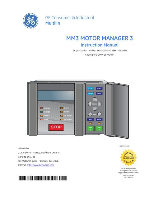
<strong>MM3</strong> <strong>MOTOR</strong> <strong>MANA<strong>GE</strong>R</strong> 3<br />
<strong>Instruction</strong> <strong>Manual</strong><br />
AUX RELAY 1<br />
AUX RELAY 2<br />
<strong>GE</strong> publication number: 1601-0107-A7 (<strong>GE</strong>K-106295F)<br />
Copyright © 2007 <strong>GE</strong> Multilin<br />
ACTUAL<br />
SETPOINT<br />
MESSA<strong>GE</strong><br />
VALUE<br />
STORE<br />
RESET<br />
AUTO MANUAL<br />
START<br />
A<br />
START<br />
B<br />
809773A1.CDR<br />
REGISTERED<br />
ISO9001:2000<br />
G E M U LT I L I N<br />
<strong>GE</strong> Multilin's Quality<br />
Management System is<br />
registered to ISO9001:2000<br />
QMI # 005094<br />
UL # A3775
© 2007 <strong>GE</strong> Multilin Incorporated. All rights reserved.<br />
<strong>GE</strong> Multilin <strong>MM3</strong> Motor Manager 3 instruction manual for revision 1.2x.<br />
<strong>MM3</strong> Motor Manager 3, EnerVista, EnerVista Launchpad, EnerVista <strong>MM3</strong> Setup, and FlexLogic are registered trademarks of<br />
<strong>GE</strong> Multilin Inc.<br />
The contents of this manual are the property of <strong>GE</strong> Multilin Inc. This documentation is furnished on license and may not be<br />
reproduced in whole or in part without the permission of <strong>GE</strong> Multilin. The content of this manual is for informational use<br />
only and is subject to change without notice.<br />
Part numbers contained in this manual are subject to change without notice, and should therefore be verified by <strong>GE</strong><br />
Multilin before ordering.<br />
Part number: 1601-0107-A7 (October 2007)
TABLE OF CONTENTS<br />
TABLE OF CONTENTS<br />
1: INTRODUCTION OVERVIEW ........................................................................................................................................... 1-1<br />
DESCRIPTION ........................................................................................................................ 1-1<br />
FEATURES ............................................................................................................................. 1-1<br />
ORDER CODES ...................................................................................................................... 1-5<br />
ACCESSORIES ....................................................................................................................... 1-5<br />
TECHNICAL SPECIFICATIONS ...................................................................................................... 1-6<br />
PROTECTION ......................................................................................................................... 1-6<br />
INPUTS .................................................................................................................................. 1-7<br />
OUTPUTS ...............................................................................................................................1-7<br />
COMMUNICATIONS .............................................................................................................. 1-8<br />
CONFORMANCE ................................................................................................................... 1-8<br />
2: INSTALLATION MOUNTING ......................................................................................................................................... 2-1<br />
DESCRIPTION ........................................................................................................................ 2-1<br />
WIRING ................................................................................................................................................. 2-2<br />
TYPICAL WIRING .................................................................................................................. 2-2<br />
INPUTS AND OUTPUTS .................................................................................................................. 2-3<br />
PHASE CT INPUTS ............................................................................................................... 2-3<br />
GROUND FAULT CT INPUT ................................................................................................ 2-3<br />
SUPPLY VOLTA<strong>GE</strong> ................................................................................................................ 2-3<br />
GROUND SUR<strong>GE</strong> .................................................................................................................. 2-3<br />
EXTERNAL CONNECTIONS .................................................................................................. 2-3<br />
THERMISTOR INPUT ............................................................................................................. 2-3<br />
ANALOG INPUT .................................................................................................................... 2-4<br />
ANALOG OUTPUT ................................................................................................................ 2-4<br />
AUXILIARY 2 COIL ............................................................................................................... 2-4<br />
OUTPUT RELAYS .................................................................................................................. 2-4<br />
SERIAL COMMUNICATION PORT ........................................................................................ 2-4<br />
SWITCH INPUTS ................................................................................................................... 2-5<br />
PROGRAMMABLE SWITCH INPUTS ..................................................................................... 2-5<br />
STOP ...................................................................................................................................... 2-5<br />
START A AND START B ....................................................................................................... 2-5<br />
LOCAL ISOLATOR NO ......................................................................................................... 2-6<br />
CONTACTOR STATUS ........................................................................................................... 2-6<br />
DIELECTRIC STRENGTH TESTING ....................................................................................... 2-6<br />
STARTER TYPES ................................................................................................................................. 2-7<br />
FULL-VOLTA<strong>GE</strong> NON-REVERSING STARTER ..................................................................... 2-7<br />
FULL-VOLTA<strong>GE</strong> REVERSING STARTER ............................................................................... 2-9<br />
TWO-SPEED STARTER ......................................................................................................... 2-11<br />
SLIP RING STARTER ............................................................................................................. 2-16<br />
PRIMARY RESISTANCE STARTER ......................................................................................... 2-18<br />
INVERTER STARTER .............................................................................................................. 2-20<br />
AUTOTRANSFORMER OPEN TRANSITION STARTER .......................................................... 2-21<br />
AUTOTRANSFORMER CLOSED TRANSITION STARTER ...................................................... 2-25<br />
PART WINDING STARTER ................................................................................................... 2-29<br />
WYE-DELTA OPEN TRANSITION STARTER ........................................................................ 2-30<br />
WYE-DELTA CLOSED TRANSITION STARTER .................................................................... 2-32<br />
<strong>MM3</strong> <strong>MOTOR</strong> <strong>MANA<strong>GE</strong>R</strong> 3 – INSTRUCTION MANUAL i
TABLE OF CONTENTS<br />
DUTY/STANDBY STARTER ................................................................................................... 2-34<br />
SOFT STARTER ...................................................................................................................... 2-36<br />
3: HARDWARE USER INTERFACE .............................................................................................................................. 3-1<br />
DESCRIPTION ........................................................................................................................ 3-1<br />
MESSA<strong>GE</strong> DISPLAY .............................................................................................................. 3-1<br />
INDICATOR LEDS ................................................................................................................. 3-2<br />
KEYPAD ................................................................................................................................................. 3-4<br />
SETPOINTS KEY .................................................................................................................... 3-4<br />
ACTUAL VALUES KEY .......................................................................................................... 3-4<br />
STORE KEY ............................................................................................................................ 3-4<br />
STOP KEY .............................................................................................................................. 3-5<br />
RESET KEY ............................................................................................................................ 3-5<br />
START A/B KEYS ................................................................................................................. 3-5<br />
MESSA<strong>GE</strong> UP/DOWN KEYS ................................................................................................ 3-5<br />
MESSA<strong>GE</strong> LEFT/RIGHT KEYS .............................................................................................. 3-5<br />
VALUE KEYS ......................................................................................................................... 3-5<br />
HARDWARE DESCRIPTION ...........................................................................................................3-6<br />
<strong>MM3</strong> <strong>MOTOR</strong> <strong>MANA<strong>GE</strong>R</strong> 3 DESIGN ................................................................................ 3-6<br />
4: SOFTWARE OVERVIEW ........................................................................................................................................... 4-1<br />
DESCRIPTION ........................................................................................................................ 4-1<br />
REQUIREMENTS .................................................................................................................... 4-2<br />
CHECKING IF INSTALLATION/UPGRADE IS REQUIRED ..................................................... 4-2<br />
INSTALLING ENERVISTA <strong>MM3</strong> SETUP .............................................................................. 4-2<br />
CONFIGURATION .............................................................................................................................. 4-5<br />
SERIAL COMMUNICATIONS ................................................................................................. 4-5<br />
ETHERNET COMMUNICATIONS ........................................................................................... 4-7<br />
USING ENERVISTA <strong>MM3</strong> SETUP ................................................................................................. 4-8<br />
SAVING SETPOINTS TO A FILE ............................................................................................ 4-8<br />
FIRMWARE UPGRADES ........................................................................................................ 4-9<br />
LOADING SETPOINT FILES .................................................................................................. 4-10<br />
ENTERING SETPOINTS ......................................................................................................... 4-11<br />
VIEWING ACTUAL VALUES .................................................................................................. 4-12<br />
CHASSIS MOUNT UNITS ................................................................................................................ 4-15<br />
DESCRIPTION ........................................................................................................................ 4-15<br />
SETTING THE BAUD RATE AND PARITY ............................................................................. 4-15<br />
5: SETPOINTS OVERVIEW ........................................................................................................................................... 5-1<br />
SETPOINTS MAIN MENU ..................................................................................................... 5-1<br />
DESCRIPTION ........................................................................................................................ 5-3<br />
SETPOINT MESSA<strong>GE</strong> ABBREVIATIONS ............................................................................... 5-4<br />
S1 CONFIGURATION ....................................................................................................................... 5-5<br />
COMMUNICATIONS .............................................................................................................. 5-5<br />
<strong>MOTOR</strong> IDENTIFICATION ..................................................................................................... 5-5<br />
STARTER ................................................................................................................................ 5-6<br />
CT/VT INPUTS ..................................................................................................................... 5-7<br />
THERMISTOR ......................................................................................................................... 5-8<br />
FAULT MODE ........................................................................................................................ 5-9<br />
STATISTICS ............................................................................................................................ 5-9<br />
PROGRAMMABLE MESSA<strong>GE</strong> ................................................................................................ 5-10<br />
ii <strong>MM3</strong> <strong>MOTOR</strong> <strong>MANA<strong>GE</strong>R</strong> 3 – INSTRUCTION MANUAL
TABLE OF CONTENTS<br />
PREFERENCES ....................................................................................................................... 5-10<br />
S2 PROTECTION ................................................................................................................................ 5-11<br />
<strong>MOTOR</strong> PROTECTION: THERMAL ........................................................................................ 5-11<br />
<strong>MOTOR</strong> PROTECTION: GROUND FAULT ............................................................................ 5-16<br />
<strong>MOTOR</strong> PROTECTION: OPTIONS ........................................................................................ 5-17<br />
LOAD PROTECTION .............................................................................................................. 5-19<br />
UNDER/OVERVOLTA<strong>GE</strong> PROTECTION ................................................................................ 5-21<br />
S3 PROCESS ....................................................................................................................................... 5-22<br />
PROGRAMMABLE INPUTS .................................................................................................... 5-22<br />
INTERLOCK NAMES .............................................................................................................. 5-27<br />
STOP CONFIGURATION ....................................................................................................... 5-27<br />
ANALOG INPUT .................................................................................................................... 5-28<br />
ANALOG OUTPUT ................................................................................................................ 5-29<br />
PROCESS OPTIONS .............................................................................................................. 5-30<br />
S4 CONTROL ...................................................................................................................................... 5-31<br />
UNDERVOLTA<strong>GE</strong> AUTO RESTART ....................................................................................... 5-31<br />
AUXILIARY RELAY CONFIGURATION .................................................................................. 5-32<br />
S5 MONITORING ............................................................................................................................... 5-35<br />
PLANT CONDITION .............................................................................................................. 5-35<br />
PRESET COUNTERS AND TIMERS ....................................................................................... 5-36<br />
S6 FACTORY DATA ........................................................................................................................... 5-37<br />
PRODUCT FIRMWARE IDENTIFICATION ............................................................................. 5-37<br />
PRODUCT MODEL IDENTIFICATION ................................................................................... 5-37<br />
FACTORY SERVICE DATA .................................................................................................... 5-37<br />
S7 TESTING ......................................................................................................................................... 5-38<br />
TEST CONFIGURATION ........................................................................................................ 5-38<br />
TEST RELAYS AND LEDS .................................................................................................... 5-38<br />
CURRENT SIMULATION ........................................................................................................ 5-39<br />
ANALOG OUTPUT SIMULATION ......................................................................................... 5-40<br />
ANALOG INPUT SIMULATION ............................................................................................. 5-41<br />
SWITCH INPUTS SIMULATION ............................................................................................ 5-41<br />
THERMISTOR SIMULATION .................................................................................................. 5-42<br />
6: ACTUAL VALUES OVERVIEW ........................................................................................................................................... 6-1<br />
ACTUAL VALUES MAIN MENU ........................................................................................... 6-1<br />
DEFAULT MESSA<strong>GE</strong> SELECTION ......................................................................................... 6-2<br />
ACTUAL VALUES ABBREVIATIONS ..................................................................................... 6-2<br />
A1 DATA ............................................................................................................................................... 6-3<br />
<strong>MOTOR</strong> DATA ....................................................................................................................... 6-3<br />
PROCESS DATA .................................................................................................................... 6-4<br />
PROGRAMMABLE MESSA<strong>GE</strong> ............................................................................................... 6-5<br />
A2 STATUS .......................................................................................................................................... 6-6<br />
TRIP DATA ............................................................................................................................ 6-6<br />
ALARM DATA ........................................................................................................................ 6-7<br />
<strong>MOTOR</strong> STATUS ................................................................................................................... 6-10<br />
A3 INPUTS ........................................................................................................................................... 6-12<br />
INPUT CONTACTS STATUS .................................................................................................. 6-12<br />
A4 STATISTICS ................................................................................................................................... 6-13<br />
TIMERS .................................................................................................................................. 6-13<br />
COUNTERS ............................................................................................................................ 6-13<br />
<strong>MM3</strong> <strong>MOTOR</strong> <strong>MANA<strong>GE</strong>R</strong> 3 – INSTRUCTION MANUAL iii
TABLE OF CONTENTS<br />
7: TESTING INJECTION TESTING ........................................................................................................................ 7-1<br />
PRIMARY INJECTION TESTING ............................................................................................ 7-1<br />
SECONDARY INJECTION TESTING ...................................................................................... 7-1<br />
FUNCTIONAL TESTS ........................................................................................................................ 7-3<br />
PHASE CURRENT FUNCTIONS ............................................................................................ 7-3<br />
UNBALANCE EXAMPLES ...................................................................................................... 7-4<br />
GROUND FAULT CURRENT FUNCTIONS ........................................................................... 7-5<br />
INPUT FUNCTIONS ............................................................................................................... 7-5<br />
THERMISTOR INPUT TESTS ................................................................................................. 7-5<br />
POWER FAIL TEST ................................................................................................................ 7-6<br />
8: COMMUNICATIONS <strong>MM3</strong> <strong>MOTOR</strong> <strong>MANA<strong>GE</strong>R</strong> 3 MODBUS PROTOCOL ............................................................... 8-1<br />
OVERVIEW ............................................................................................................................ 8-1<br />
ELECTRICAL INTERFACE ....................................................................................................... 8-1<br />
DATA FRAME FORMAT AND DATA RATE .......................................................................... 8-2<br />
DATA PACKET FORMAT ....................................................................................................... 8-2<br />
ERROR CHECKING ................................................................................................................ 8-3<br />
TIMING .................................................................................................................................. 8-4<br />
SUPPORTED MODBUS FUNCTIONS ......................................................................................... 8-5<br />
DESCRIPTION ........................................................................................................................ 8-5<br />
FUNCTION CODE 01H ........................................................................................................ 8-5<br />
FUNCTION CODE 03H ........................................................................................................ 8-6<br />
FUNCTION CODE 04H ........................................................................................................ 8-6<br />
FUNCTION CODE 05H ........................................................................................................ 8-7<br />
FUNCTION CODE 06H ........................................................................................................ 8-8<br />
FUNCTION CODE 07H ........................................................................................................ 8-8<br />
FUNCTION CODE 08H ........................................................................................................ 8-10<br />
FUNCTION CODE 10H ........................................................................................................ 8-10<br />
ERROR RESPONSES .............................................................................................................. 8-11<br />
APPLICATIONS ................................................................................................................................... 8-12<br />
PERFORMING COMMANDS USING FUNCTION CODE 10H ............................................. 8-12<br />
STORING ADDRESSES USING THE BROADCAST COMMAND ........................................... 8-12<br />
USING THE USER-DEFINABLE MEMORY MAP .................................................................. 8-13<br />
MODBUS MEMORY MAP ................................................................................................................ 8-16<br />
DESCRIPTION ........................................................................................................................ 8-16<br />
MODBUS DATA FORMATS .................................................................................................. 8-43<br />
9: APPLICATIONS CONTROL WIRE APPLICATIONS ................................................................................................. 9-1<br />
TWO-WIRE CONTROL .......................................................................................................... 9-1<br />
HOA TWO-WIRE HAND / TWO-WIRE AUTO .................................................................. 9-2<br />
HOA THREE-WIRE HAND / TWO-WIRE AUTO ................................................................ 9-4<br />
HOA THREE-WIRE HAND / THREE-WIRE AUTO ............................................................ 9-5<br />
HA THREE-WIRE HAND / TWO-WIRE AUTO ................................................................... 9-6<br />
10: MISCELLANEOUS ASYMMETRICAL STARTING CURRENT ..................................................................................... 10-1<br />
OVERVIEW ............................................................................................................................ 10-1<br />
CT ISOLATION .................................................................................................................................... 10-4<br />
<strong>MM3</strong> <strong>MOTOR</strong> <strong>MANA<strong>GE</strong>R</strong> 3 CT WITHSTAND .................................................................. 10-4<br />
CT SIZE AND SATURATION ................................................................................................. 10-4<br />
<strong>MM3</strong> <strong>MOTOR</strong> <strong>MANA<strong>GE</strong>R</strong> 3 FAQ .................................................................................................. 10-7<br />
iv <strong>MM3</strong> <strong>MOTOR</strong> <strong>MANA<strong>GE</strong>R</strong> 3 – INSTRUCTION MANUAL
INDEX<br />
TABLE OF CONTENTS<br />
FREQUENTLY ASKED QUESTIONS ...................................................................................... 10-7<br />
INSTALLATION CHECKLIST ........................................................................................................... 10-9<br />
OVERVIEW ............................................................................................................................ 10-9<br />
<strong>MM3</strong> <strong>MOTOR</strong> <strong>MANA<strong>GE</strong>R</strong> 3 GROUNDING ........................................................................ 10-9<br />
GROUNDING OF PHASE AND GROUND CTS .................................................................... 10-9<br />
RS485 COMMUNICATIONS PORT ..................................................................................... 10-9<br />
SWITCH INPUTS ................................................................................................................... 10-10<br />
THERMISTOR AND ANALOG INPUTS .................................................................................. 10-10<br />
STOP SWITCH INPUT ........................................................................................................... 10-10<br />
CONTACTOR STATUS FEEDBACK ....................................................................................... 10-10<br />
EU DECLARATION OF CONFORMITY ........................................................................................ 10-11<br />
EU DECLARATION ............................................................................................................... 10-11<br />
CHAN<strong>GE</strong> NOTES ................................................................................................................................ 10-12<br />
REVISION HISTORY .............................................................................................................. 10-12<br />
CHAN<strong>GE</strong>S TO THE <strong>MM3</strong> <strong>MOTOR</strong> <strong>MANA<strong>GE</strong>R</strong> 3 MANUAL .............................................. 10-12<br />
<strong>GE</strong> MULTILIN WARRANTY ............................................................................................................. 10-13<br />
WARRANTY STATEMENT ..................................................................................................... 10-13<br />
<strong>MM3</strong> <strong>MOTOR</strong> <strong>MANA<strong>GE</strong>R</strong> 3 – INSTRUCTION MANUAL v
TABLE OF CONTENTS<br />
vi <strong>MM3</strong> <strong>MOTOR</strong> <strong>MANA<strong>GE</strong>R</strong> 3 – INSTRUCTION MANUAL
RUNNING<br />
STOPPED<br />
TRIPPED<br />
ALARM<br />
STOP<br />
RELAY A<br />
RELAY B<br />
AUX RELAY 1<br />
AUX RELAY 2<br />
<strong>GE</strong> Consumer & Industrial<br />
Multilin<br />
ACTUAL<br />
SETPOINT<br />
MESSA<strong>GE</strong><br />
VALUE<br />
STORE<br />
RESET<br />
AUTO MANUAL<br />
START<br />
A<br />
START<br />
B<br />
Introduction<br />
<strong>MM3</strong> Motor Manager 3<br />
Chapter 1: Introduction<br />
1.1 Overview<br />
1.1.1 Description The <strong>MM3</strong> Motor Manager 3 combines control functions normally found in a low voltage<br />
motor control center (MCC) with motor protection. This compact, microprocessor based<br />
device, provides sophisticated control and protective relaying at significant cost savings<br />
over an MCC design using discrete devices.<br />
Standard features simplify maintenance and plant expansion. One <strong>MM3</strong> Motor Manager 3<br />
is required for every starter unit in the MCC. The contactor can be energized and deenergized<br />
using the <strong>MM3</strong> Motor Manager 3's direct-wired inputs or via the serial port. Full<br />
voltage non-reversing, full voltage Reversing, two-speed, autotransformer, inverter, wyedelta,<br />
slip ring, and part winding type starters may be completely controlled by the <strong>MM3</strong><br />
Motor Manager 3 using the two contactor outputs.<br />
Motor protection is included for the most common causes of failure to prevent costly<br />
shutdowns and rewinds. These include three-phase overload, stalled rotor, ground fault<br />
and loss of phase.<br />
A two-wire RS485 Modbus communications port is provided for high speed<br />
communications with a complete line-up of MCCs. Any <strong>MM3</strong> Motor Manager 3 may be<br />
interrogated on demand to determine both actual and setpoint operating parameters.<br />
Fast response time to a request for alarm or trip status makes real time control of a<br />
complete process possible. Statistical recording of running hours and number of starts and<br />
trips assists with predictive maintenance scheduling.<br />
1.1.2 Features The <strong>MM3</strong> Motor Manager 3 has been developed with economy in mind. The customer is<br />
able to choose from different options to achieve maximum benefit from the relay when<br />
integrated into the process environment. The standard <strong>MM3</strong> Motor Manager 3 comes with<br />
<strong>MM3</strong> <strong>MOTOR</strong> <strong>MANA<strong>GE</strong>R</strong> 3 – INSTRUCTION MANUAL 1–1
OVERVIEW CHAPTER 1: INTRODUCTION<br />
three-phase overload protection (49/51), single-phase, four (4) control inputs (start, stop,<br />
local isolator, contactor A status) plus 4 programmable inputs. The full version adds the<br />
following additional features:<br />
• Second contactor control (wye/delta, two speed, reversing, etc.) including all<br />
timers, relays and control inputs<br />
• Undercurrent/underpower protection (ANSI 37)<br />
• Thermistor (ANSI 49) input which accepts PTC and NTC thermistor types<br />
• Analog input/output<br />
• Six (6) additional programmable inputs plus two (2) control inputs<br />
Table 1–1: <strong>MM3</strong> Motor Manager 3 Options<br />
Option 1 (standard) Option 2 (full)<br />
Contactor A Contactor A<br />
Serial communications Serial communications<br />
Four (4) programmable inputs Ten (10) programmable inputs<br />
Four (4) control inputs Six (6) control inputs<br />
Three (3) phase inputs Three (3) phase inputs<br />
One (1) ground fault input One (1) ground fault input<br />
Auxiliary 1 relay Aux 1 relay<br />
Auxiliary 2 / ESD relay Contactor B<br />
VT input Auxiliary 2 / ESD relay<br />
VT input<br />
Thermistor input<br />
Analog input<br />
Analog output<br />
1–2 <strong>MM3</strong> <strong>MOTOR</strong> <strong>MANA<strong>GE</strong>R</strong> 3 – INSTRUCTION MANUAL
CHAPTER 1: INTRODUCTION OVERVIEW<br />
Figure 1-1: Functional block diagram<br />
<strong>MM3</strong> <strong>MOTOR</strong> <strong>MANA<strong>GE</strong>R</strong> 3 – INSTRUCTION MANUAL 1–3
OVERVIEW CHAPTER 1: INTRODUCTION<br />
STATUS INDICATORS:<br />
RUNNING:Contactor is energized<br />
and motor is running.<br />
STOPPED: Contactor is not<br />
energized and motor is not running.<br />
TRIPPED: Contactor is not<br />
energized. Motor is not running.<br />
The <strong>MM3</strong> has tripped the motor due<br />
To a fault. Normally a cause of<br />
trip message will be displayed.<br />
ALARM: One or more alarm<br />
conditions are present.<br />
Normally a cause of alarm<br />
message will be displayed.<br />
DISPLAY:<br />
2 line, 40 character illuminated display<br />
communicates all messages in simple<br />
English for easy interpretation by users<br />
unfamiliar with unit.<br />
SWITCH INPUTS<br />
Opto-isolated 120/240 VAC live inputs for various interlock functions.<br />
The interlock inputs are fully programmable and can be assigned to<br />
functions as setpoint access, plant interlock, test, and various others.<br />
ANALOG INPUT/OUTPUT<br />
4 to 20mA input for<br />
Process control monitoring<br />
/ alarming / tripping.<br />
COMMUNICATIONS<br />
RS485 2 wire serial<br />
communication port<br />
operates at 1200 to<br />
57600 bps for remote<br />
commands, monitoring<br />
and setpoint store.<br />
Modbus ® RTU protocol.<br />
Front View<br />
Rear View<br />
THERMISTOR<br />
NTC or PTC thermistor<br />
input for hot winding<br />
detection.<br />
RESIDUAL GROUND INPUT<br />
PHASE CT INPUTS<br />
3 isolated phase CT inputs<br />
RELAY INDICATORS:<br />
RELAY A: Contactor A energized.<br />
RELAY B: Contactor B energized.<br />
AUX 1: User programmable relay 1 energized.<br />
AUX 2: User programmable relay 2 energized.<br />
GROUND CT INPUT<br />
50:0.025 ground fault<br />
input.<br />
Figure 1-2: Features<br />
PROGRAM KEYS:<br />
ACTUAL VALUES: Press to enter<br />
actual values mode to display actual<br />
Motor values such as current,<br />
ground leakage, thermal capacity.<br />
SETPOINTS:Press to enter setpoint<br />
mode to alter or examine setpoints.<br />
STORE: Save a newly entered<br />
setpoint.<br />
RESET:Reset the <strong>MM3</strong> after a trip.<br />
MESSA<strong>GE</strong>: Move to the desired<br />
setpoint or actual value message.<br />
VALUE: Increment or decrement<br />
currently displayed setpoint value.<br />
CONTROL KEYS:<br />
AUTO: Selects operation of start<br />
via communication port.<br />
MANUAL: Selects manual.<br />
operation of motor using the<br />
Start key.<br />
START A: Energize contactor A.<br />
START B: Energize contactor B.<br />
STOP: De-energize contactors.<br />
SUPPLY VOLTA<strong>GE</strong><br />
required to power the <strong>MM3</strong><br />
VOLTA<strong>GE</strong> INPUT<br />
Phase A voltage input for<br />
voltage and power monitoring.<br />
1–4 <strong>MM3</strong> <strong>MOTOR</strong> <strong>MANA<strong>GE</strong>R</strong> 3 – INSTRUCTION MANUAL<br />
Ground<br />
safety and<br />
surge<br />
CONTROL POWER<br />
120/240 VAC supply voltage<br />
selector switch and fuse<br />
access door<br />
4 RELAYS<br />
Contactor A: direct on<br />
line / forward / wye<br />
Contactor B: reverse / delta<br />
User programmable relay<br />
(AUX 1)<br />
User programmable relay<br />
(AUX 2)<br />
Ground safety<br />
809700A1.CDR<br />
10
CHAPTER 1: INTRODUCTION OVERVIEW<br />
1.1.3 Order codes The order codes for the <strong>MM3</strong> Motor Manager 3 are shown below.<br />
NOTE<br />
<strong>MM3</strong><br />
Motor<br />
Manag<br />
er 3<br />
Base unit <strong>MM3</strong><br />
Motor<br />
Manag<br />
er 3<br />
<strong>MM3</strong> Motor<br />
Manager 3<br />
options<br />
Table 1–2: Selection guide<br />
– – – – <br />
| | | | Product family<br />
1 | | | Option 1: basic unit<br />
2 | | | Option 2: full unit<br />
Relay E | | ESD relay<br />
A | | Auxiliary 2 relay<br />
Display N | No display (chassis unit)<br />
W | With local display<br />
Power 120 120 V AC control voltage<br />
240 240 V AC control voltage<br />
This instruction manual describes the features of a <strong>MM3</strong> Motor Manager 3 with all options<br />
included.<br />
Examples:<br />
• <strong>MM3</strong> Motor Manager 3–2–E–N–120: full-featured <strong>MM3</strong> Motor Manager 3, ESD<br />
relay, chassis mount unit with 120 V AC control power<br />
• <strong>MM3</strong> Motor Manager 3–1–A–W–240: basic <strong>MM3</strong> Motor Manager 3 with auxiliary 2<br />
relay, local display and 240 V AC control power<br />
1.1.4 Accessories The following accessories are available for the <strong>MM3</strong> Motor Manager 3:<br />
• EnerVista <strong>MM3</strong> Setup software: no-charge software package to aid in setting up<br />
<strong>MM3</strong> Motor Manager 3 operating parameters (available online at http://<br />
www.<strong>GE</strong>multilin.com)<br />
• RS-232/485: RS232 to RS485 converter box designed for harsh industrial<br />
environments<br />
• 5A Phase CT: 300, 350, 400, 500, 600, 750, 1000<br />
• 50:0.025 ground CT: For sensitive ground detection on high resistance grounded<br />
systems<br />
• Control key cover: Covers the auto/manual LEDs, keys and keypad start buttons<br />
<strong>MM3</strong> <strong>MOTOR</strong> <strong>MANA<strong>GE</strong>R</strong> 3 – INSTRUCTION MANUAL 1–5
TECHNICAL SPECIFICATIONS CHAPTER 1: INTRODUCTION<br />
NOTE<br />
1.2 Technical specifications<br />
Design and specifications subject to change without notice.<br />
1.2.1 Protection ACCELERATION TIME<br />
Range:......................................0.5 to 125 seconds or OFF<br />
Accuracy:................................± 0.5 seconds<br />
GROUND FAULT TRIP TIME<br />
Accuracy:................................–0 ms/+50 ms; 0.0 = less than 50 ms<br />
OVERLOAD CURVES TRIP TIME<br />
Accuracy:................................± 200 ms up to 10 seconds<br />
± 2% of trip time over 10 seconds<br />
Detection level: ....................± 1% of primary CT amps<br />
SINGLE PHASE<br />
Range:......................................greater than 30% U/B<br />
Accuracy:................................± 2 percentage points<br />
Trip delay:...............................5 seconds, ±1 second<br />
IM – IAV Calculation method: ......... if IAV ≥ : UB% = -------------------- × 100<br />
I FLC<br />
STALLED ROTOR<br />
Range:......................................1.15 to 4.50 × FLC or OFF<br />
Delay range:..........................0.5 to 5 seconds<br />
Accuracy:................................± 0.5 second<br />
THERMAL COOLING<br />
Range: .....................................5 to 1080 minutes when motor stopped<br />
50% of motor stopped value when motor running.<br />
Accuracy: ...............................± 1 minute<br />
UNDERCURRENT<br />
Range:......................................10 to 100% × motor FLC or OFF<br />
Delay range:..........................1 to 60 seconds<br />
Accuracy:................................±1 second<br />
UNDERVOLTA<strong>GE</strong><br />
Undervoltage:.......................65% of nominal (120 or 240 V AC);<br />
immediate restart for maximum dip time of 0.1 to 0.5 seconds or OFF;<br />
delayed restart for maximum dip time of 0.1 or 10.0 seconds or unlimited<br />
Delay restart range: ..........0.2 to 300 seconds<br />
Delay restart accuracy: ...±0.2 seconds<br />
1–6 <strong>MM3</strong> <strong>MOTOR</strong> <strong>MANA<strong>GE</strong>R</strong> 3 – INSTRUCTION MANUAL<br />
I AV<br />
IM – IAV if IAV < IFLC: UB% =<br />
-------------------- × 100<br />
IFLC where IAV = average phase current, IM = current in a phase with maximum<br />
deviation from IAV, and IFLC = motor full load current setting
CHAPTER 1: INTRODUCTION TECHNICAL SPECIFICATIONS<br />
1.2.2 Inputs ANALOG INPUT<br />
Range: ......................................4 to 20 mA<br />
Accuracy:................................±1% of full scale<br />
Alarm: .......................................programmable 4 to 20 mA<br />
Trip:............................................programmable 4 to 20 mA<br />
Isolation:..................................15 V isolated, active source<br />
GROUND FAULT CURRENT INPUT<br />
Conversion:............................true RMS, sample time 1.67 ms<br />
Range: ......................................0.1 to 1.0 × FLC amps setpoint (for residual connection)<br />
0.5 to 15.0 A (for 50:0.025 CT)<br />
Full scale: ................................1.5 × FLC amps setpoint (for residual connection)<br />
15 A (for 50:0.025 CT)<br />
Accuracy:................................± (2% + 2), for FLC < 32 A † (residual connection)<br />
± (2% + 6), for FLC ≥ 32 A † (residual connection)<br />
± 0.3 A (for 50:0.025 CT)<br />
† Accuracy given as ± ([% of reading] + [number of least significant digits])<br />
PHASE CURRENT INPUTS<br />
Conversion:...................... true RMS, sample time 1.67 ms<br />
Range: ......................................0.1 to 8 × PHASE CT PRIMARY AMPS setpoint when external CTs used<br />
0.2 to 250 A when FLC < 32 A<br />
1 to 2000 A when FLC ≥ 32 A<br />
Accuracy: ...............................± (2% +1) †<br />
Frequency: .............................20Hz - 200Hz sine wave<br />
SUPPLY VOLTA<strong>GE</strong><br />
AC nominal:............................115 V AC, range 80 to 135 V AC<br />
230 V AC, range 150 to 250 V AC<br />
Frequency: .............................50/60 Hz<br />
Power: ......................................25 VA (maximum), 7 VA (nominal)<br />
THERMISTOR INPUTS<br />
Sensor types:.........................positive temperature coefficient (PTC) R HOT = 100 to 30000 Ω;<br />
negative temperature coefficient (NTC) R HOT = 100 to 30000 Ω<br />
Delay:........................................1 second<br />
Accuracy:................................± 5% or 100 Ω (whichever is greater)<br />
VOLTA<strong>GE</strong> INPUT / POWER READING<br />
Conversion:............................true RMS, sample time 1.67 ms<br />
Voltage full scale:................1.5 × VT primary<br />
Voltage accuracy:...............± 2% of VT primary or 2% of reading, whichever is greater<br />
Power accuracy:..................± 5% of nominal or ± 5% of reading, whichever is greater<br />
Input voltage:........................120 V AC or 240 V AC nominal;<br />
250 V AC maximum<br />
VT burden: ..............................0.01 VA<br />
1.2.3 Outputs ANALOG OUTPUTS<br />
Output:.....................................4 to 20 mA<br />
Maximum load: ....................600 Ω<br />
Maximum output: ...............21 mA<br />
Accuracy:................................±1% of full scale reading<br />
Isolation:..................................36 V isolated, active source<br />
<strong>MM3</strong> <strong>MOTOR</strong> <strong>MANA<strong>GE</strong>R</strong> 3 – INSTRUCTION MANUAL 1–7
TECHNICAL SPECIFICATIONS CHAPTER 1: INTRODUCTION<br />
CONTACTOR A AND B OUTPUT RELAYS<br />
Operating current:..............8 A maximum<br />
Operating voltage: .............380 V AC / 125 V DC maximum<br />
Make/carry: ...........................8 A continuous at 30 V DC / 250 V AC (resistive loads)<br />
3.5 A continuous at 30 V DC / 250 V AC (inductive loads, PF = 0.4)<br />
Switching capacity: ...........2500 VA / 300 W maximum at 30 V DC / 250 V AC (resistive loads)<br />
1250 VA / 220 W maximum at 30 V DC / 250 V AC (inductive loads, PF = 0.4)<br />
Configuration: ......................SPST-NO, form-A<br />
Contact material:................silver alloy (AgCdO)<br />
Minimum permissible load: 5 V DC, 10 mA minimum<br />
AUXILIARY 1 AND 2 OUTPUT RELAYS<br />
Operating current:..............8 A maximum<br />
Operating voltage: .............380 V AC / 125 V DC maximum<br />
Make/carry: ...........................8 A continuous at 30 V DC / 250 V AC (resistive loads)<br />
3.5 A continuous at 30 V DC / 250 V AC (inductive loads, PF = 0.4)<br />
Switching capacity: ...........2000 VA / 240 W maximum at 30 V DC / 250 V AC (resistive loads)<br />
875 VA / 170 W maximum at 30 V DC / 250 V AC (inductive loads, PF = 0.4)<br />
Configuration: ......................SPST-NO + SPST-NC, form-C<br />
Contact material:................silver alloy (AgCdO)<br />
Minimum permissible load: 5 V DC, 10 mA minimum<br />
1.2.4 Communications PORTS<br />
Type: ........................................RS485 2-wire, half duplex<br />
Baud rate: .............................1200 bps to 57 kbps<br />
Protocol: .................................Modbus RTU<br />
Functions: ..............................read/write setpoints, read coil status, read actual values, read device status,<br />
execute commands, loopback test<br />
1.2.5 Conformance TYPE TESTS<br />
Transients:..............................ANSI/IEEE C37.90.1 Oscillatory/Fast Risetime Transients<br />
IEC 801-4 Electrical Fast Transient/Burst Requirements<br />
Impulse: ..................................IEC 255-5 5 kV Impulse Voltage Test<br />
RFI: ............................................150 MHz, 450 MHz 5W Handheld Transmitter at 25 cm<br />
Static: ......................................IEC 801-2 Electrostatic Discharge<br />
HIPOT: ......................................60255.5 Dielectric Strength: 2.3kV AC for 1 minute<br />
PRODUCTION TEST<br />
HIPOT: ......................................2.1kV AC for 1 second<br />
CERTIFICATION/COMPLIANCE<br />
UL:..............................................UL Listed (File E83849)<br />
UL 508 - Industrial Control Equipment<br />
UL 1053 - Ground Fault Protection Equipment<br />
CSA:...........................................Certified per C22.2 No. 14 - Industrial Control Equipment<br />
CE:..............................................IEC 947-1, IEC 1010-1<br />
ISO: ............................................registered to ISO 9001-1994<br />
ENVIRONMENT<br />
Pollution degree: .................2<br />
1–8 <strong>MM3</strong> <strong>MOTOR</strong> <strong>MANA<strong>GE</strong>R</strong> 3 – INSTRUCTION MANUAL
CHAPTER 1: INTRODUCTION TECHNICAL SPECIFICATIONS<br />
CAUTION<br />
NOTE<br />
OPERATION<br />
Overvoltage category:......2<br />
Insulation voltage:..............300 V<br />
OPERATING TEMPERATURES<br />
Cold: ..........................................IEC60068-2-1, 16h at -40°C<br />
Dry Heat:.................................IEC60068-2-2, 16h at +85°C<br />
HUMIDITY (NON CONDENSING)<br />
.....................................................IEC60068-2-30, 95% variant 1, 6 days<br />
IP class: ....................................IEC 529 – IpX0<br />
Fuse:..........................................0.5 A, 250 V fast blow, high breaking capacity<br />
DIMENSIONS<br />
Weight: ...................................6 lbs. 12 oz. (3.1 kg) maximum<br />
Shipping box:................... 12" × 9" × 7.5" (350 mm × 229 mm × 190 mm)<br />
INSTALLATION<br />
Ventilation requirements:None<br />
Cleaning requirements: None<br />
HAZARD may result if the product is not used for its intended purpose.<br />
It is recommended that all <strong>MM3</strong> Motor Manager 3 relays are powered up at least once per<br />
year to avoid deterioration of electrolytic capacitors in the power supply.<br />
<strong>MM3</strong> <strong>MOTOR</strong> <strong>MANA<strong>GE</strong>R</strong> 3 – INSTRUCTION MANUAL 1–9
TECHNICAL SPECIFICATIONS CHAPTER 1: INTRODUCTION<br />
1–10 <strong>MM3</strong> <strong>MOTOR</strong> <strong>MANA<strong>GE</strong>R</strong> 3 – INSTRUCTION MANUAL
RUNNING<br />
STOPPED<br />
TRIPPED<br />
ALARM<br />
STOP<br />
RELAY A<br />
RELAY B<br />
AUX RELAY 1<br />
AUX RELAY 2<br />
<strong>GE</strong> Consumer & Industrial<br />
Multilin<br />
ACTUAL<br />
SETPOINT<br />
MESSA<strong>GE</strong><br />
VALUE<br />
STORE<br />
RESET<br />
AUTO MANUAL<br />
START<br />
A<br />
START<br />
B<br />
Installation<br />
<strong>MM3</strong> Motor Manager 3<br />
Chapter 2: Installation<br />
2.1 Mounting<br />
2.1.1 Description Cut the panel as shown below to mount the <strong>MM3</strong> Motor Manager 3. Use either the #8-32 or<br />
#6 × 1/2” mounting screws provided to mount the <strong>MM3</strong> Motor Manager 3 to the panel.<br />
Figure 2-1: <strong>MM3</strong> Motor Manager 3 Dimensions<br />
<strong>MM3</strong> <strong>MOTOR</strong> <strong>MANA<strong>GE</strong>R</strong> 3 – INSTRUCTION MANUAL 2–1
WIRING CHAPTER 2: INSTALLATION<br />
2.2 Wiring<br />
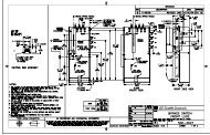
2.2.1 Typical Wiring A typical wiring diagram for the <strong>MM3</strong> Motor Manager 3 is shown below. The purpose of this<br />
diagram is to provide an example of how the <strong>MM3</strong> Motor Manager 3 is typically wired, not<br />
specifically how to wire the <strong>MM3</strong> Motor Manager 3. Please refer to the following pages for<br />
details on wiring the unit based on general requirements.<br />
Figure 2-2: Typical Wiring Diagram<br />
2–2 <strong>MM3</strong> <strong>MOTOR</strong> <strong>MANA<strong>GE</strong>R</strong> 3 – INSTRUCTION MANUAL
CHAPTER 2: INSTALLATION INPUTS AND OUTPUTS<br />
2.3.1 Phase CT<br />
Inputs<br />
2.3.2 Ground Fault<br />
CT Input<br />
2.3 Inputs and Outputs<br />
For motor full-load currents up to 250 A, the phase conductors can be directly connected<br />
to the <strong>MM3</strong> Motor Manager 3 without phase CTs. If external CTs are required, the<br />
secondary winding should be looped though the <strong>MM3</strong> Motor Manager 3 doughnut<br />
opening.<br />
Selected CTs should be capable of supplying the required current to the total secondary<br />
load which consists of the connection wiring burden. The CT must not saturate under<br />
maximum current conditions which can be up to 8 times motor full load during starting.<br />
The ground fault detection consists of a 50:0.025 input (terminal 19) and a common input<br />
(terminal 20), or residual connection of phase CTs (only the common input should be<br />
externally grounded). Residual ground fault protection provides a sensitivity of 10% of<br />
motor full load current. The 50:0.025 core balance (zero-sequence) CT input can be used<br />
for improved sensitivity when measuring the ground fault current.<br />
Care must be taken when enabling the ground fault trip feature. If the interrupting device<br />
(contactor or circuit breaker) is not rated to break ground fault current (low resistance or<br />
solidly grounded systems), the feature should be disabled. The 50:0.025 input is only<br />
recommended to be used on resistance grounded systems.<br />
2.3.3 Supply Voltage A supply voltage of 120/240 V AC at 50/60 Hz is required to power the <strong>MM3</strong> Motor<br />
Manager 3. The label on the back of the unit specifies the voltage that has been internally<br />
set. To change the voltage setting, open the sliding door on the back of the <strong>MM3</strong> Motor<br />
Manager 3 and locate the supply voltage selector slide switch. The selector slide switch<br />
has a label affixed to show the 120/240 V AC positions. Set the slide switch to the desired<br />
voltage.<br />
2.3.4 Ground Surge This is an additional ground terminal provided for dissipating transient signals and surges.<br />
This must be connected by a thick wire or braid to the system ground for reliable<br />
operation.<br />
2.3.5 External<br />
Connections<br />
2.3.6 Thermistor<br />
Input<br />
NOTE<br />
Signal wiring is to box terminals that can accommodate wire as large as 12 gauge. Consult<br />
Figure 2-2: Typical Wiring Diagram on page 2–2. Other features can be wired as required.<br />
Either a positive temperature coefficient (PTC) or negative temperature coefficient (NTC)<br />
thermistor may be directly connected to the <strong>MM3</strong> Motor Manager 3. By specifying the hot<br />
and cold thermistor resistance, the <strong>MM3</strong> Motor Manager 3 automatically determines the<br />
thermistor type as NTC or PTC. Use thermistors with hot and cold resistance values in the<br />
range 100 to 30000 Ω. If no thermistor is connected, the S1 CONFIGURATION <br />
THERMISTOR THERMISTOR TRIP and S1 CONFIGURATION THERMISTOR <br />
THERMISTOR ALARM setpoints must be set to “Disable”.<br />
<strong>MM3</strong> <strong>MOTOR</strong> <strong>MANA<strong>GE</strong>R</strong> 3 – INSTRUCTION MANUAL 2–3
INPUTS AND OUTPUTS CHAPTER 2: INSTALLATION<br />
2.3.7 Analog Input The <strong>MM3</strong> Motor Manager 3 accepts an analog input from a standard 4 to 20 mA source.<br />
This input can be used for process control monitoring to provide status and/or alarm and<br />
tripping signals related to the input signal level. The analog input messages (S3 PROCESS<br />
ANALOG INPUT setpoints page) can be programmed to show user-defined names<br />
and units.<br />
2.3.8 Analog Output The <strong>MM3</strong> Motor Manager 3 is available with a single analog current output for one<br />
parameter. The choice of output is selected with the S3 PROCESS ANALOG OUTPUT <br />
ANALOG OUTPUT TYPE setpoint. The analog output current scale is 4 to 20 mA.<br />
2.3.9 Auxiliary 2 Coil The AUX 2 relay can be internally energized by the <strong>MM3</strong> Motor Manager 3 or externally<br />
energized by applying a +24 V DC signal to these terminals. Correct polarity is required<br />
(terminal 35 = +24 V DC, terminal 34 = 0 V DC).<br />
2.3.10 Output Relays There are up to four (4) output relays on the <strong>MM3</strong> Motor Manager 3. Contact switching<br />
rating for the output relays as well can be found in Technical specifications on page 1–6.<br />
2.3.11 Serial Communication<br />
Port<br />
• Contactor A relay (terminals 46 and 47): non-reversing, forward, low speed, etc.<br />
• Contactor B relay (terminals 44 and 45): reversing, high speed, etc.<br />
• AUX 1 relay (terminals 40 to 43): field programmable<br />
• AUX 2 relay (terminals 36 to 39): field programmable or hard-wired 24 V DC coil<br />
A serial port provides communication capabilities to the <strong>MM3</strong> Motor Manager 3. Multiple<br />
<strong>MM3</strong> Motor Manager 3 relays can be connected together with a 24 AWG stranded,<br />
shielded twisted-pair with a characteristic impedance of 120 Ω such as Belden 9841 or<br />
equivalent. The total length of communications wiring should not exceed 4000 feet. Care<br />
should be used when routing the communications wiring to avoid power AC lines and<br />
other sources of electrical noise.<br />
Correct polarity is essential for the communications port to operate. Terminal 25 (“+”) of<br />
every <strong>MM3</strong> Motor Manager 3 in a serial communication link must be connected together.<br />
Similarly, terminal 26 (“–”) of every <strong>MM3</strong> Motor Manager 3 must also be connected<br />
together. The shield wire must be connected to terminal 27 (485 serial ground) on every<br />
unit in the link to provide a common ground potential for all units. Each relay should be<br />
daisy-chained to the next one. Avoid star or stub connected configurations if possible to<br />
avoid potential communication problems.<br />
A terminating resistor and capacitor network is required to prevent communication errors.<br />
Only the last <strong>MM3</strong> Motor Manager 3 and the master computer driver should have the<br />
terminating network to ensure proper matching. Using terminating resistors and<br />
capacitors on all the <strong>MM3</strong> Motor Manager 3s would load down the communication<br />
network while omitting them at the ends could cause reflections resulting in<br />
communication errors.<br />
2–4 <strong>MM3</strong> <strong>MOTOR</strong> <strong>MANA<strong>GE</strong>R</strong> 3 – INSTRUCTION MANUAL
CHAPTER 2: INSTALLATION INPUTS AND OUTPUTS<br />
Figure 2-3: RS485 termination<br />
2.3.12 Switch Inputs All switch inputs are opto-isolated and operate at 120 V AC. The switch reads closed when<br />
120 V AC is applied to the switch terminal. This 120 V AC can be supplied by an external<br />
source providing that the source is in phase with the <strong>MM3</strong> Motor Manager 3 supply<br />
voltage. When the <strong>MM3</strong> Motor Manager 3 control voltage switch is set to 240 V AC, the<br />
switch circuit also operates at 240 V AC.<br />
2.3.13 Programmable<br />
Switch Inputs<br />
These 10 inputs can be programmed to one of a number of different functions. Some of the<br />
available functions are: setpoint access, lockout reset, plant interlock, auto start, remote<br />
permissive, and test. See the S3 PROCESS PROGRAMMABLE INPUTS setpoints page for<br />
complete list of available functions.<br />
2.3.14 Stop If this terminal is de-energized, both contactor A and contactor B output relays will open<br />
causing the contactor coils to de-energize. The stop input must be energized before the<br />
<strong>MM3</strong> Motor Manager 3 will process any start commands.<br />
2.3.15 Start A and<br />
Start B<br />
When the start input terminals are energized, the corresponding contactor output relay is<br />
energized provided all other valid start conditions are met. If any trip occurs, both<br />
contactor outputs become de-energized. The start A input is used for all types of<br />
contactors, that is: full voltage non-reversing, two-speed (low-speed), reversing, wye delta<br />
open transition, inverter, slip ring, autotransformer, part winding, or wye delta closed<br />
transition. The start B input is used for reversing and two-speed (high-speed) contactor<br />
control. Start inputs are usually momentary unless two-wire control is used. Start A and B<br />
commands may also be initiated via the serial link.<br />
<strong>MM3</strong> <strong>MOTOR</strong> <strong>MANA<strong>GE</strong>R</strong> 3 – INSTRUCTION MANUAL 2–5
INPUTS AND OUTPUTS CHAPTER 2: INSTALLATION<br />
2.3.16 Local Isolator<br />
NO<br />
2.3.17 Contactor<br />
Status<br />
2.3.18 Dielectric<br />
Strength<br />
Testing<br />
CAUTION<br />
The local isolator NO auxiliary contacts are used to prevent motor starts in the event of the<br />
local isolator being in the “open” position. To prevent starts, the <strong>MM3</strong> Motor Manager 3<br />
produces a trip when the local isolator input is open. A local isolator trip is automatically<br />
reset when the local isolator is reclosed.<br />
The local isolator input can be enabled or disabled as required. The factory default is<br />
disabled.<br />
The <strong>MM3</strong> Motor Manager 3 must know the state of the contactor at all times in order to<br />
detect discrepancies in contactor close/open commands and also to display the state of<br />
the contactor. There are two contactor status inputs on the <strong>MM3</strong> Motor Manager 3, one for<br />
contactor A, the other for contactor B.<br />
Auxiliary contacts mechanically linked to the contactor itself are used to feed back to the<br />
contactor status inputs. No status change following a start command indicates an open<br />
contactor control circuit and no status change following stop command indicates a<br />
welded contactor. Appropriate messages and alarms are displayed for these conditions<br />
and the status can be read via the serial port.<br />
If the motor contactor is externally energized, the <strong>MM3</strong> Motor Manager 3 will seal in the<br />
output relay and display an “EXTERNAL START” message. If the motor contactor is<br />
externally de-energized, the <strong>MM3</strong> Motor Manager 3 will drop out the output relay and<br />
display an “EXTERNAL STOP” message.<br />
It may be required to test a complete MCC with <strong>MM3</strong> Motor Manager 3s installed for<br />
dielectric strength. This is also known as “flash” or “hipot” testing. The <strong>MM3</strong> Motor Manager<br />
3 is rated for 1800 V AC for 1 minute or 2200 V AC for 1 second isolation between switch<br />
inputs, relay outputs, VT voltage input, supply voltage inputs and ground terminals 21 and<br />
48.<br />
When performing dielectric tests, the connection to the surge ground terminal (22) must be<br />
removed. A filter network is used on the AC input to filter out RF and EMI noise. The filter<br />
capacitors and transient absorbers could be damaged by the high voltages relative to<br />
surge ground on the AC input.<br />
Under no circumstances should any inputs other than switches, relays, supply voltage,<br />
and VT input be dielectric tested.<br />
2–6 <strong>MM3</strong> <strong>MOTOR</strong> <strong>MANA<strong>GE</strong>R</strong> 3 – INSTRUCTION MANUAL
CHAPTER 2: INSTALLATION STARTER TYPES<br />
2.4.1 Full-voltage<br />
Non-reversing<br />
Starter<br />
2.4 Starter Types<br />
This starter type is a full voltage or across-the-line non-reversing starter. When the start<br />
button is pressed the 1M coil is picked up, starting the motor and is sealed in by the 1M<br />
contact. When the stop button is pressed the 1M coil is dropped out and the motor stops.<br />
Figure 2-4: Full-voltage non-reversing elementary starter<br />
To program the <strong>MM3</strong> Motor Manager 3 for full-voltage non-reversing starter, set S1<br />
CONFIGURATION STARTER STARTER TYPE to “FV NON-REVERSING”.<br />
Start sequence:<br />
1. Start command received by the <strong>MM3</strong> Motor Manager 3 (serial, switch input or<br />
faceplate).<br />
2. Close and maintain contactor A output relay – the motor is now across the<br />
line.<br />
Stop/trip sequence:<br />
1. Stop command received or trip occurs.<br />
2. Open contactor A output relay – the motor is now off line.<br />
When the power to the <strong>MM3</strong> Motor Manager 3 is interrupted, the contactor A output relay<br />
de-energizes, causing it to open and stop the motor. The <strong>MM3</strong> Motor Manager 3 can only<br />
be wired for fail-safe operation.<br />
If feedback is not received from the 1M contact to the Contactor A status normally-open<br />
input on the <strong>MM3</strong> Motor Manager 3 within one second of closing the Contactor A output<br />
relay, an Open Control Circuit alarm occurs. This causes the contactor A output relay to<br />
open. If feedback remains at the contactor A status normally-open input for more than 1<br />
second after opening the contactor A output relay, a Welded Contactor alarm occurs.<br />
<strong>MM3</strong> <strong>MOTOR</strong> <strong>MANA<strong>GE</strong>R</strong> 3 – INSTRUCTION MANUAL 2–7
STARTER TYPES CHAPTER 2: INSTALLATION<br />
Figure 2-5: Full-voltage Non-reversing Starter Wiring<br />
2–8 <strong>MM3</strong> <strong>MOTOR</strong> <strong>MANA<strong>GE</strong>R</strong> 3 – INSTRUCTION MANUAL
CHAPTER 2: INSTALLATION STARTER TYPES<br />
2.4.2 Full-voltage<br />
Reversing<br />
Starter<br />
This starter type is a full voltage or across-the-line reversing starter. When the forward<br />
button is pressed, the F coil is picked up and sealed in by CR1. The TR1 timing relay coil is<br />
also picked up, thus preventing a change in direction until TR1 drops ou<br />
t and closes again. When the R button is pressed, the R coil picks up and is sealed-in by<br />
CR2. The TR2 timing relay is also picked up. The motor will reverse direction, provided TR1<br />
has timed out and closed the circuit.<br />
Figure 2-6: Full-voltage Reversing Starter<br />
To program the <strong>MM3</strong> Motor Manager 3 for full-voltage reversing starter, set:<br />
S1 CONFIGURATION STARTER STARTER TYPE: “FV REVERSING”<br />
S1 CONFIGURATION STARTER TRANSFER TIME: 1 to 125 seconds<br />
The TRANSFER TIME setpoint appears if the “FV REVERSING” starter type has been<br />
selected. This delay occurs when the motor is running in the forward direction (contactor A)<br />
and the <strong>MM3</strong> Motor Manager 3 receives a Start B command to run in the reverse direction<br />
(contactor B) and vice versa.<br />
Start sequence:<br />
1. Start A command received by the <strong>MM3</strong> Motor Manager 3 (serial, switch input<br />
or faceplate).<br />
2. Close and maintain Contactor A output relay – the motor is now across the<br />
line in the forward direction.<br />
Stop/trip sequence:<br />
1. Stop command received by the <strong>MM3</strong> Motor Manager 3 or a trip occurs.<br />
2. Open the currently closed Contactor output relay – the motor stops.<br />
<strong>MM3</strong> <strong>MOTOR</strong> <strong>MANA<strong>GE</strong>R</strong> 3 – INSTRUCTION MANUAL 2–9
STARTER TYPES CHAPTER 2: INSTALLATION<br />
Reverse (if the motor is running in the forward direction) sequence:<br />
1. Start B command is received by the <strong>MM3</strong> Motor Manager 3 (serial, switch input<br />
or faceplate).<br />
2. Open Contactor A relay – the motor is now off line<br />
3. Wait the required transfer time.<br />
4. Close and maintain Contactor B output relay – the motor is now across the<br />
line in the reverse direction.<br />
All output relays de-energize when the <strong>MM3</strong> Motor Manager 3 power is interrupted,<br />
causing them to open and stop the motor. The <strong>MM3</strong> Motor Manager 3 can only be wired for<br />
fail-safe operation.<br />
If used, the VT input must have a separate PT so that the current and voltage inputs remain<br />
in phase regardless of which direction the motor is running. See the following figure.<br />
If feedback is not received from either the F or the R contactor to Contactor Status N.O.<br />
inputs within one second of closing Contactor A or B output relays, an OPEN CONTROL<br />
CIRCUIT alarm will occur. This will cause the currently closed relay to open.<br />
If feedback remains at the Contactor (A or B) Status N.O. input more than one second after<br />
opening Contactor A or B output relays, a WELDED CONTACTOR alarm will occur.<br />
<strong>GE</strong> POWER MANA<strong>GE</strong>MENT<br />
Figure 2-7: Full-voltage Reversing Starter<br />
2–10 <strong>MM3</strong> <strong>MOTOR</strong> <strong>MANA<strong>GE</strong>R</strong> 3 – INSTRUCTION MANUAL
CHAPTER 2: INSTALLATION STARTER TYPES<br />
2.4.3 Two-speed<br />
Starter<br />
When the low speed button is pressed, the CR coil will pick up and seal itself in. The L<br />
contactor is then picked up and the motor starts in low speed. When the high speed button<br />
is pressed, the L contactor drops out and the H contactor picks up and seals itself in; timing<br />
relay TR is also picked up. If the low speed button is pressed, the TR relay will prevent the<br />
motor from going to low speed until it times out and the motor has had time to slow down.<br />
Figure 2-8: Elementary Two-speed Magnetic Starter<br />
To program the <strong>MM3</strong> Motor Manager 3 for two-speed starter, set:<br />
S1 CONFIGURATION STARTER STARTER TYPE: TWO-SPEED<br />
S1 CONFIGURATION STARTER TRANSFER TIME: 1 to 125 sec.<br />
S1 CONFIGURATION STARTER HIGH SPEED START BLOCK: ENABLE or DISABLE<br />
The TRANSFER TIME setpoint appears when the STARTER TYPE is “TWO-SPEED”. This delay<br />
may be required when the motor is switched from high-speed (contactor B) directly to lowspeed<br />
(contactor A). The delay starts when contactor B drops out.<br />
The HIGH SPEED START BLOCK appears when the STARTER TYPE is “TWO-SPEED”. When<br />
set to “DISABLED”, the <strong>MM3</strong> Motor Manager 3 allows the motor to be started directly to<br />
high speed. When set to “ENABLED”, the motor must be started in low-speed before<br />
switching to high-speed.<br />
Start low speed sequence:<br />
1. Start A command received by the <strong>MM3</strong> Motor Manager 3 (serial, switch input<br />
or faceplate).<br />
2. Close and maintain contactor A relay – the motor is now in low speed.<br />
Start directly to high speed (motor stopped, HIGH SPEED START BLOCK not enabled):<br />
1. Start B command received by the <strong>MM3</strong> Motor Manager 3 (serial, switch input<br />
or faceplate).<br />
2. Close and maintain contactor B relay – the motor is now in high speed.<br />
<strong>MM3</strong> <strong>MOTOR</strong> <strong>MANA<strong>GE</strong>R</strong> 3 – INSTRUCTION MANUAL 2–11
STARTER TYPES CHAPTER 2: INSTALLATION<br />
Start directly to high speed (motor stopped, HIGH SPEED START BLOCK enabled) sequence:<br />
1. Start B command received by the <strong>MM3</strong> Motor Manager 3 (serial, switch input<br />
or faceplate).<br />
2. No response to start B commands.<br />
Low to high speed transition sequence:<br />
1. Start B command is received (serial, switch input or faceplate).<br />
2. Open contactor A output relay.<br />
3. Close and maintain Contactor B relay – the motor is now in high speed.<br />
High to low speed transition sequence:<br />
1. Start A command is received (serial, switch input or faceplate).<br />
2. Open contactor B output relay.<br />
3. Wait for the programmed transfer time.<br />
4. Close and maintain contactor A.<br />
Stop/trip sequence:<br />
1. Stop command received by the <strong>MM3</strong> Motor Manager 3 or a trip occurs.<br />
2. Open the currently closed contactor output relay.<br />
There are many different configurations for the TWO SPEED starter type. Three of the more<br />
popular ones are illustrated here: two-speed one winding constant or variable torque, twospeed<br />
one winding constant horsepower, and two-speed two winding.<br />
When the power to the <strong>MM3</strong> Motor Manager 3 is interrupted, all <strong>MM3</strong> Motor Manager 3<br />
output relays de-energize, causing them to open and stop the motor. The <strong>MM3</strong> Motor<br />
Manager 3 can only be wired for fail-safe operation.<br />
If feedback is not received from the L or H contacts to the Contactor A or B Status N.O.<br />
input within one second of closing Contactor A relay, an OPEN CONTROL CIRCUIT alarm will<br />
occur. This will cause Contactor A and B output relays to open.<br />
If feedback remains at the Contactor A or B Status N.O. input more than one second after<br />
opening the Contactor A or B output relays, a WELDED CONTACTOR alarm will occur.<br />
2–12 <strong>MM3</strong> <strong>MOTOR</strong> <strong>MANA<strong>GE</strong>R</strong> 3 – INSTRUCTION MANUAL
CHAPTER 2: INSTALLATION STARTER TYPES<br />
<strong>GE</strong> POWER MANA<strong>GE</strong>MENT<br />
Figure 2-9: Two-speed One Winding Constant or Variable Torque Starter<br />
<strong>MM3</strong> <strong>MOTOR</strong> <strong>MANA<strong>GE</strong>R</strong> 3 – INSTRUCTION MANUAL 2–13
STARTER TYPES CHAPTER 2: INSTALLATION<br />
<strong>GE</strong> POWER MANA<strong>GE</strong>MENT<br />
Figure 2-10: Two-speed One Winding Constant Horsepower Starter<br />
2–14 <strong>MM3</strong> <strong>MOTOR</strong> <strong>MANA<strong>GE</strong>R</strong> 3 – INSTRUCTION MANUAL
CHAPTER 2: INSTALLATION STARTER TYPES<br />
<strong>GE</strong> POWER MANA<strong>GE</strong>MENT<br />
Figure 2-11: Two-speed Two-winding Starter<br />
<strong>MM3</strong> <strong>MOTOR</strong> <strong>MANA<strong>GE</strong>R</strong> 3 – INSTRUCTION MANUAL 2–15
STARTER TYPES CHAPTER 2: INSTALLATION<br />
2.4.4 Slip Ring<br />
Starter<br />
The slip ring starter is a secondary resistance starter used with wound rotor motors. When<br />
the start button is pressed, the S coil is picked up and seals itself in. The motor is now<br />
starting at a reduced current with the secondary resistors in circuit. Timing relay TR is also<br />
picked up and closes after a set time period, shorting out the resistors in the motor<br />
windings. Pressing the stop button drops out the S and R contactors and the motor stops.<br />
Figure 2-12: Elementary Slip Ring Magnetic Starter<br />
To program the <strong>MM3</strong> Motor Manager 3 for slip-ring starter, set:<br />
S1 CONFIGURATION STARTER STARTER TYPE: SLIP RING<br />
S1 CONFIGURATION STARTER STA<strong>GE</strong> ONE SHORTING TIME: 1 to 125 sec.<br />
The STA<strong>GE</strong> ONE SHORTING TIME setpoint appears when the starter type has been<br />
selected as “SLIP RING”. It represents the time delay from the closure of contactor A until<br />
the closure of contactor B.<br />
Start sequence:<br />
1. The start command is received by the <strong>MM3</strong> Motor Manager 3 (serial, switch<br />
input, or faceplate).<br />
2. Close and maintain contactor A relay – the motor is now starting with the<br />
secondary resistors in circuit.<br />
3. Wait STA<strong>GE</strong> ONE SHORTING TIME delay.<br />
4. Close and maintain contactor B relay – the motor is now running with the<br />
secondary resistors shorted out.<br />
Stop/trip sequence:<br />
5. Stop command received by the <strong>MM3</strong> Motor Manager 3 or a trip occurs.<br />
6. Open Contactor A and B output relays.<br />
2–16 <strong>MM3</strong> <strong>MOTOR</strong> <strong>MANA<strong>GE</strong>R</strong> 3 – INSTRUCTION MANUAL
CHAPTER 2: INSTALLATION STARTER TYPES<br />
When the power to the <strong>MM3</strong> Motor Manager 3 is interrupted, all output relays on the <strong>MM3</strong><br />
Motor Manager 3 will de-energize causing them to open and stop the motor. The <strong>MM3</strong><br />
Motor Manager 3 can only be wired for fail-safe operation.<br />
If feedback is not received from the S or R contacts to the Contactor A or B Status N.O.<br />
inputs within one second of closing Contactor A or B output relays, an open control circuit<br />
alarm will occur. This will cause contactor A and B output relays to open. If feedback<br />
remains at the Contactor A or B Status N.O. input more than one second after opening the<br />
contactor A or B output relays, a welded contactor alarm will occur.<br />
<strong>GE</strong> POWER MANA<strong>GE</strong>MENT<br />
Figure 2-13: Slip Ring Starter<br />
<strong>MM3</strong> <strong>MOTOR</strong> <strong>MANA<strong>GE</strong>R</strong> 3 – INSTRUCTION MANUAL 2–17
STARTER TYPES CHAPTER 2: INSTALLATION<br />
2.4.5 Primary<br />
Resistance<br />
Starter<br />
This starter type is a reduced voltage starter. When the start button is pressed the S coil is<br />
picked up and seals itself in. Timing relay TR is also picked up and closes after a set time<br />
period providing full voltage to the motor. Pressing the stop button drops out the S and R<br />
contactors and the motor stops.<br />
Figure 2-14: Elementary Primary Resistance Magnetic Starter<br />
To program the <strong>MM3</strong> Motor Manager 3 for primary resistance magnetic starter, set:<br />
S1 CONFIGURATION STARTER STARTER TYPE: “SLIP RING”<br />
S1 CONFIGURATION STARTER STA<strong>GE</strong> ONE SHORTING TIME: 1 to 125 sec.<br />
This STA<strong>GE</strong> ONE SHORTING TIME setpoint appears when the STARTER TYPE setpoint is<br />
selected as “SLIP RING”. This is the time delay from the closure of contactor A until the<br />
closure of contactor B.<br />
Start sequence:<br />
1. Start command received by the <strong>MM3</strong> Motor Manager 3 (serial, switch input or<br />
faceplate).<br />
2. Close and maintain contactor A relay – the motor is now starting at reduced<br />
voltage<br />
3. Wait STA<strong>GE</strong> ONE SHORTING TIME delay.<br />
4. Close and maintain contactor B relay – the motor is now running at full<br />
voltage.<br />
Stop/trip sequence:<br />
1. Stop command received by the <strong>MM3</strong> Motor Manager 3 or a trip occurs.<br />
2. Open Contactor A and B output relays.<br />
2–18 <strong>MM3</strong> <strong>MOTOR</strong> <strong>MANA<strong>GE</strong>R</strong> 3 – INSTRUCTION MANUAL
CHAPTER 2: INSTALLATION STARTER TYPES<br />
The slip ring starter type can be used for the primary resistance starter type since it has the<br />
same logic as the slip ring starter.<br />
When the power to the <strong>MM3</strong> Motor Manager 3 is interrupted, all output relays on the <strong>MM3</strong><br />
Motor Manager 3 will de-energize causing them to open and stop the motor. The <strong>MM3</strong><br />
Motor Manager 3 can only be wired for fail-safe operation.<br />
If feedback is not received from the S or R contacts to the Contactor A or B Status N.O.<br />
inputs within one second of closing contactor A or B output relays, an open control circuit<br />
alarm will occur. This will cause contactor A and B output relays to open. If feedback<br />
remains at the Contactor A or B Status N.O. input more than one second after opening the<br />
contactor A or B output relays, a welded contactor alarm will occur.<br />
A separate voltage transformer must be used for the VT input to accurately measure the<br />
voltage at the motor. See Primary Resistance Starter on page 2–18.<br />
<strong>GE</strong> POWER MANA<strong>GE</strong>MENT<br />
Figure 2-15: Primary Resistance Starter<br />
<strong>MM3</strong> <strong>MOTOR</strong> <strong>MANA<strong>GE</strong>R</strong> 3 – INSTRUCTION MANUAL 2–19
STARTER TYPES CHAPTER 2: INSTALLATION<br />
2.4.6 Inverter<br />
Starter<br />
When the RUN contact closes the inverter ramps up the motor to the programmed speed.<br />
When the RUN contact opens, the inverter ramps down the motor to a stop.<br />
Figure 2-16: Elementary Inverter Starter<br />
To program the <strong>MM3</strong> Motor Manager 3 for inverter starter, set:<br />
S1 CONFIGURATION STARTER STARTER TYPE: INVERTER<br />
S1 CONFIGURATION STARTER RAMP UP TIME: 1 to 125 sec.<br />
S1 CONFIGURATION STARTER RAMP DOWN TIME: 1 to 125 sec.<br />
The RAMP UP TIME and RAMP DOWN TIME setpoints appear when the STARTER TYPE is<br />
selected as “INVERTER”. See the next section for details on functionality.<br />
Start sequence:<br />
1. Start command is received by the <strong>MM3</strong> Motor Manager 3. (serial, switch input<br />
or faceplate).<br />
2. Close and maintain contactor A output relay. - provide power to the inverter<br />
3. Wait for one second.<br />
4. Close and maintain contactor B output relay. - signal the inverter to start the<br />
motor.<br />
5. Wait for the RAMP UP TIME for Contactor B Status N.O. to close.<br />
Stop/trip sequence:<br />
1. Stop command is received or a trip occurs. (serial, switch input or faceplate)<br />
2. Open contactor B output relay.<br />
3. Wait for the RAMP DOWN TIME for Contactor B Status N.O. to open.<br />
4. When Contactor B Status N.O. reads open, open contactor A output relay.<br />
If feedback is not received from the 1M contact to the Contactor A Status N.O. input within<br />
1 second of closing Contactor A output relay, an open control circuit alarm occurs. This<br />
causes the Contactor A and B output relays to open.<br />
If Contactor B Status N.O. does not receive feedback from the up to speed contact on the<br />
inverter within the RAMP UP TIME setpoint during a start, a DRIVE FAILED TO START alarm<br />
will be generated. If Contactor B Status N.O. feedback remains at the <strong>MM3</strong> Motor Manager<br />
3 after the RAMP DOWN TIME has expired during a stop, a drive failed to stop alarm will be<br />
generated.<br />
If feedback remains at Contactor A Status N.O. input more than one second after opening<br />
the contactor A output relay, a welded contactor alarm will occur.<br />
2–20 <strong>MM3</strong> <strong>MOTOR</strong> <strong>MANA<strong>GE</strong>R</strong> 3 – INSTRUCTION MANUAL
CHAPTER 2: INSTALLATION STARTER TYPES<br />
2.4.7 Autotransformer<br />
Open<br />
Transition<br />
Starter<br />
<strong>GE</strong> POWER MANA<strong>GE</strong>MENT<br />
Figure 2-17: Inverter (Variable Speed Drive) Starter<br />
This starter type is a reduced voltage starter. When the start button is pressed, timing relay<br />
TR is picked up and seals itself in. The 1S coil is also picked up which then picks up the 2S<br />
coil. The 1S contacts configure the autotransformer windings into an open delta for two<br />
winding or wye for three winding autotransformers. The 2S contacts bring the<br />
autotransformer on line providing reduced voltage to the motor. When the timing relay TR<br />
times out 1S and 2S drop out and then contactor coil R picks up and full voltage is applied<br />
to the motor.<br />
<strong>MM3</strong> <strong>MOTOR</strong> <strong>MANA<strong>GE</strong>R</strong> 3 – INSTRUCTION MANUAL 2–21
STARTER TYPES CHAPTER 2: INSTALLATION<br />
Figure 2-18: Elementary Autotransformer Open Transition Magnetic Starter<br />
To program the <strong>MM3</strong> Motor Manager 3 for autotransformer open transition starter, set:<br />
S1 CONFIGURATION STARTER STARTER TYPE: AUTOTRANS OPN TRANS<br />
S1 CONFIGURATION STARTER CHAN<strong>GE</strong> OVER TIME: 1 to 125 sec.<br />
S1 CONFIGURATION STARTER CONTACTOR SEQUENCE: 1S-2S, 2S-1S<br />
S1 CONFIGURATION STARTER STARTS PER HOUR: 1 to 40<br />
S3 PROCESS PROGRAMMABLE INPUTS INTERLOCK INPUT 10: Autotrans 2S<br />
Contact<br />
S4 CONTROL AUX 1 RELAY CONFIG AUX RELAY 1 FUNCTION: Autotransformer 2S<br />
The CONTACTOR SEQUENCE setpoint appears when STARTER TYPE is selected as<br />
“AUTOTRANS OPN TRANS”. The 1S-2S value closes the 1S contactor ahead of the 2S<br />
contactor as per some manufacturer’s wiring practices. The 2S-1S value closes the 2S<br />
contactor ahead of the 1S contactor, another common wiring practice.<br />
The CHAN<strong>GE</strong> OVER TIME setpoint appears when STARTER TYPE is selected as “AUTOTRANS<br />
OPN TRANS”. This represents the time delay from the closure of Contactor A until the<br />
opening of Contactor A. The STARTS PER HOUR setpoint appears only when STARTER TYPE<br />
is selected as “AUTOTRANS OPN TRANS”. This setpoint limits the number of starts per hour<br />
to prevent overheating of the autotransformer windings.<br />
START (CONTACTOR SEQUENCE set to 1S-2S) sequence:<br />
1. Start command received by the <strong>MM3</strong> Motor Manager 3 (serial, switch input or<br />
faceplate).<br />
2. Close and maintain Contactor A output relay – close 1S contactor.<br />
2–22 <strong>MM3</strong> <strong>MOTOR</strong> <strong>MANA<strong>GE</strong>R</strong> 3 – INSTRUCTION MANUAL
CHAPTER 2: INSTALLATION STARTER TYPES<br />
3. Wait 20 ms, close and maintain the auxiliary 1 output relay – power is applied<br />
to the autotransformer.<br />
4. Wait for the time set in the CHAN<strong>GE</strong> OVER TIME setpoint.<br />
5. Open contactor A and auxiliary output relays.<br />
6. Wait 20 ms.<br />
7. Close and maintain contactor B output relay.<br />
Start (CONTACTOR SEQUENCE set to 2S-1S) sequence:<br />
1. Start command received by the <strong>MM3</strong> Motor Manager 3 (serial, switch input or<br />
faceplate).<br />
2. Close and maintain the auxiliary output relay; power is applied to the<br />
autotransformer.<br />
3. Wait 20 ms, close and maintain contactor A output relay – close the 1S<br />
contactor.<br />
4. Wait for the time set in the CHAN<strong>GE</strong> OVER TIME setpoint.<br />
5. Open contactor A and auxiliary output relays.<br />
6. Wait 20 ms.<br />
7. Close and maintain contactor B output relay.<br />
Stop/trip sequence:<br />
1. Stop command received by the <strong>MM3</strong> Motor Manager 3 or a trip occurs.<br />
2. Open contactor B output relay.<br />
If feedback is not received from the 1S, 2S or R contacts to the contactor A, B or auxiliary<br />
relay status N.O. inputs within one second of closing contactors A, B or the auxiliary relay,<br />
an open control circuit alarm will occur. This opens contactors A, B and the auxiliary relay.<br />
If feedback remains at any of the Status N.O. inputs for more than one second after<br />
opening the its respective relay, a welded contactor alarm will occur.<br />
<strong>MM3</strong> <strong>MOTOR</strong> <strong>MANA<strong>GE</strong>R</strong> 3 – INSTRUCTION MANUAL 2–23
STARTER TYPES CHAPTER 2: INSTALLATION<br />
<strong>GE</strong> POWER MANA<strong>GE</strong>MENT<br />
Figure 2-19: Autotransformer Open Transition Two Winding<br />
2–24 <strong>MM3</strong> <strong>MOTOR</strong> <strong>MANA<strong>GE</strong>R</strong> 3 – INSTRUCTION MANUAL
CHAPTER 2: INSTALLATION STARTER TYPES<br />
2.4.8 Autotransformer<br />
Closed<br />
Transition<br />
Starter<br />
<strong>GE</strong> POWER MANA<strong>GE</strong>MENT<br />
Figure 2-20: Autotransformer Open Transition Three Winding<br />
This starter type is a reduced voltage starter. When the start button is pressed, timing relay<br />
TR is picked up and seals itself in. The 1S coil is also picked up which in turn picks up the 2S<br />
coil. The 2S coil seals itself in. The 1S contacts configure the autotransformer windings into<br />
an open delta for two winding or wye for three winding autotransformers. The 2S contacts<br />
bring the autotransformer on line, providing reduced voltage to the motor. When timing<br />
relay TR times out the 1S coil drops out and then R is picked up. When the R contacts pick<br />
up then 2S is dropped out. The motor now has full voltage applied.<br />
<strong>MM3</strong> <strong>MOTOR</strong> <strong>MANA<strong>GE</strong>R</strong> 3 – INSTRUCTION MANUAL 2–25
STARTER TYPES CHAPTER 2: INSTALLATION<br />
Figure 2-21: Elementary Autotransformer Closed Transition Magnetic Starter<br />
To program the <strong>MM3</strong> Motor Manager 3 for autotransformer closed transition starter, set:<br />
S1 CONFIGURATION STARTER STARTER TYPE: AUTOTRANS CLS TRANS<br />
S1 CONFIGURATION STARTER CHAN<strong>GE</strong> OVER TIME: 1 to 125 sec.<br />
S1 CONFIGURATION STARTER CONTACTOR SEQUENCE: 1S-2S, 2S-1S<br />
S1 CONFIGURATION STARTER STARTS PER HOUR: 1 to 40<br />
S3 PROCESS PROGRAMMABLE INPUTS INTERLOCK INPUT 10: Autotrans 2S<br />
Contact<br />
S4 CONTROL AUX 1 RELAY CONFIG AUX RELAY 1 FUNCTION: Autotransformer 2S<br />
The CONTACTOR SEQUENCE appears when the autotransformer closed transition starter<br />
type has been selected. The 1S-2S value means that the 1S contactor will close ahead of<br />
the 2S contactor as per some wiring practices. The 2S-1S value means that the 2S<br />
contactor will close ahead of the 1S contactor as this is another common wiring practice.<br />
The CHAN<strong>GE</strong> OVER TIME setpoint appears only if the autotransformer open or closed<br />
transition starter types have been selected. For the autotransformer starter type, this is the<br />
time delay from the closure of contactor A output relay until the opening of contactor A<br />
output relay. The STARTS PER HOUR setpoint only if the autotransformer starter type has<br />
been selected. This setpoint limits the number of starts per hour to prevent overheating of<br />
the autotransformer windings.<br />
Start (CONTACTOR SEQUENCE set to 1S-2S) sequence:<br />
1. Start command received by the <strong>MM3</strong> Motor Manager 3 (serial, switch input or<br />
faceplate).<br />
2. Close and maintain Contactor A output relay – close 1S contactor.<br />
3. Wait 20 ms, close and maintain auxiliary 1 relay; power is applied to the<br />
autotransformer.<br />
2–26 <strong>MM3</strong> <strong>MOTOR</strong> <strong>MANA<strong>GE</strong>R</strong> 3 – INSTRUCTION MANUAL
CHAPTER 2: INSTALLATION STARTER TYPES<br />
4. Wait for the time set in the CHAN<strong>GE</strong> OVER TIME setpoint.<br />
5. Open contactor A output relay and wait 20 ms.<br />
6. Close and maintain Contactor B output relay.<br />
7. Wait 40 ms.<br />
8. Open Aux. 1 output relay.<br />
Start (CONTACTOR SEQUENCE set to 2S-1S) sequence:<br />
1. Start command received by the <strong>MM3</strong> Motor Manager 3 (serial, switch input or<br />
faceplate).<br />
2. Close and maintain auxiliary 1 output relay – power is applied to the<br />
autotransformer.<br />
3. Wait 40 ms, close and maintain contactor A relay – close the 1S contactor.<br />
4. Wait for the time set in the CHAN<strong>GE</strong> OVER TIME setpoint.<br />
5. Open contactor A output relay and wait 20 ms.<br />
6. Close and maintain contactor B output relay.<br />
7. Wait 40 ms, then open auxiliary 1 output relay.<br />
Stop/trip sequence:<br />
1. Stop command received by the <strong>MM3</strong> Motor Manager 3 or a trip occurs.<br />
2. Open contactor B output relay.<br />
If feedback is not received by the contactor A, B or auxiliary relay status N.O. inputs within<br />
one second of closing contactors A, B or the auxiliary output relays, an open control circuit<br />
alarm will occur. This will cause contactors A, B and the auxiliary relay to open.<br />
If feedback remains at any of the status N.O. inputs for more than one second after<br />
opening its respective relay, a welded contactor alarm will occur.<br />
<strong>MM3</strong> <strong>MOTOR</strong> <strong>MANA<strong>GE</strong>R</strong> 3 – INSTRUCTION MANUAL 2–27
STARTER TYPES CHAPTER 2: INSTALLATION<br />
Figure 2-22: Autotransformer Closed Transition Two Winding<br />
2–28 <strong>MM3</strong> <strong>MOTOR</strong> <strong>MANA<strong>GE</strong>R</strong> 3 – INSTRUCTION MANUAL
CHAPTER 2: INSTALLATION STARTER TYPES<br />
2.4.9 Part Winding<br />
Starter<br />
NOTE<br />
Figure 2-23: Autotransformer Closed Transition Three Winding<br />
To program the <strong>MM3</strong> Motor Manager 3 for part winding starter, set:<br />
S1 CONFIGURATION STARTER STARTER TYPE: PART WINDING<br />
S1 CONFIGURATION STARTER STA<strong>GE</strong> ONE SHORTING TIME: 1 to 125 sec.<br />
The STA<strong>GE</strong> ONE SHORTING TIME setpoint appears when the STARTER TYPE is selected as<br />
“PART WINDING”. This is the time delay from the closure of contactor A until the closure of<br />
contactor B.<br />
The functionality of this starter is currently under review.<br />
Start sequence:<br />
1. Start command received by the <strong>MM3</strong> Motor Manager 3 (serial, switch input or<br />
faceplate).<br />
2. Close and maintain contactor A output relay.<br />
3. Wait for the time set in the STA<strong>GE</strong> ONE SHORTING TIME setpoint.<br />
4. Close and maintain contactor B output relay.<br />
Stop/trip sequence:<br />
<strong>MM3</strong> <strong>MOTOR</strong> <strong>MANA<strong>GE</strong>R</strong> 3 – INSTRUCTION MANUAL 2–29
STARTER TYPES CHAPTER 2: INSTALLATION<br />
2.4.10 Wye-delta<br />
Open<br />
Transition<br />
Starter<br />
1. Stop command is received by the <strong>MM3</strong> Motor Manager 3 or a trip occurs.<br />
2. Open contactors A and B output relays.<br />
If feedback is not received from the Contactor A and B Status N.O. inputs within one second<br />
of closing contactor A and B output relays, an open control circuit alarm will occur. This will<br />
cause contactor A and B output relays to open.<br />
If feedback remains at Contactor A or B Status N.O. input more than one second after<br />
opening the contactor A or B output relays, a welded contactor alarm will occur.<br />
This starter type is a reduced voltage starter. When the start button is pressed timing relay<br />
TR is picked up and sealed in. The 1S coil is picked up which in turn picks up the 1M coil<br />
which seals itself in. When timing relay TR times out the 2S coil is picked up which then<br />
drops out the 1S coil. The 2M coil now picks up and the 2S coil is dropped out. The motor is<br />
now running in a delta configuration.<br />
To program the <strong>MM3</strong> Motor Manager 3 for wye-delta open transition starter, set:<br />
S1 CONFIGURATION STARTER STARTER TYPE: WYE DELTA OPN TRANS<br />
S1 CONFIGURATION STARTER CHAN<strong>GE</strong> OVER CURRENT: 0.1 to 5.0 × FLC<br />
S1 CONFIGURATION STARTER CHAN<strong>GE</strong> OVER TIME: 1 to 125 sec.<br />
S3 PROCESS PROGRAMMABLE INPUTS INTERLOCK INPUT 9: Wye Delta 1M Contact<br />
S4 CONTROL AUX 1 RELAY CONFIG AUX RELAY 1 FUNCTION: Wye Delta Cls Trans<br />
The CHAN<strong>GE</strong> OVER CURRENT setpoint appears when STARTER TYPE is selected as “WYE<br />
DELTA OPN TRANS” or “WYE DELTA CLS TRANS”. Before the CHAN<strong>GE</strong> OVER CURRENT<br />
setpoint comes into effect on a wye-delta start, a minimum of 25% of the setpoint must<br />
have expired. After 25% of the time has expired and the average of the three phase<br />
currents has dropped below the CHAN<strong>GE</strong> OVER CURRENT setpoint, the transition from<br />
wye (contactor A) to delta (contactor B) will occur. If this setpoint is set to “OFF”, 100% of the<br />
CHAN<strong>GE</strong> OVER TIME must expire before the wye to delta transition will occur.<br />
The CHAN<strong>GE</strong> OVER TIME setpoint appears only if STARTER TYPE is selected as “WYE DELTA<br />
OPN TRANS” or “WYE DELTA CLS TRANS”. See description above for operation.<br />
Start sequence:<br />
1. Start command received by the <strong>MM3</strong> Motor Manager 3 (serial, switch input or<br />
faceplate).<br />
2. Close Contactor A output relay – the motor is now in a wye configuration.<br />
3. Close auxiliary output relay 1M contact.<br />
4. Maintain the 1S contactor until CHAN<strong>GE</strong> OVER CURRENT or CHAN<strong>GE</strong> OVER<br />
TIME initiates a transition from wye to delta. See CHAN<strong>GE</strong> OVER CURRENT<br />
and CHAN<strong>GE</strong> OVER TIME descriptions above for more detail.<br />
5. Open Contactor A output relay – change over delay 20 ms wye to delta.<br />
6. Close and maintain contactor B output relay – the motor is now in a delta<br />
configuration.<br />
Stop/trip sequence:<br />
1. Stop command received by the <strong>MM3</strong> Motor Manager 3 or a trip occurs.<br />
2. Open contactor B output relay.<br />
2–30 <strong>MM3</strong> <strong>MOTOR</strong> <strong>MANA<strong>GE</strong>R</strong> 3 – INSTRUCTION MANUAL
CHAPTER 2: INSTALLATION STARTER TYPES<br />
3. Open auxiliary output relay 1M contact<br />
When the power to the <strong>MM3</strong> Motor Manager 3 is interrupted, all output relays on the <strong>MM3</strong><br />
Motor Manager 3 will de-energize causing them to open and stop the motor. The <strong>MM3</strong><br />
Motor Manager 3 can only be wired for fail-safe operation.<br />
If feedback is not received from the Contactor A Status N.O. input within one second of<br />
closing contactor A relay, an open control circuit alarm will occur. This will cause all starter<br />
output relays to open. If feedback remains at the Contactor A Status N.O. input more than<br />
one second after opening the contactor A output relay, a welded contactor alarm will<br />
occur.<br />
If feedback is not received from the Contactor B Status N.O. input within one second of<br />
closing contactor B relay, an open control circuit alarm will occur. This will cause All starter<br />
output relays to open. If feedback remains at the Contactor B Status N.O. input more than<br />
one second after opening the contactor B output relay, a welded contactor alarm will<br />
occur.<br />
If feedback is not received from the Wye Delta 1M contact interlock input within one<br />
second of closing contactor A relay, an open control circuit alarm will occur. This will cause<br />
All starter output relays to open. If feedback remains at the Wye Delta 1M contact interlock<br />
input more than one second after opening the auxiliary output relay, a welded contactor<br />
alarm will occur.<br />
<strong>GE</strong> POWER MANA<strong>GE</strong>MENT<br />
Figure 2-24: Wye-delta Open Transition Starter<br />
<strong>MM3</strong> <strong>MOTOR</strong> <strong>MANA<strong>GE</strong>R</strong> 3 – INSTRUCTION MANUAL 2–31
STARTER TYPES CHAPTER 2: INSTALLATION<br />
2.4.11 Wye-delta<br />
Closed<br />
Transition<br />
Starter<br />
This starter type is a reduced voltage starter. When the start button is pressed timing relay<br />
TR is picked up and sealed in. The 1S coil is picked up which in turn picks up the 1M coil<br />
which seals itself in. When timing relay TR times out the 2S coil is picked up which then<br />
drops out the 1S coil. The 2M coil now picks up and the 2S coil is dropped out. The motor is<br />
now running in a delta configuration.<br />
Figure 2-25: Elementary Wye-delta Closed Transition Magnetic Starter<br />
To program the <strong>MM3</strong> Motor Manager 3 for wye-delta closed transition starter, set:<br />
S1 CONFIGURATION STARTER STARTER TYPE: WYE DELTA CLS TRANS<br />
S1 CONFIGURATION STARTER CHAN<strong>GE</strong> OVER CURRENT: 0.1 to 5.0 × FLC<br />
S1 CONFIGURATION STARTER CHAN<strong>GE</strong> OVER TIME: 1 to 125 sec.<br />
S3 PROCESS PROGRAMMABLE INPUTS INTERLOCK INPUT 9: Wye Delta 2S Contact<br />
S3 PROCESS PROGRAMMABLE INPUTS INTERLOCK INPUT 10: Wye Delta 1M Contact<br />
S4 CONTROL AUX 1 RELAY CONFIG AUX RELAY 1 FUNCTION: Wye Delta Cls Trans<br />
The CHAN<strong>GE</strong> OVER CURRENT setpoint appears only if either of the wye-delta starter types<br />
have been selected. Before the CHAN<strong>GE</strong> OVER CURRENT setpoint comes into effect on a<br />
Wye delta start, a minimum of 25% of the CHAN<strong>GE</strong> OVER TIME setpoint must have<br />
expired. After 25% of the time has expired and the average of the three phase currents has<br />
dropped below the CHAN<strong>GE</strong> OVER CURRENT value, the transition from wye (contactor A)<br />
to delta (contactor B) will occur. If this setpoint is set to “OFF”, 100% of the CHAN<strong>GE</strong> OVER<br />
TIME must expire before the wye to delta transition will occur.<br />
The CHAN<strong>GE</strong> OVER TIME setpoint appears only if the wye-delta starter type has been<br />
selected. See the description above for operation.<br />
Start sequence:<br />
1. Start command received by the <strong>MM3</strong> Motor Manager 3.<br />
2. Close the contactor A relay – this causes the 1S wye contactor to pick up<br />
which connects the motor windings in the wye configuration.<br />
3. Wait approximately 20 ms.<br />
2–32 <strong>MM3</strong> <strong>MOTOR</strong> <strong>MANA<strong>GE</strong>R</strong> 3 – INSTRUCTION MANUAL
CHAPTER 2: INSTALLATION STARTER TYPES<br />
4. Close auxiliary relay 1 – this causes the 1M contactor to pick up and start the<br />
motor.<br />
5. Maintain 1S and 1M contactors until CHAN<strong>GE</strong> OVER CURRENT or CHAN<strong>GE</strong><br />
OVER TIME initiates a transition from wye to delta. See the description above<br />
for more detail.<br />
6. Close the contactor B relay – this causes the 2S resistor contactor to pick up<br />
which connects the resistors across the line.<br />
7. Wait approximately 20 ms.<br />
8. Open the contactor A output relay. This causes the 1S wye contactor to drop<br />
out. The normally closed auxiliary contacts on the 1S wye contactor pick up<br />
the 2M delta contactor which connects the motor in the delta configuration.<br />
The normally closed auxiliary contacts on the 2M contactor drop out the 2S<br />
resistor contactor.<br />
Stop/trip sequence:<br />
1. Stop command received by the <strong>MM3</strong> Motor Manager 3 or a trip occurs.<br />
2. Open the 1M and 2M contactors.<br />
When the power to the <strong>MM3</strong> Motor Manager 3 is interrupted, all output relays will deenergize,<br />
causing them to open and stop the motor. The <strong>MM3</strong> Motor Manager 3 can only<br />
be wired for fail-safe operation.<br />
If feedback is not received by the Contactor A Status N.O., Contactor B Status N.O. or the<br />
wye-delta 1M contact inputs within one second of closing the corresponding output relay,<br />
an open control circuit alarm will occur. This will open all three output relays which will stop<br />
the motor.<br />
If feedback remains at the programmable switch input that has been configured to a wyedelta<br />
2S contact for more than one second, a welded contactor alarm will occur. This will<br />
open all three output relays which will stop the motor. This will prevent the resistors from<br />
burning out if the 2S contactor does not open after switching to the delta configuration.<br />
<strong>MM3</strong> <strong>MOTOR</strong> <strong>MANA<strong>GE</strong>R</strong> 3 – INSTRUCTION MANUAL 2–33
STARTER TYPES CHAPTER 2: INSTALLATION<br />
2.4.12 Duty/Standby<br />
Starter<br />
If feedback remains at contactor A status N.O., contactor B status N.O. or wye-delta 1M<br />
contact inputs for more than one second after opening the corresponding output relay, a<br />
welded contactor alarm will occur.<br />
Figure 2-26: Wye-delta Closed Transition Starter<br />
This starter type is a full voltage starter and allows a single <strong>MM3</strong> Motor Manager 3 to<br />
control two identical motors. This starter type has two modes, manual and automatic. In<br />
manual mode a switch input determines which of the two motors is available for<br />
operation. In automatic mode the <strong>MM3</strong> Motor Manager 3 selects which motor should run<br />
based on the number of starts performed. An even number of starts will start motor A and<br />
an odd number will start motor B.<br />
To program the <strong>MM3</strong> Motor Manager 3 for duty/standby starter, set:<br />
S1 CONFIGURATION STARTER STARTER TYPE: DUTY/STANDBY<br />
S3 PROCESS PROGRAMMABLE INPUTS INTERLOCK INPUT 1: Duty Select Man/Auto<br />
S3 PROCESS PROGRAMMABLE INPUTS INTERLOCK INPUT 2: Motor Selector A/B<br />
Start (manual) sequence:<br />
<strong>GE</strong> POWER MANA<strong>GE</strong>MENT<br />
1. Duty select manual/auto open.<br />
2. Motor selector A/B open.<br />
3. Start A command received by the <strong>MM3</strong> Motor Manager 3.<br />
4. Close contactor A relay – motor A is now running.<br />
2–34 <strong>MM3</strong> <strong>MOTOR</strong> <strong>MANA<strong>GE</strong>R</strong> 3 – INSTRUCTION MANUAL
CHAPTER 2: INSTALLATION STARTER TYPES<br />
5. Stop command.<br />
6. Motor selector A/B closed.<br />
7. Start A command received by the <strong>MM3</strong> Motor Manager 3.<br />
8. Close contactor B relay – motor B is now running.<br />
Start (auto) sequence:<br />
1. Duty select manual/auto closed.<br />
2. Motor selector A/B has no effect.<br />
3. Start A command received by the <strong>MM3</strong> Motor Manager 3 (number of starts =<br />
0, even).<br />
4. Close contactor A relay – motor A is now running.<br />
5. Stop command.<br />
6. Start A command received by the <strong>MM3</strong> Motor Manager 3 (number of starts =<br />
1, odd).<br />
7. Close contactor B relay – motor B is now running.<br />
Stop/trip sequence:<br />
1. Stop command received by the <strong>MM3</strong> Motor Manager 3 or a trip occurs.<br />
2. Open the active contactor A or B.<br />
When the power to the <strong>MM3</strong> Motor Manager 3 is interrupted, all output relays will deenergize,<br />
causing them to open and stop the motor. The <strong>MM3</strong> Motor Manager 3 can only<br />
be wired for fail-safe operation.<br />
If feedback is not received by the Contactor A Status N.O. or Contactor B Status N.O. inputs<br />
within one second of closing the corresponding output relay, an OPEN CONTROL CIRCUIT<br />
alarm will occur. This will open the active output relay which will stop the motor.<br />
If feedback remains at Contactor A Status N.O. or Contactor B Status N.O. inputs for more<br />
than one second after opening the corresponding output relay, a welded contactor alarm<br />
will occur.<br />
The Start A input and key are used to start motors A and B. The Start B input and faceplate<br />
key have no effect.<br />
Serial control starts override the mode of operation of the duty/standby starter. For<br />
example a serial start B command will always start motor B and a serial start A will always<br />
start motor A. This is true for Auto Start A and Auto Start B programmable interlock<br />
functions as well.<br />
<strong>MM3</strong> <strong>MOTOR</strong> <strong>MANA<strong>GE</strong>R</strong> 3 – INSTRUCTION MANUAL 2–35
STARTER TYPES CHAPTER 2: INSTALLATION<br />
Figure 2-27: Duty/Standby Starter<br />
2.4.13 Soft Starter When the RUN contact closes the soft starter ramps up the motor to the programmed<br />
speed. When the RUN contact opens, the soft starter ramps down the motor to a stop.<br />
To program the <strong>MM3</strong> Motor Manager 3 for soft starter, set:<br />
S1 CONFIGURATION STARTER STARTER TYPE: SOFT STARTER<br />
S1 CONFIGURATION STARTER RAMP UP TIME: 1 to 125 sec.<br />
S1 CONFIGURATION STARTER RAMP DOWN TIME: 1 to 125 sec.<br />
S3 PROCESS PROGRAMMABLE INPUTS INTERLOCK INPUT 10: Bypass Contact<br />
S4 CONTROL AUX 1 RELAY CONFIG AUX RELAY 1 FUNCTION: Soft Starter Bypass<br />
The RAMP UP TIME and RAMP DOWN TIME setpoints appear when starter type has been<br />
selected as “SOFT STARTER”. See the <strong>MM3</strong> Motor Manager 3 sequence below for details on<br />
functionality.<br />
Start:<br />
1. Start command received by the <strong>MM3</strong> Motor Manager 3 (serial, switch input or<br />
faceplate).<br />
2. Close and maintain contactor A output relay – provide power to the soft<br />
starter.<br />
3. Wait for one second.<br />
<strong>GE</strong> POWER MANA<strong>GE</strong>MENT<br />
2–36 <strong>MM3</strong> <strong>MOTOR</strong> <strong>MANA<strong>GE</strong>R</strong> 3 – INSTRUCTION MANUAL
CHAPTER 2: INSTALLATION STARTER TYPES<br />
Stop/trip:<br />
4. Close and maintain contactor B output relay – signal the soft starter to start<br />
the motor.<br />
5. Wait for the RAMP UP TIME for contactor B status N.O. to close.<br />
6. Close bypass contact auxiliary relay (optional)<br />
1. Stop command is received or a trip occurs (serial, switch input or faceplate).<br />
2. Open contactor B output relay.<br />
3. Open bypass contact auxiliary relay (optional).<br />
4. Wait for the RAMP DOWN TIME for Contactor B Status N.O. to open.<br />
5. When Contactor B Status N.O. reads open, open contactor A output relay.<br />
If feedback is not received from the 1M contact to the Contactor A Status N.O. input within<br />
one second of closing Contactor A output relay, an open control circuit alarm will occur.<br />
This will cause Contactor A and B output relays to open.<br />
If Contactor B Status N.O. does not receive feedback from the up to speed contact on the<br />
soft starter within the RAMP UP TIME setpoint during a start, a drive failed to start alarm<br />
will be generated. If Contactor B Status N.O. feedback remains at the <strong>MM3</strong> Motor Manager<br />
3 after the RAMP DOWN TIME has expired during a stop, a drive failed to stop alarm will be<br />
generated.<br />
If feedback remains at Contactor A Status N.O. input more than 1 second after opening the<br />
Contactor A output relay, a welded contactor alarm occurs. If feedback remains at the<br />
Interlock configured for bypass contact more than one second after opening the auxiliary<br />
output relay, a welded contactor alarm occurs. If feedback is not received from the bypass<br />
contact interlock input within one second of closing auxiliary output relay, an open control<br />
circuit alarm occurs. This will cause contactor A and B output relays to open.<br />
<strong>MM3</strong> <strong>MOTOR</strong> <strong>MANA<strong>GE</strong>R</strong> 3 – INSTRUCTION MANUAL 2–37
STARTER TYPES CHAPTER 2: INSTALLATION<br />
<strong>GE</strong> POWER MANA<strong>GE</strong>MENT<br />
Figure 2-28: soft Starter<br />
2–38 <strong>MM3</strong> <strong>MOTOR</strong> <strong>MANA<strong>GE</strong>R</strong> 3 – INSTRUCTION MANUAL
RUNNING<br />
STOPPED<br />
TRIPPED<br />
ALARM<br />
STOP<br />
RELAY A<br />
RELAY B<br />
AUX RELAY 1<br />
AUX RELAY 2<br />
<strong>GE</strong> Consumer & Industrial<br />
Multilin<br />
ACTUAL<br />
SETPOINT<br />
MESSA<strong>GE</strong><br />
VALUE<br />
STORE<br />
RESET<br />
AUTO MANUAL<br />
START<br />
A<br />
START<br />
B<br />
Hardware<br />
<strong>MM3</strong> Motor Manager 3<br />
Chapter 3: Hardware<br />
3.1 User interface<br />
3.1.1 Description Once the <strong>MM3</strong> has been wired and powered on, it is ready to be programmed for a specific<br />
application. Local programming is done using the front panel keypad and the 40-character<br />
alphanumeric display. Remote programming via the serial port is also possible using the<br />
EnerVista <strong>MM3</strong> Setup software.<br />
3.1.2 Message<br />
Display<br />
A 40-character display communicates system information to the user. Trip and alarm<br />
messages automatically override the currently-displayed message. If no key is pressed for<br />
two minutes, a user-selected default messaging sequence will be displayed. If the motor is<br />
currently stopped, the <strong>MOTOR</strong> STATUS message will be the default message. Once the<br />
motor is started, the first user-selected message appears.<br />
<strong>MM3</strong> <strong>MOTOR</strong> <strong>MANA<strong>GE</strong>R</strong> 3 – INSTRUCTION MANUAL 3–1
USER INTERFACE CHAPTER 3: HARDWARE<br />
RUNNING<br />
STOPPED<br />
TRIPPED<br />
ALARM<br />
STOP<br />
Figure 3-1: Front Panel<br />
3.1.3 Indicator LEDs There are eight indicator LEDs on the front panel of the <strong>MM3</strong> Motor Manager 3. The<br />
function of these indicators is as follows:<br />
• RUNNING: Whenever contactor A and/or B relays are closed and the contactor status<br />
inputs acknowledge the correct state, the Running indicator will be on. Current flow<br />
does not affect the indicator, only contactor status.<br />
• STOPPED: If both contactors A and B are in the off state, the Stopped indicator will be<br />
on.<br />
• TRIPPED: If a trip condition causes the A or B contactor relays to de-energize, this<br />
indicator will be on. As long as this indicator is on, the motor cannot be started. It is<br />
cleared using the RESET key, lockout reset facility or serial port reset, dependent on<br />
the type of trip.<br />
• ALARM: If an alarm condition is present this indicator will be on. The current alarm<br />
status is shown in the A2 STATUS ALARM DATA actual values menu.<br />
• FAULT: If an internal fault within the <strong>MM3</strong> Motor Manager 3 is detected by selfchecking,<br />
this indicator will be on. The <strong>MM3</strong> Motor Manager 3 must be replaced or<br />
repaired.<br />
• CONTACTOR A: If the contactor A relay is energized, this indicator will be on.<br />
• CONTACTOR B: If the contactor B relay is energized, this indicator will be on.<br />
• AUX 1: If auxiliary relay 1 is on, this indicator will be on.<br />
• AUX 2: If auxiliary relay 2 is on, this indicator will be on.<br />
809773A1.CDR<br />
• AUTO: If the <strong>MM3</strong> Motor Manager 3 is in auto control mode or the hard-wired auto<br />
mode, this indicator will be on. In auto mode the Start A / Start B switch inputs and the<br />
START A / START B keys are non-operational but serial port start commands are<br />
operational. In the hard-wired auto mode, the Auto Start A and Auto Start B switch<br />
3–2 <strong>MM3</strong> <strong>MOTOR</strong> <strong>MANA<strong>GE</strong>R</strong> 3 – INSTRUCTION MANUAL<br />
RELAY A<br />
RELAY B<br />
AUX RELAY 1<br />
AUX RELAY 2<br />
ACTUAL<br />
SETPOINT<br />
MESSA<strong>GE</strong><br />
VALUE<br />
STORE<br />
RESET<br />
AUTO MANUAL<br />
START<br />
A<br />
START<br />
B
CHAPTER 3: HARDWARE USER INTERFACE<br />
inputs are functional in conjunction with the Auto Permissive switch input. Serial,<br />
faceplate and remote starts are disabled. STOP commands from any location are<br />
always operational.<br />
• MANUAL: If the <strong>MM3</strong> Motor Manager 3 is in manual control mode, this indicator will be<br />
on. In manual mode the Start A / Start B switch inputs, Auto Start A / Auto Start B<br />
switch inputs and START A / START B keys are operational but serial port start<br />
commands are ignored. All stop commands are operational.<br />
<strong>MM3</strong> <strong>MOTOR</strong> <strong>MANA<strong>GE</strong>R</strong> 3 – INSTRUCTION MANUAL 3–3
KEYPAD CHAPTER 3: HARDWARE<br />
3.2 Keypad<br />
3.2.1 Setpoints Key The SETPOINT key allows the user to examine and alter trip, alarm, and other <strong>MM3</strong> Motor<br />
Manager 3 setpoints. There are seven setpoints pages: configuration, protection, process,<br />
control, monitoring, factory data, and testing.<br />
3.2.2 Actual Values<br />
Key<br />
Pressing this key displays the beginning of the next page of setpoints data. If actual values<br />
data was on the display before pressing the SETPOINT key, setpoints page S1 will be shown<br />
as indicated below:<br />
]] SETPOINTS<br />
]] S1: CONFIGURATION<br />
This key can be pressed at any time to view the setpoints. To scroll through the setpoint<br />
pages, press the SETPOINT key. To go from section to section within a page, press the<br />
MESSA<strong>GE</strong> UP/DOWN keys. To go from line to line within a section, press the MESSA<strong>GE</strong> LEFT/<br />
RIGHT keys.<br />
The VALUE keys are used to alter a setpoint. All setpoints can be incremented or<br />
decremented to pre-determined limits. When the desired value is reached, the STORE key<br />
must be used to save the new setpoint. If an altered setpoint is not stored, the previous<br />
value will still be in effect. All control and protection features continue to operate while<br />
setpoints data is displayed.<br />
The ACTUAL key allows the user to examine all of the actual motor operating parameters.<br />
There are four pages of actual values: data, status, inputs, and statistics.<br />
Pressing this key will cause the display to show the beginning of the next page of actual<br />
values data. If setpoints data was on the display before pressing the ACTUAL key, actual<br />
values page A1 will be shown:<br />
]] ACTUAL VALUES<br />
]] A1: DATA<br />
This key can be pressed at any time to view actual values. To scroll through the actual<br />
values pages, press the ACTUAL key. To go from section to section within a page, press the<br />
MESSA<strong>GE</strong> UP/DOWN keys. To go from line to line within a section, press the MESSA<strong>GE</strong> LEFT/<br />
RIGTH keys. The VALUE keys have no effect when actual values data is displayed.<br />
3.2.3 Store Key The STORE key allows the user to store new setpoints into internal memory.<br />
When this key is pressed the currently displayed setpoint will be stored in non-volatile<br />
memory and will immediately come into effect. When a setpoint is stored, the following<br />
flash message will appear on the display:<br />
NEW SETPOINT<br />
STORED<br />
The STORE key can be used only in setpoints mode to store new setpoints, or in actual<br />
values mode to select a new default message.<br />
3–4 <strong>MM3</strong> <strong>MOTOR</strong> <strong>MANA<strong>GE</strong>R</strong> 3 – INSTRUCTION MANUAL
CHAPTER 3: HARDWARE KEYPAD<br />
3.2.4 Stop Key The STOP key allows the user to stop the motor directly from the <strong>MM3</strong> Motor Manager 3<br />
faceplate interface.<br />
Pressing this key causes the contactor A and contactor B output relays to de-energize,<br />
therefore dropping out the motor contactor. The STOP key is used to stop the motor.<br />
3.2.5 Reset Key The RESET key allows the user to reset <strong>MM3</strong> Motor Manager 3 trips.<br />
Pressing this key will reset a tripped state on the <strong>MM3</strong> Motor Manager 3. A message<br />
indicating that a reset is not possible will be displayed if the condition causing the trip is<br />
still present.<br />
The RESET key can be used to reset all trip conditions from the faceplate. A ground fault,<br />
stalled rotor and overload trip can be assigned to the lockout reset feature on one of the<br />
programmable switch inputs for added safety. The factory default allows the resetting of<br />
all trips using the front panel reset key.<br />
3.2.6 Start A/B Keys The START A/B keys can be used to start the motor.<br />
3.2.7 Message Up/<br />
Down Keys<br />
3.2.8 Message Left/<br />
Right Keys<br />
Pressing these keys will cause the programmed start sequence to begin. The START A/B<br />
keys are used to start the motor from the faceplate of the <strong>MM3</strong> Motor Manager 3. Start A/B<br />
can also be initiated from the start switch inputs at the back of the <strong>MM3</strong> Motor Manager 3<br />
or from the serial port.<br />
The MESSA<strong>GE</strong> UP/DOWN keys allow the user to move to the next or previous section of the<br />
currently selected page.<br />
Pressing the MESSA<strong>GE</strong> DOWN key displays the next section of the current page. Pressing<br />
the MESSA<strong>GE</strong> UP key displays the previous section of the current page. Note: If either key is<br />
held for more than 1 second, the next or previous sections will be selected at a fast rate.<br />
When the current display is at a page heading, the MESSA<strong>GE</strong> UP key has no effect. When<br />
the current display is at the end of the page, the MESSA<strong>GE</strong> DOWN key has no effect.<br />
The MESSA<strong>GE</strong> RIGHT and LEFT keys allow the user to scan the next or previous line of the<br />
currently selected section.<br />
Pressing the MESSA<strong>GE</strong> RIGHT key displays the next line of the current section. Pressing the<br />
MESSA<strong>GE</strong> LEFT key displays the previous line of the current section. If either key is held for<br />
more than one second, the next or previous line will be selected at a fast rate. If the display<br />
shows a section heading, the MESSA<strong>GE</strong> LEFT key will have no effect. If the MESSA<strong>GE</strong> RIGHT<br />
key has no effect, the display is showing the last line of a section.<br />
3.2.9 Value Keys The VALUE keys allow the user to change setpoint values prior to pressing the STORE key.<br />
Pressing the VALUE UP key will increment the currently displayed setpoint value. Pressing<br />
the VALUE DOWN key will decrement the currently displayed setpoint value. If the display<br />
shows an actual value these keys will have no effect<br />
<strong>MM3</strong> <strong>MOTOR</strong> <strong>MANA<strong>GE</strong>R</strong> 3 – INSTRUCTION MANUAL 3–5
HARDWARE DESCRIPTION CHAPTER 3: HARDWARE<br />
3.3.1 <strong>MM3</strong> Motor<br />
Manager 3<br />
Design<br />
3.3 Hardware Description<br />
A 16 bit 68HC16 microcontroller IC performs program execution and control logic for the<br />
<strong>MM3</strong> Motor Manager 3. It has an 8 or 16 bit bus width which can be selected dynamically<br />
with each external memory fetch allowing a mix of 8 and 16 bit devices. Internal clock rate<br />
is 16 Mhz. <strong>Instruction</strong>s are stored in a 512K × 8 bit flash memory, data is stored in an<br />
32K × 8 RAM while setpoints and accumulated data are stored in a 8K × 8 EEPROM.<br />
An intelligent display module with its own microprocessor, memory and command set is<br />
accessed through communications channel on the main CPU board. The display, a 4 × 4<br />
keypad and the front panel LEDs data are exchanged via modbus data packets.<br />
External switch inputs are driven with the same voltage applied to the control voltage 120<br />
or 240 V AC which triggers an optocoupler for isolation. All control logic based on the state<br />
of these inputs determines operation of up to 4 output relays which are also driven from a<br />
latch under program control. Like the inputs, the relay outputs are driven from an isolated<br />
power supply and optocoupler to prevent switching transient energy from affecting the<br />
CPU.<br />
A 10-bit successive approximation A/D on the 68HC16 CPU with eight channels is used to<br />
measure all analog signals. Separate AC inputs for phase 1, phase 2, phase 3, and ground<br />
fault signals are sampled at a 1.67 ms rate, squared and summed. RMS current is then<br />
determined by deriving the square root of the sampled waveform over several cycles. The<br />
sampling time is set to measure an integral number of cycles to reduce the affects of noise<br />
and harmonics. Thermistor, analog input, control supply voltage and internal reference<br />
voltage are also monitored. An external precision 5 V DC reference is used as the input<br />
reference for the A/D converter.<br />
When power to the unit is removed, a small 8-bit processor (68HC908) will continue to<br />
operate for a period of at least 1 hour. This processor is powered from a large backup<br />
capacitor. The 68HC908 accurately measures the time that the <strong>MM3</strong> Motor Manager 3 has<br />
been without control power. When power is re-applied the main processor will read the<br />
time off from the small processor and then very accurately calculate the thermal capacity<br />
value. This time off value is also used for the undervoltage restart feature.<br />
Serial communications at up to 57600 baud is implemented with a UART. All necessary<br />
timing and control is performed inside the chip. An external transceiver chip converts the<br />
digital data to an RS485 interface. Direction, receive data and transmit data are on the<br />
input side with a two wire twisted pair driver on the output.<br />
AC control voltage to power the <strong>MM3</strong> Motor Manager 3 can be selected as 120 or 240 V AC<br />
using a switch and dual wound primary transformer. A filter is incorporated between the<br />
incoming supply and transformer primary to prevent transients from affecting the<br />
circuitry.<br />
Separate, isolated secondary supplies are used for CPU power, input/output and<br />
communication drivers. Optocoupling and transformer coupling are used between<br />
isolated circuits to prevent transients from upsetting program execution. The 68HC908 is<br />
used to provide separate watchdog timer and power fail monitoring control to ensure that<br />
the main CPU starts and operates under any input voltage conditions. Should normal<br />
program execution fail, the 68HC908 resets the main CPU.<br />
3–6 <strong>MM3</strong> <strong>MOTOR</strong> <strong>MANA<strong>GE</strong>R</strong> 3 – INSTRUCTION MANUAL
RUNNING<br />
STOPPED<br />
TRIPPED<br />
ALARM<br />
STOP<br />
RELAY A<br />
RELAY B<br />
AUX RELAY 1<br />
AUX RELAY 2<br />
<strong>GE</strong> Consumer & Industrial<br />
Multilin<br />
ACTUAL<br />
SETPOINT<br />
MESSA<strong>GE</strong><br />
VALUE<br />
STORE<br />
RESET<br />
AUTO MANUAL<br />
START<br />
A<br />
START<br />
B<br />
Software<br />
<strong>MM3</strong> Motor Manager 3<br />
Chapter 4: Software<br />
4.1 Overview<br />
4.1.1 Description Although setpoints can be entered manually using the front panel keys, it is much easier to<br />
use a computer to download values through the communications port. The EnerVista <strong>MM3</strong><br />
Setup software is available from <strong>GE</strong> Multilin to make this as convenient as possible. With<br />
EnerVista <strong>MM3</strong> Setup running, it is possible to:<br />
• Program/modify setpoints<br />
• Load/save setpoint files from/to disk<br />
• Read actual values<br />
• Monitor status<br />
• Read pre-trip data and trip record<br />
• Get help on any topic<br />
• Upgrade <strong>MM3</strong> Motor Manager 3 firmware<br />
• View the instruction manual as a help file<br />
The EnerVista <strong>MM3</strong> Setup software allows immediate access to all <strong>MM3</strong> Motor Manager 3<br />
features with easy to use pull down menus in the familiar Windows environment. This<br />
chapter provides the necessary information to install EnerVista <strong>MM3</strong> Setup, upgrade the<br />
relay firmware, and write/edit setpoint files.<br />
The EnerVista <strong>MM3</strong> Setup software can run without a <strong>MM3</strong> Motor Manager 3 connected to<br />
the computer. In this case, settings may be saved to a file for future use. If an <strong>MM3</strong> Motor<br />
Manager 3 is connected to a PC and communications are enabled, the <strong>MM3</strong> Motor<br />
Manager 3 can be programmed from the setpoint screens. In addition, measured values,<br />
status and trip messages can be displayed with the actual value screens.<br />
<strong>MM3</strong> <strong>MOTOR</strong> <strong>MANA<strong>GE</strong>R</strong> 3 – INSTRUCTION MANUAL 4–1
OVERVIEW CHAPTER 4: SOFTWARE<br />
4.1.2 Requirements The following minimum requirements must be met for the EnerVista <strong>MM3</strong> Setup software<br />
to operate on the computer.<br />
4.1.3 Checking if<br />
Installation/<br />
Upgrade is<br />
Required<br />
4.1.4 Installing<br />
EnerVista <strong>MM3</strong><br />
Setup<br />
• Microsoft Windows 95/98 or higher is installed and running properly<br />
• at least 6 MB hard disk space is available<br />
EnerVista <strong>MM3</strong> Setup can be installed from either the <strong>GE</strong> EnerVista CD or the <strong>GE</strong> Multilin<br />
website at http://www.<strong>GE</strong>multilin.com. If you are using legacy equipment without web<br />
access or a CD drive, 3.5” floppy disks can be ordered from the factory.<br />
It may be necessary to upgrade an existing version of EnerVista <strong>MM3</strong> Setup. Start the<br />
software and follow the procedure below:<br />
While EnerVista <strong>MM3</strong> Setup is running, insert the <strong>GE</strong> Multilin CD or<br />
go to the <strong>GE</strong> Multilin website at http://www.<strong>GE</strong>multilin.com<br />
(preferred method).<br />
Select the Software menu item then select <strong>MM3</strong> Motor Manager 3<br />
from the list of products.<br />
Verify that the software version shown on this page is identical to<br />
the installed version as shown below. Select the Help > About<br />
<strong>MM3</strong>PC menu item to determine which version is installed on the<br />
local PC.<br />
After ensuring the minimum requirements indicated earlier, use the following procedure to<br />
install the EnerVista <strong>MM3</strong> Setup software from the enclosed <strong>GE</strong> EnerVista CD.<br />
Insert the <strong>GE</strong> EnerVista CD into your CD-ROM drive.<br />
Click the Install Now button and follow the installation instructions<br />
to install the no-charge EnerVista software on the local PC.<br />
When installation is complete, start the EnerVista Launchpad<br />
application.<br />
Click the IED Setup section of the Launch Pad toolbar.<br />
Figure 4-1: EnerVista Launchpad Toolbar<br />
In the EnerVista Launch Pad window, click the Add Product button<br />
and select the “<strong>MM3</strong> Motor Manager 3 Intelligent MCC Controller”<br />
as shown below.<br />
Select the “Web” option to ensure the most recent software<br />
release, or select “CD” if you do not have a web connection.<br />
4–2 <strong>MM3</strong> <strong>MOTOR</strong> <strong>MANA<strong>GE</strong>R</strong> 3 – INSTRUCTION MANUAL
CHAPTER 4: SOFTWARE OVERVIEW<br />
Click the Add Now button to list software items for the <strong>MM3</strong> Motor<br />
Manager 3.<br />
Figure 4-2: Add Product Window<br />
EnerVista Launchpad will obtain the latest installation software from the Web or<br />
CD and automatically start the installation process. A status window with a<br />
progress bar will be shown during the downloading process.<br />
Figure 4-3: Download status window<br />
Select the complete path, including the new directory name, where<br />
the EnerVista 469 Setup software will be installed.<br />
Click on Next to begin the installation.<br />
The files will be installed in the directory indicated and the<br />
installation program will automatically create icons and add<br />
EnerVista 469 Setup software to the Windows start menu.<br />
<strong>MM3</strong> <strong>MOTOR</strong> <strong>MANA<strong>GE</strong>R</strong> 3 – INSTRUCTION MANUAL 4–3
OVERVIEW CHAPTER 4: SOFTWARE<br />
Click Finish to end the installation.<br />
The <strong>MM3</strong> Motor Manager 3 device will be added to the list of<br />
installed IEDs in the EnerVista Launchpad window, as shown below.<br />
Figure 4-4: Installed IEDs<br />
4–4 <strong>MM3</strong> <strong>MOTOR</strong> <strong>MANA<strong>GE</strong>R</strong> 3 – INSTRUCTION MANUAL
CHAPTER 4: SOFTWARE CONFIGURATION<br />
4.2.1 Serial Communications<br />
4.2 Configuration<br />
The following procedure describes how to configure the EnerVista <strong>MM3</strong> Setup software for<br />
serial communications with the local PC.<br />
Connect a <strong>GE</strong> Multilin RS232/485 converter module to the COM1 or<br />
COM2 PC port and wire the RS485 +/– terminals on the box to <strong>MM3</strong><br />
Motor Manager 3 terminals 25/26.<br />
Be careful to observe correct polarity of the RS485 connections.<br />
Refer to RS485 termination on page 2–5 for connection details.<br />
Start the EnerVista <strong>MM3</strong> Setup software.<br />
The software will attempt to communicate with the <strong>MM3</strong> Motor<br />
Manager 3. The <strong>MM3</strong> Motor Manager 3 to PC communications<br />
status is displayed on the bottom right of the EnerVista <strong>MM3</strong> Setup<br />
window.<br />
To configure communications, select the Communications ><br />
Computer menu item.<br />
The Communication / Computer window appears, which contains<br />
the various communications settings for the local PC. Modify these<br />
settings as shown below:<br />
<strong>MM3</strong> <strong>MOTOR</strong> <strong>MANA<strong>GE</strong>R</strong> 3 – INSTRUCTION MANUAL 4–5
CONFIGURATION CHAPTER 4: SOFTWARE<br />
Set the Startup Mode based on user preference. In “Communicate with Relay” mode, EnerVista <strong>MM3</strong> Setup<br />
will attempt to establish communications immediately upon startup. While in the “File mode /w default settings”,<br />
the software waits for the user to click the ON button before attempting communications – this mode is preferred<br />
when the software is being used without an attached <strong>MM3</strong> unit.<br />
Set Control Type to match the type of RS232/RS485 converter. If connected through the <strong>MM3</strong> front panel<br />
RS232 port, select “No Control Type”. If connected through a <strong>GE</strong> Multilin F485 converter device, select<br />
“MULTILIN RS232/RS485 CONVERTOR”. If connected through a modem, select “Modem”. If a thirdparty<br />
RS232/RS485 converter is being used, select the appropriate control type from the available list based<br />
on the manufacturer’s specifications.<br />
Set Parity to match the S1 CONFIGURATION COMMUNICATIONS PARITY setpoint. If connected through<br />
the <strong>MM3</strong> front panel RS232 port, set to “None”.<br />
Set Baud Rate to match the S1 CONFIGURATION COMMUNICATIONS BAUD RATE setpoint.<br />
Set Communcation Port # to the COM port on your local PC where the <strong>MM3</strong> is connected (e.g. COM1<br />
or COM2). On most computers, COM1 is used by the mouse device and as such COM2 is usually<br />
available for communications.<br />
Set to match the<br />
setpoint.<br />
Slave Address S1 CONFIGURATION COMMUNICATIONS COMMUNICATIONS ADDRESS<br />
<br />
809701A1.CDR<br />
Figure 4-5: Communication/Computer Window<br />
Ensure the computer is properly connected to the RS232/485<br />
converter and the transmit and DTR indicators on the front flash<br />
when the software attempts to communicate with the <strong>MM3</strong> Motor<br />
Manager 3.<br />
If the indicators do not flash, the RS232/485 converter may not be<br />
connected to the correct communications port. Serial<br />
communication ports on a computer are usually 9 or 25-pin male<br />
connectors. Ensure that the RS232/485 converter box is connected<br />
to the correct computer port.<br />
Click on the ON button to communicate with relay.<br />
The EnerVista <strong>MM3</strong> Setup software will notify when it has<br />
established communication link with the relay. If it fails to<br />
communicate check the following:<br />
4–6 <strong>MM3</strong> <strong>MOTOR</strong> <strong>MANA<strong>GE</strong>R</strong> 3 – INSTRUCTION MANUAL
CHAPTER 4: SOFTWARE CONFIGURATION<br />
4.2.2 Ethernet Communications<br />
• Review the settings above to ensure they match the relay<br />
settings.<br />
• That the COM Port setting matches the communications port<br />
being used.<br />
• That the hardware connection is setup as shown in RS485<br />
termination on page 2–5.<br />
• That the RS485 wire polarity is correct and is connected to the<br />
right terminals.<br />
Once the communication has been established click OK to return<br />
to the main screen.<br />
The <strong>MM3</strong> Motor Manager 3 can be configured for Ethernet communications through the<br />
<strong>GE</strong> Multilin MultiNET Ethernet adapter. Refer to the MultiNET manual for details (<strong>GE</strong> part<br />
number 1601-0117-A1).<br />
<strong>MM3</strong> <strong>MOTOR</strong> <strong>MANA<strong>GE</strong>R</strong> 3 – INSTRUCTION MANUAL 4–7
USING ENERVISTA <strong>MM3</strong> SETUP CHAPTER 4: SOFTWARE<br />
4.3.1 Saving<br />
Setpoints to a<br />
File<br />
NOTE<br />
4.3 Using EnerVista <strong>MM3</strong> Setup<br />
Use the following procedure to save the current setpoints for use at a later date:<br />
Start EnerVista <strong>MM3</strong> Setup and establish communications with the<br />
<strong>MM3</strong> Motor Manager 3.<br />
Select the File > Save As menu item.<br />
Enter the filename for the saved setpoints in the File Name box or<br />
select any of the displayed file names to update them.<br />
All <strong>MM3</strong> Motor Manager 3 setpoint files should have the extension<br />
<strong>MM3</strong> Motor Manager 3 (for example, <strong>MOTOR</strong>5.<strong>MM3</strong>).<br />
Click OK to save the setpoint file.<br />
<strong>MM3</strong> Motor Manager 3 setpoint filenames should follow a standard 8.3 file naming<br />
convention: eight characters, a decimal, and a three character extension (for example,<br />
SPF_V340.<strong>MM3</strong>).<br />
Use the following procedure when setting commissioning values for multiple <strong>MM3</strong> Motor<br />
Manager 3s or when an <strong>MM3</strong> Motor Manager 3 is not communicating or connected to the<br />
computer.<br />
Start EnerVista <strong>MM3</strong> Setup.<br />
Select the File > New menu item to enter setpoint values for the<br />
off-line <strong>MM3</strong> Motor Manager 3.<br />
If the software is communicating with the <strong>MM3</strong> Motor Manager 3,<br />
communications will be halted during the new file creation. The<br />
following window appears, allowing the user to configure <strong>MM3</strong><br />
Motor Manager 3 for the options ordered with a particular <strong>MM3</strong><br />
Motor Manager 3 unit. EnerVista <strong>MM3</strong> Setup needs to know the<br />
correct options when creating a setpoint file so that setpoints not<br />
available for a particular unit are not downloaded.<br />
Figure 4-6: File Properties Window<br />
Select the installed options and firmware version then make the<br />
appropriate setpoints changes.<br />
After configuration, select the File >Save As menu item. This<br />
launches the dialog box shown below.<br />
4–8 <strong>MM3</strong> <strong>MOTOR</strong> <strong>MANA<strong>GE</strong>R</strong> 3 – INSTRUCTION MANUAL
CHAPTER 4: SOFTWARE USING ENERVISTA <strong>MM3</strong> SETUP<br />
4.3.2 Firmware<br />
upgrades<br />
CAUTION<br />
Enter the file name for the saved setpoints or select any of the<br />
displayed file names to update them.<br />
All <strong>MM3</strong> Motor Manager 3 setpoint files should have the extension<br />
<strong>MM3</strong> Motor Manager 3 (for example, <strong>MOTOR</strong>4.<strong>MM3</strong>).<br />
Click OK to proceed.<br />
Figure 4-7: Saving Setpoint Files<br />
The EnerVista <strong>MM3</strong> Setup software reads the entered setpoint values and saves<br />
them in the selected file.<br />
Prior to downloading new firmware to the <strong>MM3</strong> Motor Manager 3, it is necessary to save<br />
the current <strong>MM3</strong> Motor Manager 3 setpoints to a file (see the previous section). Please save<br />
the setpoints before continuing. The following procedure describes how to load new<br />
firmware into the <strong>MM3</strong> Motor Manager 3 flash memory.<br />
Upgrading the relay firmware may cause relay operation to change! Print and save the<br />
original setpoints to a file that can be reloaded into the relay before proceeding with<br />
the firmware upgrade.<br />
Select the Communications > Upgrade Firmware menu item.<br />
This opens the Firmware Upload window shown below.<br />
Figure 4-8: Upgrade Firmware Window<br />
Enter the appropriate information for the unit being upgraded.<br />
The communication port, slave address, and baud rate can all be<br />
found in the S1 CONFIGURATION COMMUNICATIONS menu.<br />
<strong>MM3</strong> <strong>MOTOR</strong> <strong>MANA<strong>GE</strong>R</strong> 3 – INSTRUCTION MANUAL 4–9
USING ENERVISTA <strong>MM3</strong> SETUP CHAPTER 4: SOFTWARE<br />
4.3.3 Loading<br />
Setpoint Files<br />
Click the Get From Device button to upload the <strong>MM3</strong> Motor<br />
Manager 3 serial number.<br />
Click anywhere in the Firmware File box to locate the appropriate<br />
firmware file.<br />
Filenames for released <strong>MM3</strong> Motor Manager 3 firmware have the<br />
format shown below.<br />
71 A 120 A4 .000<br />
Select the appropriate file.<br />
Click Start Upload to continue.<br />
EnerVista <strong>MM3</strong> Setup will prompt with a final warning. This will be the last chance<br />
to cancel the firmware upgrade before the flash memory is erased.<br />
Click Yes to continue.<br />
Upon completion, it will be necessary to reload the previously saved setpoints back<br />
into the <strong>MM3</strong> Motor Manager 3. See the following section for additional details.<br />
Loading an <strong>MM3</strong> Motor Manager 3 setpoint file is accomplished as follows:<br />
Select the File > Open menu item<br />
EnerVista <strong>MM3</strong> Setup launches the open window listing all<br />
filenames in the <strong>MM3</strong> Motor Manager 3 default directory with the<br />
extension <strong>MM3</strong> Motor Manager 3.<br />
Select a setpoint file.<br />
Click OK to continue.<br />
Modification number (000 = none)<br />
<strong>GE</strong> Multilin use only<br />
Firmware revision<br />
Required <strong>MM3</strong> hardware revision<br />
Product code (71 = <strong>MM3</strong> Motor Manager 3)<br />
809702A1.CDR<br />
Figure 4-9: Firmware Filename Format<br />
EnerVista <strong>MM3</strong> Setup automatically lists all filenames beginning with 71.<br />
4–10 <strong>MM3</strong> <strong>MOTOR</strong> <strong>MANA<strong>GE</strong>R</strong> 3 – INSTRUCTION MANUAL
CHAPTER 4: SOFTWARE USING ENERVISTA <strong>MM3</strong> SETUP<br />
4.3.4 Entering<br />
Setpoints<br />
Figure 4-10: Open File Window<br />
Select the File > Send Info To Relay menu item.<br />
EnerVista <strong>MM3</strong> Setup will prompt to confirm or cancel the setpoint<br />
file load.<br />
Click Yes to download the setpoints to the <strong>MM3</strong> Motor Manager 3<br />
or No to cancel.<br />
The following example illustrates how to enter setpoints from EnerVista <strong>MM3</strong> Setup.<br />
Select the Setpoint > Protection > Motor Protection menu item.<br />
The following window prompts the user for motor protection<br />
information.<br />
Figure 4-11: Motor Protection Setpoints<br />
For numerical setpoints (in the example above, Full Load Current,<br />
Hot/Cold Curve Ratio, and Overload Pickup Level), click the arrow<br />
keys at the end of the dialog box to increment/decrement the<br />
setpoint by its step value.<br />
Alternatively, click the mouse pointer anywhere inside the setpoint<br />
box to display a numerical keypad showing the old value, range,<br />
and increment of the setpoint value being modified.<br />
<strong>MM3</strong> <strong>MOTOR</strong> <strong>MANA<strong>GE</strong>R</strong> 3 – INSTRUCTION MANUAL 4–11
USING ENERVISTA <strong>MM3</strong> SETUP CHAPTER 4: SOFTWARE<br />
4.3.5 Viewing Actual<br />
Values<br />
Enter the new value by clicking on the numerical keys.<br />
Click Accept to exit the keypad and keep the new value.<br />
Click Cancel to exit the keypad and keep the old value<br />
809703A1.CDR<br />
Figure 4-12: Entering Numerical Setpoints<br />
For setpoints requiring a non-numeric value (in the example above,<br />
overload curve number), click anywhere inside the setpoint box to<br />
open a drop-down menu.<br />
An appropriate setpoint may then be selected.<br />
After setpoint modifications are complete, click OK to save the<br />
values into the local PC memory, Cancel to return to the previous<br />
values, or Store to send the values to the <strong>MM3</strong> Motor Manager 3 (if<br />
connected).<br />
Click on Help to display help topics related to the setpoints being<br />
modified.<br />
The following example shows how to view and trend <strong>MM3</strong> Motor Manager 3 actual values.<br />
Establish communications with the <strong>MM3</strong> Motor Manager 3 unit and<br />
select the Actual > Statistics menu item.<br />
This opens the window showing the relevant monitored values.<br />
These values are continuously updated while the window is open.<br />
4–12 <strong>MM3</strong> <strong>MOTOR</strong> <strong>MANA<strong>GE</strong>R</strong> 3 – INSTRUCTION MANUAL
CHAPTER 4: SOFTWARE USING ENERVISTA <strong>MM3</strong> SETUP<br />
Use the EnerVista <strong>MM3</strong> Setup trending feature to plot measured<br />
parameters. The following values can be trended:<br />
• Phase currents (Ia, Ib, Ic), ground current (Ignd), motor load, thermal<br />
capacity, current unbalance, analog input, voltage, and power.<br />
Select the Actual > Trending menu item to open the trending<br />
window (see figure on following page).<br />
Press the Setup button on the lower left of the window to enter the<br />
Graph Attribute page.<br />
Program the displayed values with the pull-down menu beside<br />
each graph description.<br />
Change the Color, Style, Width, Group#, and Spline selection as<br />
desired.<br />
Select the same Group# for all parameters to be scaled together.<br />
Select Save to store the graph attributes.<br />
Click OK to close the window.<br />
In the trending window, select the Sample Rate.<br />
Click the boxes of the values to be displayed.<br />
Click RUN to begin the trending sampling.<br />
The Trending File Setup button can be used to write the graph data to a file in a<br />
standard spreadsheet format.<br />
Ensure that the Write Trended Data to File box is checked and<br />
that the Sample Rate is at a minimum of 5 seconds.<br />
Select the file capacity limit to the amount of memory available for<br />
trended data.<br />
<strong>MM3</strong> <strong>MOTOR</strong> <strong>MANA<strong>GE</strong>R</strong> 3 – INSTRUCTION MANUAL 4–13
USING ENERVISTA <strong>MM3</strong> SETUP CHAPTER 4: SOFTWARE<br />
MODE SELECT<br />
Click on these buttons to view<br />
Cursor Line 1, Cursor Line 2, or<br />
Delta (difference) values for the graph<br />
CHECK BOXES<br />
Toggle the Check Box to<br />
view the desired graphs.<br />
LEVEL<br />
Displays the value of the graph<br />
at the active Cursor Line<br />
BUTTONS<br />
Print, Setup (to edit Graph Attributes)<br />
Zoom In, Zoom Out<br />
Figure 4-13: Trending View<br />
WAVEFORM<br />
The trended data<br />
from the <strong>MM3</strong>.<br />
809704A1.CDR<br />
CURSOR LINES<br />
To move lines, move mouse pointer<br />
over the cursor line. Click and hold the<br />
left mouse button and drag the cursor<br />
line to the new location<br />
4–14 <strong>MM3</strong> <strong>MOTOR</strong> <strong>MANA<strong>GE</strong>R</strong> 3 – INSTRUCTION MANUAL
CHAPTER 4: SOFTWARE CHASSIS MOUNT UNITS<br />
4.4 Chassis Mount Units<br />
4.4.1 Description <strong>MM3</strong> Motor Manager 3 chassis mount units no longer support automatic baud rate linking.<br />
The default communication settings are 9600 baud, 8 data bits, one stop bit, no parity. It is<br />
necessary to initially communicate with these settings and change them one at a time.<br />
After each change the master must be changed to match the communication setting<br />
change in the <strong>MM3</strong> Motor Manager 3.<br />
4.4.2 Setting the<br />
Baud Rate and<br />
Parity<br />
Assume your system communicates at 19200 baud and even<br />
parity.<br />
Use EnerVista <strong>MM3</strong> Setup to establish communications with the<br />
chassis mount <strong>MM3</strong> Motor Manager 3 at 9600 baud and no parity.<br />
Select the Communication > Set Slave Address menu item and<br />
follow the on-screen instructions to store the communication<br />
address of the <strong>MM3</strong> Motor Manager 3.<br />
When completed, select OK to exit.<br />
<strong>MM3</strong> <strong>MOTOR</strong> <strong>MANA<strong>GE</strong>R</strong> 3 – INSTRUCTION MANUAL 4–15
CHASSIS MOUNT UNITS CHAPTER 4: SOFTWARE<br />
Select the Communication > Troubleshooting menu.<br />
This opens the memory map inspection window shown below:<br />
Type 1139 (the address of baud rate setpoint) in the address box<br />
and 4 (4 = 19200 baud) in the values box in the Memory Map<br />
Insertion section.<br />
Refer to Modbus Memory Map on page 8–16 for details.<br />
Click Send and then Yes to confirm the setpoint write action.<br />
All communications will immediately be lost – ignore any errors.<br />
Select OK to exit the Troubleshooting window.<br />
Select the Communication > Computer menu item.<br />
Change the baud rate setting to 19200.<br />
Click Store.<br />
Click OK.<br />
Select the Communication > Computer menu item again.<br />
Click ON in the Communication Control section.<br />
The status should now read “Program is now talking to Multilin<br />
device.”<br />
Select OK to exit the Communication/Computer window.<br />
Select the Communication > Troubleshooting menu item.<br />
Enter 1147 (address of the parity setpoint) in the address box and 1<br />
(1 = even) in the values box in the Memory Map Insertion section.<br />
Refer to Modbus Memory Map on page 8–16 for details.<br />
Click Send and then Yes to confirm the setpoint write action.<br />
All communications will immediately be lost – ignore any errors.<br />
Select OK to exit the Troubleshooting window.<br />
Select the Communication > Computer menu item.<br />
Change the parity setting to even,<br />
Click Store.<br />
4–16 <strong>MM3</strong> <strong>MOTOR</strong> <strong>MANA<strong>GE</strong>R</strong> 3 – INSTRUCTION MANUAL
CHAPTER 4: SOFTWARE CHASSIS MOUNT UNITS<br />
Click OK.<br />
Select the Communication > Computer menu item again.<br />
Click ON in the Communication Control section.<br />
The status should now read “Program is now talking to Multilin<br />
device.”<br />
Select OK to exit the Communication/Computer window.<br />
<strong>MM3</strong> <strong>MOTOR</strong> <strong>MANA<strong>GE</strong>R</strong> 3 – INSTRUCTION MANUAL 4–17
CHASSIS MOUNT UNITS CHAPTER 4: SOFTWARE<br />
4–18 <strong>MM3</strong> <strong>MOTOR</strong> <strong>MANA<strong>GE</strong>R</strong> 3 – INSTRUCTION MANUAL
RUNNING<br />
STOPPED<br />
TRIPPED<br />
ALARM<br />
STOP<br />
RELAY A<br />
RELAY B<br />
AUX RELAY 1<br />
AUX RELAY 2<br />
<strong>GE</strong> Consumer & Industrial<br />
Multilin<br />
ACTUAL<br />
SETPOINT<br />
MESSA<strong>GE</strong><br />
VALUE<br />
STORE<br />
RESET<br />
AUTO MANUAL<br />
START<br />
A<br />
START<br />
B<br />
5.1.1 Setpoints Main<br />
Menu<br />
Setpoints<br />
<strong>MM3</strong> Motor Manager 3<br />
Chapter 5: Setpoints<br />
5.1 Overview<br />
]] SETPOINTS<br />
]] S1 CONFIGURATION<br />
]] SETPOINTS<br />
]] S2 PROTECTION<br />
] COMMUNICATIONS<br />
]<br />
] <strong>MOTOR</strong><br />
] IDENTIFICATION<br />
] STARTER<br />
]<br />
] CT/VT INPUTS<br />
]<br />
] THERMISTOR<br />
]<br />
] FAULT MODE<br />
]<br />
] STATISTICS<br />
]<br />
] PROGRAMMABLE<br />
] MESSA<strong>GE</strong>S<br />
] PREFERENCES<br />
]<br />
] <strong>MOTOR</strong> PROTECTION<br />
] THERMAL<br />
] <strong>MOTOR</strong> PROTECTION<br />
] GROUND FAULT<br />
] <strong>MOTOR</strong> PROTECTION<br />
] OPTIONS<br />
See page –5.<br />
See page –5.<br />
See page –6.<br />
See page –7.<br />
See page –8.<br />
See page –9.<br />
See page –9.<br />
See page –10.<br />
See page –10.<br />
See page –11.<br />
See page –16.<br />
See page –17.<br />
<strong>MM3</strong> <strong>MOTOR</strong> <strong>MANA<strong>GE</strong>R</strong> 3 – INSTRUCTION MANUAL 5–1
OVERVIEW CHAPTER 5: SETPOINTS<br />
]] SETPOINTS<br />
]] S3 PROCESS<br />
]] SETPOINTS<br />
]] S4 CONTROL<br />
]] SETPOINTS<br />
]] S5 MONITORING<br />
]] SETPOINTS<br />
]] S6 FACTORY DATA<br />
]] SETPOINTS<br />
]] S7 TESTING<br />
] LOAD PROTECTION<br />
]<br />
] UNDER/OVERVOLTA<strong>GE</strong><br />
] PROTECTION<br />
] PROGRAMMABLE<br />
] INPUTS<br />
] PROCESS INTERLOCK<br />
] NAMES<br />
] STOP CONFIGURATION<br />
]<br />
] ANALOG INPUT<br />
]<br />
] ANALOG OUTPUT<br />
]<br />
] PROCESS OPTIONS<br />
]<br />
] UNDERVOLTA<strong>GE</strong><br />
] AUTO RESTART<br />
] AUX RELAY 1 CONFIG<br />
]<br />
] AUX RELAY 2 CONFIG<br />
]<br />
] PLANT CONDITION<br />
]<br />
] PRESET COUNTERS<br />
] AND TIMES<br />
] PRODUCT FIRMWARE<br />
] IDENTIFICATION<br />
] PRODUCT MODEL<br />
] IDENTIFICATION<br />
] FACTORY SERVICE<br />
] DATA<br />
] TEST CONFIGURATION<br />
]<br />
] TEST RELAYS & LEDS<br />
]<br />
] CURRENT SIMULATION<br />
]<br />
See page –19.<br />
See page –21.<br />
See page –22.<br />
See page –27.<br />
See page –27.<br />
See page –28.<br />
See page –29.<br />
See page –30.<br />
See page –31.<br />
See page –32.<br />
See page –32.<br />
See page –35.<br />
See page –36.<br />
See page –37.<br />
See page –37.<br />
See page –37.<br />
See page –38.<br />
See page –38.<br />
See page –39.<br />
5–2 <strong>MM3</strong> <strong>MOTOR</strong> <strong>MANA<strong>GE</strong>R</strong> 3 – INSTRUCTION MANUAL
CHAPTER 5: SETPOINTS OVERVIEW<br />
5.1.2 Description Any of the motor trip/alarm setpoints may be viewed or altered by pressing the SETPOINT<br />
key. Setpoints data is divided into six pages. Information about the configuration of the<br />
motor as well as other connected devices is entered in page one, S1 CONFIGURATION.<br />
Information for programming the protection features is located in page two,<br />
S2 PROTECTION. Information describing the process control functions is described in page<br />
three, S3 PROCESS. Information for programming the <strong>MM3</strong> Motor Manager 3 control<br />
functions is contained in page four, S4 CONTROL. Information to aid with plant<br />
maintenance is contained in page five, S5 MONITORING. Information about the <strong>MM3</strong> Motor<br />
Manager 3 internal configuration as well as the software version is contained in page six,<br />
S6 FACTORY DATA.<br />
CAUTION<br />
NOTE<br />
Press the SETPOINT key to scroll through the setpoint pages. When pressed for the first<br />
time, the following message will appear on the display:<br />
]] SETPOINTS<br />
]] S1 CONFIGURATION<br />
This is the first page of setpoints. The MESSA<strong>GE</strong> keys may be used to view all the setpoints<br />
data.<br />
The setpoint values themselves are changed by pressing the VALUE keys until the desired<br />
value is reached. When a setpoint is adjusted to its proper value the STORE key must be<br />
pressed in order to store the setpoint into the <strong>MM3</strong> Motor Manager 3 non-volatile memory.<br />
Once the STORE key is pressed the flash message shown below will appear on the display<br />
and the new setpoint value will be permanently saved.<br />
NEW SETPOINT<br />
STORED<br />
] ANALOG OUTPUT<br />
] SIMULATION<br />
] ANALOG INPUT<br />
] SIMULATION<br />
] SWITCH INPUTS<br />
] SIMULATION<br />
] THERMISTOR<br />
] SIMULATION<br />
See page –40.<br />
See page –41.<br />
See page –41.<br />
See page –42.<br />
Setpoints may be changed while the motor is running; however it is not recommended<br />
to change important protection parameters without first stopping the motor.<br />
Setpoints will remain stored indefinitely in the internal non-volatile memory even when<br />
control power to the unit is removed. Protection parameters are based on the entered<br />
data. This data must be complete and accurate for the given system for reliable protection<br />
and operation of the motor.<br />
All setpoint messages shown in the manual contain the factory default settings.<br />
<strong>MM3</strong> <strong>MOTOR</strong> <strong>MANA<strong>GE</strong>R</strong> 3 – INSTRUCTION MANUAL 5–3
OVERVIEW CHAPTER 5: SETPOINTS<br />
5.1.3 Setpoint<br />
Message<br />
Abbreviations<br />
The following abbreviations are used in the messages in the Setpoints pages:<br />
• A, Amps: amperes<br />
• AUX: auxiliary<br />
• CBCT: core balance current transformer<br />
• COM, Comms: communication<br />
• CT: current transformer<br />
• FLC: full load current<br />
• FV: full voltage<br />
• G/F: ground fault<br />
• GND: ground<br />
• Hz: Hertz<br />
• Kohms: kilo-ohms<br />
• MAX: maximum<br />
• MIN: minimum<br />
• SEC, s: seconds<br />
• UV: undervoltage<br />
• VT: voltage transformer<br />
5–4 <strong>MM3</strong> <strong>MOTOR</strong> <strong>MANA<strong>GE</strong>R</strong> 3 – INSTRUCTION MANUAL
CHAPTER 5: SETPOINTS S1 CONFIGURATION<br />
5.2 S1 Configuration<br />
5.2.1 Communications PATH: S1 CONFIGURATION COMMUNICATIONS<br />
5.2.2 Motor<br />
Identification<br />
] COMMUNICATIONS<br />
]<br />
Each <strong>MM3</strong> Motor Manager 3 on the same serial communication network must have a<br />
unique COMMUNICATIONS ADDRESS between 1 and 255. The software driving the serial<br />
network must be configured to recognize each separate address.<br />
The BAUD RATE setting selects the data transfer rate for Modbus serial communications.<br />
The PARITY setting the type of parity checking is used when communicating to the <strong>MM3</strong><br />
Motor Manager 3.<br />
PATH: S1 CONFIGURATION <strong>MOTOR</strong> IDENTIFICATION<br />
] <strong>MOTOR</strong><br />
] IDENTIFICATION<br />
COMMUNICATIONS<br />
ADDRESS: OFF<br />
The motor identification settings are programmed as follows:<br />
Range: 1 to 255 or Off in steps of 1<br />
BAUD RATE: 9600 Range: 1200, 2400, 4800, 9600, 19200,<br />
57600<br />
PARITY: NONE Range: None, Odd, Even<br />
<strong>MOTOR</strong> NAME:<br />
<strong>MOTOR</strong><br />
<strong>MOTOR</strong> RATING<br />
OFF kW<br />
HIGH SPEED <strong>MOTOR</strong><br />
RATING: OFF kW<br />
SYSTEM SUPPLY:<br />
480 V<br />
Range: 20 ASCII characters<br />
Range: 0.3 to 1100 kW or Off in steps<br />
of 0.1<br />
Range: 0.3 to1100 kW or Off in steps of<br />
0.1<br />
Range: 110 to 690 V in steps of 1<br />
• <strong>MOTOR</strong> NAME: Enter a motor name that will appear in the A1 DATA <strong>MOTOR</strong><br />
DATA <strong>MOTOR</strong> STATUS actual values message.<br />
• <strong>MOTOR</strong> RATING: Enter the motor rating (or low speed motor rating for two speed<br />
starters) in kWs on this line. This message is for reference only and does not affect<br />
operation of the <strong>MM3</strong> Motor Manager 3.<br />
• HIGH SPEED <strong>MOTOR</strong> RATING: Enter the high speed motor rating (applicable for<br />
two-speed starters only) in kWs on this line. This message is for reference only and<br />
does not affect operation of the <strong>MM3</strong> Motor Manager 3.<br />
• SYSTEM SUPPLY: Enter system supply voltage on this line. This message is for<br />
reference only and does not affect operation of the <strong>MM3</strong> Motor Manager 3.<br />
<strong>MM3</strong> <strong>MOTOR</strong> <strong>MANA<strong>GE</strong>R</strong> 3 – INSTRUCTION MANUAL 5–5
S1 CONFIGURATION CHAPTER 5: SETPOINTS<br />
5.2.3 Starter PATH: S1 CONFIGURATION STARTER<br />
] STARTER<br />
]<br />
STARTER TYPE:<br />
OFF<br />
CHAN<strong>GE</strong> OVER CURRENT:<br />
1.5 xFLC<br />
CHAN<strong>GE</strong> OVER TIME:<br />
30 s<br />
TRANSFER TIME:<br />
10 s<br />
HIGH SPEED START<br />
BLOCK: DISABLE<br />
RAMP UP TIME:<br />
5 s<br />
RAMP DOWN TIME:<br />
5 s<br />
STA<strong>GE</strong> ONE SHORTING<br />
TIME: 5 s<br />
CONTACTOR SEQUENCE:<br />
1S-2S<br />
CHAN<strong>GE</strong> OVER TIME:<br />
5 s<br />
STARTS PER HOUR:<br />
5<br />
The starter settings are programmed as follows:<br />
Range: see below<br />
Range: 1.0 to 5.0 × FLC or OFF in steps<br />
of 0.1<br />
Range: 1 to 100 s in steps of 1<br />
Range: 0 to 125 s in steps of 1<br />
Range: Enable, Disable<br />
Range: 1 to 125 s in steps of 1<br />
Range: 1 to 125 s in steps of 1<br />
Range: 1 to 125 s in steps of 1<br />
Range: 1S-2S, 2S-1S<br />
Range: 0 to 125 s in steps of 1<br />
Range: 1 to 40 starts/hour or OFF in<br />
steps of 1<br />
• STARTER TYPE: Selects a type according to the configuration that the <strong>MM3</strong> Motor<br />
Manager 3 is controlling. This will determine the control logic used for contactor a and<br />
contactor B start and stop sequences. See Starter Types on page 2–7 for a detailed<br />
description of each starter type.<br />
The following starter types are available: OFF, FV NON-REVERSING, FV REVERSING, WYE<br />
DELTA OPN TRANS, TWO SPEED, INVERTER, SLIP RING, AUTOTRANS OPN TRANS, PART<br />
WINDING, WYE DELTA CLS TRANS, AUTOTRANS CLS TRANS, DUTY/STANDBY, and SOFT<br />
STARTER.<br />
• CHAN<strong>GE</strong> OVER CURRENT: This setting appears only when the STARTER TYPE has been<br />
selected as “WYE DELTA OPN TRNS” or “WYE DELTA CLS TRANS”. Before the CHAN<strong>GE</strong><br />
OVER CURRENT comes into effect on a wye delta start, a minimum of 25% of the<br />
CHAN<strong>GE</strong> OVER TIME must have expired. After 25% of the time has expired and the<br />
average of the three phase currents has dropped below the CHAN<strong>GE</strong> OVER CURRENT<br />
value, the transition from wye (contactor A) to delta (contactor B) will occur. If this<br />
setpoint is “OFF”, 100% of the CHAN<strong>GE</strong> OVER TIME must expire for the wye to delta<br />
transition to occur.<br />
• CHAN<strong>GE</strong> OVER TIME: This setting appears only if STARTER TYPE is set as “WYE DELTA<br />
OPN TRNS” or “WYE DELTA CLS TRANS”. See the CHAN<strong>GE</strong> OVER CURRENT setpoint<br />
above for operation.<br />
• TRANSFER TIME: This setting appears only if STARTER TYPE is set as “FV REVERSING” or<br />
“TWO SPEED”. With two-speed starters, this delay is required when the motor is<br />
switched from high speed (contactor B) to low speed (contactor A). The delay starts<br />
5–6 <strong>MM3</strong> <strong>MOTOR</strong> <strong>MANA<strong>GE</strong>R</strong> 3 – INSTRUCTION MANUAL
CHAPTER 5: SETPOINTS S1 CONFIGURATION<br />
when contactor B drops out. With a reversing starter, this delay occurs when<br />
switching from forward (contactor A) to reverse (contactor B) and from reverse to<br />
forward.<br />
• HIGH SPEED START BLOCK: This setting appears only if STARTER TYPE is selected as<br />
“TWO SPEED”. When disabled, the <strong>MM3</strong> Motor Manager 3 allows the motor to be<br />
started directly to high speed. When enabled, the motor must be started in low speed<br />
before switching to high speed.<br />
• RAMP UP TIME / RAMP DOWN TIME: These settings appear only if STARTER TYPE is<br />
selected as “INVERTER”. See Inverter Starter on page 2–20 for details on functionality.<br />
• STA<strong>GE</strong> ONE SHORTING TIME: This setting appears only if STARTER TYPE is selected as<br />
“SLIP RING” or “PART WINDING”. This is the time delay from the closure of contactor A<br />
until the closure of contactor B.<br />
• CONTACTOR SEQUENCE: This setting appears only if STARTER TYPE is selected as<br />
“AUTOTRANS OPN TRANS” or “AUTOTRANS CLS TRANS”. The 1S-2S value indicates that<br />
the 1S contactor will close ahead of the 2S contactor as per some manufacturer<br />
wiring practices. The 2S-1S value indicates that the 2S contactor will close ahead of<br />
the 1S contactor, another common wiring practice.<br />
• CHAN<strong>GE</strong> OVER TIME: This setting appears only if STARTER TYPE is selected as<br />
“AUTOTRANS OPN TRANS” or “AUTOTRANS CLS TRANS”. This is the time delay from the<br />
closure of contactor A until the opening of contactor A.<br />
• STARTS PER HOUR: This setting limits the number of starts per hour to prevent over<br />
heating of windings.<br />
5.2.4 CT/VT Inputs PATH: S1 CONFIGURATION CT/VT INPUTS<br />
] CT/VT INPUTS<br />
]<br />
PHASE CT PRIMARY<br />
AMPS: NONE<br />
PRIMARY WIRE TURNS:<br />
1<br />
HIGH SPEED PHASE CT<br />
PRIMARY AMPS: NONE<br />
GROUND FAULT CT<br />
INPUTS:50:0.025 CBCT<br />
VT PRIMARY VOLTA<strong>GE</strong>:<br />
OFF V<br />
VT CONNECTION TYPE:<br />
PHASE (A-N)<br />
VT SECONDARY<br />
VOLTA<strong>GE</strong>: 120V<br />
NOMINAL FREQUENCY:<br />
60 Hz<br />
REVERSE CT POLARITY:<br />
DISABLE<br />
Range: None to 1000 A in steps of 1<br />
Range: 1 to 10 in steps of 1<br />
Range: None to 1000 A in steps of 1<br />
Range: 50:0.025 CBCT, RESIDUAL<br />
Range: 110 to 690 V or Off in steps of 1<br />
Range: Phase (A-N), Line (A-B)<br />
Range: 110 to 240 V in steps of 10<br />
Range: 50 Hz, 60 Hz<br />
Range: Enable, Disable<br />
<strong>MM3</strong> <strong>MOTOR</strong> <strong>MANA<strong>GE</strong>R</strong> 3 – INSTRUCTION MANUAL 5–7
S1 CONFIGURATION CHAPTER 5: SETPOINTS<br />
NOTE<br />
The CT/VT input settings are programmed as follows:<br />
• PHASE CT PRIMARY AMPS: Enter the phase CT rated primary amps. For example, if the<br />
phase CTs are rated 500:5, enter a value of “500”.<br />
• PRIMARY WIRE TURNS: For smaller motors where the drawn current is very low, the<br />
motor leads may be wrapped through the <strong>MM3</strong> Motor Manager 3 CT module with<br />
several turns, increasing the current seen by the unit for better accuracy. If this<br />
method is chosen, the PRIMARY WIRE TURNS setpoint must be set to the number of<br />
turns present on the module to display the correct current.<br />
The “Number of primary turns” setpoint should be used only when the FLA is much lower<br />
than the rated CT primary. Increasing the number of turns through the primary of the CT<br />
increases the primary current, improving the resolution of the metering. The number of<br />
primary turns multiplied by the programmed FLA should never exceed the CT primary<br />
rating.<br />
• HIGH SPEED PHASE CT PRIMARY AMPS: Appears only if STARTER TYPE is selected as<br />
“TWO SPEED”. Enter the high speed CT rated primary amperes. This setpoint is in effect<br />
only when contactor B is energized.<br />
• GROUND FAULT CT INPUTS: Enter the ground sensing used, either sensitive 50:0.025<br />
core balanced ground fault CT or 5 A residual for residual ground fault current sensing<br />
from the 5 A phase CT secondaries.<br />
• VT PRIMARY VOLTA<strong>GE</strong>: Enables or disables the voltage/power features of the <strong>MM3</strong><br />
Motor Manager 3 as well as setting the VT primary voltage.<br />
• VT CONNECTION TYPE: Appears only if the VT PRIMARY VOLTA<strong>GE</strong> setpoint is not set to<br />
“OFF”. Enter the type of VT connection: Phase A-N (V an) or Line A-B (V ab).<br />
• VT SECONDARY VOLTA<strong>GE</strong>: Appears only if the VT PRIMARY VOLTA<strong>GE</strong> setpoint is not set<br />
to “OFF”. Enter the VT secondary voltage.<br />
• NOMINAL FREQUENCY: Enter the nominal system frequency.<br />
• REVERSE CT POLARITY: To obtain correct power readings, this setpoint must be<br />
enabled if all three current leads have been wired through the CT module backwards.<br />
This setpoint is not required if wired correctly.<br />
5.2.5 Thermistor PATH: S1 CONFIGURATION THERMISTOR<br />
] THERMISTOR<br />
]<br />
COLD RESISTANCE:<br />
0.1 kOHMS<br />
HOT RESISTANCE:<br />
5.0 kOHMS<br />
THERMISTOR TRIP:<br />
DISABLE<br />
THERMISTOR ALARM:<br />
DISABLE<br />
The thermistor settings are programmed as follows:<br />
Range: 0.1 to 30.0 kOHMS; Step: 0.1<br />
Range: 0.1 to 30.0 kOHMS; Step: 0.1<br />
Range: Enable, Disable<br />
Range: Enable, Disable<br />
• COLD RESISTANCE: For a PTC thermistor, enter the resistance that the thermistor must<br />
drop below before a thermistor trip or alarm can be cleared. For a NTC thermistor,<br />
5–8 <strong>MM3</strong> <strong>MOTOR</strong> <strong>MANA<strong>GE</strong>R</strong> 3 – INSTRUCTION MANUAL
CHAPTER 5: SETPOINTS S1 CONFIGURATION<br />
enter the resistance that the thermistor must rise above before a thermistor trip or<br />
alarm can be cleared.<br />
• HOT RESISTANCE: For a PTC thermistor, enter the resistance that the thermistor must<br />
rise above before a thermistor trip or alarm will occur. For a NTC thermistor, enter the<br />
resistance that the thermistor must drop below before a thermistor trip or alarm will<br />
occur.<br />
• THERMISTOR TRIP: When a thermistor is used, it can be selected for an alarm or trip or<br />
both. Choose “ENABLE” to allow thermistor trips to occur.<br />
• THERMISTOR ALARM: When a thermistor is used, it can be selected for an alarm or<br />
trip or both. Choose “ENABLE” to allow thermistor alarms to occur.<br />
5.2.6 Fault Mode PATH: S1 CONFIGURATION FAULT MODE<br />
] FAULT MODE<br />
]<br />
The fault mode settings are programmed as follows:<br />
• INTERNAL FAULT TRIP: An internal fault during self-checking will cause an alarm.<br />
Since operation may be erratic depending on the fault condition, it may be desirable<br />
to trip the motor by setting this setpoint to “ENABLE”. The <strong>MM3</strong> Motor Manager 3<br />
continues to run the motor with an internal fault present if set to “DISABLE”.<br />
• SERIAL COMMS FAILURE TRIP: If the serial communications link is used to control a<br />
process with several motors working together, it may be desirable to shut down the<br />
motor if communication control is lost. When no activity occurs on the<br />
communications port for 5 to 25 seconds, it will trip if this feature is enabled.<br />
• SERIAL COMMS FAILURE ALARM: Sets an alarm when the serial communication link is<br />
interrupted.<br />
• CHAN<strong>GE</strong> COMMAND MODE ON ALARM: Allows the command mode to automatically<br />
switch from AUTO to MANUAL when the SERIAL COMMS FAILURE ALARM is active. If the<br />
motor was running when the alarm occurred it will be stopped and will restart based<br />
on manual start inputs only. When serial communication is restored the <strong>MM3</strong> Motor<br />
Manager 3 will remain in MANUAL command mode.<br />
5.2.7 Statistics PATH: S1 CONFIGURATION STATISTICS<br />
] STATISTICS<br />
]<br />
INTERNAL FAULT TRIP:<br />
ENABLE<br />
SERIAL COMMS FAILURE<br />
TRIP: OFF s<br />
SERIAL COMMS FAILURE<br />
ALARM: OFF<br />
CHAN<strong>GE</strong> COMMAND MODE<br />
ON ALARM: DISABLE<br />
CLEAR TIMERS:<br />
DISABLE<br />
CLEAR START/TRIP<br />
COUNTERS: DISABLE<br />
Range: Enable, Disable<br />
Range: 5 to 25 s or OFF in steps of 5<br />
Range: 5 to 25 s or OFF in steps of 5<br />
Range: Enable, Disable<br />
Range: Enable, Disable<br />
Range: Enable, Disable<br />
<strong>MM3</strong> <strong>MOTOR</strong> <strong>MANA<strong>GE</strong>R</strong> 3 – INSTRUCTION MANUAL 5–9
S1 CONFIGURATION CHAPTER 5: SETPOINTS<br />
These settings are used to clear the timers on the A4 STATISTICS TIMERS actual value<br />
page.<br />
5.2.8 Programmable<br />
Message PATH: S1 CONFIGURATION PROGRAMMABLE MESSA<strong>GE</strong><br />
] PROGRAMMABLE<br />
] MESSA<strong>GE</strong><br />
Enter a 40-character message using the VALUE and STORE keys. The saved message is<br />
displayed in the A1 DATA PROGRAMMABLE MESSA<strong>GE</strong> actual value page.<br />
5.2.9 Preferences PATH: S1 CONFIGURATION PREFERENCES<br />
] STATISTICS<br />
]<br />
CLEAR INTERLOCK<br />
COUNTER: DISABLE<br />
CLEAR ENERGY USED:<br />
DISABLE<br />
PROGRAMMABLE MESSA<strong>GE</strong><br />
SAMPLE TEXT<br />
DEFAULT MESSA<strong>GE</strong><br />
DELAY: 120 s<br />
DEFAULT MESSA<strong>GE</strong><br />
BRIGHTNESS: 60%<br />
Range: Enable, Disable<br />
Range: Enable, Disable<br />
Range: 40 ASCII characters<br />
Range: 3 to 300 seconds in steps of 1<br />
Range: 0 to 100% in steps of 20<br />
The default message delay can be adjusted with the DEFAULT MESSA<strong>GE</strong> DELAY setpoint.<br />
The brightness of the <strong>MM3</strong> Motor Manager 3 display when not in use is set with the<br />
DEFAULT MESSA<strong>GE</strong> BRIGHTNESS setpoint.<br />
5–10 <strong>MM3</strong> <strong>MOTOR</strong> <strong>MANA<strong>GE</strong>R</strong> 3 – INSTRUCTION MANUAL
CHAPTER 5: SETPOINTS S2 PROTECTION<br />
5.3.1 Motor<br />
Protection:<br />
Thermal<br />
5.3 S2 Protection<br />
PATH: S2 PROTECTION <strong>MOTOR</strong> PROTECTION THERMAL<br />
] <strong>MOTOR</strong> PROTECTION<br />
] THERMAL<br />
FULL LOAD CURRENT:<br />
OFF<br />
HIGH SPEED FULL LOAD<br />
CURRENT: 100 A<br />
OVERLOAD PICKUP<br />
LEVEL: 1.00<br />
OVERLOAD CURVE<br />
NUMBER: 4<br />
HOT/COLD CURVE<br />
RATIO: 75%<br />
The motor protection (thermal) settings are programmed as follows:<br />
Range: 0.1 to 1000.0 A or OFF in steps<br />
of 0.1<br />
Range: 0.1 to 1000.0 A or OFF in steps<br />
of 0.1<br />
Range: 1.00 to 1.25 in steps of 0.01<br />
Range: 1 to 8, Class 10, Class 15,<br />
Class 20, Class 30<br />
Range: 20 to 100% in steps of 1<br />
• FULL LOAD CURRENT: Usually the rated current on the motor nameplate is entered as<br />
the full load current value. A lower value effectively overprotects the motor. It is not<br />
advisable to enter a value higher than the motor nameplate rating. When the actual<br />
motor current exceeds this value, the thermal capacity starts to be used up and the<br />
motor will eventually trip according to the overload curve selected.<br />
• HIGH SPEED FULL LOAD CURRENT: This setpoint functions the same way as FULL<br />
LOAD CURRENT, but refers to the high speed full load current (FLC) of a two-speed<br />
motor, and is only in effect while contactor B is energized.<br />
• OVERLOAD PICKUP LEVEL: This setpoint dictates where the overload curve begins as<br />
the motor enters an overload condition. This is useful for service factor motors as it<br />
allows the pickup level to be defined. The curve is effectively cut off at current values<br />
below this pickup.<br />
• OVERLOAD CURVE NUMBER: Select 1 of 12 different I 2 t time-overcurrent overload<br />
curves. Consult the overload curve figures and tables below to match the curve<br />
number to a particular motor. If no motor curve data is available, select the curve<br />
which has a 6 times overload trip time equal to the motor nameplate stall time. The<br />
<strong>MM3</strong> Motor Manager 3 also has four NEMA class curves which can be selected should<br />
these curves be suggested by the manufacturer.<br />
• HOT/COLD CURE RATIO: Defines the ratio of motor “hot” thermal characteristic to the<br />
motor “cold” characteristic. It is used to thermally model the heating in the motor<br />
when running at or below full load current. This is often determined from motor<br />
thermal damage curves or locked rotor time hot and locked rotor time cold data. The<br />
HOT/COLD CURVE RATIO determines the thermal capacity used when a motor has run<br />
at its full load current long enough for the motor temperature to reach its steady state<br />
value, which is defined as the hot temperature. Note that the thermal capacity used is<br />
reduced according to the actual motor current.<br />
<strong>MM3</strong> <strong>MOTOR</strong> <strong>MANA<strong>GE</strong>R</strong> 3 – INSTRUCTION MANUAL 5–11
S2 PROTECTION CHAPTER 5: SETPOINTS<br />
NOTE<br />
For example, given the following motor information: motor full load current (FLC) = 100 A,<br />
actual motor current = 80 A, LRT Hot = 7 seconds, and LRT Cold = 10 seconds, the thermal<br />
capacity used can be determined from the HOT/COLD CURVE RATIO as follows:<br />
Therefore:<br />
HOT/COLD CURVE RATIO<br />
--------------------<br />
LRT Hot<br />
7 sec.<br />
= × 100 = ----------------- × 100 = 70%<br />
LRT Cold 10 sec.<br />
(EQ 5.1)<br />
actual motor current<br />
hermal capacity used = ---------------------------------------------------- × ( 100% – HOT/COLD CURVE RATIO<br />
FULL LOAD CURRENT<br />
(EQ 5.2)<br />
80 A<br />
= ------------- × ( 100% – 70% ) = 24%<br />
100 A<br />
The trip time for the standard <strong>GE</strong> Multilin overcurrent curves are shown below.<br />
Table 5–1: Standard Overload Curve Trip Times (in Seconds)<br />
Overload<br />
Curve number<br />
level<br />
1 2 3 4 5 6 7 8<br />
1.05 7200 7200 7200 7200 7200 7682 10243 12804<br />
1.10 416 833 1250 1666 2916 3750 5000 6250<br />
1.20 198 397 596 795 1392 1789 2386 2982<br />
1.30 126 253 380 507 887 1141 1521 1902<br />
1.40 91 182 273 364 638 820 1093 1367<br />
1.50 70 140 210 280 490 630 840 1050<br />
1.75 42 84 127 169 297 381 509 636<br />
2.00 29 58 87 116 204 262 350 437<br />
2.25 21 43 64 86 150 193 258 323<br />
2.50 16 33 50 66 116 150 200 250<br />
2.75 13 26 39 53 93 119 159 199<br />
3.00 10 21 32 43 76 98 131 164<br />
3.50 7.8 15 23 31 54 69 93 116<br />
4.00 5.8 11 17 23 40 52 69 87<br />
4.50 4.5 9 13 18 31 40 54 68<br />
5.00 3.6 7.2 10 14 25 32 43 54<br />
5.50 3 6 9 12 20 26 35 44<br />
6.00 2.5 5 7.5 10 17 22 30 37<br />
6.50 2.1 4.2 6.3 8.4 14 19 25 31<br />
7.00 1.8 3.6 5.4 7.2 12 16 21 27<br />
7.50 1.6 3.2 4.8 6.4 11 14 19 23<br />
8.00 1.4 2.8 4.2 5.6 9.8 12 16 20<br />
K+E 11” × 17” format for the <strong>GE</strong> Multilin standard time overcurrent curves are available<br />
from factory upon request.<br />
5–12 <strong>MM3</strong> <strong>MOTOR</strong> <strong>MANA<strong>GE</strong>R</strong> 3 – INSTRUCTION MANUAL
CHAPTER 5: SETPOINTS S2 PROTECTION<br />
The standard <strong>GE</strong> Multilin time overcurrent curves are shown below:<br />
100 000<br />
1000<br />
Time (seconds) 10 000<br />
100<br />
10<br />
1<br />
0.05<br />
0.1<br />
CURVE #<br />
Figure 5-1: Ge Multilin Time Overcurrent Curves<br />
<strong>MM3</strong> <strong>MOTOR</strong> <strong>MANA<strong>GE</strong>R</strong> 3 – INSTRUCTION MANUAL 5–13<br />
0.5<br />
1<br />
5<br />
Multiple of pickup current (per-unit)<br />
10<br />
6<br />
4<br />
2<br />
1<br />
8<br />
7<br />
5<br />
3<br />
20<br />
50<br />
100<br />
807638D4.CDR
S2 PROTECTION CHAPTER 5: SETPOINTS<br />
NOTE<br />
The trip time for the NEMA compatible overcurrent curves are shown below.<br />
Table 5–2: Nema Compatible Overload Curve Trip Times (in Seconds)<br />
Overload<br />
Curve<br />
level<br />
Class 10 Class 15 Class 20 Class 30<br />
1.05 3349 5024 6698 10047<br />
1.10 1635 2452 3269 4904<br />
1.20 780 1170 1560 2340<br />
1.30 497 746 995 1492<br />
1.40 358 536 715 1073<br />
1.50 275 412 549 824<br />
1.75 166 250 333 499<br />
2.00 114 172 229 343<br />
2.25 84 127 169 253<br />
2.50 65 98 131 196<br />
2.75 52 78 105 157<br />
3.00 43 64 86 129<br />
3.50 30 46 61 91<br />
4.00 23 34 46 67<br />
4.50 17.8 27 36 53<br />
5.00 14.3 21 29 43<br />
5.50 11.7 17.6 23 35<br />
6.00 9.8 14.7 19.6 29.4<br />
6.50 8.3 12.4 16.6 24.9<br />
7.00 7.1 10.7 14.3 21.4<br />
7.50 6.2 9.3 12.4 18.6<br />
8.00 5.4 8.1 10.9 16.3<br />
K+E 11” × 17” format for the NEMA-compatible time overcurrent curves are available from<br />
factory upon request.<br />
5–14 <strong>MM3</strong> <strong>MOTOR</strong> <strong>MANA<strong>GE</strong>R</strong> 3 – INSTRUCTION MANUAL
CHAPTER 5: SETPOINTS S2 PROTECTION<br />
Time (seconds)<br />
100 000<br />
10 000<br />
1000<br />
100<br />
10<br />
1<br />
0.1<br />
0.5<br />
Multiple of pickup current (per-unit)<br />
Figure 5-2: NEMA-Compatible Time Overcurrent Curves<br />
<strong>MM3</strong> <strong>MOTOR</strong> <strong>MANA<strong>GE</strong>R</strong> 3 – INSTRUCTION MANUAL 5–15<br />
1<br />
5<br />
10<br />
CURVE #<br />
CLASS 30<br />
CLASS 20<br />
CLASS 15<br />
CLASS 10<br />
20<br />
50<br />
100<br />
807903D4.CDR
S2 PROTECTION CHAPTER 5: SETPOINTS<br />
5.3.2 Motor<br />
Protection:<br />
Ground Fault<br />
PATH: S2 PROTECTION <strong>MOTOR</strong> PROTECTION GROUND FAULT<br />
] <strong>MOTOR</strong> PROTECTION<br />
] GROUND FAULT<br />
NOTE<br />
NOTE<br />
NOTE<br />
GROUND FAULT ALARM<br />
LEVEL: OFF A<br />
GROUND ALARM<br />
DELAY ON RUN: 10 s<br />
GROUND ALARM:<br />
DELAY ON START: 10 s<br />
GROUND FAULT TRIP<br />
LEVEL: OFF A<br />
GROUND TRIP<br />
DELAY ON RUN: 1.0 s<br />
GROUND TRIP<br />
DELAY ON START: 1.0s<br />
Care must be taken when enabling the ground fault trip feature. If the interrupting device<br />
(contactor or circuit breaker) is not rated to break ground fault current (low resistance or<br />
solidly grounded systems), the feature should be disabled. Alternately, the feature may be<br />
assigned to an auxiliary relay and connected such that it trips an upstream device capable<br />
of breaking the fault current. Be aware that the <strong>MM3</strong> Motor Manager 3 will energize the<br />
auxiliary relay and de-energize contactor A at the same time when the ground fault trip<br />
occurs. Unless a contactor trip delay setting has been chosen (see Auxiliary Relay<br />
Configuration on page 5–32 for details).<br />
The motor protection (ground fault) settings are programmed as follows:<br />
Range: 0.1 to 15.0 A or Off in steps of<br />
0.1 A (see below) or 10 to 100%<br />
FLC or Off in steps of 1<br />
Range: 1 to 60 s in steps of 1<br />
Range: 1 to 60 s in steps of 1<br />
Range: 0.1 to 15.0 A or Off in steps of<br />
0.1 A (see below) or 10 to 100%<br />
FLC or Off in steps of 1<br />
Range: 0.0 to 5.0 s in steps of 0.1<br />
Range: 0.0 to 10.0 s in steps of 0.1<br />
• GROUND FAULT ALARM LEVEL: Set the GROUND FAULT ALARM LEVEL to some<br />
arbitrary amount below the GROUND FAULT TRIP LEVEL to get an early warning of<br />
insulation breakdown. For maximum sensitivity, the value selected should be just high<br />
enough to prevent nuisance alarms. If the “RESIDUAL” value is selected, the level is<br />
calculated as a percentage of the FULL LOAD CURRENT setting (see ranges above).<br />
• GROUND ALARM DELAY ON RUN: This delay is used when the motor is in a running<br />
condition. If the ground current is equal to or above the GROUND PRIMARY ALARM<br />
PICKUP setpoint value and remains this way for the time delay programmed in this<br />
setpoint while the motor is running, the alarm relay will activate and the “GROUND<br />
ALARM” message will be displayed. Refer to Load Protection on page 5–19 for details<br />
on how the <strong>MM3</strong> Motor Manager 3 detects a start condition.<br />
When the phase current increases from 0 A, the GROUND ALARM DELAY ON START<br />
setpoint described below is used until the <strong>MM3</strong> Motor Manager 3 determines whether<br />
the motor is running or starting.<br />
• GROUND ALARM DELAY ON START: This delay is used when the motor is in a<br />
STARTING condition. If the ground current is equal to or above the GROUND PRIMARY<br />
ALARM PICKUP setpoint value and remains this way for the time delay programmed in<br />
this setpoint while the motor is starting, the alarm relay will activate and the “GROUND<br />
ALARM” message will be displayed. Refer to Load Protection on page 5–19 for details<br />
on how the <strong>MM3</strong> Motor Manager 3 detects a start condition<br />
When the phase current increases from 0 A, this delay is used until the <strong>MM3</strong> Motor<br />
Manager 3 determines whether the motor is running or starting.<br />
5–16 <strong>MM3</strong> <strong>MOTOR</strong> <strong>MANA<strong>GE</strong>R</strong> 3 – INSTRUCTION MANUAL
CHAPTER 5: SETPOINTS S2 PROTECTION<br />
5.3.3 Motor<br />
Protection:<br />
Options<br />
NOTE<br />
NOTE<br />
• GROUND FAULT TRIP LEVEL: Some leakage current will always flow between the three<br />
phases and ground due to capacitance, insulation, resistance, etc. On resistance<br />
limited ground systems, the value selected must be below the maximum resistance<br />
limited current that can flow or a trip will never occur. If no optimum value is known,<br />
monitor actual leakage current then enter a current somewhat above this value.<br />
Ground Fault Trips at a later time would indicate a deterioration in the system and<br />
insulation integrity should be verified. Persistent, high values of leakage current pose<br />
a threat to personnel and equipment and should not be left unchecked. If the GROUND<br />
FAULT CT INPUT is set to “RESIDUAL”, the level is calculated as a percentage of full load<br />
current; if the GROUND FAULT CT INPUT is set to “50:0.025 CBCT”, the level is calculated<br />
in amps. Settings less than 1 A are not recommended.<br />
• GROUND TRIP DELAY ON RUN: This delay is used when the motor is in a RUNNING<br />
condition. If the ground current is equal to or above the GROUND PRIMARY TRIP PICKUP<br />
setpoint value and remains this way for the time delay programmed in this setpoint<br />
while the motor is running, the assigned relay(s) will activate and the “CAUSE OF TRIP:<br />
GROUND FAULT” message will be displayed. Refer to Load Protection on page 5–19 for<br />
details on how the <strong>MM3</strong> Motor Manager 3 detects a start condition.<br />
When the phase current increases from 0 A, the GROUND TRIP DELAY ON START<br />
setpoint described below is used until the <strong>MM3</strong> Motor Manager 3 determines whether<br />
the motor is running or starting.<br />
• GROUND TRIP DELAY ON START: This delay is used when the motor is in a starting<br />
condition. If the ground current is equal to or above the GROUND PRIMARY TRIP PICKUP<br />
setpoint value and remains this way for the time delay programmed in this setpoint<br />
while the motor is starting, the assigned relay(s) will activate and the “CAUSE OF TRIP:<br />
GROUND FAULT” message will be displayed. Refer to Load Protection on page 5–19 for<br />
details on how the <strong>MM3</strong> Motor Manager 3 detects a start condition.<br />
When the phase current increases from 0 A, this delay is used until the <strong>MM3</strong> Motor<br />
Manager 3 determines whether the motor is running or starting.<br />
PATH: S2 PROTECTION <strong>MOTOR</strong> PROTECTION OPTIONS<br />
] <strong>MOTOR</strong> PROTECTION<br />
] OPTIONS<br />
MINIMIZE RESET TIME:<br />
ENABLE<br />
STOPPED <strong>MOTOR</strong> COOL<br />
TIME: 30 MINUTES<br />
OVERLOAD TRIP RESET:<br />
MANUAL<br />
RESET LOCKOUT USING<br />
RESET KEY: ENABLE<br />
PHASE UNBALANCE<br />
ALARM: ENABLE<br />
THERMAL CAPACITY<br />
ALARM: OFF %<br />
OPEN CONTROL CIRCUIT<br />
TRIP: DISABLE<br />
Range: Enable, Disable<br />
Range: 5 to 1080 minutes in steps of 1<br />
Range: <strong>Manual</strong>, Auto<br />
Range: Enable, Disable<br />
Range: Enable, Disable<br />
Range: 1 to 100% or OFF in steps of 1<br />
Range: Enable, Disable<br />
<strong>MM3</strong> <strong>MOTOR</strong> <strong>MANA<strong>GE</strong>R</strong> 3 – INSTRUCTION MANUAL 5–17
S2 PROTECTION CHAPTER 5: SETPOINTS<br />
RESET ALARMS USING<br />
RESET KEY: DISABLE<br />
Range: Enable, Disable<br />
The motor protection options settings are programmed as follows:<br />
• MINIMIZE RESET TIME: The <strong>MM3</strong> Motor Manager 3 measures the motor thermal<br />
capacity used during a start. This data can be used to minimize the lockout time<br />
following an overload trip. This allows the motor to be restarted after it has cooled to a<br />
safe starting temperature. When set to “DISABLE”, the lockout time after an overload<br />
trip will be the time required for the thermal memory to reduce to 15%.<br />
For example, if the thermal capacity used during the previous start is 40%, then after an<br />
occurrence of an overload trip, a reset can be accomplished when the thermal capacity<br />
decreases to 58% as shown below:<br />
Thermal capacity = 100% – TC used during start – 2% safety margin<br />
= 100% – 40% – 2% = 58%<br />
(EQ 5.3)<br />
• STOPPED <strong>MOTOR</strong> COOL TIME: The STOPPED <strong>MOTOR</strong> COOL TIME determines how long<br />
it takes for a stopped motor to reach steady state ambient temperature from its<br />
maximum allowable temperature. The maximum allowable temperature occurs when<br />
the thermal capacity used reaches 100% (e.g. at the occurrence of an overload trip).<br />
The thermal capacity value will decrease exponentially to model the cooling<br />
characteristic of the motor. The STOPPED <strong>MOTOR</strong> COOL TIME setpoint thus represents<br />
the time for the thermal capacity value to decay through five time constants. Note<br />
that an overload trip can normally be reset when the thermal capacity value<br />
decreases to 15%.<br />
For example, given a maximum thermal capacity of 100% (overload trip) and a STOP<br />
<strong>MOTOR</strong> COOL TIME of “30 minutes”, the time to reach thermal capacity is calculated from:<br />
Thermal capacity 100<br />
t T<br />
e (EQ 5.4)<br />
Therefore, the time that must pass until the thermal capacity reaches 15% is as follows:<br />
⁄ –<br />
= ×<br />
Thermal capacity 100<br />
t T<br />
e ⁄ –<br />
= ×<br />
⇒ 0.15<br />
t T<br />
e ⁄ – t<br />
= ⇒ --<br />
T<br />
= – ln(<br />
0.15)<br />
⇒ t = – T ln0.15<br />
⇒ t =<br />
11.4 minutes<br />
(EQ 5.5)<br />
• OVERLOAD TRIP RESET: If this setpoint is set to “AUTO”, an automatic reset of overload<br />
trips will occur after the motor has cooled to a thermal capacity value below 15%.<br />
When set to “MANUAL”, the keypad RESET key must be pressed to reset the trip after<br />
the motor has cooled to a thermal capacity value below 15%.<br />
• RESET LOCKOUT USING RESET KEY: If this setpoint is set to “ENABLE”, the RESET key<br />
on the faceplate of the <strong>MM3</strong> Motor Manager 3 will reset all trips providing that the trip<br />
condition is not still present. When set to “DISABLE”, the RESET key on the faceplate<br />
will not reset the three lockout trips (overload, ground fault, and locked rotor); one of<br />
the interlock inputs will have to be used to reset these three trips. Note: when the<br />
lockout reset function is configured, the RESET key will no longer be able to reset the<br />
three lockout trips.<br />
• PHASE UNBALANCE ALARM: When an unbalance in phase currents exceeds the<br />
internally set threshold, an alarm condition will be generated if this value is set to<br />
“ENABLE”. The internal threshold is 15% and the unbalance must be above this<br />
threshold for at least five seconds for the alarm to occur.<br />
5–18 <strong>MM3</strong> <strong>MOTOR</strong> <strong>MANA<strong>GE</strong>R</strong> 3 – INSTRUCTION MANUAL
CHAPTER 5: SETPOINTS S2 PROTECTION<br />
5.3.4 Load<br />
Protection<br />
• THERMAL CAPACITY ALARM: When the thermal capacity used exceeds the level set,<br />
an alarm will be generated. This alarm can be assigned to a dedicated auxiliary relay.<br />
• OPEN CONTROL CIRCUIT TRIP: In two-wire control applications where a constant<br />
start signal is provided, the <strong>MM3</strong> Motor Manager 3 should be configured to trip on an<br />
open control circuit. An open control circuit occurs when feedback on contactor<br />
status (terminal 55) stays open when a start operation is executed. This condition may<br />
occur if a control wiring problem develops or because of an auxiliary contact failure.<br />
The OPEN CONTROL CIRCUIT TRIP setpoint should be used in conjunction with the<br />
RESET ALARMS USING RESET KEY function.<br />
• RESET ALARMS USING RESET KEY: The <strong>MM3</strong> Motor Manager 3 will now allow the<br />
acceleration alarm, open control circuit alarm, motor greasing, contactor inspection<br />
and motor stopped time alarms to be reset using the faceplate RESET key. All other<br />
alarms will reset when the alarm condition clears.<br />
PATH: S2 PROTECTION LOAD PROTECTION<br />
] LOAD PROTECTION<br />
]<br />
UNDERPOWER ALARM<br />
LEVEL: OFF kW<br />
UNDERPOWER ALARM<br />
DELAY: 10 s<br />
UNDERPOWER TRIP<br />
LEVEL: OFF kW<br />
UNDERPOWER TRIP<br />
DELAY: 10 s<br />
ACCELERATION TIME<br />
ALARM: OFF s<br />
ACCELERATION TIME<br />
TRIP: OFF s<br />
LOAD INCREASE ALARM:<br />
OFF %FLC<br />
UNDERCURRENT ALARM<br />
LEVEL: OFF %FLC<br />
UNDERCURRENT ALARM<br />
DELAY: 10 s<br />
UNDERCURRENT TRIP:<br />
LEVEL: OFF %FLC<br />
UNDERCURRENT TRIP<br />
DELAY: 10 s<br />
STALLED ROTOR TRIP<br />
LEVEL: OFF<br />
STALLED ROTOR TRIP<br />
DELAY: 3.0 s<br />
Range: 0.2 to 1100.0 kW or OFF in<br />
steps of 0.1<br />
Range: 1 to 60 s in steps of 1<br />
Range: 0.2 to 1100.0 kW or OFF in<br />
steps of 0.1<br />
Range: 1 to 60 s in steps of 1<br />
Range: 0.5 to 125.0 s or OFF in steps of<br />
0.5<br />
Range: 0.5 to 125.0 s or OFF in steps of<br />
0.5<br />
Range: 10 to 130% FLC or OFF in steps<br />
of 1<br />
Range: 10 to 100% FLC or OFF in steps<br />
of 1<br />
Range: 1 to 60 s in steps of 1<br />
Range: 10 to 100% FLC or OFF in steps<br />
of 1<br />
Range: 1 to 60 s in steps of 1<br />
Range: 1.15 to 4.50 × FLC or OFF in<br />
steps of 0.05<br />
Range: 0.5 to 5.0 s in steps of 0.5<br />
<strong>MM3</strong> <strong>MOTOR</strong> <strong>MANA<strong>GE</strong>R</strong> 3 – INSTRUCTION MANUAL 5–19
S2 PROTECTION CHAPTER 5: SETPOINTS<br />
The load protection settings are programmed as follows:<br />
• UNDERPOWER ALARM LEVEL: Appears if VT PRIMARY VOLTA<strong>GE</strong> is not “OFF”. This<br />
feature functions the same as the underpower trip feature but produces an alarm<br />
indication instead of a trip.<br />
• UNDERPOWER ALARM DELAY: Appears if VT PRIMARY VOLTA<strong>GE</strong> and UNDERPOWER<br />
ALARM LEVEL are not “OFF”. Enter a delay for activation of the underpower alarm.<br />
• UNDERPOWER TRIP LEVEL: Appears if VT PRIMARY VOLTA<strong>GE</strong> is not “OFF”. For<br />
applications such as pumps, the underpower trip feature or the undercurrent trip<br />
feature can be selected to detect loss of load. The advantage of the underpower trip<br />
feature is that it allows for more accurate sensing if the loss of load results in only a<br />
small change in current and a power factor shift. If the power remains below this<br />
value while the motor is running for the time specified in the UNDERPOWER TRIP<br />
DELAY, the <strong>MM3</strong> Motor Manager 3 will trip. Set this value to “OFF” if no underpower trip<br />
is required.<br />
• UNDERPOWER TRIP DELAY: Appears if VT PRIMARY VOLTA<strong>GE</strong> and UNDERPOWER TRIP<br />
LEVEL are not “OFF”. Set the UNDERPOWER TRIP DELAY long enough to prevent<br />
nuisance trips from momentary power dips.<br />
• ACCELERATION TIME ALARM: Enter a time longer than the actual acceleration time of<br />
the motor. This is defined as the length of time required for the average motor current<br />
to drop below full load current after a start command.<br />
• ACCELERATION TIME TRIP: Enter the maximum allowable acceleration time of the<br />
motor. This is defined as the length of time required for the average motor current to<br />
drop below full load current after a start command.<br />
• LOAD INCREASE ALARM: Set to a suitable level if a warning is required when motor<br />
current is approaching, or in, an overload condition. When current exceeds this value,<br />
a load increase alarm will occur. Set to “OFF” if not required.<br />
• UNDERCURRENT ALARM LEVEL: This feature functions the same as the undercurrent<br />
trip feature but produces an alarm indication instead of a trip.<br />
• UNDERCURRENT ALARM DELAY: Enter the delay for activation of the undercurrent<br />
alarm.<br />
• UNDERCURRENT TRIP LEVEL: An undercurrent trip can be selected for applications<br />
such as pumps. If the current remains below this value while the motor is running for<br />
the time specified in the UNDERCURRENT TRIP DELAY, the <strong>MM3</strong> Motor Manager 3 will<br />
trip. Set this value to “OFF” if no undercurrent trip is required.<br />
• STALLED ROTOR TRIP LEVEL: Mechanical equipment such as pumps or fans can be<br />
quickly damaged by jams, resulting in a locked rotor stall. Even though the motor may<br />
be able to withstand the locked rotor for a long time, it may be desirable to trip the<br />
motor as soon as the stall condition occurs. The <strong>MM3</strong> Motor Manager 3 will trip when<br />
the running current exceeds this value after the stalled rotor time. Set this value to<br />
“OFF” if stall protection of driven equipment is not required since the thermal overload<br />
protection will protect the motor. This feature is defeated during the inrush of motor<br />
starting.<br />
• STALLED ROTOR TRIP DELAY: If the STALLED ROTOR TRIP LEVEL is set to a value other<br />
than “OFF”, the <strong>MM3</strong> Motor Manager 3 will trip after the time specified by this setpoint.<br />
5–20 <strong>MM3</strong> <strong>MOTOR</strong> <strong>MANA<strong>GE</strong>R</strong> 3 – INSTRUCTION MANUAL
CHAPTER 5: SETPOINTS S2 PROTECTION<br />
5.3.5 Under/<br />
Overvoltage<br />
Protection<br />
PATH: S2 PROTECTION UNDER/OVERVOLTA<strong>GE</strong> PROTECTION<br />
] UNDER/OVERVOLTA<strong>GE</strong><br />
] PROTECTION<br />
UNDERVOLTA<strong>GE</strong> ALARM<br />
LEVEL: OFF V<br />
UNDERVOLTA<strong>GE</strong> ALARM<br />
DELAY: 10 s<br />
UNDERVOLTA<strong>GE</strong> TRIP<br />
LEVEL: OFF V<br />
UNDERVOLTA<strong>GE</strong> TRIP<br />
DELAY: 10 s<br />
OVERVOLTA<strong>GE</strong> ALARM<br />
LEVEL: OFF V<br />
OVERVOLTA<strong>GE</strong> ALARM<br />
DELAY: 10 s<br />
OVERVOLTA<strong>GE</strong> TRIP<br />
LEVEL: OFF V<br />
OVERVOLTA<strong>GE</strong> TRIP<br />
DELAY: 10 s<br />
Range: 0 to 690 V or OFF in steps of 1<br />
Range: 1 to 60 s in steps of 1<br />
Range: 0 to 690 V or OFF in steps of 1<br />
Range: 1 to 60 s in steps of 1<br />
Range: 0 to 690 V or OFF in steps of 1<br />
Range: 1 to 60 s in steps of 1<br />
Range: 0 to 690 V or OFF in steps of 1<br />
Range: 1 to 60 s in steps of 1<br />
The undervoltage and overvoltage settings are available only if the VT PRIMARY VOLTA<strong>GE</strong><br />
setting is not “OFF”. These setpoints are programmed as follows:<br />
• UNDERVOLTA<strong>GE</strong> ALARM LEVEL: This feature functions the same as the undervoltage<br />
trip feature but produces an alarm indication instead of a trip.<br />
• UNDERVOLTA<strong>GE</strong> ALARM DELAY: Enter the delay for activation of the undervoltage<br />
alarm.<br />
• UNDERVOLTA<strong>GE</strong> TRIP LEVEL: If the voltage remains below this value while the motor<br />
is running for the time specified in the UNDERVOLTA<strong>GE</strong> TRIP DELAY, the <strong>MM3</strong> Motor<br />
Manager 3 will trip. Set this value to “OFF” if no undervoltage trip is required.<br />
• UNDERVOLTA<strong>GE</strong> TRIP DELAY: Set the UNDERVOLTA<strong>GE</strong> TRIP DELAY long enough to<br />
prevent nuisance trips from momentary voltage dips when the undervoltage trip<br />
feature is used.<br />
• OVERVOLTA<strong>GE</strong> ALARM LEVEL: This feature functions the same as the overvoltage trip<br />
feature but produces an alarm indication instead of a trip.<br />
• OVERVOLTA<strong>GE</strong> ALARM DELAY: Enter the delay for activation of the overvoltage alarm.<br />
• OVERVOLTA<strong>GE</strong> TRIP LEVEL: If the voltage remains above this value while the motor is<br />
running for the time specified in the OVERVOLTA<strong>GE</strong> TRIP DELAY, the <strong>MM3</strong> Motor<br />
Manager 3 will trip. Set this value to “OFF” if no overvoltage trip is required.<br />
• OVERVOLTA<strong>GE</strong> TRIP DELAY: Program this setpoint large enough to prevent nuisance<br />
trips from momentary voltage dips when the undervoltage trip feature is used.<br />
<strong>MM3</strong> <strong>MOTOR</strong> <strong>MANA<strong>GE</strong>R</strong> 3 – INSTRUCTION MANUAL 5–21
S3 PROCESS CHAPTER 5: SETPOINTS<br />
5.4.1 Programmable<br />
Inputs<br />
5.4 S3 Process<br />
PATH: S3 PROCESS PROGRAMMABLE INPUTS<br />
] PROGRAMMABLE<br />
] INPUTS<br />
NOTE<br />
INTERLOCK INPUT 1:<br />
NOT USED<br />
STARTUP OVERRIDE<br />
DELAY: 0 s<br />
RUNNING OVERRIDE<br />
DELAY: 0 s<br />
OPERATION:<br />
INTERLOCK STOP<br />
INSTANTANEOUS ALARM:<br />
DISABLE<br />
INTERLOCK INPUT 2:<br />
NOT USED<br />
The first five setpoints are repeated for all ten interlock outputs.<br />
The programmable input settings are programmed as follows:<br />
Range: see below<br />
Range: 0 to 3600 s or OFF in steps of 1<br />
Range: 0 to 3600 s or OFF in steps of 1<br />
Range: INTERLOCK STOP, LATCHED<br />
TRIP<br />
Range: ENABLE, DISABLE<br />
Range: see below<br />
• INTERLOCK INPUT 1(10): Interlock input functions are active when the applicable<br />
switch input is closed and energized. Once a function is assigned to an interlock input,<br />
it cannot be assigned to any other interlock input. The range options are as follows:<br />
• “NOT USED”: Select this value if the interlock switch input is not used.<br />
• “PROCESS INTERLOCK A to J”: The process interlock functions provide timedependent<br />
trip/alarm/stop features based on a switch input. This function is used<br />
5–22 <strong>MM3</strong> <strong>MOTOR</strong> <strong>MANA<strong>GE</strong>R</strong> 3 – INSTRUCTION MANUAL<br />
↓<br />
INSTANTANEOUS ALARM:<br />
DISABLE<br />
IL1 SWITCH TYPE:<br />
N.O.<br />
LOCAL ISOLATOR:<br />
DISABLE<br />
AUTO PERMISSIVE<br />
INDICATION: MANUAL<br />
AUTO MODE:<br />
SERIAL<br />
SERIAL PERMISSIVE:<br />
DISABLE<br />
START BLOCK ALARM:<br />
DISABLE<br />
DISABLE COMMAND MODE<br />
CHAN<strong>GE</strong> WHEN RUNNING<br />
SWITCH INPUT MONITOR<br />
Range: ENABLE, DISABLE<br />
Range: N.O., N.C.<br />
Range: ENABLE, DISABLE<br />
Range: MANUAL, AUTO<br />
Range: SERIAL, HARD-WIRED<br />
Range: ENABLE, DISABLE<br />
Range: ENABLE, DISABLE<br />
Range: ENABLE, DISABLE<br />
Range: ENABLE, DISABLE
CHAPTER 5: SETPOINTS S3 PROCESS<br />
together with the STARTUP OVERRIDE DELAY, RUNNING OVERRIDE DELAY,<br />
OPERATION, and INSTANTANEOUS ALARM setpoints. The names of the process<br />
interlock features can be changed to any 20-character alphanumeric sequence.<br />
See Interlock Names on page 5–27 for details.<br />
• “PLANT INTERLOCK”: This function provides a switch input trip feature similar to the<br />
local isolator. When this switch is unhealthy, a plant interlock trip will occur. The<br />
plant interlock trip is automatically cleared when the plant interlock switch goes<br />
healthy.<br />
• “LOCKOUT RESET”: This function provides a separate reset facility for lockout trips<br />
(i.e. overload, ground fault and stalled rotor). These trips are considered to be more<br />
serious than other <strong>MM3</strong> Motor Manager 3 trips. When used, this switch will reset<br />
overload trips (regardless of lockout time), ground fault trips and stalled rotor trips<br />
only. All other trips must be reset using the RESET key. Note that the setpoint in S2<br />
PROTECTION <strong>MOTOR</strong> PROTECTION OPTIONS RESET LOCKOUT USING RESET<br />
setpoint allows lockout trips to be reset using the RESET key if required.<br />
• “SETPOINT ACCESS”: This function provides security against unauthorized<br />
changing of <strong>MM3</strong> Motor Manager 3 setpoints. When this switch is unhealthy,<br />
setpoints cannot be changed from the keypad; when this switch is healthy,<br />
setpoints can be changed from the keypad. If this feature is not used then<br />
setpoints can always be changed from the keypad.<br />
• “AUTO PERMISSIVE”: This function is used together with the “AUTO START A/B”<br />
functions and can be further defined using the AUTO PERMISSIVE INDICATION and<br />
AUTO MODE setpoints. If the auto permissive switch is healthy, start commands<br />
can come from the Auto Start A / Auto Start B switches. When the auto permissive<br />
switch is unhealthy, the Auto Start A / Auto Start B switches are ignored. When the<br />
auto permissive switch is healthy, start commands via the Start A and B switch<br />
inputs and the faceplate are blocked. See the AUTO PERMISSIVE INDICATION and<br />
AUTO MODE setpoint descriptions for further functionality.<br />
• “AUTO START A”: This function is used in conjunction with the “AUTO PERMISSIVE”<br />
function described above. When the auto permissive switch is healthy, the Auto<br />
Start A switch can be used to start the motor.<br />
• “AUTO START B”: This function is used together with the “AUTO PERMISSIVE”<br />
function. When the auto permissive switch is healthy, the Auto Start B switch can<br />
be used to start the motor in applications where Start B is used (two-speed and<br />
reversing starter types).<br />
• “RESET EMER<strong>GE</strong>NCY STOP TRIP”: This function is used when a separate emergency<br />
stop trip reset switch is required. When this switch is healthy and an emergency<br />
stop trip is present, the trip will be reset.<br />
• “RESET UNDERCURRENT TRIP”: This function is used when a separate undercurrent<br />
trip reset switch is required. When this switch is healthy and an undercurrent trip is<br />
present, the trip will be reset.<br />
• “TWO WIRE CONTROL”: This function is used to provide a means to switch from<br />
normal pulsed three-wire start/stop control to maintained two-wire start/stop<br />
control. When this switch is healthy, start commands (Start A/B switch inputs; Auto<br />
Start A/B switch inputs) must be maintained in the closed state for the <strong>MM3</strong> Motor<br />
Manager 3 to keep the motor running. When the start input is opened, the <strong>MM3</strong><br />
<strong>MM3</strong> <strong>MOTOR</strong> <strong>MANA<strong>GE</strong>R</strong> 3 – INSTRUCTION MANUAL 5–23
S3 PROCESS CHAPTER 5: SETPOINTS<br />
Motor Manager 3 sees this as a stop command and both contactor outputs will<br />
open. This is useful in applications with limit switches, PLC control or hand/off/auto<br />
(HOA) control.<br />
• “TEST SWITCH”: This function is used to create a test switch facility. When the test<br />
switch input is healthy statistical counters (see Counters on page 6–13) are not<br />
incremented with the exception of the interlock counter. This is used when control<br />
tests on the contactor are being performed and counters should not be updated. If<br />
the motor is running when this switch is put into the healthy position, both<br />
contactors will open.<br />
• “REMOTE PERMISSIVE”: This function provides a means to interlock between the<br />
keypad START A/B keys and the Start A/B switch inputs. When a remote permissive<br />
switch is not used both of these start command sources will operate when the<br />
<strong>MM3</strong> Motor Manager 3 is in manual mode (<strong>Manual</strong> LED on). When the remote<br />
permissive switch is healthy, the Start A/B switch inputs are functional but the<br />
START A/B keys are disabled. When the remote permissive switch is unhealthy, the<br />
START A/B keys are functional but the Start A/B switch inputs are disabled. Auto<br />
mode or hard-wired auto mode (Auto LED on) disables both the Start A/B switches<br />
and the START A/B keys.<br />
• “COMMUNICATION SELECT”: This function provides a facility to override the keypad<br />
AUTO / MANUAL keys. When this switch is healthy, the <strong>MM3</strong> Motor Manager 3 is<br />
forced into auto-serial mode (Auto LED on). When this switch is unhealthy, the <strong>MM3</strong><br />
Motor Manager 3 reverts back to the mode present before the switch was closed<br />
(manual mode, <strong>Manual</strong> LED on; hard-wired auto mode, Auto LED on).<br />
• “INTERLOCK COUNTER”: This function provides a means to count switch closures<br />
when assigned to one of the programmable switch inputs. When the switch input<br />
is put into the healthy position, the counter will increment by one (see Counters on<br />
page 6–13). See Interlock Names on page 5–27 for details on programming the<br />
interlock counter name and units. The digital input coming into the <strong>MM3</strong> Motor<br />
Manager 3 must have an ON time no less than 100 ms and an OFF time no less<br />
than 100 ms. This means that the <strong>MM3</strong> Motor Manager 3 can count up to 5 pulses<br />
per second = 5 Hz. The counter will count up to 65535 and then roll over. The<br />
counter can be cleared with the S1 CONFIGURATION STATISTICS CLEAR<br />
INTERLOCK COUNTER setpoint or via the serial communications link.<br />
• “AUX RELAY 1 INHIBIT”: This function will override/inhibit auxiliary relay 1. When<br />
healthy, it will prevent auxiliary relay 1 from turning on, or turn off auxiliary relay 1<br />
after it is already on.<br />
• “WYE-DELTA 1M CONTACT” and “WYE-DELTA 2S CONTACT”: These functions are<br />
used as status feedback inputs for the wye-delta closed transition starter type. See<br />
Wye-delta Closed Transition Starter on page 2–32 for details.<br />
• “U/V RESTART INHIBIT”: This function disables the undervoltage restart feature<br />
when the switch is in the healthy position and allows undervoltage restarts to take<br />
place when the switch is unhealthy. Note that the undervoltage restart feature<br />
must be activated for this interlock function to have any effect.<br />
• “AUTO TRANS 2S CONTACT”: This function is used as a status feedback input for the<br />
autotransformer open/closed transition starter type. See Autotransformer Open<br />
Transition Starter on page 2–21 and Autotransformer Closed Transition Starter on<br />
page 2–25.<br />
5–24 <strong>MM3</strong> <strong>MOTOR</strong> <strong>MANA<strong>GE</strong>R</strong> 3 – INSTRUCTION MANUAL
CHAPTER 5: SETPOINTS S3 PROCESS<br />
NOTE<br />
• “STOP A” and “STOP B”: These functions are used for end-of-travel applications.<br />
When an interlock configured for STOP A/B opens the corresponding output relay<br />
will open. When the STOP A/B input is open the motor cannot be started using start<br />
A/B commands or switch inputs.<br />
• “REMOTE RESET”: This function replaces the faceplate RESET key. When this<br />
function is used, the faceplate RESET key will not reset any trips. When other switch<br />
inputs are used to reset specific trips, the remote reset switch input will not reset<br />
those trips (i.e. undercurrent trip, emergency stop trip, lockout trips).<br />
• “<strong>MOTOR</strong> SELECTOR A/B”: This function is used in conjunction with the duty/standby<br />
starter type. In manual mode, the state of this interlock determines which of the<br />
two motors is used for starting (healthy = motor B). When A is selected, only the<br />
contactor A output relay will respond to start commands. When B is selected, only<br />
the contactor B output relay will respond to start commands.<br />
• “DUTY SELECT MAN/AUTO”: This function is used in conjunction with the duty/<br />
standby starter type. This input determines the mode of operation for the duty/<br />
standby starter (manual or auto). In auto mode, the <strong>MM3</strong> Motor Manager 3 will<br />
alternatively start motor A and motor B. When the number of starts is an even<br />
number, motor A will be started the next time a start command is issued. When the<br />
number of starts is odd, motor B will be started the next time a start command is<br />
issued. In the event of a trip on either motor, the motor that tripped will be<br />
prevented from starting until reset is pressed. All starts will default to the untripped<br />
motor. When the trip occurs the <strong>MM3</strong> Motor Manager 3 automatically resets the<br />
trip to allow the other motor to be started. The trip message becomes an alarm<br />
message which must be reset to allow the tripped motor to start. If the second<br />
motor trips the <strong>MM3</strong> Motor Manager 3 will remain tripped until reset is pressed. The<br />
details of manual mode are described above under “<strong>MOTOR</strong> SELECTOR A/B” above.<br />
Faceplate stop trips, process stop trips, and ESD stop trips must be manually reset<br />
regardless of the duty/standby mode. Local isolator and plant interlock trips reset<br />
only when the input is healthy.<br />
• STARTUP OVERRIDE DELAY: These setpoints indicate the time that the process<br />
interlock switch can remain open on the occurrence of a motor start. If the switch<br />
remains unhealthy for longer than this time, a process interlock trip or process<br />
interlock stop will occur. If the STARTUP OVERRIDE DELAY is set to 0, the process<br />
interlock switch must be healthy for the <strong>MM3</strong> Motor Manager 3 to allow the motor to<br />
start. If the STARTUP OVERRIDE DELAY is set to “OFF”, this timer is disabled.<br />
• RUNNING OVERRIDE DELAY: These setpoints indicate the time the process interlock<br />
switch can be unhealthy during normal running. If the process interlock switch goes<br />
unhealthy after a motor start and remains unhealthy for longer than the RUNNING<br />
OVERRIDE DELAY, a process interlock trip or process interlock stop will occur. If the<br />
RUNNING OVERRIDE DELAY is “OFF” and the process interlock switch goes unhealthy<br />
after the motor has started, no process interlock trip or process interlock stop will<br />
occur.<br />
• OPERATION: These setpoints determine whether the process interlock feature is a<br />
process interlock trip (reset required in order to restart the motor) or a process<br />
interlock stop (no reset required).<br />
• INSTANTANEOUS ALARM: These setpoints create an alarm whenever the process<br />
interlock switch is unhealthy; there is no time delay associated with this alarm feature.<br />
<strong>MM3</strong> <strong>MOTOR</strong> <strong>MANA<strong>GE</strong>R</strong> 3 – INSTRUCTION MANUAL 5–25
S3 PROCESS CHAPTER 5: SETPOINTS<br />
NOTE<br />
• IL1 SWITCH TYPE: This setpoint allows the user to configure the type of switch used<br />
for the programmable switch inputs as normally open (N.O.) or normally closed (N.C.).<br />
When set to N.O. (factory default), if the switch input is closed, it is in the healthy<br />
position; if the switch is open, it is in the unhealthy position. When set to N.C., if the<br />
switch input is open, it is in the healthy position; if it is closed, it is in the unhealthy<br />
position.<br />
• LOCAL ISOLATOR: The local isolator switch input can be enabled or disabled using this<br />
setpoint. When set to “ENABLE”, a local isolator trip will occur whenever the local<br />
isolator switch input is open. The trip will automatically reset when the switch input is<br />
closed.<br />
• AUTO PERMISSIVE INDICATION: This setpoint determines whether the Auto or <strong>Manual</strong><br />
LED is illuminated when in the auto permissive mode. This allows the Auto LED to be<br />
used for auto permissive and serial control, or just for serial control.<br />
• AUTO MODE: This setpoint can be configured to either ‘SERIAL’ or ‘HARD-WIRED’.<br />
When in the ‘SERIAL’ mode and the ‘AUTO’ button is pressed with 'AUTO PERMISSIVE'<br />
switch unhealthy, the <strong>MM3</strong> will execute start commands from the RS485 serial link<br />
only. When in the ‘HARD-WIRED’ mode and the ‘AUTO’ key is pressed, the <strong>MM3</strong> will<br />
execute start commands from the ‘AUTO START A’ and ‘AUTO START B’ switch inputs<br />
only.<br />
The ‘AUTO PERMISSIVE’ switch input must be healthy in order to do auto starts. This<br />
setpoint allows the user to change the control mode from MANUAL to HARD-WIRED AUTO<br />
via the AUTO/MANUAL buttons instead of having it done automatically when the Auto<br />
Permissive switch input is put into the healthy position.<br />
• SERIAL PERMISSIVE: This setpoint allows serial commands to block all start<br />
commands (serial or manual) until the unblock command is received. This setpoint<br />
must be enabled before serial start block commands are executed. When set to<br />
“DISABLE”, any start blocks in effect are automatically unblocked.<br />
• START BLOCK ALARM: This setpoint can be used to indicate when a start was<br />
attempted while a block was in effect.<br />
• COMMAND MODE CHAN<strong>GE</strong> WHEN RUNNING: This setpoint allows the active<br />
command mode to be changed while the motor is running. When set to “DISABLE”, the<br />
motor must first be stopped before the command mode can be changed (auto or<br />
manual).<br />
• SWITCH INPUT MONITOR: When assigned, the application of the switch input monitor<br />
feature requires an input to be permanently wired closed via a hardware jumper.<br />
When the Switch Input Monitor feature is assigned to an Interlock, the MM2<br />
continually reads the switches as it normally would and then checks the switch<br />
monitor input to check if it is still healthy. If so, the MM2 updates the switch data with<br />
the new switch read and performs any necessary functions. If not, the MM2 assumes<br />
the unit is in an undervoltage situation and disregards the switch data until the Switch<br />
Input Monitor becomes healthy again. This feature improves the reliability of the<br />
Undervoltage Restart element to successfully restart the motor under very specific<br />
voltage dips and durations (approximately 56 to 62% of nominal 100 ms duration).<br />
• BYPASS CONTACT: This function is used as a status feedback input for the soft starter.<br />
See Section 9.13: SOFT STARTER on page 9–37 for functionality.<br />
5–26 <strong>MM3</strong> <strong>MOTOR</strong> <strong>MANA<strong>GE</strong>R</strong> 3 – INSTRUCTION MANUAL
CHAPTER 5: SETPOINTS S3 PROCESS<br />
5.4.2 Interlock<br />
Names<br />
5.4.3 Stop<br />
Configuration<br />
PATH: S3 PROCESS PROCESS INTERLOCK NAMES<br />
] PROCESS INTERLOCK<br />
] NAMES<br />
The <strong>MM3</strong> Motor Manager 3 allows the programming of user defined names for the process<br />
interlock functions. To store a name, use the VALUE keys to change the cursor to the<br />
desired letter or number, then press the STORE key. This stores the character and moves<br />
the cursor to the next position. Repeat this sequence until the entire message has been<br />
entered. One of the characters is a space. This can be used to replace characters if no new<br />
character is required. If the cursor is at the end of the message, pressing STORE causes the<br />
cursor to wrap around to the first position. This message will now appear on any actual<br />
values message relating to process interlock A.<br />
PATH: S3 PROCESS STOP CONFIGURATION<br />
] STOP CONFIGURATION<br />
]<br />
PROCESS INTLK A NAME:<br />
PROCESS INTERLOCK A<br />
PROCESS INTLK B NAME:<br />
PROCESS INTERLOCK B<br />
The stop configuration settings are programmed as follows:<br />
Range: 20 alphanumeric characters<br />
Range: 20 alphanumeric characters<br />
• FIELD STOP: If the <strong>MM3</strong> Motor Manager 3 detects that either contactor A or contactor<br />
B has dropped out without receiving a stop command, an external stop sequence has<br />
occurred. If the FIELD STOP setpoint is set to “UNLATCHED” the “EXTERNAL STOP”<br />
message will be displayed. If the FIELD STOP setpoint is set to “LATCHED”, the <strong>MM3</strong><br />
Motor Manager 3 will initiate an emergency stop trip. This trip condition must be reset<br />
before the motor can be restarted.<br />
• FACEPLATE STOP: When this setting is “LATCHED”, pressing the STOP button will cause<br />
a latched trip. Pressing the RESET key will allow the motor to restart. If the <strong>MM3</strong> Motor<br />
Manager 3 is receiving a constant start signal the motor will start as soon as reset is<br />
pressed.<br />
• PROCESS STOP: When set to “LATCHED”, a momentary opening of a contact<br />
connected to terminal 11 will cause a latched trip condition. Pressing the RESET key<br />
will allow the motor to restart. If the <strong>MM3</strong> Motor Manager 3 is receiving a constant<br />
start signal the motor will start as soon as RESET is pressed.<br />
<strong>MM3</strong> <strong>MOTOR</strong> <strong>MANA<strong>GE</strong>R</strong> 3 – INSTRUCTION MANUAL 5–27<br />
↓<br />
PROCESS INTLK J NAME:<br />
PROCESS INTERLOCK J<br />
INTLK COUNTER NAME:<br />
INTERLOCK COUNTER<br />
INTLK COUNTER UNITS:<br />
UNITS<br />
FIELD STOP:<br />
UNLATCHED<br />
FACEPLATE STOP:<br />
UNLATCHED<br />
PROCESS STOP:<br />
UNLATCHED<br />
Range: 20 alphanumeric characters<br />
Range: 20 alphanumeric characters<br />
Range: 20 alphanumeric characters<br />
Range: LATCHED, UNLATCHED<br />
Range: LATCHED, UNLATCHED<br />
Range: LATCHED, UNLATCHED
S3 PROCESS CHAPTER 5: SETPOINTS<br />
5.4.4 Analog Input PATH: S3 PROCESS ANALOG INPUT<br />
] ANALOG INPUT<br />
]<br />
ANALOG INPUT NAME:<br />
ANALOG INPUT<br />
ANALOG INPUT UNIT:<br />
UNITS<br />
MINIMUM SCALE:<br />
4 mA: 0<br />
MAXIMUM SCALE:<br />
20 mA: 1000<br />
ANALOG ALARM LOW<br />
LEVEL: OFF<br />
ANALOG ALARM LOW<br />
DELAY: 5 s<br />
ANALOG ALARM HIGH<br />
LEVEL: OFF<br />
ANALOG ALARM HIGH<br />
DELAY: 5 s<br />
ANALOG TRIP LOW<br />
LEVEL: OFF<br />
ANALOG TRIP LOW<br />
OVERRIDE: 5 s<br />
ANALOG TRIP LOW<br />
DELAY: 5 s<br />
ANALOG TRIP HIGH<br />
LEVEL: OFF<br />
ANALOG TRIP HIGH<br />
OVERRIDE: 5 s<br />
ANALOG TRIP HIGH<br />
DELAY: 5 s<br />
The analog input settings are programmed as follows:<br />
Range: 20 alphanumeric characters<br />
Range: 20 alphanumeric characters<br />
Range: 0 to 20000 in steps of 10<br />
Range: 0 to 20000 in steps of 10<br />
Range: 1 to 20000 or OFF in steps of 1<br />
Range: 1 to 600 s or OFF in steps of 1<br />
Range: 1 to 20000 or OFF in steps of 1<br />
Range: 1 to 600 s or OFF in steps of 1<br />
Range: 1 to 20000 or OFF in steps of 1<br />
Range: 0 to 600 s or OFF in steps of 1<br />
Range: 1 to 600 s or OFF in steps of 1<br />
Range: 1 to 20000 or OFF in steps of 1<br />
Range: 0 to 600 s or OFF in steps of 1<br />
Range: 1 to 600 s or OFF in steps of 1<br />
• ANALOG INPUT NAME and ANALOG INPUT UNIT: The <strong>MM3</strong> Motor Manager 3 allows<br />
the user to program user defined names for the analog input and units. To store the<br />
name, use the VALUE keys to change cursor to the desired letter or number, then press<br />
STORE. This stores the character and moves the cursor to the next position. Repeat<br />
this sequence until the entire message has been entered. One of the characters is a<br />
blank space which can be used if no new character is required. If the cursor is at the<br />
end of the message, pressing STORE causes the cursor to wrap around to the first<br />
position. This message will now appear on any actual values message relating to<br />
analog input.<br />
• MINIMUM SCALE and MAXIMUM SCALE: The analog input can be scaled to userdefined<br />
values. Minimum (4 mA) and maximum (20 mA) scale values must be specified<br />
with these setpoints.<br />
• ANALOG ALARM LOW LEVEL: If the analog input scaled value drops below the level<br />
set by this setpoint, an analog input low alarm will occur. The alarm level must be a<br />
value between the MINIMUM SCALE and MAXIMUM SCALE values.<br />
5–28 <strong>MM3</strong> <strong>MOTOR</strong> <strong>MANA<strong>GE</strong>R</strong> 3 – INSTRUCTION MANUAL
CHAPTER 5: SETPOINTS S3 PROCESS<br />
• ANALOG ALARM LOW DELAY: The analog input scaled value must be less than the<br />
ANALOG ALARM LOW LEVEL for the time specified by this setpoint before an alarm will<br />
occur.<br />
• ANALOG INPUT HIGH LEVEL: If the analog input scaled value exceeds the level set by<br />
this setpoint, an analog input high alarm will occur. The alarm level must be a value<br />
between the MINIMUM SCALE and MAXIMUM SCALE values.<br />
• ANALOG INPUT HIGH DELAY: The analog input scaled value must be greater than the<br />
ANALOG ALARM HIGH LEVEL for the time specified by this setpoint before an alarm will<br />
occur.<br />
• ANALOG TRIP LOW LEVEL: If the analog input scaled value drops below the level set<br />
by this setpoint, an analog input low trip will occur. The trip level must be a value<br />
between the MINIMUM SCALE and MAXIMUM SCALE values.<br />
• ANALOG TRIP LOW OVERRIDE: The analog level must reach a healthy state (greater<br />
than trip level) after a start within the amount of time set by this setpoint. If the value<br />
is 0, the analog level must be healthy when a start is initiated or an analog trip will<br />
occur immediately. If set to “OFF”, the trip will occur if the analog level is unhealthy,<br />
regardless if the motor is running or stopped.<br />
• ANALOG TRIP LOW DELAY: The analog input scaled value must be less than the<br />
ANALOG TRIP LOW LEVEL for the time specified by this setpoint before a trip will occur.<br />
• ANALOG TRIP HIGH LEVEL: If the analog input scaled value exceeds the level set by<br />
this setpoint, an analog input high trip will occur. The trip level must be a value<br />
between the MINIMUM SCALE and MAXIMUM SCALE values.<br />
• ANALOG TRIP HIGH OVERRIDE: The analog level must reach a healthy state (less than<br />
trip level) after a start within the amount of time set by this setpoint. If the value is 0,<br />
the analog level must be healthy when a start is initiated or an analog trip will occur<br />
immediately. If the value is set to “OFF”, the trip will occur if the analog level is<br />
unhealthy, regardless if the motor is running or stopped.<br />
• ANALOG TRIP HIGH DELAY: The analog input scaled value must be above the ANALOG<br />
TRIP HIGH LEVEL for the time specified by this setpoint before a trip will occur.<br />
5.4.5 Analog Output PATH: S3 PROCESS ANALOG OUTPUT<br />
] ANALOG OUTPUT<br />
]<br />
ANALOG OUTPUT TYPE:<br />
NOT USED<br />
ANALOG OUTPUT<br />
FORCE: OFF %<br />
Range: see below<br />
Range: 0 to 100% or OFF in steps of 1<br />
The ANALOG OUTPUT TYPE can be set to one of the following values and associated range.<br />
• “<strong>MOTOR</strong> LOAD”: Motor current as a percentage of full load current (FLC). The range is<br />
from 0 to 200% of motor full load current.<br />
• “AVERA<strong>GE</strong> PHASE AMPS”: The range is from 0 to 100% of the CT PRIMARY AMPS<br />
setpoint.<br />
• “THERMAL CAPACITY”: Motor thermal capacity used. The range is from 0 to 100%.<br />
<strong>MM3</strong> <strong>MOTOR</strong> <strong>MANA<strong>GE</strong>R</strong> 3 – INSTRUCTION MANUAL 5–29
S3 PROCESS CHAPTER 5: SETPOINTS<br />
5.4.6 Process<br />
Options<br />
• “REAL POWER”: Specified by the S1 CONFIGURATION <strong>MOTOR</strong> IDENTIFICATION <br />
<strong>MOTOR</strong> RATING setpoint. with a maximum setting of 1000 kW. The range is from 0 to<br />
the <strong>MOTOR</strong> RATING value.<br />
• “FORCED OUTPUT”: The user can force the analog output from 0 to 100% of full-scale.<br />
The ANALOG OUTPUT FORCE setting is seen only if the ANALOG OUTPUT TYPE is “FORCED<br />
OUTPUT”.<br />
PATH: S3 PROCESS PROCESS OPTIONS<br />
] PROCESS OPTIONS<br />
]<br />
MANUAL/AUTO KEYS:<br />
ENABLE<br />
START A KEY:<br />
ENABLE<br />
START B KEY:<br />
ENABLE<br />
START KEY MODE:<br />
NORMAL<br />
STOP SWITCH INPUT:<br />
ENABLE<br />
The process options settings are programmed as follows:<br />
Range: ENABLE, DISABLE<br />
Range: ENABLE, DISABLE<br />
Range: ENABLE, DISABLE<br />
Range: NORMAL, TEST ONLY<br />
Range: ENABLE, DISABLE<br />
• MANUAL/AUTO KEYS: When set to “Enable”, the user can change to control mode<br />
from the keypad to either manual or auto. When set to “Disable”, the unit is considered<br />
to be in both manual and auto mode, and will accept start commands from the<br />
faceplate, switch inputs, and over the serial link.<br />
• START A KEY and START B KEY: When set to “Enable”, the user can start the motor with<br />
the START A or START B key when the motor status is available to start and the <strong>MM3</strong><br />
Motor Manager 3 is in <strong>Manual</strong> mode. When set to “Disable”, any START A or START B<br />
keypress is ignored.<br />
• START KEY MODE: When set to “Normal”, the START A/B keys operate as described in<br />
Start A/B Keys on page 3–5. When set to “Test Only”, the START A/B keys will only be<br />
recognized when the unit is in test mode. To be in test mode, one of the interlock<br />
inputs must be programmed as “TEST” and energized.<br />
• STOP SWITCH INPUT: When set to “Enable”, any opening of the stop switch input while<br />
the motor is running causes the motor to stop. When set to “Disable”, any stop<br />
command received on the stop switch input will be ignored.<br />
5–30 <strong>MM3</strong> <strong>MOTOR</strong> <strong>MANA<strong>GE</strong>R</strong> 3 – INSTRUCTION MANUAL
CHAPTER 5: SETPOINTS S4 CONTROL<br />
5.5 S4 Control<br />
5.5.1 Undervoltage<br />
Auto Restart PATH: S4 CONTROL UNDERVOLTA<strong>GE</strong> AUTO RESTART<br />
] UNDERVOLTA<strong>GE</strong><br />
] AUTO RESTART<br />
UNDERVOLTA<strong>GE</strong><br />
RESTART: ENABLE<br />
IMMED. RESTART POWER<br />
LOSS TIME: 200 ms<br />
DELAY1 RESTART POWER<br />
LOSS TIME: 2.0 s<br />
DELAY2 RESTART POWER<br />
LOSS TIME: OFF min.<br />
DELAY1 RESTART TIME<br />
DELAY: 2.0 s<br />
DELAY2 RESTART TIME<br />
DELAY: 10.0 s<br />
Range: ENABLE, DISABLE<br />
Range: 100 to 520 ms or OFF in steps<br />
of 20<br />
Range: 0.1 to 10 s or UNLIMITED in<br />
steps of 0.1<br />
Range: 0.5 to 60 min. or OFF in steps of<br />
0.5<br />
Range: 0.2 to 1200.0 s in steps of 0.2<br />
Range: 0.2 to 1200.0 s in steps of 0.2<br />
It is possible to restart the motor after a momentary power loss if the undervoltage<br />
autorestart feature is enabled. When the control voltage (derived from the incoming motor<br />
supply) drops below the dropout voltage, both contactors are de-energized. Voltage<br />
thresholds for the two internally set control voltage levels are 80 V for 120 V setting and<br />
150 V for 240 V setting. At nominal voltage, the <strong>MM3</strong> Motor Manager 3 rides through a<br />
power outage less than 135 ms (varies according to the number of output relays energized<br />
at the time of power failure). Critical data is saved to E 2 PROM at this time. A power outage<br />
that exceeds the <strong>MM3</strong> Motor Manager 3 ride-through initializes a backup timer that<br />
continues to run without power for approximately 1 hour. Once control power is restored,<br />
the <strong>MM3</strong> Motor Manager 3 can take up to 300 ms to initialize; this time includes the<br />
initializing of the microprocessor, variables in the code, the determination that a restart is<br />
required, and the closure of the internal output relay. The reaction time of the contactor<br />
will be in addition to the 300 ms power-up time. If control voltage is restored within the<br />
IMMED. RESTART POWER LOSS TIME (0.1 to 0.52 s), the motor will be restarted immediately.<br />
If the supply is restored after the IMMED. RESTART POWER LOSS TIME but before the DELAY1<br />
RESTART POWER LOSS TIME, the motor will be restarted after the DELAY 1 RESTART TIME<br />
DELAY. If the supply is restored after the DELAY1 RESTART POWER LOSS TIME but before the<br />
DELAY2 RESTART POWER LOSS TIME, the motor will be restarted after the DELAY2 RESTART<br />
TIME DELAY. If the DELAY1 RESTART POWER LOSS TIME to “UNLIMITED”, the <strong>MM3</strong> Motor<br />
Manager 3 ignores the DELAY2 RESTART POWER LOSS TIME and will always attempt a<br />
restart using the DELAY1 RESTART TIME DELAY.<br />
<strong>MM3</strong> <strong>MOTOR</strong> <strong>MANA<strong>GE</strong>R</strong> 3 – INSTRUCTION MANUAL 5–31
S4 CONTROL CHAPTER 5: SETPOINTS<br />
5.5.2 Auxiliary Relay<br />
Configuration PATH: S4 CONTROL AUX RELAY 1(2) CONFIG<br />
] AUX RELAY 1 CONFIG<br />
]<br />
NOTE<br />
AUX RELAY 1 FUNCTION:<br />
SERIAL CONTROL<br />
AUX RELAY 1 DELAY<br />
5 s<br />
AUX RELAY 1 PRE<br />
START DELAY: 5 s<br />
AUX RELAY 1 POST<br />
START DELAY: OFF s<br />
ENERGIZE ON <strong>MOTOR</strong><br />
START DELAY: 5 s<br />
DE-ENERGIZE ON <strong>MOTOR</strong><br />
STOP DELAY: 5 s<br />
AUX 1 OPERATION:<br />
NON-FAILSAFE<br />
DELAY CONTACTOR G/F<br />
TRIP BY: 0 ms<br />
Range: see below<br />
Range: 0 to 125 s in steps of 1<br />
Range: 0 to 900 s in steps of 1<br />
The <strong>MM3</strong> Motor Manager 3 has two auxiliary programmable output relays. These two<br />
outputs can be assigned any of the functions listed below. Once a function has been<br />
assigned to one of the auxiliary relays it cannot be assigned to the other with the<br />
exception of the serial control function which can be set to both auxiliary relays.<br />
The setpoints listed under the AUX RELAY 2 CONFIG page operate in the same manner as<br />
the setpoints shown below for AUX RELAY 1 CONFIG.<br />
The auxiliary relay configuration settings are programmed as follows:<br />
Range: 0 to 125 s or OFF in steps of 1<br />
Range: 0 to 125 s or OFF in steps of 1<br />
Range: 0 to 125 s or OFF in steps of 1<br />
Range: FAILSAFE, NON-FAILSAFE<br />
Range: 0 to 1000 ms in steps of 100<br />
• AUX RELAY 1 FUNCTION: The dual form-C auxiliary relay 1 can be configured to<br />
activate on various conditions as described below:<br />
• “SERIAL CONTROL”: Auxiliary relay 1 can be energized or de-energized via the serial<br />
port.<br />
• “TRIPS”: Auxiliary relay 1 will be energized when the <strong>MM3</strong> Motor Manager 3 is<br />
tripped. Resetting the <strong>MM3</strong> Motor Manager 3 will de-energize auxiliary relay 1.<br />
• “ALARMS”: Auxiliary relay 1 will be energized while any alarm is present.<br />
• “PRE CONTACTOR A”: Auxiliary relay 1 will energize when the <strong>MM3</strong> Motor Manager 3<br />
receives a start command. The contactor A relay will start the motor after the<br />
delay specified in the AUX RELAY 1 PRE START DELAY setpoint. Auxiliary relay 1 will<br />
de-energize after the AUX RELAY 1 POST START DELAY times out or when contactor<br />
A de-energizes.<br />
• “PRE CONTACTOR B”: Auxiliary relay 1 will energize when the <strong>MM3</strong> Motor Manager 3<br />
receives a start B command. The contactor B relay will start the motor after the<br />
delay specified in the AUX RELAY 1 PRE START DELAY setpoint. Auxiliary relay 1 will<br />
de-energize after the AUX RELAY 1 POST START DELAY times out or when contactor<br />
B de-energizes. Pre contactor B is active for the two-speed, full-voltage reversing,<br />
and duty/standby starter types only.<br />
5–32 <strong>MM3</strong> <strong>MOTOR</strong> <strong>MANA<strong>GE</strong>R</strong> 3 – INSTRUCTION MANUAL
CHAPTER 5: SETPOINTS S4 CONTROL<br />
CAUTION<br />
• “POST CONTACTOR A” and “POST CONTACTOR B”: Auxiliary relay 1 will energize after<br />
the contactor A/B relay in the time specified by the AUX RELAY 1 DELAY setpoint.<br />
Auxiliary relay 1 will de-energize when contactor A/B de-energizes.<br />
• “<strong>MOTOR</strong> AVAILABLE MANUAL”: When the motor status message indicates that the<br />
motor can be started manually, auxiliary relay 1 will be energized. Any other motor<br />
status indication will cause auxiliary relay 1 to be de-energized.<br />
• “LOAD INCREASE”: Auxiliary relay 1 will energize while a load increase alarm is<br />
present.<br />
• “UNDERCURRENT TRIP”: Auxiliary relay 1 will energize while an undercurrent trip is<br />
present.<br />
• “UNDERPOWER TRIP”: Auxiliary relay 1 will energize while an underpower trip is<br />
present.<br />
• “KEYPAD RESET”: Auxiliary relay 1 will energize while the RESET key is pressed.<br />
• “INTERLOCK 1” through “INTERLOCK 10”: Auxiliary relay 1 will energize while the<br />
interlock 1 through 10 switch inputs are closed, respectively.<br />
• “AUTO MODE”: Auxiliary relay 1 will energize when the Auto LED is on.<br />
• “<strong>MOTOR</strong> RUNNING”: Auxiliary relay 1 will energize while the motor is running in<br />
conjunction with the motor start delay and motor stop delay.<br />
• “GROUND FAULT TRIP”: Auxiliary relay 1 will energize when a ground fault trip<br />
occurs.<br />
The <strong>MM3</strong> Motor Manager 3 energizes the auxiliary relay and de-energizes contactor<br />
A at the same time the ground fault trip occurs. See Motor Protection: Ground Fault<br />
on page 5–16 for details. Use the DELAY CONTACTOR GROUND FAULT TRIP BY setting<br />
for coordination.<br />
• “WYE DELTA CLS TRANS”: This function must be configured when using the wye<br />
delta closed transition starter type. See Wye-delta Closed Transition Starter on<br />
page 2–32 for details.<br />
• “AUTOTRANSFORMER 2S”: This function must be configured when using the<br />
autotransformer open/closed transition starter type. See Autotransformer Open<br />
Transition Starter on page 2–21 and Autotransformer Closed Transition Starter on<br />
page 2–25 for details.<br />
• “NOT USED”: This function may be stored if the auxiliary relay is not used. The<br />
factory default is serial control.<br />
• “SEGREGATED G/F ALARM”: This function will energize the auxiliary relay when a<br />
ground fault alarm occurs. If the other auxiliary relay is configured for alarms, it<br />
will not operate until another alarm occurs that is not a ground fault alarm.<br />
• “THERMAL CAPACITY ALARM”: Auxiliary relay 1 will energize when a thermal<br />
capacity alarm is present.<br />
• “<strong>MOTOR</strong> AVAILABLE AUTO”: This function will activate the auxiliary relay when the<br />
motor is available to start in auto mode.<br />
• “<strong>MOTOR</strong> AVAILABLE”: This function will activate the auxiliary relay when the motor<br />
is available to start regardless of which mode the <strong>MM3</strong> Motor Manager 3 is<br />
presently in (auto or manual). The auxiliary relay will remain active when the motor<br />
is running to indicate normal operation (that is, no stop inputs or trips).<br />
<strong>MM3</strong> <strong>MOTOR</strong> <strong>MANA<strong>GE</strong>R</strong> 3 – INSTRUCTION MANUAL 5–33
S4 CONTROL CHAPTER 5: SETPOINTS<br />
• “OVERLOAD”: This function will activate the auxiliary relay when the motor is<br />
tripped on overload.<br />
• “SOFT STARTER BYPASS”: This function can be configured when using soft starter<br />
type. See Soft Starter on page 2–36 for details.<br />
• AUX RELAY 1 DELAY: Provides a delayed energization of auxiliary relay 1 when “POST<br />
CONTACTOR A” or “POST CONTACTOR B” is selected as the AUX RELAY 1 FUNCTION.<br />
• AUX RELAY 1 PRE START DELAY: Determines how long auxiliary relay 1 will energize<br />
before energizing contactor A. When set to “0 s”, both auxiliary relay 1 and contactor A<br />
will energize at the same time.<br />
• AUX RELAY 1 POST START DELAY: Determines how long auxiliary relay 1 remains<br />
energized after contactor A closes. When set to “0 s”, auxiliary relay 1 de-energizes as<br />
soon as contactor A closes. When set to “OFF”, auxiliary relay 1 remains energized<br />
until contactor A opens.<br />
• ENERGIZE ON <strong>MOTOR</strong> START DELAY: Provides a delayed energization of auxiliary relay<br />
1 when “<strong>MOTOR</strong> RUNNING” is selected as the AUX RELAY 1 FUNCTION. Auxiliary relay 1<br />
energizes after this time delay on the occurrence of a motor start.<br />
• DE-ENERGIZE ON <strong>MOTOR</strong> STOP DELAY: Provides a delayed de-energization of<br />
auxiliary relay 1 when “<strong>MOTOR</strong> RUNNING” is selected as the AUX RELAY 1 FUNCTION.<br />
Auxiliary relay 1 will de-energize after this time delay on the occurrence of a motor<br />
stop.<br />
• AUX 1 OPERATION: Choose between non-failsafe or failsafe operation of auxiliary<br />
relay 1. In “NON-FAILSAFE” mode, the relay will be de-energized in its inactive state<br />
and energized in its active state. In “FAILSAFE” mode, the relay will be energized in its<br />
inactive state and de-energized in its active state.<br />
5–34 <strong>MM3</strong> <strong>MOTOR</strong> <strong>MANA<strong>GE</strong>R</strong> 3 – INSTRUCTION MANUAL
CHAPTER 5: SETPOINTS S5 MONITORING<br />
5.6.1 Plant<br />
Condition<br />
5.6 S5 Monitoring<br />
PATH: S5 MONITORING PLANT CONDITION<br />
] PLANT CONDITION<br />
]<br />
DRIVE GREASING<br />
INTERVAL: OFF hrs<br />
CONTACTOR INSPECTION<br />
OFF x 1000 OPS<br />
MAX DRIVE STOPPED<br />
TIME: OFF hrs<br />
The plant condition settings are programmed as follows:<br />
Range: 100 to 50000 hours or OFF in<br />
steps of 100<br />
Range: 1000 to 10000000 operations<br />
or OFF in steps of 1000<br />
Range: 10 to 10000 hours or OFF in<br />
steps of 10<br />
• DRIVE GREASING INTERVAL: Enter the interval at which the motor bearings must be<br />
lubricated. When the motor running time exceeds this setpoint, a motor greasing<br />
interval alarm is generated. Use the S1 CONFIGURATION STATISTICS CLEAR<br />
TIMERS setpoint to clear the motor running hours. If this feature is not required. set this<br />
setpoint to “OFF”.<br />
• CONTACTOR INSPECTION: Enter the interval at which the contactor contacts must be<br />
inspected for wear. When the NUMBER OF STARTS counter exceeds this setpoint, a<br />
contactor inspection interval alarm is generated. Use the S1 CONFIGURATION <br />
STATISTICS CLEAR COUNTERS setpoint to clear the NUMBER OF STARTS counter. If<br />
this feature is not required set this setpoint to “OFF”.<br />
• MAX DRIVE STOPPED TIME: Enter the maximum interval that the motor can be left not<br />
running. When the motor stopped time exceeds this setpoint, a maximum motor<br />
stopped time alarm is generated. Start the motor to clear the motor stopped time. If<br />
this feature is not required set this setpoint to “OFF”.<br />
<strong>MM3</strong> <strong>MOTOR</strong> <strong>MANA<strong>GE</strong>R</strong> 3 – INSTRUCTION MANUAL 5–35
S5 MONITORING CHAPTER 5: SETPOINTS<br />
5.6.2 Preset<br />
Counters and<br />
Timers<br />
PATH: S5 MONITORING PRESET COUNTERS AND TIMERS<br />
] PRESET COUNTERS<br />
] AND TIMERS<br />
PRESET RUNNING<br />
HOURS: 0 HRS<br />
PRESET STOPPED<br />
HOURS: 0 HRS<br />
PRESET NUMBER OF<br />
STARTS: X100<br />
PRESET OVERLOAD<br />
TRIPS: 0<br />
PRESET THERMISTOR<br />
TRIPS: 0<br />
PRESET GROUND FAULT<br />
TRIPS: 0<br />
PRESET SINGLE PHASE<br />
TRIPS: 0<br />
PRESET ACCELERATION<br />
TRIPS: 0<br />
PRESET UNDERCURRENT<br />
TRIPS: 0<br />
PRESET UNDERPOWER<br />
TRIPS: 0<br />
PRESET STALLED ROTOR<br />
TRIPS: 0<br />
PRESET CONTROL<br />
TRIPS: 0<br />
PRESET INTERLOCK<br />
COUNTER: 0<br />
Range: 0 to 65535 in steps of 1<br />
Range: 0 to 65535 in steps of 1<br />
Range: 0 to 65535 in steps of 1<br />
Range: 0 to 65535 in steps of 1<br />
Range: 0 to 65535 in steps of 1<br />
Range: 0 to 65535 in steps of 1<br />
Range: 0 to 65535 in steps of 1<br />
Range: 0 to 65535 in steps of 1<br />
Range: 0 to 65535 in steps of 1<br />
Range: 0 to 65535 in steps of 1<br />
Range: 0 to 65535 in steps of 1<br />
Range: 0 to 65535 in steps of 1<br />
Range: 0 to 65535 in steps of 1<br />
These setpoints are used to set the indicated counters and timers to a predetermined<br />
value.<br />
5–36 <strong>MM3</strong> <strong>MOTOR</strong> <strong>MANA<strong>GE</strong>R</strong> 3 – INSTRUCTION MANUAL
CHAPTER 5: SETPOINTS S6 FACTORY DATA<br />
5.7.1 Product<br />
Firmware<br />
Identification<br />
5.7.2 Product Model<br />
Identification<br />
5.7.3 Factory<br />
Service Data<br />
5.7 S6 Factory data<br />
PATH: S6 FACTORY DATA PRODUCT FIRMWARE IDENTIFICATION<br />
] PRODUCT FIRMWARE<br />
] IDENTIFICATION<br />
These messages display the <strong>MM3</strong> Motor Manager 3 main firmware, boot program, display<br />
program, supervisor program, and hardware versions. If the <strong>MM3</strong> Motor Manager 3 has<br />
been modified so that it is no longer a standard model, the modification number will also<br />
be displayed.<br />
PATH: S6 FACTORY DATA PRODUCT MODEL IDENTIFICATION<br />
] PRODUCT MODEL<br />
] IDENTIFICATION<br />
These setpoints display the <strong>MM3</strong> Motor Manager 3 order code, serial number, and date of<br />
manufacture.<br />
PATH: S6 FACTORY DATA FACTORY SERVICE DATA<br />
] FACTORY SERVICE<br />
] DATA<br />
MOD NUMBER(S): 000 Range: for identification only<br />
<strong>MOTOR</strong> <strong>MANA<strong>GE</strong>R</strong> 3<br />
VERSION: X.XX (DATE)<br />
BOOT PROGRAM<br />
VERSION: X.XX<br />
DISPLAY PROGRAM<br />
VERSION: X.XX<br />
SUPERVISOR PROGRAM<br />
VERSION: X.XX<br />
<strong>MM3</strong> Motor Manager 3<br />
HARDWARE<br />
ORDER CODE:<br />
<strong>MM3</strong> Motor Manager 3-<br />
SERIAL NUMBER:<br />
D7191234<br />
DATE OF MANUFACTURE:<br />
<br />
FACTORY SERVICE<br />
PASSCODE: 0<br />
Range: for identification only<br />
Range: for identification only<br />
Range: for identification only<br />
Range: for identification only<br />
Range: for identification only<br />
Range: for identification only<br />
Range: for identification only<br />
Range: for identification only<br />
Range: for factory use only<br />
<strong>MM3</strong> <strong>MOTOR</strong> <strong>MANA<strong>GE</strong>R</strong> 3 – INSTRUCTION MANUAL 5–37
S7 TESTING CHAPTER 5: SETPOINTS<br />
5.8.1 Test<br />
Configuration<br />
5.8.2 Test Relays<br />
and LEDs<br />
5.8 S7 Testing<br />
PATH: S7 TESTING TEST CONFIGURATION<br />
] TEST CONFIGURATION<br />
]<br />
The test configuration settings are programmed as follows:<br />
• DISPLAY CONTACTOR MONITORING: This message enables or disabled contactor<br />
monitoring during simulation tests and prevents open control circuit and welded<br />
contactor alarms.<br />
• MONITOR DISABLED FOR: Selects the desired length of time that monitoring will be<br />
disabled.<br />
• DISABLE STATISTICS LOGGING: This setpoint determines whether statistics are<br />
accumulated during simulation tests (for example, number of starts, etc.).<br />
PATH: S7 TESTING TEST RELAYS & LEDS<br />
] TEST RELAYS & LEDS<br />
]<br />
DISPLAY CONTACTOR<br />
MONITORING: NO<br />
MONITORING DISABLED<br />
FOR: 15 min.<br />
DISABLE STATISTICS<br />
LOGGING: NO<br />
RELAYS & LEDS<br />
SIMULATION: OFF<br />
OPERATION TEST:<br />
NORMAL MODE<br />
Range: YES, NO<br />
Range: 5 to 300 minutes in steps of 5<br />
Range: YES, NO<br />
Range: ON, OFF<br />
Range: see below<br />
To verify correct operation of output relay wiring, each output relay and status indicator<br />
can be manually forced on or off via the keypad or serial port. Testing is only allowed if<br />
there is no phase and ground current present, no trips are present, the RELAYS & LEDS<br />
SIMULATION setpoint is ON, and setpoint access is enabled.<br />
If the test is attempted while current is present, the setpoint will be forced to “NORMAL<br />
MODE” and the RELAY TEST BLOCKED - CURRENT PRESENT flash message will be<br />
displayed for 3 seconds.<br />
If any trips are present, the setpoint will be forced to NORMAL MODE and the SIMULATION<br />
BLOCKED - TRIP PRESENT flash message will be displayed for 3 seconds.<br />
If testing is attempted via the serial port while phase or ground current is present, a trip is<br />
present, or the RELAYS & LEDS SIMULATION setpoint is OFF, an error code will be returned.<br />
The following values can be chosen for the OPERATION TEST setpoint: “NORMAL MODE”,<br />
“CONTACTOR A ON”, “CONTACTOR B ON”, “AUX RELAY 1 ON”, “AUX RELAY 2 ON”, “ALL RELAYS<br />
ON”, “RUNNING LED ON”, “STOPPED LED ON”, “TRIPPED LED ON”, “ALARM LED ON”, “AUTO<br />
LED ON”, “MANUAL LED ON”, “ALL LEDS ON”.<br />
5–38 <strong>MM3</strong> <strong>MOTOR</strong> <strong>MANA<strong>GE</strong>R</strong> 3 – INSTRUCTION MANUAL
CHAPTER 5: SETPOINTS S7 TESTING<br />
5.8.3 Current<br />
Simulation<br />
While the OPERATION TEST setpoint is displayed, use the VALUE keys to scroll to the desired<br />
output relay and/or status indicator to be tested. As long as the test message remains<br />
displayed the respective output relay and/or status indicator will be forced to remain<br />
energized. As soon as a new message is selected, the respective output relay and/or status<br />
indicator return to normal operation.<br />
As a safeguard, relay and LED test will turn off automatically if:<br />
• power to the <strong>MM3</strong> Motor Manager 3 is turned off and on<br />
• the RELAYS & LEDS SIMULATION setpoint is OFF<br />
• any trips are present<br />
• phase or ground current is detected by the <strong>MM3</strong> Motor Manager 3<br />
• new message is displayed<br />
PATH: S7 TESTING CURRENT SIMULATION<br />
] CURRENT SIMULATION<br />
]<br />
SIMULATION:<br />
OFF<br />
SIMULATION ENABLED<br />
FOR: 15 min.<br />
PHASE A CURRENT<br />
0 A<br />
PHASE B CURRENT<br />
0 A<br />
PHASE C CURRENT<br />
0 A<br />
GROUND CURRENT:<br />
0 A<br />
VOLTA<strong>GE</strong>:<br />
0 V<br />
POWER:<br />
0 kW<br />
Simulated currents can be forced instead of the actual currents sensed by the <strong>MM3</strong> Motor<br />
Manager 3 CTs. This allows verification of all current related relay functions such as timed<br />
overload trip. It also allows verification that external trip and alarm wiring is responding<br />
correctly.<br />
The current simulation settings are programmed as follows:<br />
Range: ON, OFF<br />
• SIMULATION: Enter the required simulation phase and ground currents in the<br />
following messages. Select “ON” to switch from actual currents to the programmed<br />
simulated values. This command is ignored if real phase or ground current is present.<br />
Select “OFF” after simulation is complete. As a safeguard, simulation will automatically<br />
turn off if:<br />
• real phase or ground current is detected while in simulation mode<br />
• power to the <strong>MM3</strong> Motor Manager 3 is turned off and on<br />
Range: 5 to 300 min. or UNLIMITED in<br />
steps of 5<br />
Range: 0 to 10000 A in steps of 1<br />
Range: 0 to 10000 A in steps of 1<br />
Range: 0 to 10000 A in steps of 1<br />
Range: 0 to 500.0 A in steps of 0.1<br />
Range: 0 to 3000 V in steps of 1<br />
Range: 0 to 359 kW in steps of 1<br />
• the SIMULATION ENABLED FOR time has elapsed since simulation was first enabled<br />
<strong>MM3</strong> <strong>MOTOR</strong> <strong>MANA<strong>GE</strong>R</strong> 3 – INSTRUCTION MANUAL 5–39
S7 TESTING CHAPTER 5: SETPOINTS<br />
• <strong>MM3</strong> Motor Manager 3 is tripped<br />
When SIMULATION is turned on, the CURRENT SIMULATION HAS BEEN ENABLED flash<br />
message is displayed for 3 seconds. When SIMULATION is turned off, the CURRENT<br />
SIMULATION HAS BEEN DISABLED flash message is displayed for 3 seconds.<br />
• SIMULATION ENABLED FOR: Select the desired length of time that simulation will be<br />
enabled. When the programmed time has elapsed, current simulation will turn off. If<br />
“UNLIMITED” is selected, simulated current will be used until one of the above<br />
mentioned conditions is met.<br />
• PHASE A/B/C CURRENT: Enter the desired phase current for simulation. For example,<br />
to verify operation of the unbalance function. Enter the following simulation values<br />
assuming S2 PROTECTION <strong>MOTOR</strong> PROTECTION THERMAL FULL LOAD CURRENT is<br />
“100 A” to create an unbalance of 40%.<br />
Ia = 100 A, Ib = 80 A, Ic = 150 A<br />
Now set SIMULATION to “ON”. The relay will see this simulated current in all three phases<br />
instead of the actual input current. The <strong>MM3</strong> Motor Manager 3 should trip after a 5 second<br />
delay. Set SIMULATION to “OFF” after testing is complete.<br />
• GROUND CURRENT: Enter the ground current for simulation of a ground fault. Set<br />
SIMULATION to “ON” to see the effect of this current.<br />
5.8.4 Analog Output<br />
Simulation PATH: S7 TESTING ANALOG OUTPUT SIMULATION<br />
] ANALOG OUTPUT<br />
] SIMULATION<br />
SIMULATION:<br />
OFF<br />
SIMULATION ENABLED<br />
FOR: 15 min.<br />
ANALOG OUTPUT FORCED<br />
TO: OFF %<br />
Range: ON, OFF<br />
The analog output simulation settings are programmed as follows:<br />
• SIMULATION: Enter ON to switch from actual analog output to the programmed<br />
simulation value. Set this setpoint to OFF after simulation is complete. As a safeguard,<br />
simulation will automatically turn off if:<br />
• power to the <strong>MM3</strong> Motor Manager 3 is turned off and on<br />
Range: 5 to 300 min. or UNLIMITED in<br />
steps of 5<br />
Range: 0 to 120% or OFF in steps of 1<br />
• time programmed in SIMULATION ENABLED FOR has elapsed since simulation was<br />
first enabled<br />
When analog output simulation is turned on the A/O SIMULATION HAS BEEN ENABLED flash<br />
message will be displayed for 3 seconds. When analog output simulation is turned off the<br />
A/O SIMULATION HAS BEEN DISABLED flash message will be displayed for 3 seconds.<br />
• SIMULATION ENABLED FOR: Select the desired length of time to enable simulation.<br />
When the programmed time has elapsed, analog output simulation will turn off. If<br />
“UNLIMITED” is selected, simulated analog output will be used until simulation is<br />
turned off via the SIMULATION setpoint or via the serial port or until control power is<br />
removed from the <strong>MM3</strong> Motor Manager 3.<br />
• ANALOG OUTPUT FORCED TO: Enter in percent the analog output value to be<br />
simulated. For example, setting ANALOG OUTPUT FORCED TO to “50.0%” and<br />
SIMULATION to “ON”, the output current level will be 12 mA.<br />
5–40 <strong>MM3</strong> <strong>MOTOR</strong> <strong>MANA<strong>GE</strong>R</strong> 3 – INSTRUCTION MANUAL
CHAPTER 5: SETPOINTS S7 TESTING<br />
5.8.5 Analog Input<br />
Simulation<br />
PATH: S7 TESTING ANALOG INPUT SIMULATION<br />
] ANALOG INPUT<br />
] SIMULATION<br />
The analog input simulation settings are programmed as follows:<br />
• SIMULATION: Enter “ON” to switch from an actual analog input to the programmed<br />
simulated value. Set to “OFF” after simulation is complete.<br />
• SIMULATION ENABLED FOR: Select the desired length of time to enable simulation.<br />
When the programmed time has elapsed, analog input simulation will turn off. If<br />
unlimited is selected, the simulated analog input will be used until simulation is turned<br />
off via the simulation on/off message or via the serial port or until control power is<br />
removed.<br />
• ANALOG INPUT: Enter an analog input current in the range of 4 to 20 mA to be<br />
simulated.<br />
5.8.6 Switch Inputs<br />
Simulation PATH: S7 TESTING SWITCH INPUTS SIMULATION<br />
] CURRENT SIMULATION<br />
]<br />
SIMULATION:<br />
OFF<br />
SIMULATION ENABLED<br />
FOR: 15 min.<br />
ANALOG INPUT<br />
OFF mA<br />
SIMULATION:<br />
OFF<br />
SIMULATION ENABLED<br />
FOR: 15 min.<br />
START A<br />
INPUT: OPEN<br />
START B<br />
INPUT: OPEN<br />
STOP<br />
INPUT: OPEN<br />
CONTACTOR A STATUS<br />
INPUT: OPEN<br />
CONTACTOR B STATUS<br />
INPUT: OPEN<br />
LOCAL ISOLATOR<br />
INPUT: OPEN<br />
INTERLOCK 1<br />
INPUT: OPEN<br />
INTERLOCK 2<br />
INPUT: OPEN<br />
Range: ON, OFF<br />
Range: 5 to 305 min. or UNLIMITED in<br />
steps of 5<br />
Range: 4.0 to 20.0 mA or OFF in steps<br />
of 0.1<br />
Range: ON, OFF<br />
Range: 5 to 300 min. or UNLIMITED in<br />
steps of 5<br />
Range: OPEN, CLOSED<br />
Range: OPEN, CLOSED<br />
Range: OPEN, CLOSED<br />
Range: OPEN, CLOSED<br />
Range: OPEN, CLOSED<br />
Range: OPEN, CLOSED<br />
Range: OPEN, CLOSED<br />
Range: OPEN, CLOSED<br />
<strong>MM3</strong> <strong>MOTOR</strong> <strong>MANA<strong>GE</strong>R</strong> 3 – INSTRUCTION MANUAL 5–41<br />
↓<br />
INTERLOCK 10<br />
INPUT: OPEN<br />
Range: OPEN, CLOSED
S7 TESTING CHAPTER 5: SETPOINTS<br />
5.8.7 Thermistor<br />
Simulation<br />
] THERMISTOR<br />
] SIMULATION<br />
The switch inputs simulation settings are programmed as follows:<br />
• SIMULATION: Enter “ON” to switch from actual switch inputs to the programmed<br />
simulation status of each switch input. While simulation is on the actual switch input<br />
status will be overridden by the simulated status of each input. Set to “OFF” after<br />
simulation is complete. As a safeguard, simulation will automatically turn off if:<br />
• power to the <strong>MM3</strong> Motor Manager 3 is turned off and on<br />
• the time programmed in SIMULATION ENABLED FOR has elapsed since simulation<br />
was first enabled<br />
When switch inputs simulation is turned on the SWITCH IN SIMULATION HAS BEEN<br />
ENABLED flash message will be displayed for 3 seconds. When switch inputs is turned off<br />
the SWITCH IN SIMULATION HAS BEEN DISABLED flash message will be displayed for 3<br />
seconds.<br />
• SIMULATION ENABLED FOR: Select the length of time that simulation is enabled.<br />
When this time has elapsed, switch inputs simulation will turn off. If “UNLIMITED” is<br />
selected, simulated switch input status will be used until simulation is turned off via<br />
the SIMULATION setpoint, via the serial port, or until control power is removed.<br />
• START A INPUT and START B INPUT: Enter the status of these switch inputs as “OPEN”<br />
or “CLOSED”. The functionality of these inputs remains as is with actual input<br />
connected.<br />
• STOP INPUT: Enter the status of this switch input as “OPEN” or “CLOSED”. The<br />
functionality of this input remains as is with actual input connected.<br />
• CONTACTOR A STATUS INPUT and CONTACTOR B STATUS INPUT: Enter the status of<br />
these switch inputs as “OPEN” or “CLOSED”. The functionality of these inputs remains<br />
as is with actual input connected.<br />
• LOCAL ISOLATOR INPUT: Enter the status of this switch input as “OPEN” or “CLOSED”.<br />
The functionality of this input remains as is with actual input connected.<br />
• INTERLOCK 1 INPUT to INTERLOCK 10 INPUT: Enter the status of these switch inputs<br />
as “OPEN” or “CLOSED”. The functionality of these inputs remains as is with actual<br />
input connected.<br />
PATH: S7 TESTING THERMISTOR SIMULATION<br />
SIMULATION:<br />
OFF<br />
SIMULATION ENABLED<br />
FOR: 15 min.<br />
THERMISTOR<br />
RESISTANCE: 0 Ω<br />
Range: ON, OFF<br />
The thermistor simulation settings are programmed as follows:<br />
• SIMULATION: Enter “ON” to switch from actual thermistor input to the programmed<br />
simulation thermistor resistance value. While simulation is on the actual thermistor<br />
input will be overridden by the simulated resistance value. Select “OFF” after<br />
simulation is complete. As a safeguard, simulation will automatically turn off if:<br />
• power to the <strong>MM3</strong> Motor Manager 3 is turned off and on<br />
Range: 5 to 300 min. or UNLIMITED in<br />
steps of 5<br />
Range: 0 to 30000 Ω in steps of 1<br />
5–42 <strong>MM3</strong> <strong>MOTOR</strong> <strong>MANA<strong>GE</strong>R</strong> 3 – INSTRUCTION MANUAL
CHAPTER 5: SETPOINTS S7 TESTING<br />
• time programmed in SIMULATION ENABLED FOR has elapsed since simulation was<br />
first enabled<br />
When thermistor simulation is turned on the THERMISTR SIMULATION HAS BEEN ENABLED<br />
flash message will be displayed for 3 seconds. When thermistor simulation is turned off the<br />
THERMISTOR SIMULATION HAS BEEN DISABLED flash message will be displayed for 3<br />
seconds.<br />
• SIMULATION ENABLED FOR: Select the desired length of time that simulation will be<br />
enabled. When the programmed time has elapsed, thermistor simulation will turn off.<br />
If “UNLIMITED” is selected, simulated thermistor input will be used until simulation is<br />
turned off via the SIMULATION setpoint or via the serial port or until control power is<br />
removed from the <strong>MM3</strong> Motor Manager 3.<br />
• THERMISTOR RESISTANCE: Enter the value of the thermistor resistance to be<br />
simulated. The functionality of the thermistor remains as is with an actual input<br />
connected to the <strong>MM3</strong> Motor Manager 3.<br />
<strong>MM3</strong> <strong>MOTOR</strong> <strong>MANA<strong>GE</strong>R</strong> 3 – INSTRUCTION MANUAL 5–43
S7 TESTING CHAPTER 5: SETPOINTS<br />
5–44 <strong>MM3</strong> <strong>MOTOR</strong> <strong>MANA<strong>GE</strong>R</strong> 3 – INSTRUCTION MANUAL
RUNNING<br />
STOPPED<br />
TRIPPED<br />
ALARM<br />
STOP<br />
RELAY A<br />
RELAY B<br />
AUX RELAY 1<br />
AUX RELAY 2<br />
<strong>GE</strong> Consumer & Industrial<br />
Multilin<br />
ACTUAL<br />
SETPOINT<br />
MESSA<strong>GE</strong><br />
VALUE<br />
STORE<br />
RESET<br />
AUTO MANUAL<br />
START<br />
A<br />
START<br />
B<br />
Actual values<br />
<strong>MM3</strong> Motor Manager 3<br />
Chapter 6: Actual values<br />
6.1 Overview<br />
6.1.1 Actual Values<br />
Main Menu ]] ACTUAL VALUES<br />
]] A1 DATA<br />
]] ACTUAL VALUES<br />
]] A2 STATUS<br />
]] ACTUAL VALUES<br />
]] A3 INPUTS<br />
]] ACTUAL VALUES<br />
]] A4 STATISTICS<br />
] <strong>MOTOR</strong> DATA<br />
]<br />
] PROCESS DATA<br />
]<br />
] PROGRAMMABLE<br />
] MESSA<strong>GE</strong><br />
] TRIP DATA<br />
]<br />
] ALARM DATA<br />
]<br />
] <strong>MOTOR</strong> STATUS<br />
]<br />
] INPUT CONTACTS<br />
] STATUS<br />
] TIMERS<br />
]<br />
] COUNTERS<br />
]<br />
See page –3.<br />
See page –4.<br />
See page –5.<br />
See page –6.<br />
See page –7.<br />
See page –10.<br />
See page –12.<br />
See page –13.<br />
See page –13.<br />
<strong>MM3</strong> <strong>MOTOR</strong> <strong>MANA<strong>GE</strong>R</strong> 3 – INSTRUCTION MANUAL 6–1
OVERVIEW CHAPTER 6: ACTUAL VALUES<br />
6.1.2 Default<br />
Message<br />
Selection<br />
NOTE<br />
6.1.3 Actual Values<br />
Abbreviations<br />
This chapter shows the actual messages displayed on the front panel of the <strong>MM3</strong> Motor<br />
Manager 3. Quantities shown are typical values only. Different quantities will be displayed<br />
in each particular application.<br />
When finished viewing a message in a particular section, press MESSA<strong>GE</strong> RIGHT to view<br />
the next line. When the last line of a section is reached, press MESSA<strong>GE</strong> DOWN to view the<br />
next section in the page. When the last line of the last section within a page is reached,<br />
press ACTUAL to select the next page.<br />
Up to five default messages can be selected to scan sequentially when the motor is<br />
running and the <strong>MM3</strong> Motor Manager 3 is left unattended. If no keys are pressed for 2<br />
minutes and the motor is running, then the currently displayed message will automatically<br />
be overwritten by the first default message. After 3 seconds, the next default message in<br />
the sequence will display if more than one is selected. Alarm and trip messages override<br />
the default message display. Any actual value or setpoint can be selected as a default<br />
message. For example, the <strong>MM3</strong> Motor Manager 3 could be programmed to display these<br />
messages in sequence: three-phase current, ground current, motor status, motor current<br />
as a percentage of full load, and analog input.<br />
Messages are displayed in the order they are selected. To add a default message, use the<br />
message keys to display any actual values or setpoints message to be added to the<br />
default queue. Press the STORE key twice in rapid succession. The display will prompt “TO<br />
ADD THIS MESSA<strong>GE</strong> PRESS STORE”.<br />
Press STORE again. The display confirms that the default message has been added. If five<br />
default messages are already selected, the first message is erased and the new message<br />
added to the end of the queue.<br />
To delete a default message, wait for 2 minutes and note the messages that are displayed<br />
in sequence. Use the message keys to display the default message to be erased. Press<br />
STORE then RESET in rapid succession. The display prompts “TO DELETE THIS MESSA<strong>GE</strong><br />
PRESS STORE”.<br />
Press the STORE key. The display confirms that the default message has been deleted. If<br />
the message was not a current default message, the display will read “NOT A SELECTED<br />
DEFAULT MESSA<strong>GE</strong>”.<br />
The following abbreviations are used in the actual values messages.<br />
• A, AMPS: amperes<br />
• kW: kilowatts<br />
• kWhr: kilowatt-hours<br />
• MIN: minutes<br />
• N/O: normally open<br />
• O/L: overload<br />
• s: seconds<br />
6–2 <strong>MM3</strong> <strong>MOTOR</strong> <strong>MANA<strong>GE</strong>R</strong> 3 – INSTRUCTION MANUAL
CHAPTER 6: ACTUAL VALUES A1 DATA<br />
6.2 A1 Data<br />
6.2.1 Motor Data PATH: A1 DATA <strong>MOTOR</strong> DATA<br />
] <strong>MOTOR</strong> DATA<br />
]<br />
<strong>MOTOR</strong><br />
STATUS:<br />
A = 74 B = 74<br />
C = 74 AMPS<br />
GROUND CURRENT =<br />
2.4 AMPS<br />
<strong>MOTOR</strong> LOAD =<br />
74% FULL LOAD<br />
THERMAL CAPACITY<br />
USED = 21 %<br />
PHASE CURRENT<br />
UNBALANCE = 1 %<br />
ACCELERATION TIME =<br />
0.0 s<br />
LAST STARTING<br />
CURRENT = 340 AMPS<br />
O/L TIME TO TRIP =<br />
---- s<br />
POWER = +1000 kW<br />
ENERGY USED =<br />
10600 kWhr<br />
VT VOLTA<strong>GE</strong> =<br />
480 V<br />
The motor data actual values display the following information:<br />
• <strong>MOTOR</strong> STATUS: This message indicates the name and status of the motor. The top<br />
line of the display (20 characters) can be programmed to a user defined alphanumeric<br />
name. The second line indicates motor status. The following list shows the possible<br />
motor status indications:<br />
• “UNAVAILABLE”: There is at least one condition present that is preventing start<br />
commands from operating. Possible conditions are: a trip is present, the STOP key<br />
is being pressed, the stop switch input is open, one of the process interlock<br />
switches is open, an undervoltage delayed restart is in progress, an<br />
autotransformer start inhibit is in progress, or the STARTER TYPE setpoint is “OFF”.<br />
• “AVAILABLE-AUTO”: Start commands from the serial port or the Auto Start A / Auto<br />
Start B interlock switch inputs will be performed. Start commands from the Start A<br />
/ Start B switch inputs and the START A/B keys will be ignored.<br />
• “AVAILABLE-MANUAL”: Start commands from the Start A / Start B switch inputs<br />
and/or the START A/B keys will be performed. Start commands from the serial port<br />
and Auto Start A / Auto Start B switch inputs will be ignored.<br />
<strong>MM3</strong> <strong>MOTOR</strong> <strong>MANA<strong>GE</strong>R</strong> 3 – INSTRUCTION MANUAL 6–3
A1 DATA CHAPTER 6: ACTUAL VALUES<br />
– “RUNNING”: At least one contactor output relay is closed.<br />
• A, B, C: This message displays the actual RMS current in each phase in amps. The<br />
format is: “nn.n” at CT primary ≤ 50 A and FLC ≤ 50 A; or “nnn” at CT primary > 50 A or<br />
FLC > 50 A.<br />
• GROUND CURRENT: This message displays the ground fault leakage current flowing<br />
from any phase to ground in amps.<br />
• <strong>MOTOR</strong> LOAD: This message displays the motor load as a percentage of full load<br />
current (FLC). The motor load is calculated as the average of the three motor phase<br />
currents. When the value exceeds 100%, an overload condition exists. The <strong>MM3</strong> Motor<br />
Manager 3 eventually trips if the current is not reduced below 100% of FLC × service<br />
factor.<br />
• THERMAL CAPACITY USED: This message displays the thermal memory accumulated<br />
according to motor I 2 t history and chosen overload curve. A thermal capacity value<br />
equal to 100% causes an overload trip.<br />
• PHASE CURRENT UNBALANCE: Displays the percentage unbalance in the motor<br />
phase currents. The unbalance is calculated as shown below.<br />
if IAV ≥ IFLC: UB%<br />
if IAV < IFLC: UB%<br />
(EQ 6.1)<br />
(EQ 6.2)<br />
In the above equations, I AV = average phase current, I M = current in a phase with maximum<br />
deviation from I AV, and I FLC = motor full load current setting<br />
• ACCELERATION TIME: This message displays the motor acceleration time from the<br />
last motor start. This value is determined by the amount of time required for the<br />
average phase current to go below 1.0 × full load current after a motor start.<br />
• LAST STARTING CURRENT: This message displays the maximum current measured<br />
during the last motor start. This value is saved until the next start or until power is<br />
cycled on the <strong>MM3</strong> Motor Manager 3.<br />
• O/L TIME TO TRIP: This message displays the estimated time to trip based on the<br />
present overload level and thermal capacity used. This message is only used in<br />
conjunction with overload trips.<br />
• POWER: This message displays the three phase power, calculated using phase A<br />
current and voltage V an or V ab. This message will appear only if the VT PRIMARY<br />
VOLTA<strong>GE</strong> setpoint is programmed.<br />
• ENERGY USED: This message displays the total accumulated energy used since last<br />
cleared. This value is updated once every minute. This message will appear only if the<br />
VT PRIMARY VOLTA<strong>GE</strong> setpoint is programmed.<br />
• VT VOLTA<strong>GE</strong>: This message displays the voltage present at the primary of the VT. This<br />
message will appear only if the VT PRIMARY VOLTA<strong>GE</strong> setpoint is programmed.<br />
6.2.2 Process Data PATH: A1 DATA PROCESS DATA<br />
] PROCESS DATA<br />
]<br />
IM – IAV = -------------------- × 100<br />
IAV IM – IAV = -------------------- × 100<br />
IFLC ANALOG INPUT<br />
= 142 UNITS<br />
6–4 <strong>MM3</strong> <strong>MOTOR</strong> <strong>MANA<strong>GE</strong>R</strong> 3 – INSTRUCTION MANUAL
CHAPTER 6: ACTUAL VALUES A1 DATA<br />
6.2.3 Programmable<br />
Message<br />
This message displays the 4 to 20 mA analog input value scaled to the minimum and<br />
maximum values as specified in setpoints. The analog input name and units are userdefinable<br />
in the setpoints area.<br />
PATH: A1 DATA PROGRAMMABLE MESSA<strong>GE</strong><br />
] PROGRAMMABLE<br />
] MESSA<strong>GE</strong><br />
PROGRAMMABLE MESSA<strong>GE</strong><br />
SAMPLE TEXT<br />
This message contains 40 characters of user programmable text. The text can be entered<br />
in the S1 CONFIGURATION PROGRAMMABLE MESSA<strong>GE</strong> menu. See Programmable<br />
Message on page 5–10 for details.<br />
<strong>MM3</strong> <strong>MOTOR</strong> <strong>MANA<strong>GE</strong>R</strong> 3 – INSTRUCTION MANUAL 6–5
A2 STATUS CHAPTER 6: ACTUAL VALUES<br />
6.3 A2 Status<br />
6.3.1 Trip Data PATH: A2 STATUS TRIP DATA<br />
] <strong>MOTOR</strong> DATA<br />
]<br />
NOTE<br />
CAUSE OF TRIP:<br />
NO TRIP<br />
CAUSE OF LAST TRIP:<br />
PARAMETER NOT SET<br />
TIME TO RESET =<br />
10 MINUTES<br />
PRETRIP A = 238<br />
B = 74 C = 74<br />
PRETRIP GROUND<br />
CURRENT = 2.4 AMPS<br />
The trip data actual values display the following information:<br />
• CAUSE OF TRIP: This message displays the cause of the current trip. If no trip is<br />
present, the display indicates NO TRIP. When a trip occurs, the cause of trip message<br />
will override the currently selected default message.<br />
The possible causes of trip are: OVERLOAD, GROUND FAULT, SINGLE PHASE, THERMISTOR,<br />
ACCELERATION TIME, STALLED ROTOR, PLANT INTERLOCK, LOCAL ISOLATOR,<br />
UNDERCURRENT, UNDERPOWER, SERIAL LINK FAIL, INTERNAL FAULT, ANALOG INPUT LOW,<br />
ANALOG INPUT HIGH, EMER<strong>GE</strong>NCY STOP, PROCESS INTERLOCK A-J, PROCESS STOP,<br />
FACEPLATE STOP, OPEN CONTROL, CIRCUIT UNDER VOLTA<strong>GE</strong>, OVERVOLTA<strong>GE</strong>, and<br />
PARAMETERS NOT SET<br />
• CAUSE OF LAST TRIP: This message displays the last trip to take place. It is used as a<br />
reference for the pretrip phase and ground currents.<br />
• TIME TO RESET: This message is visible only when an overload trip is present. The time<br />
left before the overload trip can be reset is displayed. Note that the lockout reset<br />
interlock feature can be used to override this time.<br />
• PRETRIP A, B, C: This message displays the motor phase current that was flowing at<br />
the time of trip.<br />
• PRETRIP GROUND CURRENT: This message displays the ground leakage current that<br />
was flowing from any phase to ground at the time of trip.<br />
Pretrip values for current related trips are stored in the EEPROM at the time of trip. This<br />
enables the <strong>MM3</strong> Motor Manager 3 to “remember” pretrip values if power is removed. This<br />
feature is enabled for overload, single-phase, undercurrent, underpower, acceleration<br />
time, stalled rotor, and ground fault trips. When a trip not listed above occurs and power is<br />
removed, the <strong>MM3</strong> Motor Manager 3 displays zero for pretrip values.<br />
6–6 <strong>MM3</strong> <strong>MOTOR</strong> <strong>MANA<strong>GE</strong>R</strong> 3 – INSTRUCTION MANUAL
CHAPTER 6: ACTUAL VALUES A2 STATUS<br />
6.3.2 Alarm Data PATH: A2 STATUS TRIP DATA<br />
] <strong>MOTOR</strong> DATA<br />
]<br />
NO ACTIVE ALARMS<br />
LOAD INCREASE<br />
ALARM<br />
INTERNAL FAULT ALARM<br />
PHASE UNBALANCE<br />
ALARM<br />
THERMISTOR<br />
ALARM<br />
UNDERPOWER<br />
ALARM<br />
UNDERCURRENT<br />
ALARM<br />
ACCELERATION TIME<br />
ALARM<br />
GROUND FAULT<br />
ALARM<br />
OPEN CONTROL<br />
CIRCUIT<br />
WELDED CONTACTOR<br />
INVERTER TRIPPED<br />
DRIVE FAILED TO<br />
START<br />
DRIVE FAILED TO<br />
STOP<br />
INCOMPELTE<br />
START<br />
UNDERPOWER<br />
ALARM<br />
<strong>MOTOR</strong> GREASING<br />
INTERVAL EXCEEDED<br />
CONTACT INSPECTION<br />
INTERVAL EXCEEDED<br />
MAXIMUM <strong>MOTOR</strong><br />
STOP TIME EXCEEDED<br />
ANALOG HIGH<br />
ALARM<br />
ANALOG LOW<br />
ALARM<br />
PROCESS INTERLOCK A<br />
ALARM<br />
PROCESS INTERLOCK B<br />
ALARM<br />
<strong>MM3</strong> <strong>MOTOR</strong> <strong>MANA<strong>GE</strong>R</strong> 3 – INSTRUCTION MANUAL 6–7
A2 STATUS CHAPTER 6: ACTUAL VALUES<br />
PROCESS INTERLOCK C<br />
ALARM<br />
Any alarm conditions that are currently active will be displayed. This could be one or more<br />
of the following:<br />
• NO ACTIVE ALARMS: This message is displayed only when there are no alarms<br />
currently active. If at least one alarm has occurred, the most recent alarm message<br />
will override the currently selected default message and this message will not be<br />
displayed.<br />
• LOAD INCREASE ALARM: Load increase alarm level has been exceeded.<br />
• INTERNAL FAULT ALARM: Self-test checking detected an internal hardware fault.<br />
• PHASE UNBALANCE ALARM: A phase current unbalance of greater than 15% has<br />
existed for more than 5 seconds.<br />
• THERMISTOR ALARM: The thermistor hot resistance has been exceeded.<br />
• UNDERPOWER ALARM: The power has dropped below the underpower alarm level for<br />
the underpower alarm time delay.<br />
• UNDERCURRENT ALARM: The average phase current has dropped below the<br />
undercurrent alarm level for the undercurrent alarm time delay.<br />
• ACCELERATION TIME ALARM: The measured motor acceleration time has exceeded<br />
the acceleration time alarm level.<br />
• GROUND FAULT ALARM: The ground current has exceeded ground fault alarm level<br />
for the ground fault alarm time delay.<br />
• OPEN CONTROL CIRCUIT: While performing a start, the <strong>MM3</strong> Motor Manager 3 did not<br />
see a change in contactor status (open to closed) within 1 second of energizing the<br />
output relay.<br />
• WELDED CONTACTOR: While performing a stop, the <strong>MM3</strong> Motor Manager 3 did not<br />
see a change in contactor status (closed to open) within 1 second of de-energizing the<br />
output relay.<br />
• INVERTER TRIPPED: An inverter trip has been detected by the <strong>MM3</strong> Motor Manager 3.<br />
This occurs on an inverter starter when contactor B opens and contactor A stays<br />
closed with no stop command processed by the <strong>MM3</strong> Motor Manager 3.<br />
6–8 <strong>MM3</strong> <strong>MOTOR</strong> <strong>MANA<strong>GE</strong>R</strong> 3 – INSTRUCTION MANUAL<br />
↓<br />
PROCESS INTERLOCK J<br />
ALARM<br />
<strong>MOTOR</strong> A TRIP ALARM =<br />
OVERLOAD<br />
THERMAL CAPACITY<br />
ALARM<br />
UNDERVOLTA<strong>GE</strong><br />
ALARM<br />
OVERVOLTA<strong>GE</strong><br />
ALARM<br />
START BLOCK ALARM
CHAPTER 6: ACTUAL VALUES A2 STATUS<br />
• DRIVE FAILED TO START: An inverter starter has failed to complete a start sequence.<br />
This occurs on an inverter starter when, during a start sequence, contactor A closes as<br />
expected but contactor B fails to close.<br />
• DRIVE FAILED TO STOP: An inverter starter has failed to complete its stop sequence.<br />
This occurs on an inverter starter when contactor B fails to open during a stop<br />
sequence.<br />
• INCOMPLETE START: An autotransformer starter has failed to complete its start<br />
sequence. This occurs on an autotransformer starter start sequence when contactor<br />
A closes as expected but contactor B fails to close.<br />
• UNDERPOWER ALARM: The power has dropped below the underpower alarm level for<br />
the underpower alarm time delay.<br />
• <strong>MOTOR</strong> GREASING INTERVAL EXCEEDED: The motor greasing interval time has been<br />
exceeded.<br />
• CONTACT INSPECTION INTERVAL EXCEEDED: The number of contactor operations<br />
has exceeded the contactor inspection interval alarm count.<br />
• MAXIMUM <strong>MOTOR</strong> STOP TIME EXCEEDED: The time that the motor has remained<br />
stopped has exceeded the maximum motor stopped time alarm level. This can be<br />
cleared by starting the motor.<br />
• ANALOG HIGH ALARM: The analog input value has exceeded the analog input high<br />
alarm level for the analog input high alarm time delay.<br />
• ANALOG LOW ALARM: The analog input value has dropped below the analog input<br />
low alarm level for the analog input low alarm time delay.<br />
• PROCESS INTERLOCK A to PROCESS INTERLOCK J: An open process interlock switch<br />
input (A through J) has been detected.<br />
• <strong>MOTOR</strong> A TRIP ALARM: A duty/standby starter type motor has tripped. The cause of<br />
the trip is displayed on the bottom line.<br />
• THERMAL CAPACITY ALARM: The thermal capacity used has exceeded the alarm level.<br />
• UNDERVOLTA<strong>GE</strong> ALARM: The primary voltage measurement has dropped below the<br />
alarm level.<br />
• OVERVOLTA<strong>GE</strong> ALARM: The primary voltage measurement has exceeded the alarm<br />
level.<br />
• START BLOCK ALARM: A start block is in effect.<br />
<strong>MM3</strong> <strong>MOTOR</strong> <strong>MANA<strong>GE</strong>R</strong> 3 – INSTRUCTION MANUAL 6–9
A2 STATUS CHAPTER 6: ACTUAL VALUES<br />
6.3.3 Motor Status PATH: A2 STATUS <strong>MOTOR</strong> STATUS<br />
] <strong>MOTOR</strong> STATUS<br />
]<br />
<strong>MOTOR</strong> STATUS:<br />
RUNNING<br />
DELAYED RESTART IN<br />
PROGRESS: 15 s<br />
DELAYED START IN<br />
PROGRESS: 15 s<br />
TRANSFER TIME IN<br />
PROGRESS: 10 s<br />
RESTART INHIBIT<br />
EXTERNAL START<br />
CAUSE OF STOP<br />
CAUSE OF LAST STOP<br />
EXTERNAL STOP<br />
The motor status actual values display the following information:<br />
• <strong>MOTOR</strong> STATUS: This message indicates the status of the motor. The possible motor<br />
status indications are shown below:<br />
• “UNAVAILABLE”: There is at least one condition present that is preventing start<br />
commands from operating. Possible conditions are: a trip is present, the STOP key<br />
is being pressed, the stop switch input is open, one of the process interlock<br />
switches is open, an undervoltage delayed restart is in progress, an<br />
autotransformer start inhibit is in progress, or the STARTER TYPE setpoint is “OFF”.<br />
• “AVAILABLE-AUTO”: Start commands from the serial port or the Auto Start A / Auto<br />
Start B interlock switch inputs will be performed. Start commands from the Start A<br />
/ Start B switch inputs and the START A/B keys will be ignored.<br />
• “AVAILABLE-MANUAL”: Start commands from the Start A / Start B switch inputs<br />
and/or the START A/B keys will be performed. Start commands from the serial port<br />
and Auto Start A / Auto Start B switch inputs will be ignored.<br />
• “RUNNING”: At least one contactor output relay is closed.<br />
• DELAYED RESTART IN PROGRESS: This message will appear if a delayed undervoltage<br />
restart is in progress. The displayed time indicates the time remaining until the start<br />
sequence will begin.<br />
• DELAYED START IN PROGRESS: This message will appear if a delayed start is in<br />
progress. This occurs if one of the auxiliary relays is set to pre-contactor A or B<br />
operation. The displayed time indicates the time remaining until contactor A<br />
energizes.<br />
• TRANSFER TIME IN PROGRESS: This message will appear if a high speed to low speed<br />
transition is occurring on a two-speed starter or if a direction change is occurring on<br />
reversing starter. The displayed time indicates either the time remaining until the low<br />
6–10 <strong>MM3</strong> <strong>MOTOR</strong> <strong>MANA<strong>GE</strong>R</strong> 3 – INSTRUCTION MANUAL
CHAPTER 6: ACTUAL VALUES A2 STATUS<br />
speed output relay (contactor A) will energize, or the time remaining until the forward<br />
output relay (contactor A) or the reverse output relay (contactor B) will energize.<br />
• RESTART INHIBIT: This message will appear when an autotransformer start is<br />
inhibited. The restart inhibit time is determined from the autotransformer starts per<br />
hour setpoint.<br />
• EXTERNAL START: This message will appear if the contactor closed without receiving a<br />
start command from the <strong>MM3</strong> Motor Manager 3. The <strong>MM3</strong> Motor Manager 3 will close<br />
the corresponding output relay to seal in the contactor.<br />
• CAUSE OF STOP: This message will appear to indicate the cause of the current stop<br />
condition.<br />
• CAUSE OF LAST STOP: This message indicates the cause of the last stop operation.<br />
• EXTERNAL STOP: This message indicates that the stop operation was caused<br />
externally to the <strong>MM3</strong> Motor Manager 3; that is, the contactor coil de-energized<br />
<strong>MM3</strong> <strong>MOTOR</strong> <strong>MANA<strong>GE</strong>R</strong> 3 – INSTRUCTION MANUAL 6–11
A3 INPUTS CHAPTER 6: ACTUAL VALUES<br />
6.4.1 Input Contacts<br />
Status<br />
6.4 A3 Inputs<br />
PATH: A3 INPUTS INPUT CONTACTS STATUS<br />
] INPUT CONTACTS<br />
] STATUS<br />
START A INPUT:<br />
OPEN<br />
START B INPUT:<br />
OPEN<br />
STOP INPUT:<br />
OPEN<br />
CONTACTOR A N/O:<br />
OPEN<br />
CONTACTOR B N/O:<br />
OPEN<br />
LOCAL ISOLATOR N/O:<br />
OPEN<br />
INTERLOCK 1: OPEN<br />
NOT USED<br />
INTERLOCK 2: OPEN<br />
NOT USED<br />
These messages display the status of the <strong>MM3</strong> Motor Manager 3 input contacts (either<br />
CLOSED or OPEN). The interlock messages also show the function (if any) assigned to each<br />
of the ten interlock switches on the second line.<br />
6–12 <strong>MM3</strong> <strong>MOTOR</strong> <strong>MANA<strong>GE</strong>R</strong> 3 – INSTRUCTION MANUAL<br />
↓<br />
INTERLOCK 10: OPEN<br />
NOT USED
CHAPTER 6: ACTUAL VALUES A4 STATISTICS<br />
6.5 A4 Statistics<br />
6.5.1 Timers PATH: A4 STATISTICS TIMERS<br />
] TIMERS<br />
]<br />
The timers actual values display the following information:<br />
• RUNNING TIME: This is the total accumulated time the motor has been running.<br />
Whenever contactor A and/or contactor B is closed the motor is considered to be<br />
running.<br />
• STOPPED TIME: This is the non-accumulated motor stopped time. This is the amount<br />
of time that the motor has been stopped since the last time it was running. This value<br />
will clear to zero the next time the motor is started.<br />
6.5.2 Counters PATH: A4 STATISTICS COUNTERS<br />
] COUNTERS<br />
]<br />
RUNNING TIME =<br />
2338 HOURS<br />
STOPPED TIME =<br />
2 HOURS<br />
INTERLOCK COUNTER =<br />
34765 UNITS<br />
NUMBER OF STARTS =<br />
26<br />
TOTAL TRIPS =<br />
6<br />
OVERLOAD TRIPS =<br />
1<br />
THERMISTOR TRIPS =<br />
2<br />
GROUND FAULT TRIPS =<br />
0<br />
SINGLE PHASE TRIPS =<br />
0<br />
ACCELERATION TRIPS =<br />
0<br />
UNDERCURRENT TRIPS =<br />
0<br />
UNDERPOWER TRIPS:<br />
0<br />
STALLED ROTOR TRIPS:<br />
0<br />
CONTROL COMMAND<br />
TRIPS: 3<br />
The counters actual values display the following information:<br />
<strong>MM3</strong> <strong>MOTOR</strong> <strong>MANA<strong>GE</strong>R</strong> 3 – INSTRUCTION MANUAL 6–13
A4 STATISTICS CHAPTER 6: ACTUAL VALUES<br />
• INTERLOCK COUNTER: This is the total number of switch closures read by the <strong>MM3</strong><br />
Motor Manager 3 on a programmable input that has been configured to “INTERLOCK<br />
COUNTER”.<br />
• NUMBER OF STARTS: This is the total number of contactor operations. When the <strong>MM3</strong><br />
Motor Manager 3 receives feedback into either contactor status input to confirm that<br />
one of the main contactors have closed, this counter will increment.<br />
• TOTAL TRIPS: When the <strong>MM3</strong> Motor Manager 3 trips for any reason, this value is<br />
incremented. It is the sum of all of the individual causes of trip.<br />
• OVERLOAD TRIPS: This value is incremented when an overload trip occurs.<br />
• THERMISTOR TRIPS: This value is incremented when a thermistor trip occurs.<br />
• GROUND FAULT TRIPS: This value is incremented when a ground fault trip occurs.<br />
• SINGLE PHASE TRIPS: This value is incremented when a single phase trip occurs.<br />
• ACCELERATION TRIPS: This value is incremented when an acceleration trip occurs.<br />
• UNDERCURRENT TRIPS: This value is incremented when an undercurrent trip occurs.<br />
• UNDERPOWER TRIPS: This value is incremented when an underpower trip occurs.<br />
• STALLED ROTOR TRIPS: This value is incremented when a stalled rotor trip occurs.<br />
• CONTROL COMMAND TRIPS: If a control trip occurs, this value is incremented (i.e.<br />
plant interlock, local isolator etc.).<br />
6–14 <strong>MM3</strong> <strong>MOTOR</strong> <strong>MANA<strong>GE</strong>R</strong> 3 – INSTRUCTION MANUAL
RUNNING<br />
STOPPED<br />
TRIPPED<br />
ALARM<br />
STOP<br />
RELAY A<br />
RELAY B<br />
AUX RELAY 1<br />
AUX RELAY 2<br />
<strong>GE</strong> Consumer & Industrial<br />
Multilin<br />
ACTUAL<br />
SETPOINT<br />
MESSA<strong>GE</strong><br />
VALUE<br />
STORE<br />
RESET<br />
AUTO MANUAL<br />
START<br />
A<br />
7.1.1 Primary<br />
Injection<br />
Testing<br />
START<br />
B<br />
7.1.2 Secondary<br />
Injection<br />
Testing<br />
Testing<br />
<strong>MM3</strong> Motor Manager 3<br />
Chapter 7: Testing<br />
7.1 Injection Testing<br />
Prior to <strong>MM3</strong> Motor Manager 3 commissioning, complete system operation can be verified<br />
by injecting current through the phase and ground fault CTs. To accomplish this, a current<br />
injection test set is required.<br />
Operation of the entire <strong>MM3</strong> Motor Manager 3 control/protection system, except the phase<br />
and ground fault CTs, can be checked by applying input signals to the <strong>MM3</strong> Motor Manager<br />
3 from a secondary injection test set as described in this chapter.<br />
The figure below shows a simple, single-phase secondary injection test circuit that can be<br />
used to perform the tests described in this chapter. Tests should be performed to verify the<br />
correct operation and wiring. All functions are firmware driven and this testing is required<br />
only to verify correct firmware/hardware interaction.<br />
The tests described in the following sections can be repeated and modified using setpoints<br />
and current levels more closely suited to the actual installation.<br />
<strong>MM3</strong> <strong>MOTOR</strong> <strong>MANA<strong>GE</strong>R</strong> 3 – INSTRUCTION MANUAL 7–1
INJECTION TESTING CHAPTER 7: TESTING<br />
<strong>GE</strong> POWER MANA<strong>GE</strong>MENT<br />
Figure 7-1: Secondary Injection Test Setup<br />
7–2 <strong>MM3</strong> <strong>MOTOR</strong> <strong>MANA<strong>GE</strong>R</strong> 3 – INSTRUCTION MANUAL
CHAPTER 7: TESTING FUNCTIONAL TESTS<br />
7.2.1 Phase Current<br />
Functions<br />
7.2 Functional Tests<br />
Any phase current protection is based on the ability of the <strong>MM3</strong> Motor Manager 3 to read<br />
phase input currents accurately. Make the following settings:<br />
S2 PROTECTION <strong>MOTOR</strong> PROTECTION THERMAL FULL LOAD CURRENT: “100 A”<br />
S1 CONFIGURATION STARTER STARTER TYPE: “FV NON REVERSING”<br />
To determine if the relay is reading the proper input current values, inject different phase<br />
currents into the CT inputs and view the current readings in A1 DATA <strong>MOTOR</strong> DATA. The<br />
displayed current should be equal to the actual injected current.<br />
Phase current values will be displayed even if the motor status is stopped; that is,<br />
contactor A has not been activated by a start command. Very low currents are displayed<br />
as 0 A.<br />
Once the accuracy of the phase CT inputs has been established, various phase alarm and<br />
trip condition tests can be performed by altering setpoints and injected phase currents.<br />
To simulate an overload condition, enter the S2 PROTECTION <strong>MOTOR</strong> PROTECTION<br />
THERMAL menu and set OVERLOAD CURVE NUMBER to “4” and FULL LOAD CURRENT to<br />
“50 A”. PHASE CT PRIMARY AMPS should be set to “100 A”. Close the start A input and note<br />
that the Running LED goes on. Inject a current of 10 A into all three phases. The relay will<br />
display a current value of:<br />
displayed current = actual injected current × 100/5 = 10 × 100 / 5 = 200 A.<br />
This represents 4 times the phase FULL LOAD CURRENT setpoint. Therefore, based on a<br />
400% overload and curve #4, contactor A will change state 23 seconds after the overload<br />
is first applied. When this occurs, the Running LED turns off and the Tripped and Stopped<br />
LEDs are lit. After the trip has occurred, use the A1 DATA <strong>MOTOR</strong> DATA actual values to<br />
verify that the thermal capacity used is now 100%. Press the RESET key to reset the <strong>MM3</strong><br />
Motor Manager 3.<br />
To prepare the <strong>MM3</strong> Motor Manager 3 to simulate an unbalance alarm, make the following<br />
settings. In the S2 PROTECTION <strong>MOTOR</strong> PROTECTION OPTIONS menu, set:<br />
PHASE UNBALANCE ALARM: “ENABLE”<br />
In the S4 CONTROL AUX RELAY 1 CONFIG menu, set:<br />
AUX RELAY 1 FUNCTION: “ALARMS”<br />
In the S4 CONTROL AUX RELAY 2 CONFIG menu, set:<br />
AUX RELAY 2 FUNCTION: “TRIPS”<br />
Inject 5.0 A into all three phase CTs. The <strong>MM3</strong> Motor Manager 3 displays a balanced phase<br />
current of 100 A for each phase. While still viewing actual values, slowly begin decreasing<br />
phase 1 current until the UNBALANCE ALARM message comes on. Auxiliary relay 1 should<br />
energize when the alarm is present. Unbalance is calculated as follows:<br />
For average currents greater than motor full load:<br />
In – Iav ---------------- ><br />
15% (alarm) 30% trip<br />
Iav (EQ 7.1)<br />
<strong>MM3</strong> <strong>MOTOR</strong> <strong>MANA<strong>GE</strong>R</strong> 3 – INSTRUCTION MANUAL 7–3
FUNCTIONAL TESTS CHAPTER 7: TESTING<br />
7.2.2 Unbalance<br />
Examples<br />
For average currents less than the motor full load:<br />
In – I I<br />
av<br />
a + Ib + Ic ---------------- > 15% (alarm) 30% trip , with Iav = ------------------------<br />
(EQ 7.2)<br />
I 3<br />
fl<br />
where: I n = RMS current in any phase with maximum deviation from the average current,<br />
I av = average of the phase currents, I fl = motor full load current, I a = phase A current,<br />
I b = phase B current, and I c = phase C current.<br />
EXAMPLE #1:<br />
Find the percentage unbalance given the following information:<br />
Value Primary Secondary (5 A)<br />
Ia 73 A 3.65 A<br />
Ib 100 A 5 A<br />
Ic 100 A 5 A<br />
We have I av given by:<br />
I av<br />
Since I av < I fl , the following formula is used:<br />
(EQ 7.3)<br />
(EQ 7.4)<br />
Since the unbalance is greater than 15%, an unbalance alarm will occur if this condition<br />
persists for longer than 5 seconds and auxiliary relay 1 will energize.<br />
EXAMPLE #2:<br />
Find the percentage of unbalance given the following information:<br />
Value Primary Secondary (5 A)<br />
Ia 100 A 5 A<br />
Ib 80 A 4 A<br />
Ic 150 A 7.5 A<br />
We have I av given by:<br />
Ia + Ib + Ic 73 + 100 + 100 A<br />
= ------------------------ = ------------------------------------------ =<br />
3<br />
3<br />
% unbalance<br />
I av<br />
Since I av > I fl, the following formula is used:<br />
% unbalance<br />
273<br />
-------- A = 91 A<br />
3<br />
In – Iav 73 – 91<br />
= ------------------- × 100 = -------------------- × 100 = 18%<br />
Ifl 100<br />
Ia + Ib + Ic 100 + 80 + 150 A<br />
= ------------------------ = ------------------------------------------ =<br />
3<br />
3<br />
330<br />
-------- A = 110 A<br />
3<br />
In – Iav 150 – 110<br />
= ------------------- × 100 = --------------------------- × 100 =<br />
36.4 %<br />
Iav 110<br />
(EQ 7.5)<br />
(EQ 7.6)<br />
Since unbalance is greater than 30%, a single phase trip will occur if this condition persists<br />
for longer than 5 seconds and auxiliary relay 2 will energize.<br />
7–4 <strong>MM3</strong> <strong>MOTOR</strong> <strong>MANA<strong>GE</strong>R</strong> 3 – INSTRUCTION MANUAL
CHAPTER 7: TESTING FUNCTIONAL TESTS<br />
7.2.3 Ground Fault<br />
Current<br />
Functions<br />
7.2.4 Input<br />
Functions<br />
7.2.5 Thermistor<br />
Input Tests<br />
NOTE<br />
Test the ground fault CT (residual / 50:0.025) in a similar manner to phase currents for<br />
accuracy at various injected current levels. To check alarm and trip levels, make the<br />
following settings.<br />
In the S1 CONFIGURATION CT/VT INPUTS menu, set:<br />
GROUND FAULT CT INPUT: “RESIDUAL”<br />
In the S2 PROTECTION <strong>MOTOR</strong> PROTECTION GROUND FAULT menu, set:<br />
GROUND FAULT ALARM LEVEL: “40 %FLC”<br />
GROUND FAULT TRIP LEVEL: “80 %FLC”<br />
In the S2 PROTECTION <strong>MOTOR</strong> PROTECTION THERMAL menu, set:<br />
FULL LOAD CURRENT: “100 A”<br />
While displaying the A1 DATA <strong>MOTOR</strong> DATA GROUND CURRENT actual value, begin<br />
injecting current into the 5 A ground fault CT input. The Alarm LED lights and auxiliary relay<br />
1 changes state at 40 A corresponding to the 40% FLC alarm setting. Change the display<br />
back to GROUND CURRENT and continue increasing injected secondary current. When the<br />
measured ground current reaches 80 A, a ground fault trip occurs. This trip causes the<br />
<strong>MM3</strong> Motor Manager 3 to change its indicators and output relay status. The Running LED<br />
turns off, the Tripped and Stopped LEDs turn on, and the contactor A relay de-energizes.<br />
Auxiliary relay 1 remains energized as long as the alarm is present and auxiliary relay 2<br />
energizes after the ground fault trip. The <strong>MM3</strong> Motor Manager 3 displays a ground fault trip<br />
message. Turn the ground fault current off and press the reset key to reset the trip.<br />
Operation of each <strong>MM3</strong> Motor Manager 3 switch input can be verified on the display. Go to<br />
A3 INPUTS INPUT CONTACT STATUS menu view the status of each input one at a time.<br />
Open and close each switch input and note that the display reflects the present status of<br />
the input terminals. The status is shown as either “OPEN” or “CLOSED”.<br />
Begin testing by storing the following thermistor values. In the S1 CONFIGURATION <br />
THERMISTOR menu, set<br />
HOT RESISTANCE: “30 kOHMS”<br />
COLD RESISTANCE: “0.1 kOHMS”<br />
THERMISTOR ALARM: “ENABLE”<br />
THERMISTOR TRIP: “DISABLE”<br />
Place a variable 50 K potentiometer or resistance box across thermistor terminals 17 and<br />
18 as shown in Secondary Injection Test Setup on page 7–2. With the input resistance set to<br />
zero, start increasing the resistance until a thermistor alarm occurs. Verify that the Alarm<br />
LED becomes lit and a THERMISTOR ALARM message is displayed. Use an ohmmeter to<br />
verify that the thermistor resistance agrees with the THERMISTOR HOT setpoint value.<br />
The thermistor will have to be removed from the <strong>MM3</strong> Motor Manager 3 to accurately<br />
measure its resistance. When the resistance has decreased below the COLD RESISTANCE<br />
setpoint value, the alarm will disappear.<br />
To check the thermistor trip function, enable the thermistor trip by making the following<br />
settings changes in the S1 CONFIGURATION THERMISTOR menu:<br />
THERMISTOR ALARM: “DISABLE”<br />
THERMISTOR TRIP: “ENABLE”<br />
<strong>MM3</strong> <strong>MOTOR</strong> <strong>MANA<strong>GE</strong>R</strong> 3 – INSTRUCTION MANUAL 7–5
FUNCTIONAL TESTS CHAPTER 7: TESTING<br />
With the thermistor resistance initially set to zero, begin increasing resistance until a<br />
thermistor trip occurs. Note that the Tripped and Stopped LEDs are lit, the contactor A<br />
relay has de-energized, the Running LED is off, and a THERMISTOR TRIP message is<br />
displayed. Use an ohmmeter to verify that the thermistor resistance value agrees with the<br />
THERMISTOR HOT setpoint value. Decrease the thermistor resistance below the<br />
THERMISTOR HOT value but not below the THERMISTOR COLD value. Press the RESET key<br />
and verify that the <strong>MM3</strong> Motor Manager 3 still indicates a trip. Reduce thermistor<br />
resistance below the THERMISTOR COLD value. Press the RESET key again, noting that the<br />
Tripped LED turns off and the default display message returns. Issue a Start A command<br />
via the keypad or switch input and note that contactor A contacts now close and the<br />
Running LED is lit.<br />
7.2.6 Power Fail Test To test the power fail circuit, connect the supply voltage to the <strong>MM3</strong> Motor Manager 3<br />
through a variac and begin decreasing control voltage. When the control voltage drops<br />
below 80 V for 120 V AC input or 150 V for 240 V AC input, the fault light comes on and the<br />
<strong>MM3</strong> Motor Manager 3 ceases to operate. The <strong>MM3</strong> Motor Manager 3 has insufficient<br />
voltage to continue accurately monitoring the motor. All output relays will change to their<br />
power off state. Decrease control voltage to zero and then return voltage to its normal<br />
operating level. Verify that the <strong>MM3</strong> Motor Manager 3 resumes its normal operation. Check<br />
the power fail memory circuit by verifying that setpoints and statistical data have not been<br />
altered.<br />
7–6 <strong>MM3</strong> <strong>MOTOR</strong> <strong>MANA<strong>GE</strong>R</strong> 3 – INSTRUCTION MANUAL
RUNNING<br />
STOPPED<br />
TRIPPED<br />
ALARM<br />
STOP<br />
RELAY A<br />
RELAY B<br />
AUX RELAY 1<br />
AUX RELAY 2<br />
<strong>GE</strong> Consumer & Industrial<br />
Multilin<br />
ACTUAL<br />
SETPOINT<br />
MESSA<strong>GE</strong><br />
VALUE<br />
STORE<br />
RESET<br />
AUTO MANUAL<br />
START<br />
A<br />
START<br />
B<br />
Communications<br />
<strong>MM3</strong> Motor Manager 3<br />
Chapter 8: Communications<br />
8.1 <strong>MM3</strong> Motor Manager 3 Modbus Protocol<br />
8.1.1 Overview The <strong>MM3</strong> Motor Manager 3 implements a subset of the Modicon Modbus RTU serial<br />
communication standard. The Modbus protocol is hardware-independent. That is, the<br />
physical layer can be any of a variety of standard hardware configurations. This includes<br />
RS232, RS422, RS485, fibre optics, etc. Modbus is a single master / multiple slave type of<br />
protocol suitable for a multi-drop configuration as provided by RS485 hardware. The <strong>MM3</strong><br />
Motor Manager 3 Modbus implementation employs two-wire RS485 hardware. Using<br />
RS485, up to 32 <strong>MM3</strong> Motor Manager 3s can be daisy-chained together on a single<br />
communication channel.<br />
8.1.2 Electrical<br />
Interface<br />
The <strong>MM3</strong> Motor Manager 3 is always a Modbus slave. They can not be programmed as<br />
Modbus masters. Computers or PLCs are commonly programmed as masters.<br />
Modbus protocol exists in two versions: Remote Terminal Unit (RTU, binary) and ASCII. Only<br />
the RTU version is supported by the <strong>MM3</strong> Motor Manager 3.<br />
Both monitoring and control are possible using read and write register commands. Other<br />
commands are supported to provide additional functions.<br />
The hardware or electrical interface in the <strong>MM3</strong> Motor Manager 3 is two-wire RS485. In a<br />
two-wire link, data is transmitted and received over the same two wires. Although RS485<br />
two wire communication is bidirectional, the data is never transmitted and received at the<br />
same time. This means that the data flow is half duplex.<br />
RS485 lines should be connected in a daisy chain configuration with terminating networks<br />
installed at each end of the link (i.e. at the master end and at the slave farthest from the<br />
master). The terminating network should consist of a 120 Ω resistor in series with a 1 nF<br />
ceramic capacitor when used with Belden 9841 RS485 wire. Shielded wire should always<br />
<strong>MM3</strong> <strong>MOTOR</strong> <strong>MANA<strong>GE</strong>R</strong> 3 – INSTRUCTION MANUAL 8–1
<strong>MM3</strong> <strong>MOTOR</strong> <strong>MANA<strong>GE</strong>R</strong> 3 MODBUS PROTOCOL CHAPTER 8: COMMUNICATIONS<br />
8.1.3 Data Frame<br />
Format and<br />
Data Rate<br />
8.1.4 Data Packet<br />
Format<br />
NOTE<br />
NOTE<br />
be used to minimize noise. The shield should be connected to all of the <strong>MM3</strong> Motor<br />
Manager 3s as well as the master, then grounded at one location only. This keeps the<br />
ground potential at the same level for all of the devices on the serial link.<br />
Polarity is important in RS485 communications. The '+' (positive) terminals of every<br />
device must be connected together.<br />
Refer to Serial Communication Port on page 2–4 for additional information.<br />
One data frame of an asynchronous transmission to or from a <strong>MM3</strong> Motor Manager 3<br />
typically consists of 1 start bit, 8 data bits, and 1 stop bit. This produces a 10 bit data<br />
frame. This is important for transmission through modems at high bit rates (11 bit data<br />
frames are not supported by Hayes modems at bit rates of greater than 300 bps). The <strong>MM3</strong><br />
Motor Manager 3 has the capability of adding an odd or even parity bit if necessary.<br />
Modbus protocol can be implemented at any standard communication speed. The <strong>MM3</strong><br />
Motor Manager 3 supports operation at 1200, 2400, 4800, 9600, 19200, and 57600 baud.<br />
A complete request/response sequence consists of the following bytes (transmitted as<br />
separate data frames):<br />
Master request transmission:<br />
SLAVE ADDRESS: 1 byte<br />
FUNCTION CODE: 1 byte<br />
DATA: variable number of bytes depending on FUNCTION CODE<br />
CRC: 2 bytes<br />
Slave response transmission:<br />
SLAVE ADDRESS: 1 byte<br />
FUNCTION CODE: 1 byte<br />
DATA: variable number of bytes depending on FUNCTION CODE<br />
CRC: 2 bytes<br />
The function of each of these bytes is explained below.<br />
• Slave address: This is the first byte of every transmission. This byte represents the<br />
user-assigned address of the slave device that is to receive the message sent by the<br />
master. Each slave device must be assigned a unique address and only the addressed<br />
slave will respond to a transmission that starts with its address. In a master request<br />
transmission the slave address represents the address of the slave to which the<br />
request is being sent. In a slave response transmission the slave address represents<br />
the address of the slave that is sending the response.<br />
A master transmission with a slave address of 0 indicates a broadcast command.<br />
Broadcast commands can be used only in certain situations; see Storing Addresses using<br />
the Broadcast Command on page 8–12 for additional details.<br />
• Function code: This is the second byte of every transmission. Modbus defines function<br />
codes of 1 to 127. The <strong>MM3</strong> Motor Manager 3 implements some of these functions.<br />
See Supported Modbus Functions on page 8–5 details of the supported function codes.<br />
In a master request transmission the function code tells the slave what action to<br />
perform. In a slave response transmission the function code tells the master what<br />
function was performed as requested. If the high order bit of the function code sent<br />
8–2 <strong>MM3</strong> <strong>MOTOR</strong> <strong>MANA<strong>GE</strong>R</strong> 3 – INSTRUCTION MANUAL
CHAPTER 8: COMMUNICATIONS <strong>MM3</strong> <strong>MOTOR</strong> <strong>MANA<strong>GE</strong>R</strong> 3 MODBUS PROTOCOL<br />
from the slave is a 1 (i.e. if the function code is > 127) then the slave did not perform<br />
the function as requested and is sending an error or exception response.<br />
• Data: This will be a variable number of bytes depending on the function code. This<br />
may be actual values, setpoints, or addresses sent by the master to the slave or by the<br />
slave to the master. See Supported Modbus Functions on page 8–5 for a description of<br />
the supported functions and the data required for each.<br />
• CRC: This is a two byte error checking code.<br />
8.1.5 Error Checking The RTU version of Modbus includes a two byte CRC-16 (16 bit cyclic redundancy check)<br />
with every transmission. The CRC-16 algorithm essentially treats the entire data stream<br />
(data bits only; start, stop and parity ignored) as one continuous binary number. This<br />
number is first shifted left 16 bits and then divided by a characteristic polynomial<br />
(11000000000000101B). The 16 bit remainder of the division is appended to the end of the<br />
transmission, the most significant byte (MSB) first. The resulting message including CRC,<br />
when divided by the same polynomial at the receiver will give a zero remainder if no<br />
transmission errors have occurred.<br />
If a <strong>MM3</strong> Motor Manager 3 Modbus slave device receives a transmission in which an error<br />
is indicated by the CRC-16 calculation, the slave device will not respond to the<br />
transmission. A CRC-16 error indicates than one or more bytes of the transmission were<br />
received incorrectly and thus the entire transmission should be ignored in order to avoid<br />
the <strong>MM3</strong> Motor Manager 3 performing any incorrect operation.<br />
The CRC-16 calculation is an industry standard method used for error detection. An<br />
algorithm is included here to assist programmers in situations where no standard CRC-16<br />
calculation routines are available.<br />
CRC-16 Algorithm:<br />
Once the following algorithm is complete, the working register “A” will contain the CRC<br />
value to be transmitted. Note that this algorithm requires the characteristic polynomial to<br />
be reverse bit ordered. The most significant bit of the characteristic polynomial is dropped<br />
since it does not affect the value of the remainder. The following symbols are used in the<br />
algorithm:<br />
• —>: data transfer<br />
• A: 16 bit working register<br />
• AL: low order byte of A<br />
• AH: high order byte of A<br />
• CRC: 16-bit CRC-16 value<br />
• i, j: loop counters<br />
• (+): logical exclusive or operator<br />
• Di: i-th data byte (i = 0 to N-1)<br />
• G: 16 bit characteristic polynomial = 1010000000000001 with the most significant<br />
bit dropped and bit order reversed<br />
• shr(x): shift right (the least significant bit of the low order byte of x shifts into a<br />
carry flag, a '0' is shifted into the most significant bit of the high order byte of x, all<br />
other bits shift right one location<br />
<strong>MM3</strong> <strong>MOTOR</strong> <strong>MANA<strong>GE</strong>R</strong> 3 – INSTRUCTION MANUAL 8–3
<strong>MM3</strong> <strong>MOTOR</strong> <strong>MANA<strong>GE</strong>R</strong> 3 MODBUS PROTOCOL CHAPTER 8: COMMUNICATIONS<br />
The algorithm is:<br />
1. FFFF hex —> A<br />
2. 0 —> i<br />
3. 0 —> j<br />
4. Di (+) AL —> AL<br />
5. j + 1 —> j<br />
6. shr(A)<br />
7. is there a carry? If No, go to 8; If Yes, G (+) A —> A<br />
8. is j = 8? If No, go to 5; If Yes, go to 9.<br />
9. i + 1 —> i<br />
10. is i = N? If No, go to 3; If Yes, go to 11.<br />
11. A —> CRC<br />
8.1.6 Timing Data packet synchronization is maintained by timing constraints. The receiving device<br />
must measure the time between the reception of characters. If 3.5 character times elapse<br />
without a new character or completion of the packet, then the communication link must<br />
be reset (i.e. all slaves start listening for a new transmission from the master). Thus at 9600<br />
baud a delay of greater than 3.5 × 1 / 9600 × 10 × = × 3.65 × ms will cause the<br />
communication link to be reset.<br />
8–4 <strong>MM3</strong> <strong>MOTOR</strong> <strong>MANA<strong>GE</strong>R</strong> 3 – INSTRUCTION MANUAL
CHAPTER 8: COMMUNICATIONS SUPPORTED MODBUS FUNCTIONS<br />
8.2 Supported Modbus Functions<br />
8.2.1 Description The following functions are supported by the <strong>MM3</strong> Motor Manager 3:<br />
8.2.2 Function Code<br />
01h<br />
NOTE<br />
• Function code 01 - Read coil status<br />
• Function code 03 - Read setpoints and actual values<br />
• Function code 04 - Read setpoints and actual values<br />
• Function code 05 - Execute operation<br />
• Function code 06 - Store single setpoint<br />
• Function code 07 - Read device status<br />
• Function code 08 - Loopback test<br />
• Function code 10 - Store multiple setpoints<br />
Modbus implementation: Read coil status<br />
<strong>MM3</strong> Motor Manager 3 implementation: Read last command operation<br />
This function code allows the master to read back which command operation was last<br />
performed using modbus function code 05: force single coil/execute operation. Upon<br />
request of coil/operation status, the <strong>MM3</strong> Motor Manager 3 will set a bit corresponding to<br />
the last operation performed. The operation commands are listed in format code F22 in<br />
Modbus Data Formats on page 8–43.<br />
Operation 0 will be set (1) if no operations have been performed since the <strong>MM3</strong> Motor<br />
Manager 3 has been powered up.<br />
For example, a request slave 17 to respond with status of six operations, starting at<br />
operation 10, after performing command operation 13 (manual inhibit) has the following<br />
format:<br />
Master transmission Bytes Example Description<br />
Slave address 1 11 message for slave 17<br />
Function code 1 01 read binary status<br />
Operation starting address 2 00 0A start at operation 10<br />
Number of operations to read 2 00 06 read six operations<br />
CRC 2 9E 9A computed CRC error code<br />
Slave response Bytes Example Description<br />
Slave address 1 11 message from slave 17<br />
Function code 1 01 read last command operation<br />
Byte count 1 01 6 operations = 6 bits:<br />
only one byte is required<br />
Data byte (see definition below) 1 08 bit set for command 13<br />
CRC (low, high) 2 54 83 computed CRC error code<br />
The data byte definition is as follows:<br />
Data 1 = 08 (hex) = 0 0 0 0 1 0 0 0<br />
Command operation N/A N/A 15 14 13 12 11 10<br />
<strong>MM3</strong> <strong>MOTOR</strong> <strong>MANA<strong>GE</strong>R</strong> 3 – INSTRUCTION MANUAL 8–5
SUPPORTED MODBUS FUNCTIONS CHAPTER 8: COMMUNICATIONS<br />
8.2.3 Function Code<br />
03h<br />
8.2.4 Function Code<br />
04h<br />
Modbus implementation: Read holding registers<br />
<strong>MM3</strong> Motor Manager 3 implementation: Read setpoints and actual values<br />
For the <strong>MM3</strong> Motor Manager 3 implementation of Modbus, this command can be used to<br />
read any setpoints (holding registers) or actual values (input registers). Holding and input<br />
registers are 16-bit (two-byte) values transmitted high order byte first. Thus all <strong>MM3</strong> Motor<br />
Manager 3 setpoints and actual values are sent as two bytes. The maximum number of<br />
registers that can be read in one transmission is 125. This function code is identical to<br />
function code 04.<br />
The slave response to this function code is the slave address, function code, a count of the<br />
number of data bytes to follow, the data itself and the CRC. Each data item is sent as a two<br />
byte number with the high order byte sent first.<br />
For example, consider a request for slave 17 to respond with 3 registers starting at address<br />
006B. For this example the register data in these addresses is as follows:<br />
Address Data<br />
006B 022B<br />
006C 0000<br />
006D 0064<br />
The master/slave packets have the following format:<br />
Master transmission Bytes Example Description<br />
Slave address 1 11 message for slave 17<br />
Function code 1 03 read registers<br />
Data starting address 2 00 6B data starting at 006Bh<br />
Number of setpoints 2 00 03 3 registers = 6 bytes total<br />
CRC 2 76 87 computed CRC error code<br />
Slave response Bytes Example Description<br />
Slave address 1 11 message from slave 17<br />
Function code 1 03 read registers<br />
Byte count 1 06 3 registers = 6 bytes<br />
Data word 1 (see definition above) 2 02 2B value in address 006Bh<br />
Data word 2 (see definition above) 2 00 00 value in address 006Ch<br />
Data word 3 (see definition above) 2 00 64 value in address 006Dh<br />
CRC (low, high) 2 54 83 computed CRC error code<br />
Modbus implementation: Read input registers<br />
<strong>MM3</strong> Motor Manager 3 implementation: Read setpoints and actual values<br />
For the <strong>MM3</strong> Motor Manager 3 implementation of Modbus, this command can be used to<br />
read any setpoints (holding registers) or actual values (input registers). Holding and input<br />
registers are 16 bit (two byte) values transmitted high order byte first. Thus all <strong>MM3</strong> Motor<br />
Manager 3 setpoints and actual values are sent as two bytes. The maximum number of<br />
registers that can be read in one transmission is 125. This function code is identical to<br />
function code 03.<br />
8–6 <strong>MM3</strong> <strong>MOTOR</strong> <strong>MANA<strong>GE</strong>R</strong> 3 – INSTRUCTION MANUAL
CHAPTER 8: COMMUNICATIONS SUPPORTED MODBUS FUNCTIONS<br />
8.2.5 Function Code<br />
05h<br />
The slave response to this function code is the slave address, function code, a count of the<br />
data bytes to follow, the data itself and the CRC. Each data item is sent as a two byte<br />
number with the high-order byte sent first.<br />
For example, request slave 17 to respond with 1 register starting at address 0008. For this<br />
example the value in this register (0008) is 0000.<br />
Master Transmission Bytes Example Description<br />
Slave address 1 11 message for slave 17<br />
Function code 1 04 read registers<br />
Data starting address 2 00 08 data starting at 0008h<br />
Number of actual values 2 00 01 1 register = 2 bytes total<br />
CRC 2 B2 98 computed CRC error code<br />
Slave Response Bytes Example Description<br />
Slave address 1 11 message from slave 17<br />
Function code 1 04 read registers<br />
Byte count 1 02 1 register = 2 bytes<br />
Data word (see definition above) 2 00 00 value in address 0008h<br />
CRC (low, high) 2 78 F3 computed CRC error code<br />
Modbus implementation: Force single coil<br />
<strong>MM3</strong> Motor Manager 3 implementation: execute operation<br />
This function code allows the master to request a <strong>MM3</strong> Motor Manager 3 to perform<br />
specific command operations. The commands supported by the <strong>MM3</strong> Motor Manager 3<br />
are listed in Performing Commands using Function Code 10h on page 8–12.<br />
For example, to request slave 17 to execute operation code 1 (reset), we have the following<br />
master/slave packet format:<br />
Master transmission Bytes Example Description<br />
Slave address 1 11 message for slave 17<br />
Function code 1 05 execute operation<br />
Operation code 2 00 01 operation code 1<br />
Code value 2 FF 00 perform function<br />
CRC 2 DF 6A computed CRC error code<br />
Slave response Bytes Example Description<br />
Slave address 1 11 message from slave 17<br />
Function code 1 05 execute operation<br />
Operation code 2 00 01 operation code 1<br />
Code value 2 FF 00 perform function<br />
CRC 2 DF 6A computed CRC error code<br />
The commands that can be performed by the <strong>MM3</strong> Motor Manager 3 using function code<br />
05 can also be initiated by using function code 10. See Function Code 10h on page 8–10 for<br />
an example of performing commands using function code 10.<br />
<strong>MM3</strong> <strong>MOTOR</strong> <strong>MANA<strong>GE</strong>R</strong> 3 – INSTRUCTION MANUAL 8–7
SUPPORTED MODBUS FUNCTIONS CHAPTER 8: COMMUNICATIONS<br />
8.2.6 Function Code<br />
06h<br />
8.2.7 Function Code<br />
07h<br />
Modbus implementation: Preset single register<br />
<strong>MM3</strong> Motor Manager 3 implementation: Store single setpoint<br />
This command allows the master to store a single setpoint into the memory of a <strong>MM3</strong><br />
Motor Manager 3. The slave response to this function code is to echo the entire master<br />
transmission.<br />
For example, request slave 17 to store the value 01F4 in setpoint address 1020. After the<br />
transmission in this example is complete, setpoints address 1020 will contain the value<br />
01F4. The master/slave packet format is shown below:<br />
Master transmission Bytes Example Description<br />
Slave address 1 11 message for slave 17<br />
Function code 1 06 store single setpoint<br />
Data starting address 2 10 20 setpoint address 1020h<br />
Data word 2 01 F4 data for setpoint address 1020h<br />
CRC 2 8E 47 computed CRC error code<br />
Slave response Bytes Example Description<br />
Slave address 1 11 message from slave 17<br />
Function code 1 06 store single setpoint<br />
Data starting address 2 10 20 setpoint address 1020h<br />
Data 2 01 F4 data stored in address 1020h<br />
CRC 2 8E 47 computed CRC error code<br />
Modbus implementation: Read exception status<br />
<strong>MM3</strong> Motor Manager 3 implementation: Read device status<br />
This is a function used to quickly read the status of a selected device. A short message<br />
length allows for rapid reading of status. The status byte returned will have individual bits<br />
set to 1 or 0 depending on the status of the slave device. For this example, consider the<br />
following <strong>MM3</strong> Motor Manager 3 general status byte:<br />
Bit Description<br />
Bit 0 (LSB) Alarm condition = 1 (least significant bit)<br />
Bit 1 Trip condition = 1<br />
Bit 2 Internal fault = 1<br />
Bit 3 Auto mode selected = 1<br />
Bit 4 Contactor A N/O (input closed = 1, open = 0)<br />
Bit 5 Contactor B N/O (input closed = 1, open = 0)<br />
Bit 6 Auxiliary relay 1 status<br />
Bit 7 (MSB) Auxiliary relay 2 status (most significant bit)<br />
The master/slave packets have the following format:<br />
Master transmission Bytes Example Description<br />
Slave address 1 11 message for slave 17<br />
Function code 1 07 read device status<br />
CRC 2 4C 22 computed CRC error code<br />
8–8 <strong>MM3</strong> <strong>MOTOR</strong> <strong>MANA<strong>GE</strong>R</strong> 3 – INSTRUCTION MANUAL
CHAPTER 8: COMMUNICATIONS SUPPORTED MODBUS FUNCTIONS<br />
Slave response Bytes Example Description<br />
Slave address 1 11 message from slave 17<br />
Function code 1 07 read device status<br />
Device status (see definition above) 2 2C status = 00101100 (binary)<br />
CRC 2 22 28 computed CRC error code<br />
<strong>MM3</strong> <strong>MOTOR</strong> <strong>MANA<strong>GE</strong>R</strong> 3 – INSTRUCTION MANUAL 8–9
SUPPORTED MODBUS FUNCTIONS CHAPTER 8: COMMUNICATIONS<br />
8.2.8 Function Code<br />
08h<br />
8.2.9 Function Code<br />
10h<br />
Modbus implementation: Loopback test<br />
<strong>MM3</strong> Motor Manager 3 implementation: Loopback test<br />
This function is used to test the integrity of the communication link. The <strong>MM3</strong> Motor<br />
Manager 3 will echo the request. For example, consider a loopback test from slave 17:<br />
Master Transmission Bytes Example Description<br />
Slave address 1 11 message for slave 17<br />
Function code 1 08 loopback test<br />
Diagnostic code 2 00 00 must be 0000h<br />
Data 2 00 00 must be 0000h<br />
CRC 2 E0 0B computed CRC error code<br />
Slave Response Bytes Example Description<br />
Slave address 1 11 message from slave 17<br />
Function code 1 08 loopback test<br />
Diagnostic code 2 00 00 must be 0000h<br />
Data 2 00 00 must be 0000h<br />
CRC 2 E0 0B computed CRC error code<br />
Modbus implementation: Preset multiple registers<br />
<strong>MM3</strong> Motor Manager 3 implementation: Store multiple setpoints<br />
This function code allows multiple setpoints to be stored into the <strong>MM3</strong> Motor Manager 3<br />
memory. Modbus registers are 16-bit (two byte) values transmitted high order byte first.<br />
Thus all <strong>MM3</strong> Motor Manager 3 setpoints are sent as two bytes. The maximum number of<br />
setpoints that can be stored in one transmission is dependent on the slave device. Modbus<br />
allows up to a maximum of 60 holding registers to be stored. The <strong>MM3</strong> Motor Manager 3<br />
response to this function code is to echo the slave address, function code, starting address,<br />
the number of Setpoints stored, and the CRC.<br />
For example, consider a request for slave 17 to store the value 01F4 to setpoint address<br />
1028 and the value 2710 to setpoint address 1029.<br />
The master/slave packets have the following format:<br />
Master Transmission Bytes Example Description<br />
Slave address 1 11 message for slave 17<br />
Function code 1 10 store multiple setpoints<br />
Data starting address 2 10 28 setpoint address 1028h<br />
Number of setpoints 2 00 02 2 setpoints = 4 bytes total<br />
Byte count 1 04 4 bytes of data<br />
Data word 1 2 01 F4 data for address 1028h<br />
Data word 2 2 27 10 data for address 1029h<br />
CRC 2 33 23 computed CRC error code<br />
Slave Response Bytes Example Description<br />
Slave address 1 11 message from slave 17<br />
Function code 1 10 store multiple setpoints<br />
Data starting address 2 10 28 setpoint address 1028h<br />
8–10 <strong>MM3</strong> <strong>MOTOR</strong> <strong>MANA<strong>GE</strong>R</strong> 3 – INSTRUCTION MANUAL
CHAPTER 8: COMMUNICATIONS SUPPORTED MODBUS FUNCTIONS<br />
8.2.10 Error<br />
Responses<br />
Slave Response Bytes Example Description<br />
Number of setpoints 2 00 02 two setpoints<br />
CRC 2 C7 90 computed CRC error code<br />
When a <strong>MM3</strong> Motor Manager 3 detects an error other than a CRC error, a response will be<br />
sent to the master. The most significant bit (MSB) of the function code byte will be set to 1<br />
(i.e. the function code sent from the slave will be equal to the function code sent from the<br />
master plus 128). The following byte will be an exception code indicating the type of error<br />
that occurred.<br />
Transmissions received from the master with CRC errors will be ignored by the <strong>MM3</strong> Motor<br />
Manager 3.<br />
The slave response to an error (other than CRC error) will be:<br />
Slave address: 1 byte<br />
Function code: 1 byte (with most-significant bit (MSB) set to 1)<br />
Exception code: 1 byte<br />
CRC: 2 bytes<br />
The <strong>MM3</strong> Motor Manager 3 implements the following exception response codes.<br />
• Exception 01 - Illegal function: The function code transmitted is not one of the<br />
functions supported by the <strong>MM3</strong> Motor Manager 3.<br />
• Exception 02 - Illegal data address: The address referenced in the data field<br />
transmitted by the master is not an allowable address for the <strong>MM3</strong> Motor Manager<br />
3.<br />
• Exception 03 - Illegal data value: The value referenced in the data field transmitted<br />
by the master is not within range for the selected data address.<br />
<strong>MM3</strong> <strong>MOTOR</strong> <strong>MANA<strong>GE</strong>R</strong> 3 – INSTRUCTION MANUAL 8–11
APPLICATIONS CHAPTER 8: COMMUNICATIONS<br />
8.3.1 Performing<br />
Commands<br />
using Function<br />
Code 10h<br />
8.3.2 Storing<br />
Addresses<br />
using the<br />
Broadcast<br />
Command<br />
NOTE<br />
8.3 Applications<br />
Commands can be performed using function code 16 as well as function code 5. When<br />
using function code 16, the command function register must be written with a value of 5.<br />
The command operation register must be written with a valid command operation<br />
number. The command data registers must be written with valid data; this is dependent<br />
upon the command operation.<br />
The commands supported by the <strong>MM3</strong> Motor Manager 3 are listed under format code F22<br />
in the Modbus Data Formats on page 8–43.<br />
For example, consider a request for slave 17 to perform command operation 1 (reset): The<br />
master/slave packets have the following format:<br />
Master Transmission Bytes Example Description<br />
Slave address 1 11 message for slave 17<br />
Function code 1 10 store multiple setpoints<br />
Data starting address 2 11 60 setpoint address 1160h<br />
Number of setpoints 2 00 02 2 setpoints = 4 bytes total<br />
Byte count 1 04 4 bytes of data<br />
Data word 1 2 00 05 data for address 1160h<br />
Data word 2 2 00 01 data for address 1161h<br />
CRC 2 76 87 computed CRC error code<br />
Slave Response Bytes Example Description<br />
Slave address 1 11 message from slave 17<br />
Function code 1 10 store multiple setpoints<br />
Data starting address 2 11 60 setpoint address 1160h<br />
Number of setpoints 2 00 02 two setpoints<br />
CRC 2 46 7A computed CRC error code<br />
The default setting for the communications address from the factory and after a setpoint<br />
dump is off. The communication speed and parity default settings are 9600 baud with no<br />
parity. We have provided a facility to store the communications address to any <strong>MM3</strong> Motor<br />
Manager 3 without using the keypad and display (typically chassis mount <strong>MM3</strong> Motor<br />
Manager 3s).<br />
Make sure the master is transmitting to the <strong>MM3</strong> Motor Manager 3 at 9600 baud and no<br />
parity. After installing the <strong>MM3</strong> Motor Manager 3 and ensuring communications is hooked<br />
up, cycle control voltage to the <strong>MM3</strong> Motor Manager 3 you wish to set the address for. This<br />
will allow you to send a broadcast command with the new comms. address for the <strong>MM3</strong><br />
Motor Manager 3. The address must be set within 2 minutes of cycling power. Once the<br />
new address is stored or the 2 minutes have elapsed, the <strong>MM3</strong> Motor Manager 3 will ignore<br />
all further attempts at changing the comms. address unless power is cycled again. The<br />
address is changed using a broadcast command to comms. address 0 and a command<br />
function code.<br />
This procedure can be accomplished using the EnerVista <strong>MM3</strong> Setup software; see chapter<br />
4 for details.<br />
8–12 <strong>MM3</strong> <strong>MOTOR</strong> <strong>MANA<strong>GE</strong>R</strong> 3 – INSTRUCTION MANUAL
CHAPTER 8: COMMUNICATIONS APPLICATIONS<br />
8.3.3 Using the<br />
User-definable<br />
Memory Map<br />
For example, to store communications address 25 to a new <strong>MM3</strong> Motor Manager 3 without<br />
a display, we have the following master/slave packet format. The master/slave packets<br />
have the following format:<br />
Master transmission Bytes Example Description<br />
Slave address 1 11 message for slave 17<br />
Function code 1 10 store multiple setpoints<br />
Data starting address 2 11 60 setpoint address 1160h<br />
Number of setpoints 2 00 03 3 setpoints = 6 bytes total<br />
Byte count 1 06 6 bytes of data<br />
Data word 1 2 00 05 data for address 1160h<br />
Data word 2 2 00 10 data for address 1161h<br />
Data word 3 2 00 19 data for address 1162h<br />
CRC 2 0B 8C computed CRC error code<br />
Slave response Bytes Example Description<br />
Slave address 1 11 message from slave 17<br />
Function code 1 10 store multiple setpoints<br />
Data starting address 2 11 60 setpoint address 1160h<br />
Number of setpoints 2 00 03 three setpoints<br />
CRC 2 84 FB computed CRC error code<br />
The <strong>MM3</strong> Motor Manager 3 contains a user-definable area in the memory map. This area<br />
allows re-mapping of the addresses of any actual values or setpoints registers. The userdefinable<br />
area has two sections:<br />
1. A register index area (addresses 1280h to 12f7h) that contains 120 actual<br />
values or setpoints register addresses.<br />
2. A register area (addresses 0100h to 0177h) that contains the data at the<br />
addresses in the register index.<br />
Register data that is separated in the rest of the memory map may be re-mapped to<br />
adjacent register addresses in the user-definable registers area. This is accomplished by<br />
writing to register addresses in the user-definable register index area. This allows for<br />
improved throughput of data and can eliminate the need for multiple read command<br />
sequences. The user-definable register index is stored as a setpoint and therefore it is<br />
“remembered” even when the power is removed.<br />
For example, if the values of PHASE A CURRENT (register address 0031h) and DRIVE<br />
STATUS (register address 0023h) are required to be read from a <strong>MM3</strong> Motor Manager 3,<br />
their addresses may be re-mapped as follows:<br />
Write 0031h to address 1280h (user-definable register index 0000)<br />
using Modbus function code 06 or 16.<br />
Write 0023h to address 1281h (user-definable register index 0001)<br />
using Modbus function code 06 or 16.<br />
The EnerVista <strong>MM3</strong> Setup software can be used to write these locations to the userdefinable<br />
register index. For example,<br />
Select Communication > Troubleshooting menu item.<br />
<strong>MM3</strong> <strong>MOTOR</strong> <strong>MANA<strong>GE</strong>R</strong> 3 – INSTRUCTION MANUAL 8–13
APPLICATIONS CHAPTER 8: COMMUNICATIONS<br />
In the “MEMORY MAP INSERTION (WRITE DATA)” section, enter the<br />
first address “1280” into the Address box to indicate userdefinable<br />
register index 0000.<br />
Enter “0x0031” in the Values box to indicate the PHASE A CURRENT<br />
value. Be sure to enter the 0x prefix to indicate a hex address.<br />
Repeat the above steps for the DRIVE STATUS value.<br />
Press OK.<br />
It is now possible to read these two data registers with one read from addresses 0100h to<br />
0101h. Address 0100h will contain the PHASE A CURRENT value and address 0101h will<br />
contain the DRIVE STATUS value.<br />
Figure 8-1: Configuring the User-definable Memory Map<br />
Default user map values have been configured. However, the user definable memory map<br />
remains fully customizable. The defaults are separated into three sections: regular polling<br />
data items, data that is read when a trip, stop or alarm occurs, and data that can be<br />
monitored as time permits.<br />
Table 8–1: <strong>MM3</strong> Motor Manager 3 Memory Map User Definable Outputs (Sheet 1 of 2)<br />
Modicon Address Description Units Format Default<br />
Dec Hex<br />
30021 20 0014<br />
Regular polling data items<br />
General alarm active status flags 1 -- F104 100<br />
30022 21 0015 General alarm active status flags 2 -- F105 101<br />
30023 22 0016 Interlock alarm active status flags -- F106 102<br />
30027 26 001A Interlock start block status flags -- F106 103<br />
30028 27 001B Trip active status flags 1 -- F107 104<br />
30029 28 001C Trip active status flags 2 -- F108 105<br />
30035 34 0022 Command mode -- F6 106<br />
30036 35 0023 Drive status -- F7 107<br />
8–14 <strong>MM3</strong> <strong>MOTOR</strong> <strong>MANA<strong>GE</strong>R</strong> 3 – INSTRUCTION MANUAL
CHAPTER 8: COMMUNICATIONS APPLICATIONS<br />
Table 8–1: <strong>MM3</strong> Motor Manager 3 Memory Map User Definable Outputs (Sheet 2 of 2)<br />
Modicon Address Description Units Format Default<br />
Dec Hex<br />
30037 36 0024 Motor mode -- F8 108<br />
30049 48 0030 Phase current scale factor -- F1 109<br />
30050 49 0031 Phase A current -- F1 10A<br />
30051 50 0032 Phase B current -- F1 10B<br />
30052 51 0033 Phase C current -- F1 10C<br />
30053 52 0034 Ground current -- F1 10D<br />
30054 53 0035 Motor load % FLC F1 10E<br />
30055 54 0036 Thermal capacity % F1 10F<br />
30056 55 0037 Current unbalance % F1 110<br />
Data Read When a Trip, Stop, or Alarm Occurs<br />
30017 16 0010 Switch input status -- F100 111<br />
30020 19 0013 Operation status flags -- F103 112<br />
30034 33 0021 Cause of stop -- F5 113<br />
30057 56 0038 Acceleration time 0.1 × s F1 114<br />
30058 57 0039 Last starting current -- F1 115<br />
30059 58 003A Overload time to trip -- F1 116<br />
30081 80 0050 Cause of trip -- F9 117<br />
30082 81 0051 Time to reset min. F1 118<br />
30083 82 0052 Pre-trip phase A current -- F1 119<br />
30084 83 0053 Pre-trip phase B current -- F1 11A<br />
30085 84 0054 Pre-trip phase C current -- F1 11B<br />
30086 85 0055 Pre-trip ground current -- F1 11C<br />
30087 86 0056 Cause of last trip<br />
Data to be Monitored as Time Permits<br />
-- F1 11D<br />
30062 61 003D Power (scaled) kW F21 11E<br />
30063 62 003E <strong>Energy</strong> used - high order 0.1 × kWh F2 11F<br />
30064 63 003F <strong>Energy</strong> used - low order 0.1 × kWh F2 120<br />
30065 64 0040 Voltage V F1 121<br />
30073 72 0048 Analog input units F1 122<br />
30089 88 0058 Running time hours F1 123<br />
30090 89 0059 Stopped time hours F1 124<br />
30097 96 0060 Number of starts - high order -- F2 125<br />
30098 97 0061 Number of starts - low order -- F2 126<br />
30099 98 0062 Total trips -- F1 127<br />
30100 99 0063 Overload trips -- F1 128<br />
30101 100 0064 Thermistor trips -- F1 129<br />
30102 101 0065 Ground fault trips -- F1 12A<br />
30103 102 0066 Single phase trips -- F1 12B<br />
30104 103 0067 Acceleration time trips -- F1 12C<br />
30105 104 0068 Undercurrent trips -- F1 12D<br />
30106 105 0069 Underpower trips -- F1 12E<br />
30107 106 006A Stalled rotor trips -- F1 12F<br />
30108 107 006B Control command trips -- F1 130<br />
30109 108 006C Interlock counter -- F1 131<br />
<strong>MM3</strong> <strong>MOTOR</strong> <strong>MANA<strong>GE</strong>R</strong> 3 – INSTRUCTION MANUAL 8–15
MODBUS MEMORY MAP CHAPTER 8: COMMUNICATIONS<br />
8.4 Modbus Memory Map<br />
8.4.1 Description The data stored in the <strong>MM3</strong> Motor Manager 3 is grouped into two areas: setpoints and<br />
actual values. Setpoints can be read and written by a master computer. Actual values can<br />
be read only. All setpoints and actual values are stored as two-byte values. That is, each<br />
register address is the address of a two byte value. Addresses are listed in hexadecimal.<br />
Data values (setpoint ranges, increments, factory values) are in decimal.<br />
Table 8–2: Modbus Memory Map (Sheet 1 of 28)<br />
Modicon Address Description Range Step Units Format Default<br />
dec. hex<br />
Actual values (input registers) addresses - 0000 to 0FFF<br />
Product identification (read only actual values)<br />
30001 0 0000 <strong>GE</strong> Multilin product device<br />
code<br />
--- --- --- F1 71<br />
30002 1 0001 Hardware version code --- --- --- F4 current<br />
version<br />
30003 2 0002 Main software version --- --- --- F1 current<br />
code<br />
version<br />
30004 3 0003 Modification file number --- --- --- F1 mod.<br />
number<br />
30005 4 0004 Boot software version code --- --- --- F1 current<br />
version<br />
30006 5 0005 Supervisor processor --- --- --- F1 current<br />
version code<br />
version<br />
30007 6 0006 <strong>GE</strong> Multilin product options --- --- --- F111 see<br />
order<br />
code<br />
30008 7 0007 Serial number (characters<br />
1 and 2)<br />
--- --- ASCII F10 ---<br />
30009 8 0008 Serial number (characters<br />
3 and 4)<br />
--- --- ASCII F10 ---<br />
30010 9 0009 Serial number (characters<br />
5 and 6)<br />
--- --- ASCII F10 ---<br />
30011 10 000A Serial number (characters<br />
7 and 8)<br />
--- --- ASCII F10 ---<br />
30012 11 000B Manufacture month/day --- --- --- F33 ---<br />
30013 12 000C Manufacture year --- --- --- F34 ---<br />
30014 13 000D ...Reserved... ... ... ... ... ...<br />
30015 14 000E Display processor version<br />
code<br />
--- --- --- F1 ---<br />
30016 15 000F ...Reserved... ... ... ... ... ...<br />
Status (read only actual values)<br />
30017 16 0010 Switch input status --- --- --- F100 ---<br />
30018 17 0011 LED status flags 1 --- --- --- F101 ---<br />
30019 18 0012 LED status flags 2 --- --- --- F102 ---<br />
30020 19 0013 Operation status flags --- --- --- F103 ---<br />
* – Maximum setpoint value and 65535 represent OFF; ** – 1/phase current scale factor × A; *** – 101<br />
represents unlimited;<br />
† – Minimum setpoint value represents OFF; ~ – 0.1 × A when high resolution mode is disabled;<br />
0.01 × A when enabled<br />
8–16 <strong>MM3</strong> <strong>MOTOR</strong> <strong>MANA<strong>GE</strong>R</strong> 3 – INSTRUCTION MANUAL
CHAPTER 8: COMMUNICATIONS MODBUS MEMORY MAP<br />
Table 8–2: Modbus Memory Map (Sheet 2 of 28)<br />
Modicon Address Description Range Step Units Format Default<br />
dec. hex<br />
30021 20 0014 General alarm active<br />
status flags 1<br />
--- --- --- F104 ---<br />
30022 21 0015 General alarm active<br />
status flags 2<br />
--- --- --- F105 ---<br />
30023 22 0016 Interlock alarm active<br />
status flags<br />
--- --- --- F106 ---<br />
30024 23 0017 General alarm pickup<br />
status flags 1<br />
--- --- --- F104 ---<br />
30025 24 0018 General alarm pickup<br />
status flags 2<br />
--- --- --- F105 ---<br />
30026 25 0019 Interlock alarm pickup<br />
status flags<br />
--- --- --- F106 ---<br />
30027 26 001A Interlock start block status<br />
flags<br />
--- --- --- F106 ---<br />
30028 27 001B Trip active status flags 1 --- --- --- F107 ---<br />
30029 28 001C Trip active status flags 2 --- --- --- F108 ---<br />
30030 29 001D Trip pickup status flags 1 --- --- --- F107 ---<br />
30031 30 001E Trip pickup status flags 2 --- --- --- F108 ---<br />
30032 31 001F Start status flags --- --- --- F109 ---<br />
30033 32 0020 Speed status flags --- --- --- F110 ---<br />
30034 33 0021 Cause of stop --- --- --- F5 ---<br />
30035 34 0022 Command mode --- --- --- F6 ---<br />
30036 35 0023 Motor status --- --- --- F7 ---<br />
30037 36 0024 Motor mode --- --- --- F8 ---<br />
30038 37 0025 Active full load current --- --- --- F1 ---<br />
30039 38 0026 Active phase CT primary --- --- --- F1 ---<br />
30040 39 0027 Cause of duty trip alarm --- --- --- F9 ---<br />
30041 40 0028 Cause of last stop --- --- --- F5 ---<br />
30042 41 0029 Trip type F114 ---<br />
30043 42 002A Quick status F115 ---<br />
30044 43 002B ...Reserved... ... ... ... ... ...<br />
↓ ↓ ↓ ↓ ↓ ↓ ↓ ↓ ↓<br />
30048 47 002F ...Reserved... ... ... ... ... ...<br />
Motor data (read only actual values)<br />
30049 48 0030 Phase current scale factor --- --- --- F1 ---<br />
30050 49 0031 Phase A current --- --- ** F1 ---<br />
30051 50 0032 Phase B current --- --- ** F1 ---<br />
30052 51 0033 Phase C current --- --- ** F1 ---<br />
30053 52 0034 Ground current --- --- 0.1 ×<br />
A<br />
F1 ---<br />
30054 53 0035 Motor load --- --- % of<br />
FLC<br />
F1 ---<br />
30055 54 0036 Thermal capacity --- --- % F1 ---<br />
30056 55 0037 Current unbalance --- --- % F1 ---<br />
* – Maximum setpoint value and 65535 represent OFF; ** – 1/phase current scale factor × A; *** – 101<br />
represents unlimited;<br />
† – Minimum setpoint value represents OFF; ~ – 0.1 × A when high resolution mode is disabled;<br />
0.01 × A when enabled<br />
<strong>MM3</strong> <strong>MOTOR</strong> <strong>MANA<strong>GE</strong>R</strong> 3 – INSTRUCTION MANUAL 8–17
MODBUS MEMORY MAP CHAPTER 8: COMMUNICATIONS<br />
Table 8–2: Modbus Memory Map (Sheet 3 of 28)<br />
Modicon Address Description Range Step Units Format Default<br />
dec. hex<br />
30057 56 0038 Acceleration time --- --- 0.1 ×<br />
s<br />
F1 ---<br />
30058 57 0039 Last starting current --- --- ** F1 ---<br />
30059 58 003A Overload time to trip --- --- s F1 ---<br />
30060 59 003B Power - high order --- --- 0.1 ×<br />
kW<br />
F3 ---<br />
30061 60 003C Power - low order --- --- 0.1 ×<br />
kW<br />
F3 ---<br />
30062 61 003D Power (scaled) --- --- kW F21 ---<br />
30063 62 003E <strong>Energy</strong> used - high order --- --- 0.1 ×<br />
kWh<br />
F2 ---<br />
30064 63 003F <strong>Energy</strong> used - low order --- --- 0.1 ×<br />
kWh<br />
F2 ---<br />
30065 64 0040 Voltage --- --- V F1 ---<br />
30066 65 0041 ...Reserved... ... ... ... ... ...<br />
↓ ↓ ↓ ↓ ↓ ↓ ↓ ↓ ↓<br />
30072 71 0047 ...Reserved... ... ... ... ... ...<br />
Process data (read only actual values)<br />
30073 72 0048 Analog input --- --- units F1 ---<br />
30074 73 0049 ...Reserved... ... ... ... ... ...<br />
↓ ↓ ↓ ↓ ↓ ↓ ↓ ↓ ↓<br />
30080 79 004F ...Reserved... ... ... ... ... ...<br />
Trip data (read only actual values)<br />
30081 80 0050 Cause of trip --- --- --- F9 ---<br />
30082 81 0051 Time to reset --- --- min. F1 ---<br />
30083 82 0052 Pre-trip phase A current --- --- ** F1 ---<br />
30084 83 0053 Pre-trip phase B current --- --- ** F1 ---<br />
30085 84 0054 Pre-trip phase C current --- --- ** F1 ---<br />
30086 85 0055 Pre-trip ground current --- --- 0.1 ×<br />
A<br />
F1 ---<br />
30087 86 0056 Cause of last trip --- --- --- F1 ---<br />
30088 87 0057 ...Reserved... ... ... ... ... ...<br />
Maintenance timers (read only actual values)<br />
30089 88 0058 Running time --- --- hr. F1 0<br />
30090 89 0059 Stopped time --- --- hr. F1 0<br />
30091 90 005A ...Reserved... ... ... ... ... ...<br />
↓ ↓ ↓ ↓ ↓ ↓ ↓ ↓ ↓<br />
30097 95 005F ...Reserved... ... ... ... ... ...<br />
Maintenance counters (read only actual values)<br />
30097 96 0060 Number of starts - high<br />
order<br />
--- --- --- F2 0<br />
30098 97 0061 Number of starts - low<br />
order<br />
--- --- --- F2 0<br />
30099 98 0062 Total trips --- --- --- F1 0<br />
30100 99 0063 Overload trips --- --- --- F1 0<br />
* – Maximum setpoint value and 65535 represent OFF; ** – 1/phase current scale factor × A; *** – 101<br />
represents unlimited;<br />
† – Minimum setpoint value represents OFF; ~ – 0.1 × A when high resolution mode is disabled;<br />
0.01 × A when enabled<br />
8–18 <strong>MM3</strong> <strong>MOTOR</strong> <strong>MANA<strong>GE</strong>R</strong> 3 – INSTRUCTION MANUAL
CHAPTER 8: COMMUNICATIONS MODBUS MEMORY MAP<br />
Table 8–2: Modbus Memory Map (Sheet 4 of 28)<br />
Modicon Address Description Range Step Units Format Default<br />
dec. hex<br />
30101 100 0064 Thermistor trips --- --- --- F1 0<br />
30102 101 0065 Ground fault trips --- --- --- F1 0<br />
30103 102 0066 Single phase trips --- --- --- F1 0<br />
30104 103 0067 Acceleration time trips --- --- --- F1 0<br />
30105 104 0068 Undercurrent trips --- --- --- F1 0<br />
30106 105 0069 Underpower trips --- --- --- F1 0<br />
30107 106 006A Stalled rotor trips --- --- --- F1 0<br />
30108 107 006B Control command trips --- --- --- F1 0<br />
30109 108 006C Interlock counter --- --- --- F1 0<br />
30110 109 006D ...Reserved... ... ... ... ... ...<br />
30111 110 006E ...Reserved... ... ... ... ... ...<br />
30112 111 006F ...Reserved... ... ... ... ... ...<br />
Timers (read only actual values)<br />
30113 112 0070 Undervoltage restart timer --- --- 0.1 ×<br />
s<br />
F1 ---<br />
30114 113 0071 Auxiliary 1 post contactor<br />
A delay timer<br />
--- --- s F1 ---<br />
30115 114 0072 Transfer timer --- --- 0.5 ×<br />
s<br />
F1 ---<br />
30116 115 0073 First stage timer --- --- 0.5 ×<br />
s<br />
F1 ---<br />
30117 116 0074 Second stage timer --- --- 0.5 ×<br />
s<br />
F1 ---<br />
30118 117 0075 Start Inhibit timer --- --- s F1 ---<br />
30119 118 0076 Auxiliary 2 post contactor<br />
A delay timer<br />
--- --- s F1 ---<br />
30120 119 0077 Auxiliary 1/2 pre contactor<br />
A delay timer<br />
--- --- s F1 ---<br />
30121 120 0078 Auxiliary 1 pre contactor A<br />
post start delay timer<br />
--- --- s F1 ---<br />
30122 121 0079 Auxiliary 2 pre contactor A<br />
post start delay timer<br />
--- --- s F1 ---<br />
30123 122 007A ...Reserved... ... ... ... ... ...<br />
↓ ↓ ↓ ↓ ↓ ↓ ↓ ↓ ↓<br />
30128 127 007F ...Reserved... ... ... ... ... ...<br />
Debug data (read only actual values)<br />
30129 128 0080 ADC reference --- --- --- F1 ---<br />
30130 129 0081 Thermistor reading --- --- kΩ F1 ---<br />
30131 130 0082 Power loss fine time --- --- 10<br />
ms<br />
F1 ---<br />
30132 131 0083 Power loss coarse time --- --- 0.1<br />
min.<br />
F1 ---<br />
30133 132 0084 Current key press --- --- --- F24 ---<br />
30134 133 0085 Internal fault error code --- --- --- --- ---<br />
30135 134 0086 Phase A current (fast<br />
update)<br />
--- --- ** F1 ---<br />
* – Maximum setpoint value and 65535 represent OFF; ** – 1/phase current scale factor × A; *** – 101<br />
represents unlimited;<br />
† – Minimum setpoint value represents OFF; ~ – 0.1 × A when high resolution mode is disabled;<br />
0.01 × A when enabled<br />
<strong>MM3</strong> <strong>MOTOR</strong> <strong>MANA<strong>GE</strong>R</strong> 3 – INSTRUCTION MANUAL 8–19
MODBUS MEMORY MAP CHAPTER 8: COMMUNICATIONS<br />
Table 8–2: Modbus Memory Map (Sheet 5 of 28)<br />
Modicon Address Description Range Step Units Format Default<br />
dec. hex<br />
30136 135 0087 Phase B current (fast<br />
update)<br />
30137 136 0088 Phase C current (fast<br />
update)<br />
30138 137 0089 Ground current (fast<br />
update)<br />
--- --- ** F1 ---<br />
--- --- ** F1 ---<br />
--- --- 0.1 ×<br />
A<br />
F1 ---<br />
30139 138 008A Voltage (fast update) --- --- V F1 ---<br />
30140 139 008B Current display line --- --- --- F1 ---<br />
30141 140 008C Current display mode --- --- --- F1 ---<br />
30142 141 008D ...Reserved... ... ... ... ... ...<br />
30143 142 008E ...Reserved... ... ... ... ... ...<br />
30144 143 008F ...Reserved... ... ... ... ... ...<br />
30145 144 0090 Message buffer characters<br />
1 and 2<br />
--- --- ASCII F10 ---<br />
30146 145 0091 Message buffer characters<br />
3 and 4<br />
--- --- ASCII F10 ---<br />
30147 146 0092 Message buffer characters<br />
5 and 6<br />
--- --- ASCII F10 ---<br />
30148 147 0093 Message buffer characters<br />
7 and 8<br />
--- --- ASCII F10 ---<br />
30149 148 0094 Message buffer characters<br />
9 and 10<br />
--- --- ASCII F10 ---<br />
30150 149 0095 Message buffer characters<br />
11 and 12<br />
--- --- ASCII F10 ---<br />
30151 150 0096 Message buffer characters<br />
13 and 14<br />
--- --- ASCII F10 ---<br />
30152 151 0097 Message buffer characters<br />
15 and 16<br />
--- --- ASCII F10 ---<br />
30153 152 0098 Message buffer characters<br />
17 and 18<br />
--- --- ASCII F10 ---<br />
30154 153 0099 Message buffer characters<br />
19 and 20<br />
--- --- ASCII F10 ---<br />
30155 154 009A Message buffer characters<br />
21 and 22<br />
--- --- ASCII F10 ---<br />
30156 155 009B Message buffer characters<br />
23 and 24<br />
--- --- ASCII F10 ---<br />
30157 156 009C Message buffer characters<br />
25 and 26<br />
--- --- ASCII F10 ---<br />
30158 157 009D Message buffer characters<br />
27 and 28<br />
--- --- ASCII F10 ---<br />
30159 158 009E Message buffer characters<br />
29 and 30<br />
--- --- ASCII F10 ---<br />
30160 159 009F Message buffer characters<br />
31 and 32<br />
--- --- ASCII F10 ---<br />
30161 160 00A0 Message buffer characters<br />
33 and 34<br />
--- --- ASCII F10 ---<br />
30162 161 00A1 Message buffer characters<br />
35 and 36<br />
--- --- ASCII F10 ---<br />
30163 162 00A2 Message buffer characters<br />
37 and 38<br />
--- --- ASCII F10 ---<br />
* – Maximum setpoint value and 65535 represent OFF; ** – 1/phase current scale factor × A; *** – 101<br />
represents unlimited;<br />
† – Minimum setpoint value represents OFF; ~ – 0.1 × A when high resolution mode is disabled;<br />
0.01 × A when enabled<br />
8–20 <strong>MM3</strong> <strong>MOTOR</strong> <strong>MANA<strong>GE</strong>R</strong> 3 – INSTRUCTION MANUAL
CHAPTER 8: COMMUNICATIONS MODBUS MEMORY MAP<br />
Table 8–2: Modbus Memory Map (Sheet 6 of 28)<br />
Modicon Address Description Range Step Units Format Default<br />
dec. hex<br />
30164 163 00A3 Message buffer characters<br />
39 and 40<br />
--- --- ASCII F10 ---<br />
30165 164 00A4 ...Reserved... ... ... ... ... ...<br />
↓ ↓ ↓ ↓ ↓ ↓ ↓ ↓ ↓<br />
30176 175 00AF ...Reserved... ... ... ... ... ...<br />
30177 176 00B0 Second mod file number --- --- --- F1 ---<br />
30178 177 00B1 Third mod file number --- --- --- F1 ---<br />
30179 178 00B2 Fourth mod file number --- --- --- F1 ---<br />
30180 179 00B3 Fifth mod file number --- --- --- F1 ---<br />
30181 180 00B4 ...Reserved... ... ... ... ... ...<br />
↓ ↓ ↓ ↓ ↓ ↓ ↓ ↓ ↓<br />
30256 255 00FF ...Reserved... ... ... ... ... ...<br />
30257 256 0100<br />
User definable data (read only actual values)<br />
User definable data 0000<br />
30258 257 0101 User definable data 0001<br />
30259 258 0102 User definable data 0002<br />
30260 259 0103 User definable data 0003<br />
30261 260 0104 User definable data 0004<br />
30262 261 0105 User definable data 0005<br />
30263 262 0106 User definable data 0006<br />
30264 263 0107 User definable data 0007<br />
30265 264 0108 User definable data 0008<br />
30266 265 0109 User definable data 0009<br />
30267 266 010A User definable data 000A<br />
30268 267 010B User definable data 000B<br />
30269 268 010C User definable data 000C<br />
30270 269 010D User definable data 000D<br />
30271 270 010E User definable data 000E<br />
30272 271 010F User definable data 000F<br />
↓ ↓ ↓ ↓ ↓ ↓ ↓ ↓ ↓<br />
30376 375 0177 User definable data 0077<br />
Setpoint values (holding registers) addresses - 1000 to 1FFF<br />
Motor identification (read/write setpoints)<br />
44097 4096 1000 Motor name characters 1<br />
and 2<br />
44098 4097 1001 Motor name characters 3<br />
and 4<br />
44099 4098 1002 Motor name characters 5<br />
and 6<br />
44100 4099 1003 Motor name characters 7<br />
and 8<br />
44101 4100 1004 Motor name characters 9<br />
and 10<br />
<strong>MM3</strong> <strong>MOTOR</strong> <strong>MANA<strong>GE</strong>R</strong> 3 – INSTRUCTION MANUAL 8–21<br />
32 to<br />
127<br />
32 to<br />
127<br />
32 to<br />
127<br />
32 to<br />
127<br />
32 to<br />
127<br />
1 ASCII F10 "MO"<br />
1 ASCII F10 "TO"<br />
1 ASCII F10 "R "<br />
1 ASCII F10 " "<br />
1 ASCII F10 " "<br />
* – Maximum setpoint value and 65535 represent OFF; ** – 1/phase current scale factor × A; *** – 101<br />
represents unlimited;<br />
† – Minimum setpoint value represents OFF; ~ – 0.1 × A when high resolution mode is disabled;<br />
0.01 × A when enabled
MODBUS MEMORY MAP CHAPTER 8: COMMUNICATIONS<br />
44102 4101 1005 Motor name characters 11<br />
and 12<br />
44103 4102 1006 Motor name characters 13<br />
and 14<br />
44104 4103 1007 Motor name characters 15<br />
and 16<br />
44105 4104 1008 Motor name characters 17<br />
and 18<br />
44106 4105 1009 Motor name characters 19<br />
and 20<br />
8–22 <strong>MM3</strong> <strong>MOTOR</strong> <strong>MANA<strong>GE</strong>R</strong> 3 – INSTRUCTION MANUAL<br />
32 to<br />
127<br />
32 to<br />
127<br />
32 to<br />
127<br />
32 to<br />
127<br />
32 to<br />
127<br />
44107 4106 100A Motor power rating 3 to<br />
11001<br />
44108 4107 100B High speed motor power<br />
rating<br />
3 to<br />
11001<br />
1 ASCII F10 " "<br />
1 ASCII F10 " "<br />
1 ASCII F10 " "<br />
1 ASCII F10 " "<br />
1 ASCII F10 " "<br />
1 0.1 ×<br />
kW<br />
1 0.1 ×<br />
kW<br />
F1* 65535 =<br />
OFF<br />
F1* 65535 =<br />
OFF<br />
44109 4108 100C System supply voltage 110 to<br />
690<br />
1 V F1 480<br />
44110 4109 100D ...Reserved... ... ... ... ... ...<br />
44111 4110 100E ...Reserved... ... ... ... ... ...<br />
44112 4111 100F ...Reserved... ... ... ... ... ...<br />
Starter (read/write setpoints)<br />
44113 4112 1010 Starter type 0 to 11 1 --- F11 0 = OFF<br />
44114 4113 1011 Change-over current 10 to<br />
51<br />
44115 4114 1012 Change-over time (wyedelta)<br />
1 to<br />
100<br />
44116 4115 1013 Transfer time 0 to<br />
125<br />
44117 4116 1014 Ramp up time 1 to<br />
125<br />
44118 4117 1015 Ramp down time 1 to<br />
125<br />
44119 4118 1016 Stage one shorting time 1 to<br />
125<br />
44120 4119 1017 Change-over time<br />
(autotransformer)<br />
Table 8–2: Modbus Memory Map (Sheet 7 of 28)<br />
Modicon Address Description Range Step Units Format Default<br />
dec. hex<br />
1 to<br />
125<br />
1 0.1 ×<br />
FLC<br />
F1* 15 = 1.5<br />
× FLC<br />
1 s F1 30<br />
1 s F1 10<br />
1 s F1 5<br />
1 s F1 5<br />
1 s F1 5<br />
1 s F1 5<br />
44121 4120 1018 ...Reserved... ... ... ... ... ...<br />
44122 4121 1019 Starts per hour 1 to 41 1 s F1* 5<br />
44123 4122 101A High speed start block 0 to 1 1 -- F14 0 =<br />
DISABLE<br />
44124 4123 101B Contactor sequence 0 to 1 1 -- F32 0 = 1S-<br />
2S<br />
44125 4124 101C ...Reserved... ... ... ... ... ...<br />
44126 4125 101D ...Reserved... ... ... ... ... ...<br />
CT/VT inputs (read/write setpoints)<br />
44127 4126 101E Reverse CT polarity 0 to 1 1 -- F14 0 =<br />
DISABLE<br />
44128 4127 101F Primary wire turns 1 to 10 1 -- F1 1<br />
44129 4128 1020 Phase CT primary amps 0 to<br />
1000<br />
5 A F1 †<br />
0 =<br />
NONE<br />
* – Maximum setpoint value and 65535 represent OFF; ** – 1/phase current scale factor × A; *** – 101<br />
represents unlimited;<br />
† – Minimum setpoint value represents OFF; ~ – 0.1 × A when high resolution mode is disabled;<br />
0.01 × A when enabled
CHAPTER 8: COMMUNICATIONS MODBUS MEMORY MAP<br />
Table 8–2: Modbus Memory Map (Sheet 8 of 28)<br />
Modicon Address Description Range Step Units Format Default<br />
dec. hex<br />
44130 4129 1021 High speed phase CT<br />
primary amps<br />
<strong>MM3</strong> <strong>MOTOR</strong> <strong>MANA<strong>GE</strong>R</strong> 3 – INSTRUCTION MANUAL 8–23<br />
0 to<br />
1000<br />
1 A F1 0 =<br />
NONE<br />
44131 4130 1022 ...Reserved... ... ... ... ... ...<br />
44132 4131 1023 Ground CT type 0 to 1 1 -- F13 0 =<br />
50:0.025<br />
44133 4132 1024 VT primary voltage 110 to<br />
691<br />
1 --- F1* 691 =<br />
OFF<br />
44134 4133 1025 VT connection type 0 to 1 1 --- F15 0 = PHASE<br />
(A-N)<br />
44135 4134 1026 VT secondary voltage 110 to<br />
240<br />
10 V F1 120<br />
44136 4135 1027 Nominal frequency 50 to<br />
60<br />
10 Hz F1 60<br />
Thermistor (read/write setpoints)<br />
44137 4136 1028 Cold resistance 1 to<br />
300<br />
44138 4137 1029 Hot resistance 1 to<br />
300<br />
1 0.1 ×<br />
kW<br />
1 0.1 ×<br />
kW<br />
F1 1 = 0.1<br />
kW<br />
F1 50 = 5.0<br />
kW<br />
44139 4138 102A Thermistor trip 0 to 1 1 --- F14 0 =<br />
DISABLE<br />
44140 4139 102B Thermistor alarm 0 to 1 1 --- F14 0 =<br />
DISABLE<br />
44141 4140 102C ...Reserved... ... ... ... ... ...<br />
Thermistor simulation (read/write setpoints)<br />
44142 4141 102D Thermistor simulation 0 to 1 1 F20 0 = OFF<br />
44143 4142 102E Thermistor resistance 0 to<br />
30000<br />
1 ohms F1 0 ohms<br />
44144 4143 102F Thermistor simulation<br />
period<br />
5 to<br />
305<br />
5 min. F1** 15 min.<br />
Fault mode (read/write setpoints)<br />
44145 4144 1030 Internal fault trip 0 to 1 1 --- F14 1 =<br />
ENABLE<br />
44146 4145 1031 Serial communications<br />
failure trip<br />
5 to 30 5 --- F1* 30 = OFF<br />
44147 4146 1032 Serial communications<br />
failure alarm<br />
5 to 30 5 --- F1* 30 = OFF<br />
44148 4147 1033 Change command mode<br />
on alarm<br />
0 to 1 1 --- F14 0 =<br />
DISABLE<br />
44149 4148 1034 ...Reserved... ... ... ... ... ...<br />
↓ ↓ ↓ ↓ ↓ ↓ ↓ ↓ ↓<br />
44152 4151 1037 ...Reserved... ... ... ... ... ...<br />
Motor protection: thermal (read/write setpoints)<br />
44153 4152 1038 Full load current 0 to<br />
1000<br />
1 ** F1 † 0 = OFF<br />
44154 4153 1039 High speed full load<br />
5 to 1 ** F1 100<br />
current<br />
1000<br />
44155 4154 103A Overload curve number 1 to 12 1 --- F1 4<br />
44156 4155 103B Hot/cold curve ratio 20 to<br />
100<br />
1 % F1 75<br />
* – Maximum setpoint value and 65535 represent OFF; ** – 1/phase current scale factor × A; *** – 101<br />
represents unlimited;<br />
† – Minimum setpoint value represents OFF; ~ – 0.1 × A when high resolution mode is disabled;<br />
0.01 × A when enabled
MODBUS MEMORY MAP CHAPTER 8: COMMUNICATIONS<br />
Table 8–2: Modbus Memory Map (Sheet 9 of 28)<br />
Modicon Address Description Range Step Units Format Default<br />
dec. hex<br />
44157 4156 103C Overload pickup level 100 to<br />
125<br />
1 0.01 ×<br />
FLC<br />
F1 100 = 1.00<br />
× FLC<br />
44158 4157 103D ...Reserved... ... ... ... ... ...<br />
44159 4158 103E ...Reserved... ... ... ... ... ...<br />
44160 4159 103F ...Reserved... ... ... ... ... ...<br />
Motor protection: ground fault (read/write setpoints)<br />
44161 4160 1040 Ground fault alarm level 10 to 1 % of F1* 65535 =<br />
(residual)<br />
101<br />
FLC<br />
OFF<br />
44162 4161 1041 Ground fault alarm level 1 to 1 0.1 × F1* 65535 =<br />
(50:0.025 CT)<br />
151<br />
A<br />
OFF<br />
44163 4162 1042 Ground alarm delay on run 1 to 60 1 s F1 10<br />
44164 4163 1043 Ground fault trip level 10 to 1 % of F1* 65535 =<br />
(residual)<br />
101<br />
FLC<br />
OFF<br />
44165 4164 1044 Ground fault trip level 0 to 1 0.1 × F1* 65535 =<br />
(50:0.025 CT)<br />
151<br />
A<br />
OFF<br />
44166 4165 1045 Ground trip delay on run 0 to 50 1 0.1 ×<br />
s<br />
F1 10 = 1.0<br />
44167 4166 1046 Delay contactor ground 0 to 100 ms F1 0<br />
fault trip (Aux. 1)<br />
1000<br />
44168 4167 1047 Delay contactor ground 0 to 100 ms F1 0<br />
fault trip (Aux. 2)<br />
1000<br />
44169 4168 1048 ...Reserved... ... ... ... ... ...<br />
Motor protection: options (read/write setpoints)<br />
44170 4169 1049 Minimize reset time 0 to 1 1 --- F14 1 =<br />
ENABLE<br />
44171 4170 104A Stopped motor cooling 5 to 1 minut F1 30<br />
time<br />
1080<br />
es<br />
44172 4171 104B Overload trip reset 0 to 1 1 --- F16 0 =<br />
MANUAL<br />
44173 4172 104C Phase unbalance alarm 0 to 1 1 --- F14 1 =<br />
ENABLE<br />
44174 4173 104D Thermal capacity alarm 1 to 1 % F1* 101 =<br />
101<br />
OFF<br />
44175 4174 104E Open control circuit trip 0 to 1 1 --- F14 0 =<br />
DISABLE<br />
44176 4175 104F Reset alarms using the 0 to 1 1 --- F14 0 =<br />
reset key<br />
Disable<br />
Load protection (read/write setpoints)<br />
44177 4176 1050 Underpower alarm level 2 to 1 0.1 × F1* 65535 =<br />
11001<br />
kW<br />
OFF<br />
44178 4177 1051 Underpower alarm delay 1 to 60 1 s F1 10<br />
44179 4178 1052 Underpower trip level 2 to 1 0.1 × F1* 65535 =<br />
11001<br />
kW<br />
OFF<br />
44180 4179 1053 Underpower trip delay 1 to 60 1 s F1 10<br />
44181 4180 1054 Acceleration time alarm 5 to 5 0.1 × F1* 65535 =<br />
delay<br />
1255<br />
s<br />
OFF<br />
44182 4181 1055 Acceleration time trip delay 5 to 5 0.1 × F1* 65535 =<br />
1255<br />
s<br />
OFF<br />
* – Maximum setpoint value and 65535 represent OFF; ** – 1/phase current scale factor × A; *** – 101<br />
represents unlimited;<br />
† – Minimum setpoint value represents OFF; ~ – 0.1 × A when high resolution mode is disabled;<br />
0.01 × A when enabled<br />
8–24 <strong>MM3</strong> <strong>MOTOR</strong> <strong>MANA<strong>GE</strong>R</strong> 3 – INSTRUCTION MANUAL
CHAPTER 8: COMMUNICATIONS MODBUS MEMORY MAP<br />
Table 8–2: Modbus Memory Map (Sheet 10 of 28)<br />
Modicon Address Description Range Step Units Format Default<br />
dec. hex<br />
44183 4182 1056 Load increase alarm level 10 to<br />
131<br />
44184 4183 1057 Undercurrent alarm level 10 to<br />
101<br />
1 %<br />
FLC<br />
1 %<br />
FLC<br />
F1* 65535 =<br />
OFF<br />
F1* 65535 =<br />
OFF<br />
44185 4184 1058 Undercurrent alarm delay 1 to 60 1 s F1 10<br />
44186 4185 1059 Undercurrent trip level 10 to<br />
101<br />
1 %<br />
FLC<br />
F1* 65535 =<br />
OFF<br />
44187 4186 105A Undercurrent trip delay 1 to 60 1 s F1 10<br />
44188 4187 105B Stalled rotor trip level 115 to<br />
455<br />
5 0.01 ×<br />
FLC<br />
44189 4188 105C Stalled rotor trip delay 5 to 50 5 0.1 ×<br />
s<br />
F1* 0 = OFF<br />
F1 30 = 3.0<br />
s<br />
44190 4189 105D ...Reserved... ... ... ... ... ...<br />
44191 4190 105E ...Reserved... ... ... ... ... ...<br />
44192 4191 105F ...Reserved... ... ... ... ... ...<br />
Configurable inputs (read/write setpoints)<br />
44193 4192 1060 Interlock input 1 function 0 to 34 1 --- F17 0 = NOT<br />
USED<br />
44194 4193 1061 Interlock 1 startup override 0 to 1 s F1* 0<br />
delay<br />
3601<br />
44195 4194 1062 Interlock 1 running<br />
0 to 1 s F1* 0<br />
override delay<br />
3601<br />
44196 4195 1063 Interlock 1 operation 0 to 1 1 --- F18 0 = IL<br />
STOP<br />
44197 4196 1064 Interlock 1 instantaneous 0 to 1 1 --- F14 0 =<br />
alarm<br />
DISABLE<br />
44198 4197 1065 ...Reserved... ... ... ... ... ...<br />
44199 4198 1066 ...Reserved... ... ... ... ... ...<br />
44200 4199 1067 ...Reserved... ... ... ... ... ...<br />
44201 4200 1068 Interlock input 2 function 0 to 34 1 --- F17 0 = NOT<br />
USED<br />
44202 4201 1069 Interlock 2 startup override 0 to 1 s F1* 0<br />
delay<br />
3601<br />
44203 4202 106A Interlock 2 running<br />
0 to 1 s F1* 0<br />
override delay<br />
3601<br />
44204 4203 106B Interlock 2 operation 0 to 1 1 --- F18 0 = IL<br />
STOP<br />
44205 4204 106C Interlock 2 instantaneous 0 to 1 1 --- F14 0 =<br />
alarm<br />
DISABLE<br />
44206 4205 106D ...Reserved... ... ... ... ... ...<br />
44207 4206 106E ...Reserved... ... ... ... ... ...<br />
44208 4207 106F ...Reserved... ... ... ... ... ...<br />
44209 4208 1070 Interlock input 3 function 0 to 34 1 --- F17 0 = NOT<br />
USED<br />
44210 4209 1071 Interlock 3 startup override 0 to 1 s F1* 0<br />
delay<br />
3601<br />
44211 4210 1072 Interlock 3 running<br />
0 to 1 s F1* 0<br />
override delay<br />
3601<br />
* – Maximum setpoint value and 65535 represent OFF; ** – 1/phase current scale factor × A; *** – 101<br />
represents unlimited;<br />
† – Minimum setpoint value represents OFF; ~ – 0.1 × A when high resolution mode is disabled;<br />
0.01 × A when enabled<br />
<strong>MM3</strong> <strong>MOTOR</strong> <strong>MANA<strong>GE</strong>R</strong> 3 – INSTRUCTION MANUAL 8–25
MODBUS MEMORY MAP CHAPTER 8: COMMUNICATIONS<br />
Table 8–2: Modbus Memory Map (Sheet 11 of 28)<br />
Modicon Address Description Range Step Units Format Default<br />
dec. hex<br />
44212 4211 1073 Interlock 3 operation 0 to 1 1 --- F18 0 = IL<br />
STOP<br />
44213 4212 1074 Interlock 3 instantaneous<br />
alarm<br />
0 to 1 1 --- F14 0 =<br />
DISABLE<br />
44214 4213 1075 ...Reserved... ... ... ... ... ...<br />
44215 4214 1076 ...Reserved... ... ... ... ... ...<br />
44216 4215 1077 ...Reserved... ... ... ... ... ...<br />
44217 4216 1078 Interlock input 4 function 0 to 34 1 --- F17 0 = NOT<br />
USED<br />
44218 4217 1079 Interlock 4 startup override 0 to 1 s F1* 0<br />
delay<br />
3601<br />
44219 4218 107A Interlock 4 running<br />
0 to 1 s F1* 0<br />
override delay<br />
3601<br />
44220 4219 107B Interlock 4 operation 0 to 1 1 --- F18 0 = IL<br />
STOP<br />
44221 4220 107C Interlock 4 instantaneous 0 to 1 1 --- F14 0 =<br />
alarm<br />
DISABLE<br />
44222 4221 107D ...Reserved... ... ... ... ... ...<br />
44223 4222 107E ...Reserved... ... ... ... ... ...<br />
44224 4223 107F ...Reserved... ... ... ... ... ...<br />
44225 4224 1080 Interlock input 5 function 0 to 34 1 --- F17 0 = NOT<br />
USED<br />
44226 4225 1081 Interlock 5 startup override 0 to 1 s F1* 0<br />
delay<br />
3601<br />
44227 4226 1082 Interlock 5 running<br />
0 to 1 s F1* 0<br />
override delay<br />
3601<br />
44228 4227 1083 Interlock 5 operation 0 to 1 1 --- F18 0 = IL<br />
STOP<br />
44229 4228 1084 Interlock 5 instantaneous 0 to 1 1 --- F14 0 =<br />
alarm<br />
DISABLE<br />
44230 4229 1085 ...Reserved... ... ... ... ... ...<br />
44231 4230 1086 ...Reserved... ... ... ... ... ...<br />
44232 4231 1087 ...Reserved... ... ... ... ... ...<br />
44233 4232 1088 Interlock input 6 function 0 to 34 1 --- F17 0 = NOT<br />
USED<br />
44234 4233 1089 Interlock 6 startup override 0 to 1 s F1 * 0<br />
delay<br />
3601<br />
44235 4234 108A Interlock 6 running<br />
0 to 1 s F1* 0<br />
override delay<br />
3601<br />
44236 4235 108B Interlock 6 operation 0 to 1 1 --- F18 0 = IL<br />
STOP<br />
44237 4236 108C Interlock 6 instantaneous 0 to 1 1 --- F14 0 =<br />
alarm<br />
DISABLE<br />
44238 4237 108D ...Reserved... ... ... ... ... ...<br />
44239 4238 108E ...Reserved... ... ... ... ... ...<br />
44240 4239 108F ...Reserved... ... ... ... ... ...<br />
44241 4240 1090 Interlock input 7 function 0 to 34 1 --- F17 0 = NOT<br />
USED<br />
* – Maximum setpoint value and 65535 represent OFF; ** – 1/phase current scale factor × A; *** – 101<br />
represents unlimited;<br />
† – Minimum setpoint value represents OFF; ~ – 0.1 × A when high resolution mode is disabled;<br />
0.01 × A when enabled<br />
8–26 <strong>MM3</strong> <strong>MOTOR</strong> <strong>MANA<strong>GE</strong>R</strong> 3 – INSTRUCTION MANUAL
CHAPTER 8: COMMUNICATIONS MODBUS MEMORY MAP<br />
Table 8–2: Modbus Memory Map (Sheet 12 of 28)<br />
Modicon Address Description Range Step Units Format Default<br />
dec. hex<br />
44242 4241 1091 Interlock 7 startup override<br />
delay<br />
44243 4242 1092 Interlock 7 running<br />
override delay<br />
<strong>MM3</strong> <strong>MOTOR</strong> <strong>MANA<strong>GE</strong>R</strong> 3 – INSTRUCTION MANUAL 8–27<br />
0 to<br />
3601<br />
0 to<br />
3601<br />
1 s F1* 0<br />
1 s F1* 0<br />
44244 4243 1093 Interlock 7 operation 0 to 1 1 --- F18 0 = IL<br />
STOP<br />
44245 4244 1094 Interlock 7 instantaneous<br />
alarm<br />
0 to 1 1 --- F14 0 =<br />
DISABLE<br />
44246 4245 1095 ...Reserved... ... ... ... ... ...<br />
44247 4246 1096 ...Reserved... ... ... ... ... ...<br />
44248 4247 1097 ...Reserved... ... ... ... ... ...<br />
44249 4248 1098 Interlock input 8 function 0 to 34 1 --- F17 0 = NOT<br />
USED<br />
44250 4249 1099 Interlock 8 startup override 0 to 1 s F1* 0<br />
delay<br />
3601<br />
44251 4250 109A Interlock 8 running<br />
0 to 1 s F1* 0<br />
override delay<br />
3601<br />
44252 4251 109B Interlock 8 operation 0 to 1 1 --- F18 0 = IL<br />
STOP<br />
44253 4252 109C Interlock 8 instantaneous 0 to 1 1 --- F14 0 =<br />
alarm<br />
DISABLE<br />
44254 4253 109D ...Reserved... ... ... ... ... ...<br />
44255 4254 109E ...Reserved... ... ... ... ... ...<br />
44256 4255 109F ...Reserved... ... ... ... ... ...<br />
44257 4256 10A0 Interlock input 9 function 0 to 34 1 --- F17 0 = NOT<br />
USED<br />
44258 4257 10A1 Interlock 9 startup override 0 to 1 s F1* 0<br />
delay<br />
3601<br />
44259 4258 10A2 Interlock 9 running<br />
0 to 1 s F1* 0<br />
override delay<br />
3601<br />
44260 4259 10A3 Interlock 9 operation 0 to 1 1 --- F18 0 = IL<br />
STOP<br />
44261 4260 10A4 Interlock 9 instantaneous 0 to 1 1 --- F14 0 =<br />
alarm<br />
DISABLE<br />
44262 4261 10A5 ...Reserved... ... ... ... ... ...<br />
44263 4262 10A6 ...Reserved... ... ... ... ... ...<br />
44264 4263 10A7 ...Reserved... ... ... ... ... ...<br />
44265 4264 10A8 Interlock input 10 function 0 to 34 1 --- F17 0 = NOT<br />
USED<br />
44266 4265 10A9 Interlock 10 startup<br />
0 to 1 s F1* 0<br />
override delay<br />
3601<br />
44267 4266 10AA Interlock 10 running<br />
0 to 1 s F1* 0<br />
override delay<br />
3601<br />
44268 4267 10AB Interlock 10 operation 0 to 1 1 --- F18 0 = IL<br />
STOP<br />
44269 4268 10AC Interlock 10 instantaneous 0 to 1 1 --- F14 0 =<br />
alarm<br />
DISABLE<br />
44270 4269 10AD Auto mode definition 0 to 1 1 --- F27 0 =<br />
SERIAL<br />
* – Maximum setpoint value and 65535 represent OFF; ** – 1/phase current scale factor × A; *** – 101<br />
represents unlimited;<br />
† – Minimum setpoint value represents OFF; ~ – 0.1 × A when high resolution mode is disabled;<br />
0.01 × A when enabled
MODBUS MEMORY MAP CHAPTER 8: COMMUNICATIONS<br />
Table 8–2: Modbus Memory Map (Sheet 13 of 28)<br />
Modicon Address Description Range Step Units Format Default<br />
dec. hex<br />
44271 4270 10AE Local isolator 0 to 1 1 --- F14 0 =<br />
DISABLE<br />
44272 4271 10AF Auto permissive indication 0 to 1 1 --- F16 0 =<br />
MANUAL<br />
Process interlock A name (read/write setpoints)<br />
44273 4272 10B0 Interlock A name<br />
characters 1 and 2<br />
44274 4273 10B1 Interlock A name<br />
characters 3 and 4<br />
44275 4274 10B2 Interlock A name<br />
characters 5 and 6<br />
44276 4275 10B3 Interlock A name<br />
characters 7 and 8<br />
44277 4276 10B4 Interlock A name<br />
characters 9 and 10<br />
44278 4277 10B5 Interlock A name<br />
characters 11 and 12<br />
44279 4278 10B6 Interlock A name<br />
characters 13 and 14<br />
44280 4279 10B7 Interlock A name<br />
characters 15 and 16<br />
44281 4280 10B8 Interlock A name<br />
characters 17 and 18<br />
44282 4281 10B9 Interlock A name<br />
characters 19 and 20<br />
8–28 <strong>MM3</strong> <strong>MOTOR</strong> <strong>MANA<strong>GE</strong>R</strong> 3 – INSTRUCTION MANUAL<br />
32 to<br />
127<br />
32 to<br />
127<br />
32 to<br />
127<br />
32 to<br />
127<br />
32 to<br />
127<br />
32 to<br />
127<br />
32 to<br />
127<br />
32 to<br />
127<br />
32 to<br />
127<br />
32 to<br />
127<br />
1 ASCII F10 "PR"<br />
1 ASCII F10 "OC"<br />
1 ASCII F10 "ES"<br />
1 ASCII F10 "S "<br />
1 ASCII F10 "IN"<br />
1 ASCII F10 "TE"<br />
1 ASCII F10 "RL"<br />
1 ASCII F10 "OC"<br />
1 ASCII F10 "K "<br />
1 ASCII F10 "A "<br />
Programmable inputs (read/write setpoints)<br />
44283 4282 10BA Serial permissive 0 to 1 1 --- F14 0 =<br />
DISABLE<br />
44284 4283 10BB Start block alarm 0 to 1 1 --- F14 0 =<br />
DISABLE<br />
44285 4284 10BC Command mode change<br />
when running<br />
0 to 1 1 --- F14 0 =<br />
DISABLE<br />
44286 4285 10BD ...Reserved... ... ... ... ... ...<br />
44287 4286 10BE ...Reserved... ... ... ... ... ...<br />
44288 4287 10BF ...Reserved... ... ... ... ... ...<br />
Process interlock B name (read/write setpoints)<br />
44289 4288 10C0 Interlock B name<br />
32 to 1 ASCII F10 "PR"<br />
characters 1 and 2<br />
127<br />
44290 4289 10C1 Interlock B name<br />
32 to 1 ASCII F10 "OC"<br />
characters 3 and 4<br />
127<br />
44291 4290 10C2 Interlock B name<br />
32 to 1 ASCII F10 "ES"<br />
characters 5 and 6<br />
127<br />
44292 4291 10C3 Interlock B name<br />
32 to 1 ASCII F10 "S "<br />
characters 7 and 8<br />
127<br />
44293 4292 10C4 Interlock B name<br />
32 to 1 ASCII F10 "IN"<br />
characters 9 and 10<br />
127<br />
44294 4293 10C5 Interlock B name<br />
32 to 1 ASCII F10 "TE"<br />
characters 11 and 12 127<br />
44295 4294 10C6 Interlock B name<br />
32 to 1 ASCII F10 "RL"<br />
characters 13 and 14 127<br />
* – Maximum setpoint value and 65535 represent OFF; ** – 1/phase current scale factor × A; *** – 101<br />
represents unlimited;<br />
† – Minimum setpoint value represents OFF; ~ – 0.1 × A when high resolution mode is disabled;<br />
0.01 × A when enabled
CHAPTER 8: COMMUNICATIONS MODBUS MEMORY MAP<br />
Table 8–2: Modbus Memory Map (Sheet 14 of 28)<br />
Modicon Address Description Range Step Units Format Default<br />
dec. hex<br />
44296 4295 10C7 Interlock B name<br />
characters 15 and 16<br />
44297 4296 10C8 Interlock B name<br />
characters 17 and 18<br />
44298 4297 10C9 Interlock B name<br />
characters 19 and 20<br />
<strong>MM3</strong> <strong>MOTOR</strong> <strong>MANA<strong>GE</strong>R</strong> 3 – INSTRUCTION MANUAL 8–29<br />
32 to<br />
127<br />
32 to<br />
127<br />
32 to<br />
127<br />
1 ASCII F10 "OC"<br />
1 ASCII F10 "K "<br />
1 ASCII F10 "B "<br />
44299 4298 10CA ...Reserved... ... ... ... ... ...<br />
↓ ↓ ↓ ↓ ↓ ↓ ↓ ↓ ↓<br />
44304 4303 10CF ...Reserved... ... ... ... ... ...<br />
Process interlock C name (read/write setpoints)<br />
44305 4304 10D0 Interlock C name<br />
32 to 1 ASCII F10 "PR"<br />
characters 1 and 2<br />
127<br />
44306 4305 10D1 Interlock C name<br />
32 to 1 ASCII F10 "OC"<br />
characters 3 and 4<br />
127<br />
44307 4306 10D2 Interlock C name<br />
32 to 1 ASCII F10 "ES"<br />
characters 5 and 6<br />
127<br />
44308 4307 10D3 Interlock C name<br />
32 to 1 ASCII F10 "S "<br />
characters 7 and 8<br />
127<br />
44309 4308 10D4 Interlock C name<br />
32 to 1 ASCII F10 "IN"<br />
characters 9 and 10<br />
127<br />
44310 4309 10D5 Interlock C name<br />
32 to 1 ASCII F10 "TE"<br />
characters 11 and 12 127<br />
44311 4310 10D6 Interlock C name<br />
32 to 1 ASCII F10 "RL"<br />
characters 13 and 14 127<br />
44312 4311 10D7 Interlock C name<br />
32 to 1 ASCII F10 "OC"<br />
characters 15 and 16 127<br />
44313 4312 10D8 Interlock C name<br />
32 to 1 ASCII F10 "K "<br />
characters 17 and 18 127<br />
44314 4313 10D9 Interlock C name<br />
32 to 1 ASCII F10 "C "<br />
characters 19 and 20 127<br />
44315 4314 10DA ...Reserved... ... ... ... ... ...<br />
↓ ↓ ↓ ↓ ↓ ↓ ↓ ↓ ↓<br />
44320 4319 10DF ...Reserved... ... ... ... ... ...<br />
Process interlock D name (read/write setpoints)<br />
44321 4320 10E0 Interlock D name<br />
32 to 1 ASCII F10 "PR"<br />
characters 1 and 2<br />
127<br />
44322 4321 10E1 Interlock D name<br />
32 to 1 ASCII F10 "OC"<br />
characters 3 and 4<br />
127<br />
44323 4322 10E2 Interlock D name<br />
32 to 1 ASCII F10 "ES"<br />
characters 5 and 6<br />
127<br />
44324 4323 10E3 Interlock D name<br />
32 to 1 ASCII F10 "S "<br />
characters 7 and 8<br />
127<br />
44325 4324 10E4 Interlock D name<br />
32 to 1 ASCII F10 "IN"<br />
characters 9 and 10<br />
127<br />
44326 4325 10E5 Interlock D name<br />
characters 11 and 12<br />
32 to<br />
127<br />
1 ASCII F10 "TE"<br />
44327 4326 10E6 Interlock D name<br />
32 to 1 ASCII F10 "RL"<br />
characters 13 and 14 127<br />
* – Maximum setpoint value and 65535 represent OFF; ** – 1/phase current scale factor × A; *** – 101<br />
represents unlimited;<br />
† – Minimum setpoint value represents OFF; ~ – 0.1 × A when high resolution mode is disabled;<br />
0.01 × A when enabled
MODBUS MEMORY MAP CHAPTER 8: COMMUNICATIONS<br />
Table 8–2: Modbus Memory Map (Sheet 15 of 28)<br />
Modicon Address Description Range Step Units Format Default<br />
dec. hex<br />
44328 4327 10E7 Interlock D name<br />
characters 15 and 16<br />
44329 4328 10E8 Interlock D name<br />
characters 17 and 18<br />
44330 4329 10E9 Interlock D name<br />
characters 19 and 20<br />
8–30 <strong>MM3</strong> <strong>MOTOR</strong> <strong>MANA<strong>GE</strong>R</strong> 3 – INSTRUCTION MANUAL<br />
32 to<br />
127<br />
32 to<br />
127<br />
32 to<br />
127<br />
1 ASCII F10 "OC"<br />
1 ASCII F10 "K "<br />
1 ASCII F10 "D "<br />
44331 4330 10EA ...Reserved... ... ... ... ... ...<br />
↓ ↓ ↓ ↓ ↓ ↓ ↓ ↓ ↓<br />
44336 4335 10EF ...Reserved... ... ... ... ... ...<br />
Field stop (read/write setpoints)<br />
44337 4336 10F0 Field stop mode 0 to 1 --- F19 0 =<br />
UNLATCHE<br />
D<br />
44338 4337 10F1 ESD stop mode 0 to 1 --- F19 0 =<br />
UNLATCHE<br />
D<br />
44339 4338 10F2 ESD indication 0 to 1 --- F29 1 = ON/<br />
HEALTHY<br />
44340 4339 10F3 Faceplate stop 0 to 1 --- F19 0 =<br />
UNLATCHE<br />
D<br />
44341 4340 10F4 Process stop 0 to 1 --- F19 0 =<br />
UNLATCHE<br />
D<br />
44342 4341 10F5 ...Reserved... ... ... ... ... ...<br />
44343 4342 10F6 ...Reserved... ... ... ... ... ...<br />
44344 4343 10F7 ...Reserved... ... ... ... ... ...<br />
Analog input (read/write setpoints)<br />
44345 4344 10F8 Analog input name<br />
32 to 1 ASCII F10 "AN"<br />
characters 1 and 2<br />
127<br />
44346 4345 10F9 Analog input name<br />
32 to 1 ASCII F10 "AL"<br />
characters 3 and 4<br />
127<br />
44347 4346 10FA Analog input name<br />
32 to 1 ASCII F10 "OG"<br />
characters 5 and 6<br />
127<br />
44348 4347 10FB Analog input name<br />
32 to 1 ASCII F10 " I"<br />
characters 7 and 8<br />
127<br />
44349 4348 10FC Analog input name<br />
32 to 1 ASCII F10 "NP"<br />
characters 9 and 10<br />
127<br />
44350 4349 10FD Analog input name<br />
32 to 1 ASCII F10 "UT"<br />
characters 11 and 12 127<br />
44351 4350 10DE Analog input name<br />
32 to 1 ASCII F10 " "<br />
characters 13 and 14 127<br />
44352 4351 10FF Analog input name<br />
32 to 1 ASCII F10 " "<br />
characters 15 and 16 127<br />
44353 4352 1100 Analog input name<br />
32 to 1 ASCII F10 " "<br />
characters 17 and 18 127<br />
44354 4353 1101 Analog input name<br />
32 to 1 ASCII F10 " "<br />
characters 19 and 20 127<br />
44355 4354 1102 Analog input units<br />
32 to 1 ASCII F10 "UN"<br />
characters 1 and 2<br />
127<br />
* – Maximum setpoint value and 65535 represent OFF; ** – 1/phase current scale factor × A; *** – 101<br />
represents unlimited;<br />
† – Minimum setpoint value represents OFF; ~ – 0.1 × A when high resolution mode is disabled;<br />
0.01 × A when enabled
CHAPTER 8: COMMUNICATIONS MODBUS MEMORY MAP<br />
Table 8–2: Modbus Memory Map (Sheet 16 of 28)<br />
Modicon Address Description Range Step Units Format Default<br />
dec. hex<br />
44356 4355 1103 Analog input units<br />
characters 3 and 4<br />
44357 4356 1104 Analog input units<br />
characters 5 and 6<br />
44358 4357 1105 Analog input units<br />
characters 7 and 8<br />
44359 4358 1106 Analog input units<br />
characters 9 and 10<br />
44360 4359 1107 Analog input minimum<br />
scale<br />
44361 4360 1108 Analog input maximum<br />
scale<br />
<strong>MM3</strong> <strong>MOTOR</strong> <strong>MANA<strong>GE</strong>R</strong> 3 – INSTRUCTION MANUAL 8–31<br />
32 to<br />
127<br />
32 to<br />
127<br />
32 to<br />
127<br />
32 to<br />
127<br />
0 to<br />
20000<br />
10 to<br />
20000<br />
44362 4361 1109 Analog alarm low level 1 to<br />
20001<br />
44363 4362 110A Analog alarm low delay 1 to<br />
600<br />
44364 4363 110B Analog alarm high level 1 to<br />
20001<br />
44365 4364 110C Analog alarm high delay 1 to<br />
600<br />
44366 4365 110D Analog trip low level 1 to<br />
20001<br />
44367 4366 110E Analog trip low delay 1 to<br />
600<br />
44368 4367 110F Analog trip high level 1 to<br />
20001<br />
44369 4368 1110 Analog trip high delay 1 to<br />
600<br />
44370 4369 1111 Analog low override delay 1 to<br />
126<br />
44371 4370 1112 Analog high override delay 1 to<br />
126<br />
1 ASCII F10 "IT"<br />
1 ASCII F10 "S "<br />
1 ASCII F10<br />
1 ASCII F10<br />
10 --- F1 0<br />
10 --- F1 1000<br />
1 --- F1* 65535 =<br />
OFF<br />
1 s F1 5<br />
1 --- F1* 65535 =<br />
OFF<br />
1 s F1 5<br />
1 --- F1* 65535 =<br />
OFF<br />
1 s F1 5<br />
1 --- F1* 65535 =<br />
OFF<br />
1 s F1 5<br />
1 s F1* 5<br />
1 s F1* 5<br />
44372 4371 1113 Analog output type 0 to 5 1 --- F38 0 = NOT<br />
USED<br />
44373 4372 1114 ...Reserved... ... ... ... ... ...<br />
Analog output simulation (read/write setpoints)<br />
44374 4373 1115 Analog output simulation 0 to 1 1 F37 0 = 0FF<br />
44375 4374 1116 Force analog output 0 to<br />
1201<br />
44376 4375 1117 Analog output simulation<br />
period<br />
5 to<br />
305<br />
1 0.10<br />
%<br />
F1** 0<br />
5 min. F1** 15 min.<br />
44377 4376 1118 ...Reserved... ... ... ... ... ...<br />
44378 4377 1119 ...Reserved... ... ... ... ... ...<br />
Analog input simulation (read/write setpoints)<br />
44379 4378 111A Analog input simulation 0 to 1 1 F37 0 = OFF<br />
44380 4379 111B Analog input value 40 to 1 F1* 65535 =<br />
201<br />
OFF<br />
44381 4380 111C Analog input simulation 5 to 5 F1** 15 min.<br />
period<br />
305<br />
* – Maximum setpoint value and 65535 represent OFF; ** – 1/phase current scale factor × A; *** – 101<br />
represents unlimited;<br />
† – Minimum setpoint value represents OFF; ~ – 0.1 × A when high resolution mode is disabled;<br />
0.01 × A when enabled
MODBUS MEMORY MAP CHAPTER 8: COMMUNICATIONS<br />
Table 8–2: Modbus Memory Map (Sheet 17 of 28)<br />
Modicon Address Description Range Step Units Format Default<br />
dec. hex<br />
44382 4381 111D ...Reserved... ... ... ... ... ...<br />
44383 4382 111E ...Reserved... ... ... ... ... ...<br />
44384 4383 111F ...Reserved... ... ... ... ... ...<br />
Undervoltage autorestart (read/write setpoints)<br />
44385 4384 1120 Undervoltage restart 0 to 1 1 --- F14 1 =<br />
ENABLE<br />
44386 4385 1121 Immediate restart power 100 to 20 ms F1* 200<br />
loss time<br />
520<br />
44387 4386 1122 Delayed restart power loss 1 to 1 0.1 × F1*** 20 = 2.0<br />
time<br />
101<br />
s<br />
s<br />
44388 4387 1123 Restart time delay 2 to 2 0.1 × F1 20 = 2.0<br />
12000<br />
s<br />
s<br />
44389 4388 1124 ...Reserved... ... ... ... ... ...<br />
↓ ↓ ↓ ↓ ↓ ↓ ↓ ↓ ↓<br />
44392 4391 1127 ...Reserved... ... ... ... ... ...<br />
Auxiliary relay 1 (read/write setpoints)<br />
44393 4392 1128 Auxiliary relay 1 function 0 to 33 1 --- F20 0 = SERIAL<br />
CNTL<br />
44394 4393 1129 Auxiliary relay 1 delay 0 to<br />
125<br />
1 s F1 5<br />
44395 4394 112A Auxiliary relay 1 motor 0 to 1 s F1 5<br />
start delay<br />
125<br />
44396 4395 112B Auxiliary relay 1 motor stop 0 to 1 s F1 5<br />
delay<br />
125<br />
44397 4396 112C Auxiliary relay 1 pre delay 0 to<br />
900<br />
1 s F1 5<br />
44398 4397 112D Auxiliary relay 1 post delay 0 to 1 s F1* 126 =<br />
126<br />
OFF<br />
44399 4398 112E Auxiliary relay 1 operation 0 to 1 1 --- F12 0=NON-<br />
FAILSAFE<br />
44400 4399 112F ...Reserved... ... ... ... ... ...<br />
Plant condition (read/write setpoints)<br />
44401 4400 1130 Drive greasing interval 100 to 100 hours F1* 65535 =<br />
50100<br />
OFF<br />
44402 4401 1131 Contactor inspection 1 to 1 ×1000 F1* 65535 =<br />
interval<br />
10001<br />
ops.<br />
OFF<br />
44403 4402 1132 Maximum drive stopped 100 to 100 hours F1* 65535 =<br />
time<br />
10100<br />
OFF<br />
44404 4403 1133 ...Reserved... ... ... ... ... ...<br />
↓ ↓ ↓ ↓ ↓ ↓ ↓ ↓ ↓<br />
44407 4406 1136 ...Reserved... ... ... ... ... ...<br />
Process options (read/write setpoints)<br />
44408 4407 1137 Start Key Mode 0 to 1 1 -- F39 0 =<br />
NORMAL<br />
Motor protection: options (read/write setpoints)<br />
44409 4408 1138 Reset lockout using reset 0 to 1 1 --- F14 1 =<br />
key<br />
ENABLE<br />
* – Maximum setpoint value and 65535 represent OFF; ** – 1/phase current scale factor × A; *** – 101<br />
represents unlimited;<br />
† – Minimum setpoint value represents OFF; ~ – 0.1 × A when high resolution mode is disabled;<br />
0.01 × A when enabled<br />
8–32 <strong>MM3</strong> <strong>MOTOR</strong> <strong>MANA<strong>GE</strong>R</strong> 3 – INSTRUCTION MANUAL
CHAPTER 8: COMMUNICATIONS MODBUS MEMORY MAP<br />
Table 8–2: Modbus Memory Map (Sheet 18 of 28)<br />
Modicon Address Description Range Step Units Format Default<br />
dec. hex<br />
Communications (read/write setpoints)<br />
44410 4409 1139 Modbus baud rate 0 to 5 1 --- F25 3 = 9600<br />
Process options (read/write setpoints)<br />
44411 4410 113A <strong>Manual</strong>/auto keys 0 to 1 1 F14 1 =<br />
ENABLE<br />
44412 4411 113B Start A key 0 to 1 1 F14 1 =<br />
ENABLE<br />
44413 4412 113C Start B key 0 to 1 1 F14 1 =<br />
ENABLE<br />
44414 4413 113D Stop switch input 0 to 1 1 F14 1 =<br />
ENABLE<br />
Factory service (read/write setpoints)<br />
44415 4414 113E Factory use only ... ... ... ... ...<br />
44416 4415 113F Analog output force 0 to 1 % F1* 101 =<br />
101<br />
OFF<br />
44417 4416 1140 Factory use only ... ... ... ... ...<br />
44418 4417 1141 Factory use only ... ... ... ... ...<br />
44419 4418 1142 Factory use only ... ... ... ... ...<br />
44420 4419 1143 Factory use only ... ... ... ... ...<br />
44421 4420 1144 Factory use only ... ... ... ... ...<br />
Preferences (read/write setpoints)<br />
44422 4421 1145 Default message delay 3 to 1 seco F1 120<br />
300<br />
nds<br />
44423 4422 1146 Factory use only ... ... ... ... ...<br />
Communications (read/write setpoints)<br />
44424 4423 1147 Parity 0 to 2 1 --- F31 0 =<br />
NONE<br />
Flash message (read/write setpoints)<br />
44425 4424 1148 Flash message characters 32 to 1 ASCII F10 " "<br />
1 and 2<br />
255<br />
44426 4425 1149 Flash message characters 32 to 1 ASCII F10 " "<br />
3 and 4<br />
255<br />
44427 4426 114A Flash message characters 32 to 1 ASCII F10 " "<br />
5 and 6<br />
255<br />
44428 4427 114B Flash message characters 32 to 1 ASCII F10 " "<br />
7 and 8<br />
255<br />
44429 4428 114C Flash message characters 32 to 1 ASCII F10 " "<br />
9 and 10<br />
255<br />
44430 4429 114D Flash message characters 32 to 1 ASCII F10 " "<br />
11 and 12<br />
255<br />
44431 4430 114E Flash message characters 32 to 1 ASCII F10 " "<br />
13 and 14<br />
255<br />
44432 4431 114F Flash message characters 32 to 1 ASCII F10 " "<br />
15 and 16<br />
255<br />
44433 4432 1150 Flash message characters 32 to 1 ASCII F10 " "<br />
17 and 18<br />
255<br />
44434 4433 1151 Flash message characters 32 to 1 ASCII F10 " "<br />
19 and 20<br />
255<br />
* – Maximum setpoint value and 65535 represent OFF; ** – 1/phase current scale factor × A; *** – 101<br />
represents unlimited;<br />
† – Minimum setpoint value represents OFF; ~ – 0.1 × A when high resolution mode is disabled;<br />
0.01 × A when enabled<br />
<strong>MM3</strong> <strong>MOTOR</strong> <strong>MANA<strong>GE</strong>R</strong> 3 – INSTRUCTION MANUAL 8–33
MODBUS MEMORY MAP CHAPTER 8: COMMUNICATIONS<br />
Table 8–2: Modbus Memory Map (Sheet 19 of 28)<br />
Modicon Address Description Range Step Units Format Default<br />
dec. hex<br />
44435 4434 1152 Flash message characters<br />
21 and 22<br />
44436 4435 1153 Flash message characters<br />
23 and 24<br />
44437 4436 1154 Flash message characters<br />
25 and 26<br />
44438 4437 1155 Flash message characters<br />
27 and 28<br />
44439 4438 1156 Flash message characters<br />
29 and 30<br />
44440 4439 1157 Flash message characters<br />
31 and 32<br />
44441 4440 1158 Flash message characters<br />
33 and 34<br />
44442 4441 1159 Flash message characters<br />
35 and 36<br />
44443 4442 115A Flash message characters<br />
37 and 38<br />
44444 4443 115B Flash message characters<br />
39 and 40<br />
8–34 <strong>MM3</strong> <strong>MOTOR</strong> <strong>MANA<strong>GE</strong>R</strong> 3 – INSTRUCTION MANUAL<br />
32 to<br />
255<br />
32 to<br />
255<br />
32 to<br />
255<br />
32 to<br />
255<br />
32 to<br />
255<br />
32 to<br />
255<br />
32 to<br />
255<br />
32 to<br />
255<br />
32 to<br />
255<br />
32 to<br />
255<br />
1 ASCII F10 " "<br />
1 ASCII F10 " "<br />
1 ASCII F10 " "<br />
1 ASCII F10 " "<br />
1 ASCII F10 " "<br />
1 ASCII F10 " "<br />
1 ASCII F10 " "<br />
1 ASCII F10 " "<br />
1 ASCII F10 " "<br />
1 ASCII F10 " "<br />
44445 4444 115C ...Reserved... ... ... ... ... ...<br />
↓ ↓ ↓ ↓ ↓ ↓ ↓ ↓ ↓<br />
44448 4447 115F ...Reserved... ... ... ... ... ...<br />
Commands (read/write setpoints)<br />
44449 4448 1160 Command function code 5 --- --- F1 5<br />
44450 4449 1161 Command operation code 1 to 35 1 --- F22 0<br />
44451 4450 1162 Command data 1 0 to 1 --- F1,F23, 0<br />
65535<br />
F26<br />
44452 4451 1163 Command data 2 0 to<br />
65535<br />
1 --- F1 0<br />
44453 4452 1164 Command data 3 0 to<br />
65535<br />
1 --- F1 0<br />
44454 4453 1165 Command data 4 0 to<br />
65535<br />
1 --- F1 0<br />
44455 4454 1166 Command data 5 0 to<br />
65535<br />
1 --- F1 0<br />
44456 4455 1167 Command data 6 0 to<br />
65535<br />
1 --- F1 0<br />
44457 4456 1168 Command data 7 0 to<br />
65535<br />
1 --- F1 0<br />
44458 4457 1169 Command data 8 0 to<br />
65535<br />
1 --- F1 0<br />
44459 4458 116A Command Data 9 0 to<br />
65535<br />
1 --- F1 0<br />
44460 4459 116B Command Data 10 0 to<br />
65535<br />
1 --- F1 0<br />
44461 4460 116C ...Reserved... ... ... ... ... ...<br />
↓ ↓ ↓ ↓ ↓ ↓ ↓ ↓ ↓<br />
44464 4463 116F ...Reserved... ... ... ... ... ...<br />
* – Maximum setpoint value and 65535 represent OFF; ** – 1/phase current scale factor × A; *** – 101<br />
represents unlimited;<br />
† – Minimum setpoint value represents OFF; ~ – 0.1 × A when high resolution mode is disabled;<br />
0.01 × A when enabled
CHAPTER 8: COMMUNICATIONS MODBUS MEMORY MAP<br />
Table 8–2: Modbus Memory Map (Sheet 20 of 28)<br />
Modicon Address Description Range Step Units Format Default<br />
dec. hex<br />
Undervoltage/overvoltage protection (read/write setpoints)<br />
44465 4464 1170 Undervoltage alarm level 0 to<br />
691<br />
1 V F1 * 691 =<br />
0FF<br />
44466 4465 1171 Undervoltage alarm delay 1 to 60 1 s F1 10<br />
44467 4466 1172 Undervoltage trip level 0 to<br />
691<br />
1 V F1 * 691 =<br />
0FF<br />
44468 4467 1173 Undervoltage trip delay 1 to 60 1 s F1 10<br />
44469 4468 1174 Overvoltage alarm level 0 to<br />
691<br />
1 V F1 * 691 =<br />
0FF<br />
44470 4469 1175 Overvoltage alarm delay 1 to 60 1 s F1 10<br />
44471 4470 1176 Overvoltage trip level 0 to<br />
691<br />
1 V F1 * 691 =<br />
0FF<br />
44472 4471 1177 Overvoltage trip delay 1 to 60 1 s F1 10<br />
44473 4472 1178 ...Reserved... ... ... ... ... ...<br />
↓ ↓ ↓ ↓ ↓ ↓ ↓ ↓ ↓<br />
44480 4479 117F ...Reserved... ... ... ... ... ...<br />
Programmable message (read/write setpoints)<br />
44481 4480 1180 Prog. message characters 1 32 to 1 ASCII F10 "PR"<br />
and 2<br />
255<br />
44482 4481 1181 Prog. message characters 3 32 to 1 ASCII F10 "OG"<br />
and 4<br />
255<br />
44483 4482 1182 Prog. message characters 5 32 to 1 ASCII F10 "RA"<br />
and 6<br />
255<br />
44484 4483 1183 Prog. message characters 7 32 to 1 ASCII F10 "MM"<br />
and 8<br />
255<br />
44485 4484 1184 Prog. message characters 9 32 to 1 ASCII F10 "AB"<br />
and 10<br />
255<br />
44486 4485 1185 Prog. message characters 32 to 1 ASCII F10 "LE"<br />
11 and 12<br />
255<br />
44487 4486 1186 Prog. message characters 32 to 1 ASCII F10 " M"<br />
13 and 14<br />
255<br />
44488 4487 1187 Prog. message characters 32 to 1 ASCII F10 "ES"<br />
15 and 16<br />
255<br />
44489 4488 1188 Prog. message characters 32 to 1 ASCII F10 "SA"<br />
17 and 18<br />
255<br />
44490 4489 1189 Prog. message characters 32 to 1 ASCII F10 "<strong>GE</strong>"<br />
19 and 20<br />
255<br />
44491 4490 118A Prog. message characters 32 to 1 ASCII F10 "SA"<br />
21 and 22<br />
255<br />
44492 4491 118B Prog. message characters 32 to 1 ASCII F10 "MP"<br />
23 and 24<br />
255<br />
44493 4492 118C Prog. message characters 32 to 1 ASCII F10 "LE"<br />
25 and 26<br />
255<br />
44494 4493 118D Prog. message characters 32 to 1 ASCII F10 " T"<br />
27 and 28<br />
255<br />
44495 4494 118E Prog. message characters 32 to 1 ASCII F10 "EX"<br />
29 and 30<br />
255<br />
44496 4495 118F Prog. message characters 32 to 1 ASCII F10 "T "<br />
31 and 32<br />
255<br />
* – Maximum setpoint value and 65535 represent OFF; ** – 1/phase current scale factor × A; *** – 101<br />
represents unlimited;<br />
† – Minimum setpoint value represents OFF; ~ – 0.1 × A when high resolution mode is disabled;<br />
0.01 × A when enabled<br />
<strong>MM3</strong> <strong>MOTOR</strong> <strong>MANA<strong>GE</strong>R</strong> 3 – INSTRUCTION MANUAL 8–35
MODBUS MEMORY MAP CHAPTER 8: COMMUNICATIONS<br />
Table 8–2: Modbus Memory Map (Sheet 21 of 28)<br />
Modicon Address Description Range Step Units Format Default<br />
dec. hex<br />
44497 4496 1190 Prog. message characters<br />
33 and 34<br />
44498 4497 1191 Prog. message characters<br />
35 and 36<br />
44499 4498 1192 Prog. message characters<br />
37 and 38<br />
44500 4499 1193 Prog. message characters<br />
39 and 40<br />
8–36 <strong>MM3</strong> <strong>MOTOR</strong> <strong>MANA<strong>GE</strong>R</strong> 3 – INSTRUCTION MANUAL<br />
32 to<br />
255<br />
32 to<br />
255<br />
32 to<br />
255<br />
32 to<br />
255<br />
1 ASCII F10 " "<br />
1 ASCII F10 " "<br />
1 ASCII F10 " "<br />
1 ASCII F10 " "<br />
44501 4500 1194 ...Reserved... ... ... ... ... ...<br />
44502 4501 1195 ...Reserved... ... ... ... ... ...<br />
44503 4502 1196 Default message 1 line 0 to 1 --- F1 3<br />
number<br />
65535<br />
44504 4503 1197 Default message 2 line 0 to 1 --- F1 0<br />
number<br />
65535<br />
44505 4504 1198 Default message 3 line 0 to 1 --- F1 0<br />
number<br />
65535<br />
44506 4505 1199 Default message 4 line 0 to 1 --- F1 0<br />
number<br />
65535<br />
44507 4506 119A Default message 5 line 0 to 1 --- F1 0<br />
number<br />
65535<br />
Preferences (read/write setpoints)<br />
44508 4507 119B Display Brightness 0 to<br />
100<br />
20 % F1 60%<br />
44509 4508 119C ...Reserved... ... ... ... ... ...<br />
↓ ↓ ↓ ↓ ↓ ↓ ↓ ↓ ↓<br />
44512 4511 119F ...Reserved... ... ... ... ... ...<br />
Process interlock names (read/write setpoints)<br />
44513 4512 11A0 Counter name characters 32 to 1 ASCII F10 “IN”<br />
1 and 2<br />
255<br />
44514 4513 11A1 Counter name characters 32 to 1 ASCII F10 “TE”<br />
3 and 4<br />
255<br />
44515 4514 11A2 Counter name characters 32 to 1 ASCII F10 “RL”<br />
5 and 6<br />
255<br />
44516 4515 11A3 Counter name characters 32 to 1 ASCII F10 “OC”<br />
7 and 8<br />
255<br />
44517 4516 11A4 Counter name characters 32 to 1 ASCII F10 “K “<br />
9 and 10<br />
255<br />
44518 4517 11A5 Counter name characters 32 to 1 ASCII F10 “CO”<br />
11 and 12<br />
255<br />
44519 4518 11A6 Counter name characters 32 to 1 ASCII F10 “UN”<br />
13 and 14<br />
255<br />
44520 4519 11A7 Counter name characters 32 to 1 ASCII F10 “TE”<br />
15 and 16<br />
255<br />
44521 4520 11A8 Counter name characters 32 to 1 ASCII F10 “R “<br />
17 and 18<br />
255<br />
44522 4521 11A9 Counter name characters<br />
19 and 20<br />
44523 4522 11AA Counter name characters<br />
1 and 2<br />
32 to<br />
255<br />
32 to<br />
255<br />
1 ASCII F10 ““<br />
1 ASCII F10 “UN”<br />
* – Maximum setpoint value and 65535 represent OFF; ** – 1/phase current scale factor × A; *** – 101<br />
represents unlimited;<br />
† – Minimum setpoint value represents OFF; ~ – 0.1 × A when high resolution mode is disabled;<br />
0.01 × A when enabled
CHAPTER 8: COMMUNICATIONS MODBUS MEMORY MAP<br />
Table 8–2: Modbus Memory Map (Sheet 22 of 28)<br />
Modicon Address Description Range Step Units Format Default<br />
dec. hex<br />
44524 4523 11AB Counter units characters 3<br />
and 4<br />
44525 4524 11AC Counter units characters 5<br />
and 6<br />
44526 4525 11AD Counter units characters 7<br />
and 8<br />
44527 4526 11AE Counter units characters 9<br />
and 10<br />
<strong>MM3</strong> <strong>MOTOR</strong> <strong>MANA<strong>GE</strong>R</strong> 3 – INSTRUCTION MANUAL 8–37<br />
32 to<br />
255<br />
32 to<br />
255<br />
32 to<br />
255<br />
32 to<br />
255<br />
1 ASCII F10 “IT”<br />
1 ASCII F10 “S “<br />
1 ASCII F10 ““<br />
1 ASCII F10 ““<br />
44528 4527 11AF ...Reserved... ... ... ... ... ...<br />
Auxiliary relay 2 (read/write setpoints)<br />
44529 4528 11B0 Auxiliary relay 2 function 0 to 33 1 --- F20 0 = SERIAL<br />
CNTL<br />
44530 4529 11B1 Auxiliary relay 2 delay 0 to<br />
125<br />
1 s F1 5<br />
44531 4530 11B2 Auxiliary relay 2 motor 0 to 1 s F1 5<br />
start delay<br />
125<br />
44532 4531 11B3 Auxiliary relay 2 motor stop 0 to 1 s F1 5<br />
delay<br />
125<br />
44533 4532 11B4 Auxiliary relay 2 pre delay 0 to<br />
900<br />
1 s F1 5<br />
44534 4533 11B5 Auxiliary relay 2 post delay 0 to 1 s F1 * 126 =<br />
126<br />
OFF<br />
44535 4534 11B6 Auxiliary relay 2 operation 0 to 1 1 --- F12 0=NON-<br />
FAILSAFE<br />
44536 4535 11B7 ...Reserved... ... ... ... ... ...<br />
↓ ↓ ↓ ↓ ↓ ↓ ↓ ↓ ↓<br />
44544 4543 11BF ...Reserved... ... ... ... ... ...<br />
Programmable inputs (read/write setpoints)<br />
44545 4544 11C0 Interlock 1 switch type 0 to 1 1 - F30 0 = N.O.<br />
44546 4545 11C1 Interlock 2 switch type 0 to 1 1 - F30 0 = N.O.<br />
44547 4546 11C2 Interlock 3 switch type 0 to 1 1 - F30 0 = N.O.<br />
44548 4547 11C3 Interlock 4 switch type 0 to 1 1 - F30 0 = N.O.<br />
44549 4548 11C4 Interlock 5 switch type 0 to 1 1 - F30 0 = N.O.<br />
44550 4549 11C5 Interlock 6 switch type 0 to 1 1 - F30 0 = N.O.<br />
44551 4550 11C6 Interlock 7 switch type 0 to 1 1 - F30 0 = N.O.<br />
44552 4551 11C7 Interlock 8 switch type 0 to 1 1 - F30 0 = N.O.<br />
44553 4552 11C8 Interlock 9 switch type 0 to 1 1 - F30 0 = N.O.<br />
44554 4553 11C9 Interlock 10 switch type 0 to 1 1 - F30 0 = N.O.<br />
44555 4554 11CA Ground alarm delay on<br />
start<br />
1 to 60 1 s F1 10<br />
44556 4555 11CB Ground trip delay on start 0 to<br />
100<br />
1 s F1 10<br />
44557 4556 11CC ...Reserved... ... ... ... ... ...<br />
↓ ↓ ↓ ↓ ↓ ↓ ↓ ↓ ↓<br />
44560 4559 11CF ...Reserved... ... ... ... ... ...<br />
* – Maximum setpoint value and 65535 represent OFF; ** – 1/phase current scale factor × A; *** – 101<br />
represents unlimited;<br />
† – Minimum setpoint value represents OFF; ~ – 0.1 × A when high resolution mode is disabled;<br />
0.01 × A when enabled
MODBUS MEMORY MAP CHAPTER 8: COMMUNICATIONS<br />
Table 8–2: Modbus Memory Map (Sheet 23 of 28)<br />
Modicon Address Description Range Step Units Format Default<br />
dec. hex<br />
44561 4560 11D0 Interlock E name<br />
characters 1 and 2<br />
44562 4561 11D1 Interlock E name<br />
characters 3 and 4<br />
44563 4562 11D2 Interlock E name<br />
characters 5 and 6<br />
44564 4563 11D3 Interlock E name<br />
characters 7 and 8<br />
44565 4564 11D4 Interlock E name<br />
characters 9 and 10<br />
44566 4565 11D5 Interlock E name<br />
characters 11 and 12<br />
44567 4566 11D6 Interlock E name<br />
characters 13 and 14<br />
44568 4567 11D7 Interlock E name<br />
characters 15 and 16<br />
44569 4568 11D8 Interlock E name<br />
characters 17 and 18<br />
44570 4569 11D9 Interlock E name<br />
characters 19 and 20<br />
Process interlock E name (read/write setpoints)<br />
8–38 <strong>MM3</strong> <strong>MOTOR</strong> <strong>MANA<strong>GE</strong>R</strong> 3 – INSTRUCTION MANUAL<br />
32 to<br />
127<br />
32 to<br />
127<br />
32 to<br />
127<br />
32 to<br />
127<br />
32 to<br />
127<br />
32 to<br />
127<br />
32 to<br />
127<br />
32 to<br />
127<br />
32 to<br />
127<br />
32 to<br />
127<br />
1 ASCII F10 ‘PR’<br />
1 ASCII F10 ‘OC’<br />
1 ASCII F10 ‘ES’<br />
1 ASCII F10 ‘S ‘<br />
1 ASCII F10 ‘IN’<br />
1 ASCII F10 ‘TE’<br />
1 ASCII F10 ‘RL’<br />
1 ASCII F10 ‘OC’<br />
1 ASCII F10 ‘K ‘<br />
1 ASCII F10 ‘E ‘<br />
44571 4570 11DA ...Reserved... ... ... ... ... ...<br />
↓ ↓ ↓ ↓ ↓ ↓ ↓ ↓ ↓<br />
44576 4575 11DF ...Reserved... ... ... ... ... ...<br />
Process interlock F name (read/write setpoints)<br />
44577 4576 11E0 Interlock F name<br />
32 to 1 ASCII F10 ‘PR’<br />
characters 1 and 2<br />
127<br />
44578 4577 11E1 Interlock F name<br />
32 to 1 ASCII F10 ‘OC’<br />
characters 3 and 4<br />
127<br />
44579 4578 11E2 Interlock F name<br />
32 to 1 ASCII F10 ‘ES’<br />
characters 5 and 6<br />
127<br />
44580 4579 11E3 Interlock F name<br />
32 to 1 ASCII F10 ‘S ‘<br />
characters 7 and 8<br />
127<br />
44581 4580 11E4 Interlock F name<br />
32 to 1 ASCII F10 ‘IN’<br />
characters 9 and 10<br />
127<br />
44582 4581 11E5 Interlock F name<br />
32 to 1 ASCII F10 ‘TE’<br />
characters 11 and 12 127<br />
44583 4582 11E6 Interlock F name<br />
32 to 1 ASCII F10 ‘RL’<br />
characters 13 and 14 127<br />
44584 4583 11E7 Interlock F name<br />
32 to 1 ASCII F10 ‘OC’<br />
characters 15 and 16 127<br />
44585 4584 11E8 Interlock F name<br />
characters 17 and 18<br />
32 to<br />
127<br />
1 ASCII F10 ‘K ‘<br />
44586 4585 11E9 Interlock F name<br />
32 to 1 ASCII F10 ‘F ‘<br />
characters 19 and 20 127<br />
44587 4586 11EA ...Reserved... ... ... ... ... ...<br />
↓ ↓ ↓ ↓ ↓ ↓ ↓ ↓ ↓<br />
44592 4591 11EF ...Reserved... ... ... ... ... ...<br />
* – Maximum setpoint value and 65535 represent OFF; ** – 1/phase current scale factor × A; *** – 101<br />
represents unlimited;<br />
† – Minimum setpoint value represents OFF; ~ – 0.1 × A when high resolution mode is disabled;<br />
0.01 × A when enabled
CHAPTER 8: COMMUNICATIONS MODBUS MEMORY MAP<br />
Table 8–2: Modbus Memory Map (Sheet 24 of 28)<br />
Modicon Address Description Range Step Units Format Default<br />
dec. hex<br />
44593 4592 11F0 Interlock G name<br />
characters 1 and 2<br />
44594 4593 11F1 Interlock G name<br />
characters 3 and 4<br />
44595 4594 11F2 Interlock G name<br />
characters 5 and 6<br />
44596 4595 11F3 Interlock G name<br />
characters 7 and 8<br />
44597 4596 11F4 Interlock G name<br />
characters 9 and 10<br />
44598 4597 11F5 Interlock G name<br />
characters 11 and 12<br />
44599 4598 11F6 Interlock G name<br />
characters 13 and 14<br />
44600 4599 11F7 Interlock G name<br />
characters 15 and 16<br />
44601 4600 11F8 Interlock G name<br />
characters 17 and 18<br />
44602 4601 11F9 Interlock G name<br />
characters 19 and 20<br />
Process interlock G name (read/write setpoints)<br />
<strong>MM3</strong> <strong>MOTOR</strong> <strong>MANA<strong>GE</strong>R</strong> 3 – INSTRUCTION MANUAL 8–39<br />
32 to<br />
127<br />
32 to<br />
127<br />
32 to<br />
127<br />
32 to<br />
127<br />
32 to<br />
127<br />
32 to<br />
127<br />
32 to<br />
127<br />
32 to<br />
127<br />
32 to<br />
127<br />
32 to<br />
127<br />
1 ASCII F10 ‘PR’<br />
1 ASCII F10 ‘OC’<br />
1 ASCII F10 ‘ES’<br />
1 ASCII F10 ‘S ‘<br />
1 ASCII F10 ‘IN’<br />
1 ASCII F10 ‘TE’<br />
1 ASCII F10 ‘RL’<br />
1 ASCII F10 ‘OC’<br />
1 ASCII F10 ‘K ‘<br />
1 ASCII F10 ‘G ‘<br />
44603 4602 11FA ...Reserved... ... ... ... ... ...<br />
↓ ↓ ↓ ↓ ↓ ↓ ↓ ↓ ↓<br />
44608 4607 11FF ...Reserved... ... ... ... ... ...<br />
Process interlock H name (read/write setpoints)<br />
44609 4608 1200 Interlock H name<br />
32 to 1 ASCII F10 ‘PR’<br />
characters 1 and 2<br />
127<br />
44610 4609 1201 Interlock H name<br />
32 to 1 ASCII F10 ‘OC’<br />
characters 3 and 4<br />
127<br />
44611 4610 1202 Interlock H name<br />
32 to 1 ASCII F10 ‘ES’<br />
characters 5 and 6<br />
127<br />
44612 4611 1203 Interlock H name<br />
32 to 1 ASCII F10 ‘S ‘<br />
characters 7 and 8<br />
127<br />
44613 4612 1204 Interlock H name<br />
32 to 1 ASCII F10 ‘IN’<br />
characters 9 and 10<br />
127<br />
44614 4613 1205 Interlock H name<br />
32 to 1 ASCII F10 ‘TE’<br />
characters 11 and 12 127<br />
44615 4614 1206 Interlock H name<br />
32 to 1 ASCII F10 ‘RL’<br />
characters 13 and 14 127<br />
44616 4615 1207 Interlock H name<br />
32 to 1 ASCII F10 ‘OC’<br />
characters 15 and 16 127<br />
44617 4616 1208 Interlock H name<br />
32 to 1 ASCII F10 ‘K ‘<br />
characters 17 and 18 127<br />
44618 4617 1209 Interlock H name<br />
characters 19 and 20<br />
32 to<br />
127<br />
1 ASCII F10 ‘H ‘<br />
44619 4618 120A ...Reserved... ... ... ... ... ...<br />
↓ ↓ ↓ ↓ ↓ ↓ ↓ ↓ ↓<br />
44624 4623 120F ...Reserved... ... ... ... ... ...<br />
* – Maximum setpoint value and 65535 represent OFF; ** – 1/phase current scale factor × A; *** – 101<br />
represents unlimited;<br />
† – Minimum setpoint value represents OFF; ~ – 0.1 × A when high resolution mode is disabled;<br />
0.01 × A when enabled
MODBUS MEMORY MAP CHAPTER 8: COMMUNICATIONS<br />
Table 8–2: Modbus Memory Map (Sheet 25 of 28)<br />
Modicon Address Description Range Step Units Format Default<br />
dec. hex<br />
44625 4624 1210 Interlock I name<br />
characters 1 and 2<br />
44626 4625 1211 Interlock I name<br />
characters 3 and 4<br />
44627 4626 1212 Interlock I name<br />
characters 5 and 6<br />
44628 4627 1213 Interlock I name<br />
characters 7 and 8<br />
44629 4628 1214 Interlock I name<br />
characters 9 and 10<br />
44630 4629 1215 Interlock I name<br />
characters 11 and 12<br />
44631 4630 1216 Interlock I name<br />
characters 13 and 14<br />
44632 4631 1217 Interlock I name<br />
characters 15 and 16<br />
44633 4632 1218 Interlock I name<br />
characters 17 and 18<br />
44634 4633 1219 Interlock I name<br />
characters 19 and 20<br />
Process interlock I name (read/write setpoints)<br />
8–40 <strong>MM3</strong> <strong>MOTOR</strong> <strong>MANA<strong>GE</strong>R</strong> 3 – INSTRUCTION MANUAL<br />
32 to<br />
127<br />
32 to<br />
127<br />
32 to<br />
127<br />
32 to<br />
127<br />
32 to<br />
127<br />
32 to<br />
127<br />
32 to<br />
127<br />
32 to<br />
127<br />
32 to<br />
127<br />
32 to<br />
127<br />
1 ASCII F10 ‘PR’<br />
1 ASCII F10 ‘OC’<br />
1 ASCII F10 ‘ES’<br />
1 ASCII F10 ‘S ‘<br />
1 ASCII F10 ‘IN’<br />
1 ASCII F10 ‘TE’<br />
1 ASCII F10 ‘RL’<br />
1 ASCII F10 ‘OC’<br />
1 ASCII F10 ‘K ‘<br />
1 ASCII F10 ‘I ‘<br />
44635 4634 121A ...Reserved... ... ... ... ... ...<br />
↓ ↓ ↓ ↓ ↓ ↓ ↓ ↓ ↓<br />
44640 4639 121F ...Reserved... ... ... ... ... ...<br />
Process interlock J name (read/write setpoints)<br />
44641 4640 1220 Interlock J name<br />
32 to 1 ASCII F10 ‘PR’<br />
characters 1 and 2<br />
127<br />
44642 4641 1221 Interlock J name<br />
32 to 1 ASCII F10 ‘OC’<br />
characters 3 and 4<br />
127<br />
44643 4642 1222 Interlock J name<br />
32 to 1 ASCII F10 ‘ES’<br />
characters 5 and 6<br />
127<br />
44644 4643 1223 Interlock J name<br />
32 to 1 ASCII F10 ‘S ‘<br />
characters 7 and 8<br />
127<br />
44645 4644 1224 Interlock J name<br />
32 to 1 ASCII F10 ‘IN’<br />
characters 9 and 10<br />
127<br />
44646 4645 1225 Interlock J name<br />
32 to 1 ASCII F10 ‘TE’<br />
characters 11 and 12 127<br />
44647 4646 1226 Interlock J name<br />
32 to 1 ASCII F10 ‘RL’<br />
characters 13 and 14 127<br />
44648 4647 1227 Interlock J name<br />
32 to 1 ASCII F10 ‘OC’<br />
characters 15 and 16 127<br />
44649 4648 1228 Interlock J name<br />
characters 17 and 18<br />
32 to<br />
127<br />
1 ASCII F10 ‘K ‘<br />
44650 4649 1229 Interlock J name<br />
32 to 1 ASCII F10 ‘J ‘<br />
characters 19 and 20 127<br />
44651 4650 122A ...Reserved... ... ... ... ... ...<br />
↓ ↓ ↓ ↓ ↓ ↓ ↓ ↓ ↓<br />
44656 4655 122F ...Reserved... ... ... ... ... ...<br />
* – Maximum setpoint value and 65535 represent OFF; ** – 1/phase current scale factor × A; *** – 101<br />
represents unlimited;<br />
† – Minimum setpoint value represents OFF; ~ – 0.1 × A when high resolution mode is disabled;<br />
0.01 × A when enabled
CHAPTER 8: COMMUNICATIONS MODBUS MEMORY MAP<br />
Table 8–2: Modbus Memory Map (Sheet 26 of 28)<br />
Modicon Address Description Range Step Units Format Default<br />
dec. hex<br />
Preset counters and timers (read/write setpoints)<br />
44657 4656 1230 Preset running hours 0 to<br />
65535<br />
1 --- F1 0<br />
44658 4657 1231 Preset stopped hours 0 to<br />
65535<br />
1 --- F1 0<br />
44659 4658 1232 Preset number of starts - 0 to 1 --- F1 0<br />
high order<br />
65535<br />
44660 4659 1233 Preset number of starts - 0 to 1 --- F1 0<br />
low order<br />
65535<br />
44661 4660 1234 Preset overload trips 0 to<br />
65535<br />
1 --- F1 0<br />
44662 4661 1235 Preset thermistor trips 0 to<br />
65535<br />
1 --- F1 0<br />
44663 4662 1236 Preset ground fault trips 0 to<br />
65535<br />
1 --- F1 0<br />
44664 4663 1237 Preset single phase trips 0 to<br />
65535<br />
1 --- F1 0<br />
44665 4664 1238 Preset acceleration trips 0 to<br />
65535<br />
1 --- F1 0<br />
44666 4665 1239 Preset undercurrent trips 0 to<br />
65535<br />
1 --- F1 0<br />
44667 4666 123A Preset underpower trips 0 to<br />
65535<br />
1 --- F1 0<br />
44668 4667 123B Preset stalled rotor trips 0 to<br />
65535<br />
1 --- F1 0<br />
44669 4668 123C Preset control command 0 to 1 --- F1 0<br />
trips<br />
65535<br />
44670 4669 123D Preset interlock counter 0 to<br />
65535<br />
1 --- F1 0<br />
44671 4670 123E ...Reserved... ... ... ... ... ...<br />
↓ ↓ ↓ ↓ ↓ ↓ ↓ ↓ ↓<br />
44702 4701 125D ...Reserved... ... ... ... ... ...<br />
Relays and LED simulation (read/write setpoints)<br />
44703 4702 125E Relays and LEDs simulation 0 to 1 1 --- F37 0 = OFF<br />
44704 4703 125F ...Reserved... ... ... ... ... ...<br />
Current simulation (read/write setpoints)<br />
44705 4704 1260 Current simulation 0 to 1 1 F37 0 = OFF<br />
44706 4705 1261 Simulated phase A current 0 to<br />
10000<br />
1 *** F1 0<br />
44707 4706 1262 Simulated phase B current 0 to<br />
10000<br />
1 *** F1 0<br />
44708 4707 1263 Simulated phase C current 0 to<br />
10000<br />
1 *** F1 0<br />
44709 4708 1264 Simulated ground current 0 to<br />
500.0<br />
0.1 0.1 A F1 0<br />
44710 4709 1265 Simulated voltage 0 to<br />
3000<br />
1 V F1 0<br />
44711 4710 1266 Simulated power 0 to<br />
359<br />
1 kW F1 0<br />
* – Maximum setpoint value and 65535 represent OFF; ** – 1/phase current scale factor × A; *** – 101<br />
represents unlimited;<br />
† – Minimum setpoint value represents OFF; ~ – 0.1 × A when high resolution mode is disabled;<br />
0.01 × A when enabled<br />
<strong>MM3</strong> <strong>MOTOR</strong> <strong>MANA<strong>GE</strong>R</strong> 3 – INSTRUCTION MANUAL 8–41
MODBUS MEMORY MAP CHAPTER 8: COMMUNICATIONS<br />
Table 8–2: Modbus Memory Map (Sheet 27 of 28)<br />
Modicon Address Description Range Step Units Format Default<br />
dec. hex<br />
44712 4711 1267 Current simulation period 5 to<br />
305<br />
5 min. F1** 15 min.<br />
44713 4712 1268 ...Reserved... ... ... ... ... ...<br />
44714 4713 1269 ...Reserved... ... ... ... ... ...<br />
Switch simulation (read/write setpoints)<br />
44715 4714 126A Switch simulation 0 to 1 1 F37 0 = OFF<br />
44716 4715 126B Simulate start A 0 to 1 1 F36 0 =<br />
OPEN<br />
44717 4716 126C Simulate start B 0 to 1 1 F36 0 =<br />
OPEN<br />
44718 4717 126D Simulate stop 0 to 1 1 F36 0 =<br />
OPEN<br />
44719 4718 126E Simulate contactor A<br />
status<br />
44720 4719 126F Simulate contactor B<br />
status<br />
0 to 1 1 F36 0 =<br />
OPEN<br />
0 to 1 1 F36 0 =<br />
OPEN<br />
44721 4720 1270 Simulate local isolator 0 to 1 1 F36 0 =<br />
OPEN<br />
44722 4721 1271 Simulate interlock input 1 0 to 1 1 F36 0 =<br />
OPEN<br />
44723 4722 1272 Simulate interlock input 2 0 to 1 1 F36 0 =<br />
OPEN<br />
44724 4723 1273 Simulate interlock input 3 0 to 1 1 F36 0 =<br />
OPEN<br />
44725 4724 1274 Simulate interlock input 4 0 to 1 1 F36 0 =<br />
OPEN<br />
44726 4725 1275 Simulate interlock input 5 0 to 1 1 F36 0 =<br />
OPEN<br />
44727 4726 1276 Simulate interlock input 6 0 to 1 1 F36 0 =<br />
OPEN<br />
44728 4727 1277 Simulate interlock input 7 0 to 1 1 F36 0 =<br />
OPEN<br />
44729 4728 1278 Simulate interlock input 8 0 to 1 1 F36 0 =<br />
OPEN<br />
44730 4729 1279 Simulate interlock input 9 0 to 1 1 F36 0 =<br />
OPEN<br />
44731 4730 127A Simulate interlock input 10 0 to 1 1 F36 0 =<br />
OPEN<br />
44732 4731 127B Switch simulation period 5 to<br />
305<br />
5 min. F1** 15 min.<br />
44733 4732 127C ...Reserved... ... ... ... ... ...<br />
↓ ↓ ↓ ↓ ↓ ↓ ↓ ↓ ↓<br />
44736 4735 127F ...Reserved... ... ... ... ... ...<br />
User-definable memory map data (read/write setpoints)<br />
44737 4736 1280 User-definable data<br />
address 0100<br />
44749 4748 1281 User-definable data<br />
address 0101<br />
0000 to<br />
12FF<br />
0000 to<br />
12FF<br />
1 --- F1 0<br />
1 --- F1 0<br />
* – Maximum setpoint value and 65535 represent OFF; ** – 1/phase current scale factor × A; *** – 101<br />
represents unlimited;<br />
† – Minimum setpoint value represents OFF; ~ – 0.1 × A when high resolution mode is disabled;<br />
0.01 × A when enabled<br />
8–42 <strong>MM3</strong> <strong>MOTOR</strong> <strong>MANA<strong>GE</strong>R</strong> 3 – INSTRUCTION MANUAL
CHAPTER 8: COMMUNICATIONS MODBUS MEMORY MAP<br />
8.4.2 Modbus Data<br />
Formats<br />
44750 4749 1282 User-definable data<br />
address 0102<br />
44751 4750 1283 User-definable data<br />
address 0103<br />
44752 4751 1284 User-definable data<br />
address 0104<br />
F1: Numerical data (unsigned integer)<br />
Format: FFFF<br />
F2: Numerical data (unsigned long integer)<br />
Format: FFFFFFFF<br />
F3: Numerical data (signed long integer)<br />
Format: FFFFFFFF<br />
F4: Hardware version code (enumeration)<br />
1 = A, 2 = B, 3 = C,..., 26 = Z<br />
F5: Cause of stop (enumeration)<br />
F6: Command mode (enumeration)<br />
F7: Drive status (enumeration)<br />
Table 8–2: Modbus Memory Map (Sheet 28 of 28)<br />
Modicon Address Description Range Step Units Format Default<br />
dec. hex<br />
0000 to<br />
12FF<br />
0000 to<br />
12FF<br />
0000 to<br />
12FF<br />
1 --- F1 0<br />
1 --- F1 0<br />
1 --- F1 0<br />
↓ ↓ ↓ ↓ ↓ ↓ ↓ ↓ ↓<br />
44856 4855 12F7 User-definable data<br />
address 0177<br />
0000 to<br />
12FF<br />
1 --- F1 0<br />
* – Maximum setpoint value and 65535 represent OFF; ** – 1/phase current scale factor × A; *** – 101<br />
represents unlimited;<br />
† – Minimum setpoint value represents OFF; ~ – 0.1 × A when high resolution mode is disabled;<br />
0.01 × A when enabled<br />
Value Description Value Description<br />
0 No stop 10 Process interlock H stop<br />
1 Process interlock A stop 11 Process interlock I stop<br />
2 Process interlock B stop 12 Process interlock J stop<br />
3 Process interlock C stop 13 Faceplate stop<br />
4 Process interlock D stop 14 Process stop<br />
5 External stop 15 Serial stop<br />
6 ESD stop 16 Two-wire stop<br />
7 Process interlock E stop 17 Stop A interlock stop<br />
8 Process interlock F stop 18 Stop B interlock stop<br />
9 Process interlock G stop<br />
Value Description<br />
0 <strong>Manual</strong><br />
1 Auto<br />
2 <strong>Manual</strong> inhibit<br />
3 <strong>Manual</strong> and auto<br />
4 Hard-wire auto<br />
Value Description<br />
0 Unavailable<br />
<strong>MM3</strong> <strong>MOTOR</strong> <strong>MANA<strong>GE</strong>R</strong> 3 – INSTRUCTION MANUAL 8–43
MODBUS MEMORY MAP CHAPTER 8: COMMUNICATIONS<br />
Value Description<br />
1 Available - auto<br />
2 Available - manual<br />
3 Available - manual and auto<br />
4 Running<br />
4 ESD trip or stop (mod)<br />
F8: Motor model (enumeration)<br />
Value Description<br />
0 Starting<br />
1 Stopped<br />
2 Running<br />
F9: Cause of trip (enumeration)<br />
Value Description Value Description<br />
0 No trip 17 Not used<br />
1 Process interlock A 18 Local isolator<br />
2 Process interlock B 19 Serial communications failure<br />
3 Process interlock C 20 Internal fault<br />
4 Process interlock D 21 Undercurrent<br />
5 Parameters not set 22 Emergency stop<br />
6 Faceplate stop 23 Underpower<br />
7 Process stop 24 Analog input high<br />
8 Not used 25 Analog input low<br />
9 Not used 26 Plant interlock<br />
10 Not used 27 Process interlock E<br />
11 Overload 28 Process interlock F<br />
12 Single phase 29 Process interlock G<br />
13 Thermistor 30 Process interlock H<br />
14 Acceleration time 31 Process interlock I<br />
15 Ground fault 32 Process interlock J<br />
16 Stalled rotor<br />
F10: Two characters (ASCII characters)<br />
Format: 7F00 (32 to 127 = ASCII characters)<br />
Format: 007F (32 to 127 = ASCII characters)<br />
F11: Starter type (enumeration)<br />
Value Description Value Description<br />
0 Off 7 Autotransformer open transition<br />
1 Full voltage (direct online) nonreversing<br />
8 Part winding<br />
2 Full voltage (direct online) reversing 9 Wye-delta closed transition<br />
3 Wye-delta open transition 10 Autotransformer closed transition<br />
4 Two speed 11 Duty/standby<br />
5 Inverter 12 Soft starter<br />
6 Slip ring<br />
8–44 <strong>MM3</strong> <strong>MOTOR</strong> <strong>MANA<strong>GE</strong>R</strong> 3 – INSTRUCTION MANUAL
CHAPTER 8: COMMUNICATIONS MODBUS MEMORY MAP<br />
F12: Auxiliary relay operation (enumeration)<br />
Value Description<br />
0 Non-failsafe<br />
1 Failsafe<br />
F13: Ground CT type (enumeration)<br />
Value Description<br />
0 50:0.025 CBCT<br />
1 Residual<br />
F14: Enable/disable value (enumeration)<br />
Value Description<br />
0 Disable<br />
1 Enable<br />
F15: VT connection type (enumeration)<br />
Value Description<br />
0 Line (A-B)<br />
1 Phase (A-N)<br />
F16: <strong>Manual</strong>/auto value (enumeration)<br />
Value Description<br />
0 <strong>Manual</strong><br />
1 Auto<br />
F17: Interlock input function (enumeration)<br />
Value Description Value Description<br />
0 Not used 18 Auxiliary relay 1 inhibit<br />
1 Process interlock A 19 Wye-delta 1M contact<br />
2 Process interlock B 20 Wye-delta 2S contact<br />
3 Process interlock C 21 Undervoltage restart inhibit<br />
4 Process interlock D 22 Autotransformer 2S contact<br />
5 Plant interlock 23 Process interlock E<br />
6 Lockout reset 24 Process interlock F<br />
7 Setpoint access 25 Process interlock G<br />
8 Auto permissive 26 Process interlock H<br />
9 Auto start A 27 Process interlock I<br />
10 Auto start B 28 Process interlock J<br />
11 Reset emergency stop trip 29 Stop A<br />
12 Reset undercurrent trip 30 Stop B<br />
13 Two-wire control 31 Remote reset<br />
14 Test switch 32 Motor select A/B<br />
15 Remote permissive 33 Duty select manual/auto<br />
16 Communication select 34 Bypass contact<br />
17 Interlock counter<br />
F18: Interlock stop / latched trip (enumeration)<br />
Value Description<br />
0 Interlock stop<br />
<strong>MM3</strong> <strong>MOTOR</strong> <strong>MANA<strong>GE</strong>R</strong> 3 – INSTRUCTION MANUAL 8–45
MODBUS MEMORY MAP CHAPTER 8: COMMUNICATIONS<br />
Value Description<br />
1 Latched trip<br />
F19: Latch state (enumeration)<br />
Value Description<br />
0 Unlatched<br />
1 Latched<br />
F20: Auxiliary relay function (enumeration)<br />
Value Description Value Description<br />
0 Serial control 17 Interlock 7<br />
1 Trips 18 Interlock 8<br />
2 Alarms 19 Interlock 9<br />
3 Pre contactor A 20 Interlock 10<br />
4 Post contactor A 21 Auto mode<br />
5 Post contactor B 22 Motor running<br />
6 Drive available manual 23 Ground fault trip<br />
7 Load increase alarm 24 Wye-delta closed transition<br />
8 Undercurrent trip 25 Autotransformer 2S<br />
9 Underpower trip 26 Not used<br />
10 Keypad reset 27 Pre contactor B<br />
11 Interlock 1 28 Segregated ground fault alarm<br />
12 Interlock 2 29 Thermal capacity alarm<br />
13 Interlock 3 30 Motor available<br />
14 Interlock 4 31 Motor available auto<br />
15 Interlock 5 32 Overload<br />
16 Interlock 6 33 Soft starter bypass<br />
F21: Numerical data (signed integer)<br />
Bitmask: FFFF<br />
8–46 <strong>MM3</strong> <strong>MOTOR</strong> <strong>MANA<strong>GE</strong>R</strong> 3 – INSTRUCTION MANUAL
CHAPTER 8: COMMUNICATIONS MODBUS MEMORY MAP<br />
F22: Commands (enumeration)<br />
Value Description Value Description<br />
0 Not used 18 Upload mode entry 1<br />
1 Reset 19 Reload factory setpoints 2<br />
2 Lockout reset 20 Reload factory setpoints 1<br />
3 Stop 21 Test relays and LEDs<br />
4 Start A 22 Clear interlock counter<br />
5 Start B 23 Auxiliary relay 2 = on<br />
6 Auxiliary relay 1 = on 24 Auxiliary relay 2 = off<br />
7 Auxiliary relay 1 = off 25 Factory use<br />
8 Clear maintenance timers 26 Factory use<br />
9 Clear maintenance counters 27 Factory use<br />
10 Clear energy data 28 Factory use<br />
11 Display message 29 Factory use<br />
12 Simulate keypress 30 Factory use<br />
13 <strong>Manual</strong> inhibit 31 Factory use<br />
14 <strong>Manual</strong> restore 32 Factory use<br />
15 Not used 33 Store preset values<br />
16 Store new address 34 Start inhibit (block)<br />
17 Upload mode entry 2 35 Start restore (unblock)<br />
F23: Keypress simulation data (unsigned integer)<br />
Value Description Value Description<br />
0x3100 Setpoint key 0x3600 Message down key<br />
0x3200 Actual key 0x3700 Message left key<br />
0x3300 Reset key 0x3800 Message right key<br />
0x3400 Store key 0x3900 Value up key<br />
0x3500 Message up key 0x6100 Value down key<br />
F24: Current keypress (unsigned integer)<br />
Value Description Value Description<br />
0x0000 No keypress 0xFD01 Stop 1<br />
0xF701 Message left key 0xFD02 Stop 2<br />
0xF702 Message right key 0xFD04 Reset key<br />
0xF704 Value up key 0xFD08 Store key<br />
0xF708 Value down key 0xFE01 Auto key<br />
0xFB01 Setpoint key 0xFE02 <strong>Manual</strong> key<br />
0xFB02 Actual key 0xFE04 Start A key<br />
0xFB04 Message up key 0xFE08 Start B key<br />
0xFB08 Message down key<br />
F25: Modbus baud rate (enumeration)<br />
Value Description<br />
0 1200 baud<br />
1 2400 baud<br />
2 4800 baud<br />
3 9600 baud<br />
4 19200 baud<br />
<strong>MM3</strong> <strong>MOTOR</strong> <strong>MANA<strong>GE</strong>R</strong> 3 – INSTRUCTION MANUAL 8–47
MODBUS MEMORY MAP CHAPTER 8: COMMUNICATIONS<br />
F26: Relay/LED test data (enumeration)<br />
Value Description Value Description<br />
0 Normal operation mode 7 Stopped LED on<br />
1 Contactor A on 8 Tripped LED on<br />
2 Contactor B on 9 Alarm LED on<br />
3 Auxiliary relay 1 on 10 Auto LED on<br />
4 Auxiliary relay 2 on 11 <strong>Manual</strong> LED on<br />
5 All relays on 12 All LEDs on<br />
6 Running LED on<br />
F27: Auto mode definition (enumeration)<br />
Value Description<br />
0 Serial<br />
1 Hard-wired<br />
F28: Overload curve (enumeration)<br />
Value Description Value Description<br />
1 Curve #1 7 Curve #7<br />
2 Curve #2 8 Curve #8<br />
3 Curve #3 9 NEMA class 10<br />
4 Curve #4 10 NEMA class 15<br />
5 Curve #5 11 NEMA class 20<br />
6 Curve #6 12 NEMA class 30<br />
F29: ESD indication (enumeration)<br />
Value Description<br />
0 Off when healthy<br />
1 On when healthy<br />
F30: Normally open / normally closed indication (enumeration)<br />
Value Description<br />
0 Normally open (N.O.)<br />
1 Normally closed (N.C.)<br />
F31: Parity (enumeration)<br />
Value Description<br />
0 None<br />
1 Even<br />
2 Odd<br />
F32: Contactor sequence (enumeration)<br />
Value Description<br />
0 1S-2S<br />
1 2S-1S<br />
F33: Manufacture month/day (unsigned integer)<br />
Value Description<br />
FF-- Month in hexadecimal (two most<br />
significant bytes)<br />
8–48 <strong>MM3</strong> <strong>MOTOR</strong> <strong>MANA<strong>GE</strong>R</strong> 3 – INSTRUCTION MANUAL
CHAPTER 8: COMMUNICATIONS MODBUS MEMORY MAP<br />
Value Description<br />
--FF Day in hexadecimal (two least<br />
significant bytes)<br />
F34: Manufacture year (unsigned integer)<br />
Format: FFFF (year in hexadecimal)<br />
F35: CT connection type (enumeration)<br />
Value Description<br />
0 3 CTs<br />
1 2 CTs (A and C)<br />
F36: Simulated switch state (enumeration)<br />
Value Description<br />
0 Open<br />
1 Closed<br />
F37: On/off indication (enumeration)<br />
Value Description<br />
0 Off<br />
1 On<br />
F38: Analog output type (enumeration)<br />
Value Description<br />
0 Not used<br />
1 Motor load<br />
2 Average phase current<br />
3 Thermal capacity<br />
4 Real power<br />
5 Forced output<br />
F37: Start key mod (enumeration)<br />
Value Description<br />
0 Normal<br />
1 Test only<br />
<strong>MM3</strong> <strong>MOTOR</strong> <strong>MANA<strong>GE</strong>R</strong> 3 – INSTRUCTION MANUAL 8–49
MODBUS MEMORY MAP CHAPTER 8: COMMUNICATIONS<br />
F100: Switch input status (16-bit bitmask)<br />
Bitmask Description<br />
---- ---- ---- ---1 Interlock input 1<br />
---- ---- ---- --1- Interlock input 2<br />
---- ---- ---- -1-- Interlock input 3<br />
---- ---- ---- 1--- Interlock input 4<br />
---- ---- ---1 ---- Interlock input 5<br />
---- ---- --1- ---- Interlock input 6<br />
---- ---- -1-- ---- Interlock input 7<br />
---- ---- 1--- ---- Interlock input 8<br />
---- ---1 ---- ---- Interlock input 9<br />
---- --1- ---- ---- Interlock input 10<br />
---- -1-- ---- ---- Stop<br />
---- 1--- ---- ---- Start A<br />
---1 ---- ---- ---- Start B<br />
--1- ---- ---- ---- Local isolator N.O.<br />
-1-- ---- ---- ---- Contactor A N.O.<br />
1--- ---- ---- ---- Contactor B N.O.<br />
F101: LED status flags 1 (16-bit bitmask)<br />
Bitmask Description<br />
---- ---- ---- ---1 Running<br />
---- ---- ---- --1- Stopped<br />
---- ---- ---- -1-- Tripped<br />
---- ---- ---- 1--- Alarm<br />
---- ---- ---1 ---- Fault<br />
---- ---- --1- ---- Test 1<br />
---- ---- -1-- ---- Test 2<br />
F102: LED status flags 2 (16-bit bitmask)<br />
Bitmask Description<br />
---- ---- ---- ---1 Contactor A relay<br />
---- ---- ---- --1- Contactor B relay<br />
---- ---- ---- -1-- Auxiliary 1 relay<br />
---- ---- ---- 1--- Auxiliary 2 relay<br />
---- ---- ---1 ---- Auto<br />
---- ---- --1- ---- <strong>Manual</strong><br />
---- ---- -1-- ---- Beeper<br />
---- ---- 1--- ---- VFD test mode<br />
F103: Operation status (16-bit bitmask)<br />
Bitmask Description<br />
---- ---- ---- ---1 External start<br />
---- ---- ---- --1- External stop<br />
---- ---- ---- -1-- ESD stop<br />
8–50 <strong>MM3</strong> <strong>MOTOR</strong> <strong>MANA<strong>GE</strong>R</strong> 3 – INSTRUCTION MANUAL
CHAPTER 8: COMMUNICATIONS MODBUS MEMORY MAP<br />
F104: Alarm status flags 1 (16-bit bitmask)<br />
Bitmask Description<br />
---- ---- ---- ---1 Load increase alarm<br />
---- ---- ---- --1- Phase unbalance alarm<br />
---- ---- ---- -1-- Thermistor alarm<br />
---- ---- ---- 1--- Underpower alarm<br />
---- ---- ---1 ---- Undercurrent alarm<br />
---- ---- --1- ---- Acceleration time alarm<br />
---- ---- -1-- ---- Ground fault alarm<br />
---- ---- 1--- ---- Analog input high alarm<br />
---- ---1 ---- ---- Analog input low alarm<br />
---- --1- ---- ---- Drive greasing interval exceeded alarm<br />
---- -1-- ---- ---- Contactor inspection interval exceeded<br />
---- 1--- ---- ---- Maximum drive stop time exceeded<br />
---1 ---- ---- ---- Internal fault alarm<br />
--1- ---- ---- ---- Thermal capacity alarm<br />
-1-- ---- ---- ---- Undervoltage alarm<br />
1--- ---- ---- ---- Overvoltage alarm<br />
F105: Alarm status flags 2 (16-bit bitmask)<br />
Bitmask Description<br />
---- ---- ---- ---1 Open control circuit alarm<br />
---- ---- ---- --1- Welded contactor alarm<br />
---- ---- ---- -1-- Inverter tripped alarm<br />
---- ---- ---- 1--- Drive failed to start alarm<br />
---- ---- ---1 ---- Drive failed to stop alarm<br />
---- ---- --1- ---- Incomplete start alarm<br />
---- ---- -1-- ---- Duty motor trip alarm<br />
---- ---- 1--- ---- Start block alarm<br />
---- ---1 ---- ---- Serial communication alarm<br />
---- --1- ---- ---- Switch high voltage alarm<br />
F106: Interlock flags (16-bit bitmask)<br />
Bitmask Description<br />
---- ---- ---- ---1 Not used<br />
---- ---- ---- --1- Process interlock A<br />
---- ---- ---- -1-- Process interlock B<br />
---- ---- ---- 1--- Process interlock C<br />
---- ---- ---1 ---- Process interlock D<br />
---- ---- --1- ---- Process interlock E<br />
---- ---- -1-- ---- Process interlock F<br />
---- ---- 1--- ---- Process interlock G<br />
---- ---1 ---- ---- Process interlock H<br />
---- --1- ---- ---- Process interlock I<br />
---- -1-- ---- ---- Process interlock J<br />
<strong>MM3</strong> <strong>MOTOR</strong> <strong>MANA<strong>GE</strong>R</strong> 3 – INSTRUCTION MANUAL 8–51
MODBUS MEMORY MAP CHAPTER 8: COMMUNICATIONS<br />
F107: Trip flags 1 (16-bit bitmask)<br />
Bitmask Description<br />
---- ---- ---- ---1 Ground fault trip<br />
---- ---- ---- --1- Overload trip<br />
---- ---- ---- -1-- Single phase trip<br />
---- ---- ---- 1--- Acceleration time trip<br />
---- ---- ---1 ---- Thermistor trip<br />
---- ---- --1- ---- Stalled rotor trip<br />
---- ---- -1-- ---- Undercurrent trip<br />
---- ---- 1--- ---- Underpower trip<br />
---- ---1 ---- ---- Analog input high trip<br />
---- --1- ---- ---- Analog input low trip<br />
---- -1-- ---- ---- Local isolator trip<br />
---- 1--- ---- ---- Plant interlock trip<br />
---1 ---- ---- ---- Serial communication failure trip<br />
--1- ---- ---- ---- Internal fault trip<br />
-1-- ---- ---- ---- Emergency stop trip<br />
1--- ---- ---- ---- ESD stop (mod)<br />
F108: Trip flags 2 (16-bit bitmask)<br />
Bitmask Description<br />
---- ---- ---- ---1 Process interlock A trip<br />
---- ---- ---- --1- Process interlock B trip<br />
---- ---- ---- -1-- Process interlock C trip<br />
---- ---- ---- 1--- Process interlock D trip<br />
---- ---- ---1 ---- Parameters not set<br />
---- ---- --1- ---- Faceplate stop<br />
---- ---- -1-- ---- Process stop<br />
---- ---- 1--- ---- Process interlock E trip<br />
---- ---1 ---- ---- Process interlock F trip<br />
---- --1- ---- ---- Process interlock G trip<br />
---- -1-- ---- ---- Process interlock H trip<br />
---- 1--- ---- ---- Process interlock I trip<br />
---1 ---- ---- ---- Process interlock J trip<br />
--1- ---- ---- ---- Open control circuit<br />
-1-- ---- ---- ---- Undervoltage<br />
1--- ---- ---- ---- Overvoltage<br />
F109: Start flags (16-bit bitmask)<br />
Bitmask Description<br />
---- ---- ---- ---1 Wye-delta start complete<br />
---- ---- ---- --1- Two-wire stop requested<br />
---- ---- ---- -1-- Serial permissive (starts blocked if set)<br />
F110: Speed status (16-bit bitmask)<br />
Bitmask Description<br />
---- ---- ---- ---1 Speed at last trip (0 = low, 1 = high)<br />
---- ---- ---- --1- Speed at last inrush calculation<br />
(0 = low, 1 = high)<br />
8–52 <strong>MM3</strong> <strong>MOTOR</strong> <strong>MANA<strong>GE</strong>R</strong> 3 – INSTRUCTION MANUAL
CHAPTER 8: COMMUNICATIONS MODBUS MEMORY MAP<br />
F111: <strong>GE</strong> Multilin <strong>MM3</strong> Motor Manager 3 options (16-bit bitmask)<br />
Bitmask Description<br />
---- ---- ---- ---1 Option group 1<br />
---- ---- ---- --1- Not used<br />
---- ---- ---- -1-- Option group 2<br />
---- ---- ---- 1--- Not used<br />
---- ---- ---1 ---- Option E<br />
---- ---- --1- ---- Option N<br />
---- ---- -1-- ---- 120<br />
---- ---- 1--- ---- 240<br />
F112: Internal fault error codes (16-bit bitmask)<br />
Bitmask Description<br />
---- ---- ---- ---1 ADC reference out of range<br />
---- ---- ---- --1- HC908 processor not responding<br />
---- ---- ---- -1-- Switch input circuit fault<br />
<strong>MM3</strong> <strong>MOTOR</strong> <strong>MANA<strong>GE</strong>R</strong> 3 – INSTRUCTION MANUAL 8–53
MODBUS MEMORY MAP CHAPTER 8: COMMUNICATIONS<br />
8–54 <strong>MM3</strong> <strong>MOTOR</strong> <strong>MANA<strong>GE</strong>R</strong> 3 – INSTRUCTION MANUAL
RUNNING<br />
STOPPED<br />
TRIPPED<br />
ALARM<br />
STOP<br />
RELAY A<br />
RELAY B<br />
AUX RELAY 1<br />
AUX RELAY 2<br />
<strong>GE</strong> Consumer & Industrial<br />
Multilin<br />
ACTUAL<br />
SETPOINT<br />
MESSA<strong>GE</strong><br />
VALUE<br />
STORE<br />
RESET<br />
AUTO MANUAL<br />
START<br />
A<br />
9.1.1 Two-wire<br />
Control<br />
START<br />
B<br />
NOTE<br />
Applications<br />
<strong>MM3</strong> Motor Manager 3<br />
Chapter 9: Applications<br />
9.1 Control Wire Applications<br />
This control scheme is used when a maintained contact is in series with the starter coil.<br />
When the PLC contact is closed the motor runs. When the PLC contact opens the motor<br />
stops.<br />
To program the <strong>MM3</strong> Motor Manager 3 for two-wire control, set:<br />
S3 PROCESS PROGRAMMABLE INPUTS INTERLOCK INPUT 1: “TWO WIRE CONTROL”<br />
S3 PROCESS STOP CONFIGURATION FACEPLATE STOP: “LATCHED”<br />
The INTERLOCK INPUT 1 setpoint was chosen to match the wiring diagram provided. Any of<br />
the available Interlocks 1 through 10 could be programmed for two-wire control.<br />
START operation:<br />
• Start command received (switch input) and maintained.<br />
STOP operation:<br />
• Start command removed.<br />
• Pressing the STOP key causes a latched trip. The motor cannot be restarted until<br />
RESET is pressed.<br />
Terminal 11 (Stop input) must be closed to allow a start. The <strong>MM3</strong> Motor Manager 3 display<br />
will read <strong>MOTOR</strong> STATUS UNAVAILABLE when the stop input is open.<br />
If feedback is not received by the Contactor A relay Status N.O. inputs within 1 second of<br />
closing contactor A output relay, an OPEN CONTROL CIRCUIT alarm will occur. This will<br />
cause contactor A output relay to open.<br />
<strong>MM3</strong> <strong>MOTOR</strong> <strong>MANA<strong>GE</strong>R</strong> 3 – INSTRUCTION MANUAL 9–1
CONTROL WIRE APPLICATIONS CHAPTER 9: APPLICATIONS<br />
9.1.2 HOA Two-wire<br />
Hand / Twowire<br />
Auto<br />
NOTE<br />
Figure 9-1: Two-wire Control<br />
This control scheme is used when it is desirable to operate the starter manually and<br />
automatically. In the Hand position, the starter coil is energized immediately. In the auto<br />
position, the starter is energized by the maintained PLC contact. When the PLC contact<br />
opens, the motor stops.<br />
To program the <strong>MM3</strong> Motor Manager 3 for two-wire hand / two-wire auto control, set:<br />
S3 PROCESS PROGRAMMABLE INPUTS INTERLOCK INPUT 1: “TWO WIRE CONTROL”<br />
S3 PROCESS STOP CONFIGURATION FACEPLATE STOP: “LATCHED”<br />
The INTERLOCK INPUT 1 setpoint was chosen to match the wiring diagram provided. Any of<br />
the available Interlocks 1 through 10 could be programmed for two-wire control.<br />
Hand operation:<br />
• In the hand position, the motor will run.<br />
• Pressing the STOP key causes a latched trip. The motor cannot be restarted until<br />
RESET is pressed.<br />
Off operation:<br />
• In the off position, the motor will stop.<br />
<strong>GE</strong> POWER MANA<strong>GE</strong>MENT<br />
9–2 <strong>MM3</strong> <strong>MOTOR</strong> <strong>MANA<strong>GE</strong>R</strong> 3 – INSTRUCTION MANUAL
CHAPTER 9: APPLICATIONS CONTROL WIRE APPLICATIONS<br />
AUTO operation:<br />
• In the auto position, the motor is available to start.<br />
• When the PLC contact closes, the motor runs.<br />
• When the PLC contact opens, the motor stops.<br />
• Pressing the STOP key causes a latched trip. The motor cannot be restarted until<br />
RESET is pressed.<br />
Terminal 11 (Stop input) must be closed to allow a start. The <strong>MM3</strong> Motor Manager 3 display<br />
will read <strong>MOTOR</strong> STATUS UNAVAILABLE when the stop input is open.<br />
If feedback is not received by the Contactor A Status N.O. input within one second of<br />
closing the contactor A output relays, an OPEN CONTROL CIRCUIT alarm will occur. This<br />
causes the contactor A output relay to open.<br />
In the case of a faceplate stop trip, the start signal to terminal 12 should be removed if<br />
restarting is not desired. When the reset key is pressed on the <strong>MM3</strong> Motor Manager 3, the<br />
motor will be restarted based on terminal 12.<br />
<strong>GE</strong> POWER MANA<strong>GE</strong>MENT<br />
Figure 9-2: HOA Two-wire Hand / Two-wire Auto<br />
<strong>MM3</strong> <strong>MOTOR</strong> <strong>MANA<strong>GE</strong>R</strong> 3 – INSTRUCTION MANUAL 9–3
CONTROL WIRE APPLICATIONS CHAPTER 9: APPLICATIONS<br />
9.1.3 HOA Threewire<br />
Hand /<br />
Two-wire Auto<br />
NOTE<br />
This control scheme is used when it is desirable to operate the starter manually and<br />
automatically. In the Hand position, the starter coil is energized via the START button and<br />
de-energized via the STOP button. In the auto position, the starter is energized by the<br />
maintained PLC contact. When the PLC contact opens, the motor stops.<br />
To program the <strong>MM3</strong> Motor Manager 3 for three-wire hand / two-wire auto control, set:<br />
S3 PROCESS PROGRAMMABLE INPUTS INTERLOCK INPUT 1: “TWO WIRE CONTROL”<br />
S3 PROCESS STOP CONFIGURATION FACEPLATE STOP: “LATCHED”<br />
The INTERLOCK INPUT 1 setpoint was chosen to match the wiring diagram provided. Any of<br />
the available Interlocks 1 through 10 could be programmed for two-wire control.<br />
HAND operation:<br />
• In the hand position, the motor is available to start.<br />
• When the START button is pressed, the motor will run.<br />
• When the STOP button is pressed, the motor will stop.<br />
• Pressing the STOP key causes a latched trip. The motor cannot be restarted until<br />
RESET is pressed.<br />
OFF operation:<br />
• In the off position, the motor will stop.<br />
AUTO operation:<br />
• In the auto position, the motor is available to start.<br />
• When the PLC contact closes the motor runs.<br />
• When the PLC contact opens the motor stops.<br />
• When the faceplate stop key is pressed, it causes a latched trip. The motor cannot<br />
be restarted until reset is pressed.<br />
Terminal 11 (stop input) must be closed to allow a start. The <strong>MM3</strong> Motor Manager 3 display<br />
will read <strong>MOTOR</strong> STATUS UNAVAILABLE when the stop input is open.<br />
If feedback is not received by the Contactor A Status N.O. input within one second of<br />
closing Contactor A output relay, an OPEN CONTROL CIRCUIT alarm will occur. This will<br />
cause Contactor A output relay to open.<br />
In the auto position the STOP button at the motor will not STOP the motor.<br />
9–4 <strong>MM3</strong> <strong>MOTOR</strong> <strong>MANA<strong>GE</strong>R</strong> 3 – INSTRUCTION MANUAL
CHAPTER 9: APPLICATIONS CONTROL WIRE APPLICATIONS<br />
9.1.4 HOA Threewire<br />
Hand /<br />
Three-wire<br />
Auto<br />
In the case of a faceplate stop trip, the start signal to terminal 12 should be removed if<br />
restarting is not desired. When the reset key is pressed on the <strong>MM3</strong> Motor Manager 3, the<br />
motor will be restarted based on terminal 12.<br />
Figure 9-3: HOA three-wire Hand / Two-wire auto<br />
This control scheme is used when it is desirable to operate the starter manually and<br />
automatically. In the hand position, the starter coil is energized via the START button and<br />
de-energized via the STOP button. In the auto position, the starter is energized<br />
automatically when the PLC1 contact is pulsed closed. When the PLC2 contact is pulsed<br />
open, the motor stops.<br />
Set the <strong>MM3</strong> Motor Manager 3 to the default settings for three-wire hand / three-wire auto<br />
control.<br />
HAND operation:<br />
• In the hand position, the motor is available to start.<br />
• When the START button is pressed, the motor runs.<br />
• When the STOP button is pressed, the motor stops.<br />
OFF operation:<br />
• In the off position, the motor will stop.<br />
AUTO operation:<br />
<strong>GE</strong> POWER MANA<strong>GE</strong>MENT<br />
• In the auto position, the motor is available to start.<br />
• When the PLC contact is pulsed closed, the motor runs.<br />
<strong>MM3</strong> <strong>MOTOR</strong> <strong>MANA<strong>GE</strong>R</strong> 3 – INSTRUCTION MANUAL 9–5
CONTROL WIRE APPLICATIONS CHAPTER 9: APPLICATIONS<br />
9.1.5 HA Three-wire<br />
Hand / Twowire<br />
Auto<br />
• When the PLC contact is pulsed open, the motor stops.<br />
• When the STOP button is pressed, the motor stops.<br />
Terminal 11 (stop input) must be closed to allow a start. The <strong>MM3</strong> Motor Manager 3 display<br />
will read <strong>MOTOR</strong> STATUS UNAVAILABLE when the stop input is open.<br />
If feedback is not received by the Contactor A Status N.O. input within one second of<br />
closing contactor A output relay, an OPEN CONTROL CIRCUIT alarm will occur. This will<br />
cause contactor A output relay to open.<br />
<strong>GE</strong> POWER MANA<strong>GE</strong>MENT<br />
Figure 9-4: HOA Three-wire Hand / Three-wire Auto<br />
This control scheme is used when it is desirable to operate the starter manually and<br />
automatically. In the Hand position the starter coil is energized via the START button and<br />
de-energized via the STOP button. In the auto position the starter is energized<br />
automatically by the maintained PLC contact. When the PLC contact opens, the motor<br />
stops.<br />
To program the <strong>MM3</strong> Motor Manager 3 for three-wire hand / two-wire auto control (hand/<br />
auto configuration), set:<br />
S3 PROCESS PROGRAMMABLE INPUTS INTERLOCK INPUT 1: “TWO WIRE CONTROL”<br />
S3 PROCESS PROGRAMMABLE INPUTS INTERLOCK INPUT 2: “AUTO PERMISSIVE”<br />
S3 PROCESS PROGRAMMABLE INPUTS INTERLOCK INPUT 3: “AUTO START A”<br />
S3 PROCESS STOP CONFIGURATION FACEPLATE STOP: “LATCHED”<br />
S3 PROCESS STOP CONFIGURATION PROCESS STOP: “LATCHED”<br />
9–6 <strong>MM3</strong> <strong>MOTOR</strong> <strong>MANA<strong>GE</strong>R</strong> 3 – INSTRUCTION MANUAL
CHAPTER 9: APPLICATIONS CONTROL WIRE APPLICATIONS<br />
NOTE<br />
The INTERLOCK INPUT 1(3) setpoints were chosen to match the wiring diagram provided.<br />
Any of the available Interlocks 1 through 10 could be programmed for two-wire control,<br />
auto-permissive, or auto start A.<br />
HAND operation:<br />
• In the hand position, the motor is available to start.<br />
• When the START button is pressed, the motor runs.<br />
• When the STOP button is pressed, the motor stops and a latched trip is generated.<br />
The motor cannot be restarted until reset is pressed.<br />
• When the faceplate stop key is pressed, it causes a latched trip. The motor cannot<br />
be restarted until reset is pressed.<br />
AUTO operation:<br />
• In the auto position, the motor is available to start.<br />
• When the PLC contact closes, the motor runs.<br />
• When the PLC contact opens, the motor stops and a latched trip is generated. The<br />
motor cannot be restarted until reset is pressed.<br />
• When the faceplate stop key is pressed, it causes a latched trip. The motor cannot<br />
be restarted until reset is pressed.<br />
• Start commands from the faceplate, serial port and terminals 12,53 are blocked.<br />
Terminal 11 (stop input) must be closed to allow a start. The <strong>MM3</strong> Motor Manager 3 display<br />
will read <strong>MOTOR</strong> STATUS UNAVAILABLE when the stop input is open.<br />
If feedback is not received by the Contactor A Status N.O. input within 1 second of closing<br />
contactor A output relay, an OPEN CONTROL CIRCUIT alarm will occur. This will cause<br />
contactor A output relay to open.<br />
In the case of a faceplate or process stop trip, the start signal to terminal 43 should be<br />
removed if restarting is not desired. When the <strong>MM3</strong> Motor Manager 3 reset key is pressed,<br />
the motor will be restarted based on terminal 43.<br />
The STOP button at the motor remains active in the auto mode.<br />
<strong>MM3</strong> <strong>MOTOR</strong> <strong>MANA<strong>GE</strong>R</strong> 3 – INSTRUCTION MANUAL 9–7
CONTROL WIRE APPLICATIONS CHAPTER 9: APPLICATIONS<br />
<strong>GE</strong> POWER MANA<strong>GE</strong>MENT<br />
Figure 9-5: Ha Three-wire Hand / Two-wire Auto<br />
9–8 <strong>MM3</strong> <strong>MOTOR</strong> <strong>MANA<strong>GE</strong>R</strong> 3 – INSTRUCTION MANUAL
RUNNING<br />
STOPPED<br />
TRIPPED<br />
ALARM<br />
STOP<br />
RELAY A<br />
RELAY B<br />
AUX RELAY 1<br />
AUX RELAY 2<br />
<strong>GE</strong> Consumer & Industrial<br />
Multilin<br />
ACTUAL<br />
SETPOINT<br />
MESSA<strong>GE</strong><br />
VALUE<br />
STORE<br />
RESET<br />
AUTO MANUAL<br />
START<br />
A<br />
START<br />
B<br />
Miscellaneous<br />
<strong>MM3</strong> Motor Manager 3<br />
Chapter 10: Miscellaneous<br />
10.1 Asymmetrical Starting Current<br />
10.1.1 Overview It is commonly known that current lags voltage by 90° when a voltage is applied to a purely<br />
inductive load. As can be seen below, if the AC voltage is applied at a peak, the current will<br />
rise from 0 A to its peak, 90° later in time. It may also be seen that during the time voltage<br />
completes a positive or negative half-cycle, current has made the transition from one peak<br />
to another.<br />
2<br />
1<br />
0<br />
–1<br />
voltage<br />
current<br />
–2<br />
Figure 10-1: Current-voltage Phase Difference<br />
Thus, as shown in the second figure below, if voltage is applied at a zero crossing, current<br />
will make the transition from minimum peak to maximum peak. Current of course, cannot<br />
instantaneously be at its minimum value, it must begin at zero.<br />
Thus it rises from zero to a value that is equal to 2 times the peak value (2 × I max).<br />
<strong>MM3</strong> <strong>MOTOR</strong> <strong>MANA<strong>GE</strong>R</strong> 3 – INSTRUCTION MANUAL 10–1<br />
I max
ASYMMETRICAL STARTING CURRENT CHAPTER 10: MISCELLANEOUS<br />
Depending on when the voltage is applied, the RMS current may vary by as much as 1.73<br />
times.<br />
2<br />
1<br />
Imax current<br />
–2<br />
Figure 10-2: Maximum Current when Voltage Applied at Zero Crossing<br />
The asymmetrical RMS current is defined by:<br />
Squaring both sides gives:<br />
Which results in:<br />
0<br />
–1<br />
voltage<br />
Where I RMS is the current when voltage is applied at a maximum – or the symmetrical<br />
current.<br />
Eq. 10-1<br />
(EQ 10.2)<br />
(EQ 10.3)<br />
A motor or a transformer is never a perfect inductor, therefore, the value of 1.73 will never<br />
be reached. The DC offset will die away as a function of the X/R ratio (typically a few cycles).<br />
The following figure represents an exaggeration of the three phase current of a motor<br />
starting.<br />
I 1<br />
I 2<br />
I 3<br />
Figure 10-3: Motor Start Three-phase Current<br />
When is this 'asymmetrical current' a concern?<br />
10–2 <strong>MM3</strong> <strong>MOTOR</strong> <strong>MANA<strong>GE</strong>R</strong> 3 – INSTRUCTION MANUAL<br />
I max<br />
IRMSassym DC 2 AC 2<br />
= +<br />
2<br />
IRMSassym =<br />
2 ⋅ IRMS 2<br />
+<br />
( 2 ⋅ IRMS) 2<br />
=<br />
+<br />
2<br />
= ( 3 ⋅ IRMS) IRMSassym = 3 ⋅ IRMS 2<br />
IRMS 2<br />
IRMS time<br />
time<br />
time
CHAPTER 10: MISCELLANEOUS ASYMMETRICAL STARTING CURRENT<br />
When setting instantaneous relays, care must be taken to ensure that the instantaneous<br />
element does not operate during normal operating conditions such as a motor start.<br />
Symptoms of an instantaneous element that is set too sensitive are nuisance or<br />
intermittent tripping of the relay during energizing of the system.<br />
Furthermore, CTs do not react predictably when a DC current is applied. The waveform<br />
that is shown above is not necessarily the waveform that each of three phase CTs would<br />
output. If there is a residual connection for ground fault detection, that element could<br />
operate when asymmetrical currents are present.<br />
<strong>MM3</strong> <strong>MOTOR</strong> <strong>MANA<strong>GE</strong>R</strong> 3 – INSTRUCTION MANUAL 10–3
CT ISOLATION CHAPTER 10: MISCELLANEOUS<br />
10.2.1 <strong>MM3</strong> Motor<br />
Manager 3 CT<br />
Withstand<br />
10.2.2 CT Size and<br />
Saturation<br />
NOTE<br />
10.2 CT Isolation<br />
When is withstand important?<br />
Withstand is important when the phase or ground CT has the capability of driving a large<br />
amount of current into the interposing CTs in the relay. This typically occurs on retrofit<br />
installations when the CTs are not sized to the burden of the relay. New electronic relays<br />
have typically low burdens, while the older electromechanical relays have typically high<br />
burdens (e.g. 1 Ω).<br />
For high current ground faults, the system will be either low resistance or solidly grounded.<br />
The limiting factor that determines the amount of ground fault current that can flow in<br />
these types of systems is the capacity of the source. Withstand is not important for ground<br />
fault on high resistance grounded systems. On these systems, a resistor makes the<br />
connection from source to ground at the source (generator, transformer). The resistor value<br />
is chosen such that in the event of a ground fault, the current that flows is limited to a low<br />
value, typically 5, 10, or 20 A.<br />
Since the potential for very large faults exists (ground faults on high resistance grounded<br />
systems excluded), the fault must be cleared as quickly as possible.<br />
Care must he taken to ensure that the interrupting device is capable of interrupting the<br />
potential fault. If not, some other method of interrupting the fault should be used, and the<br />
feature in question should be disabled (e.g. a fused contactor relies on fuses to interrupt<br />
large faults).<br />
How do I know how much current my CTs can output?<br />
CT characteristics may be acquired by one of two methods.<br />
The rating (as per ANSI/IEEE C57.13.1) for relaying class CTs may be given in a format such<br />
as these: 2.5C100, 10T200, T1OO, 10C50, or C200. The number preceding the letter<br />
represents the maximum ratio correction; no number in this position implies that the CT<br />
accuracy remains within a 10% ratio correction from 0 to 20 times rating. The letter is an<br />
indication of the CT type. A 'C' (formerly L) represents a CT with a low leakage flux in the<br />
core where there is no appreciable effect on the ratio when used within the limits dictated<br />
by the class and rating. The 'C' stands for calculated; the actual ratio correction should be<br />
different from the calculated ratio correction by no more than 1%. A 'C' type CT is typically<br />
a bushing, window, or bar type CT with uniformly distributed windings. A 'T' (formerly H)<br />
represents a CT with a high leakage flux in the core where there is significant effect on CT<br />
performance. The 'T' stands for test; since the ratio correction is unpredictable, it is to be<br />
determined by test. A 'T' type CT is typically primary wound with unevenly distributed<br />
windings. The subsequent number specifies the secondary terminal voltage that may be<br />
delivered by the full winding at 20 times rated secondary current without exceeding the<br />
ratio correction specified by the first number of the rating. (Example: a 10C100 can<br />
develop 100 V at 20 × 5A, therefore an appropriate external burden would be 1 Ω or less to<br />
allow 20 times rated secondary current with less than 10% ratio correction). Note that the<br />
voltage rating is at the secondary terminals of the CT and the internal voltage drop across<br />
the secondary resistance must be accounted for in the design of the CT. There are seven<br />
voltage ratings: 10, 20, 50, 100, 200, 400, and 800. If a CT comes close to a higher rating,<br />
but does not meet or exceed it, then the CT must be rated to the lower value.<br />
10–4 <strong>MM3</strong> <strong>MOTOR</strong> <strong>MANA<strong>GE</strong>R</strong> 3 – INSTRUCTION MANUAL
CHAPTER 10: MISCELLANEOUS CT ISOLATION<br />
The curve below represents a typical excitation curve for a CT. The Y-axis represents<br />
secondary exciting voltage; the X-axis represents the secondary exciting current. When<br />
the CT secondary exciting voltage level is picked off the graph, the corresponding<br />
secondary exciting current is the amount of current required to excite the core of the CT.<br />
With respect to the ideal CT that conforms perfectly to its ratio, the exciting current could<br />
be considered loss.<br />
Secondary exciting volts<br />
10 000<br />
1000<br />
100<br />
10<br />
1<br />
0.1<br />
0.001 0.01 0.1 1 10 100<br />
Secondary exciting amps<br />
Figure 10-4: Excitation Curves<br />
For a protection class CT with a 5A secondary and maximum 10% ratio error correction, it<br />
is probable that the design point for 20 times rated secondary will be at or slightly lower<br />
than the 10 A secondary exciting current point (10% of 20 × 5 A). To design such that the 20<br />
times rated secondary current is in the linear region would be more expensive.<br />
In order to determine how much current CTs can output, the secondary resistance of the<br />
CTs is required. This resistance will be part of the equation as far as limiting the current<br />
flow. This is determined by the maximum voltage that may be developed by the CT<br />
secondary divided by the entire secondary resistance, CT secondary resistance included.<br />
The easiest method of evaluating a CT is by the excitation curves method, as illustrated by<br />
the curves shown below. The Y-axis represents secondary exciting voltage; the X-axis<br />
represents the secondary exciting current. These curves may be obtained from the CT<br />
manufacturer, or by experimentation (see ANSI/IEEE C57.13.1 for procedures). The curves<br />
illustrate the values of secondary volts for which the output of the CT will be linear. The<br />
desired operating secondary voltage is below the kneepoint (A or B on the graph (ANSI or<br />
IEC respectively) or just slightly above it, staying within 10% CT ratio error correction at 20<br />
times rating. Using this information, it is important to recognize that the secondary exciting<br />
voltage is the total voltage that the CT can develop at the secondary. In this case, that<br />
voltage will drop across the secondary winding resistance as well as any load that is<br />
applied to the unit. Therefore, the secondary winding resistance must always be included<br />
with the excitation curves, or the information is incomplete. A curve with a knee at 100 V<br />
for example could drive a total burden of:<br />
--------------------<br />
100 V<br />
=<br />
1 Ω<br />
20 × 5 A<br />
(EQ 10.4)<br />
<strong>MM3</strong> <strong>MOTOR</strong> <strong>MANA<strong>GE</strong>R</strong> 3 – INSTRUCTION MANUAL 10–5
CT ISOLATION CHAPTER 10: MISCELLANEOUS<br />
Evaluation of CT performance is best determined from the excitation curves. They present<br />
the complete story and eliminate any guess work. Most CT manufacturers will provide<br />
excitation curves upon request.<br />
Figure 10-5: Excitation Curves Method<br />
10–6 <strong>MM3</strong> <strong>MOTOR</strong> <strong>MANA<strong>GE</strong>R</strong> 3 – INSTRUCTION MANUAL
CHAPTER 10: MISCELLANEOUS <strong>MM3</strong> <strong>MOTOR</strong> <strong>MANA<strong>GE</strong>R</strong> 3 FAQ<br />
10.3.1 Frequently<br />
Asked<br />
Questions<br />
NOTE<br />
10.3 <strong>MM3</strong> Motor Manager 3 FAQ<br />
Listed below are some of the more frequently asked questions by users of the <strong>MM3</strong> Motor<br />
Manager 3. The list includes questions asked by consultants before the <strong>MM3</strong> Motor<br />
Manager 3 has even been specified to the end user and after the <strong>MM3</strong> Motor Manager 3 is<br />
installed and controlling a motor.<br />
Does the <strong>MM3</strong> Motor Manager 3 support ladder logic as in a PLC?<br />
No. The <strong>MM3</strong> Motor Manager 3 switch inputs do not allow total programmability as in PLCs;<br />
however, it does have a range of over 30 different dedicated functions that can be<br />
assigned for typical applications. These functions come complete with built in timers if<br />
necessary for that particular function. For example: Auto Permissive and Auto Start for PLC<br />
hard wired control, Two Wire Control for PLC starts or jogging, Process Interlocks with<br />
starting and running override timers for pressure and flow monitoring. All the<br />
programmable switch inputs may be configured as normally open or normally closed.<br />
Does the <strong>MM3</strong> Motor Manager 3 have any hot winding protection?<br />
Yes. The <strong>MM3</strong> Motor Manager 3 has a single thermistor input to protect the motor against<br />
hot windings. These thermistors are typically wound into stator windings of the motor<br />
when manufactured and can be Positive Temperature Coefficient (PTC) of Negative<br />
Temperature Coefficient (NTC).<br />
After wiring the <strong>MM3</strong> Motor Manager 3 into the control circuit, it remains UNAVAILABLE<br />
for starts. What does this mean?<br />
Three conditions can cause the <strong>MM3</strong> Motor Manager 3 to remain UNAVAILABLE for starts”<br />
1. The <strong>MM3</strong> Motor Manager 3 has tripped on a trip condition<br />
2. The STOP switch input (terminal 11) is not energized.<br />
3. If a Process Interlock function is assigned to one of the programmable switch inputs<br />
and the startup override is set to 0 seconds, the <strong>MM3</strong> Motor Manager 3 will remain<br />
UNAVAILABLE until that switch input is energized.<br />
When a start is attempted, the motor starts for a second then shuts off. The <strong>MM3</strong><br />
Motor Manager 3 displays an OPEN CONTROL CIRCUIT alarm. What is the problem?<br />
The <strong>MM3</strong> Motor Manager 3 must see feedback from the Contactor A and, if used,<br />
Contactor B within 1 second of the <strong>MM3</strong> Motor Manager 3 closing the contactor or the<br />
<strong>MM3</strong> Motor Manager 3 will stop the motor as it assumes that there is a problem in the<br />
circuitry for the motor contactor coil. The feedback from the contactors go to the status<br />
inputs (terminals 15 and 16) of the <strong>MM3</strong> Motor Manager 3.<br />
This condition will result in the toggling of the motor contactor when the <strong>MM3</strong> Motor<br />
Manager 3 is in the two-wire mode as there can be a constant start signal from the two<br />
wire device. Use the open control circuit trip feature to prevent the toggling of the motor<br />
contactor.<br />
After connecting the <strong>MM3</strong> Motor Manager 3 through an interface device to a PLC<br />
network, communications to the <strong>MM3</strong> Motor Manager 3 cannot be established. What is<br />
the problem?<br />
Verify the following:<br />
1. The master communicating with Modbus ® RTU protocol.<br />
<strong>MM3</strong> <strong>MOTOR</strong> <strong>MANA<strong>GE</strong>R</strong> 3 – INSTRUCTION MANUAL 10–7
<strong>MM3</strong> <strong>MOTOR</strong> <strong>MANA<strong>GE</strong>R</strong> 3 FAQ CHAPTER 10: MISCELLANEOUS<br />
2. Wiring between interface device and <strong>MM3</strong> Motor Manager 3.<br />
3. <strong>MM3</strong> Motor Manager 3 communications address.<br />
4. Master polling address.<br />
5. <strong>MM3</strong> Motor Manager 3 baud rate.<br />
6. Master baud rate.<br />
7. <strong>MM3</strong> Motor Manager 3 parity setpoint.<br />
8. Master parity settings.<br />
If the problem persists, call <strong>GE</strong> Multilin for technical support.<br />
Can the <strong>MM3</strong> Motor Manager 3 interface with an external analog device?<br />
Yes. The <strong>MM3</strong> Motor Manager 3 has a single analog input that can be used to monitor an<br />
external transducer. Alarm and trip setpoints can be configured to warn the user or shut<br />
down the motor.<br />
Can the <strong>MM3</strong> Motor Manager 3 be used on medium voltage motors?<br />
No. The <strong>MM3</strong> Motor Manager 3 was designed specifically for the low voltage market (600 V<br />
or less). The protection features offered in the <strong>MM3</strong> Motor Manager 3 are typically not<br />
advanced enough for larger, more expensive motors. The power measuring will only<br />
accommodate 600 V systems.<br />
Can the START keys on the faceplate of the <strong>MM3</strong> Motor Manager 3 be disabled?<br />
Yes. One of the programmable switch inputs can be configured to REMOTE PERMISSIVE<br />
and a jumper placed from Switch Common to permanently energize that switch input. This<br />
will allow starts from the switch inputs of the <strong>MM3</strong> Motor Manager 3 only, when in the<br />
MANUAL mode.<br />
10–8 <strong>MM3</strong> <strong>MOTOR</strong> <strong>MANA<strong>GE</strong>R</strong> 3 – INSTRUCTION MANUAL
CHAPTER 10: MISCELLANEOUS INSTALLATION CHECKLIST<br />
10.4 Installation checklist<br />
10.4.1 Overview For proper and reliable operation of the <strong>GE</strong> Multilin <strong>MM3</strong> Motor Manager 3 Motor Manager<br />
3, it is imperative that the steps, recommendations and practices listed below be adhered<br />
to at all times. This installation checklist has been compiled as a result of years of trouble<br />
free operation by a variety of <strong>GE</strong> Multilin products.<br />
10.4.2 <strong>MM3</strong> Motor<br />
Manager 3<br />
Grounding<br />
10.4.3 Grounding of<br />
Phase and<br />
Ground CTs<br />
NOTE<br />
10.4.4 RS485 Communications<br />
Port<br />
Users are requested to ground terminals 21, 48 (safety ground) and 22 (filter ground)<br />
directly to the ground bus using a heavy gauge wire or braided cable. Terminals 21, 22, and<br />
48 will accept up to #12 AWG wire. These terminals must be grounded for proper filtering<br />
of noise, and protection against transient conditions.<br />
All external phase CT and ground CT secondary windings must be grounded to the ground<br />
bus to keep the potential difference to a minimum. If the CT secondary windings are not<br />
grounded, capacitive coupling could allow the CT secondary voltage to float up to the<br />
voltage of the mains. This is a serious safety hazard.<br />
Terminal 20 of the external ground CT is internally grounded therefore do not ground<br />
terminal 19 since the ground CT signal would then be shunted.<br />
It is also recommended that, in addition to the solid grounding of the ground CT described<br />
above, a shielded twisted pair cable be employed when using the <strong>GE</strong> Multilin 50:0.025<br />
ground CT. The reasoning behind this recommendation is that the 50:0.025 ground CTs are<br />
typically used on high resistance grounded systems where the fault currents are limited to<br />
less than 200 A. The alarm and trip levels on these systems are usually between 0.5 A and<br />
15.0 A. This equates to a secondary current of 0.25 to 7.5 mA. Due to the very low levels<br />
that must be monitored by the <strong>MM3</strong> Motor Manager 3, any noise picked up by these<br />
secondary wires must be kept to a minimum.<br />
The <strong>MM3</strong> Motor Manager 3 interfaces with PCs, PLCs, and DCSs using the Modicon Modbus<br />
RTU protocol. The <strong>MM3</strong> Motor Manager 3 supports Modbus function codes 01, 03, 04, 05,<br />
06, 07, 08, and 16. The communications port is a very important part of the <strong>MM3</strong> Motor<br />
Manager 3s process and control applications. The port allows reading and writing of data<br />
as well as full control to start and stop the motor from a remote location. For these<br />
reasons, proper wiring practices are critical.<br />
• A shielded, twisted pair cable, such as 24 gauge Belden 9841 (120 Ω characteristic<br />
impedance) or equivalent, MUST be used for the communications link. The cable<br />
should be routed away from all power carrying cables, such as the motor mains,<br />
power supply wiring, CT wiring and noisy contactors or breakers.<br />
When using the <strong>GE</strong> Multilin 232/485 converter box at the master, <strong>GE</strong> Multilin<br />
recommends placing no more than 32 <strong>GE</strong> devices on the same data link which<br />
should be of no greater length than 4000 ft. The devices on the data link should be<br />
daisy chained for reliable operation. Star or stub connections are not recommended.<br />
If more than 32 devices are required to go onto the data link, or the distance must be<br />
<strong>MM3</strong> <strong>MOTOR</strong> <strong>MANA<strong>GE</strong>R</strong> 3 – INSTRUCTION MANUAL 10–9
INSTALLATION CHECKLIST CHAPTER 10: MISCELLANEOUS<br />
greater than 4000 feet, consult the EIA 485 standard for more details on specific<br />
calculations. Another way to increase the number of units on the data link or the<br />
transmission length is to utilize a RS485 repeater.<br />
• The shields of the cable should be daisy chained to all of the <strong>MM3</strong> Motor Manager 3<br />
serial commons (terminal 27) and grounded at the master only. This provides a<br />
common reference for all of the devices on the data link, as well as, grounding the<br />
data link without creating the potential for ground loops. The potential difference<br />
between the <strong>MM3</strong> Motor Manager 3 safety ground (terminals 21 and 48) and the <strong>MM3</strong><br />
Motor Manager 3 serial common (terminal 27) should not exceed 36 V.<br />
• A terminating network consisting of a 120 Ω / 0.25 W resistor in series with a 1 nF /<br />
50 V general purpose mono ceramic or equivalent capacitor must be placed across<br />
the positive and negative terminals at both ends of the data link (terminals 39 and 40<br />
on the <strong>MM3</strong> Motor Manager 3). This is to provide the 200 mV separation between the<br />
positive and negative terminals of the device, as well as to eliminate any reflected<br />
signals and ringing.<br />
10.4.5 Switch Inputs The <strong>MM3</strong> Motor Manager 3 has 16 switch inputs that operate on 120 V AC when the<br />
control voltage switch is set to 120 V AC and 240 V AC when the control voltage switch is<br />
set 240 V AC.<br />
10.4.6 Thermistor<br />
and Analog<br />
Inputs<br />
10.4.7 Stop Switch<br />
Input<br />
10.4.8 Contactor<br />
Status<br />
Feedback<br />
NOTE<br />
It is recommended that the switch terminals are activated from the same source as is<br />
connected to Terminals 23 and 24. The common of the switch inputs is though terminal<br />
23.<br />
An external source can be used to supply the circuitry into the <strong>MM3</strong> Motor Manager 3<br />
switch inputs providing that the external source is in phase with the control voltage of the<br />
<strong>MM3</strong> Motor Manager 3. The <strong>MM3</strong> Motor Manager 3 switches the inputs on and off<br />
internally, to minimize power consumption, at a frequency determined by the control<br />
voltage. If the external source is not in phase with the control voltage to the <strong>MM3</strong> Motor<br />
Manager 3, the timing will be off which could cause errors when reading the switch inputs.<br />
If an external source is used to supply the control signals to the <strong>MM3</strong> Motor Manager 3<br />
switch inputs, the source should be fused to protect against fault conditions in the circuitry.<br />
Due to the small voltage levels coming into the <strong>MM3</strong> Motor Manager 3 from the thermistor<br />
and external analog device, shielded cable is recommended to minimize any noise that<br />
may be picked up. These wires should be routed away from any power carrying cables.<br />
The STOP switch input on the <strong>MM3</strong> Motor Manager 3 must be energized before the <strong>MM3</strong><br />
Motor Manager 3 is available to perform a start. If the contactor is being energized and deenergized<br />
externally to the <strong>MM3</strong> Motor Manager 3, this terminal will need a jumper from<br />
terminal 24 before the <strong>MM3</strong> Motor Manager 3 will seal in contactor A.<br />
The <strong>MM3</strong> Motor Manager 3 must see feedback from contactor A and contactor B auxiliary<br />
contacts into the applicable status switch inputs (terminals 15 and 16) within 1 second of<br />
closing the contactor. If this feedback is not received, the <strong>MM3</strong> Motor Manager 3 will open<br />
the contactor instead of sealing it in, and will alarm with an open control circuit.<br />
10–10 <strong>MM3</strong> <strong>MOTOR</strong> <strong>MANA<strong>GE</strong>R</strong> 3 – INSTRUCTION MANUAL
CHAPTER 10: MISCELLANEOUS EU DECLARATION OF CONFORMITY<br />
10.5.1 EU Declaration<br />
10.5 EU Declaration of Conformity<br />
EU DECLARATION OF CONFORMITY<br />
Applicable Council Directives: 73/23/EEC: The Low Voltage Directive<br />
89/336/EEC: The EMC Directive<br />
Standard(s) to Which Conformity is Declared:<br />
IEC 947-1: Low Voltage Switchgear and Controlgear<br />
IEC1010-1:1990+ A 1:1992+ A 2:1995 Safety Requirements for Electrical Equipment for<br />
Measurement, Control, and Laboratory Use<br />
CISPR 11 / EN 55011:1997: Class A – Industrial, Scientific, and Medical Equipment<br />
EN 50082-2:1997 Electromagnetic Compatibility Requirements, Part 2: Industrial<br />
Environment<br />
IEC100-4-3 / EN 61000-4-3: Immunity to Radiated RF<br />
EN 61000-4-6: Immunity to Conducted RF<br />
Manufacturer’s Name: General Electric Multilin Inc.<br />
Manufacturer’s Address: 215 Anderson Ave.<br />
Markham, Ontario, Canada<br />
L6E 1B3<br />
Manufacturer’s Representative in the EU: Christina Bataller Mauleon<br />
<strong>GE</strong> Multilin<br />
Avenida Pinoa 10<br />
48710 Zamudio, Spain<br />
Telephone: 34-94-4858835<br />
Fax: 34-94-4858838<br />
Type of Equipment: Protection and Control Relay<br />
Model Number: <strong>MM3</strong> Motor Manager 3<br />
First Year of Manufacture: 1999<br />
I the undersigned, hereby declare that the equipment specified above conforms to<br />
the above Directives and Standards<br />
Full Name: John Saunders<br />
Position: Manufacturing Manager<br />
Signature:<br />
Place: <strong>GE</strong> Multilin<br />
Date: 09/28/1999<br />
<strong>MM3</strong> <strong>MOTOR</strong> <strong>MANA<strong>GE</strong>R</strong> 3 – INSTRUCTION MANUAL 10–11
CHAN<strong>GE</strong> NOTES CHAPTER 10: MISCELLANEOUS<br />
10.6.1 Revision<br />
History<br />
10.6.2 Changes to<br />
the <strong>MM3</strong><br />
Motor<br />
Manager 3<br />
<strong>Manual</strong><br />
10.6 Change Notes<br />
MANUAL P/N REVISION RELEASE DATE ECO<br />
1601-0107-A1 1.00 March 16, 2001 ---<br />
1601-0107-A2 1.00 July 16, 2001 ---<br />
1601-0107-A3 1.10 June 6, 2002 ---<br />
1601-0107-A4 1.20 January 24, 2003 ---<br />
1601-0107-A6 1.20 June 12, 2007 ---<br />
1601-0107-A7 1.20 October 10, 2007 ---<br />
PA<strong>GE</strong><br />
(A6)<br />
Table 10–1: Major Updates for <strong>MM3</strong> Motor Manager 3 <strong>Manual</strong> Revision A7<br />
PA<strong>GE</strong><br />
(A7)<br />
CHAN<strong>GE</strong> DESCRIPTION<br />
Title Title Update <strong>Manual</strong> part number to 1601-0107-A7<br />
2-27 2-27 Update Start sequence wait times changed from 20 ms to 40 ms<br />
2-28 2-28 Update Fig 2-22 changed<br />
2-29 2-29 Update Fig 2-23 changed<br />
PA<strong>GE</strong><br />
(A4)<br />
Table 10–2: Major Updates for <strong>MM3</strong> Motor Manager 3 <strong>Manual</strong> Revision A5<br />
PA<strong>GE</strong><br />
(A5)<br />
CHAN<strong>GE</strong> DESCRIPTION<br />
Title Title Update <strong>Manual</strong> part number to 1601-0107-A5<br />
Section<br />
(A5)<br />
Table 10–3: Major Updates for <strong>MM3</strong> Motor Manager 3 <strong>Manual</strong> Revision A6<br />
Section<br />
(A6)<br />
CHAN<strong>GE</strong> DESCRIPTION<br />
Title Title Update <strong>Manual</strong> part number to 1601-0107-A6<br />
1.2.5 1.2.5 Revision Operating temperatures and humidity spec. changes<br />
10–12 <strong>MM3</strong> <strong>MOTOR</strong> <strong>MANA<strong>GE</strong>R</strong> 3 – INSTRUCTION MANUAL
CHAPTER 10: MISCELLANEOUS <strong>GE</strong> MULTILIN WARRANTY<br />
10.7.1 Warranty<br />
Statement<br />
10.7 <strong>GE</strong> Multilin Warranty<br />
General Electric Multilin (<strong>GE</strong> Multilin) warrants each device it manufactures to be free from<br />
defects in material and workmanship under normal use and service for a period of 24<br />
months from date of shipment from factory.<br />
In the event of a failure covered by warranty, <strong>GE</strong> Multilin will undertake to repair or replace<br />
the device providing the warrantor determined that it is defective and it is returned with all<br />
transportation charges prepaid to an authorized service centre or the factory. Repairs or<br />
replacement under warranty will be made without charge.<br />
Warranty shall not apply to any device which has been subject to misuse, negligence,<br />
accident, incorrect installation or use not in accordance with instructions nor any unit that<br />
has been altered outside a <strong>GE</strong> Multilin authorized factory outlet.<br />
<strong>GE</strong> Multilin is not liable for special, indirect or consequential damages or for loss of profit or<br />
for expenses sustained as a result of a device malfunction, incorrect application or<br />
adjustment.<br />
For complete text of Warranty (including limitations and disclaimers), refer to <strong>GE</strong> Multilin<br />
Standard Conditions of Sale.<br />
<strong>MM3</strong> <strong>MOTOR</strong> <strong>MANA<strong>GE</strong>R</strong> 3 – INSTRUCTION MANUAL 10–13
<strong>GE</strong> MULTILIN WARRANTY CHAPTER 10: MISCELLANEOUS<br />
10–14 <strong>MM3</strong> <strong>MOTOR</strong> <strong>MANA<strong>GE</strong>R</strong> 3 – INSTRUCTION MANUAL
INDEX<br />
Index<br />
Index<br />
Numerics<br />
2-SPEED STARTER ............................................................................. 2-11, 2-13, 2-14, 2-15<br />
2-WIRE CONTROL ............................................................................................................... 5-23<br />
A<br />
A1 DATA.................................................................................................................................. 6-3<br />
A2 STATUS ............................................................................................................................. 6-6<br />
A3 INPUTS ............................................................................................................................ 6-12<br />
A4 STATISTICS ..................................................................................................................... 6-13<br />
ACCELERATION TIME<br />
actual values...................................................................................................................... 6-4<br />
alarm .................................................................................................................................. 5-20<br />
trip ...................................................................................................................................... 5-20<br />
ACCESSORIES ........................................................................................................................ 1-5<br />
ACTUAL VALUES<br />
alarm data .......................................................................................................................... 6-7<br />
counters ............................................................................................................................ 6-13<br />
messages ............................................................................................................................ 6-2<br />
motor data.......................................................................................................................... 6-3<br />
motor identification ......................................................................................................... 5-5<br />
motor status..................................................................................................................... 6-10<br />
process data ...................................................................................................................... 6-4<br />
timers ................................................................................................................................. 6-13<br />
trip data .............................................................................................................................. 6-6<br />
ACTUAL VALUES KEY ........................................................................................................... 3-4<br />
ACTUAL VALUES PA<strong>GE</strong>S<br />
A1 DATA ............................................................................................................................... 6-3<br />
A2 STATUS ........................................................................................................................... 6-6<br />
A3 STATUS ......................................................................................................................... 6-12<br />
A4 STATISTICS .................................................................................................................. 6-13<br />
ALARM DATA.......................................................................................................................... 6-7<br />
ALARM RESET ...................................................................................................................... 5-18<br />
ANALOG ALARM<br />
high delay ......................................................................................................................... 5-29<br />
high level........................................................................................................................... 5-29<br />
low delay ........................................................................................................................... 5-29<br />
low level ............................................................................................................................ 5-28<br />
ANALOG INPUT SIMULATION ........................................................................................... 5-41<br />
ANALOG INPUTS ...............................................................................................................10-10<br />
maximum scale ............................................................................................................... 5-28<br />
minimum scale ................................................................................................................ 5-28<br />
overview .............................................................................................................................. 2-4<br />
setpoints ........................................................................................................................... 5-28<br />
ANALOG OUTPUT SIMULATION ....................................................................................... 5-40<br />
ANALOG TRIP<br />
high delay ......................................................................................................................... 5-29<br />
high level........................................................................................................................... 5-29<br />
high override .................................................................................................................... 5-29<br />
low delay ........................................................................................................................... 5-29<br />
low level ............................................................................................................................ 5-29<br />
low override ..................................................................................................................... 5-29<br />
<strong>MM3</strong> <strong>MOTOR</strong> <strong>MANA<strong>GE</strong>R</strong> 3 – INSTRUCTION MANUAL I–1
I–2 <strong>MM3</strong> <strong>MOTOR</strong> <strong>MANA<strong>GE</strong>R</strong> 3 – INSTRUCTION MANUAL<br />
INDEX<br />
APPLICATIONS ..................................................................................................................... 8-12<br />
ASYMMETRICAL CURRENT ................................................................................................ 10-1<br />
AUTOTRANSFORMER...............................................................................................2-21–2-29<br />
AUX 1/2 RELAY CONFIG .................................................................................................... 5-32<br />
AUX 2 COIL............................................................................................................................. 2-4<br />
AUXILIARY CONTACTS<br />
configuration ...................................................................................................................5-32<br />
contactor status................................................................................................................ 2-6<br />
B<br />
BAUD RATE.................................................................................................................. 4-15, 5-5<br />
BLOCK DIAGRAM .................................................................................................................. 1-3<br />
BOOT PROGRAM VERSION ................................................................................................ 5-37<br />
BRIGHTNESS ........................................................................................................................ 5-10<br />
BROADCAST COMMAND .................................................................................................... 8-12<br />
C<br />
CAUSE OF TRIP ...................................................................................................................... 6-6<br />
CERTIFICATION...................................................................................................................... 1-8<br />
CHAN<strong>GE</strong> COMMAND MODE ON ALARM ........................................................................... 5-9<br />
CHAN<strong>GE</strong> OVER CURRENT .................................................................................................... 5-6<br />
CHAN<strong>GE</strong> OVER TIME............................................................................................................. 5-6<br />
CHASSIS MOUNT UNITS .................................................................................................... 4-15<br />
CLEAR ENERGY USED......................................................................................................... 5-10<br />
CLEAR INTERLOCK COUNTER........................................................................................... 5-10<br />
CLEAR START/TRIP COUNTERS .......................................................................................... 5-9<br />
CLEAR TIMERS ....................................................................................................................... 5-9<br />
COMMUNICATIONS<br />
EnerVista <strong>MM3</strong> Setup ..................................................................................................... 4-15<br />
error checking.................................................................................................................... 8-3<br />
failure setpoints ................................................................................................................ 5-9<br />
Modbus ................................................................................................................................ 8-1<br />
RS485 ........................................................................................................................ 2-5, 10-9<br />
serial port............................................................................................................................ 2-4<br />
setpoints.............................................................................................................................. 5-5<br />
specifications ..................................................................................................................... 1-8<br />
COMMUNICATIONS ADDRESS ............................................................................................ 5-5<br />
COMPLIANCE ......................................................................................................................... 1-8<br />
CONTACTOR INSPECTION ................................................................................................. 5-35<br />
CONTACTOR SEQUENCE ..................................................................................................... 5-6<br />
CONTACTOR STATUS ........................................................................................................... 2-6<br />
CONTACTOR STATUS FEEDBACK .................................................................................. 10-10<br />
CONTACTS<br />
specifications ..................................................................................................................... 1-8<br />
CONTROL SCHEMES<br />
three wire hand / three wire auto ................................................................................ 9-6<br />
three wire hand / two wire auto ................................................................................... 9-5<br />
two wire............................................................................................................................... 9-8<br />
two wire hand / two wire auto ...................................................................................... 9-3<br />
COUNTERS ................................................................................................................ 5-36, 6-13<br />
CRC-16 ALGORITHM ............................................................................................................ 8-3<br />
CT INPUTS<br />
ground fault ....................................................................................................................... 2-3<br />
phase CT inputs ................................................................................................................. 2-3<br />
setpoints.............................................................................................................................. 5-7
INDEX<br />
CT ISOLATION...................................................................................................................... 10-4<br />
CT SATURATION .................................................................................................................. 10-4<br />
CT SIZE.................................................................................................................................. 10-4<br />
CT/VT INPUTS ........................................................................................................................ 5-7<br />
CTs<br />
excitation curves ............................................................................................................ 10-5<br />
isolation............................................................................................................................. 10-4<br />
saturation ......................................................................................................................... 10-4<br />
size...................................................................................................................................... 10-4<br />
CURRENT SIMULATION...................................................................................................... 5-39<br />
CURRENT-VOLTA<strong>GE</strong> PHASE DIFFERENCE ...................................................................... 10-1<br />
D<br />
DATA FORMATS<br />
frame format...................................................................................................................... 8-2<br />
modbus.............................................................................................................................. 8-43<br />
packet format .................................................................................................................... 8-2<br />
DATA PACKET SYNCHRONIZATION ................................................................................... 8-4<br />
DATA RATE ............................................................................................................................. 8-2<br />
DEFAULT MESSA<strong>GE</strong> SELECTION......................................................................................... 6-2<br />
DEFAULT MESSA<strong>GE</strong>S<br />
preferences ...................................................................................................................... 5-10<br />
selecting .............................................................................................................................. 6-2<br />
DESCRIPTION......................................................................................................................... 1-1<br />
DIELECTRIC STRENGTH TESTING....................................................................................... 2-6<br />
DIMENSIONS.......................................................................................................................... 2-1<br />
DO’S AND DONT’S .............................................................................................................. 10-9<br />
DUTY/STANDBY STARTER ...................................................................................... 2-34, 2-36<br />
E<br />
ELECTRICAL INTERFACE ...................................................................................................... 8-1<br />
ENERGY USED ............................................................................................................ 5-10, 6-4<br />
ENERVISTA<br />
communications.............................................................................................................. 4-15<br />
configuring ......................................................................................................................... 4-5<br />
setpoints ................................................................................................................ 4-10, 4-11<br />
ENVIRONMENT ...................................................................................................................... 1-8<br />
ERROR CHECKING ................................................................................................................ 8-3<br />
ERROR RESPONSES ............................................................................................................ 8-11<br />
EU DECLARATION OF CONFORMITY .............................................................................10-11<br />
EXTERNAL CONNECTIONS .................................................................................................. 2-3<br />
F<br />
FACEPLATE FUNCTIONS ...................................................................................................... 3-1<br />
FACEPLATE STOP ................................................................................................................ 5-27<br />
FACTORY DATA....................................................................................................................5-37<br />
FACTORY SERVICE DATA ................................................................................................... 5-37<br />
FAULT MODE.......................................................................................................................... 5-9<br />
FEATURES............................................................................................................................... 1-1<br />
FIELD STOP .......................................................................................................................... 5-27<br />
FIRMWARE IDENTIFICATION ............................................................................................ 5-37<br />
FREQUENCY ........................................................................................................................... 5-7<br />
FRONT PANEL ........................................................................................................................ 3-2<br />
<strong>MM3</strong> <strong>MOTOR</strong> <strong>MANA<strong>GE</strong>R</strong> 3 – INSTRUCTION MANUAL I–3
I–4 <strong>MM3</strong> <strong>MOTOR</strong> <strong>MANA<strong>GE</strong>R</strong> 3 – INSTRUCTION MANUAL<br />
INDEX<br />
FULL LOAD CURRENT ........................................................................................................ 5-11<br />
FULL VOLTA<strong>GE</strong> REVERSING STARTER .................................................................... 2-9, 2-10<br />
FULL-VOLTA<strong>GE</strong> NON-REVERSING STARTER ........................................................... 2-7, 2-8<br />
FUNCTIONAL BLOCK DIAGRAM ......................................................................................... 1-3<br />
FUNCTIONAL TESTS ............................................................................................................. 7-3<br />
FUSE RATING ......................................................................................................................... 1-9<br />
G<br />
<strong>GE</strong> OVERLOAD CURVES ..................................................................................................... 5-13<br />
<strong>GE</strong>NERAL INPUT/OUTPUT OVERVIEW............................................................................... 2-3<br />
GROUND CURRENT .............................................................................................................. 6-4<br />
GROUND FAULT ALARM .................................................................................................... 5-16<br />
GROUND FAULT CT INPUT ......................................................................................... 2-3, 5-7<br />
GROUND FAULT CURRENT FUNCTIONS........................................................................... 7-5<br />
GROUND FAULT TRIP ......................................................................................................... 5-16<br />
GROUND SUR<strong>GE</strong> ................................................................................................................... 2-3<br />
GROUNDING<br />
phase and ground CTs................................................................................................... 10-9<br />
H<br />
HARDWARE DESCRIPTION .................................................................................................. 3-6<br />
HARDWARE REVISION ....................................................................................................... 5-37<br />
HIGH SPEED START BLOCK................................................................................................. 5-6<br />
HOT/COLD CURVE RATIO .................................................................................................. 5-11<br />
I<br />
IED SETUP .............................................................................................................................. 4-2<br />
INDICATOR LEDs ................................................................................................................... 3-2<br />
INPUT CONTACTS STATUS ................................................................................................ 6-12<br />
INPUT FUNCTIONS ............................................................................................................... 7-5<br />
INPUTS<br />
analog ..................................................................................................................... 2-4, 10-10<br />
contact status..................................................................................................................6-12<br />
CT .......................................................................................................................................... 5-7<br />
ground fault CT.................................................................................................................. 2-3<br />
overview .............................................................................................................................. 2-3<br />
phase CT.............................................................................................................................. 2-3<br />
programmable .................................................................................................................5-22<br />
programmable switch...................................................................................................... 2-5<br />
specifications ..................................................................................................................... 1-7<br />
start A .................................................................................................................................. 2-5<br />
start B .................................................................................................................................. 2-5<br />
stop....................................................................................................................................... 2-5<br />
stop switch .................................................................................................................... 10-10<br />
switch...................................................................................................................... 2-5, 10-10<br />
thermistor .............................................................................................................. 2-3, 10-10<br />
VT .......................................................................................................................................... 5-7<br />
INPUTS, ANALOG<br />
setpoints............................................................................................................................ 5-28<br />
specifications ..................................................................................................................... 1-7<br />
INSTALLATION ....................................................................................................................... 1-9<br />
INTERLOCK COUNTER<br />
clearing.............................................................................................................................. 5-10
INDEX<br />
INTERLOCK INPUTS 1-10 .................................................................................................. 5-22<br />
INTERLOCK NAMES ............................................................................................................ 5-27<br />
INTERNAL FAULT TRIP ......................................................................................................... 5-9<br />
INVERTER STARTER ................................................................................................. 2-20, 2-21<br />
J<br />
K<br />
KEYPAD ................................................................................................................................... 3-4<br />
L<br />
LAST STARTING CURRENT .................................................................................................. 6-4<br />
LEDs<br />
indicator .............................................................................................................................. 3-2<br />
test...................................................................................................................................... 5-38<br />
LOAD INCREASE ALARM .................................................................................................... 5-19<br />
LOAD PROTECTION............................................................................................................. 5-19<br />
LOCAL ISOLATOR ....................................................................................................... 2-6, 5-22<br />
M<br />
MAXIMUM <strong>MOTOR</strong> STOPPED TIME .................................................................................. 5-35<br />
MEMORY MAP ......................................................................................................................8-16<br />
MESSA<strong>GE</strong> DISPLAY ............................................................................................................... 3-1<br />
MESSA<strong>GE</strong> LEFT/RIGHT KEYS ............................................................................................... 3-5<br />
MESSA<strong>GE</strong> UP/DOWN KEYS ................................................................................................. 3-5<br />
MESSA<strong>GE</strong>S<br />
actual values abbreviations........................................................................................... 6-2<br />
programmable ................................................................................................................... 6-5<br />
setpoints ............................................................................................................................. 5-4<br />
MINIMIZE RESET TIME........................................................................................................ 5-17<br />
MMII<br />
supported functions ......................................................................................................... 8-5<br />
MOD NUMBER ..................................................................................................................... 5-37<br />
MODBUS<br />
function code 01 ............................................................................................................... 8-5<br />
function code 03 ............................................................................................................... 8-6<br />
function code 04 ............................................................................................................... 8-6<br />
function code 05 ............................................................................................................... 8-7<br />
function code 06 ............................................................................................................... 8-8<br />
function code 07 ............................................................................................................... 8-8<br />
function code 08 ............................................................................................................. 8-10<br />
function code 10 ............................................................................................................. 8-10<br />
memory map .................................................................................................................... 8-16<br />
MODEL IDENTIFICATION ................................................................................................... 5-37<br />
MODEL NUMBERS................................................................................................................. 1-5<br />
<strong>MOTOR</strong> DATA ......................................................................................................................... 6-3<br />
<strong>MOTOR</strong> GREASING INTERVAL........................................................................................... 5-35<br />
<strong>MOTOR</strong> IDENTIFICATION ..................................................................................................... 5-5<br />
<strong>MOTOR</strong> LOAD......................................................................................................................... 6-4<br />
<strong>MOTOR</strong> NAME ........................................................................................................................ 5-5<br />
<strong>MOTOR</strong> PROTECTION<br />
ground fault ..................................................................................................................... 5-16<br />
<strong>MM3</strong> <strong>MOTOR</strong> <strong>MANA<strong>GE</strong>R</strong> 3 – INSTRUCTION MANUAL I–5
I–6 <strong>MM3</strong> <strong>MOTOR</strong> <strong>MANA<strong>GE</strong>R</strong> 3 – INSTRUCTION MANUAL<br />
INDEX<br />
options ............................................................................................................................... 5-17<br />
thermal .............................................................................................................................. 5-11<br />
<strong>MOTOR</strong> RATING ..................................................................................................................... 5-5<br />
<strong>MOTOR</strong> START THREE PHASE CURRENT ........................................................................ 10-2<br />
<strong>MOTOR</strong> STATUS .......................................................................................................... 6-3, 6-10<br />
MOUNTING............................................................................................................................. 2-1<br />
N<br />
NEMA OVERLOAD CURVES .................................................................................... 5-14, 5-15<br />
NOMINAL FREQUENCY ........................................................................................................ 5-7<br />
O<br />
OPEN CONTROL CIRCUIT TRIP ......................................................................................... 5-17<br />
OPTIONS ................................................................................................................................. 1-2<br />
ORDER INFORMATION .............................................................................................. 1-5, 5-37<br />
OUTPUT RELAYS.................................................................................................................... 2-4<br />
OUTPUTS<br />
analog .................................................................................................................................. 2-4<br />
overview .............................................................................................................................. 2-3<br />
specifications ..................................................................................................................... 1-7<br />
OVERLOAD CURVE NUMBER ............................................................................................ 5-11<br />
OVERLOAD CURVES<br />
<strong>GE</strong> Multilin ......................................................................................................................... 5-13<br />
NEMA ....................................................................................................................... 5-14, 5-15<br />
setpoints............................................................................................................................ 5-11<br />
OVERLOAD PICKUP LEVEL ................................................................................................ 5-11<br />
OVERLOAD TRIP RESET...................................................................................................... 5-17<br />
OVERVIEW .............................................................................................................................. 1-1<br />
OVERVOLTA<strong>GE</strong>.....................................................................................................................5-21<br />
P<br />
PARITY .......................................................................................................................... 4-15, 5-5<br />
PART WINDING STARTER .................................................................................................. 2-29<br />
PHASE CT INPUTS ................................................................................................................. 2-3<br />
PHASE CT PRIMARY AMPS................................................................................................... 5-7<br />
PHASE CURRENT FUNCTIONS ............................................................................................ 7-3<br />
PHASE CURRENTS................................................................................................................. 6-4<br />
PHASE UNBALANCE ............................................................................................................. 6-4<br />
PHASE UNBALANCE ALARM ............................................................................................. 5-17<br />
PLANT CONDITION ............................................................................................................. 5-35<br />
POWER FAIL TEST ................................................................................................................. 7-6<br />
POWER SUPPLY............................................................................................................ 1-6, 2-3<br />
PREFERENCES...................................................................................................................... 5-10<br />
PRESET COUNTERS AND TIMERS..................................................................................... 5-36<br />
PRIMARY INJECTION TESTING ........................................................................................... 7-1<br />
PRIMARY RESISTANCE STARTER ........................................................................... 2-18, 2-19<br />
PROCESS DATA...................................................................................................................... 6-4<br />
PROCESS STOP ....................................................................................................................5-27<br />
PRODUCT FIRMWARE IDENTIFICATION.......................................................................... 5-37<br />
PRODUCT MODEL IDENTIFICATION ................................................................................ 5-37<br />
PRODUCTION TEST ............................................................................................................... 1-8<br />
PROGRAMMABLE INPUTS.................................................................................................. 5-22<br />
PROGRAMMABLE MESSA<strong>GE</strong>................................................................................................ 6-5
INDEX<br />
PROGRAMMABLE SWITCH INPUTS.................................................................................... 2-5<br />
Q<br />
QUESTIONS AND ANSWERS ............................................................................................. 10-7<br />
R<br />
RAMP DOWN TIME................................................................................................................ 5-6<br />
RAMP UP TIME....................................................................................................................... 5-6<br />
RESET ALARMS ....................................................................................................................5-18<br />
RESET KEY .............................................................................................................................. 3-5<br />
RESET LOCKOUT ................................................................................................................. 5-18<br />
RS485<br />
communications port..................................................................................................... 10-9<br />
termination ......................................................................................................................... 2-5<br />
RUNNING TIME....................................................................................................................6-13<br />
S<br />
S1 CONFIGURATION............................................................................................................. 5-5<br />
S2 PROTECTION .................................................................................................................. 5-11<br />
S3 PROCESS ......................................................................................................................... 5-22<br />
S4 CONTROL ........................................................................................................................ 5-31<br />
S5 MONITORING ................................................................................................................. 5-35<br />
S6 FACTORY DATA .............................................................................................................. 5-37<br />
S7 TESTING .......................................................................................................................... 5-38<br />
SECONDARY INJECTION TESTING .............................................................................7-1, 7-2<br />
SELECTION GUIDE ................................................................................................................ 1-5<br />
SERIAL COMMS FAILURE ..................................................................................................... 5-9<br />
SERIAL COMMUNICATION PORT ........................................................................................ 2-4<br />
SERIAL NUMBER.................................................................................................................. 5-37<br />
SERIAL PERMISSIVE ............................................................................................................ 5-26<br />
SERVICE DATA ..................................................................................................................... 5-37<br />
SETPOINT MESSA<strong>GE</strong>S<br />
abbreviations ..................................................................................................................... 5-4<br />
SETPOINTS<br />
analog input ..................................................................................................................... 5-28<br />
analog input simulation ................................................................................................ 5-41<br />
analog output simulation ............................................................................................. 5-40<br />
auxiliary relay configuration........................................................................................ 5-32<br />
communications................................................................................................................ 5-5<br />
CT/VT inputs ....................................................................................................................... 5-7<br />
current simulation .......................................................................................................... 5-39<br />
entering via software..................................................................................................... 4-11<br />
factory service data ....................................................................................................... 5-37<br />
fault mode .......................................................................................................................... 5-9<br />
input contacts status..................................................................................................... 6-12<br />
interlock names............................................................................................................... 5-27<br />
load protection ................................................................................................................ 5-19<br />
loading via software ...................................................................................................... 4-10<br />
model identification ....................................................................................................... 5-37<br />
motor protection – ground fault ................................................................................. 5-16<br />
motor protection – options .......................................................................................... 5-17<br />
motor protection – thermal.......................................................................................... 5-11<br />
plant condition ................................................................................................................ 5-35<br />
<strong>MM3</strong> <strong>MOTOR</strong> <strong>MANA<strong>GE</strong>R</strong> 3 – INSTRUCTION MANUAL I–7
I–8 <strong>MM3</strong> <strong>MOTOR</strong> <strong>MANA<strong>GE</strong>R</strong> 3 – INSTRUCTION MANUAL<br />
INDEX<br />
preferences ...................................................................................................................... 5-10<br />
preset counters and timers .......................................................................................... 5-36<br />
product firmware identification .................................................................................. 5-37<br />
programmable inputs .................................................................................................... 5-22<br />
programmable message ................................................................................................. 6-5<br />
starter .................................................................................................................................. 5-6<br />
stop configuration .......................................................................................................... 5-27<br />
switch inputs simulation ............................................................................................... 5-41<br />
test configuration ........................................................................................................... 5-38<br />
test relays and LEDs....................................................................................................... 5-38<br />
thermistor simulation .................................................................................................... 5-42<br />
under/overvoltage protection ..................................................................................... 5-21<br />
undervoltage autorestart ............................................................................................. 5-31<br />
SETPOINTS KEY ..................................................................................................................... 3-4<br />
SETPOINTS PA<strong>GE</strong>S<br />
S1 CONFIGURATION .......................................................................................................... 5-5<br />
S2 PROTECTION................................................................................................................ 5-11<br />
S3 PROCESS ......................................................................................................................5-22<br />
S4 CONTROL ..................................................................................................................... 5-31<br />
S5 MONITORING............................................................................................................... 5-35<br />
S6 FACTORY DATA ........................................................................................................... 5-37<br />
S7 TESTING........................................................................................................................ 5-38<br />
SINGLE-LINE DIAGRAM ....................................................................................................... 1-3<br />
SLIP RING STARTER ................................................................................................. 2-16, 2-17<br />
SOFT STARTER .......................................................................................................... 2-36, 2-38<br />
SPECIFICATIONS ................................................................................................................... 1-6<br />
STA<strong>GE</strong> ONE SHORTING TIME .............................................................................................. 5-6<br />
STALLED ROTOR......................................................................................................... 1-6, 5-19<br />
STANDARD FEATURES ......................................................................................................... 1-1<br />
START A .................................................................................................................................. 2-5<br />
START A KEY .......................................................................................................................... 3-5<br />
START B .................................................................................................................................. 2-5<br />
START BLOCK....................................................................................................................... 5-22<br />
START COUNTER<br />
clearing................................................................................................................................ 5-9<br />
STARTER ................................................................................................................................. 5-6<br />
STARTER TYPE SETPOINT .................................................................................................... 5-6<br />
STARTER TYPES<br />
autotransformer...................................................................................................2-21–2-29<br />
duty/standby......................................................................................................... 2-34, 2-36<br />
full-voltage non-reversing..................................................................................... 2-7, 2-8<br />
full-voltage reversing............................................................................................ 2-9, 2-10<br />
inverter ................................................................................................................... 2-20, 2-21<br />
part winding ..................................................................................................................... 2-29<br />
primary resistance............................................................................................... 2-18, 2-19<br />
slip ring ................................................................................................................... 2-16, 2-17<br />
soft........................................................................................................................... 2-36, 2-38<br />
two speed ........................................................................................2-11, 2-13, 2-14, 2-15<br />
two-speed ......................................................................................................................... 2-11<br />
wye-delta .........................................................................................2-30, 2-31, 2-32, 2-34<br />
STARTS PER HOUR................................................................................................................ 5-6<br />
STARTUP OVERRIDE ........................................................................................................... 5-22<br />
STOP ........................................................................................................................................ 2-5<br />
STOP CONFIGURATION...................................................................................................... 5-27<br />
STOP KEY ................................................................................................................................ 3-5<br />
STOP SWITCH INPUT....................................................................................................... 10-10<br />
STOPPED <strong>MOTOR</strong> COOL TIME .......................................................................................... 5-17<br />
STOPPED TIME..................................................................................................................... 6-13<br />
STORE KEY.............................................................................................................................. 3-4
INDEX<br />
SUPPLY VOLTA<strong>GE</strong> .........................................................................................................2-3, 5-5<br />
SWITCH INPUTS ....................................................................................................... 2-5, 10-10<br />
SWITCH INPUTS SIMULATION.......................................................................................... 5-41<br />
SYSTEM FREQUENCY............................................................................................................ 5-7<br />
SYSTEM SUPPLY .................................................................................................................... 5-5<br />
T<br />
TECHNICAL SPECIFICATIONS ............................................................................................. 1-6<br />
TEST CONFIGURATION ...................................................................................................... 5-38<br />
TEST RELAYS ........................................................................................................................ 5-38<br />
TEST RELAYS AND LEDS .................................................................................................... 5-38<br />
TESTING<br />
functional............................................................................................................................ 7-3<br />
LEDs.................................................................................................................................... 5-38<br />
primary injection ............................................................................................................... 7-1<br />
secondary injection .......................................................................................................... 7-2<br />
setpoints ........................................................................................................................... 5-38<br />
test relays ......................................................................................................................... 5-38<br />
THERMAL CAPACITY ALARM ............................................................................................. 5-19<br />
THERMAL CAPACITY USED.................................................................................................. 6-4<br />
THERMISTOR<br />
description.......................................................................................................................... 2-3<br />
input tests ........................................................................................................................... 7-5<br />
setpoints ............................................................................................................................. 5-8<br />
specifications..................................................................................................................... 1-7<br />
troubleshooting .............................................................................................................10-10<br />
THERMISTOR ALARM............................................................................................................ 5-8<br />
THERMISTOR INPUT TESTS ................................................................................................. 7-5<br />
THERMISTOR SIMULATION ............................................................................................... 5-42<br />
THERMISTOR TRIP ................................................................................................................ 5-8<br />
THREE WIRE HAND/THREE WIRE AUTO CONTROL ........................................................ 9-6<br />
THREE WIRE HAND/TWO WIRE AUTO CONTROL ........................................................... 9-5<br />
TIME TO TRIP ......................................................................................................................... 6-4<br />
TIMERS<br />
actual values.................................................................................................................... 6-13<br />
clearing................................................................................................................................ 5-9<br />
preset ................................................................................................................................. 5-36<br />
TOC CURVES .................................................................................................. 5-13, 5-14, 5-15<br />
TRANSFER TIME .................................................................................................................... 5-6<br />
TRIP COUNTER<br />
actual values.................................................................................................................... 6-14<br />
clearing................................................................................................................................ 5-9<br />
TRIP DATA .............................................................................................................................. 6-6<br />
TRIP TIMES ........................................................................................................................... 5-14<br />
TROUBLESHOOTING........................................................................................................... 10-9<br />
TWO SPEED STARTER........................................................................ 2-11, 2-13, 2-14, 2-15<br />
TWO WIRE CONTROL<br />
control schemes................................................................................................................ 9-1<br />
description.......................................................................................................................... 9-2<br />
setpoints ........................................................................................................................... 5-23<br />
TWO WIRE HAND/TWO WIRE AUTO CONTROL .............................................................. 9-3<br />
TYPE TESTS ............................................................................................................................ 1-8<br />
TYPICAL WIRING DIAGRAM ................................................................................................ 2-2<br />
<strong>MM3</strong> <strong>MOTOR</strong> <strong>MANA<strong>GE</strong>R</strong> 3 – INSTRUCTION MANUAL I–9
U<br />
I–10 <strong>MM3</strong> <strong>MOTOR</strong> <strong>MANA<strong>GE</strong>R</strong> 3 – INSTRUCTION MANUAL<br />
INDEX<br />
UNBALANCE........................................................................................................................... 6-4<br />
UNBALANCE ALARM........................................................................................................... 5-17<br />
UNDER/OVERVOLTA<strong>GE</strong> PROTECTION ............................................................................. 5-21<br />
UNDERCURRENT<br />
setpoints............................................................................................................................ 5-19<br />
specifications ..................................................................................................................... 1-6<br />
UNDERPOWER ..................................................................................................................... 5-19<br />
UNDERVOLTA<strong>GE</strong><br />
autorestart ....................................................................................................................... 5-31<br />
setpoints................................................................................................................. 5-21, 5-31<br />
UNDERVOLTA<strong>GE</strong> AUTO RESTART..................................................................................... 5-31<br />
V<br />
VALUE UP/DOWN KEYS ....................................................................................................... 3-5<br />
VT CONNECTION TYPE ......................................................................................................... 5-7<br />
VT INPUTS<br />
setpoints.............................................................................................................................. 5-7<br />
VT PRIMARY VOLTA<strong>GE</strong> ......................................................................................................... 5-7<br />
VT SECONDARY VOLTA<strong>GE</strong> ................................................................................................... 5-7<br />
VT VOLTA<strong>GE</strong> ........................................................................................................................... 6-4<br />
W<br />
WARRANTY........................................................................................................................ 10-13<br />
WEIGHT................................................................................................................................... 1-9<br />
WIRING ................................................................................................................................... 2-2<br />
WYE-DELTA STARTER........................................................................2-30, 2-31, 2-32, 2-34<br />
XYZ