GEK-106474M - GE Digital Energy
GEK-106474M - GE Digital Energy
GEK-106474M - GE Digital Energy

Create successful ePaper yourself
Turn your PDF publications into a flip-book with our unique Google optimized e-Paper software.
<strong>GE</strong><br />
<strong>Digital</strong> <strong>Energy</strong><br />
Software Revision: 5.20<br />
Manual P/N: 1601-0122-AD<br />
Manual Order Code: <strong><strong>GE</strong>K</strong>-<strong>106474M</strong><br />
Copyright © 2012 <strong>GE</strong> <strong>Digital</strong> <strong>Energy</strong><br />
<strong>GE</strong> <strong>Digital</strong> <strong>Energy</strong><br />
650 Markland Street<br />
Markham, Ontario<br />
Canada L6C 0M1<br />
Tel: +1 905 927 7070 Fax: +1 905 927 5098<br />
Internet: http://www.gedigitalenergy.com<br />
*1601-0122-AD*<br />
469 Motor Management<br />
Relay<br />
Instruction Manual<br />
REGISTERED<br />
ISO9001:2000<br />
G E M U LT I L I N<br />
<strong>GE</strong> <strong>Digital</strong> <strong>Energy</strong>'s Quality<br />
Management System is registered<br />
to ISO9001:2000<br />
QMI # 005094<br />
UL # A3775
© 2012 <strong>GE</strong> <strong>Digital</strong> <strong>Energy</strong> Incorporated. All rights reserved.<br />
<strong>GE</strong> <strong>Digital</strong> <strong>Energy</strong> 469 Motor Management Relay instruction manual for revision 5.20.<br />
469 Motor Management Relay, is a registered trademark of <strong>GE</strong> <strong>Digital</strong> <strong>Energy</strong> Inc.<br />
The contents of this manual are the property of <strong>GE</strong> <strong>Digital</strong> <strong>Energy</strong> Inc. This documentation<br />
is furnished on license and may not be reproduced in whole or in part without the<br />
permission of <strong>GE</strong> <strong>Digital</strong> <strong>Energy</strong>. The content of this manual is for informational use only<br />
and is subject to change without notice.<br />
Part numbers contained in this manual are subject to change without notice, and should<br />
therefore be verified by <strong>GE</strong> <strong>Digital</strong> <strong>Energy</strong> before ordering.<br />
Part number: 1601-0122-AD (October 2012)
TOC TABLE OF CONTENTS<br />
Table of Contents<br />
1: <strong>GE</strong>TTING STARTED IMPORTANT PROCEDURES .......................................................................................................... 1-1<br />
CAUTIONS AND WARNINGS ............................................................................................... 1-1<br />
INSPECTION CHECKLIST ...................................................................................................... 1-1<br />
MANUAL ORGANIZATION ................................................................................................... 1-2<br />
USING THE RELAY ............................................................................................................................ 1-3<br />
MENU NAVIGATION ............................................................................................................. 1-3<br />
PANEL KEYING EXAMPLE .................................................................................................... 1-7<br />
CHANGING SETTINGS .................................................................................................................... 1-9<br />
INTRODUCTION ..................................................................................................................... 1-9<br />
THE HELP KEY .................................................................................................................... 1-10<br />
NUMERICAL SETTINGS ........................................................................................................ 1-10<br />
ENUMERATION SETTINGS ................................................................................................... 1-11<br />
OUTPUT RELAY SETTINGS .................................................................................................. 1-15<br />
TEXT SETTINGS ..................................................................................................................... 1-15<br />
APPLICATION EXAMPLE ................................................................................................................. 1-17<br />
DESCRIPTION ........................................................................................................................ 1-17<br />
INSTRUMENT TRANSFORMER DATA ................................................................................... 1-25<br />
MOTOR PROTECTION .......................................................................................................... 1-25<br />
S2 SYSTEM SETTINGS ......................................................................................................... 1-30<br />
S3 DIGITAL INPUTS SETTINGS ........................................................................................... 1-32<br />
S5 THERMAL MODEL .......................................................................................................... 1-33<br />
S6 CURRENT ELEMENTS ..................................................................................................... 1-33<br />
S7 MOTOR STARTING ......................................................................................................... 1-35<br />
S8 RTD TEMPERATURE ...................................................................................................... 1-35<br />
OTHER SETTINGS ................................................................................................................. 1-36<br />
INSTALLATION ................................................................................................................................... 1-38<br />
TESTING ................................................................................................................................ 1-38<br />
2: INTRODUCTION OVERVIEW ........................................................................................................................................... 2-1<br />
DESCRIPTION ........................................................................................................................ 2-1<br />
ORDERING INFORMATION ................................................................................................... 2-4<br />
ORDER CODES ..................................................................................................................... 2-5<br />
EXAMPLE ORDER CODES .................................................................................................... 2-5<br />
ACCESSORIES ....................................................................................................................... 2-5<br />
SPECIFICATIONS ............................................................................................................................... 2-6<br />
INPUTS .................................................................................................................................. 2-6<br />
OUTPUTS ...............................................................................................................................2-7<br />
PROTECTION ......................................................................................................................... 2-8<br />
DIGITAL INPUTS ................................................................................................................... 2-11<br />
MONITORING ........................................................................................................................ 2-12<br />
POWER SUPPLY ................................................................................................................... 2-13<br />
CPU ...................................................................................................................................... 2-13<br />
WAVEFORM CAPTURE (TRACE MEMORY) ......................................................................... 2-14<br />
TESTING ................................................................................................................................ 2-14<br />
CERTIFICATION ..................................................................................................................... 2-15<br />
PHYSICAL .............................................................................................................................. 2-16<br />
ENVIRONMENTAL ................................................................................................................. 2-16<br />
LONG-TERM STORA<strong>GE</strong> ........................................................................................................ 2-16<br />
469 MOTOR MANA<strong>GE</strong>MENT RELAY – INSTRUCTION MANUAL TOC–I
TABLE OF CONTENTS<br />
3: INSTALLATION MECHANICAL INSTALLATION ...................................................................................................... 3-1<br />
DESCRIPTION ........................................................................................................................ 3-1<br />
PRODUCT IDENTIFICATION .................................................................................................. 3-2<br />
INSTALLATION ....................................................................................................................... 3-3<br />
UNIT WITHDRAWAL AND INSERTION ................................................................................ 3-5<br />
ETHERNET CONNECTION .................................................................................................... 3-7<br />
DEVICENET CONNECTION .................................................................................................. 3-8<br />
TERMINAL LOCATIONS ........................................................................................................ 3-9<br />
TERMINAL LIST ..................................................................................................................... 3-9<br />
ELECTRICAL INSTALLATION ......................................................................................................... 3-11<br />
TYPICAL WIRING .................................................................................................................. 3-11<br />
DESCRIPTION ........................................................................................................................ 3-12<br />
CONTROL POWER ................................................................................................................ 3-12<br />
CURRENT INPUTS ................................................................................................................. 3-13<br />
VOLTA<strong>GE</strong> INPUTS ................................................................................................................. 3-17<br />
DIGITAL INPUTS ................................................................................................................... 3-18<br />
ANALOG INPUTS .................................................................................................................. 3-19<br />
ANALOG OUTPUTS .............................................................................................................. 3-19<br />
RTD SENSOR CONNECTIONS ............................................................................................ 3-20<br />
OUTPUT RELAYS .................................................................................................................. 3-22<br />
DRAWOUT INDICATOR ........................................................................................................ 3-24<br />
RS485 COMMUNICATIONS PORTS ................................................................................... 3-24<br />
DIELECTRIC STRENGTH ....................................................................................................... 3-25<br />
2-SPEED MOTOR WIRING .................................................................................................. 3-27<br />
4: INTERFACES FACEPLATE INTERFACE ................................................................................................................. 4-1<br />
DESCRIPTION ........................................................................................................................ 4-1<br />
DISPLAY ................................................................................................................................. 4-1<br />
LED INDICATORS ................................................................................................................. 4-2<br />
RS232 PORT ....................................................................................................................... 4-3<br />
KEYPAD ................................................................................................................................. 4-4<br />
SETTINGS ENTRY .................................................................................................................. 4-6<br />
DIAGNOSTIC MESSA<strong>GE</strong>S ..................................................................................................... 4-7<br />
SELF-TEST WARNINGS ....................................................................................................... 4-8<br />
FLASH MESSA<strong>GE</strong>S ................................................................................................................ 4-9<br />
ENERVISTA 469 SETUP SOFTWARE INTERFACE ................................................................. 4-10<br />
OVERVIEW ............................................................................................................................ 4-10<br />
HARDWARE ........................................................................................................................... 4-11<br />
INSTALLING THE ENERVISTA 469 SETUP SOFTWARE .................................................... 4-13<br />
CONNECTING ENERVISTA 469 SETUP TO THE RELAY ...................................................... 4-16<br />
CONFIGURING SERIAL COMMUNICATIONS ....................................................................... 4-16<br />
USING THE QUICK CONNECT FEATURE ............................................................................ 4-17<br />
CONFIGURING ETHERNET COMMUNICATIONS ................................................................. 4-18<br />
CONNECTING TO THE RELAY .............................................................................................. 4-19<br />
WORKING WITH SETTINGS AND SETTINGS FILES ............................................................. 4-22<br />
ENGAGING A DEVICE ........................................................................................................... 4-22<br />
ENTERING SETTINGS ............................................................................................................ 4-22<br />
FILE SUPPORT ...................................................................................................................... 4-23<br />
USING SETTINGS FILES ....................................................................................................... 4-23<br />
UPGRADING RELAY FIRMWARE ................................................................................................. 4-35<br />
DESCRIPTION ........................................................................................................................ 4-35<br />
SAVING SETTINGS TO A FILE .............................................................................................. 4-35<br />
TOC–II 469 MOTOR MANA<strong>GE</strong>MENT RELAY – INSTRUCTION MANUAL
TOC TABLE OF CONTENTS<br />
LOADING NEW FIRMWARE ................................................................................................. 4-35<br />
ADVANCED ENERVISTA 469 SETUP FEATURES ................................................................... 4-38<br />
TRIG<strong>GE</strong>RED EVENTS ............................................................................................................. 4-38<br />
WAVEFORM CAPTURE (TRACE MEMORY) ......................................................................... 4-38<br />
PHASORS .............................................................................................................................. 4-40<br />
TRENDING (DATA LOG<strong>GE</strong>R) ................................................................................................ 4-42<br />
EVENT RECORDER ............................................................................................................... 4-44<br />
MODBUS USER MAP ........................................................................................................... 4-45<br />
VIEWING ACTUAL VALUES ................................................................................................. 4-46<br />
USING ENERVISTA VIEWPOINT WITH THE 469 ................................................................... 4-49<br />
PLUG AND PLAY EXAMPLE ................................................................................................. 4-49<br />
5: SETTINGS OVERVIEW ........................................................................................................................................... 5-1<br />
SETTINGS MESSA<strong>GE</strong> MAP ................................................................................................... 5-1<br />
TRIPS, ALARMS, AND BLOCKS ............................................................................................ 5-6<br />
RELAY ASSIGNMENT PRACTICES ........................................................................................ 5-7<br />
S1 469 SETUP .................................................................................................................................... 5-8<br />
PASSCODE ............................................................................................................................ 5-8<br />
PREFERENCES ....................................................................................................................... 5-9<br />
COMMUNICATIONS .............................................................................................................. 5-10<br />
REAL TIME CLOCK ............................................................................................................... 5-13<br />
DEFAULT MESSA<strong>GE</strong>S ........................................................................................................... 5-13<br />
MESSA<strong>GE</strong> SCRATCHPAD ...................................................................................................... 5-14<br />
CLEAR DATA ......................................................................................................................... 5-15<br />
INSTALLATION ....................................................................................................................... 5-16<br />
S2 SYSTEM SETUP ............................................................................................................................ 5-17<br />
CURRENT SENSING .............................................................................................................. 5-17<br />
VOLTA<strong>GE</strong> SENSING .............................................................................................................. 5-19<br />
POWER SYSTEM ................................................................................................................... 5-19<br />
COMMUNICATIONS CONTROL ............................................................................................ 5-20<br />
REDUCED VOLTA<strong>GE</strong> ............................................................................................................. 5-21<br />
PRESET MOTOR VALUES ..................................................................................................... 5-23<br />
S3 DIGITAL INPUTS .......................................................................................................................... 5-25<br />
DESCRIPTION ........................................................................................................................ 5-25<br />
STARTER STATUS ................................................................................................................. 5-26<br />
ASSIGNABLE INPUTS 1(4) ................................................................................................... 5-26<br />
S4 OUTPUT RELAYS ......................................................................................................................... 5-35<br />
DESCRIPTION ........................................................................................................................ 5-35<br />
RELAY RESET MODE ............................................................................................................ 5-35<br />
FORCE OUTPUT RELAY ....................................................................................................... 5-36<br />
S5 THERMAL MODEL ...................................................................................................................... 5-37<br />
MOTOR THERMAL LIMITS ................................................................................................... 5-37<br />
THERMAL MODEL ................................................................................................................ 5-39<br />
OVERLOAD CURVE SETUP .................................................................................................. 5-40<br />
S6 CURRENT ELEMENTS ............................................................................................................... 5-59<br />
SHORT CIRCUIT TRIP ........................................................................................................... 5-59<br />
OVERLOAD ALARM .............................................................................................................. 5-60<br />
MECHANICAL JAM ............................................................................................................... 5-60<br />
UNDERCURRENT .................................................................................................................. 5-61<br />
CURRENT UNBALANCE ....................................................................................................... 5-62<br />
GROUND FAULT ................................................................................................................... 5-63<br />
PHASE DIFFERENTIAL .......................................................................................................... 5-64<br />
S7 MOTOR STARTING ..................................................................................................................... 5-66<br />
469 MOTOR MANA<strong>GE</strong>MENT RELAY – INSTRUCTION MANUAL TOC–III
TABLE OF CONTENTS<br />
ACCELERATION TIMER ......................................................................................................... 5-66<br />
START INHIBIT ...................................................................................................................... 5-66<br />
JOGGING BLOCK .................................................................................................................. 5-67<br />
RESTART BLOCK ................................................................................................................... 5-69<br />
S8 RTD TEMPERATURE ................................................................................................................... 5-70<br />
RTD TYPES ........................................................................................................................... 5-70<br />
RTDS 1 TO 6 ....................................................................................................................... 5-71<br />
RTDS 7 TO 10 ..................................................................................................................... 5-72<br />
RTD 11 ................................................................................................................................ 5-73<br />
RTD 12 ................................................................................................................................ 5-74<br />
OPEN RTD SENSOR ............................................................................................................ 5-75<br />
RTD SHORT/LOW TEMP .................................................................................................... 5-75<br />
S9 VOLTA<strong>GE</strong> ELEMENTS ................................................................................................................ 5-76<br />
UNDERVOLTA<strong>GE</strong> ................................................................................................................... 5-76<br />
OVERVOLTA<strong>GE</strong> ...................................................................................................................... 5-78<br />
PHASE REVERSAL ................................................................................................................. 5-78<br />
FREQUENCY .......................................................................................................................... 5-79<br />
S10 POWER ELEMENTS ................................................................................................................. 5-80<br />
POWER MEASUREMENT CONVENTIONS ........................................................................... 5-80<br />
POWER FACTOR ................................................................................................................... 5-81<br />
REACTIVE POWER ................................................................................................................ 5-82<br />
UNDERPOWER ...................................................................................................................... 5-83<br />
REVERSE POWER ................................................................................................................. 5-84<br />
TORQUE SETUP .................................................................................................................... 5-84<br />
OVERTORQUE ....................................................................................................................... 5-85<br />
S11 MONITORING ............................................................................................................................ 5-86<br />
TRIP COUNTER ..................................................................................................................... 5-86<br />
STARTER FAILURE ................................................................................................................ 5-86<br />
DEMAND ...............................................................................................................................5-87<br />
PULSE OUTPUT .................................................................................................................... 5-89<br />
LOSS OF COMMUNICATIONS .............................................................................................. 5-90<br />
S12 ANALOG INPUTS/OUTPUTS ................................................................................................ 5-91<br />
ANALOG OUTPUTS 1 TO 4 ................................................................................................. 5-91<br />
ANALOG INPUTS 1 TO 4 ..................................................................................................... 5-93<br />
ANALOG INPUT DIFF 1-2 ................................................................................................... 5-95<br />
ANALOG INPUT DIFF 3-4 ................................................................................................... 5-96<br />
S13 469 TESTING ............................................................................................................................. 5-98<br />
SIMULATION MODE ............................................................................................................. 5-98<br />
PRE-FAULT SETUP ............................................................................................................... 5-99<br />
FAULT SETUP ........................................................................................................................ 5-100<br />
TEST OUTPUT RELAYS ......................................................................................................... 5-101<br />
TEST ANALOG OUTPUTS ..................................................................................................... 5-101<br />
COMM PORT MONITOR ....................................................................................................... 5-102<br />
GR DIGITAL ENERGY USE ONLY ....................................................................................... 5-102<br />
S14 TWO-SPEED MOTOR .............................................................................................................. 5-103<br />
DESCRIPTION ........................................................................................................................ 5-103<br />
SPEED2 UNDERCURRENT ................................................................................................... 5-108<br />
SPEED2 ACCELERATION ...................................................................................................... 5-108<br />
6: ACTUAL VALUES OVERVIEW ........................................................................................................................................... 6-1<br />
ACTUAL VALUES MAP ......................................................................................................... 6-1<br />
DESCRIPTION ........................................................................................................................ 6-3<br />
A1 STATUS ........................................................................................................................................... 6-4<br />
TOC–IV 469 MOTOR MANA<strong>GE</strong>MENT RELAY – INSTRUCTION MANUAL
TOC TABLE OF CONTENTS<br />
NETWORK STATUS .............................................................................................................. 6-4<br />
MOTOR STATUS ................................................................................................................... 6-5<br />
LAST TRIP DATA ................................................................................................................... 6-5<br />
ALARM STATUS .................................................................................................................... 6-7<br />
START BLOCKS ..................................................................................................................... 6-9<br />
DIGITAL INPUTS ................................................................................................................... 6-9<br />
REAL TIME CLOCK ............................................................................................................... 6-10<br />
LOSS OF COMMUNICATIONS .............................................................................................. 6-10<br />
A2 METERING DATA ........................................................................................................................ 6-11<br />
CURRENT METERING ........................................................................................................... 6-11<br />
TEMPERATURE ...................................................................................................................... 6-12<br />
VOLTA<strong>GE</strong> METERING ........................................................................................................... 6-13<br />
SPEED .................................................................................................................................... 6-13<br />
POWER METERING .............................................................................................................. 6-14<br />
DEMAND METERING ............................................................................................................ 6-15<br />
ANALOG INPUTS .................................................................................................................. 6-15<br />
PHASORS .............................................................................................................................. 6-16<br />
A3 LEARNED DATA .......................................................................................................................... 6-27<br />
MOTOR STARTING ............................................................................................................... 6-27<br />
AVERA<strong>GE</strong> MOTOR LOAD ..................................................................................................... 6-27<br />
RTD MAXIMUMS ................................................................................................................. 6-28<br />
ANALOG INPUT MIN/MAX ................................................................................................. 6-29<br />
A4 MAINTENANCE ........................................................................................................................... 6-30<br />
TRIP COUNTERS ................................................................................................................... 6-30<br />
<strong>GE</strong>NERAL COUNTERS .......................................................................................................... 6-31<br />
TIMERS .................................................................................................................................. 6-32<br />
A5 EVENT RECORDER ..................................................................................................................... 6-33<br />
EVENT 01 TO EVENT 256 .................................................................................................. 6-33<br />
A6 PRODUCT INFO .......................................................................................................................... 6-36<br />
469 MODEL INFORMATION ............................................................................................... 6-36<br />
CALIBRATION INFORMATION .............................................................................................. 6-36<br />
DIAGNOSTICS .................................................................................................................................... 6-37<br />
DIAGNOSTIC MESSA<strong>GE</strong>S ..................................................................................................... 6-37<br />
FLASH MESSA<strong>GE</strong>S ................................................................................................................ 6-38<br />
7: TESTING OVERVIEW ........................................................................................................................................... 7-1<br />
TEST SETUP .......................................................................................................................... 7-1<br />
HARDWARE FUNCTIONAL TESTING ......................................................................................... 7-3<br />
PHASE CURRENT ACCURACY TEST .................................................................................... 7-3<br />
VOLTA<strong>GE</strong> INPUT ACCURACY TEST ..................................................................................... 7-3<br />
GROUND AND DIFFERENTIAL ACCURACY TEST ............................................................... 7-4<br />
<strong>GE</strong> DIGITAL ENERGY 50:0.025 GROUND ACCURACY TEST ......................................... 7-5<br />
RTD ACCURACY TEST ......................................................................................................... 7-5<br />
DIGITAL INPUTS AND TRIP COIL SUPERVISION ................................................................ 7-7<br />
ANALOG INPUTS AND OUTPUTS ........................................................................................ 7-8<br />
OUTPUT RELAYS .................................................................................................................. 7-10<br />
ADDITIONAL FUNCTIONAL TESTING ....................................................................................... 7-11<br />
OVERLOAD CURVE TEST ..................................................................................................... 7-11<br />
POWER MEASUREMENT TEST ............................................................................................ 7-11<br />
UNBALANCE TEST ................................................................................................................ 7-12<br />
VOLTA<strong>GE</strong> PHASE REVERSAL TEST ...................................................................................... 7-13<br />
SHORT CIRCUIT TEST .......................................................................................................... 7-14<br />
469 MOTOR MANA<strong>GE</strong>MENT RELAY – INSTRUCTION MANUAL TOC–V
TABLE OF CONTENTS<br />
APPENDIX TWO-PHASE CT CONFIGURATION ............................................................................................ A-1<br />
DESCRIPTION ........................................................................................................................ A-1<br />
COOL TIME CONSTANTS ............................................................................................................... A-4<br />
SELECTION OF COOL TIME CONSTANTS ........................................................................... A-4<br />
CURRENT TRANSFORMERS .......................................................................................................... A-6<br />
GROUND FAULT CTS FOR 50:0.025 A CT .................................................................... A-6<br />
GROUND FAULT CTS FOR 5A SECONDARY CT ............................................................. A-8<br />
PHASE CTS ........................................................................................................................... A-8<br />
EU DECLARATION OF CONFORMITY ........................................................................................ A-10<br />
EU DECLARATION OF CONFORMITY ................................................................................. A-10<br />
CHAN<strong>GE</strong> NOTES ................................................................................................................................ A-11<br />
REVISION HISTORY .............................................................................................................. A-11<br />
CHAN<strong>GE</strong>S TO THE 469 MANUAL ...................................................................................... A-11<br />
<strong>GE</strong> DIGITAL ENERGY WARRANTY .............................................................................................. A-14<br />
WARRANTY STATEMENT ..................................................................................................... A-14<br />
TOC–VI 469 MOTOR MANA<strong>GE</strong>MENT RELAY – INSTRUCTION MANUAL
<strong>GE</strong><br />
<strong>Digital</strong> <strong>Energy</strong><br />
1.1 Important Procedures<br />
Note<br />
1.1.1 Cautions and Warnings<br />
469 Motor Management Relay<br />
Chapter 1: Getting Started<br />
Getting Started<br />
1.1.2 Inspection Checklist<br />
NOTE<br />
Please read this chapter to guide you through the initial setup of your new relay.<br />
WARNING<br />
CAUTION<br />
Before attempting to install or use the relay, it is imperative that all<br />
WARNINGS and CAUTIONS in this manual are reviewed to help<br />
prevent personal injury, equipment damage, and/or downtime.<br />
• Open the relay packaging and inspect the unit for physical damage.<br />
• View the rear nameplate and verify that the correct model has been ordered.<br />
• Ensure that the following items are included:<br />
– Instruction Manual<br />
– <strong>GE</strong> EnerVista CD (includes software and relay documentation)<br />
– mounting screws<br />
• For product information, instruction manual updates, and the latest software updates,<br />
please visit the <strong>GE</strong> <strong>Digital</strong> <strong>Energy</strong> website at http://www.gedigitalenergy.com.<br />
If there is any noticeable physical damage, or any of the contents listed are missing, please<br />
contact <strong>GE</strong> <strong>Digital</strong> <strong>Energy</strong> immediately.<br />
469 MOTOR MANA<strong>GE</strong>MENT RELAY – INSTRUCTION MANUAL 1–1
1.1.3 Manual Organization<br />
CHAPTER 1: <strong>GE</strong>TTING STARTED<br />
Reading a lengthy instruction manual on a new product is not a task most people enjoy. To<br />
speed things up, this introductory chapter provides a step-by-step tutorial for a simple<br />
motor application. Important wiring considerations and precautions discussed in Electrical<br />
Installation on page 3–11 should be observed for reliable operation. Detailed information<br />
regarding accuracy, output relay contact ratings, and so forth are detailed in Specifications<br />
on page 2–6. The remainder of this manual should be read and kept for reference to<br />
ensure maximum benefit from the 469 Motor Management Relay. For further information,<br />
please consult your local sales representative or the factory. Comments about new<br />
features or modifications for your specific requirements are welcome and encouraged.<br />
settings and actual values are indicated as follows in the manual:<br />
A3 LEARNED DATA AVERA<strong>GE</strong> MOTOR LOAD AVERA<strong>GE</strong> MOTOR LOAD LEARNED<br />
This ‘path representation’ illustrates the location of an specific actual value or settings with<br />
regards to its previous menus and sub-menus. In the example above, the AVERA<strong>GE</strong> MOTOR<br />
LOAD LEARNED actual value is shown to be an item in the AVERA<strong>GE</strong> MOTOR LOAD submenu,<br />
which itself is an item in the A3 LEARNED DATA menu, which is an item of ACTUAL<br />
VALUES.<br />
Sub-menu levels are entered by pressing the MESSA<strong>GE</strong> or ENTER key. When inside a<br />
submenu, the MESSA<strong>GE</strong> or ESCAPE key returns to the previous sub-menu. The<br />
MESSA<strong>GE</strong> and MESSA<strong>GE</strong> keys are used to scroll through the settings in a sub-menu.<br />
The display indicates which keys can be used at any given point.<br />
1–2 469 MOTOR MANA<strong>GE</strong>MENT RELAY – INSTRUCTION MANUAL
CHAPTER 1: <strong>GE</strong>TTING STARTED<br />
1.2 Using the Relay<br />
1.2.1 Menu Navigation<br />
The relay has three types of display messages: actual value, settings, and target messages.<br />
A summary of the menu structure for settings and actual values can be found at the<br />
beginning of chapters 5 and 6, respectively.<br />
Settings are programmable settings entered by the user. These types of messages are<br />
located within a menu structure that groups the information into categories. Navigating<br />
the menu structure is described below.<br />
Actual values include the following information:<br />
1. Motor and System Status:<br />
a. Motor status either stopped, starting, or running. It includes values such as motor<br />
load, thermal capacity used, motor speed, and instantaneous values of power<br />
system quantities.<br />
b. The status of digital inputs.<br />
c. Last trip information, including values such as cause of last trip, time and date of<br />
trip, motor speed and load at the time of trip, pre-trip temperature measurements,<br />
pre-trip analog inputs values, and pre-trip instantaneous values of power<br />
system quantities.<br />
d. Active alarms.<br />
e. Relay date and time.<br />
f. Present blocking conditions.<br />
g. General system status indication including the status of output relays, active<br />
pickup, alarm and trip conditions.<br />
2. Metering Data:<br />
a. Instantaneous current measurements including phase, differential, unbalance,<br />
ground, average, and motor load.<br />
b. RTD Temperatures including hottest RTDs.<br />
c. Instantaneous phase to phase and phase to ground voltages (depending on the<br />
VT connections), average voltage, and system frequency.<br />
d. Motor Speed<br />
e. Power Quantities including apparent, real and reactive power.<br />
f. Current and power demand including peak values.<br />
g. Analog inputs<br />
h. Vector information.<br />
3. Motor Learned Data:<br />
a. Learned and last acceleration time.<br />
b. Learned and last starting current.<br />
469 MOTOR MANA<strong>GE</strong>MENT RELAY – INSTRUCTION MANUAL 1–3
c. Learned and last starting capacity.<br />
d. Average motor load.<br />
CHAPTER 1: <strong>GE</strong>TTING STARTED<br />
4. Maintenance data. This is useful statistical information that may be used for<br />
preventive maintenance. It includes:<br />
a. Trip counters<br />
b. General counter such as number of motor starts, number of emergency restarts,<br />
number of starter operations, digital counter for other purposes not listed above.<br />
c. Timers such as motor running hours, time between starts timer, and five start<br />
timers used to calculate the average start time of the motor.<br />
5. RTD Learned Data, which includes the maximum temperature measured by each of<br />
the 12 RTDs.<br />
6. Event recorder downloading tool.<br />
7. Product information including model number, firmware version, additional product<br />
information, and calibration dates.<br />
8. Oscillography downloading tool.<br />
Alarm, trip conditions, diagnostics, and system flash messages are grouped under Target<br />
Messages.<br />
To access settings,<br />
Press the MENU key to access the header of each menu, which will<br />
be displayed in the following sequence:<br />
1. SETPOINTS<br />
Press [] for more<br />
2. ACTUAL VALUES<br />
Press [] for more<br />
3. TAR<strong>GE</strong>T MESSA<strong>GE</strong>S<br />
Press [] for more<br />
Press the MENU key until the display shows the header of the<br />
Settings menu.<br />
Press the MESSA<strong>GE</strong> or ENTER key to display the header for the<br />
first Settings page.<br />
The Settings pages are numbered, have an ‘S’ prefix for easy<br />
identification and have a name which provides a general idea of the<br />
settings available in that page.<br />
Pressing the MESSA<strong>GE</strong> and MESSA<strong>GE</strong> keys will scroll through<br />
all the available Settings page headers. Settings page headers look<br />
as follows:<br />
SETPOINTS []<br />
S1 469 SETUP<br />
1–4 469 MOTOR MANA<strong>GE</strong>MENT RELAY – INSTRUCTION MANUAL
CHAPTER 1: <strong>GE</strong>TTING STARTED<br />
To enter a given Settings page,<br />
To access actual values,<br />
To enter a given actual values page,<br />
Press the MESSA<strong>GE</strong> or ENTER key.<br />
Press the MESSA<strong>GE</strong> or MESSA<strong>GE</strong> keys to scroll through subpage<br />
headers until the required message is reached.<br />
The end of a page is indicated by the message END OF PA<strong>GE</strong>. The<br />
beginning of a page is indicated by the message TOP OF PA<strong>GE</strong>.<br />
Press the MENU key until the display shows the header of the actual<br />
values menu.<br />
Press the MESSA<strong>GE</strong> or ENTER key to display the header for the<br />
first actual values page.<br />
The actual values pages are numbered, have an ‘A’ prefix for easy<br />
identification and have a name, which gives a general idea of the<br />
information available in that page.<br />
Pressing the MESSA<strong>GE</strong> or MESSA<strong>GE</strong> keys will scroll through all<br />
the available actual values page headers. Actual values page<br />
headers look as follows:<br />
Press the MESSA<strong>GE</strong> or ENTER key.<br />
Press the MESSA<strong>GE</strong> or MESSA<strong>GE</strong> keys to scroll through subpage<br />
headers until the required message is reached.<br />
The end of a page is indicated by the message END OF PA<strong>GE</strong>. The<br />
beginning of a page is indicated by the message TOP OF PA<strong>GE</strong>.<br />
Similarly, to access additional sub-pages,<br />
ACTUAL VALUES []<br />
A1 STATUS<br />
Press the MESSA<strong>GE</strong> or ENTER key to enter the first sub-page,<br />
Press the MESSA<strong>GE</strong> or MESSA<strong>GE</strong> keys to scroll through the<br />
available sub-pages, until the desired message is reached.<br />
The process is identical for both settings and actual values.<br />
The following procedure illustrates the key sequence to access the Current Demand actual<br />
values.<br />
Press the MENU key until you reach the actual values main menu.<br />
Press MESSA<strong>GE</strong> or ENTER key to enter the first actual values<br />
page.<br />
Press the MESSA<strong>GE</strong> or MESSA<strong>GE</strong> key to scroll through pages,<br />
until the A2 METERING DATA page appears.<br />
ACTUAL VALUES []<br />
A2 METERING DATA<br />
469 MOTOR MANA<strong>GE</strong>MENT RELAY – INSTRUCTION MANUAL 1–5
CHAPTER 1: <strong>GE</strong>TTING STARTED<br />
Press the MESSA<strong>GE</strong> or ENTER key to display the first sub-page<br />
heading for the Metering Data actual values page:<br />
CURRENT []<br />
METERING<br />
Pressing the MESSA<strong>GE</strong> or MESSA<strong>GE</strong> keys will scroll the display up and down<br />
through the sub-page headers.<br />
Pressing the MESSA<strong>GE</strong> or ESCAPE key at any sub-page heading will return the<br />
display to the heading of the corresponding settings or actual value page.<br />
Pressing it again, will return the display to the main menu header.<br />
Press the MESSA<strong>GE</strong> key until the DEMAND METERING sub-page<br />
heading appears.<br />
DEMAND []<br />
METERING<br />
At this point, pressing MESSA<strong>GE</strong> or ENTER key will display the messages under this<br />
sub-page. If instead you press the MESSA<strong>GE</strong> key, it will return to the previous subpage<br />
heading. In this case,<br />
POWER []<br />
METERING<br />
When the symbols and [] appear on the top line, it indicates that additional subpages<br />
are available and can be accessed by pressing the MESSA<strong>GE</strong> or ENTER key.<br />
Press MESSA<strong>GE</strong> or ENTER while at the Demand Metering subpage<br />
heading to display the following:<br />
CURRENT<br />
DEMAND: 0 Amps<br />
Press MESSA<strong>GE</strong> key to return to the Demand Metering sub-page<br />
heading.<br />
Press the MESSA<strong>GE</strong> key to display the next actual value of this<br />
sub-page.<br />
Actual values and settings messages always have a colon<br />
separating the name of the value and the actual value or settings.<br />
This particular message displays the current demand as measured<br />
by the relay.<br />
The menu path to this value is shown as A2 METERING DATA DEMAND METERING<br />
CURRENT DEMAND. Settings and actual values messages are referred to in this<br />
manner throughout the manual.<br />
For example, the A3 LEARNED DATA MOTOR STARTING LEARNED ACCELERATION<br />
TIME path representation describes the following key-press sequence:<br />
Press the MENU key until the actual value header appears on the<br />
display, MESSA<strong>GE</strong> or ENTER key,<br />
1–6 469 MOTOR MANA<strong>GE</strong>MENT RELAY – INSTRUCTION MANUAL
CHAPTER 1: <strong>GE</strong>TTING STARTED<br />
1.2.2 Panel Keying Example<br />
Press the MESSA<strong>GE</strong> key until the A3 LEARNED DATA message is<br />
displayed.<br />
Press the MESSA<strong>GE</strong> or ENTER key to display MOTOR STARTING<br />
message.<br />
Press the MESSA<strong>GE</strong> or ENTER key to reach the LEARNED<br />
ACCELERATION TIME message and the corresponding actual value.<br />
Press the MESSA<strong>GE</strong> key to display the next actual value message<br />
as shown below:<br />
LEARNED STARTING<br />
CURRENT: 0 A<br />
Press the MESSA<strong>GE</strong> or MESSA<strong>GE</strong> keys to scroll the display up<br />
and down through all the actual value displays in this corresponding<br />
sub-page.<br />
Press the MESSA<strong>GE</strong> key to reverse the process described above<br />
and return the display to the previous level.<br />
MOTOR []<br />
STARTING<br />
Press the MESSA<strong>GE</strong> key twice to return to the A3 LEARNED DATA<br />
page header.<br />
ACTUAL VALUES []<br />
A3 LEARNED DATA<br />
The following figure gives a specific example of how the keypad is used to navigate<br />
through the menu structure. Specific locations are referred to throughout this manual by<br />
using a ‘path representation’. The example shown in the figure gives the key presses<br />
required to read the learned starting current denoted by the path A3 LEARNED DATA <br />
MOTOR STARTING LEARNED STARTING CURRENT.<br />
Press the menu key until the relay displays the actual values page.<br />
469 MOTOR MANA<strong>GE</strong>MENT RELAY – INSTRUCTION MANUAL 1–7
ACTUAL VALUES []<br />
Press the MESSA<strong>GE</strong> or ENTER key<br />
ACTUAL VALUES []<br />
A1 STATUS<br />
Press the MESSA<strong>GE</strong> key<br />
ACTUAL VALUES []<br />
A2 METERING DATA<br />
Press the MESSA<strong>GE</strong> key<br />
ACTUAL VALUES<br />
A3 LEARNED DATA<br />
[]<br />
MESSA<strong>GE</strong><br />
MOTOR STARTING [] MESSA<strong>GE</strong><br />
MESSA<strong>GE</strong><br />
CHAPTER 1: <strong>GE</strong>TTING STARTED<br />
LEARNED ACCELERATION<br />
TIME: 0.0 s<br />
LEARNED STARTING<br />
CURRENT: 0 A<br />
1–8 469 MOTOR MANA<strong>GE</strong>MENT RELAY – INSTRUCTION MANUAL
CHAPTER 1: <strong>GE</strong>TTING STARTED<br />
1.3 Changing Settings<br />
Note<br />
1.3.1 Introduction<br />
NOTE<br />
There are several classes of settings, each distinguished by the way their values are<br />
displayed and edited.<br />
The relay's menu is arranged in a tree structure. Each setting in the menu is referred to as a<br />
settings, and each settings in the menu may be accessed as described in the previous<br />
section.<br />
The settings are arranged in pages with each page containing related settings; for<br />
example, all the Short Circuit Trip settings are contained within the same page. As<br />
previously explained, the top menu page of each setting group describes the settings<br />
contained within that page. Pressing the MESSA<strong>GE</strong> keys allows the user to move between<br />
these top menus.<br />
All of the 469 settings fall into one of following categories: device settings, system settings,<br />
digital input settings, output relay settings, thermal model settings, current element<br />
settings, motor starting settings, RTD temperatures settings, voltage element settings,<br />
power element settings, monitoring settings, analog input/output settings, two speed<br />
motor settings, and testing settings.<br />
IMPORTANT: Settings are stored and used by the relay immediately after they are<br />
entered. As such, caution must be exercised when entering settings while the relay is in<br />
service. Modifying or storing protection settings is not recommended when the relay is<br />
in service since any incompatibility or lack of coordination with other previously saved<br />
settings may cause unwanted operations.<br />
Now that we have become more familiar with maneuvering through messages, we can<br />
learn how to edit the values used by all settings classes.<br />
Hardware and passcode security features are designed to provide protection against<br />
unauthorized settings changes. Since we will be programming new settings using the front<br />
panel keys, a hardware jumper must be installed across the settings access terminals (C1<br />
and C2) on the back of the relay case. Attempts to enter a new settings without this<br />
electrical connection will result in an error message.<br />
The jumper does not restrict settings access via serial communications. The relay has a<br />
programmable passcode settings, which may be used to disallow settings changes from<br />
both the front panel and the serial communications ports. This passcode consists of up to<br />
eight (8) numeric characters.<br />
The factory default passcode is “0”. When this specific value is programmed into the relay it<br />
has the effect of removing all settings modification restrictions. Therefore, only the settings<br />
access jumper can be used to restrict settings access via the front panel and there are no<br />
restrictions via the communications ports.<br />
When the passcode is programmed to any other value, settings access is restricted for the<br />
front panel and all communications ports. Write Access via keypad is not permitted until<br />
the passcode is entered via the keypad. Write access via communication port is not<br />
permitted until the passcode is entered via that port. That is, the passcode must be<br />
entered via the port from which access is desired.<br />
469 MOTOR MANA<strong>GE</strong>MENT RELAY – INSTRUCTION MANUAL 1–9
1.3.2 The HELP Key<br />
1.3.3 Numerical Settings<br />
CHAPTER 1: <strong>GE</strong>TTING STARTED<br />
Entering the passcode on any communication port automatically restricts the other ports,<br />
but does not restrict the keypad. For example, entering the passcode on computer RS485<br />
permits settings write access on computer RS485, and restricts write access on computer<br />
RS232, auxiliary RS485, and ethernet.<br />
A front panel command can disable settings access once all modifications are complete.<br />
For the communications ports, writing an invalid passcode disables access. In addition,<br />
settings access is automatically disabled on an interface if no activity is detected for thirty<br />
minutes.<br />
The EnerVista 469 Setup software incorporates a facility for programming the relay's<br />
passcode as well as enabling and disabling settings access. For example, when an attempt<br />
is made to modify a settings but access is restricted, the software will prompt the user to<br />
enter the passcode and send it to the relay before the settings is actually written to the<br />
relay. If a SCADA system is used for relay programming, it is the programmer's<br />
responsibility to incorporate appropriate security for the application.<br />
Pressing the HELP key displays context-sensitive information about settings such as the<br />
range of values and the method of changing the settings. Help messages will<br />
automatically scroll through all messages currently appropriate.<br />
Each numerical settings has its own minimum, maximum, and step value. These<br />
parameters define the acceptable settings value range. Two methods of editing and<br />
storing a numerical settings value are available.<br />
The first method uses the 469 numeric keypad in the same way as any electronic<br />
calculator. A number is entered one digit at a time with the 0 to 9 and decimal keys. The<br />
left-most digit is entered first and the right-most digit is entered last. Pressing ESCAPE<br />
before the ENTER key returns the original value to the display.<br />
The second method uses the VALUE key to increment the displayed value by the step<br />
value, up to a maximum allowed value. Likewise, the VALUE key decrements the<br />
displayed value by the step value, down to a minimum value. For example:<br />
Select the S2 SYSTEM SETUP VOLTA<strong>GE</strong> SENSING MOTOR<br />
NAMEPLATE VOLTA<strong>GE</strong> settings message.<br />
MOTOR NAMEPLATE<br />
VOLTA<strong>GE</strong>: 4000 V<br />
Press the 1, 3, 8, 0, and 0 keys. The display message will change as<br />
shown.<br />
MOTOR NAMEPLATE<br />
VOLTA<strong>GE</strong>: 13800 V<br />
Until the ENTER key is pressed, editing changes are not registered by the relay.<br />
1–10 469 MOTOR MANA<strong>GE</strong>MENT RELAY – INSTRUCTION MANUAL
CHAPTER 1: <strong>GE</strong>TTING STARTED<br />
1.3.4 Enumeration Settings<br />
1. SETPOINTS<br />
Press [] for more<br />
Press MESSA<strong>GE</strong> or ENTER<br />
SETPOINTS []<br />
S1 469 SETUP<br />
Press MESSA<strong>GE</strong> <br />
SETPOINTS []<br />
S2 SYSTEM SETUP<br />
Therefore, press the ENTER key to store the new value in memory.<br />
This flash message will momentarily appear as confirmation of the<br />
storing process.<br />
The example shown in the following figures illustrates the keypress sequences required to<br />
enter system parameters such as the phase CT primary rating, ground CT primary rating,<br />
bus VT connection type, secondary voltage, and VT ratio.<br />
The following values will be entered:<br />
NEW SETPOINT HAS<br />
BEEN STORED<br />
Phase CT primary rating: 600 A<br />
Motor Full Load Current: 318 A<br />
Ground CT ratings: 50/5 A<br />
Phase Differential CT: None<br />
Voltage Transformer Connection Type: Open Delta<br />
Motor Nameplate Voltage: 13800 V<br />
VT Ratio: 115:1<br />
To set the phase CT primary rating, modify the S2 SYSTEM SETUP CURRENT SENSING <br />
PHASE CT PRIMARY settings as shown below.<br />
Press<br />
MESSA<strong>GE</strong> <br />
or ENTER<br />
Press the MENU key until the relay displays the Sepoints menu<br />
header.<br />
CURRENT []<br />
SENSING<br />
Press<br />
MESSA<strong>GE</strong> <br />
or ENTER<br />
PHASE CT PRIMARY:<br />
OFF<br />
Press the VALUE keys until 600 A is displayed, PHASE CT PRIMARY:<br />
or enter the value directly via the numeric 600 A<br />
keypad.<br />
NEW SETPOINT HAS<br />
Press the ENTER key to store the settings.<br />
BEEN STORED<br />
To set the phase Motor Full Load Amps FLA, modify the S2 SYSTEM SETUP CURRENT<br />
SENSING MOTOR FULL LOAD AMPS FLA settings as shown below.<br />
Press the MENU key until the relay displays the Setpoints menu<br />
header.<br />
469 MOTOR MANA<strong>GE</strong>MENT RELAY – INSTRUCTION MANUAL 1–11
1. SETPOINTS<br />
Press [] for more<br />
Press MESSA<strong>GE</strong> or ENTER<br />
SETPOINTS []<br />
S1 469 SETUP<br />
Press MESSA<strong>GE</strong> <br />
SETPOINTS []<br />
S2 SYSTEM SETUP<br />
Press<br />
MESSA<strong>GE</strong> <br />
or ENTER<br />
CURRENT []<br />
SENSING<br />
Press<br />
MESSA<strong>GE</strong> <br />
or ENTER<br />
CHAPTER 1: <strong>GE</strong>TTING STARTED<br />
PHASE CT PRIMARY:<br />
600 A<br />
Press MOTOR FULL LOAD AMPS<br />
MESSA<strong>GE</strong> FLA: OFF<br />
Press the VALUE keys until 318 A is displayed, MOTOR FULL LOAD AMPS<br />
or enter the value directly via the numeric FLA: 318 A<br />
keypad.<br />
NEW SETPOINT HAS<br />
Press the ENTER key to store the settings.<br />
BEEN STORED<br />
1–12 469 MOTOR MANA<strong>GE</strong>MENT RELAY – INSTRUCTION MANUAL
CHAPTER 1: <strong>GE</strong>TTING STARTED<br />
1. SETPOINTS<br />
Press [] for more<br />
Press MESSA<strong>GE</strong> or ENTER<br />
SETPOINTS []<br />
S1 469 SETUP<br />
Press MESSA<strong>GE</strong> <br />
SETPOINTS []<br />
S2 SYSTEM SETUP<br />
To set the ground CT ratings, modify the S2 SYSTEM SETUP CURRENT SENSING GROUND<br />
CT and the S2 SYSTEM SETUP CURRENT SENSING GROUND CT PRIMARY settings as<br />
shown below.<br />
Press<br />
MESSA<strong>GE</strong> <br />
or ENTER<br />
Press the MENU key until the relay displays the Setpoints menu<br />
header.<br />
CURRENT []<br />
SENSING<br />
Press<br />
MESSA<strong>GE</strong> <br />
or ENTER<br />
PHASE CT PRIMARY:<br />
600 A<br />
Press MOTOR FULL LOAD AMPS<br />
MESSA<strong>GE</strong> FLA: 318 A<br />
Press GROUND CT:<br />
MESSA<strong>GE</strong> 50:0.025<br />
Press the VALUE keys until GROUND CT:<br />
“5 A Secondary” is displayed. 5 A Secondary<br />
Press the ENTER key to store the settings.<br />
NEW SETPOINT HAS<br />
BEEN STORED<br />
Press GROUND CT PRIMARY:<br />
MESSA<strong>GE</strong> 100 A<br />
Press the VALUE keys until 50 A is displayed, or GROUND CT PRIMARY:<br />
enter the value directly via the numeric 50 A<br />
keypad.<br />
NEW SETPOINT HAS<br />
Press the ENTER key to store the settings.<br />
BEEN STORED<br />
469 MOTOR MANA<strong>GE</strong>MENT RELAY – INSTRUCTION MANUAL 1–13
1. SETPOINTS<br />
Press [] for more<br />
Press MESSA<strong>GE</strong> or ENTER<br />
SETPOINTS []<br />
S1 469 SETUP<br />
Press MESSA<strong>GE</strong> <br />
SETPOINTS []<br />
S2 SYSTEM SETUP<br />
CHAPTER 1: <strong>GE</strong>TTING STARTED<br />
To set the VT connection type and ratings, modify the S2 SYSTEM SETUP VOLTA<strong>GE</strong><br />
SENSING VT CONNECTION TYPE and the S2 SYSTEM SETUP VOLTA<strong>GE</strong> SENSING <br />
VOLTA<strong>GE</strong> TRANSFORMER RATIO, and S2 SYSTEM SETUP VOLTA<strong>GE</strong> SENSING MOTOR<br />
NAMEPLATE VOLTA<strong>GE</strong> settings as shown below.<br />
Press<br />
MESSA<strong>GE</strong> <br />
or ENTER<br />
Press the MENU key until the relay displays the Setpoints menu<br />
header.<br />
CURRENT []<br />
SENSING<br />
Press VOLTA<strong>GE</strong> []<br />
MESSA<strong>GE</strong> SENSING<br />
Press<br />
MESSA<strong>GE</strong> <br />
or ENTER<br />
VT CONNECTION TYPE:<br />
None<br />
Press the VALUE keys until VT CONNECTION TYPE:<br />
“Open Delta” is displayed. Open Delta<br />
Press the ENTER key to store the settings.<br />
NEW SETPOINT HAS<br />
BEEN STORED<br />
Press ENABLE SINGLE VT:<br />
MESSA<strong>GE</strong> OPERATION: OFF<br />
Press VOLTA<strong>GE</strong> TRANSFORMER<br />
MESSA<strong>GE</strong> RATIO: 35.00 : 1<br />
Press the VALUE keys until 115.00 : 1 is VOLTA<strong>GE</strong> TRANSFORMER<br />
displayed, or enter the value directly via the RATIO: 115.00 : 1<br />
numeric keypad.<br />
NEW SETPOINT HAS<br />
Press the ENTER key to store the settings.<br />
BEEN STORED<br />
Press MOTOR NAMEPLATE<br />
MESSA<strong>GE</strong> VOLTA<strong>GE</strong>: 4000 V<br />
Press the VALUE keys until 13800 V is MOTOR NAMEPLATE<br />
displayed, or enter the value directly via the VOLTA<strong>GE</strong>: 13800 V<br />
numeric keypad.<br />
NEW SETPOINT HAS<br />
Press the ENTER key to store the settings.<br />
BEEN STORED<br />
If an entered settings value is out of range, the relay displays the following message:<br />
OUT-OF-RAN<strong>GE</strong>! ENTER:<br />
100-36000 by 1<br />
“100-36000” indicates the range and “1” indicates the step<br />
value<br />
where 100 is the minimum settings value, 36000 is the maximum, and 1 is the step value.<br />
To have access to information on maximum, minimum, and step value, press the HELP key.<br />
1–14 469 MOTOR MANA<strong>GE</strong>MENT RELAY – INSTRUCTION MANUAL
CHAPTER 1: <strong>GE</strong>TTING STARTED<br />
1.3.5 Output Relay Settings<br />
1.3.6 Text Settings<br />
Output relays (Trip or Alarm) can be associated to the Auxiliary Relays 2 and 3. Each can be<br />
selected individually, or in combination, in response to customer specific requirements,<br />
which can be initiated by any protection element or function, whose ASSIGN RELAYS<br />
settings has them selected.<br />
Select the S6 CURRENT ELEM. SHORT CIRCUIT TRIP ASSIGN TRIP<br />
RELAYS settings message.<br />
If an application requires the short circuit protection element to operate the Auxiliary<br />
Output 3 relay,<br />
Select this output relay by pressing the value key until the desired<br />
combination appear in the display.<br />
Press the ENTER key to store this change into memory.<br />
As before, confirmation of this action will momentarily flash on the<br />
display.<br />
Text settings have data values which are fixed in length but user-defined in character. They<br />
may be composed of uppercase letters, lowercase letters, numerals, and a selection of<br />
special characters. The editing and storing of a text value is accomplished using the<br />
decimal [.], VALUE, and ENTER keys.<br />
For example:<br />
ASSIGN TRIP RELAYS:<br />
Trip<br />
ASSIGN TRIP RELAYS:<br />
Trip & Auxiliary3<br />
NEW SETPOINT HAS<br />
BEEN STORED<br />
Move to message S3 DIGITAL INPUTS ASSIGNABLE INPUT 1 <br />
INPUT 1 FUNCTION, and scrolling with the VALUE keys, select “General<br />
Sw. A”.<br />
The relay will display the following message:<br />
INPUT 1 FUNCTION:<br />
General Sw. A<br />
Press the MESSA<strong>GE</strong> key to view the next settings, SWITCH NAME.<br />
The name of this user-defined input will be changed in this example<br />
from the generic “General Sw. A” to something more descriptive.<br />
If an application is to be using the relay as a station monitor, it is more informative to<br />
rename this input “Station Monitor”.<br />
469 MOTOR MANA<strong>GE</strong>MENT RELAY – INSTRUCTION MANUAL 1–15
CHAPTER 1: <strong>GE</strong>TTING STARTED<br />
Press the decimal [.] key to enter the text editing mode.<br />
The first character will appear underlined as follows:.<br />
SWITCH NAME:<br />
General Sw. A<br />
Press the VALUE keys until the character “S” is displayed in the first<br />
position.<br />
Press the decimal [.] key to store the character and advance the<br />
cursor to the next position.<br />
Change the second character to a “t” in the same manner.<br />
Continue entering characters in this way until all characters of the<br />
text “Stn. Monitor” are entered.<br />
Note that a space is selected like a character. If a character is<br />
entered incorrectly, press the decimal [.] key repeatedly until the<br />
cursor returns to the position of the error. Re-enter the character as<br />
required.<br />
Once complete, press the ENTER key to remove the solid cursor and<br />
view the result. Once a character is entered, by pressing the ENTER<br />
key, it is automatically saved in flash memory, as a new settings.<br />
SWITCH NAME:<br />
Stn. Monitor<br />
1–16 469 MOTOR MANA<strong>GE</strong>MENT RELAY – INSTRUCTION MANUAL
CHAPTER 1: <strong>GE</strong>TTING STARTED<br />
1.4 Application Example<br />
1.4.1 Description<br />
The 469 Motor Management Relay contains many features designed to accommodate a<br />
wide range of motor management applications. This chapter is provided to guide you, the<br />
first-time user, through a real-world application.<br />
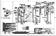
The following is typical example of how to determine the relay settings for a specific motor<br />
that has been applied conservatively. This is only an example and may not address all<br />
issues relating to your specific application. It is recommended that your local protection<br />
engineer determine the settings for your motor protective relaying application. Refer to<br />
following figures for schematic diagrams related to this example.<br />
Important points to keep in mind before developing settings for any multifunction<br />
numerical device like the 469 Motor Management Relay:<br />
• Gather system data, including, but not limited to:<br />
– CT primary and secondary ratings for all the CTs used to feed the relay<br />
– motor name plate data<br />
– motor operating curves (typical set shown below)<br />
Time (sec.)<br />
1000.000<br />
100.000<br />
10.000<br />
1.000<br />
0 500 1,000 1,500 2,000 2,500<br />
Current (Amps)<br />
FIGURE 1–1: Typical Motor Curves<br />
806553A1.CDR<br />
469 MOTOR MANA<strong>GE</strong>MENT RELAY – INSTRUCTION MANUAL 1–17
– VT primary and secondary ratings<br />
– System frequency<br />
– System phase sequence<br />
CHAPTER 1: <strong>GE</strong>TTING STARTED<br />
• Define the protection elements that will be enabled. Prepare a list of protection<br />
functions including the following information. By default, all the protection functions<br />
must be assumed “Disabled”:<br />
– Pickup parameter<br />
– Operating curve, if applicable<br />
– Time dial or multiplier<br />
– Any additional intentional time delay<br />
– Directionality, if applicable<br />
• Define how many output contacts will be energized in response to a given protection<br />
function. Note that the 469 relay can be programmed to Trip or Alarm and, at the<br />
same time, to energize one, a combination, or all the 2 auxiliary relays during the<br />
process.<br />
• Define if the output relays will be set as failsafe type.<br />
• Define if the 469 relay will be used to start the motor. If so, gather information on the<br />
required conditions to execute the command.<br />
• Define if the 469 will be involved in the motor starting process, particularly on reduced<br />
voltage start applications.<br />
• Define if the 469 will be applied a multi speed applications.<br />
• Define if the relay will be used to monitor the status of the starter or breaker. It is<br />
strongly recommended that the 469 be always programmed to monitor the status of<br />
the disconnecting device, by means of a dry contact connected to one of the digital<br />
inputs of the relay. Use an auxiliary contact from the breaker or starter either a<br />
normally open contact, 52a, which is normally in open position when the<br />
disconnecting device is open, or a normally closed contact, 52b, which is in close<br />
position when the breaker or starter is open.<br />
• If the 469 will be used to respond to digital inputs, record the following information:<br />
– <strong>Digital</strong> Input name<br />
– Condition by which the digital input would be considered asserted<br />
– Function that the digital input will initiate within the 469<br />
• If the 469 will be used to perform monitoring functions and act upon certain<br />
conditions, record information such as:<br />
– minimum and maximum values<br />
– alarm and trip values<br />
– time delays<br />
• It is important to familiarize yourself with the relay protection and control functions<br />
before setting up the relay.<br />
1–18 469 MOTOR MANA<strong>GE</strong>MENT RELAY – INSTRUCTION MANUAL
CHAPTER 1: <strong>GE</strong>TTING STARTED<br />
To begin, simply power on the unit and follow the instructions in this tutorial. Assume the<br />
following system characteristics and that the 469 settings are unaltered from their factory<br />
default values.<br />
Refer to the following figures for schematics related to this application example.<br />
469 MOTOR MANA<strong>GE</strong>MENT RELAY – INSTRUCTION MANUAL 1–19
+<br />
Comp<br />
-<br />
Shld<br />
+<br />
Comp<br />
-<br />
Shld<br />
+<br />
Comp<br />
-<br />
Shld<br />
+<br />
Comp<br />
-<br />
Shld<br />
+<br />
Comp<br />
-<br />
Shld<br />
+<br />
Comp<br />
-<br />
Shld<br />
+<br />
Comp<br />
-<br />
Shld<br />
+<br />
Comp<br />
-<br />
Shld<br />
+<br />
Comp<br />
1<br />
2<br />
3<br />
4<br />
5<br />
6<br />
7<br />
8<br />
9<br />
10<br />
11<br />
12<br />
13<br />
14<br />
15<br />
16<br />
17<br />
18<br />
19<br />
20<br />
21<br />
22<br />
23<br />
24<br />
25<br />
26<br />
27<br />
28<br />
29<br />
30<br />
31<br />
32<br />
33<br />
34<br />
35<br />
36<br />
STATOR<br />
PHASE A - 1<br />
STATOR<br />
PHASE A - 2<br />
STATOR<br />
PHASE B - 1<br />
STATOR<br />
PHASE B - 2<br />
FIGURE 1–2: Typical Relay Connection Diagram<br />
CHAPTER 1: <strong>GE</strong>TTING STARTED<br />
1–20 469 MOTOR MANA<strong>GE</strong>MENT RELAY – INSTRUCTION MANUAL<br />
STATOR<br />
PHASE C - 1<br />
STATOR<br />
PHASE C - 2<br />
MOTOR<br />
BEARING 1<br />
MOTOR<br />
BEARING 2<br />
MOTOR<br />
AMBIENT<br />
-<br />
Shld<br />
806554A2.CDR
CHAPTER 1: <strong>GE</strong>TTING STARTED<br />
FIGURE 1–3: Typical Control Diagram<br />
806552A2.CDR<br />
469 MOTOR MANA<strong>GE</strong>MENT RELAY – INSTRUCTION MANUAL 1–21<br />
COMMON
806551A1.CDR<br />
FIGURE 1–4: Typical Breaker Control Diagram<br />
CHAPTER 1: <strong>GE</strong>TTING STARTED<br />
1–22 469 MOTOR MANA<strong>GE</strong>MENT RELAY – INSTRUCTION MANUAL
CHAPTER 1: <strong>GE</strong>TTING STARTED<br />
• Power System Data<br />
a) System: 3Φ, 4 wire<br />
b) Frequency: 60 Hz<br />
c) Line voltage: 600 V<br />
• Motor Data<br />
FIGURE 1–5: Typical Relay Control Diagram<br />
As per the following motor data sheet information:<br />
FIGURE 1–6: Motor Data Sheet Information<br />
806555A2.CDR<br />
469 MOTOR MANA<strong>GE</strong>MENT RELAY – INSTRUCTION MANUAL 1–23<br />
COMMON
• Motor Operating Curves<br />
Motor operating curves as shown below:<br />
CHAPTER 1: <strong>GE</strong>TTING STARTED<br />
FIGURE 1–7: Motor Operating Curves for Application Example<br />
• Control System Requirements<br />
– All protection elements trip the breaker<br />
– Breaker position monitoring via 52b contact only<br />
– Only current metering is required<br />
– Serial communication remote start from RTU<br />
– Alarm after 100 s delay from station monitor. This is normally used to signal the<br />
remote center when someone has gained access to the substation.<br />
• Contact Outputs<br />
– Trip and close to breaker control circuit (Trip and Auxiliary2 relays)<br />
– Relay failure alarm to RTU (self-test warning relay, no programming required)<br />
– Alarm contact (setup in General Sw. A for “Station Monitor”)<br />
– No data communications to other equipment.<br />
1–24 469 MOTOR MANA<strong>GE</strong>MENT RELAY – INSTRUCTION MANUAL
CHAPTER 1: <strong>GE</strong>TTING STARTED<br />
• RTDs<br />
The motor is fitted with the following RTDs:<br />
– RTD type: 100 Ω Platinum<br />
– 6 Stator RTDs, 2 per phase<br />
– 2 Bearing RTDs<br />
– 1 Ambient RTD<br />
Use the above data to set the output relays to achieve breaker control; to set digital inputs<br />
for breaker status, remote operations, remote status, and alarm indication. Assume that<br />
the communications between the station and the master control center will be done by the<br />
RTU. Alarms, status indication, and breaker commands will be hard-wired from the relay to<br />
the RTU. Similar information could be exchanged between the RTU and the relay via an<br />
RS485 or RS422 Serial Link using the Modbus RTU protocol. Refer to <strong>GE</strong> Publication <strong><strong>GE</strong>K</strong>-<br />
106491C: 469 Communications Guide for additional information.<br />
1.4.2 Instrument Transformer Data<br />
1.4.3 Motor Protection<br />
• Voltage Transformers<br />
– 2 × Open Delta connected, ratio = 600:120 V<br />
– Motor System Voltage = 575 V<br />
• Phase CTs<br />
The phase CTs should be chosen such that the FLC is 50% to 100% of CT primary.<br />
Since the FLC is 347.5A a 350:5, or 400:5 CT may be chosen; 400:5 is a standard<br />
available size and so would probably be selected.<br />
• Ground CT<br />
For high resistive grounded systems, sensitive ground detection is possible with the<br />
50:0.025 CT. Use a 1 A or 5 A secondary CT on solidly grounded or low resistive<br />
grounded systems where the fault current is much higher. If a residual connection is<br />
chosen, pickup levels and timers must be set with respect to the acceleration time.<br />
The chosen zero-sequence CT must be able to handle all potential fault levels without<br />
saturating. In this example, 50:5A CT is selected.<br />
• Motor FLC<br />
Set the motor full load current to 348 A, as specified by the data sheets.<br />
Use the above data to set the relay system parameters, such as CT and VT<br />
connections, VT secondary voltage, and CT and VT primary to secondary ratios.<br />
• Overload Pickup<br />
The overload pickup is set to the maximum allowed by the service factor of the motor.<br />
Since this motor has RTDs and the relay will be using the RTD bias feature for<br />
enhanced protection, set the overload pickup to the highest setting of 1.25 x FLC for<br />
the motor service factor of 1.15. If service factor is unknown, assume 1.0.<br />
• Overload Curve<br />
469 MOTOR MANA<strong>GE</strong>MENT RELAY – INSTRUCTION MANUAL 1–25
CHAPTER 1: <strong>GE</strong>TTING STARTED<br />
Select the standard overload curve to be just below the cold thermal limit to give<br />
maximum process uptime, without compromising protection.<br />
The best fitting curve is curve 7 (see figure below)<br />
1–26 469 MOTOR MANA<strong>GE</strong>MENT RELAY – INSTRUCTION MANUAL
CHAPTER 1: <strong>GE</strong>TTING STARTED<br />
469 Motor Management Relay<br />
STANDARD OVERLOAD CURVES<br />
100000<br />
10000<br />
FIGURE 1–8: Overload Curve Matching (Example)<br />
469 MOTOR MANA<strong>GE</strong>MENT RELAY – INSTRUCTION MANUAL 1–27<br />
1000<br />
100<br />
TIME IN SECONDS<br />
x15<br />
10<br />
x1<br />
1.00<br />
0.10 1.00<br />
10 100 1000<br />
806804A5.CDR<br />
MULTIPLE OF FULL LOAD AMPS<br />
BA JN <strong>GE</strong> ORDER NUMBER ADDED<br />
Deleted “Multilin” from logo<br />
A5 12/99 469-202 WL CD<br />
Deleted “SR” from Heading<br />
A4 06/98 469-096<br />
REV DATE ECO# DWN APP DESCRIPTION<br />
THIS DRAWING IS PROPRIETARY INFORMATION<br />
NOTE:<br />
LOG CHART SCALED AS PER:<br />
KEUFFEL & ESSER TIME-CURRENT CHARACTERISTIC PAPER<br />
TEL: (905)294-6222 FAX: (905)201-2098<br />
INT: http://www.ge.com/edc/pm<br />
215 ANDERSON AVENUE,<br />
MARKHAM, ONT., CANADA, L6E 1B3<br />
469 Motor Management Relay<br />
STANDARD OVERLOAD CURVES<br />
REV.<br />
806804A5.CDR<br />
N/A<br />
DWG. No.:<br />
A5<br />
DRAWN BY/DATE:<br />
ENG. APP./DATE:<br />
MFG. APP./DATE:<br />
SCALE: DWG. SIZE: B<br />
JA/09/20/96<br />
X<br />
X<br />
<strong>GE</strong> ORDER #: <strong>GE</strong>S10083<br />
PART No.:<br />
1:1
• Short Circuit Trip<br />
CHAPTER 1: <strong>GE</strong>TTING STARTED<br />
The short circuit trip should be set above the maximum locked rotor current but below<br />
the short circuit current of the fuses. The data sheets indicate a maximum locked rotor<br />
current of 630% FLC or 6.3 × FLC. A setting of 7 × FLC with a instantaneous time delay<br />
will be ideal but nuisance tripping may result due to the asymmetrical starting<br />
currents and DC offset. If asymmetrical starting currents limits the starting capability,<br />
set the S/C level higher to a maximum of 11 × FLC to override this condition<br />
(1.7 × 6.3 = 11.7 where 1.7 is the maximum DC offset for an asymmetrical current).<br />
• Ground Fault<br />
Unfortunately, there is not enough information to determine a ground fault setting.<br />
These settings depend on the following information:<br />
1. The ground fault current available.<br />
2. System grounding; for example, high resistive grounding or solidly grounded<br />
3. Ground fault CT used.<br />
4. Ground fault connection; for example, zero-sequence or residual connection<br />
For the purpose of this example, assume a fault current of 10 Amps or 10/50 = 0.2 x<br />
CT, no intentional time delay.<br />
• Unbalance Alarm and Trip<br />
The unbalance settings are determined by examining the motor application and<br />
motor design. The heating effect of unbalance will be protected by enabling<br />
unbalance input to thermal memory; described in details in Chapter 5, Thermal Model.<br />
A setting of 10% for the unbalance alarm with a delay of 10 seconds would be<br />
appropriate and the trip can be set to 25% with a delay of 5 seconds.<br />
• Stopped and Running Cool Times<br />
The motor manufacturer usually supplies this information as either cooling times, or<br />
cooling time constants not provided in the data sheet issued with this motor. Since<br />
RTDs are present and wired to the relay, biasing of the thermal model will be used so it<br />
is not critical to have these cooling times from the manufacturer. The default values of<br />
motor cooling time constants are 15 and 30 minutes, and can be used for the running<br />
and stopped cool times respectively. If the manufacturer provides cooling times<br />
instead, the approximate values of the cooling time constants is 1/5th the cooling<br />
times provided by the manufacturer.<br />
• Acceleration Trip<br />
This settings should be set higher than the maximum starting time to avoid nuisance<br />
tripping when the voltage is lower or for varying loads during acceleration. If reduced<br />
voltage starting is used, according to the acceleration curves, a setting of 18 seconds<br />
would be appropriate, or if across the line starting is used, a setting of 13 seconds<br />
would be appropriate.<br />
• Enable Start Inhibit<br />
This function will limit starts when the motor is already hot. The relay learns the<br />
amount of thermal capacity used at start. If the motor is hot, thus having some<br />
thermal capacity used, the relay will not allow a start if the available thermal capacity<br />
is less than the required thermal capacity for a start.<br />
1–28 469 MOTOR MANA<strong>GE</strong>MENT RELAY – INSTRUCTION MANUAL
CHAPTER 1: <strong>GE</strong>TTING STARTED<br />
• Starts/Hour<br />
When available, set starts/Hour to the number of cold starts as per the data sheet.<br />
• Time Between Starts<br />
In some cases, the motor manufacturer will specify the time between motor starts.<br />
This information is not given so this feature can be left disabled. If the information is<br />
available, the time provided on the motor data sheets should be programmed.<br />
• Stator RTDs<br />
Set the RTD trip level at or below the maximum temperature rating of the insulation.<br />
The data available shows class F insulation (temperature rating of 155°C), therefore<br />
the Stator RTD Trip level should be set to between 140°C to 155°C, with 155°C being<br />
maximum. The RTD alarm level should be set to provide a warning that the motor<br />
temperature is rising. For this example, 135°C would be appropriate since this motor is<br />
designed for class B rise, 130°C is it's normal hot operating temperature.<br />
• Bearing RTDs<br />
The Bearing RTD alarm and trip settings will be determined by evaluating the<br />
temperature specification from the bearing manufacturer.<br />
• Unbalance bias of thermal capacity<br />
Enable the Unbalance Bias of Thermal Capacity so that the heating effect of<br />
unbalance currents is added to the Thermal Capacity Used.<br />
• Unbalance bias K factor<br />
The K value is used to calculate the contribution of the negative-sequence current<br />
flowing in the rotor due to unbalance. It is defined as:<br />
where: R r2 = rotor negative-sequence resistance<br />
R r1 = rotor positive-sequence resistance.<br />
(EQ 1.1)<br />
A formula based on empirical data states that K is equal to 230 divided by the per-unit<br />
locked rotor current squared.<br />
From the data sheet, the locked rotor amps = 631% FLA or 6.31 × FLA. Therefore,<br />
• Hot/cold curve ratio<br />
(EQ 1.2)<br />
The hot/cold curve ratio is calculated by simply dividing the hot safe stall time by the<br />
cold safe stall time or use the motor thermal limits curve. For this example, both are<br />
available. Using the data sheets the, safe stall time H/C or hot/cold curve ratio is given<br />
as 16/18 = 0.89<br />
• Enable RTD Biasing<br />
This will enable the temperature from the Stator RTD sensors, to be included in the<br />
calculations of thermal capacity. This model determines the thermal capacity used<br />
based on the temperature of the Stator and is separate from the overload model for<br />
calculating thermal capacity used.<br />
469 MOTOR MANA<strong>GE</strong>MENT RELAY – INSTRUCTION MANUAL 1–29<br />
K<br />
Rr2 = -------<br />
Rr1 K<br />
230<br />
(per-unit locked rotor amps) 2<br />
230<br />
------------------------------------------------------------------------<br />
6.312 = =<br />
------------ ≈ 6
1.4.4 S2 System Settings<br />
CHAPTER 1: <strong>GE</strong>TTING STARTED<br />
RTD biasing is a back up protection element, which accounts for such things as loss of<br />
cooling or unusually high ambient temperature. This measured temperature is used to<br />
bias or modify the thermal capacity value stored in the relay.<br />
RTD BIAS MINIMUM: Set to 40°C, which is the ambient temperature, obtained from the<br />
data sheets.<br />
RTD BIAS MID POINT: The center point temperature is set to the motor's hot running<br />
temperature and is calculated as follows:<br />
Temperature Rise of Stator + Ambient Temperature<br />
The temperature rise of the stator is 80°C (class F rise by resistance) + 10% hot spot<br />
allowance, obtained from the data sheets. Therefore, the RTD Center point<br />
temperature is set to 90°C + 40°C or 130°C.<br />
RTD BIAS MAXIMUM: This settings is set to the rating of the insulation or slightly less. A<br />
class F insulation is used in this motor which is rated at 155°C, so the setting should be<br />
“155”.<br />
FIGURE 1–9: RTD Bias Example 1<br />
806550A1.CDR<br />
You should now be familiar with maneuvering through and editing settings messages. As<br />
such, we will now limit our discussion to just the values that must be programmed to meet<br />
the requirements of the example application. Any settings not explicitly mentioned should<br />
be left at the factory default value.<br />
The S2 settings page contains settings for entering the characteristics of the equipment on<br />
the motor electrical system. In our example, these characteristics are specified under the<br />
Power System Data and Instrument Transformer Data headings in the previous subsection.<br />
From this information and the resulting calculations, program the page S2 settings<br />
as indicated.<br />
1–30 469 MOTOR MANA<strong>GE</strong>MENT RELAY – INSTRUCTION MANUAL
CHAPTER 1: <strong>GE</strong>TTING STARTED<br />
For current transformers, make the following change in the S2 SYSTEM SETUP CURRENT<br />
SENSING settings page:<br />
PHASE CT PRIMARY: “400 A”<br />
MOTOR FULL LOAD AMPS FLA: “348 A”<br />
GROUND CT: “5 A Secondary”<br />
GROUND CT PRIMARY: “50 A”<br />
PHASE DIFFERENTIAL CT: “None”<br />
ENABLE 2-SPEED MOTOR PROTECTION: “No”<br />
For current transformers, make the following change in the S2 SYSTEM SETUP VOLTA<strong>GE</strong><br />
SENSING settings page:<br />
VT CONNECTION TYPE: “Open Delta”<br />
ENABLE SINGLE VT OPERATION: “Off”<br />
VOLTA<strong>GE</strong> TRANSFORMER RATIO: “5 : 1”<br />
(for a 600 V system, 600/120 V = 5, where 5 is the VT ratio)<br />
MOTOR NAMEPLATE VOLTA<strong>GE</strong>: “575 V”<br />
The 469 Motor Management Relay was designed with the ability to display primary system<br />
values. Current and voltage measurements are performed at secondary levels, which the<br />
relay transforms to primary values using CT and VT ratios, system voltage, as well as the<br />
nominal secondary values.<br />
In the case of the phase CTs, configuring the relay for current measurements is simple and<br />
it only requires inputting the CT primary current. Phase CT inputs can be 1 A or 5 A, and<br />
they must be specified when the relay is purchased.<br />
There is more flexibility with regards to Ground CT inputs, as well as VT inputs, where<br />
nominal values are not required ahead of time, before the relay is ordered; therefore more<br />
settings are needed to set the relay for measurements.<br />
Make the following change in the S2 SYSTEM SETUP POWER SYSTEM settings page to<br />
reflect the power system:<br />
NOMINAL SYSTEM FREQUENCY: “60 Hz”<br />
SYSTEM PHASE SEQUENCE: “ABC”<br />
The example calls for remote control via serial communications, received from the master<br />
station, through the RTU. Motor starting and stopping is possible via any of the three 469<br />
communication ports.<br />
When a start command is issued, the auxiliary relay assigned for starting control is<br />
activated for 1 second to complete the close coil circuit for a breaker application, or<br />
complete the start control circuit for a contactor application. A contactor sealing contact<br />
would be used to maintain the circuit. For details on issuing a start or stop command via<br />
communications, refer to the <strong>GE</strong> Publication <strong><strong>GE</strong>K</strong>-106491: 469 Communications Guide.<br />
Make the following changes to the communications settings in the S2 SYSTEM SETUP <br />
SERIAL COMM. CONTROL page.<br />
SERIAL COMMUNICATION CONTROL: “On”<br />
ASSIGN START CONTROL RELAYS: “Auxiliary2”<br />
The Auxiliary 2 relay will be used to start the motor. Note that this auxiliary relay can not be<br />
used for any other application.<br />
469 MOTOR MANA<strong>GE</strong>MENT RELAY – INSTRUCTION MANUAL 1–31
CHAPTER 1: <strong>GE</strong>TTING STARTED<br />
Once the signal is received the motor will be started across the line. Therefore, the<br />
following settings are left with their default values. In the S2 SYSTEM SETUP REDUCE<br />
VOLTA<strong>GE</strong> STARTING settings page:<br />
REDUCE VOLTA<strong>GE</strong> STARTING: “Off”<br />
ASSIGN CONTROL RELAYS: “Auxiliary3” (available for other use)<br />
TRANSITION ON: “Current Only”<br />
ASSIGN TRIP RELAYS: “Trip”<br />
REDUCE VOLTA<strong>GE</strong> START LEVEL: “100% FLA”<br />
REDUCE VOLTA<strong>GE</strong> START TIMER: “200 s”<br />
1.4.5 S3 <strong>Digital</strong> Inputs Settings<br />
The S3 settings page is for entering the characteristics of the digital inputs. In our example,<br />
these characteristics are specified under the Control System Requirements heading.<br />
Program the S3 settings as indicated.<br />
Some of the functions assigned to the digital inputs of the 469 Motor Management Relay<br />
are pre-defined functions, which can be selected from a list. There are four user-defined<br />
functions, called General Switch A to D, associated to the assignable inputs. Set these<br />
inputs to operate output relays, with or without delay, responding to the status change of<br />
dry contacts connected to the digital input terminals. Use the following procedure to set<br />
these functions:<br />
Change the default names to meaningful values so they can be<br />
easily identified, either via the LCD or when reviewing event reports.<br />
Identify their asserted logic.<br />
Define the functionality of the digital inputs.<br />
All the other assignable input functions are pre-defined, and when selected, they can be<br />
set to generate Trip or Alarms, as well as energize auxiliary outputs as needed.<br />
For breaker position monitoring, set the following pre-defined <strong>Digital</strong> Input called “Starter<br />
Status”. As per the information provided above, a 52b contact will be used, and must be<br />
connected between terminals D16 to D23:<br />
S3 DIGITAL INPUTS STARTER STATUS STARTER STATUS SW: “Starter Auxiliary b”<br />
To set the relay to monitor access to the station, use Assignable Input 1 as “General Switch<br />
A”, as follows. To define the digital input, enter the following data in the S3 DIGITAL INPUTS<br />
ASSIGNABLE INPUT 1 settings page.<br />
To identify the digital input:<br />
INPUT 1 FUNCTION: “General Sw. A”<br />
SWITCH NAME: “Stn. Monitor”<br />
To define the asserted logic:<br />
<strong>GE</strong>NERAL SWITCH A: “Normally Open”<br />
To define the functionality:<br />
BLOCK INPUT FROM START: “0 s”<br />
<strong>GE</strong>NERAL SWITCH A ALARM: “Latched”<br />
ASSIGN ALARM RELAYS: “Alarm”<br />
1–32 469 MOTOR MANA<strong>GE</strong>MENT RELAY – INSTRUCTION MANUAL
CHAPTER 1: <strong>GE</strong>TTING STARTED<br />
1.4.6 S5 Thermal Model<br />
<strong>GE</strong>NERAL SWITCH A ALARM DELAY: “5.0 s”<br />
<strong>GE</strong>NERAL SWITCH A EVENTS: “On” so this event is registered.<br />
<strong>GE</strong>NERAL SWITCH A TRIP: “Off”<br />
If the relay will not be used to trip the motor when someone gains unauthorized access to<br />
the station, the next settings should be left at their default values:<br />
<strong>GE</strong>NERAL SWITCH A TRIP: “Off”<br />
ASSIGN TRIP RELAYS: “Trip”<br />
<strong>GE</strong>NERAL SWITCH A TRIM DELAY: “5.0 s”<br />
The S5 Thermal Model settings page contains settings for entering settings related to<br />
protection of the motor during the starting process as well as during normal operation.<br />
As per the information provided above, the settings for the Thermal Model are entered as<br />
follows in the<br />
SELECT CURVE STYLE: “Standard”<br />
OVERLOAD PICKUP: “1.25 x FLA”<br />
ASSIGN TRIP RELAYS: “Trip”<br />
UNBALANCE BIAS K FACTOR: “6”<br />
COOL TIME CONSTANT RUNNING: “15 min.”<br />
COOL TIME CONSTANT STOPPED: “30 min.”<br />
HOT/COLD SAFE STALL RATIO: “0.89”<br />
ENABLE RTD BIASING: “Yes”<br />
RTD BIAS MINIMUM: “40°C” – ambient temperature<br />
RTD BIAS CENTER POINT: “130°C” – center value<br />
RTD BIAS MAXIMUM: “155°C” – maximum value<br />
THERMAL CAPACITY ALARM: “Unlatched” – recommended for early warning to take<br />
corrective actions and prevent the interruption of the process.<br />
ASSIGN ALARM RELAYS: “Alarm” – the Alarm contact could be use for local indication,<br />
or to send a local signal to reduce load, before a trip is issued.<br />
THERMAL CAP. ALARM LEVEL: “80%”<br />
THERMAL CAPACITY ALARM EVENT: “Yes” – captures event in the event report.<br />
As well, select the overload curve for the Thermal model with the following settings in the<br />
S5 THERMAL MODEL OVERLOAD CURVE SETUP menu:<br />
STANDARD OVERLOAD CURVE NUMBER: “7”<br />
1.4.7 S6 Current Elements<br />
The S6 Current Elements settings page contains settings for entering protection element<br />
characteristics. In our example, these characteristics are specified under Motor Protection<br />
heading.<br />
From this data and the resulting calculations, program the S6 settings page as indicated.<br />
When setting the relay for the first time, other settings not listed in this example should be<br />
left disabled.<br />
469 MOTOR MANA<strong>GE</strong>MENT RELAY – INSTRUCTION MANUAL 1–33
CHAPTER 1: <strong>GE</strong>TTING STARTED<br />
For the Short Circuit element, enter the following values in the S6 CURRENT ELEMENTS <br />
SHORT CIRCUIT TRIP page. Press the MESSA<strong>GE</strong> key after each settings is entered to<br />
move to the next message.<br />
SHORT CIRCUIT TRIP: “Latched”<br />
SHORT CIRCUIT TRIP OVEREACH FILETER: “Off” - no filtering of DC component is<br />
required (refer to Short Circuit Trip on page 5–59 for additional information)<br />
ASSIGN TRIP RELAYS: “Trip”<br />
SHORT CIRCUIT TRIP PICKUP: “11.7”<br />
INTENTIONAL S/C TRIP DELAY: “0 ms” - Instantaneous trip is required.<br />
SHORT CIRCUIT TRIP BACKUP: “On” - if the main disconnect device does not respond to<br />
the trip command, a second signal will be initiated via an auxiliary relay to generate a<br />
bus shot down; in most cases, the second trip command energizes a lock out relay (86)<br />
which is used to trip the upstream breakers<br />
ASSIGN BACKUP RELAYS: “Auxiliary3”<br />
SHORT CIRCUIT TRIP BACKUP DELAY: “200 ms” - this time must be greater than the<br />
total time required to trip the main breaker plus a margin<br />
Since the specifications do not indicate values for the following features, they must be left<br />
“Off”:<br />
OVERLOAD ALARM: “Off”<br />
MECHANICAL JAM: “Off”<br />
UNDERCURRENT: “Off”<br />
PHASE DIFFERENTIAL: “Off”<br />
For the Ground Fault element, enter the following values in the S6 CURRENT ELEMENTS <br />
GROUND FAULT page. Press the MESSA<strong>GE</strong> key after each settings is entered to move to<br />
the next message.<br />
GROUND FAULT OVERREACH FILETER: “Off” – no filtering of DC component is required<br />
(refer to Ground Fault on page 5–63 for additional information)<br />
GROUND FAULT ALARM: “Off” – default setting, no Alarm is required<br />
ASSIGN ALARM RELAYS: “Alarm” – default setting<br />
GROUND FAULT ALARM PICKUP: “0.10 x CT” – default setting<br />
INTENTIONAL GF ALARM DELAY: “0 ms” – default setting<br />
GROUND FAULT ALARM EVENTS: “Off” – default setting<br />
GROUND FAULT TRIP: “Latched” – the output relay will remind energized until the Reset<br />
command executed<br />
ASSIGN TRIP RELAYS: “Trip”<br />
GROUND FAULT TRIP PICKUP: “0.20 x CT”<br />
INTENTIONAL GF TRIP DELAY: “0 ms”<br />
GROUND FAULT TRIP BACKUP: “On”<br />
ASSIGN BACKUP RELAYS: “Auxiliary3” - same relay assigned for the Short Circuit Trip<br />
Backup<br />
GROUND FAULT TRIP BACKUP DELAY: “200 ms” - same time delay assigned to the Short<br />
Circuit Trip Backup<br />
For the Current Unbalance element, enter the following values in the S6 CURRENT<br />
ELEMENTS CURRENT UNBALANCE page. Press the MESSA<strong>GE</strong> key after each settings<br />
is entered to move to the next message.<br />
1–34 469 MOTOR MANA<strong>GE</strong>MENT RELAY – INSTRUCTION MANUAL
CHAPTER 1: <strong>GE</strong>TTING STARTED<br />
1.4.8 S7 Motor Starting<br />
1.4.9 S8 RTD Temperature<br />
CURRENT UNBALANCE ALARM: “Unlatched”<br />
ASSIGN ALARM RELAYS: “Alarm”<br />
CURRENT UNBALANCE ALARM PICKUP: “10%”<br />
CURRENT UNBALANCE ALARM DELAY: “10 s”<br />
CURRENT UNBALANCE ALARM EVENTS: “On”<br />
CURRENT UNBALANCE TRIP: “Latched” – the output relay will remind energized until the<br />
Reset command executed<br />
ASSIGN TRIP RELAYS: “Trip”<br />
CURRENT UNBALANCE TRIP PICKUP: “20%”<br />
CURRENT UNBALANCE TRIP DELAY: “5 s”<br />
The S7 Motor Starting settings page contains additional settings used to complement the<br />
Thermal Model. In our example, these characteristics are specified under Motor Protection<br />
heading.<br />
For the Acceleration Timer element, enter the following values in the S7 MOTOR STARTING <br />
ACCELERATION TIMER page. Press the MESSA<strong>GE</strong> key after each settings is completed to<br />
move to the next message.<br />
ACCELERATION TIMER TRIP: “Latched”<br />
ASSIGN TRIP RELAYS: “Trip”<br />
ACCELERATION TIMER FROM START: “13 s” – as shown in the acceleration curves at<br />
100% voltage<br />
For the Start Inhibit element, enter the following values in the S7 MOTOR STARTING <br />
START INHIBIT page. Press the MESSA<strong>GE</strong> key after each settings is completed to move<br />
to the next message.<br />
START INHIBIT BLOCK: “On”<br />
TC USED MARGIN: “25%”<br />
With these settings, the 469 relay prevents motor starting if there is insufficient thermal<br />
capacity for a successful motor start. Refer to Start Inhibit on page 5–66 for additional<br />
information.<br />
There is not information available to set Starts/Hour, Time Between Starts, or the Restart<br />
Block features. Therefore, the following settings must be disabled:<br />
JOGGING BLOCK: “Off”<br />
RESTART BLOCK: “Off”<br />
The S8 RTD Temperature page contains the settings for the twelve (12) field programmable<br />
RTDs that are normally used for temperature monitoring. The temperature measured by<br />
each RTD can be compared to pickup values, and set to energize Trip or Alarm outputs.<br />
For proper temperature monitoring, enter the RTD types in the S8 RTD TEMPERTURE RTD<br />
TYPES page. Press the MESSA<strong>GE</strong> key after each settings is completed to move to the<br />
next message.<br />
469 MOTOR MANA<strong>GE</strong>MENT RELAY – INSTRUCTION MANUAL 1–35
1.4.10 Other Settings<br />
STATOR RTD TYPE: “100 Ohm Platinum”<br />
BEARING RTD TYPE: “100 Ohm Platinum”<br />
AMBIENT RTD TYPE: “100 Ohm Platinum”<br />
OTHER RTD TYPE: “100 Ohm Platinum” – default value<br />
CHAPTER 1: <strong>GE</strong>TTING STARTED<br />
As per the information provided above, there will be six RTDs, two per phase located in the<br />
Stator, and two Bearing RTDs, one to monitor the ambient temperature.<br />
For Stator Overtemperature protection, enter the following settings in the S8 RTD<br />
TEMPERTURE RTD 1 to RTD6 menus:<br />
RTD #1 APPLICATION: “Stator”<br />
RTD #1 NAME: “ST Ph A1”<br />
RTD #1 ALARM: “Unlatched”<br />
ASSIGN ALARM RELAYS: “Alarm”<br />
RTD #1 ALARM TEMPERATURE: “135°C”<br />
RTD #1 HIGH ALARM: “Off”<br />
HIGH ALARM RELAYS: “Alarm” - default value<br />
RTD #1 HIGH ALARM TEMPERATURE: “135°C” - default value<br />
RTD #1 ALARM EVENTS: “On”<br />
RTD #1 TRIP: “Latched”<br />
RTD #1 TRIP VOTING: “RTD #5”<br />
ASSIGN TRIP RELAYS: “Trip”<br />
RTD #1 TRIP TEMPERATURE: “155°C”<br />
The settings for the other RTDs are entered in similar fashion. Refer to S8 RTD Temperature<br />
on page 5–70 for additional settings and additional information on RTD monitoring.<br />
Undervoltage Protection<br />
In addition to the settings illustrated above, there will be cases in motor applications where<br />
additional settings will be required, to monitor other system parameters such as voltage<br />
levels.<br />
The following sub-section will illustrate the procedures to set the 469 Motor Management<br />
Relay to meet those requirements.<br />
Description<br />
Using the same system information, the following example illustrates the steps to set the<br />
469 for Undervoltage protection.<br />
The following settings are provided:<br />
Pickup: 70% of nominal voltage – starting<br />
80% of nominal voltage – running<br />
Time Delay: 13.0 s<br />
Other Considerations<br />
• The function will be active only if there is voltage in the line feeding the motor, to avoid<br />
nuisance trips due to the lack of voltage. The 469 will consider the bus energized only<br />
1–36 469 MOTOR MANA<strong>GE</strong>MENT RELAY – INSTRUCTION MANUAL
CHAPTER 1: <strong>GE</strong>TTING STARTED<br />
if the measured voltage is greater than 20% of nominal voltage. A trip condition will be<br />
initiated only if undervoltage is detected in all the phases.<br />
• In order to monitor for VT Fuse Failure or to monitor for undervoltage in one phase<br />
only, set an Alarm when the voltage is 90% of nominal voltage both during start and<br />
running.<br />
For the Undervoltage element, enter the following values in the S9 VOLTA<strong>GE</strong> ELEMENTS <br />
UNDERVOLTA<strong>GE</strong> settings page. Press the ENTER key to save, and then the MESSA<strong>GE</strong> key,<br />
after each settings is completed, to move to the next message:<br />
U/V ACTIVE ONLY IF BUS ENERGIZED: “Yes”<br />
UNDERVOLTA<strong>GE</strong> ALARM: “Unlatched”<br />
ASSIGN ALARM RELAYS: “Alarm”<br />
UNDERVOLTA<strong>GE</strong> ALARM PICKUP: “0.9 x RATED”<br />
STARTING U/V ALARM PICKUP: “0.9 x RATED”<br />
UNDERVOLTA<strong>GE</strong> ALARM DELAY: “0.0 s”<br />
UNDERVOLTA<strong>GE</strong> ALARM EVENTS: “Yes”<br />
UNDERVOLTA<strong>GE</strong> TRIP: “Latched”<br />
UNDRVOLTA<strong>GE</strong> TRIP MODE: “3-Phase”<br />
ASSIGN TRIP RELAYS: “Trip”<br />
UNDERVOLTA<strong>GE</strong> TRIP PICKUP: “0.8 x RATED”<br />
STARTING U/V TRIP PICKUP: “0.7 x RATED”<br />
UNDERVOLTA<strong>GE</strong> TRIP DELAY: “13.0 s”<br />
469 MOTOR MANA<strong>GE</strong>MENT RELAY – INSTRUCTION MANUAL 1–37
1.5 Installation<br />
1.5.1 Testing<br />
CHAPTER 1: <strong>GE</strong>TTING STARTED<br />
Extensive commissioning tests are available in Chapter 7. Tables for recording required<br />
settings are available in Microsoft Excel format from the <strong>GE</strong> <strong>Digital</strong> <strong>Energy</strong> website at http:/<br />
/www.gedigitalenergy.com/. The website also contains additional technical papers and<br />
FAQs relevant to the 469 Motor Management Relay.<br />
1–38 469 MOTOR MANA<strong>GE</strong>MENT RELAY – INSTRUCTION MANUAL
<strong>GE</strong><br />
<strong>Digital</strong> <strong>Energy</strong><br />
2.1 Overview<br />
2.1.1 Description<br />
469 Motor Management Relay<br />
Chapter 2: Introduction<br />
Introduction<br />
The 469 Motor Management Relay is a microprocessor based relay designed for the<br />
protection and management of medium and large horsepower motors and driven<br />
equipment. The 469 is equipped with six (6) output relays for trips, alarms, and start blocks.<br />
Motor protection, fault diagnostics, power metering, and RTU functions are integrated into<br />
one economical drawout package. The single-line diagram below illustrates the 469<br />
functionality using ANSI (American National Standards Institute) device numbers<br />
469 MOTOR MANA<strong>GE</strong>MENT RELAY – INSTRUCTION MANUAL 2–1
.<br />
FIGURE 2–1: Single Line Diagram<br />
CHAPTER 2: INTRODUCTION<br />
Typical applications include: pumps, fans, compressors, mills, shredders, extruders,<br />
debarkers, refiners, cranes, conveyors, chillers, crushers, and blowers.<br />
Some of the protection highlights are detailed here; a complete list is shown below. Four<br />
assignable digital inputs may be configured for a number of different features including<br />
tachometer or generic trip and alarm with a programmable name. The thermal model<br />
incorporates unbalance biasing, RTD feedback, and exponential cooling. In addition to the<br />
15 standard overload curves, there is a custom curve feature and a curve specifically<br />
designed for the starting of high inertia loads, when the acceleration time exceeds the safe<br />
stall time. A second overload curve is provided for two-speed motors. Ground faults or<br />
earth leakage as low as 0.25 A may be detected using the <strong>GE</strong> <strong>Digital</strong> <strong>Energy</strong> 50:0.025<br />
Ground CT. CT inputs for phase differential protection are also provided. The 12 RTD inputs<br />
provided may be individually field programmed for different RTD types. Voltage<br />
transformer inputs allow for numerous protection features based on voltage and power<br />
quantities. Four 4 to 20 mA analog inputs may be used for tripping and alarming on any<br />
transducer input such as vibration, pressure, flow, etc.<br />
2–2 469 MOTOR MANA<strong>GE</strong>MENT RELAY – INSTRUCTION MANUAL
CHAPTER 2: INTRODUCTION<br />
51 Overload<br />
86 Overload Lockout<br />
66 Starts/Hour & Time Between Starts<br />
Restart Block (Anti-Backspin Timer)<br />
50 Short Circuit & Short Circuit Backup<br />
Mechanical Jam<br />
32 Reverse Power<br />
37 Undercurrent/Underpower<br />
46 Current Unbalance<br />
50G/51G Ground Fault & Ground Fault Backup<br />
87 Differential<br />
Acceleration<br />
49 Stator RTD<br />
38 Bearing RTD<br />
Other RTD & Ambient RTD<br />
Open RTD Alarm<br />
Short/Low RTD<br />
27/59 Undervoltage/Overvoltage<br />
47 Phase Reversal<br />
81 Frequency<br />
Reactive Power<br />
55/78 Power Factor<br />
Analog Input<br />
Demand Alarm: A kW kvar kVA<br />
SR469 Self-Test, Service<br />
Trip Coil Supervision<br />
Welded Contactor<br />
Breaker Failure<br />
Remote Switch<br />
14 Speed Switch & Tachometer Trip<br />
Load Shed Switch<br />
Pressure Switch<br />
Vibration Switch<br />
19 Reduced Voltage Start<br />
48 Incomplete Sequence (Reduced Voltage Start)<br />
Remote Start/Stop<br />
Over Torque<br />
Forced Relay Operation<br />
FIGURE 2–2: Protection Features<br />
PROCTLA5.CDR<br />
Fault diagnostics are provided through pretrip data, event record, trace memory, and<br />
statistics. Prior to issuing a trip, the 469 takes a snapshot of the measured parameters and<br />
stores them with the cause of the trip. This pre-trip data may be viewed using the MENU<br />
key, viewing the TAR<strong>GE</strong>T MESSA<strong>GE</strong>S before the trip is reset, or by accessing the A1 STATUS<br />
LAST TRIP DATA actual values. The 469 event recorder stores up to 256 time and date<br />
stamped events including the pre-trip data. Each time a trip occurs, the 469 stores a trace<br />
of 8 cycles pre-trip and 8 cycles post-trip for all measured AC quantities. Trip counters<br />
record the number of occurrences of each type of trip. Minimum and maximum values for<br />
analog inputs, along with maximum values for RTDs, are also recorded. These features<br />
enable the operator to pinpoint a problem quickly and with certainty.<br />
Power metering included with the 469 as a standard feature. The table below outlines the<br />
metered parameters available either through the front panel or communications ports.<br />
469 MOTOR MANA<strong>GE</strong>MENT RELAY – INSTRUCTION MANUAL 2–3
CHAPTER 2: INTRODUCTION<br />
The 469 is equipped with 3 fully functional and independent communications ports. The<br />
front panel RS232 port may be used for 469 settings programming, local interrogation or<br />
control, and upgrading of 469 firmware. The Computer RS485 port may be connected to a<br />
PLC, DCS, or PC based user interface program. The Auxiliary RS485 port may be used for<br />
redundancy or simultaneous interrogation and/or control from a second PLC, DCS, or PC<br />
software.<br />
There are also four 4 to 20 mA or 0 to 1 mA (as specified with order) transducer outputs<br />
that may be assigned to any measured parameter. The range of these outputs is scalable.<br />
Additional features are outlined below.<br />
METERING:<br />
2.1.2 Ordering Information<br />
• Voltage<br />
• Current and amps demand<br />
• Real power, kW demand, kW power consumption<br />
• Apparent power and kVA demand<br />
• Reactive power, kvar demand, kvar consumption/generation<br />
• Frequency<br />
• Power factor<br />
• RTD<br />
• Speed in RPM with a key phasor input<br />
• User-programmable analog inputs.<br />
ADDITIONAL FEATURES:<br />
• Drawout case (for ease of maintenance/testing)<br />
• Reduced voltage starting control for single transition<br />
• Trip coil supervision<br />
• Flash memory for easy firmware updates<br />
All 469 features are standard; there are no options. The phase CT secondaries, control<br />
power, and analog output range must be specified at the time of order. The 469 differential<br />
CT inputs are field programmable for CTs with 1 A or 5 A secondaries. There are two<br />
ground CT inputs, one for the <strong>GE</strong> <strong>Digital</strong> <strong>Energy</strong> 50:0.025 core balance CT and one for a<br />
ground CT with a 1 A or 5 A secondary, also field programmable. The VT inputs will<br />
accommodate VTs in either a delta or wye configuration. The output relays are always<br />
non-failsafe with the exception of the service relay. The EnerVista 469 Setup software is<br />
provided with each unit. A metal demo case may be ordered for demonstration or testing<br />
purposes.<br />
2–4 469 MOTOR MANA<strong>GE</strong>MENT RELAY – INSTRUCTION MANUAL
CHAPTER 2: INTRODUCTION<br />
2.1.3 Order Codes<br />
2.1.4 Example Order Codes<br />
2.1.5 Accessories<br />
Table 2–1: 469 Order Codes<br />
469 – * – * – * – * – *<br />
Base Unit 469 | | | | | 469 Motor Management Relay<br />
Phase Current Inputs<br />
P1<br />
P5<br />
|<br />
|<br />
|<br />
|<br />
|<br />
|<br />
|<br />
|<br />
1 A phase CT secondaries<br />
5 A phase CT secondaries<br />
Control Power<br />
LO<br />
HI<br />
|<br />
|<br />
|<br />
|<br />
|<br />
|<br />
|<br />
|<br />
|<br />
|<br />
|<br />
|<br />
20 to 60 V DC;<br />
20 to 48 V AC at 48 to 62 Hz<br />
90 to 300 V DC;<br />
70 to 265 V AC at 48 to 62 Hz<br />
Analog Outputs<br />
A1<br />
A20<br />
|<br />
|<br />
|<br />
|<br />
Four (4) 0 to 1 mA analog outputs<br />
Four (4) 4 to 20 mA analog outputs<br />
| | Basic display<br />
Display<br />
E<br />
T<br />
|<br />
|<br />
Enhanced display, larger LCD<br />
Enhanced with Ethernet (10Base-T)<br />
D | Enhanced display with DeviceNet<br />
Harsh Environment H<br />
Harsh (chemical) environment conformal<br />
coating<br />
1. The 469-P1-LO-A20-E code specifies a 469 Motor Management Relay with 1 A CT<br />
inputs, 20 to 60 V DC or 20 to 48 V AC control voltage, 4 to 20 mA analog outputs, and<br />
enhanced display option with larger LCD.<br />
2. The 469-P5-HI-A1-T-H code specifies a 469 Motor Management Relay with 5 A CT<br />
inputs, 90 to 300 V DC or 70 to 265 V AC control voltage, 0 to 1 mA analog outputs,<br />
enhanced display with Ethernet (10Base-T) communications, and a harsh<br />
environment conformal coating.<br />
The following accessories are available for the 469 Motor Management Relay:<br />
• EnerVista 469 Setup software: No-charge software provided with each relay<br />
• Demo: Metal Carry Case in which 469 unit may be mounted<br />
• SR 19-1 Panel: Single cutout 19-inch panel<br />
• SR 19-2 Panel: Dual cutout 19-inch panel<br />
• SCI Module: RS232-to-RS485 converter box designed for harsh industrial<br />
environments<br />
• Phase CT: 50, 75, 100, 150, 200, 250, 300, 350, 400, 500, 600, 750, 1000<br />
• HGF3, HGF5, HGF8: For sensitive ground detection on high resistance grounded<br />
systems.<br />
• 469 1-inch Collar: For shallow switchgear, reduces the depth of the relay by 1 3/8<br />
inches<br />
• 469 3-inch Collar: For shallow switchgear, reduces the depth of the relay by 3<br />
inches<br />
• Optional Mounting Kit: Additional mounting support 1819-0030<br />
469 MOTOR MANA<strong>GE</strong>MENT RELAY – INSTRUCTION MANUAL 2–5
2.2 Specifications<br />
2.2.1 Inputs<br />
Specifications are subject to change without notice.<br />
CHAPTER 2: INTRODUCTION<br />
ANALOG CURRENT INPUTS<br />
Inputs:..................................................................0 to 1 mA, 0 to 20mA, or 4 to 20 mA (settings)<br />
Input impedance: ..........................................226 Ω ±10%<br />
Conversion range: .........................................0 to 21 mA<br />
Accuracy:............................................................±1% of full scale<br />
Type: .....................................................................passive<br />
Analog in supply: ...........................................+24 V DC at 100 mA max.<br />
Response time: .....................................≤100 ms<br />
DIFFERENTIAL CURRENT INPUTS<br />
CT primary: ........................................................1 to 5000A<br />
CT secondary: .................................................1 A or 5 A (settings)<br />
Burden:................................................................
CHAPTER 2: INTRODUCTION<br />
2.2.2 Outputs<br />
CT secondary: .................................................1 A or 5 A (specify with order)<br />
Burden:................................................................Less than 0.2 VA at rated load<br />
Conversion range:..........................................0.05 to 20 × CT<br />
Nominal frequency: ......................................20 to 70 Hz<br />
Frequency range: ..........................................20 to 120 Hz<br />
Accuracy: ...........................................................at < 2 × CT: ±0.5% of 2 × CT<br />
at ≥ 2 × CT: ±1% of 20 × CT<br />
CT withstand: ..................................................1 second at 80 × rated current,<br />
2 seconds at 40 × rated current, continuous at 3 × rated<br />
current<br />
RTD INPUTS<br />
3 wire RTD Types: ..........................................100 Ω Platinum (DIN.43760), 100 Ω Nickel, 120 Ω Nickel,<br />
10 Ω Copper<br />
RTD sensing current: ....................................5 mA<br />
Isolation: .............................................................36 Vpk (isolated with analog inputs and outputs)<br />
Range:..................................................................–50 to +250°C<br />
Accuracy: ...........................................................±2°C<br />
Lead resistance: .............................................25 Ω Max per lead for Pt and Ni type; 3 Ω Max per lead for<br />
Cu type<br />
No sensor:..........................................................>1000 Ω<br />
Short/low alarm: ............................................500 kΩ<br />
Sensor supply: ................................................+24 V DC at 20 mA max.<br />
ANALOG CURRENT OUTPUT<br />
Type: .....................................................................Active<br />
Range:..................................................................4 to 20 mA, 0 to 1 mA<br />
(must be specified with order)<br />
Accuracy: ...........................................................±1% of full scale<br />
Max. load:...........................................................4 to 20 mA input: 1200 Ω<br />
0 to 1 mA input: 10 kΩ<br />
Isolation: .............................................................36 V pk (isolated with RTDs and analog inputs)<br />
4 Assignable Outputs: ..................................phase A, B, and C current; three-phase average current;<br />
ground current; phase AN (AB), BN (BC), and CN (CA)<br />
voltages; three-phase average voltage; hottest stator<br />
RTD; hottest bearing RTD, hottest other RTD; RTDs 1 to 12;<br />
469 MOTOR MANA<strong>GE</strong>MENT RELAY – INSTRUCTION MANUAL 2–7
WARNING<br />
2.2.3 Protection<br />
OUTPUT RELAYS<br />
CHAPTER 2: INTRODUCTION<br />
power factor; 3-phase real (kW), apparent (kVA), and<br />
reactive (kvar) power; thermal capacity used; relay<br />
lockout time, current demand; kvar, kW, and kVA demand;<br />
motor load, torque<br />
Relay contacts are unsafe to touch when the 469 is energized! If the output relay<br />
contacts are required for low voltage accessible applications, it is the customer's<br />
responsibility to ensure proper insulation levels.<br />
Configuration: .................................................6 Electromechanical Form C<br />
Contact material: ..........................................silver alloy<br />
Operate time: ..................................................10 ms<br />
Make/carry:.......................................................10 A continuous<br />
30 A for 0.2 s<br />
Max ratings for 100000 operations:<br />
DC<br />
RESISTIVE<br />
DC<br />
INDUCTIVE L/<br />
R=40ms<br />
AC<br />
RESISTIVE<br />
AC<br />
INDUCTIVE<br />
P.F.=0.4<br />
VOLTA<strong>GE</strong> BREAK MAX.<br />
LOAD<br />
30 V 10 A 300 Ω<br />
125 V 0.5 A 62.5 Ω<br />
250 V 0.3 A 75 Ω<br />
30 V 5 A 150 Ω<br />
125 V 0.25 A 31.3 Ω<br />
250 V 0.15 A 37.5 Ω<br />
120 V 10 A 2770 VA<br />
250 V 10 A 2770 VA<br />
120 V 4 A 480 VA<br />
250 V 3 A 750 VA<br />
ACCELERATION TIMER<br />
Pickup: .................................................................transition of no phase current to > overload pickup<br />
Dropout:..............................................................when current falls below overload pickup<br />
Time delay:........................................................1.0 to 250.0 s in steps of 0.1<br />
Timing accuracy: ...........................................±100 ms or ±0.5% of total time<br />
Elements:............................................................Trip<br />
CURRENT UNBALANCE<br />
Unbalance: ........................................................I 2 /I 1 if I avg > FLA<br />
I 2 /I 1 × I avg /FLA if I avg < FLA<br />
Range:..................................................................0 to 100% UB in steps of 1<br />
Pickup level:.......................................................4 to 40% UB in steps of 1<br />
Time delay:........................................................1 to 60 s in steps of 1<br />
Pickup accuracy: ...........................................±2%<br />
Timing accuracy: ...........................................±0.5 s or ± 0.5% of total time<br />
Elements:............................................................Trip and Alarm<br />
FREQUENCY<br />
Req’d voltage: .................................................>30% of full scale in phase A<br />
Overfrequency pickup: ...............................25.01 to 70.00 Hz in steps of 0.01<br />
Underfrequency pickup: ............................20.00 to 60.00 Hz in steps of 0.01<br />
Accuracy:............................................................±0.02 Hz<br />
Time delay:........................................................0.0 to 60.0 s in steps of 0.1<br />
2–8 469 MOTOR MANA<strong>GE</strong>MENT RELAY – INSTRUCTION MANUAL
CHAPTER 2: INTRODUCTION<br />
Timing accuracy: ...........................................
CHAPTER 2: INTRODUCTION<br />
PHASE DIFFERENTIAL INSTANTANEOUS OVERCURRENT<br />
Pickup level:.......................................................0.05 to 1.0 × CT primary in steps of 0.01 of any one phase<br />
Time delay:........................................................0 to 1000 ms in steps of 10<br />
Pickup accuracy: ...........................................as per phase differential current inputs<br />
Timing accuracy: ...........................................+50 ms<br />
Elements:............................................................Trip<br />
PHASE SHORT CIRCUIT<br />
Pickup level:.......................................................2.0 to 20.0 × CT primary in steps of 0.1 of any one phase<br />
Time delay:........................................................0 to 1000 ms in steps of 10<br />
Pickup accuracy: ...........................................as per phase current inputs<br />
Operate time (0 ms time delay): .............. 1.5 x Pickup)*<br />
1.5 x Pickup)*<br />
Timing accuracy: ...........................................+50 ms<br />
Elements:............................................................Trip<br />
* Applies if Voltage phase A detected, Motor Status Running and frequency within 5% of<br />
nominal (
CHAPTER 2: INTRODUCTION<br />
2.2.4 <strong>Digital</strong> Inputs<br />
VOLTA<strong>GE</strong> PHASE REVERSAL<br />
Configuration: .................................................ABC or ACB phase rotation<br />
Timing Accuracy: ..........................................500 to 700 ms<br />
Elements:............................................................Trip<br />
DIGITAL COUNTER<br />
Configuration: .................................................assign to digital inputs 1 to 4<br />
Frequency:.............................................≤50 times a second<br />
Range:..................................................................0 to 1 000 000 000<br />
Elements:............................................................Alarm<br />
<strong>GE</strong>NERAL PURPOSE SWITCH<br />
Configuration: .................................................assign to digital inputs 1 to 4<br />
Time delay:........................................................0.1 to 5000.0 s in steps of 0.1<br />
Block from start: ............................................0 to 5000 s in steps of 1<br />
Timing accuracy: ...........................................±250 ms or ±0.5% of total time<br />
Elements:............................................................Trip and Alarm<br />
LOAD SHED<br />
Configuration: .................................................assign to digital inputs 1 to 4<br />
Timing accuracy: ...........................................100 ms maximum<br />
Elements:............................................................Trip<br />
PRESSURE SWITCH<br />
Configuration: .................................................assign to digital inputs 1 to 4<br />
Time delay:........................................................0.1 to 100.0 s in steps of 0.1<br />
Block from start: ............................................0 to 5000 s in steps of 1<br />
Timing accuracy: ...........................................±250 ms or ±0.5% of total time<br />
Elements:............................................................Trip and Alarm<br />
REMOTE SWITCH<br />
Configuration: .................................................assign to digital inputs1 to 4<br />
Timing accuracy: ...........................................100 ms maximum<br />
Elements:............................................................Trip and Alarm<br />
SPEED SWITCH<br />
Configuration: .................................................assign to digital inputs1 to 4<br />
Time delay:........................................................1.0 to 250.0 s in steps of 0.1<br />
Timing accuracy: ...........................................250 ms maximum<br />
Elements:............................................................Trip<br />
TACHOMETER<br />
Configuration: .................................................assign to digital inputs 1 to 4<br />
Range:..................................................................100 to 7200 RPM<br />
Pulse duty cycle: ............................................>10%<br />
Elements:............................................................Trip and Alarm<br />
VIBRATION SWITCH<br />
Configuration: .................................................assign to digital inputs 1 to 4<br />
Time delay:........................................................0.1 to 100.0 s in steps of 0.1<br />
Timing accuracy: ...........................................±250 ms or ±0.5% of total time<br />
Elements:............................................................Trip and Alarm<br />
469 MOTOR MANA<strong>GE</strong>MENT RELAY – INSTRUCTION MANUAL 2–11
2.2.5 Monitoring<br />
DEMAND<br />
Metering: ............................................................maximum phase current<br />
three-phase real power<br />
three-phase apparent power<br />
three-phase reactive power<br />
Measurement type: ......................................rolling demand<br />
Demand interval: ...........................................5 to 90 min. in steps of 1<br />
Update rate:......................................................1 minute<br />
Elements:............................................................Alarm<br />
CHAPTER 2: INTRODUCTION<br />
METERED REACTIVE ENERGY CONSUMPTION<br />
Description: .......................................................Continuous total reactive energy consumption<br />
Range:..................................................................0 to 999999.999 Mvar·hours<br />
Timing accuracy: ...........................................±0.5%<br />
Update rate:......................................................5 seconds<br />
METERED REACTIVE ENERGY <strong>GE</strong>NERATION<br />
Description: .......................................................Continuous total reactive energy generation<br />
Range:..................................................................0 to 2000000.000 Mvar·hours<br />
Timing accuracy: ...........................................±0.5%<br />
Update Rate:.....................................................5 seconds<br />
METERED REAL ENERGY CONSUMPTION<br />
Description: .......................................................Continuous total real energy consumption<br />
Range:..................................................................0 to 999999.999 MW·hours<br />
Timing accuracy: ...........................................±0.5%<br />
Update rate:......................................................5 seconds<br />
MOTOR STATUS<br />
Description: .......................................................Event record of motor start<br />
Timing Accuracy:............................................+250 ms<br />
OVERTORQUE<br />
Pickup level:.......................................................0.1 to 999999.9 Nm/ft·lb in steps of 0.1; torque unit is<br />
selectable under torque setup<br />
Time delay:........................................................0.2 to 30.0 s in steps of 0.1<br />
Pickup accuracy: ...........................................±2.0%<br />
Time accuracy:................................................±100 ms or 0.5% of total time<br />
Elements:............................................................Alarm (induction motors only)<br />
POWER FACTOR<br />
Range:..................................................................0.01 lead or lag to 1.00<br />
Pickup level:.......................................................0.99 to 0.05 in steps of 0.01, lead and lag<br />
Time delay:........................................................0.2 to 30.0 s in steps of 0.1<br />
Block from start: ............................................0 to 5000 s in steps of 1<br />
Pickup accuracy: ...........................................±0.02<br />
Timing accuracy: ...........................................±100 ms or ±0.5% of total time<br />
Elements:............................................................Trip and Alarm<br />
THREE-PHASE APPARENT POWER<br />
Range:..................................................................0 to 65535 kVA<br />
Accuracy:............................................................Iavg < 2 × CT: ±1% of 3 × 2 × CT × VT × VTfull scale<br />
Iavg > 2 × CT: ±1.5% of 3<br />
× 20 × CT × VT × VTfull scale<br />
Elements:............................................................Trip and Alarm<br />
2–12 469 MOTOR MANA<strong>GE</strong>MENT RELAY – INSTRUCTION MANUAL
CHAPTER 2: INTRODUCTION<br />
Note<br />
2.2.6 Power Supply<br />
2.2.7 CPU<br />
NOTE<br />
THREE-PHASE REACTIVE POWER<br />
Range:..................................................................0 to ±99999 kvar<br />
Pickup level: ......................................................±1 to 25000 kvar in steps of 1<br />
Time delay:........................................................0.2 to 30.0 s in steps of 0.1<br />
Block from start: .............................................0 to 5000 s in steps of 1<br />
Pickup accuracy: ............................................at Iavg < 2 × CT: ±1% of 3 × 2 × CT × VT × VTfull scale<br />
at Iavg > 2 × CT: ±1.5% of 3 × 20 × CT × VT × VTfull scale<br />
Timing accuracy: ...........................................±100ms or ± 0.5% of total time<br />
Elements:............................................................Trip and Alarm<br />
THREE-PHASE REAL POWER<br />
Range:..................................................................0 to ±99999 kW<br />
Pickup: .................................................................1 to 25000 kW in steps of 1<br />
Time delay:........................................................1 to 30 s in steps of 1<br />
Block from start: ............................................0 to 15000 s in steps of 1<br />
Pickup Accuracy: ............................................at Iavg < 2 × CT:±1% of 3 × 2 × CT × VT × VTfull scale<br />
at Iavg > 2 × CT±1.5% of 3<br />
× 20 × CT × VT × VTfull scale<br />
Timing accuracy: ...........................................±0.5 s or ±0.5% of total time<br />
CONTROL POWER<br />
Options:...............................................................LO / HI (must be specified with order)<br />
LO range:............................................................20 to 60 V DC<br />
20 to 48 V AC at 48 to 62 Hz<br />
HI range:.............................................................90 to 300 V DC<br />
70 to 265 V AC at 48 to 62 Hz<br />
Power:..................................................................45 VA (max), 25 VA typical<br />
Total loss of voltage ride through time<br />
(0% control power): 16.7 ms<br />
FUSE (HI and LO VOLT)<br />
Current rating: ................................................2.50 A<br />
Type: .....................................................................5 × 20 mm SLO-BLO HRC Littelfuse, high breaking<br />
capacity<br />
Model no.:...........................................................215-02.5<br />
An external fuse must be used if the supply voltage exceeds 250 V.<br />
COMMUNICATIONS<br />
RS232 port:........................................................1, front panel, non-isolated<br />
RS485 ports:......................................................2, isolated together at 36 V pk<br />
Baud rates:........................................................300, 1200, 2400, 4800, 9600, and 19200 (for RS485);<br />
9600 (for RS232)<br />
Parity:...................................................................None, Odd, Even<br />
Ethernet: .............................................................10Base-T RJ45 connector<br />
Modbus TCP/IP<br />
Version 2.0 / IEEE 802.3<br />
MODBUS<br />
469 MOTOR MANA<strong>GE</strong>MENT RELAY – INSTRUCTION MANUAL 2–13
Modbus: ..............................................................Modbus ® RTU / half-duplex<br />
CHAPTER 2: INTRODUCTION<br />
DEVICENET<br />
Baud rate: ..........................................................125K, 250K, 500K<br />
MAC ID: ................................................................0 to 63 range<br />
Connection type: ...........................................Explicit Messages, Poll I/O, Change Of State<br />
ODVA certified<br />
CLOCK<br />
Accuracy:............................................................±5 minutes/month<br />
Supercap backup life: .................................45 days when control power is off<br />
2.2.8 Waveform Capture (Trace Memory)<br />
2.2.9 Testing<br />
SAMPLING FREQUENCY<br />
Frequency:.........................................................720 samples per second for 60 Hertz system<br />
600 samples per second for 50 Hertz system<br />
ANALOG WAVEFORMS<br />
Analog Waveforms:.......................................Phase currents Ia, Ib, Ic<br />
Phase differential currents Ia Diff., Ib Diff., Ic Diff.<br />
Ground Current<br />
Phase voltages Van(Vab), Vbn, Vcn(Vcb)<br />
DIGITAL WAVEFORMS<br />
<strong>Digital</strong> Waveforms:........................................TRIP RELAY<br />
AUX RELAY 2<br />
AUX RELAY 3<br />
ALARM RELAY<br />
BLOCK START RELAY<br />
SELF TEST RELAY<br />
TYPE TESTING<br />
The table below lists the 469 type tests:<br />
Standard Test Name Level<br />
EIA 485 RS485 Communications Test 32 units at 4000 ft.<br />
<strong>GE</strong> <strong>Digital</strong><br />
<strong>Energy</strong><br />
Temperature Cycling –50°C / +80°C<br />
IEC 60068-2-38 Composite Temperature/Humidity 65/–10°C at 93% RH<br />
IEC 60255-5 Dielectric Strength 2300 V AC<br />
IEC 60255-5 Impulse Voltage 5 kV<br />
2–14 469 MOTOR MANA<strong>GE</strong>MENT RELAY – INSTRUCTION MANUAL
CHAPTER 2: INTRODUCTION<br />
WARNING<br />
2.2.10 Certification<br />
Standard Test Name Level<br />
IEC 60255-5 Insulation Resistance >100 MΩ / 500 V AC / 10 s<br />
IEC 60255-21-1 Sinusoidal Vibration 2 g<br />
IEC 60255-22-1 Damped Oscillatory Burst, 1 MHz 2.5 kV / 1 kV<br />
IEC 60255-22-2 Electrostatic Discharge: Direct 8 kV<br />
IEC 60255-22-3 Radiated RF Immunity 10 V/m<br />
IEC 60255-22-4 Electrical Fast Transient / Burst Immunity 4 kV<br />
IEC 60255-22-5 Surge Immunity 4 kV / 2 kV<br />
IEC 60255-22-6 Conducted RF Immunity, 150 kHz to 80 MHz 10 V/m<br />
IEC 60255-25 Radiated RF Emission Group 1 Class A<br />
IEC 60255-25 Conducted RF Emission Group 1 Class A<br />
IEC 60529 Ingress of Solid Objects and Water (IP) IP40 (front), IP20 (back)<br />
IEC 61000-4-11 Voltage Dip; Voltage Interruption 0%, 40%, 100%<br />
IEEE C37.90.1 Fast Transient SWC ±4 kV<br />
IEEE C37.90.1 Oscillatory Transient SWC ±2.5 kV<br />
IEEE C37.90.3 Electrostatic Discharge: Air and Direct 15 kV / 8 kV<br />
PRODUCTION TESTS<br />
Thermal cycling: ............................................operational test at ambient, reducing to –40°C and then<br />
increasing to 60°C<br />
Dielectric strength: .......................................2000 VAC for 1 minute (as per UL & CE)<br />
DO NOT CONNECT FILTER GROUND TO SAFETY GROUND DURING ANY PRODUCTION<br />
TESTS!<br />
CERTIFICATION<br />
ACA:.......................................................................conforms to RF emissions for Australia, tick mark<br />
CE:..........................................................................conforms to EN 55011/CISPR 11, EN 50082-2<br />
EN: .........................................................................EN50263 EMC - CE for Europe<br />
FCC:.......................................................................conforms to RF emissions for North America, part 15<br />
IEC:.........................................................................conforms to 1010-1, LVD - CE for Europe<br />
ISO:........................................................................Manufactured under an ISO9001 registered system.<br />
UL:..........................................................................UL listed E83849 for the USA and Canada<br />
469 MOTOR MANA<strong>GE</strong>MENT RELAY – INSTRUCTION MANUAL 2–15
Note<br />
Note<br />
2.2.11 Physical<br />
2.2.12 Environmental<br />
NOTE<br />
2.2.13 Long-term Storage<br />
NOTE<br />
CASE<br />
Type: .....................................................................Fully drawout (automatic CT shorts)<br />
Seal: ......................................................................Seal provision<br />
Mounting: ...........................................................Panel or 19-inch rack mount<br />
IP Class: ...............................................................IP40-X<br />
PACKAGING<br />
Shipping box:....................................................12” × 11” × 10” (W × H × D)<br />
30.5 cm × 27.9 cm × 25.4 cm<br />
Shipping weight: ............................................17 lbs Max / 7.7 kg<br />
TERMINALS<br />
Low voltage (A, B, C, D terminals):<br />
High voltage (E, F, G, H terminals):<br />
12 AWG maximum<br />
#8 ring lug, 10 AWG wire std.<br />
ENVIRONMENT<br />
Ambient operating temperature:<br />
–40°C to +60°C<br />
Ambient storage temperature:<br />
–40°C to +80°C<br />
Humidity:............................................................up to 90%, non-condensing.<br />
Altitude:...............................................................up to 2000 m<br />
Pollution degree: ............................................2<br />
At temperatures less than –20°C, the LCD contrast may be impaired.<br />
CHAPTER 2: INTRODUCTION<br />
LONG-TERM STORA<strong>GE</strong><br />
Environment: ....................................................In addition to the above environmental considerations,<br />
the relay should be stored in an environment that is dry,<br />
corrosive-free, and not in direct sunlight.<br />
Correct storage: ..............................................Prevents premature component failures caused by<br />
environmental factors such as moisture or corrosive<br />
gases. Exposure to high humidity or corrosive<br />
environments will prematurely degrade the electronic<br />
components in any electronic device regardless of its use<br />
or manufacturer, unless specific precautions, such as<br />
those mentioned in the Environment section above, are<br />
taken.<br />
It is recommended that all relays be powered up once per year, for one hour<br />
continuously, to avoid deterioration of electrolytic capacitors and subsequent relay<br />
failure.<br />
2–16 469 MOTOR MANA<strong>GE</strong>MENT RELAY – INSTRUCTION MANUAL
<strong>GE</strong><br />
<strong>Digital</strong> <strong>Energy</strong><br />
3.1 Mechanical Installation<br />
3.1.1 Description<br />
469 Motor Management Relay<br />
Chapter 3: Installation<br />
Installation<br />
The 469 is packaged in the standard <strong>GE</strong> <strong>Digital</strong> <strong>Energy</strong> SR-series arrangement, which<br />
consists of a drawout unit and a companion fixed case. The case provides mechanical<br />
protection to the unit and is used to make permanent connections to all external<br />
equipment. The only electrical components mounted in the case are those required to<br />
connect the unit to the external wiring. Connections in the case are fitted with<br />
mechanisms required to allow the safe removal of the relay unit from an energized panel<br />
(for example, automatic CT shorting). The unit is mechanically held in the case by pins on<br />
the locking handle that cannot be fully lowered to the locked position until the electrical<br />
connections are completely mated. Any 469 can be installed in any 469 case, except for<br />
custom manufactured units that are clearly identified as such on both case and unit, and<br />
are equipped with an index pin keying mechanism to prevent incorrect pairings.<br />
No special ventilation requirements need to be observed during the installation of the unit.<br />
The 469 can be cleaned with a damp cloth.<br />
469 MOTOR MANA<strong>GE</strong>MENT RELAY – INSTRUCTION MANUAL 3–1
WARNING<br />
3.1.2 Product Identification<br />
FIGURE 3–1: Dimensions<br />
CHAPTER 3: INSTALLATION<br />
To prevent unauthorized removal of the drawout unit, a wire lead seal can be installed in<br />
the slot provided on the handle. With this seal in place, the drawout unit cannot be<br />
removed. A passcode or settings access jumper can be used to prevent entry of settings<br />
but allow monitoring of actual values. If access to the front panel controls must be<br />
restricted, a separate seal can be installed on the cover to prevent it from being opened.<br />
Hazard may result if the product is not used for its intended purpose.<br />
FIGURE 3–2: Seal on Drawout Unit<br />
Each 469 unit and case are equipped with a permanent label. This label is installed on the<br />
left side (when facing the front of the relay) of both unit and case. The case label details<br />
which units can be installed.<br />
The case label details the following information: model number, manufacture date, and<br />
special notes.<br />
3–2 469 MOTOR MANA<strong>GE</strong>MENT RELAY – INSTRUCTION MANUAL
CHAPTER 3: INSTALLATION<br />
3.1.3 Installation<br />
The unit label details the following information: model number, type, serial number,<br />
manufacture date, phase current inputs, special notes, overvoltage category, insulation<br />
voltage, pollution degree, control power, and output contact rating.<br />
FIGURE 3–3: Case and Unit Identification Labels<br />
The 469 case, alone or adjacent to another SR-series unit, can be installed in the panel of a<br />
standard 19-inch rack (see below for panel cutout dimensions). Provision must be made<br />
when mounting for the front door to swing open without interference to, or from, adjacent<br />
equipment. Normally the 469 unit is mounted in its case when shipped from the factory,<br />
and should be removed before mounting the case in the supporting panel. Unit withdrawal<br />
is described in the next section.<br />
469 MOTOR MANA<strong>GE</strong>MENT RELAY – INSTRUCTION MANUAL 3–3
FIGURE 3–4: Single 469 Cutout Panel<br />
FIGURE 3–5: Double 469 Cutout Panel<br />
CHAPTER 3: INSTALLATION<br />
After the mounting hole in the panel has been prepared, slide the 469 case into the panel<br />
from the front. Applying firm pressure on the front to ensure the front bezel fits snugly<br />
against the front of the panel, bend out the pair of retaining tabs (to a horizontal position)<br />
from each side of the case as shown below. The case is now securely mounted, ready for<br />
panel wiring. If additional support is desired, the SR optional mounting kit may be ordered.<br />
3–4 469 MOTOR MANA<strong>GE</strong>MENT RELAY – INSTRUCTION MANUAL
CHAPTER 3: INSTALLATION<br />
3.1.4 Unit Withdrawal and Insertion<br />
FIGURE 3–6: Bend Up Mounting Tabs<br />
TURN OFF CONTROL POWER BEFORE DRAWING OUT OR RE-INSERTING THE RELAY TO<br />
PREVENT MALOPERATION!<br />
If an attempt is made to install a unit into a non-matching case, the mechanical key<br />
will prevent full insertion of the unit. Do not apply strong force in the following step or<br />
damage may result.<br />
To remove the unit from the case:<br />
808704A1.CDR<br />
Open the cover by grasping the center of the right side and then<br />
pulling the cover, which will rotate about the hinges on the left.<br />
Release the locking latch, located below the locking handle, by<br />
pressing upward on the latch with the tip of a screwdriver.<br />
FIGURE 3–7: Press Latch to Disengage Handle<br />
469 MOTOR MANA<strong>GE</strong>MENT RELAY – INSTRUCTION MANUAL 3–5
CHAPTER 3: INSTALLATION<br />
While holding the latch raised, grasp the locking handle in the center<br />
and pull firmly, rotating the handle up from the bottom of the unit<br />
until movement ceases.<br />
FIGURE 3–8: Rotate Handle to Stop Position<br />
Once the handle is released from the locking mechanism, the unit can freely slide<br />
out of the case when pulled by the handle. It may sometimes be necessary to<br />
adjust the handle position slightly to free the unit.<br />
To insert the unit into the case:<br />
FIGURE 3–9: Slide Unit out of Case<br />
Raise the locking handle to the highest position.<br />
Hold the unit immediately in front of the case and align the rolling<br />
guide pins (near the hinges of the locking handle) to the guide slots<br />
on either side of the case.<br />
Slide the unit into the case until the guide pins on the unit have<br />
engaged the guide slots on either side of the case.<br />
Grasp the locking handle from the center and press down firmly,<br />
rotating the handle from the raised position toward the bottom of<br />
the unit.<br />
3–6 469 MOTOR MANA<strong>GE</strong>MENT RELAY – INSTRUCTION MANUAL
CHAPTER 3: INSTALLATION<br />
3.1.5 Ethernet Connection<br />
When the unit is fully inserted, the latch will be heard to click, locking the handle in<br />
the final position.<br />
No special ventilation requirements need to be observed during the installation of the<br />
unit. The unit does not require cleaning.<br />
If using the 469 with the Ethernet 10Base-T option, ensure that the network cable is<br />
disconnected from the rear RJ45 connector before removing the unit from the case. This<br />
prevents any damage to the connector.<br />
The unit may also be removed from the case with the network cable connector still<br />
attached to the rear RJ45 connector, provided that there is at least 16" of network cable<br />
available when removing the unit from the case. This extra length allows the network cable<br />
to be disconnected from the RJ45 connector from the front of the switchgear panel. Once<br />
disconnected, the cable can be left hanging safely outside the case for re-inserting the unit<br />
back into the case.<br />
The unit may then be re-inserted by first connecting the network cable to the units' rear<br />
RJ45 connector (see step 3 of Unit Withdrawal and Insertion on page 3–5).<br />
Ensure that the network cable does not get caught inside the case while sliding in the<br />
unit. This may interfere with proper insertion to the case terminal blocks and damage<br />
the cable.<br />
FIGURE 3–10: Ethernet Cable Connection<br />
To ensure optimal response from the relay, the typical connection timeout should be set as<br />
indicated in the following table:<br />
TCP/IP sessions Timeout setting<br />
up to 2 2 seconds<br />
up to 4 3 seconds<br />
469 MOTOR MANA<strong>GE</strong>MENT RELAY – INSTRUCTION MANUAL 3–7
3.1.6 DeviceNet Connection<br />
CHAPTER 3: INSTALLATION<br />
If using the 469 DeviceNet option (Refer to <strong><strong>GE</strong>K</strong>-106491C: 469 Communications Guide),<br />
ensure that the network cable is disconnected from the rear terminal block before<br />
removing the unit out of the case to prevent any damage to the connector.<br />
The unit may also be removed from the case with the network cable connector still<br />
attached to the rear terminal block provided that there is at least 16" of network cable<br />
available when removing the unit out of the case. This extra length will allow the network<br />
cable to be disconnected from the terminal block from the front of the switchgear panel.<br />
Once disconnected, the cable can be left hanging safely outside the case for re-inserting<br />
the unit back into the case.<br />
The unit may then be re-inserted by first connecting the network cable to the units' rear<br />
terminal block (see step 3 of Unit Withdrawal and Insertion on page 3–5).<br />
Ensure that the network cable does not get caught inside the case while sliding in the<br />
unit. This may interfere with proper insertion to the case terminal blocks and damage<br />
the cable.<br />
The DeviceNet port has the following characteristics:<br />
• Connector type: 5-pin Phoenix connector<br />
• Baud rate: 125K, 250K or 500K baud<br />
• Protocol: DeviceNet<br />
The following ports available simultaneously:<br />
• RS232, 2 × RS485/422 with no DeviceNet option<br />
• RS232, 1 × RS485/422 with DeviceNet option<br />
The DeviceNet configuration is shown in the following table:<br />
Pin Signal Description<br />
1 V– Negative supply voltage<br />
2 CAN_L CAN_L bus line<br />
3 SHIELD Cable shield<br />
4 CAN_H CAN_H bus line<br />
5 V+ Positive supply voltage<br />
3–8 469 MOTOR MANA<strong>GE</strong>MENT RELAY – INSTRUCTION MANUAL
CHAPTER 3: INSTALLATION<br />
3.1.7 Terminal Locations<br />
3.1.8 Terminal List<br />
FIGURE 3–11: Terminal Layout<br />
Table 3–1: 469 Terminal List<br />
Terminal Description Terminal Description<br />
A01 RTD #1 Hot D21 Assignable Switch 3<br />
A02 RTD #1 Compensation D22 Assignable Switch 4<br />
A03 RTD Return D23 Switch Common<br />
A04 RTD #2 Compensation D24 Switch +24 V DC<br />
A05 RTD #2 Hot D25 Computer RS485 +<br />
A06 RTD #3 Hot D26 Computer RS485 –<br />
A07 RTD #3 Compensation D27 Computer RS485 Common<br />
A08 RTD Return E01 1 Trip NC<br />
469 MOTOR MANA<strong>GE</strong>MENT RELAY – INSTRUCTION MANUAL 3–9
Table 3–1: 469 Terminal List<br />
CHAPTER 3: INSTALLATION<br />
Terminal Description Terminal Description<br />
A09 RTD #4 Compensation E02 1 Trip NO<br />
A10 RTD #4 Hot E03 2 Auxiliary Common<br />
A11 RTD #5 Hot E04 3 Auxiliary NC<br />
A12 RTD #5 Compensation E05 3 Auxiliary NO<br />
A13 RTD Return E06 4 Alarm COMMON<br />
A14 RTD #6 Compensation E07 5 Block Start NC<br />
A15 RTD #6 Hot E08 5 Block Start NO<br />
A16 Analog Output Common – E09 6 Service Common<br />
A17 Analog Output 1 + E10 not used<br />
A18 Analog Output 2 + E11 Coil Supervision +<br />
A19 Analog Output 3 + E12 469 Drawout Indicator<br />
A20 Analog Output 4 + F01 1 Trip Common<br />
A21 Analog Shield F02 2 Auxiliary NO<br />
A22 Analog In 24 V DC Power Supply + F03 2 Auxiliary NC<br />
A23 Analog Input 1 + F04 3 Auxiliary COMMON<br />
A24 Analog Input 2 + F05 4 Alarm NO<br />
A25 Analog Input 3 + F06 4 Alarm NC<br />
A26 Analog Input 4 + F07 5 Block Start Common<br />
A27 Analog Input Common – F08 6 Service NO<br />
B01 RTD Shield F09 6 Service NC<br />
B02 Auxiliary RS485 + F10 not used<br />
B03 Auxiliary RS485 – F11 Coil Supervision –<br />
B04 Auxiliary RS485 Common F12 469 Drawout Indicator<br />
C01 Access + G01 Phase VT Neutral<br />
C02 Access – G02 Phase A VT •<br />
C03 469 Under Test + G03 Differential A CT •<br />
C04 469 Under Test – G04 Differential B CT •<br />
D01 RTD #7 Hot G05 Differential C CT •<br />
D02 RTD #7 Compensation G06 Phase A CT •<br />
D03 RTD Return G07 Phase B CT •<br />
D04 RTD #8 Compensation G08 Phase C CT •<br />
D05 RTD #8 Hot G09 1A/5A Ground CT •<br />
D06 RTD #9 Hot G10 50:0.025 Ground CT •<br />
D07 RTD #9 Compensation G11 Filter Ground<br />
D08 RTD Return G12 Safety Ground<br />
D09 RTD #10 Compensation H01 Phase B VT •<br />
D10 RTD #10 Hot H02 Phase C VT •<br />
D11 RTD #11 Hot H03 Differential A CT<br />
D12 RTD #11 Compensation H04 Differential B CT<br />
D13 RTD Return H05 Differential C CT<br />
D14 RTD #12 Compensation H06 Phase A CT<br />
D15 RTD #12 Hot H07 Phase B CT<br />
D16 Starter Status H08 Phase C CT<br />
D17 Emergency Restart H09 1A/5A Ground CT<br />
D18 Remote Reset H10 50:0.025 Ground CT<br />
D19 Assignable Switch 1 H11 Control Power –<br />
D20 Assignable Switch 2 H12 Control Power +<br />
3–10 469 MOTOR MANA<strong>GE</strong>MENT RELAY – INSTRUCTION MANUAL
CHAPTER 3: INSTALLATION<br />
3.2 Electrical Installation<br />
3.2.1 Typical Wiring<br />
FIGURE 3–12: Typical Wiring Diagram<br />
469 MOTOR MANA<strong>GE</strong>MENT RELAY – INSTRUCTION MANUAL 3–11
3.2.2 Description<br />
3.2.3 Control Power<br />
WARNING<br />
CHAPTER 3: INSTALLATION<br />
A broad range of 469 applications are available. Although it is not possible to present<br />
typical connections for all possible schemes, this section will cover the interconnections of<br />
instrument transformer inputs, other inputs, outputs, communications, and grounding. See<br />
FIGURE 3–11: Terminal Layout on page 3–9 and Table 3–1: 469 Terminal List on page 3–9<br />
for terminal arrangement.<br />
The order code from the terminal label on the side of the drawout unit specifies the<br />
nominal control voltage as follows:<br />
LO: 20 to 60 V DC; 20 to 48 V AC, or<br />
HI: 90 to 300 V DC; 70 to 265 V AC<br />
Ensure applied control voltage and rated voltage on drawout case terminal label match.<br />
For example, the HI power supply will work with any DC voltage from 90 to 300 V, or AC<br />
voltage from 70 to 265 V. The internal fuse may blow if the applied voltage exceeds this<br />
range.<br />
The 469 control power must match the installed switching power supply. If the applied<br />
voltage does not match, damage to the unit may occur!<br />
FIGURE 3–13: Control Power Connection<br />
Extensive filtering and transient protection are built into the 469 to ensure proper<br />
operation in harsh industrial environments. Transient energy must be conducted back to<br />
the source through the filter ground terminal. A separate safety ground terminal is<br />
provided for hi-pot testing.<br />
All grounds MUST be hooked up for normal operation regardless of control power<br />
supply type.<br />
3–12 469 MOTOR MANA<strong>GE</strong>MENT RELAY – INSTRUCTION MANUAL
CHAPTER 3: INSTALLATION<br />
3.2.4 Current Inputs<br />
Phase Current Inputs<br />
The 469 has three channels for phase current inputs, each with an isolating transformer.<br />
There are no internal ground connections on the current inputs. If the unit is withdrawn,<br />
each phase CT circuit is shorted by automatic mechanisms on the 469 case. The phase CTs<br />
should be chosen so the FLA is no less than 50% of the rated phase CT primary. Ideally, the<br />
phase CT primary should be chosen such that the FLA is 100% of the phase CT primary or<br />
slightly less, never more. This will ensure maximum accuracy for the current<br />
measurements. The maximum phase CT primary current is 5000 A.<br />
The 469 correctly measures up to 20 times the phase current nominal rating. Since the<br />
conversion range is large, 1 A or 5 A CT secondaries must be specified at the time of order<br />
to ensure the appropriate interposing CT is installed in the unit. The chosen CTs must be<br />
capable of driving the 469 phase CT burden (see Specifications on page 2–6 for ratings).<br />
Verify that the 469 nominal phase current of 1 A or 5 A matches the secondary rating<br />
and connections of the connected CTs. Unmatched CTs may result in equipment<br />
damage or inadequate protection. Polarity of the phase CTs is critical for Negative<br />
Sequence Unbalance calculation, power measurement, and residual ground current<br />
detection (if used).<br />
See Two-Phase CT Configuration on page A–1 for 2-phase CT information.<br />
Ground Current Input<br />
The 469 has a dual primary isolating transformer for ground CT connection. There are no<br />
internal ground connections on the ground current inputs. The ground CT circuits are<br />
shorted by automatic mechanisms on the 469 case if the unit is withdrawn. The 1 A / 5 A<br />
tap is used either for zero-sequence / core balance applications or residual ground<br />
connections where the summation of the three phase current CTs is passed through the<br />
ground current input (see the figure below). The maximum ground CT primary current is<br />
5000A for the 1A / 5A tap. Alternatively, the 50:0.025 ground CT input has been designed<br />
for sensitive ground current detection on high resistance grounded systems where the <strong>GE</strong><br />
<strong>Digital</strong> <strong>Energy</strong> 50:0.025 core-balance CT is to be used. For example, in mining applications<br />
where earth leakage current must be measured for personnel safety, primary ground<br />
current as low as 0.25 A may be detected with the <strong>GE</strong> <strong>Digital</strong> <strong>Energy</strong> 50:0.025 CT. Only one<br />
ground CT input tap should be used on a given unit.<br />
469 MOTOR MANA<strong>GE</strong>MENT RELAY – INSTRUCTION MANUAL 3–13
Note<br />
Note<br />
NOTE<br />
NOTE<br />
FIGURE 3–14: Residual Ground CT Connection<br />
CHAPTER 3: INSTALLATION<br />
The 469 measures up to 5 A secondary current if the 1 A / 5 A tap is used. Since the<br />
conversion range is relatively small, the 1 A or 5 A option is field programmable. Proper<br />
selection of this settings ensures proper reading of primary ground current. The 1 A / 5 A<br />
ground CT chosen must be capable of driving the 469 ground CT burden (see Specifications<br />
on page 2–6). The 469 measures up to 25 A of primary ground current if this tap is used in<br />
conjunction with the <strong>GE</strong> <strong>Digital</strong> <strong>Energy</strong> core balance CT.<br />
The zero-sequence connection is recommended. Unequal saturation of CTs, size and<br />
location of motor, resistance of power system and motor core saturation density, etc.,<br />
may cause false readings in the residually connected GF circuit.<br />
Only one ground input should be wired – the other input should be unconnected.<br />
The exact placement of a zero-sequence CT to detect only ground fault current is shown<br />
below. If the core balance CT is placed over shielded cable, capacitive coupling of phase<br />
current into the cable shield during motor starts may be detected as ground current unless<br />
the shield wire is also passed through the CT window. Twisted pair cabling on the zerosequence<br />
CT is recommended.<br />
3–14 469 MOTOR MANA<strong>GE</strong>MENT RELAY – INSTRUCTION MANUAL
CHAPTER 3: INSTALLATION<br />
FIGURE 3–15: Core Balance Ground CT Installation – Unshielded Cable<br />
FIGURE 3–16: Core Balance Ground CT Installation – Shielded Cable<br />
469 MOTOR MANA<strong>GE</strong>MENT RELAY – INSTRUCTION MANUAL 3–15
Differential Current Inputs<br />
CHAPTER 3: INSTALLATION<br />
The 469 has three channels for differential current inputs, each with an isolating<br />
transformer. There are no internal ground connections on the current inputs. Each<br />
differential CT circuit is shorted by automatic mechanisms on the 469 case if the unit is<br />
withdrawn. The maximum differential CT primary current is 5000 A.<br />
The 469 measures up to 5 A secondary current for the differential CT inputs. Since the<br />
conversion range is relatively small, the 1 A or 5 A option is field programmable. Proper<br />
selection of this settings ensures proper reading of primary phase differential current. The<br />
1 A / 5 A differential CT chosen must be capable of driving the 469 differential CT burden<br />
(see Specifications on page 2–6 for ratings).<br />
The differential CTs may be core balance as shown in the first figure below. Alternatively,<br />
the summation of two CTs per phase into the differential input will provide a larger zone of<br />
protection. If the summation of two CTs is used, observation of CT polarity is important. The<br />
summation method may also be implemented using the phase CTs as shown below. They<br />
will have to have the same CT ratio.<br />
FIGURE 3–17: Core Balance Method<br />
3–16 469 MOTOR MANA<strong>GE</strong>MENT RELAY – INSTRUCTION MANUAL
CHAPTER 3: INSTALLATION<br />
3.2.5 Voltage Inputs<br />
FIGURE 3–18: Summation Method with Phase CTs<br />
FIGURE 3–19: Summation Method without Phase CTs<br />
The 469 has three channels for AC voltage inputs, each with an isolating transformer. There<br />
are no internal fuses or ground connections on the voltage inputs. The maximum VT ratio is<br />
300.00:1. The two VT connections are open delta (see FIGURE 3–12: Typical Wiring Diagram<br />
on page 3–11) or wye (see below). The voltage channels are connected in wye internally,<br />
which means that the jumper shown on the delta-source connection of the typical wiring<br />
diagram, between the phase B input and the 469 neutral terminal, must be installed for<br />
open delta VTs.<br />
469 MOTOR MANA<strong>GE</strong>MENT RELAY – INSTRUCTION MANUAL 3–17
Note<br />
3.2.6 <strong>Digital</strong> Inputs<br />
NOTE<br />
CHAPTER 3: INSTALLATION<br />
Polarity of the VTs is critical for correct power measurement and voltage phase reversal<br />
operation.<br />
A 1 A fuse is typically used to protect the inputs.<br />
FIGURE 3–20: Wye Voltage Transformer Connection<br />
The digital inputs of the 469 relay are designed for dry contact connection. In an<br />
application where the contact inputs need to be connected to the 469 relay digital inputs<br />
using long cable, it is recommended that you use interposing auxiliary contacts to<br />
interface between the 469 relay and the long digital input cable. This will help prevent the<br />
relay falsely sensing the digital input as "closed" due to induced voltage on the cables as a<br />
result of the capacitive effect. It is recommended that you use shielded twisted pair wires<br />
grounded at one end only, for digital inputs and avoid locating these wires in close to<br />
current carrying cables, contactors or other sources of high EMI.<br />
DO NOT INJECT VOLTA<strong>GE</strong>S TO DIGITAL INPUTS. DRY CONTACT CONNECTIONS ONLY.<br />
There are 9 digital inputs designed for dry contact connections only. Two of the digital<br />
inputs (Access and Test) have their own common terminal; the balance of the digital inputs<br />
share one common terminal (see FIGURE 3–12: Typical Wiring Diagram on page 3–11).<br />
3–18 469 MOTOR MANA<strong>GE</strong>MENT RELAY – INSTRUCTION MANUAL
CHAPTER 3: INSTALLATION<br />
3.2.7 Analog Inputs<br />
3.2.8 Analog Outputs<br />
In addition, the +24 V DC switch supply is brought out for control power of an inductive or<br />
capacitive proximity probe. The NPN transistor output could be taken to one of the<br />
assignable digital inputs configured as a counter or tachometer. Refer to Specifications on<br />
page 2–6 for maximum current draw from the +24 V DC switch supply.<br />
The 469 provides terminals for four 0 to 1mA, 0 to 20mA, or 4 to 20mA current input signals<br />
(field programmable). This current signal can be used to monitor external quantities such<br />
as vibration, pressure, or flow. The four inputs share one common return. Polarity of these<br />
inputs must be observed for proper operation The analog input circuitry is isolated as a<br />
group with the analog output circuitry and the RTD circuitry. Only one ground reference<br />
should be used for the three circuits. Transorbs limit this isolation to ±36 V with respect to<br />
the 469 safety ground.<br />
In addition, the +24 V DC analog input supply is brought out for control power of loop<br />
powered transducers. Refer to Specifications on page 2–6 for maximum current draw from<br />
this supply.<br />
FIGURE 3–21: Loop Powered Transducer Connection<br />
The 469 provides 4 analog output channels which may be ordered to provide a full-scale<br />
range of either 0 to 1 mA (into a maximum 10 kΩ impedance) or 4 to 20 mA (into a<br />
maximum 1200 Ω impedance). Each channel can be configured to provide full-scale<br />
output sensitivity for any range of any measured parameter.<br />
As shown in FIGURE 3–12: Typical Wiring Diagram on page 3–11, these outputs share one<br />
common return. Polarity of these outputs must be observed for proper operation. Shielded<br />
cable should be used, with only one end of the shield grounded, to minimize noise effects.<br />
The analog output circuitry is isolated as a group with the Analog Input circuitry and the<br />
RTD circuitry. Only one ground reference should be used for the three circuits. Transorbs<br />
limit this isolation to ±36 V with respect to the 469 safety ground.<br />
469 MOTOR MANA<strong>GE</strong>MENT RELAY – INSTRUCTION MANUAL 3–19
Note<br />
3.2.9 RTD Sensor Connections<br />
NOTE<br />
CHAPTER 3: INSTALLATION<br />
If a voltage output is required, a burden resistor must be connected at the input of the<br />
SCADA measuring device. Ignoring the input impedance of the input, R load = V full scale / I max .<br />
For 0 to 1 mA, for example, if 5 V full scale is required to correspond to 1 mA, R load =5V /<br />
0.001 A = 5000 Ω. For 4 to 20 mA, this resistor would be R load = 5 V / 0.020 A = 250 Ω.<br />
Description<br />
The 469 monitors up to 12 RTD inputs for Stator, Bearing, Ambient, or Other temperature<br />
monitoring. The type of each RTD is field programmable as 100 Ω Platinum (DIN 43760),<br />
100 Ω Nickel, 120 Ω Nickel, or 10 Ω Copper. RTDs must be three wire type. Every two RTDs<br />
shares a common return.<br />
The RTD circuitry compensates for lead resistance, provided that each of the three leads is<br />
the same length. Lead resistance should not exceed 25 Ω per lead for platinum/nickel<br />
RTDs or 3 Ω per lead for copper RTDs. Shielded cable should be used to prevent noise<br />
pickup in the industrial environment. RTD cables should be kept close to grounded metal<br />
casings and away from areas of high electromagnetic or radio interference. RTD leads<br />
should not be run adjacent to or in the same conduit as high current carrying wires.<br />
CHASSIS<br />
GROUND<br />
RTD SENSING<br />
RTD #1<br />
469<br />
RELAY<br />
SHIELD<br />
HOT<br />
COMPENSATION<br />
RETURN<br />
B1<br />
A1<br />
A2<br />
A3<br />
MOTOR<br />
STARTER<br />
FIGURE 3–22: RTD Wiring<br />
IMPORTANT: The RTD circuitry is isolated as a group with the Analog Input circuitry and<br />
the Analog Output circuitry. Only one ground reference should be used for the three<br />
circuits. Transorbs limit this isolation to ±36 V with respect to the 469 safety ground.<br />
Reduced RTD Lead Number Application<br />
RTD<br />
TERMINALS<br />
IN MOTOR<br />
STARTER<br />
MOTOR<br />
3WIRE SHIELDED CABLE<br />
Route cable in separate conduit from<br />
current carrying conductors<br />
RTD TERMINALS<br />
AT MOTOR<br />
Maximum total lead resistance<br />
25 ohms (Platinum & Nickel RTDs)<br />
3 ohms (Copper RTDs)<br />
RTD IN<br />
MOTOR<br />
STATOR<br />
OR<br />
BEARING<br />
806819A5.CDR<br />
The 469 requires three leads to be brought back from each RTD: Hot, Return and<br />
Compensation. This can be quite expensive. It is however possible to reduce the number of<br />
leads required to 3 for the first RTD and 1 for each successive RTD. Refer to the figure<br />
below for wiring configuration for this application.<br />
3–20 469 MOTOR MANA<strong>GE</strong>MENT RELAY – INSTRUCTION MANUAL
CHAPTER 3: INSTALLATION<br />
Hot<br />
Compensation<br />
RTD Return<br />
Compensation<br />
Hot<br />
Hot<br />
Compensation<br />
RTD Return<br />
469<br />
FIGURE 3–23: Reduced Wiring RTDs<br />
The Hot line would have to be run as usual for each RTD. The Compensation and Return<br />
leads, however, need only be run for the first RTD. At the motor RTD terminal box, the RTD<br />
Return leads must be jumpered together with as short as possible jumpers. The<br />
Compensation leads must be jumpered together at the 469.<br />
Note that an error is produced on each RTD equal to the voltage drop across the jumper on<br />
the RTD return. This error increases with each successive RTD added.<br />
V RTD1 = V RTD1<br />
V RTD2 = V RTD2 + V J3<br />
V RTD3 = V RTD3 + V J3 + V J4, etc.<br />
This error is directly dependent on the length and gauge of the wire used for the jumpers<br />
and any error introduced by a poor connection. For RTD types other than 10 Ω Copper, the<br />
error introduced by the jumpers is negligible. Although this RTD wiring technique reduces<br />
the cost of wiring, the following disadvantages must be noted:<br />
1. There will be an error in temperature readings due to lead and connection resistances.<br />
This technique is NOT recommended for 10 Ω Copper RTDs.<br />
2. If the RTD Return lead to the 469 or any of the jumpers break, all RTDs from the point<br />
of the break will read open.<br />
3. If the Compensation lead or any of the jumpers break, all RTDs from the point of the<br />
break will function without any lead compensation.<br />
Two-Wire RTD Lead Compensation<br />
A1<br />
A2<br />
A3<br />
A4<br />
A5<br />
A6<br />
A7<br />
A8<br />
808722A2.CDR<br />
An example of how to add lead compensation to a two wire RTD may is shown in the figure<br />
below.<br />
469 MOTOR MANA<strong>GE</strong>MENT RELAY – INSTRUCTION MANUAL 3–21<br />
J1<br />
J2<br />
L1<br />
L2<br />
L3<br />
L4<br />
L5<br />
L6<br />
L7<br />
No connection<br />
Motor Control<br />
Terminal Box<br />
J3<br />
J4<br />
Motor<br />
+<br />
–<br />
–<br />
+<br />
+<br />
–<br />
RTD1<br />
RTD2<br />
RTD3
3.2.10 Output Relays<br />
FIGURE 3–24: 2-Wire RTD Lead Compensation<br />
CHAPTER 3: INSTALLATION<br />
The compensation lead L2 is added to compensate for Hot (L1) and Return (L3), assuming<br />
they are all of equal length and gauge. To compensate for leads RL1 and RL2, a resistor<br />
equal to the resistance of RL1 or RL2 could be added to the compensation lead, though in<br />
many cases this is unnecessary.<br />
RTD Grounding<br />
Hot<br />
Compensation<br />
RTD Return<br />
469<br />
A1<br />
A2<br />
A3<br />
Motor Control<br />
Terminal Box<br />
Grounding of one lead of the RTDs is done at either the 469 or at the motor. Grounding<br />
should not be done in both places as it could cause a circulating current. Only RTD Return<br />
leads may be grounded. When grounding at the 469, only one Return lead need be<br />
grounded as they are hard-wired together internally. No error is introduced into the RTD<br />
reading by grounding in this manner.<br />
If the RTD Return leads are tied together and grounded at the motor, only one RTD Return<br />
lead can be run back to the 469. See the figure below for a wiring example. Running more<br />
than one RTD Return lead to the 469 causes significant errors as two or more parallel<br />
paths for the return current have been created. Use of this wiring scheme causes errors in<br />
readings equivalent to that in the Reduced RTD Lead Number application described earlier.<br />
Hot<br />
Compensation<br />
RTD Return<br />
Compensation<br />
Hot<br />
Hot<br />
Compensation<br />
RTD Return<br />
469<br />
A1<br />
A2<br />
A3<br />
A4<br />
A5<br />
A6<br />
A7<br />
A8<br />
FIGURE 3–25: RTD Alternate Grounding<br />
808719A1.CDR<br />
There are six (6) Form-C output relays (see Specifications on page 2–6 for details). Five of<br />
the six relays are always non-failsafe; 6 SERVICE is always failsafe. As failsafe, the<br />
6 SERVICE relay is normally energized and de-energizes when called upon to operate. It<br />
also de-energizes when 469 control power is lost and will be in its operated state. All other<br />
3–22 469 MOTOR MANA<strong>GE</strong>MENT RELAY – INSTRUCTION MANUAL<br />
L1<br />
L2<br />
L3<br />
L1<br />
L2<br />
L3<br />
L4<br />
L5<br />
L6<br />
L7<br />
No connection<br />
Rcomp<br />
Motor Control<br />
Terminal Box<br />
J1<br />
J2<br />
RL1<br />
RL2<br />
Motor<br />
+<br />
–<br />
Motor<br />
+<br />
–<br />
–<br />
+<br />
+<br />
–<br />
808720A2.CDR<br />
RTD1<br />
RTD1<br />
RTD2<br />
RTD3
CHAPTER 3: INSTALLATION<br />
WARNING<br />
relays, being non-failsafe, will normally be de-energized and energize when called upon to<br />
operate. When the 469 control power is lost, these relays are de-energized and in their<br />
non-operated state. Shorting bars in the drawout case ensure that no trip or alarm occurs<br />
when the 469 is drawn out. However, the 6 SERVICE output will indicate that the 469 has<br />
been drawn out. Each output relay has an LED indicator on the front panel that turns on<br />
when the associated relay is in the operated state.<br />
Relay contacts must be considered unsafe to touch when the 469 is energized! If the<br />
output relay contacts are required for low voltage accessible applications, it is the<br />
customer's responsibility to ensure proper insulation levels.<br />
• 1TRIP: The trip relay should be wired to take the motor off line when conditions<br />
warrant. For a breaker application, the normally-open 1 TRIP contact should be wired<br />
in series with the Breaker trip coil. For contactor applications, the normally-closed<br />
1 TRIP contact should be wired in series with the contactor coil.<br />
Supervision of a breaker trip coil requires that the supervision circuit be in parallel with<br />
the 1 TRIP relay output contacts. With this connection made, the supervision input<br />
circuits place an impedance across the contacts that draws a 2 mA current (for an<br />
external supply voltage from 30 to 250 V DC) through the breaker trip coil. The<br />
supervision circuits respond to a loss of this trickle current as a failure condition.<br />
Circuit breakers equipped with standard control circuits have a breaker auxiliary<br />
contact permitting the trip coil to be energized only when the breaker is closed. When<br />
these contacts are open, as detected by the Starter Status <strong>Digital</strong> Input monitoring<br />
breaker auxiliary contacts, trip coil supervision circuit is automatically disabled. This<br />
logic allows the trip circuit to be monitored only when the breaker is closed.<br />
• 2 AUXILIARY, 3 AUXILIARY: The auxiliary relays may be programmed for trip echo,<br />
alarm echo, trip backup, alarm differentiation, control circuitry, and numerous other<br />
functions. They should be wired as configuration warrants.<br />
• 4ALARM: The alarm relay should connect to the appropriate annunciator or<br />
monitoring device.<br />
• 5BLOCKSTART: This relay should be wired in series with the start pushbutton in either<br />
a breaker or contactor configuration to prevent motor starting. When a trip has not<br />
been reset on a breaker, the block start relay prevents a start attempt that would<br />
result in an immediate trip. Any lockout functions are also directed to the block start<br />
relay.<br />
• 6SERVICE: The service relay operates if any of the 469 diagnostics detect an internal<br />
failure or on loss of control power. This output may be monitored with an annunciator,<br />
PLC or DCS. If it is deemed that a motor is more important than a process, the service<br />
relay normally-closed contact may also be wired in parallel with the trip relay on a<br />
breaker application or the normally-open contact may be wired in series with the trip<br />
relay on a contactor application. This will provide failsafe operation of the motor; that<br />
is, the motor will be tripped off line in the event that the 469 is not protecting it. If<br />
however, the process is critical, annunciation of such a failure will allow the operator<br />
or the operation computer to either continue, or do a sequenced shutdown. See the<br />
following figure for details.<br />
469 MOTOR MANA<strong>GE</strong>MENT RELAY – INSTRUCTION MANUAL 3–23
Note<br />
3.2.11 Drawout Indicator<br />
FIGURE 3–26: Alternate Wiring for Contactors<br />
CHAPTER 3: INSTALLATION<br />
The Drawout Indicator is simply a jumper from terminals E12 to F12. When the 469 is<br />
withdrawn from the case, terminals E12 and F12 are open. This may be useful for<br />
differentiating between loss of control power as indicated by the 6 SERVICE relay and<br />
withdrawal of the unit.<br />
3.2.12 RS485 Communications Ports<br />
NOTE<br />
Two independent two-wire RS485 ports are provided. Up to 32 469s can be daisy-chained<br />
together on a communication channel without exceeding the driver capability. For larger<br />
systems, additional serial channels must be added. Commercially available repeaters can<br />
also be used to add more than 32 relays on a single channel. Suitable cable should have a<br />
characteristic impedance of 120 Ω (e.g. Belden #9841) and total wire length should not<br />
exceed 4000 ft. Commercially available repeaters will allow for transmission distances<br />
greater than 4000 ft.<br />
Voltage differences between remote ends of the communication link are not uncommon.<br />
For this reason, surge protection devices are internally installed across all RS485 terminals.<br />
Internally, an isolated power supply with an optocoupled data interface is used to prevent<br />
noise coupling.<br />
To ensure that all devices in a daisy-chain are at the same potential, it is imperative<br />
that the common terminals of each RS485 port are tied together and grounded only<br />
once, at the master. Failure to do so may result in intermittent or failed<br />
communications.<br />
3–24 469 MOTOR MANA<strong>GE</strong>MENT RELAY – INSTRUCTION MANUAL
CHAPTER 3: INSTALLATION<br />
3.2.13 Dielectric Strength<br />
The source computer/PLC/SCADA system should have similar transient protection devices<br />
installed, either internally or externally, to ensure maximum reliability. Ground the shield at<br />
one point only, as shown in the figure below, to avoid ground loops.<br />
Correct polarity is also essential. The 469s must be wired with all the ‘+’ terminals<br />
connected together and all the ‘–’ terminals connected together. Each relay must be daisychained<br />
to the next one. Avoid star or stub connected configurations. The last device at<br />
each end of the daisy chain should be terminated with a 120 Ω ¼-watt resistor in series<br />
with a 1 nF capacitor across the ‘+’ and ‘–’ terminals. Observing these guidelines provides a<br />
reliable communication system immune to system transients.<br />
FIGURE 3–27: RS485 Communications Wiring<br />
It may be required to test a complete motor starter for dielectric strength (“flash” or “hipot”)<br />
with the 469 installed. The 469 is rated for 1.9 kV AC for 1 second, or 1.6 kV AC for 1 minute<br />
(per UL 508) isolation between relay contacts, CT inputs, VT inputs, trip coil supervision, and<br />
the safety ground terminal G12. Some precautions are required to prevent damage to the<br />
469 during these tests.<br />
Filter networks and transient protection clamps are used between control power, trip coil<br />
supervision, and the filter ground terminal G11. This is intended to filter out high voltage<br />
transients, radio frequency interference (RFI), and electromagnetic interference (EMI). The<br />
filter capacitors and transient suppressors may be damaged by continuous high voltage.<br />
Disconnect the filter ground terminal G11 during testing of control power and trip coil<br />
supervision. The CT inputs, VT inputs, and output relays do not require any special<br />
precautions. Low voltage inputs (less than 30 V), RTDs, analog inputs, analog outputs,<br />
digital inputs, and RS485 communication ports are not to be tested for dielectric strength<br />
under any circumstance (see below).<br />
469 MOTOR MANA<strong>GE</strong>MENT RELAY – INSTRUCTION MANUAL 3–25
FIGURE 3–28: Testing for Dielectric Strength<br />
CHAPTER 3: INSTALLATION<br />
3–26 469 MOTOR MANA<strong>GE</strong>MENT RELAY – INSTRUCTION MANUAL
CHAPTER 3: INSTALLATION<br />
3.2.14 2-Speed Motor Wiring<br />
469 MOTOR MANA<strong>GE</strong>MENT RELAY – INSTRUCTION MANUAL 3–27
CHAPTER 3: INSTALLATION<br />
3–28 469 MOTOR MANA<strong>GE</strong>MENT RELAY – INSTRUCTION MANUAL
<strong>GE</strong><br />
<strong>Digital</strong> <strong>Energy</strong><br />
4.1 Faceplate Interface<br />
4.1.1 Description<br />
4.1.2 Display<br />
469 Motor Management Relay<br />
Chapter 4: Interfaces<br />
Interfaces<br />
The front panel provides local operator interface with a liquid crystal display, LED status<br />
indicators, control keys, and program port. The display and status indicators update alarm<br />
and status information automatically. The control keys are used to select the appropriate<br />
message for entering settings or displaying measured values. The RS232 program port is<br />
also provided for connection with a computer running the EnerVista 469 Setup software.<br />
The 40-character liquid crystal display allows visibility under varied lighting conditions.<br />
While the keypad and display are not being used, the screen will display system<br />
information by scrolling through a maximum of 20 user-selected default messages. These<br />
default messages will only appear after a user programmed period of inactivity. Pressing<br />
any key during default message scrolling will return the display to the last message shown<br />
before the default messages appeared. Any trip, alarm, or start block is displayed<br />
immediately, automatically overriding the default messages.<br />
469 MOTOR MANA<strong>GE</strong>MENT RELAY – INSTRUCTION MANUAL 4–1
4.1.3 LED Indicators<br />
CHAPTER 4: INTERFACES<br />
There are three groups of LED indicators. They are 469 Status, Motor Status, and Output<br />
Relays.<br />
469 Status LED Indicators<br />
FIGURE 4–1: 469 LED INDICATORS<br />
806977A1.CDR<br />
• 469 IN SERVICE: This LED indicates that control power is applied, all monitored<br />
inputs/outputs and internal systems are OK, the 469 has been programmed, and<br />
the 469 is in protection mode, not simulation mode. This LED flashes when the 469<br />
is in simulation or testing mode.<br />
• SETPOINT ACCESS: This LED indicates that the access jumper is installed and<br />
passcode protection has been satisfied; settings may be altered and stored.<br />
• COMPUTER RS232: This LED flashes when there is any activity on the<br />
communication port. The LED remains on solid if incoming data is valid.<br />
• COMPUTER RS485: Flashes when there is any activity on the communication port.<br />
Remains on solid if incoming data is valid and intended for the slave address<br />
programmed in the relay.<br />
• AUXILIARY RS485: Flashes when there is any activity on the communication port.<br />
Remains on solid if incoming data is valid and intended for the slave address<br />
programmed in the relay.<br />
• LOCKOUT: Indicates start attempts will be blocked either by a programmed<br />
lockout time or a condition that is still present.<br />
• RESET POSSIBLE: A trip or latched alarm may be reset. Press the RESET key to<br />
clear the trip or alarm.<br />
• MESSA<strong>GE</strong>: Flashes when a trip, alarm, or start block occurs. Pressing the MESSA<strong>GE</strong><br />
keys scroll through diagnostic messages. This LED remains solid when settings and<br />
actual value messages are being viewed. Pressing the RESET key returns the<br />
display to the default messages. Under normal conditions, the default messages<br />
selected during settings programming are displayed. If any alarm or trip condition<br />
is generated, a diagnostic message overrides the displayed message and this<br />
indicator flashes. If there is more than one condition present, MESSA<strong>GE</strong> can be<br />
used to scroll through the messages. Pressing any other key return to the normally<br />
displayed messages. While viewing normally displayed messages, the Message<br />
LED continues to flash if any diagnostic message is active. To return to the<br />
4–2 469 MOTOR MANA<strong>GE</strong>MENT RELAY – INSTRUCTION MANUAL
CHAPTER 4: INTERFACES<br />
4.1.4 RS232 Port<br />
diagnostic messages from the normally displayed messages, press the MENU key<br />
until the following message is displayed.<br />
3. TAR<strong>GE</strong>T MESSA<strong>GE</strong>S<br />
Press [] for more<br />
Now, press the MESSA<strong>GE</strong> key followed by the MESSA<strong>GE</strong> key to scroll through the<br />
messages. Note that diagnostic messages for alarms disappear with the condition<br />
while diagnostic messages for trips remain until cleared by a reset.<br />
Motor Status LED Indicators<br />
• STOPPED: The motor is stopped based on zero phase current and starter status<br />
auxiliary contact feedback.<br />
• STARTING: Motor is starting.<br />
• RUNNING: Motor is running normally below overload pickup level.<br />
• OVERLOAD: Motor is running above overload pickup.<br />
• UNBALANCE PICKUP: Level of current unbalance has exceeded the unbalance<br />
alarm or trip level.<br />
• GROUND PICKUP: Level of ground current has exceeded the ground fault alarm or<br />
trip level.<br />
• HOT RTD: One of the RTD measurements has exceeded its RTD alarm or trip level.<br />
• LOSS OF LOAD: Average motor current has fallen below the undercurrent alarm or<br />
trip level; or power consumption has fallen below the underpower alarm or trip<br />
level.<br />
Output Relay LED Indicators<br />
• 1 TRIP: The 1 TRIP relay has operated (energized).<br />
• 2 AUXILIARY: The 2 AUXILIARY relay has operated (energized).<br />
• 3 AUXILIARY: The 3 AUXILIARY relay has operated (energized).<br />
• 4 ALARM: The 4 ALARM relay has operated (energized).<br />
• 5 BLOCK START: The 5 BLOCK START relay has operated (energized).<br />
• 6SERVICE: The 6 SERVICE relay has operated (de-energized, 6 SERVICE is failsafe,<br />
normally energized).<br />
This port is intended for connection to a portable PC. Settings files may be created at any<br />
location and downloaded through this port with the EnerVista 469 Setup software. Local<br />
interrogation of settings and actual values is also possible. New firmware may also be<br />
downloaded to the 469 flash memory through this port. Upgrading of the relay firmware<br />
does not require a hardware EPROM change.<br />
469 MOTOR MANA<strong>GE</strong>MENT RELAY – INSTRUCTION MANUAL 4–3
4.1.5 Keypad<br />
CHAPTER 4: INTERFACES<br />
Description<br />
The 469 display messages are organized into main menus, pages, and sub-pages. There<br />
are three main menus labeled settings, Actual Values, and Target Messages.<br />
Pressing the MENU key followed by the MESSA<strong>GE</strong> key scrolls through the three main<br />
menu headers, which appear in sequence as follows:<br />
1. SETPOINTS<br />
Press [] for more<br />
2. ACTUAL VALUES<br />
Press [] for more<br />
3. TAR<strong>GE</strong>T MESSA<strong>GE</strong>S<br />
Press [] for more<br />
Pressing the MESSA<strong>GE</strong> key or the ENTER key from these main menu pages will display<br />
the corresponding menu page. Use the MESSA<strong>GE</strong> and MESSA<strong>GE</strong> keys to scroll<br />
through the page headers.<br />
When the display shows SETTINGS, pressing the MESSA<strong>GE</strong> key or the ENTER key will<br />
display the page headers of programmable parameters (referred to as settings in the<br />
manual). When the display shows ACTUAL VALUES, pressing the MESSA<strong>GE</strong> key or the<br />
ENTER key displays the page headers of measured parameters (referred to as actual<br />
values in the manual). When the display shows TAR<strong>GE</strong>T MESSA<strong>GE</strong>S, pressing the<br />
MESSA<strong>GE</strong> key or the ENTER key displays the page headers of event messages or alarm<br />
conditions.<br />
Each page is broken down further into logical sub-pages. The MESSA<strong>GE</strong> and<br />
MESSA<strong>GE</strong> keys are used to navigate through the sub-pages. A summary of the settings<br />
and actual values can be found in the chapters 5 and 6, respectively.<br />
The ENTER key is dual purpose. It is used to enter the sub-pages and to store altered<br />
settings values into memory to complete the change. The MESSA<strong>GE</strong> key can also be<br />
used to enter sub-pages but not to store altered settings.<br />
The ESCAPE key is also dual purpose. It is used to exit the sub-pages and to cancel a<br />
settings change. The MESSA<strong>GE</strong> key can also be used to exit sub-pages and to cancel<br />
settings changes.<br />
The VALUE keys are used to scroll through the possible choices of an enumerated settings.<br />
They also decrement and increment numerical settings. Numerical settings may also be<br />
entered through the numeric keypad.<br />
Pressing the HELP key displays context-sensitive information about settings such as the<br />
range of values and the method of changing the settings. Help messages will<br />
automatically scroll through all messages currently appropriate.<br />
The RESET key resets any latched conditions that are not presently active. This includes<br />
resetting latched output relays, latched Trip LEDs, breaker operation failure, and trip coil<br />
failure.<br />
4–4 469 MOTOR MANA<strong>GE</strong>MENT RELAY – INSTRUCTION MANUAL
CHAPTER 4: INTERFACES<br />
The MESSA<strong>GE</strong> and MESSA<strong>GE</strong> keys scroll through any active conditions in the relay.<br />
Diagnostic messages are displayed indicating the state of protection and monitoring<br />
elements that are picked up, operating, or latched. When the Message LED is on, there are<br />
messages to be viewed with the MENU key by selecting target messages as described<br />
earlier.<br />
Entering Alphanumeric Text<br />
Text settings have data values that are fixed in length but user-defined in character. They<br />
may be comprised of upper case letters, lower case letters, numerals, and a selection of<br />
special characters. The editing and storing of a text value is accomplished with the use of<br />
the decimal [.], VALUE, and ENTER keys.<br />
Move to message S3 DIGITAL INPUTS ASSIGNABLE INPUT 1 INPUT<br />
1 FUNCTION, and scrolling with the VALUE keys, select “General Sw.<br />
A”.<br />
The relay will display the following message:<br />
INPUT 1 FUNCTION:<br />
General Sw. A<br />
Press the MESSA<strong>GE</strong> key to view the SWITCH NAME settings. The<br />
name of this user-defined input will be changed in this example from<br />
the generic “General Sw. A” to something more descriptive.<br />
If an application is to be using the relay as a station monitor, it is more informative to<br />
rename this input “Station Monitor”.<br />
Press the decimal [.] to enter the text editing mode. The first<br />
character will appear underlined as follows:<br />
SWITCH NAME:<br />
General Sw. A<br />
Press the VALUE keys until the character “S” is displayed in the first<br />
position.<br />
Press the decimal [.] key to store the character and advance the<br />
cursor to the next position.<br />
Change the second character to a “t” in the same manner.<br />
Continue entering characters in this way until all characters of the<br />
text “Stn. Monitor” are entered. Note that a space is selected like a<br />
character.<br />
If a character is entered incorrectly, press the decimal [.] key<br />
repeatedly until the cursor returns to the position of the error. Reenter<br />
the character as required.<br />
Once complete, press the ENTER key to remove the solid cursor and<br />
view the result.<br />
Once a character is entered, by pressing the ENTER key, it is<br />
automatically saved in Flash Memory, as a new setting.<br />
SWITCH NAME:<br />
Stn. Monitor<br />
469 MOTOR MANA<strong>GE</strong>MENT RELAY – INSTRUCTION MANUAL 4–5
4.1.6 Settings Entry<br />
CHAPTER 4: INTERFACES<br />
The 469 does not have ‘+’ or ‘–’ keys. Negative numbers may be entered in one of two<br />
manners.<br />
Immediately pressing one of the VALUE keys causes the settings to<br />
scroll through its range including any negative numbers.<br />
After entering at least one digit of a numeric settings value, pressing<br />
the VALUE keys changes the sign of the value where applicable.<br />
To store any settings, terminals C1 and C2 (access terminals) must be shorted (a keyswitch<br />
may be used for security). There is also a settings passcode feature that restricts access to<br />
settings. The passcode must be entered to allow the changing of settings values. A<br />
passcode of “0” effectively turns off the passcode feature - in this case only the access<br />
jumper is required for changing settings. If no key is pressed for 5 minutes, access to<br />
settings values will be restricted until the passcode is entered again. To prevent settings<br />
access before the 5 minutes expires, the unit may be turned off and back on, the access<br />
jumper may be removed, or the SETTINGS ACCESS settings may be changed to “Restricted”.<br />
The passcode cannot be entered until terminals C1 and C2 (access terminals) are shorted.<br />
When settings access is allowed, the settings Access LED indicator on the front of the 469<br />
will be lit.<br />
Settings changes take effect immediately, even when motor is running. However, changing<br />
settings while the motor is running is not recommended as any mistake may cause a<br />
nuisance trip.<br />
The following procedure may be used to access and alter settings. This specific example<br />
refers to entering a valid passcode to allow access to settings if the passcode was “469”.<br />
Press the MENU key to access the header of each menu, which will<br />
be displayed in the following sequence:<br />
1. SETPOINTS<br />
Press [] for more<br />
2. ACTUAL VALUES<br />
Press [] for more<br />
3. TAR<strong>GE</strong>T MESSA<strong>GE</strong>S<br />
Press [] for more<br />
Press the MENU key until the display shows the header of the<br />
Settings menu.<br />
Press the MESSA<strong>GE</strong> or ENTER key to display the header for the<br />
first settings page.<br />
The set point pages are numbered, have an 'S' prefix for easy<br />
identification and have a name which gives a general idea of the<br />
settings available in that page. Pressing the MESSA<strong>GE</strong> or<br />
MESSA<strong>GE</strong> keys will scroll through all the available settings page<br />
headers. Settings page headers look as follows:<br />
SETPOINTS []<br />
S1 469 SETUP<br />
4–6 469 MOTOR MANA<strong>GE</strong>MENT RELAY – INSTRUCTION MANUAL
CHAPTER 4: INTERFACES<br />
4.1.7 Diagnostic Messages<br />
To enter a given Setpoints page, press the MESSA<strong>GE</strong> or ENTER key.<br />
Press the MESSA<strong>GE</strong> or MESSA<strong>GE</strong> keys to scroll through subpage<br />
headers until the required message is reached.<br />
The end of a page is indicated by the message END OF PA<strong>GE</strong>. The<br />
beginning of a page is indicated by TOP OF PA<strong>GE</strong>.<br />
Each page is broken further into subgroups.<br />
Press MESSA<strong>GE</strong> or MESSA<strong>GE</strong> to cycle through subgroups until<br />
the desired subgroup appears on the screen.<br />
Press the MESSA<strong>GE</strong> or ENTER key to enter a subgroup.<br />
Each sub-group has one or more associated settings messages.<br />
Press the MESSA<strong>GE</strong> or ENTER key to enter the setting message.<br />
Press the MESSA<strong>GE</strong> or MESSA<strong>GE</strong> keys to scroll through more<br />
settings messages, if applicable.<br />
The majority of settings are changed by pressing the VALUE keys until the desired value<br />
appears, and then pressing ENTER. Numeric settings may also be entered through the<br />
numeric keys (including decimals). If the entered settings is out of range, the original<br />
settings value reappears. If the entered settings is out of step, an adjusted value will be<br />
stored (e.g. 101 for a settings that steps 95, 100, 105 is stored as 100). If a mistake is made<br />
entering the new value, pressing ESCAPE returns the settings to its original value. Text<br />
editing is a special case described in detail in Entering Alphanumeric Text on page 4–5.<br />
Each time a new settings is successfully stored, a message will flash on the display stating<br />
NEW SETPOINT HAS BEEN STORED.<br />
and the display returns to:<br />
PASSCODE []<br />
ENTER PASSCODE FOR<br />
ACCESS:<br />
Press the 4, 6, 9 keys, then press ENTER. The following flash message<br />
is displayed:<br />
NEW SETPOINT HAS<br />
BEEN STORED<br />
SETPOINT ACCESS:<br />
Permitted<br />
1. Press ESCAPE or MESSA<strong>GE</strong> to exit the subgroup. Pressing ESCAPE or<br />
MESSA<strong>GE</strong> numerous times will always return the cursor to the top of the<br />
page.<br />
Diagnostic messages are automatically displayed for any active conditions in the relay<br />
such as trips, alarms, or asserted logic inputs. These messages provide a summary of the<br />
present state of the relay. The Message LED flashes when there are diagnostic messages<br />
available; press the MENU key until the relay displays TAR<strong>GE</strong>T MESSA<strong>GE</strong>S, then press the<br />
469 MOTOR MANA<strong>GE</strong>MENT RELAY – INSTRUCTION MANUAL 4–7
4.1.8 Self-Test Warnings<br />
CHAPTER 4: INTERFACES<br />
MESSA<strong>GE</strong> key, followed by the MESSA<strong>GE</strong> key, to scroll through the messages. For<br />
additional information and a complete list of diagnostic messages, refer to Diagnostic<br />
Messages on page 6–37.<br />
The 469 relay performs self test diagnostics at initialization (after power up) and<br />
continuously as a background task to ensure the hardware and software is functioning<br />
correctly. Self-test warnings indicate either a minor or major problem. Minor problems are<br />
problems that does not compromise motor protection. Major problems are very serious<br />
problems that compromise all aspects of relay operation. Upon detection of either a minor<br />
or a major problem the relay will:<br />
• De-energize the self-test warning relay<br />
• Light the self-test warning LED<br />
• Flash a diagnostic message periodically on the display screen<br />
Table 4–1: Self-Test Warnings<br />
Message Severity Failure description<br />
Self-Test Warning 1<br />
Replace Immediately<br />
Self-Test Warning 2<br />
Replace Immediately<br />
Self-Test Warning 3<br />
Replace Immediately<br />
Self-Test Warning 5<br />
Replace Immediately<br />
Self-Test Warning 6<br />
Replace Immediately<br />
Self-Test Warning 7<br />
Replace Immediately<br />
Self-Test Warning 8<br />
Replace Immediately<br />
Clock Not Set<br />
Program Date/Time<br />
Unit Temp. Exceeded<br />
Service/CheckAmbient<br />
Unit Not Calibrated<br />
Replace Immediately<br />
Major<br />
Major<br />
Major<br />
Major<br />
Major<br />
Major<br />
Major<br />
Caused by detection of a corrupted location in the<br />
program memory as determined by a CRC error<br />
check. Any function of the relay is susceptible to<br />
malfunction from this failure.<br />
Caused by a failure of the analog to digital<br />
converter A/D1. The integrity of system input<br />
measurements is affected by this failure.<br />
Caused by a failure of the analog to digital<br />
converter A/D2. The integrity of system input<br />
measurements is affected by this failure.<br />
Caused by out of range reading of self-test<br />
RTD 13. The integrity of system input<br />
measurements is affected by this failure.<br />
Caused by out of range reading of self-test<br />
RTD 14. The integrity of system input<br />
measurements is affected by this failure.<br />
Caused by out of range reading of self-test<br />
RTD 15. The integrity of system input<br />
measurements is affected by this failure.<br />
Caused by out of range reading of self-test<br />
RTD 16. The integrity of system input<br />
measurements is affected by this failure.<br />
Minor Occurs if the clock has not been set.<br />
Minor<br />
Minor<br />
Caused by the detection of unacceptably low (less<br />
than -40°C) or high (greater than +85°C)<br />
temperatures detected inside the unit.<br />
This warning occurs when the relay has not been<br />
factory calibrated.<br />
4–8 469 MOTOR MANA<strong>GE</strong>MENT RELAY – INSTRUCTION MANUAL
CHAPTER 4: INTERFACES<br />
4.1.9 Flash Messages<br />
Relay Not Configured<br />
Consult User Manual<br />
Service Required<br />
Schedule Maintenance<br />
Table 4–1: Self-Test Warnings<br />
Message Severity Failure description<br />
Minor<br />
Minor<br />
This warning occurs when the 469 CT Primary or<br />
FLA is set to “None”.<br />
Caused by a failure of the real time clock circuit.<br />
The ability of the relay to maintain the current<br />
date and time is lost.<br />
Flash messages are warning, error, or general information messages displayed in response<br />
to certain key presses. The length of time these messages remain displayed can be<br />
programmed in S1 RELAY SETUP PREFERENCES DEFAULT MESSA<strong>GE</strong> CYCLE TIME. The<br />
factory default flash message time is 4 seconds. For additional information and a complete<br />
list of flash messages, refer to Flash Messages on page 6–38.<br />
469 MOTOR MANA<strong>GE</strong>MENT RELAY – INSTRUCTION MANUAL 4–9
4.2 EnerVista 469 Setup Software Interface<br />
4.2.1 Overview<br />
CHAPTER 4: INTERFACES<br />
The front panel provides local operator interface with a liquid crystal display. The EnerVista<br />
469 Setup software provides a graphical user interface (GUI) as one of two human<br />
interfaces to a 469 device. The alternate human interface is implemented via the device's<br />
faceplate keypad and display (see the first section in this chapter).<br />
The EnerVista 469 Setup software provides a single facility to configure, monitor, maintain,<br />
and trouble-shoot the operation of relay functions, connected over serial communication<br />
networks. It can be used while disconnected (i.e. off-line) or connected (i.e. on-line) to a 469<br />
device. In off-line mode, Settings files can be created for eventual downloading to the<br />
device. In on-line mode, you can communicate with the device in real-time.<br />
This no-charge software, provided with every 469 relay, can be run from any computer<br />
supporting Microsoft Windows ® 95 or higher. This chapter provides a summary of the<br />
basic EnerVista 469 Setup software interface features. The EnerVista 469 Setup help file<br />
provides details for getting started and using the software interface.<br />
With the EnerVista 469 Setup running on your PC, it is possible to<br />
• Program and modify settings<br />
• Load/save Settings files from/to disk<br />
• Read actual values and monitor status<br />
• Perform waveform capture and log data<br />
• Plot, print, and view trending graphs of selected actual values<br />
• Download and playback waveforms<br />
• Get help on any topic<br />
4–10 469 MOTOR MANA<strong>GE</strong>MENT RELAY – INSTRUCTION MANUAL
CHAPTER 4: INTERFACES<br />
4.2.2 Hardware<br />
Communications from the EnerVista 469 Setup to the 469 can be accomplished three<br />
ways: RS232, RS485, and Ethernet communications. The following figures illustrate typical<br />
connections for RS232 and RS485 communications.<br />
FIGURE 4–2: Communications using The Front RS232 Port<br />
469 MOTOR MANA<strong>GE</strong>MENT RELAY – INSTRUCTION MANUAL 4–11
FIGURE 4–3: Communications using Rear RS485 Port<br />
FIGURE 4–4: Communications using Rear Ethernet Port<br />
CHAPTER 4: INTERFACES<br />
808839A1.CDR<br />
4–12 469 MOTOR MANA<strong>GE</strong>MENT RELAY – INSTRUCTION MANUAL
CHAPTER 4: INTERFACES<br />
4.2.3 Installing the EnerVista 469 Setup Software<br />
The following minimum requirements must be met for the EnerVista 469 Setup software to<br />
operate on your computer.<br />
• Pentium class or higher processor (Pentium II 400 MHz or better recommended)<br />
• Microsoft Windows 95, 98, 98SE, NT 4.0 (SP4 or higher), 2000, XP<br />
• 128 MB of RAM (256 MB recommended)<br />
• Minimum of 200 MB hard disk space<br />
After ensuring these minimum requirements, use the following procedure to install the<br />
EnerVista 469 Setup software from the enclosed <strong>GE</strong> EnerVista CD.<br />
Insert the <strong>GE</strong> EnerVista CD into your CD-ROM drive.<br />
Click the Install Now button and follow the installation instructions<br />
to install the no-charge EnerVista software on the local PC.<br />
When installation is complete, start the EnerVista Launchpad<br />
application.<br />
Click the IED Setup section of the Launch Pad window.<br />
In the EnerVista Launch Pad window, click the Add Product button<br />
and select the “469 Motor Management Relay” from the Install<br />
Software window as shown below.<br />
Select the “Web” option to ensure the most recent software release,<br />
or select “CD” if you do not have a web connection.<br />
469 MOTOR MANA<strong>GE</strong>MENT RELAY – INSTRUCTION MANUAL 4–13
CHAPTER 4: INTERFACES<br />
Click the Add Now button to list software items for the 469.<br />
EnerVista Launchpad will obtain the latest installation software from the Web or CD and<br />
automatically start the installation process. A status window with a progress bar will be<br />
shown during the downloading process.<br />
Select the complete path, including the new directory name, where<br />
the EnerVista 469 Setup software will be installed.<br />
4–14 469 MOTOR MANA<strong>GE</strong>MENT RELAY – INSTRUCTION MANUAL
CHAPTER 4: INTERFACES<br />
Click on Next to begin the installation.<br />
The files will be installed in the directory indicated and the<br />
installation program will automatically create icons and add<br />
EnerVista 469 Setup software to the Windows start menu.<br />
Click Finish to end the installation.<br />
The 469 device will be added to the list of installed IEDs in the<br />
EnerVista Launchpad window, as shown below.<br />
469 MOTOR MANA<strong>GE</strong>MENT RELAY – INSTRUCTION MANUAL 4–15
4.3 Connecting EnerVista 469 Setup to the Relay<br />
4.3.1 Configuring Serial Communications<br />
CHAPTER 4: INTERFACES<br />
Before starting, verify that the serial cable is properly connected to either the RS232 port<br />
on the front panel of the device (for RS232 communications) or to the RS485 terminals on<br />
the back of the device (for RS485 communications). See Hardware on page 4–11 for<br />
connection details.<br />
This example demonstrates an RS232 connection. For RS485 communications, the <strong>GE</strong><br />
<strong>Digital</strong> <strong>Energy</strong> F485 converter will be required. Refer to the F485 manual for additional<br />
details. To configure the relay for Ethernet communications, see Configuring Ethernet<br />
Communications on page 4–18.<br />
Install and start the latest version of the EnerVista 469 Setup<br />
software (available from the <strong>GE</strong> EnerVista CD).<br />
See the previous section for the installation procedure.<br />
Click on the Device Setup button to open the Device Setup window.<br />
Click the Add Site button to define a new site.<br />
Enter the desired site name in the Site Name field.<br />
If desired, a short description of site can also be entered along with<br />
the display order of devices defined for the site. In this example, we<br />
will use “Pumping Station 1” as the site name.<br />
Click the OK button when complete.<br />
The new site will appear in the upper-left list in the EnerVista 469 Setup window.<br />
Click the Add Device button to define the new device.<br />
Enter the desired name in the Device Name field and a description<br />
(optional) of the site.<br />
4–16 469 MOTOR MANA<strong>GE</strong>MENT RELAY – INSTRUCTION MANUAL
CHAPTER 4: INTERFACES<br />
Select “Serial” from the Interface drop-down list.<br />
This will display a number of interface parameters that must be<br />
entered for proper RS232 functionality.<br />
– Enter the slave address and COM port values (from the S1 469 SETUP <br />
SERIAL PORTS menu) in the Slave Address and COM Port fields.<br />
– Enter the physical communications parameters (baud rate and parity settings)<br />
in their respective fields. Note that when communicating to the relay<br />
from the front port, the default communications settings are a baud rate of<br />
9600, with slave address of 1, no parity, 8 bits, and 1 stop bit. These values<br />
cannot be changed.<br />
2. Click the Read Order Code button to connect to the 469 device and upload the<br />
order code. If an communications error occurs, ensure that the 469 serial<br />
communications values entered in the previous step correspond to the relay<br />
setting values.<br />
3. Click OK when the relay order code has been received. The new device will be<br />
added to the Site List window (or Online window) located in the top left corner<br />
of the main EnerVista 469 Setup window.<br />
The 469 Site Device has now been configured for serial communications. Proceed to<br />
Connecting to the Relay on page 4–19 to begin communications.<br />
4.3.2 Using the Quick Connect Feature<br />
The Quick Connect button can be used to establish a fast connection through the front<br />
panel RS232 port of a 469 relay. The following window will appear when the Quick Connect<br />
button is pressed:<br />
469 MOTOR MANA<strong>GE</strong>MENT RELAY – INSTRUCTION MANUAL 4–17
CHAPTER 4: INTERFACES<br />
As indicated by the window, the Quick Connect feature quickly connects the EnerVista 469<br />
Setup software to a 469 front port with the following settings: 9600 baud, no parity, 8 bits,<br />
1 stop bit. Select the PC communications port connected to the relay and press the<br />
Connect button.<br />
The EnerVista 469 Setup software will display a window indicating the status of<br />
communications with the relay. When connected, a new Site called “Quick Connect” will<br />
appear in the Site List window. The properties of this new site cannot be changed.<br />
The 469 Site Device has now been configured via the Quick Connect feature for serial<br />
communications. Proceed to Connecting to the Relay on page 4–19 to begin<br />
communications.<br />
4.3.3 Configuring Ethernet Communications<br />
Before starting, verify that the Ethernet cable is properly connected to the RJ-45 Ethernet<br />
port.<br />
Install and start the latest version of the EnerVista 469 Setup<br />
software (available from the <strong>GE</strong> enerVista CD). See the previous<br />
section for the installation procedure.<br />
Click on the Device Setup button to open the Device Setup window<br />
and click the Add Site button to define a new site.<br />
Enter the desired site name in the Site Name field. If desired, a short<br />
description of site can also be entered along with the display order of<br />
devices defined for the site. In this example, we will use “Pumping<br />
Station 2” as the site name. Click the OK button when complete.<br />
The new site will appear in the upper-left list.<br />
Click the Add Device button to define the new device.<br />
Enter the desired name in the Device Name field and a description<br />
(optional).<br />
4–18 469 MOTOR MANA<strong>GE</strong>MENT RELAY – INSTRUCTION MANUAL
CHAPTER 4: INTERFACES<br />
4.3.4 Connecting to the Relay<br />
Select “Ethernet” from the Interface drop-down list.<br />
This will display a number of interface parameters that must be<br />
entered for proper Ethernet functionality.<br />
Enter the IP address assigned to the relay.<br />
Enter the slave address and Modbus port values (from the S1 469<br />
SETUP SERIAL PORTS menu) in the Slave Address and Modbus<br />
Port fields. Refer to <strong><strong>GE</strong>K</strong>-106491C: 469 Communications Guide.<br />
Click the Read Order Code button to connect to the 469 device and<br />
upload the order code.<br />
If a communications error occurs, ensure that the 469 Ethernet<br />
communications values entered in the previous step correspond to<br />
the relay setting values.<br />
Click OK when the relay order code has been received.<br />
The new device will be added to the Site List window (or Online<br />
window) located in the top left corner of the main EnerVista 469<br />
Setup window.<br />
The 469 Site Device has now been configured for Ethernet communications. Proceed to<br />
the following section to begin communications.<br />
Now that the communications parameters have been properly configured, the user can<br />
easily connect to the relay.<br />
Expand the Site list by double clicking on the site name or clicking on<br />
the «+» box to list the available devices for the given site (for<br />
example, in the “Pumping Station 1” site shown below).<br />
469 MOTOR MANA<strong>GE</strong>MENT RELAY – INSTRUCTION MANUAL 4–19
CHAPTER 4: INTERFACES<br />
Click the «+» box to expand the desired device trees.<br />
The following list of headers is shown for each device:<br />
• Device Definitions<br />
• Settings<br />
• Actual Values<br />
• Commands<br />
• Communications<br />
Expand the Settings > Relay Setup list item<br />
Double click on Front Panel to open the Front Panel Settings window<br />
as shown below:<br />
-<br />
Expand the Site List by double<br />
clicking or by selecting the [+] box<br />
Communications Status Indicator<br />
Green = OK, Red =No Comms<br />
FIGURE 4–5: Main Window after Connection<br />
The Front Panel Settings window will open with a corresponding status indicator on the<br />
lower left of the EnerVista 469 Setup window.<br />
If the status indicator is red, verify that the serial cable is properly connected to the relay,<br />
and that the relay has been properly configured for communications (steps described<br />
earlier).<br />
4–20 469 MOTOR MANA<strong>GE</strong>MENT RELAY – INSTRUCTION MANUAL
CHAPTER 4: INTERFACES<br />
Note<br />
NOTE<br />
The front panel settings can now be edited, printed, or changed according to user<br />
specifications. Other settings and commands windows can be displayed and edited in a<br />
similar manner. Actual values windows are also available for display. These windows can<br />
be locked, arranged, and resized at will.<br />
Refer to the EnerVista 469 Setup Help File for additional information about the using the<br />
software.<br />
469 MOTOR MANA<strong>GE</strong>MENT RELAY – INSTRUCTION MANUAL 4–21
4.4 Working with Settings and Settings Files<br />
4.4.1 Engaging a Device<br />
4.4.2 Entering Settings<br />
CHAPTER 4: INTERFACES<br />
The EnerVista 469 Setup software may be used in on-line mode (relay connected) to<br />
directly communicate with a 469 relay. Communicating relays are organized and grouped<br />
by communication interfaces and into sites. Sites may contain any number of relays<br />
selected from the SR or UR product series.<br />
The System Setup page will be used as an example to illustrate the entering of settings. In<br />
this example, we will be changing the current sensing settings.<br />
Establish communications with the relay.<br />
Select the Settings > System Setup menu item. This can be selected<br />
from the device settings tree or the main window menu bar.<br />
Select the PHASE CT PRIMARY settings by clicking anywhere in the<br />
parameter box. This will display three arrows: two to increment/<br />
decrement the value and another to launch the numerical calculator.<br />
Click on the arrow at the end of the box to display a numerical<br />
keypad interface that allows you to enter a value within the settings<br />
range displayed near the top of the keypad:<br />
Click Accept to exit from the keypad and keep the new value.<br />
4–22 469 MOTOR MANA<strong>GE</strong>MENT RELAY – INSTRUCTION MANUAL
CHAPTER 4: INTERFACES<br />
4.4.3 File Support<br />
4.4.4 Using Settings Files<br />
Click on Cancel to exit from the keypad and retain the old value.<br />
For settings requiring non-numerical pre-set values (e.g. VT<br />
CONNECTION TYPE above, in the Voltage Sensing tab), click anywhere<br />
within the settings value box to display a drop-down selection menu<br />
arrow.<br />
Click on the arrow to select the desired settings.<br />
For settings requiring an alphanumeric text string (e.g. message scratchpad messages),<br />
the value may be entered directly within the settings value box.<br />
In the Settings / System Setup dialog box, click on Save to save the<br />
values into the 469.<br />
Click Yes to accept any changes.<br />
Click No, and then Restore to retain previous values and exit.<br />
Opening any EnerVista 469 Setup file will automatically launch the application or provide<br />
focus to the already opened application. If the file is a Settings file (has a ‘469’ extension)<br />
which had been removed from the Settings List tree menu, it will be added back to the<br />
Settings List tree.<br />
New files will be automatically added to the tree, which is sorted alphabetically with<br />
respect to Settings file names.<br />
Overview<br />
The EnerVista 469 Setup software interface supports three ways of handling changes to<br />
relay settings:<br />
• In off-line mode (relay disconnected) to create or edit relay Settings files for later<br />
download to communicating relays.<br />
• Directly modifying relay settings while connected to a communicating relay, then<br />
saving the settings when complete.<br />
• Creating/editing Settings files while connected to a communicating relay, then<br />
saving them to the relay when complete.<br />
469 MOTOR MANA<strong>GE</strong>MENT RELAY – INSTRUCTION MANUAL 4–23
CHAPTER 4: INTERFACES<br />
Settings files are organized on the basis of file names assigned by the user. A Settings file<br />
contains data pertaining to the following types of relay settings:<br />
• Device Definition<br />
• Product Setup<br />
• System Setup<br />
• <strong>Digital</strong> Inputs<br />
• Output Relays<br />
• Protection Elements<br />
• Monitoring Functions<br />
• Analog Inputs and Outputs<br />
• Relay Testing<br />
• Settings for Two-Speed Motors<br />
• User Memory Map Setting Tool<br />
Factory default values are supplied and can be restored after any changes.<br />
The EnerVista 469 Setup display relay settings with the same hierarchy as the front panel<br />
display. For specific details on settings, refer to Chapter 5.<br />
Downloading and Saving Settings Files<br />
Settings must be saved to a file on the local PC before performing any firmware upgrades.<br />
Saving settings is also highly recommended before making any settings changes or<br />
creating new Settings files.<br />
The EnerVista 469 Setup window, Settings files are accessed in the Settings List control bar<br />
window or the Files Window. Use the following procedure to download and save Settings<br />
files to a local PC.<br />
Ensure that the site and corresponding device(s) have been properly<br />
defined and configured as shown in Connecting EnerVista 469 Setup<br />
to the Relay on page 4–16.<br />
Select the desired device from the site list.<br />
Select the File > Read Settings from Device menu item to obtain<br />
settings information from the device.<br />
After a few seconds of data retrieval, the software will request the name and destination<br />
path of the Settings file. The corresponding file extension will be automatically assigned.<br />
Press Save to complete the process. A new entry will be added to the<br />
tree, in the File pane, showing path and file name for the Settings file.<br />
Adding Settings Files to the Environment<br />
The EnerVista 469 Setup software provides the capability to review and manage a large<br />
group of Settings files. Use the following procedure to add a new or existing file to the list.<br />
In the files pane, right-click on ‘Files’.<br />
Select the Add Existing Settings File item as shown:<br />
4–24 469 MOTOR MANA<strong>GE</strong>MENT RELAY – INSTRUCTION MANUAL
CHAPTER 4: INTERFACES<br />
Note<br />
NOTE<br />
The Open dialog box will appear, prompting for a previously saved Settings file.<br />
As for any other Windows ® application, browse for the file to add<br />
then click Open. The new file and complete path will be added to the<br />
file list.<br />
Creating a New Settings File using Motor Settings Auto-Config<br />
The EnerVista 469 Setup software allows the user to create new Settings files independent<br />
of a connected device. These can be uploaded to a relay at a later date.<br />
One method of doing this - the EnerVista Motor Settings Auto-Config option - allows the<br />
user to easily create new Settings Files automatically, using a guided step-by-step process<br />
as outlined below.<br />
The Motor Settings Auto-Config option does NOT allow the user to configure existing<br />
Settings Files.<br />
The following procedure illustrates how to create new Settings Files using the Motor<br />
Settings Auto-Config option:<br />
469 MOTOR MANA<strong>GE</strong>MENT RELAY – INSTRUCTION MANUAL 4–25
Note<br />
NOTE<br />
OR<br />
CHAPTER 4: INTERFACES<br />
At the top of the screen, click on the Motor Settings Auto-Config<br />
button.<br />
On the main menu, select File > Motor Settings Auto-Config<br />
The EnerVista 469 Setup software displays the following box, allowing the<br />
configuration of the Settings File as shown. .<br />
It is important to define the correct firmware version to ensure that settings not available<br />
in a particular version are not downloaded into the relay<br />
Select the Firmware Version for the new Settings File.<br />
4–26 469 MOTOR MANA<strong>GE</strong>MENT RELAY – INSTRUCTION MANUAL
CHAPTER 4: INTERFACES<br />
Note<br />
NOTE<br />
For future reference, enter some useful information in the<br />
Description box to facilitate the identification of the device and the<br />
purpose of the file.<br />
To select a file name and path for the new file, click the button [...]<br />
beside the File Name box.<br />
Select the file name and path to store the file, or select any displayed<br />
file name to update an existing file.<br />
All 469 Settings Files should have the extension ‘469’ (for example,<br />
‘motor1.469’).<br />
Click Next and OK to continue the process.<br />
A new window - Step 1 - will appear:<br />
Fill in the fields as indicated.<br />
When complete, press Next.<br />
The next window - Step 2 - will appear as follows:<br />
As each Step is completed, the user will be prompted to make appropriate changes to<br />
what has been entered, if the Auto-Config determines that the parameter entered is<br />
incorrect or inappropriate for the situation.<br />
469 MOTOR MANA<strong>GE</strong>MENT RELAY – INSTRUCTION MANUAL 4–27
Continue filling in the fields as indicated.<br />
CHAPTER 4: INTERFACES<br />
Once you have completed all 6 Steps, the final window will show as follows:<br />
4–28 469 MOTOR MANA<strong>GE</strong>MENT RELAY – INSTRUCTION MANUAL
CHAPTER 4: INTERFACES<br />
Note<br />
NOTE<br />
Click Finish to complete the Auto-Config procedure.<br />
The Motor Settings Auto-Config window will disappear.<br />
A new Settings File containing the parameters you have just input will appear in<br />
the Files pane as shown:<br />
Creating a New Settings File without using Motor Settings Auto-Config<br />
The EnerVista 469 Setup software allows the user to create new Settings files independent<br />
of a connected device. These can be uploaded to a relay at a later date. The following<br />
manual procedure - as distinct from the Motor Settings Auto-Config option described<br />
above - illustrates how to create new Settings Files.<br />
In the File pane, right click on File.<br />
Select the New Settings File item.<br />
The EnerVista 469 Setup software displays the following window,<br />
allowing the configuration of the Settings File as shown below.<br />
Note that this window allows you to choose between creating your Settings File<br />
manually or using the Motor Settings Auto-Config as detailed above.<br />
469 MOTOR MANA<strong>GE</strong>MENT RELAY – INSTRUCTION MANUAL 4–29
Note<br />
NOTE<br />
CHAPTER 4: INTERFACES<br />
It is important to define the correct firmware version to ensure that settings not available<br />
in a particular version are not downloaded into the relay<br />
Select the Firmware Version for the new Settings File.<br />
For future reference, enter some useful information in the<br />
Description box to facilitate the identification of the device and the<br />
purpose of the file.<br />
To select a file name and path for the new file, click the button<br />
beside the File Name box [...].<br />
Select the file name and path to store the file, or select any displayed<br />
file name to update an existing file.<br />
All 469 Settings Files should have the extension ‘469’ (for example,<br />
‘motor1.469’).<br />
Click the appropriate radio button (yes or no) to choose between<br />
Auto-Config or manual creation of the Settings File.<br />
Click OK to complete the process.<br />
Once this step is completed, the new file, with a complete path, will<br />
be added to the EnerVista 469 Setup software environment.<br />
4–30 469 MOTOR MANA<strong>GE</strong>MENT RELAY – INSTRUCTION MANUAL
CHAPTER 4: INTERFACES<br />
Enter the appropriate settings manually to complete the new<br />
Settings File.<br />
Upgrading Settings Files to a New Revision<br />
It is often necessary to upgrade the revision code for a previously saved Settings file after<br />
the 469 firmware has been upgraded (for example, this is required for firmware upgrades).<br />
This is illustrated in the following procedure.<br />
Establish communications with the 469 relay.<br />
Select the Actual > Product Information menu item.<br />
Record the Software Revision identifier of the relay firmware as<br />
shown below.<br />
Load the Settings file to be upgraded into the EnerVista 469 Setup<br />
environment as described in Adding Settings Files to the Environment<br />
on page 4–24.<br />
In the File pane, select the saved Settings file.<br />
469 MOTOR MANA<strong>GE</strong>MENT RELAY – INSTRUCTION MANUAL 4–31
CHAPTER 4: INTERFACES<br />
From the main window menu bar, select the File > Properties menu<br />
item and note the version code of the Settings file.<br />
If this version (e.g. 4.0X shown below) is different than the Software<br />
Revision code noted in step 2, select a New File Version that<br />
matches the Software Revision code from the pull-down menu.<br />
For example, if the software revision is 2.80 and the current Settings file revision is<br />
4.00, change the Settings file revision to “4.0X”, as shown below:<br />
Enter any special comments<br />
about the setpoint file here.<br />
When complete, click Convert to convert the Settings file to the<br />
desired revision.<br />
A dialog box will request confirmation. See Loading Settings from a<br />
File on page 4–33 for instructions on loading this Settings file into the<br />
469.<br />
Printing Settings and Actual Values<br />
Select the desired setpoint version<br />
from this menu. The 4.0x indicates<br />
versions 4.00, 4.01, 4.02, etc.<br />
The EnerVista 469 Setup software allows the user to print partial or complete lists of<br />
settings and actual values. Use the following procedure to print a list of settings:<br />
Select a previously saved Settings file in the File pane or establish<br />
communications with a 469 device.<br />
From the main window, select the File > Print Settings menu item.<br />
The Print/Export Options dialog box will appear.<br />
Select Settings in the upper section and select either Include All<br />
Features (for a complete list) or Include Only Enabled Features (for<br />
a list of only those features which are currently used) in the filtering<br />
section.<br />
4–32 469 MOTOR MANA<strong>GE</strong>MENT RELAY – INSTRUCTION MANUAL
CHAPTER 4: INTERFACES<br />
WARNING<br />
Click OK.<br />
The process for File > Print Preview Settings is identical to the steps above.<br />
Settings lists can be printed in the same manner by right clicking on the desired file (in the<br />
file list) or device (in the device list) and selecting the Print Device Information or Print<br />
Settings File options.<br />
A complete list of actual values can also be printed from a connected device with the<br />
following procedure:<br />
Establish communications with the desired 469 device.<br />
From the main window, select the File > Print Settings menu item.<br />
The Print/Export Options dialog box will appear.<br />
Select Actual Values in the upper section.<br />
Select either Include All Features (for a complete list) or Include Only<br />
Enabled Features (for a list of only those features which are<br />
currently used) in the filtering section.<br />
Click OK.<br />
Actual values lists can be printed in the same manner by right clicking on the desired<br />
device (in the device list) and selecting the Print Device Information option.<br />
Loading Settings from a File<br />
An error message will occur when attempting to download a Settings file with a<br />
revision number that does not match the relay firmware. If the firmware has been<br />
upgraded since saving the Settings file, see Upgrading Settings Files to a New Revision<br />
on page 4–31 for instructions on changing the revision number of a Settings file.<br />
The following procedure illustrates how to load settings from a file. Before loading a<br />
Settings file, it must first be added to the EnerVista 469 Setup environment as described in<br />
Adding Settings Files to the Environment on page 4–24.<br />
Select the previously saved Settings file from the File pane of the<br />
EnerVista 469 Setup software main window.<br />
Select the File > Properties menu item and verify that the<br />
corresponding file is fully compatible with the hardware and<br />
firmware version of the target relay.<br />
If the versions are not identical, see Upgrading Settings Files to a New<br />
469 MOTOR MANA<strong>GE</strong>MENT RELAY – INSTRUCTION MANUAL 4–33
CHAPTER 4: INTERFACES<br />
Revision on page 4–31 for details on changing the Settings file<br />
version.<br />
Right-click on the selected file.<br />
Select the Write Settings to Device item.<br />
The EnerVista 469 Setup software will generate the following warning message, to remind<br />
the user to remove the relay from service, before attempting to load settings into an inservice<br />
relay.:<br />
Select the target relay from the list of devices shown.<br />
Click Send.<br />
If there is an incompatibility, an error of the following type will occur.<br />
If there are no incompatibilities between the target device and the Settings file, the data<br />
will be transferred to the relay. An indication of the percentage completed will be shown in<br />
the bottom of the main menu.<br />
4–34 469 MOTOR MANA<strong>GE</strong>MENT RELAY – INSTRUCTION MANUAL
CHAPTER 4: INTERFACES<br />
4.5 Upgrading Relay Firmware<br />
4.5.1 Description<br />
4.5.2 Saving Settings to a File<br />
4.5.3 Loading New Firmware<br />
To upgrade the 469 firmware, follow the procedures listed in this section. Upon successful<br />
completion of this procedure, the 469 will have new firmware installed with the original<br />
settings.<br />
The latest firmware files are available from the <strong>GE</strong> <strong>Digital</strong> <strong>Energy</strong> website at http://<br />
www.gedigitalenergy.com.<br />
Before upgrading firmware, it is very important to save the current 469 settings to a file on<br />
your PC. After the firmware has been upgraded, it will be necessary to load this file back<br />
into the 469.<br />
Refer to Downloading and Saving Settings Files on page 4–24 for details on saving relay<br />
settings to a file.<br />
Loading new firmware into the 469 flash memory is accomplished as follows:<br />
Connect the relay to the local PC and save the settings to a file as<br />
shown in Downloading and Saving Settings Files on page 4–24.<br />
Select the Communications > Update Firmware menu item.<br />
The warning message shown below will appear.<br />
Select Yes to proceed or No the cancel the process.<br />
Do not proceed unless you have saved the current settings.<br />
An additional message will be displayed to ensure the PC is connected to the relay front<br />
port, as the 469 cannot be upgraded via the rear RS485 ports.<br />
The EnerVista 469 Setup software will request the new firmware file.<br />
469 MOTOR MANA<strong>GE</strong>MENT RELAY – INSTRUCTION MANUAL 4–35
30I500 A8 . 000<br />
Locate the firmware file to load into the 469.<br />
The firmware filename has the following format:<br />
FIGURE 4–6: Firmware File Format<br />
CHAPTER 4: INTERFACES<br />
The EnerVista 469 Setup software automatically lists all filenames beginning with ‘30’.<br />
Select the appropriate file.<br />
Click OK to continue.<br />
Modification Number (000 = none)<br />
<strong>GE</strong> Multilin use only<br />
Firmware Version<br />
Required 469 hardware revision<br />
Product code (30 = 469)<br />
The software will prompt with another Upload Firmware Warning window. This will be the<br />
final chance to cancel the firmware upgrade before the flash memory is erased.<br />
Click Yes to continue or No to cancel the upgrade.<br />
The EnerVista 469 Setup software now prepares the 469 to receive the new firmware file.<br />
The 469 will display a message indicating that it is in Upload Mode. While the file is being<br />
loaded into the 469, a status box appears showing how much of the new firmware file has<br />
been transferred and how much is remaining, as well as the upgrade status. The entire<br />
transfer process takes approximately five minutes.<br />
The EnerVista 469 Setup software will notify the user when the 469 has finished loading<br />
the file.<br />
Carefully read any displayed messages.<br />
Click OK to return the main screen.<br />
4–36 469 MOTOR MANA<strong>GE</strong>MENT RELAY – INSTRUCTION MANUAL
CHAPTER 4: INTERFACES<br />
Note<br />
NOTE<br />
Cycling power to the relay is recommended after a firmware upgrade.<br />
After successfully updating the 469 firmware, the relay will not be in service and will<br />
require settings programming. To communicate with the relay, the following settings will<br />
have to me manually programmed.<br />
MODBUS COMMUNICATION ADDRESS<br />
BAUD RATE<br />
PARITY (if applicable)<br />
When communications is established, the saved settings must be reloaded back into the<br />
relay. See Loading Settings from a File on page 4–33 for details.<br />
Modbus addresses assigned to firmware modules, features, settings, and corresponding<br />
data items (i.e. default values, min/max values, data type, and item size) may change<br />
slightly from version to version of firmware. Refer to <strong><strong>GE</strong>K</strong>-106491C: 469 Communications<br />
Guide.<br />
The addresses are rearranged when new features are added or existing features are<br />
enhanced or modified. The EEPROM DATA ERROR message displayed after upgrading/<br />
downgrading the firmware is a resettable, self-test message intended to inform users that<br />
the Modbus addresses have changed with the upgraded firmware. This message does not<br />
signal any problems when appearing after firmware upgrades.<br />
469 MOTOR MANA<strong>GE</strong>MENT RELAY – INSTRUCTION MANUAL 4–37
4.6 Advanced EnerVista 469 Setup Features<br />
4.6.1 Triggered Events<br />
CHAPTER 4: INTERFACES<br />
While the interface is in either on-line or off-line mode, data generated by triggered<br />
specified parameters can be viewed and analyzed via one of the following:<br />
• Event Recorder: The event recorder captures contextual data associated with the<br />
last 256 events, listed in chronological order from most recent to the oldest.<br />
• Oscillography: The oscillography waveform traces provide a visual display of<br />
power system data captured during specific triggered events.<br />
4.6.2 Waveform Capture (Trace Memory)<br />
The EnerVista 469 Setup software can be used to capture waveforms (or view trace<br />
memory) from the 469 relay at the instance of a trip. A maximum of 128 cycles can be<br />
captured and the trigger point can be adjusted to anywhere within the set cycles. A<br />
maximum of 16 traces can be buffered (stored) with the buffer/cycle trade-off.<br />
The following waveforms can be captured:<br />
• Phase A, B, and C currents (Ia, Ib, and Ic) • Differential A, B, and C currents (Idiffa, Idiffb, and Idiffc) • Ground currents (Ig )<br />
• Phase A-N, B-N, and C-N voltages (Van, Vbn, and Vcn) for wye connections<br />
• Phase A-B and B-C (Vab and Vbc) for open-delta connections<br />
• Relay output status.<br />
With EnerVista 469 Setup running and communications established,<br />
Select the Actual > Waveform Capture menu item to open the<br />
waveform capture setup window:<br />
Number of available files<br />
Files to be saved or viewed Save waveform to a file<br />
Click on Trigger Waveform to trigger a waveform capture.<br />
4–38 469 MOTOR MANA<strong>GE</strong>MENT RELAY – INSTRUCTION MANUAL
CHAPTER 4: INTERFACES<br />
The waveform file numbering starts with the number zero in the 469; therefore, the<br />
maximum trigger number will always be one less then the total number triggers available.<br />
Click on the Save to File button to save the selected waveform to the<br />
local PC.<br />
A new window will appear requesting for file name and path.<br />
The file is saved as a CSV (comma delimited values) file, which can be viewed and<br />
manipulated with compatible third-party software.<br />
TRIG<strong>GE</strong>R TIME & DATE<br />
Display the time & date of the<br />
Trigger<br />
Display graph values<br />
at the corresponding<br />
cursor line. Cursor<br />
lines are identified by<br />
their colors.<br />
To view a previously saved file, click the Open button and select the<br />
corresponding CSV file.<br />
To view the captured waveforms, click the Launch Viewer button. A<br />
detailed Waveform Capture window will appear as shown below:<br />
CURSOR<br />
LINES<br />
To move lines locate the mouse pointer<br />
over the cursor line then click and drag<br />
the cursor to the new location.<br />
FIGURE 4–7: Waveform Capture Window Attributes<br />
The red vertical line indicates the trigger point of the relay.<br />
CURSOR LINE POSITION<br />
Indicate the cursor line position<br />
in time with respect to the<br />
DELTA<br />
Indicates time difference<br />
between the two cursor lines<br />
TRIG<strong>GE</strong>R LINE<br />
Indicates the<br />
point in time for<br />
the trigger<br />
The date and time of the trigger is displayed at the top left corner of the window. To match<br />
the captured waveform with the event that triggered it, make note of the time and date<br />
shown in the graph. Then, find the event that matches the same time and date in the event<br />
recorder. The event record will provide additional information on the cause and the system<br />
conditions at the time of the event. Additional information on how to download and save<br />
469 MOTOR MANA<strong>GE</strong>MENT RELAY – INSTRUCTION MANUAL 4–39
4.6.3 Phasors<br />
events is shown in Event Recorder on page 4–44.<br />
CHAPTER 4: INTERFACES<br />
From the window main menu bar, press the Preference button to<br />
change the graph attributes.<br />
The following window will appear:<br />
Change the color of each graph as desired.<br />
Select other options as required, by checking the appropriate boxes.<br />
Click OK to store these graph attributes, and to close the window.<br />
The Waveform Capture window will reappear with the selected graph attributes available<br />
for use.<br />
The EnerVista 469 Setup software can be used to view the phasor diagram of three-phase<br />
currents and voltages. The phasors are for: phase voltages Va, Vb, and Vc; phase currents<br />
Ia, Ib, and Ic.<br />
With the EnerVista 469 Setup software running and communications established,<br />
Open the Actual Values > Metering Data window.<br />
Click on the Phasors tab.<br />
Preference button<br />
4–40 469 MOTOR MANA<strong>GE</strong>MENT RELAY – INSTRUCTION MANUAL
CHAPTER 4: INTERFACES<br />
WARNING<br />
The EnerVista 469 Setup software will display the following window:<br />
Press the “View” button to display the following window:<br />
VOLTA<strong>GE</strong> LEVEL<br />
Displays the value<br />
and the angle of<br />
the voltage phasors<br />
VOLTA<strong>GE</strong> VECTORS<br />
Assigned to Phasor<br />
Set 1, Graph 1<br />
CURRENT LEVEL<br />
Displays the value<br />
and angle of the<br />
current phasor<br />
CURRENT VECTORS<br />
Assigned to Phasor<br />
Set 2, Graph 2<br />
The 469 Motor Management Relay was designed to display lagging angles. Therefore, if a<br />
system condition would cause the current to lead the voltage by 45°, the 469 relay will<br />
display such angle as 315° Lag instead of 45° Lead.<br />
When the currents and voltages measured by the relay are zero, the angles displayed<br />
by the relay and those shown by the EnerVista 469 Setup software are not fixed values.<br />
469 MOTOR MANA<strong>GE</strong>MENT RELAY – INSTRUCTION MANUAL 4–41
4.6.4 Trending (Data Logger)<br />
CHAPTER 4: INTERFACES<br />
The trending or data logger feature is used to sample and record up to eight actual values<br />
at an interval defined by the user. Several parameters can be trended and graphed at<br />
sampling periods ranging from 1 second up to 1 hour. The parameters which can be<br />
trended by the EnerVista 469 Setup software are:<br />
• Currents/Voltages:<br />
Phase Currents A, B, and C, and Average Phase Current<br />
Motor Load<br />
Current Unbalance<br />
Ground Current<br />
Differential Currents A, B, and C<br />
System Frequency<br />
Voltages Vab, Vbc, Vca Van, Vbn & Vcn<br />
• Power:<br />
Power Factor<br />
Real (kW or hp) Reactive (kvar), and Apparent (kVA) Power<br />
Positive Watthours<br />
Positive and Negative Varhours<br />
Torque<br />
• Temperature:<br />
Hottest Stator RTD<br />
Thermal Capacity Used<br />
RTDs 1 through 12<br />
• Demand:<br />
Current<br />
Peak Current<br />
Reactive Power<br />
Peak Reactive Power<br />
Apparent Power<br />
Peak Apparent Power<br />
• Others:<br />
Analog Inputs 1, 2, 3, and 4<br />
Tachometer<br />
4–42 469 MOTOR MANA<strong>GE</strong>MENT RELAY – INSTRUCTION MANUAL
CHAPTER 4: INTERFACES<br />
With EnerVista 469 Setup running and communications established,<br />
To prepare for new trending,<br />
Select the Actual Values > Trending menu item to open the trending<br />
window.<br />
The following window will appear.<br />
Select Stop to stop the data logger and Reset to clear the screen.<br />
Select the graphs to be displayed through the pull-down menu<br />
beside each channel description.<br />
Select the Sample Rate through the pull-down menu.<br />
If you want to save the information captured by trending,<br />
To limit the size of the saved file,<br />
Check the box besides Log Samples to File.<br />
The following dialog box will appear requesting for file name and<br />
path. The file is saved as 'csv' (comma delimited values) file, which<br />
can be viewed and manipulated with compatible third-party<br />
software. Ensure that the sample rate not less than 5 seconds,<br />
otherwise some data may not get written to the file.<br />
Enter a number in the Limit File Capacity To box.<br />
The minimum number of samples is 1000. At a sampling rate of 5<br />
seconds (or 1 sample every 5 seconds), the file will contain data<br />
469 MOTOR MANA<strong>GE</strong>MENT RELAY – INSTRUCTION MANUAL 4–43
CHAPTER 4: INTERFACES<br />
collected during the past 5000 seconds. The EnerVista 469 Setup<br />
software will automatically estimate the size of the trending file.<br />
Press “Run” to start the data logger.<br />
If the Log Samples to File item is selected, the EnerVista 469 Setup<br />
software will begin collecting data at the selected sampling rate and<br />
will display it on the screen. The data log will continue until the Stop<br />
button is pressed or until the selected number of samples is reached,<br />
whichever occurs first.<br />
During the process of data logging, the trending screen appears as shown below.<br />
SAVE DATA TO FILE<br />
Select to save the<br />
information to a CSV<br />
file on the PC<br />
GRAPH CHANNEL<br />
Select the desired<br />
channel to be captured<br />
from the pull-down menu<br />
MODE SELECT<br />
Select to view Cursor 1,<br />
Cursor 2, or the Delta<br />
(difference) values for<br />
the graph<br />
LEVEL<br />
Displays the value<br />
at the active<br />
cursor line<br />
FIGURE 4–8: Trending Screen<br />
BUTTONS<br />
Zoom In enlarges the graph<br />
Zoom Out shrinks the graph<br />
Reset clears the screen<br />
Run/Stop starts and stops<br />
the data logger<br />
CURSOR LINES<br />
Click and drag the<br />
cursor lines with<br />
the left mouse<br />
button<br />
WAVEFORM<br />
The trended data<br />
from the 469 relay<br />
4.6.5 Event Recorder<br />
The 469 event recorder can be viewed through the EnerVista 469 Setup software. The<br />
event recorder stores generator and system information each time an event occurs (e.g.<br />
breaker failure). A maximum of 256 events can be stored, where E256 is the most recent<br />
event and E01 is the oldest event. E01 is overwritten whenever a new event occurs. Refer<br />
to Event 01 to Event 256 on page 6–33 for additional information on the event recorder.<br />
4–44 469 MOTOR MANA<strong>GE</strong>MENT RELAY – INSTRUCTION MANUAL
CHAPTER 4: INTERFACES<br />
4.6.6 Modbus User Map<br />
Use the following procedure to view the event recorder with EnerVista 469 Setup:<br />
With EnerVista 469 Setup running and communications established,<br />
EVENT LISTING<br />
Lists the last 256 events<br />
with the most recent<br />
displayed at top of list.<br />
DEVICE ID<br />
The events shown here<br />
correspond to this device.<br />
Select the Actual > A4 Event Recorder item from the main menu.<br />
This displays the Event Recorder window indicating the list of<br />
recorded events, with the most current event displayed first.<br />
EVENT SELECTION<br />
Select an event row to<br />
view event data information,<br />
which will be displayed in the<br />
window to the right<br />
EVENT DATA<br />
System information as<br />
measured by the relay<br />
at the instant of the<br />
event occurrence.<br />
EVENT NUMBER<br />
The event data information<br />
is related to the selected<br />
event is shown<br />
FIGURE 4–9: Event Recorder Window<br />
To view detailed information for a given event and the system information at the moment<br />
of the event occurrence,<br />
Change the event number on the Select Event box.<br />
The EnerVista 469 Setup software provides a means to program the 469 User Map<br />
(Modbus addresses 0180h to 01F7h). Refer to the 469 Communications Guide for<br />
additional information on the User Map.<br />
Select a connected device in EnerVista 469 Setup.<br />
CLEAR EVENTS<br />
Click the Clear<br />
Events button to<br />
clear the event list<br />
from memory.<br />
SAVE EVENTS<br />
Click the Save Events<br />
button to save the event<br />
record to the PC as a<br />
CSV file.<br />
469 MOTOR MANA<strong>GE</strong>MENT RELAY – INSTRUCTION MANUAL 4–45
4.6.7 Viewing Actual Values<br />
CHAPTER 4: INTERFACES<br />
Select the Settings > User Map menu item to open the following<br />
window.<br />
This window allows the desired addresses to be written to User Map locations. The<br />
User Map values that correspond to these addresses are then displayed.<br />
You can view real-time relay data such as input/output status and measured parameters.<br />
From the main window menu bar, selecting Actual Values opens a window with tabs, each<br />
tab containing data in accordance to the following list:<br />
1. Motor and System Status:<br />
• Motor status either stopped, starting, or running. It includes values such<br />
as motor load, thermal capacity used, motor speed, and instantaneous<br />
values of power system quantities.<br />
• The status of digital inputs.<br />
• Last trip information, including values such as cause of last trip, time and<br />
date of trip, motor speed and load at the time of trip, pre-trip<br />
temperature measurements, pre-trip analog inputs values, and pre-trip<br />
instantaneous values of power system quantities.<br />
• Active alarms.<br />
• Relay date and time.<br />
• Present blocking conditions.<br />
• General system status indication including the status of output relays,<br />
active pickup, alarm and trip conditions.<br />
4–46 469 MOTOR MANA<strong>GE</strong>MENT RELAY – INSTRUCTION MANUAL
CHAPTER 4: INTERFACES<br />
2. Metering Data:<br />
• Instantaneous current measurements including phase, differential,<br />
unbalance, ground, average, motor load, and differential currents.<br />
• RTD Temperatures including hottest stator RTD.<br />
• Instantaneous phase to phase and phase to ground voltages<br />
(depending on the VT connections), average voltage, and system<br />
frequency.<br />
• Motor Speed<br />
• Power Quantities including Apparent, Real and Reactive Power.<br />
• Current and power demand including peak values.<br />
• Analog inputs<br />
• Vector information.<br />
3. Motor Learned Data:<br />
• Learned Acceleration Time<br />
• Learned Starting Current<br />
• Learned Starting Capacity<br />
• Last Acceleration Time<br />
• Last Starting Current<br />
• Last Starting Capacity<br />
• Average Motor Load Learned<br />
4. Maintenance data<br />
This is useful statistical information that may be used for preventive maintenance.<br />
It includes:<br />
• Trip counters<br />
• General counter such as Number of Motor Starts, Number of Emergency<br />
Restarts, Number of Starter Operations, <strong>Digital</strong> Counter for other<br />
purposes not listed above.<br />
• Timers such as Motor Running Hours, Time Between Starts Timer, and<br />
five Start Timers used to calculate the average start time of the motor.<br />
5. RTD Learned Data<br />
This includes the maximum temperature measured by each of the 12 RTDs.<br />
6. Event recorder downloading tool<br />
7. Product information<br />
This includes model number, firmware version, additional product information, and<br />
calibration dates.<br />
8. Oscillography and data logger downloading tool<br />
Selecting an actual values window also opens the actual values tree from the<br />
corresponding device in the site list and highlights the current location in the hierarchy.<br />
For complete details on actual values, refer to Chapter 6.<br />
469 MOTOR MANA<strong>GE</strong>MENT RELAY – INSTRUCTION MANUAL 4–47
CHAPTER 4: INTERFACES<br />
To view a separate window for each group of actual values, select the desired item from<br />
the tree, and double click with the left mouse button. Each group will be opened on a<br />
separate tab. The windows can be re-arranged to maximize data viewing as shown in the<br />
following figure (showing actual current, voltage, and motor status values tiled in the same<br />
window):<br />
FIGURE 4–10: Actual Values Display<br />
4–48 469 MOTOR MANA<strong>GE</strong>MENT RELAY – INSTRUCTION MANUAL
CHAPTER 4: INTERFACES<br />
4.7 Using EnerVista Viewpoint with the 469<br />
4.7.1 Plug and Play Example<br />
EnerVista Viewpoint is an optional software package that puts critical 469 information<br />
onto any PC with plug-and-play simplicity. EnerVista Viewpoint connects instantly to the<br />
469 via serial, ethernet or modem and automatically generates detailed overview,<br />
metering, power, demand, energy and analysis screens. Installing EnerVista Launchpad<br />
(see previous section) allows the user to install a fifteen-day trial version of EnerVista<br />
Viewpoint. After the fifteen day trial period you will need to purchase a license to continue<br />
using EnerVista Viewpoint. Information on license pricing can be found at http://<br />
www.enervista.com.<br />
Install the EnerVista Viewpoint software from the <strong>GE</strong> EnerVista CD.<br />
Ensure that the 469 device has been properly configured for either<br />
serial or Ethernet communications (see previous sections for details).<br />
Click the Viewpoint window in EnerVista to log into EnerVista<br />
Viewpoint.<br />
At this point, you will be required to provide a login and password if<br />
you have not already done so.<br />
FIGURE 4–11: EnerVista Viewpoint Main Window<br />
Click the Device Setup button to open the Device Setup window.<br />
Click the Add Site button to define a new site.<br />
Enter the desired site name in the Site Name field.<br />
If desired, a short description of site can also be entered along with<br />
the display order of devices defined for the site.<br />
Click the OK button when complete.<br />
The new site will appear in the upper-left list in the EnerVista 469<br />
Setup window.<br />
Click the Add Device button to define the new device.<br />
469 MOTOR MANA<strong>GE</strong>MENT RELAY – INSTRUCTION MANUAL 4–49
CHAPTER 4: INTERFACES<br />
Enter the desired name in the Device Name field and a description<br />
(optional) of the site.<br />
Select the appropriate communications interface (Ethernet or Serial)<br />
and fill in the required information for the 469. See Connecting<br />
EnerVista 469 Setup to the Relay on page 4–16 for details.<br />
FIGURE 4–12: Device Setup Screen (Example)<br />
Click the Read Order Code button to connect to the 469 device and<br />
upload the order code.<br />
If a communications error occurs, ensure that communications<br />
values entered in the previous step correspond to the relay setting<br />
values.<br />
Click OK when complete.<br />
From the EnerVista main window, select the IED Dashboard item to<br />
open the Plug and Play IED dashboard.<br />
An icon for the 469 will be shown.<br />
4–50 469 MOTOR MANA<strong>GE</strong>MENT RELAY – INSTRUCTION MANUAL
CHAPTER 4: INTERFACES<br />
FIGURE 4–13: ‘Plug and Play’ Dashboard<br />
Click the Dashboard button below the 469 icon to view the device<br />
information.<br />
We have now successfully accessed our 469 through EnerVista<br />
Viewpoint.<br />
469 MOTOR MANA<strong>GE</strong>MENT RELAY – INSTRUCTION MANUAL 4–51
FIGURE 4–14: EnerVista Plug and Play Screens<br />
CHAPTER 4: INTERFACES<br />
For additional information on EnerVista viewpoint, please visit the EnerVista website at<br />
http://www.enervista.com.<br />
4–52 469 MOTOR MANA<strong>GE</strong>MENT RELAY – INSTRUCTION MANUAL
<strong>GE</strong><br />
<strong>Digital</strong> <strong>Energy</strong><br />
5.1 Overview<br />
5.1.1 Settings Message Map<br />
469 Motor Management Relay<br />
Chapter 5: Settings<br />
Settings<br />
The 469 has a considerable number of programmable settings which makes it extremely<br />
flexible. The settings have been grouped into a number of pages and sub-pages as shown<br />
below. Each page of settings (e.g. S2 SYSTEM SETUP) has a section which describes in detail<br />
all the settings found on that page.<br />
SETPOINTS []<br />
S1 469 SETUP<br />
MESSA<strong>GE</strong><br />
MESSA<strong>GE</strong><br />
MESSA<strong>GE</strong><br />
MESSA<strong>GE</strong><br />
MESSA<strong>GE</strong><br />
MESSA<strong>GE</strong><br />
MESSA<strong>GE</strong><br />
MESSA<strong>GE</strong><br />
PASSCODE []<br />
PREFERENCES []<br />
COMMUNICATION []<br />
REAL TIME []<br />
CLOCK<br />
DEFAULT []<br />
MESSA<strong>GE</strong>S<br />
MESSA<strong>GE</strong> []<br />
SCRATCHPAD<br />
CLEAR DATA []<br />
INSTALLATION []<br />
END OF PA<strong>GE</strong><br />
See page –8.<br />
See page –9.<br />
See page –10.<br />
See page –13.<br />
See page –13.<br />
See page –14.<br />
See page –15.<br />
See page –16.<br />
469 MOTOR MANA<strong>GE</strong>MENT RELAY – INSTRUCTION MANUAL 5–1
SETPOINTS []<br />
S2 SYSTEM SETUP<br />
MESSA<strong>GE</strong><br />
MESSA<strong>GE</strong><br />
MESSA<strong>GE</strong><br />
MESSA<strong>GE</strong><br />
MESSA<strong>GE</strong><br />
SETPOINTS []<br />
S3 DIGITAL INPUTS<br />
MESSA<strong>GE</strong><br />
MESSA<strong>GE</strong><br />
MESSA<strong>GE</strong><br />
MESSA<strong>GE</strong><br />
MESSA<strong>GE</strong><br />
SETPOINTS []<br />
S4 OUTPUT RELAYS<br />
MESSA<strong>GE</strong><br />
MESSA<strong>GE</strong><br />
SETPOINTS []<br />
S5 THERMAL MODEL<br />
MESSA<strong>GE</strong><br />
MESSA<strong>GE</strong><br />
CURRENT []<br />
SENSING<br />
VOLTA<strong>GE</strong> []<br />
SENSING<br />
POWER []<br />
SYSTEM<br />
SERIAL COMM. []<br />
CONTROL<br />
REDUCED []<br />
VOLTA<strong>GE</strong> STARTING<br />
END OF PA<strong>GE</strong><br />
STARTER []<br />
STATUS<br />
ASSIGNABLE []<br />
INPUT 1<br />
ASSIGNABLE []<br />
INPUT 2<br />
ASSIGNABLE []<br />
INPUT 3<br />
ASSIGNABLE []<br />
INPUT 4<br />
END OF PA<strong>GE</strong><br />
RELAY []<br />
RESET MODE<br />
FORCE []<br />
OUTPUT RELAYS<br />
END OF PA<strong>GE</strong><br />
THERMAL []<br />
MODEL<br />
OVERLOAD []<br />
CURVE SETUP<br />
END OF PA<strong>GE</strong><br />
CHAPTER 5: SETTINGS<br />
See page –17.<br />
See page –19.<br />
See page –19.<br />
See page –20.<br />
See page –21.<br />
See page –26.<br />
See page –26.<br />
See page –26.<br />
See page –26.<br />
See page –26.<br />
See page –35.<br />
See page –36.<br />
See page –39.<br />
See page –40.<br />
5–2 469 MOTOR MANA<strong>GE</strong>MENT RELAY – INSTRUCTION MANUAL
CHAPTER 5: SETTINGS<br />
SETPOINTS []<br />
S6 CURRENT ELEM.<br />
MESSA<strong>GE</strong><br />
MESSA<strong>GE</strong><br />
MESSA<strong>GE</strong><br />
MESSA<strong>GE</strong><br />
MESSA<strong>GE</strong><br />
MESSA<strong>GE</strong><br />
MESSA<strong>GE</strong><br />
SETPOINTS []<br />
S7 MOTOR STARTING<br />
MESSA<strong>GE</strong><br />
MESSA<strong>GE</strong><br />
MESSA<strong>GE</strong><br />
MESSA<strong>GE</strong><br />
SETPOINTS []<br />
S8 RTD TEMPERATURE<br />
MESSA<strong>GE</strong><br />
MESSA<strong>GE</strong><br />
MESSA<strong>GE</strong><br />
MESSA<strong>GE</strong><br />
SHORT []<br />
CIRCUIT TRIP<br />
OVERLOAD []<br />
ALARM<br />
MECHANICAL []<br />
JAM<br />
UNDERCURRENT []<br />
CURRENT []<br />
UNBALANCE<br />
GROUND FAULT []<br />
PHASE []<br />
DIFFERENTIAL<br />
END OF PA<strong>GE</strong><br />
ACCELERATION []<br />
TIMER<br />
START []<br />
INHIBIT<br />
JOGGING []<br />
BLOCK<br />
RESTART []<br />
BLOCK<br />
END OF PA<strong>GE</strong><br />
RTD TYPES []<br />
RTD #1 []<br />
RTD #2 []<br />
RTD #3 []<br />
See page –59.<br />
See page –60.<br />
See page –60.<br />
See page –61.<br />
See page –62.<br />
See page –63.<br />
See page –64.<br />
See page –66.<br />
See page –66.<br />
See page –67.<br />
See page –69.<br />
See page –70.<br />
See page –71.<br />
See page –71.<br />
See page –71.<br />
469 MOTOR MANA<strong>GE</strong>MENT RELAY – INSTRUCTION MANUAL 5–3<br />
↓<br />
RTD #12 []
MESSA<strong>GE</strong><br />
MESSA<strong>GE</strong><br />
MESSA<strong>GE</strong><br />
SETPOINTS []<br />
S9 VOLTA<strong>GE</strong> ELEM.<br />
MESSA<strong>GE</strong><br />
MESSA<strong>GE</strong><br />
MESSA<strong>GE</strong><br />
MESSA<strong>GE</strong><br />
SETPOINTS []<br />
S10 POWER ELEMENTS<br />
MESSA<strong>GE</strong><br />
MESSA<strong>GE</strong><br />
MESSA<strong>GE</strong><br />
MESSA<strong>GE</strong><br />
MESSA<strong>GE</strong><br />
MESSA<strong>GE</strong><br />
SETPOINTS []<br />
S11 MONITORING<br />
MESSA<strong>GE</strong><br />
MESSA<strong>GE</strong><br />
MESSA<strong>GE</strong><br />
OPEN []<br />
RTD SENSOR<br />
RTD []<br />
SHORT/LOW TEMP<br />
END OF PA<strong>GE</strong><br />
UNDERVOLTA<strong>GE</strong> []<br />
OVERVOLTA<strong>GE</strong> []<br />
PHASE []<br />
REVERSAL<br />
FREQUENCY []<br />
END OF PA<strong>GE</strong><br />
POWER []<br />
FACTOR<br />
REACTIVE []<br />
POWER<br />
UNDERPOWER []<br />
REVERSE []<br />
POWER<br />
TORQUE []<br />
SETUP<br />
OVERTORQUE []<br />
END OF PA<strong>GE</strong><br />
TRIP []<br />
COUNTER<br />
STARTER []<br />
FAILURE<br />
CURRENT []<br />
DEMAND<br />
kW DEMAND []<br />
CHAPTER 5: SETTINGS<br />
See page –75.<br />
See page –75.<br />
See page –76.<br />
See page –78.<br />
See page –78.<br />
See page –79.<br />
See page –81.<br />
See page –82.<br />
See page –83.<br />
See page –84.<br />
See page –84.<br />
See page –85.<br />
See page –86.<br />
See page –86.<br />
See page –87.<br />
See page –87.<br />
5–4 469 MOTOR MANA<strong>GE</strong>MENT RELAY – INSTRUCTION MANUAL
CHAPTER 5: SETTINGS<br />
MESSA<strong>GE</strong><br />
MESSA<strong>GE</strong><br />
MESSA<strong>GE</strong><br />
MESSA<strong>GE</strong><br />
SETPOINTS []<br />
S12 ANALOG I/O<br />
MESSA<strong>GE</strong><br />
MESSA<strong>GE</strong><br />
MESSA<strong>GE</strong><br />
MESSA<strong>GE</strong><br />
MESSA<strong>GE</strong><br />
MESSA<strong>GE</strong><br />
MESSA<strong>GE</strong><br />
MESSA<strong>GE</strong><br />
MESSA<strong>GE</strong><br />
MESSA<strong>GE</strong><br />
SETPOINTS []<br />
S13 469 TESTING<br />
MESSA<strong>GE</strong><br />
MESSA<strong>GE</strong><br />
MESSA<strong>GE</strong><br />
kvar DEMAND []<br />
kVA DEMAND []<br />
PULSE []<br />
OUTPUT<br />
END OF PA<strong>GE</strong><br />
ANALOG []<br />
OUTPUT 1<br />
ANALOG []<br />
OUTPUT 2<br />
ANALOG []<br />
OUTPUT 3<br />
ANALOG []<br />
OUTPUT 4<br />
ANALOG []<br />
INPUT 1<br />
ANALOG []<br />
INPUT 2<br />
ANALOG []<br />
INPUT 3<br />
ANALOG []<br />
INPUT 4<br />
ANALOG INPUT []<br />
DIFF 1-2<br />
ANALOG INPUT []<br />
DIFF 3-4<br />
END OF PA<strong>GE</strong><br />
SIMULATION []<br />
MODE<br />
PRE-FAULT []<br />
SETUP<br />
FAULT []<br />
SETUP<br />
TEST []<br />
OUTPUT RELAYS<br />
See page –87.<br />
See page –87.<br />
See page –89.<br />
See page –92.<br />
See page –92.<br />
See page –92.<br />
See page –92.<br />
See page –94.<br />
See page –94.<br />
See page –94.<br />
See page –94.<br />
See page –96.<br />
See page –97.<br />
See page –99.<br />
See page –100.<br />
See page –101.<br />
See page –102.<br />
469 MOTOR MANA<strong>GE</strong>MENT RELAY – INSTRUCTION MANUAL 5–5
5.1.2 Trips, Alarms, and Blocks<br />
MESSA<strong>GE</strong><br />
MESSA<strong>GE</strong><br />
MESSA<strong>GE</strong><br />
MESSA<strong>GE</strong><br />
SETPOINTS []<br />
S14 2-SPEED MOTOR<br />
MESSA<strong>GE</strong><br />
MESSA<strong>GE</strong><br />
MESSA<strong>GE</strong><br />
TEST []<br />
ANALOG OUTPUT<br />
COMMUNICATION []<br />
PORT MONITOR<br />
<strong>GE</strong> MULTILIN []<br />
USE ONLY<br />
END OF PA<strong>GE</strong><br />
SPEED2 []<br />
OVERLOAD SETUP<br />
SPEED2 []<br />
UNDERCURRENT<br />
SPEED2 []<br />
ACCELERATION<br />
END OF PA<strong>GE</strong><br />
CHAPTER 5: SETTINGS<br />
See page –102.<br />
See page –103.<br />
See page –103.<br />
See page –104.<br />
See page –108.<br />
See page –108.<br />
The 469 has three basic categories of protection elements. They are trips, alarms, and<br />
blocks.<br />
• TRIPS: A 469 trip feature may be assigned to any combination of the two Auxiliary<br />
relays, 2 AUXILIARY and 3 AUXILIARY, in addition to the 1 TRIP Relay. If a Trip becomes<br />
active, the appropriate LED (indicator) on the 469 faceplate will illuminate to show<br />
which of the output relays has operated. In addition to the Trip relay(s), a trip will<br />
always operate the Block Start relay. Trip features are may be programmed as latched<br />
or unlatched. Once a relay has been operated by a latched trip, a reset must be<br />
performed to clear the trip when the condition is no longer present. If there is a<br />
lockout time, the Block Start relay will not reset until the lockout time has expired. If an<br />
unlatched trip feature becomes active, that trip will reset itself (and associated output<br />
relays) as soon as the condition that caused the trip ceases. Immediately prior to<br />
issuing a trip, the 469 takes a snapshot of motor parameters and stores them as pretrip<br />
values which will allow for troubleshooting after the trip occurs. The cause of last<br />
trip message is updated with the current trip and the 469 display defaults to that<br />
message. All trip features are automatically logged and date and time stamped as<br />
they occur. In addition, all trips are counted and logged as statistics such that any long<br />
term trends may be identified.<br />
• ALARMS: A 469 alarm feature may be assigned to operate any combination of three<br />
output relays, 4 ALARM, 3 AUXILIARY, and 2 AUXILIARY. Also an alarm may be assigned<br />
to NONE. When set to ‘NONE’, an alarm may record an event without operating one of<br />
the alarm or auxiliary relays. When an Alarm becomes active, the appropriate LED<br />
(indicator) on the 469 faceplate will illuminate when an output relay(s) has operated.<br />
Each alarm feature may be programmed as latched or unlatched. Once a latched<br />
alarm feature becomes active, the reset key must be pressed to reset that alarm. If the<br />
5–6 469 MOTOR MANA<strong>GE</strong>MENT RELAY – INSTRUCTION MANUAL
CHAPTER 5: SETTINGS<br />
5.1.3 Relay Assignment Practices<br />
condition that has caused the alarm is still present (e.g. hot RTD) the Alarm relay(s) will<br />
not reset until the condition is no longer present. If on the other hand, an unlatched<br />
alarm feature becomes active, that alarm will reset itself (and associated output<br />
relay(s)) as soon as the condition that caused the alarm ceases. As soon as an alarm<br />
occurs, the alarms messages are updated to reflect the alarm and the 469 display<br />
defaults to that message. Since it may not be desirable to log all alarms as events,<br />
each alarm feature may be programmed to log as an event or not. If an alarm is<br />
programmed to log as an event, when it becomes active, it is automatically logged as<br />
a date and time stamped event.<br />
• BLOCK START: A 469 Block Start prevents or inhibits the start of the motor based on<br />
some logic or algorithm. The Block Start feature is always assigned to the Block Start<br />
relay. In addition to the Trip relay(s), a trip always operates the Block Start relay. If the<br />
condition that has caused the trip is still present (e.g. hot RTD), or there is a lockout<br />
time when the RESET key is pressed, the Block Start relay will not reset until the<br />
condition is no longer present or the lockout time has expired. Blocking features are<br />
always unlatched and reset immediately when conditions that caused the block<br />
cease. In addition to becoming active in conjunction with trips, a block may become<br />
active once the motor stops. There are several features that operate as such: Starts/<br />
Hour, Time Between Starts, Start Inhibit, Restart Block, and 469 Not Programmed.<br />
Block messages are updated to reflect the block when it becomes active (complete<br />
with lockout time if required) and the screen defaults to that message. Blocks are<br />
normally not logged as events. If however, a motor start or start attempt is detected<br />
when a block is active, it is automatically logged as a date and time stamped event.<br />
This scenario might occur if someone shorts across the block terminals and overrides<br />
the 469 protection to start the motor.<br />
There are six output relays. Five of the relays are always non-failsafe, the other (Service) is<br />
failsafe and dedicated to enunciate internal 469 faults (these faults include settings<br />
Corruption, failed hardware components, loss of control power, etc.). One of the output<br />
relays is dedicated as the Block Start relay; it is dedicated to features that are intended to<br />
block motor starting. The four remaining relays may be programmed for different types of<br />
features depending on what is required. One of the relays, 1 TRIP, is intended to be used as<br />
the main trip relay. Another relay, 4 ALARM, is intended to be used as the main alarm relay.<br />
The two relays that are left, 2 AUXILIARY and 3 AUXILIARY, are intended for special<br />
requirements.<br />
When assigning features to Auxiliary Relays 2 and 3, it is a good idea to decide early on<br />
what is required since features that may be assigned may conflict. For example, if<br />
2 AUXILIARY is to be used for upstream trips, it cannot also be used for the control of a<br />
Reduced Voltage Start. Similarly, if 3 AUXILIARY is to be dedicated as a relay to echo all<br />
alarm conditions to a PLC, it cannot also be used strictly to enunciate a specific alarm such<br />
as Undercurrent.<br />
In order to ensure that conflicts in relay assignment do not occur, several precautions have<br />
been taken. All trips with the exception of the Short Circuit Backup Trip default to the 1 TRIP<br />
output relay. All alarms default to the 4 ALARM relay. Only special control functions are<br />
defaulted to Auxiliary Relays 2 and 3. It is recommended that these assignments be<br />
reviewed once all the settings have been programmed.<br />
469 MOTOR MANA<strong>GE</strong>MENT RELAY – INSTRUCTION MANUAL 5–7
5.2 S1 469 Setup<br />
5.2.1 Passcode<br />
PATH: SETTINGS S1 469 SETUP PASSCODE<br />
PASSCODE [] ENTER PASSCODE FOR<br />
ACCESS:<br />
MESSA<strong>GE</strong><br />
MESSA<strong>GE</strong><br />
SETPOINT ACCESS:<br />
Permitted<br />
CHAN<strong>GE</strong> PASSWORD:<br />
No<br />
CHAPTER 5: SETTINGS<br />
Range: 1 to 8 numeric digits<br />
Range: Permitted, Restricted<br />
Range: No, Yes<br />
A passcode access security feature is provided in addition to the settings access jumper.<br />
When shipped from the factory, the passcode is ‘0’. Settings write access is permitted<br />
when the passcode is 0. The settings access jumper is required for changing settings from<br />
the front panel keypad.<br />
The ENTER PASSCODE FOR ACCESS settings is seen only if the passcode is not 0 and<br />
SETPOINT ACCESS is “Restricted”. The SETPOINT ACCESS and CHAN<strong>GE</strong> PASSWORD settings are<br />
seen only if the passcode is 0 and the SETPOINT ACCESS is “Permitted”.<br />
To enable passcode protection on a new relay, follow the procedure below:<br />
1. Press MESSA<strong>GE</strong> then MESSA<strong>GE</strong> until CHAN<strong>GE</strong> PASSCODE? is displayed.<br />
2. Select “Yes” and follow the directions to enter a new passcode 1 to 8 digits in<br />
length.<br />
3. Once a passcode (other than “0”) is programmed, it must be entered each time<br />
settings access is restricted. If a non-zero passcode has been programmed and<br />
settings access is restricted, then the ENTER PASSCODE FOR ACCESS message<br />
appears when entering the S1 469 SETUP PASSCODE subgroup.<br />
4. Enter the correct passcode. A flash message will advise if the code is incorrect<br />
and allows a retry. If the passcode is correct and the settings access jumper is<br />
installed, the SETPOINT ACCESS: Permitted message appears.<br />
5. settings can now be entered. Press ESCAPE to exit the S1 469 SETUP PASSCODE<br />
group and program the appropriate settings. If no keys are pressed for 5 minutes,<br />
programming access will no longer be allowed and the passcode must be<br />
re-entered. Removing the settings access jumper or setting the SETPOINTS<br />
ACCESS settings to “Restricted” will also immediately disable settings access.<br />
If a new passcode is required, gain settings access by entering the valid passcode as<br />
described above, then press MESSA<strong>GE</strong> to display the CHAN<strong>GE</strong> PASSCODE message<br />
and follow directions. If an invalid passcode is entered, an encrypted passcode may be<br />
viewed by pressing the HELP key. Consult the factory service department with this number<br />
if the currently programmed passcode is unknown. Using a deciphering program, the<br />
passcode can be determined.<br />
5–8 469 MOTOR MANA<strong>GE</strong>MENT RELAY – INSTRUCTION MANUAL
CHAPTER 5: SETTINGS<br />
5.2.2 Preferences<br />
PATH: SETTINGS S1 469 SETUP PREFERENCES<br />
PREFERENCES [] DEFAULT MESSA<strong>GE</strong><br />
CYCLE TIME: 2.0 s<br />
MESSA<strong>GE</strong><br />
MESSA<strong>GE</strong><br />
MESSA<strong>GE</strong><br />
MESSA<strong>GE</strong><br />
MESSA<strong>GE</strong><br />
MESSA<strong>GE</strong><br />
MESSA<strong>GE</strong><br />
DEFAULT MESSA<strong>GE</strong><br />
TIMEOUT: 300 s<br />
AVERA<strong>GE</strong> MOTOR LOAD<br />
CALC. PERIOD: 15 min.<br />
TEMPERATURE DISPLAY:<br />
Celsius<br />
TRACE MEMORY TRIG<strong>GE</strong>R<br />
POSITION: 25%<br />
TRACE MEMORY BUFFERS<br />
8x14 cycles<br />
DISPLAY UPDATE<br />
INTERVAL: 0.4 s<br />
MOTOR LOAD FILTER<br />
INTERVAL: 0 cycles<br />
Range: 0.5 to 10.0 s in steps of 1<br />
Range: 10 to 900 s in steps of 1<br />
Range: 1 to 90 min. in steps of 1<br />
Range: Celsius, Fahrenheit<br />
Range: 1 to 100% in steps of 1<br />
Range:1x64, 2x42, 3x32, 4x35, 5x21,<br />
6x18, 7x16, 8x14, 9x12, 10x11,<br />
11x10, 12x9, 13x9, 14x8, 15x8,<br />
16x7 cycles.<br />
Range: 0.1 to 6.0 s in steps of 0.1<br />
Range: 0 to 32 cycles (0 = OFF) in steps<br />
of 1<br />
Some characteristics can be modified for different situations. Normally this subgroup will<br />
not require changes.<br />
• DEFAULT MESSA<strong>GE</strong> CYCLE TIME: If multiple default messages are chosen, the display<br />
automatically cycles through those messages. The display time can be changed to<br />
accommodate different user preferences.<br />
• DEFAULT MESSA<strong>GE</strong> TIMEOUT: If no keys are pressed for a period of time, the relay<br />
automatically scans a programmed set of default messages. This time can be userdefined<br />
to ensure messages remain on the screen for a suitable time while entering<br />
settings or actual values. Once default scanning starts, pressing any key returns the<br />
last message viewed.<br />
• AVERA<strong>GE</strong> MOTOR LOAD CALCULATION PERIOD: This settings adjusts the period of<br />
time over which the average motor load is calculated. The calculation is a sliding<br />
window and is ignored during motor starting.<br />
• TEMPERATURE DISPLAY: Temperature measurements may be displayed in either<br />
Celsius or Fahrenheit. Each temperature value is displayed as °C or °F. RTD settings are<br />
always displayed in degrees Celsius.<br />
• TRACE MEMORY TRIG<strong>GE</strong>R POSITION: Sets the trigger position for waveform capture.<br />
This value represents the percentage of cycles captured and recorded in the trace<br />
memory buffer prior to the trigger (trip).<br />
• TRACE MEMORY BUFFERS: Sets the number of traces to capture and the number of<br />
cycles captured for each of the waveforms and outputs. Note: 10 analog waveforms<br />
and 6 digital outputs are captured for each trace, showing all currents and voltages,<br />
and all relay output states<br />
469 MOTOR MANA<strong>GE</strong>MENT RELAY – INSTRUCTION MANUAL 5–9
WARNING<br />
5.2.3 Communications<br />
CHAPTER 5: SETTINGS<br />
• DISPLAY UPDATE INTERVAL: Sets the duration for which the metered current and<br />
voltage readings are averaged before being displayed. It does not affect relay<br />
protection or function timing in any way. It can be used to steady the display when<br />
readings are bouncing.<br />
• MOTOR LOAD FILTER INTERVAL: This value (when non-zero) averages current and<br />
power factor for the programmed number of cycles using a running average<br />
technique. This settings is intended for use on synchronous motors running at low<br />
RPM and driving reciprocating loads. The number of cycles to average can be<br />
determined by using current waveform capture. The number of cycles to complete<br />
one stroke can be determined from this waveform. This value can be used as the<br />
starting point for the motor load filter interval. Additional fine tuning may be required.<br />
This settings is not seen if NOMINAL SYSTEM FREQUENCY is “Variable”.<br />
This averaging may increase trip/alarm times by 16.7 ms for every cycle averaged.<br />
Serial Communications<br />
The following settings appear when the relay is ordered with the regular enhanced (E)<br />
option.<br />
PATH: SETTINGS S1 469 SETUP COMMUNICATIONS<br />
COMMUNICATIONS [] SLAVE ADDRESS:<br />
254<br />
MESSA<strong>GE</strong><br />
MESSA<strong>GE</strong><br />
MESSA<strong>GE</strong><br />
MESSA<strong>GE</strong><br />
COMPUTER RS485<br />
BAUD RATE: 9600<br />
COMPUTER RS485<br />
PARITY: None<br />
AUXILIARY RS485<br />
BAUD RATE: 9600<br />
AUXILIARY RS485<br />
PARITY: None<br />
Range: 1 to 254 in steps of 1<br />
Range: 300, 1200, 2400, 4800, 9600,<br />
19200<br />
Range: None, Odd, Even<br />
Range: 300, 1200, 2400, 4800, 9600,<br />
19200<br />
Range: None, Odd, Even<br />
The 469 has three (3) serial communications ports supporting a subset of the Modbus<br />
protocol (Refer to <strong><strong>GE</strong>K</strong>-106491C: 469 Communications Guide). The front panel RS232 has a<br />
fixed baud rate of 9600, a fixed data frame of 1 start, 8 data, and 1 stop bits with no parity.<br />
The front port is for local use only and responds regardless of the slave address<br />
programmed. This port may be connected to a personal computer running EnerVista 469<br />
Setup. The software can download and upload settings files as well as upgrade the 469<br />
firmware.<br />
For RS485 communications, each 469 must have a unique address from 1 to 254. Address<br />
0 is the broadcast address detected by all relays. Addresses do not have to be sequential<br />
but no two units can have the same address or errors will occur. Generally, each unit<br />
added to the link uses the next higher address starting at 1. Baud rates can be selected as<br />
300, 1200, 2400, 4800, 9600, or 19200. The data frame is fixed at 1 start, 8 data, and 1 stop<br />
5–10 469 MOTOR MANA<strong>GE</strong>MENT RELAY – INSTRUCTION MANUAL
CHAPTER 5: SETTINGS<br />
bits, while parity is optional. The computer RS485 port is a general purpose port for<br />
connection to a DCS, PLC, or PC. The auxiliary RS485 port may be used for redundancy or, it<br />
may be used to talk to auxiliary <strong>GE</strong> <strong>Digital</strong> <strong>Energy</strong> devices. The RS485 COM2 port is disabled<br />
if the Ethernet or DeviceNet option is ordered.<br />
Ethernet Communications<br />
The following settings appear when the relay is ordered with the Ethernet (T) option.<br />
PATH: SETTINGS S1 469 SETUP COMMUNICATIONS<br />
COMMUNICATIONS [] SLAVE ADDRESS:<br />
254<br />
MESSA<strong>GE</strong><br />
MESSA<strong>GE</strong><br />
MESSA<strong>GE</strong><br />
MESSA<strong>GE</strong><br />
MESSA<strong>GE</strong><br />
MESSA<strong>GE</strong><br />
The IP addresses are used with the Modbus protocol (Refer to <strong><strong>GE</strong>K</strong>-106491C: 469<br />
Communications Guide). Enter the dedicated IP, subnet IP, and gateway IP addresses<br />
provided by the network administrator.<br />
To ensure optimal response from the relay, the typical connection timeout should be set as<br />
indicated in the following table:<br />
TCP/IP sessions Timeout setting<br />
up to 2 2 seconds<br />
up to 4 3 seconds<br />
DeviceNet Communications<br />
COMPUTER RS485<br />
BAUD RATE: 9600<br />
COMPUTER RS485<br />
PARITY: None<br />
FRONT PORT RS232<br />
BAUD RATE: 19200<br />
IP ADDRESS:<br />
0.0.0.0<br />
SUBNET IP MASK:<br />
255.255.255.000<br />
GATEWAY IP ADDRESS:<br />
0.0.0.0<br />
(Refer to <strong><strong>GE</strong>K</strong>-106491C: 469 Communications Guide)<br />
Range: 1 to 254 in steps of 1<br />
Range: 300, 1200, 2400, 4800, 9600,<br />
19200<br />
Range: None, Odd, Even<br />
Range: 300, 1200, 2400, 4800, 9600,<br />
19200<br />
Range: standard IP address format<br />
Range: standard IP address format<br />
Range: standard IP address format<br />
469 MOTOR MANA<strong>GE</strong>MENT RELAY – INSTRUCTION MANUAL 5–11
CHAPTER 5: SETTINGS<br />
The following settings appear when the relay is ordered with the DeviceNet (D) option.<br />
PATH: SETTINGS S1 469 SETUP COMMUNICATIONS<br />
COMMUNICATIONS [] SLAVE ADDRESS:<br />
254<br />
MESSA<strong>GE</strong><br />
MESSA<strong>GE</strong><br />
MESSA<strong>GE</strong><br />
MESSA<strong>GE</strong><br />
MESSA<strong>GE</strong><br />
COMPUTER RS485<br />
BAUD RATE: 9600<br />
COMPUTER RS485<br />
PARITY: None<br />
FRONT PORT RS232<br />
BAUD RATE: 19200<br />
DEVICENET MAC ID:<br />
1<br />
DEVICENET<br />
BAUD RATE: 125K<br />
Enter the dedicated MAC ID and baud rate as per the DeviceNet design (Refer to <strong><strong>GE</strong>K</strong>-<br />
106491C: 469 Communications Guide). The DeviceNet option is implemented by the 469<br />
relay using the AnyBus-S DeviceNet (HMS) module as a communication adapter. The<br />
module is ODVA certified and acts as a server between the relay and the DeviceNet<br />
network.<br />
The following master/slave connection objects are supported by the 469 DeviceNet<br />
implementation:<br />
• Explicit Messaging Connection<br />
• Poll I/O Connection<br />
• Change of State or Cyclic I/O Connection<br />
The following objects have been implemented:<br />
Range: 1 to 254 in steps of 1<br />
Range: 300, 1200, 2400, 4800, 9600,<br />
19200<br />
Range: None, Odd, Even<br />
Range: 300, 1200, 2400, 4800, 9600,<br />
19200<br />
Range: 0 to 63<br />
Range: 125K, 250K, 500K<br />
Object<br />
DeviceNet objects<br />
Class<br />
Identity object 01h<br />
Message Router object 02h<br />
DeviceNet object 03h<br />
Assembly object 04h<br />
Connection object 05h<br />
Acknowledge Handler object<br />
469 specific objects<br />
2Bh<br />
I/O Data Input Mapping object A0h<br />
Parameter Data Input Mapping object B0h<br />
Refer to publication <strong><strong>GE</strong>K</strong>-106491C: 469 Communications Guide for additional details<br />
on the DeviceNet implementation.<br />
5–12 469 MOTOR MANA<strong>GE</strong>MENT RELAY – INSTRUCTION MANUAL
CHAPTER 5: SETTINGS<br />
5.2.4 Real Time Clock<br />
PATH: SETTINGS S1 469 SETUP REAL TIME CLOCK<br />
REAL TIME []<br />
CLOCK<br />
5.2.5 Default Messages<br />
DEFAULT []<br />
MESSA<strong>GE</strong>S<br />
The correct time and date must be entered for event recorder events to be correctly time/<br />
date stamped. A supercap backed internal clock runs for 45 days even when power is off. It<br />
has an accuracy of approximately ±5 minutes per month. It must be periodically corrected<br />
manually through the front panel or via the RS485 serial link clock update command. If the<br />
approximate time an event occurred without synchronization to other relays is sufficient,<br />
then entry of time/date from the front panel keys is adequate.<br />
If the RS485 serial communication link is used, then all the relays can keep synchronized<br />
time. A new clock time is pre-loaded into the 469 memory via the RS485 port by a remote<br />
computer to each relay connected on the communications channel. After the computer<br />
broadcasts (address 0) a “set clock” command, all relays in the system begin timing at the<br />
same instant. There can be up to 100 ms of delay in receiving serial commands so the<br />
clock time in each relay is ±100 ms, ± the absolute clock accuracy in the PLC or PC. Refer to<br />
<strong>GE</strong> publication <strong><strong>GE</strong>K</strong>-106491: 469 Communications Guide for information on programming<br />
the time preload and synchronizing commands.<br />
PATH: SETTINGS S1 469 SETUP DEFAULT MESSA<strong>GE</strong>S<br />
MESSA<strong>GE</strong><br />
MESSA<strong>GE</strong><br />
MESSA<strong>GE</strong><br />
MESSA<strong>GE</strong><br />
MESSA<strong>GE</strong><br />
MESSA<strong>GE</strong><br />
MESSA<strong>GE</strong><br />
DATE (MM.DD.YYYY)<br />
01/01/1994<br />
TIME (HH.MM.SS):<br />
12:00:00<br />
DEFAULT MESSA<strong>GE</strong>S<br />
6 OF 20 ASSIGNED<br />
MOTOR STATUS:<br />
Stopped<br />
A: 0 B: 0<br />
C: 0 Amps<br />
MOTOR LOAD:<br />
0.00 x FLA<br />
CURRENT UNBALANCE:<br />
0%<br />
DATE: 01/01/1995<br />
TIME: 12:00:00<br />
MULTILIN 469 Motor<br />
Management Relay<br />
Range: 01 to 12 / 01 to 31 / 1995 to<br />
2094<br />
Range: 00 to 23 hrs / 00 to 59 min. / 00<br />
to 59 sec.<br />
Range: N/A<br />
Range: N/A<br />
Range: N/A<br />
Range: N/A<br />
Range: N/A<br />
Range: N/A<br />
Range: N/A<br />
After a period of inactivity, the 469 displays default messages. Between 1 and 20 default<br />
messages can be selected. Multiple default messages sequentially scan at a rate<br />
determined by the S1 469 SETUP PREFERENCES DEFAULT MESSA<strong>GE</strong> CYCLE TIME settings.<br />
Any actual value can be selected for default display. In addition, up to five user<br />
469 MOTOR MANA<strong>GE</strong>MENT RELAY – INSTRUCTION MANUAL 5–13
5.2.6 Message Scratchpad<br />
CHAPTER 5: SETTINGS<br />
programmable messages can be created and displayed (message scratchpad). For<br />
example, the relay can alternately scan a motor identification message, the current in<br />
each phase, and the hottest stator RTD. Default messages are shown in this subgroup.<br />
Use the following procedure to add default messages:<br />
1. Enter the correct passcode for the S1 469 SETUP PASSCODE ENTER PASSCODE FOR<br />
ACCESS settings (unless the passcode has already been entered or the passcode<br />
is “0”, defeating the passcode security feature).<br />
2. Move to the message to be added to the default message list using the<br />
MESSA<strong>GE</strong> and MESSA<strong>GE</strong> keys. The selected message can be any actual<br />
value or Message Scratchpad message.<br />
3. Press ENTER. The message PRESS [ENTER] TO ADD DEFAULT MESSA<strong>GE</strong>S will<br />
be displayed for 5 seconds.<br />
4. Press ENTER again while displayed to add the current message to the default<br />
message list.<br />
5. If the procedure was followed correctly, the DEFAULT MESSA<strong>GE</strong> HAS BEEN<br />
ADDED flash message will be displayed:<br />
6. To verify that the message was added, view the last message in the S1 469 SETUP<br />
DEFAULT MESSA<strong>GE</strong>S subgroup.<br />
Use the following procedure to remove default messages:<br />
1. Enter the correct passcode for the S1 469 SETUP PASSCODE ENTER PASSCODE FOR<br />
ACCESS settings (unless the passcode has already been entered or unless the<br />
passcode is “0”, defeating the passcode security feature).<br />
2. Select the message to remove under the S1 469 SETUP DEFAULT MESSA<strong>GE</strong>S subgroup.<br />
3. When the default message to be removed is shown, press ENTER. The relay displays<br />
the PRESS [ENTER] TO REMOVE DEFAULT MESSA<strong>GE</strong> message.<br />
4. Press ENTER to remove the current message from the default message list.<br />
5. If the procedure was followed correctly, the following flash message will be displayed:<br />
DEFAULT MESSA<strong>GE</strong><br />
HAS BEEN REMOVED<br />
PATH: SETTINGS S1 469 SETUP MESSA<strong>GE</strong> SCRATCHPAD<br />
MESSA<strong>GE</strong> []<br />
SCRATCHPAD<br />
MESSA<strong>GE</strong><br />
MESSA<strong>GE</strong><br />
MESSA<strong>GE</strong><br />
MESSA<strong>GE</strong><br />
TEXT 1<br />
TEXT 2<br />
TEXT 3<br />
TEXT 4<br />
<strong>GE</strong> MULTILIN<br />
469 MOTOR RELAY<br />
Range: 40 alphanumeric characters<br />
Range: 40 alphanumeric characters<br />
Range: 40 alphanumeric characters<br />
Range: 40 alphanumeric characters<br />
Range: 40 alphanumeric characters<br />
5–14 469 MOTOR MANA<strong>GE</strong>MENT RELAY – INSTRUCTION MANUAL
CHAPTER 5: SETTINGS<br />
5.2.7 Clear Data<br />
Up to five (5) message screens can be programmed under the message scratchpad area.<br />
These messages may be notes that pertain to the installation or the motor or any other<br />
information deemed pertinent by the user. In addition, these messages may be selected for<br />
scanning during default message display. This might be useful for reminding operators to<br />
perform certain tasks. The messages may be entered from the communications ports or<br />
through the keypad. The following procedure demonstrates the use of the message<br />
scratchpad:<br />
1. Select the user message to be changed.<br />
2. Press the decimal [.] key to enter text mode. An underline cursor will appear<br />
under the first character.<br />
3. Use the VALUE keys to display the desired character. A space is selected like a<br />
character.<br />
4. Press the decimal [.] key to advance to the next character. To skip over a character<br />
press the decimal key. If an incorrect character is accidentally stored,<br />
press the decimal key enough times to scroll the cursor around to the character.<br />
5. When the desired message is displayed press ENTER to store or ESCAPE to quit.<br />
The message is now permanently stored. Press ESCAPE to cancel the altered<br />
message.<br />
PATH: SETTINGS S1 469 SETUP CLEAR DATA<br />
CLEAR DATA [] CLEAR LAST TRIP<br />
DATA: No<br />
MESSA<strong>GE</strong><br />
MESSA<strong>GE</strong><br />
MESSA<strong>GE</strong><br />
MESSA<strong>GE</strong><br />
MESSA<strong>GE</strong><br />
MESSA<strong>GE</strong><br />
MESSA<strong>GE</strong><br />
RESET MWh and Mvarh<br />
METERS: No<br />
CLEAR PEAK DEMAND<br />
DATA: No<br />
CLEAR RTD<br />
MAXIMUMS: No<br />
CLEAR ANALOG I/P<br />
MIN/MAX: No<br />
CLEAR TRIP<br />
COUNTERS: No<br />
PRESET DIGITAL<br />
COUNTER: No<br />
CLEAR EVENT<br />
RECORDER: No<br />
These commands may be used to clear various historical data.<br />
• CLEAR LAST TRIP DATA: Clears the last trip data.<br />
Range: No, Yes<br />
Range: No, Yes<br />
Range: No, Yes<br />
Range: No, Yes<br />
Range: No, Yes<br />
Range: No, Yes<br />
Range: No, Yes<br />
Range: No, Yes<br />
• RESET MWh and Mvarh METERS: Resets the MWh and Mvarh metering to zero.<br />
• CLEAR PEAK DEMAND DATA: Clears the peak demand values.<br />
• CLEAR RTD MAXIMUMS: All maximum RTD temperature measurements are stored<br />
and updated each time a new maximum temperature is established. This command<br />
clears the maximum values.<br />
469 MOTOR MANA<strong>GE</strong>MENT RELAY – INSTRUCTION MANUAL 5–15
5.2.8 Installation<br />
CHAPTER 5: SETTINGS<br />
• CLEAR ANALOG I/P MIN/MAX: The minimum and maximum analog input values are<br />
stored for each analog input. These minimum and maximum values may be cleared at<br />
any time.<br />
• CLEAR TRIP COUNTERS: There are counters for each possible type of trip. This<br />
command clears these counters.<br />
• PRESET DIGITAL COUNTER: When one of the assignable <strong>Digital</strong> Inputs is configured as<br />
“Counter”, this command presets the counter. If the counter is an incrementing type,<br />
setting the preset value to “0” effectively resets the counter.<br />
• CLEAR EVENT RECORDER: The event recorder saves the last 256 events,<br />
automatically overwriting the oldest event. If desired, this command can clear all<br />
events to prevent confusion with old information.<br />
PATH: SETTINGS S1 469 SETUP INSTALLATION<br />
INSTALLATION [] RESET MOTOR<br />
INFORMATION: No<br />
MESSA<strong>GE</strong><br />
RESET STARTER<br />
INFORMATION: No<br />
Range: No, Yes<br />
Range: No, Yes<br />
These commands clear various informative and historical data when the 469 is first<br />
applied on a new installation.<br />
• RESET MOTOR INFORMATION: Counters for number of motor starts and emergency<br />
restarts can be viewed in actual values. The 469 also learns various motor<br />
characteristics through motor operation. These learned parameters include<br />
acceleration time, starting current, and starting thermal capacity. Total motor running<br />
hours may also be viewed in actual values. On a new installation or if new equipment<br />
is installed, all this information can be reset with this settings.<br />
• RESET STARTER INFORMATION: The total number of starter operations can be viewed<br />
in actual values. Use this settings to clear this counter on a new installation or if<br />
maintenance work is done on the breaker or contactor.<br />
5–16 469 MOTOR MANA<strong>GE</strong>MENT RELAY – INSTRUCTION MANUAL
CHAPTER 5: SETTINGS<br />
5.3 S2 System Setup<br />
Note<br />
Note<br />
5.3.1 Current Sensing<br />
CURRENT []<br />
SENSING<br />
NOTE<br />
NOTE<br />
PATH: SETTINGS S2 SYSTEM SETUP CURRENT SENSING<br />
MESSA<strong>GE</strong><br />
MESSA<strong>GE</strong><br />
MESSA<strong>GE</strong><br />
MESSA<strong>GE</strong><br />
MESSA<strong>GE</strong><br />
MESSA<strong>GE</strong><br />
MESSA<strong>GE</strong><br />
MESSA<strong>GE</strong><br />
PHASE CT PRIMARY:<br />
Not Programmed<br />
MOTOR FULL LOAD AMPS<br />
FLA: Not Programmed<br />
GROUND CT:<br />
50:0.025<br />
GROUND CT PRIMARY:<br />
100 A<br />
PHASE DIFFERENTIAL<br />
CT: None<br />
PHASE DIFFERENTIAL<br />
CT PRIMARY: 100 A<br />
ENABLE 2-SPEED MOTOR<br />
PROTECTION: No<br />
SPEED2 PHASE CT<br />
PRIMARY: 100 A<br />
SPEED2 MOTOR<br />
FLA: 1 A<br />
Range: 1 to 5000 A in steps of 1. Values<br />
≥5001 denote not<br />
Range: 1 to 5000 A in steps of 1. Values<br />
≥5001 denote not<br />
Range: None, 1A Secondary, 5A<br />
Secondary, 50:0.025<br />
Range: 1 to 5000 A in steps of 1<br />
Range: None, 1A Secondary, 5A<br />
Secondary<br />
Range: 1 to 5000 in steps of 1<br />
Range: No, Yes<br />
Range: 1 to 5000 A in steps of 1<br />
Range: 1 to 5000 A in steps of 1<br />
The GROUND CT PRIMARY setting is not seen if the GROUND CT is set to “1A Secondary” or<br />
“5A Secondary”. The PHASE DIFFERENTIAL CT PRIMARY is not seen if the PHASE<br />
DIFFERENTIAL CT is set to “1A Secondary” or “5A Secondary”.<br />
The SPEED2 PHASE CT PRIMARY and SPEED2 MOTOR FLA settings are seen only if two-speed<br />
motor protection is enabled.<br />
As a safeguard, PHASE CT PRIMARY and MOTOR FULL LOAD AMPS are defaulted to “Not<br />
Programmed” when shipped. A block start indicates the 469 was never programmed. Once<br />
PHASE CT PRIMARY and MOTOR FULL LOAD AMPS are entered, the alarm resets itself. The<br />
phase CT should be chosen so the FLA is no less than 50% of the rated phase CT primary.<br />
Ideally, the phase CT primary should be chosen so the FLA is 100% of the phase CT primary<br />
or slightly less, never more. The secondary value of 1 or 5 A must be specified at the time of<br />
order so that the proper hardware is installed. A value for MOTOR FULL LOAD AMPS (FLA)<br />
must also be entered. The value may be taken from the motor nameplate data sheets. The<br />
service factor may be entered as overload pickup (see S5 Thermal Model on page 5–37).<br />
For high resistance grounded systems, sensitive ground current detection is possible if the<br />
50:0.025 ground CT input is used. To use the 50:0.025 input, select “50:0.025” for the<br />
GROUND CT settings. No additional ground CT messages will appear. On solidly grounded<br />
469 MOTOR MANA<strong>GE</strong>MENT RELAY – INSTRUCTION MANUAL 5–17
CHAPTER 5: SETTINGS<br />
systems where fault currents may be quite large, the 469 1A or 5A secondary ground CT<br />
input should be used for either zero-sequence or residual ground sensing. If the connection<br />
is residual, the Ground CT secondary and primary values should be the same as the phase<br />
CT. If however, the connection is zero-sequence, the Ground CT secondary and primary<br />
values must be entered. The Ground CT primary should be selected such that potential<br />
fault current does not exceed 20 times the primary rating. When relaying class CTs are<br />
purchased, this precaution will ensure that the Ground CT does not saturate under fault<br />
conditions.<br />
The PHASE DIFFERENTIAL CT PRIMARY must be entered if the differential feature is to be<br />
used. If two CTs are used per phase in a vectorial summation configuration, the CTs should<br />
be chosen to ensure there is no saturation during motor starting. If however, a core<br />
balance CT is used for the differential protection in each phase, a low CT rating of 50 or 100<br />
A allows for very sensitive differential protection.<br />
When the two-speed motor feature is used, a value for a second set of Phase CTs and<br />
motor FLA must be entered here for Speed 2. If the Phase CTs are the same as the speed 1<br />
phase CTs, simply enter the same value here as well.<br />
Example 1:<br />
Consider a 469 with a 5 A Phase CT secondary and Ground Fault Detection set to Residual<br />
and a motor with the following specifications:<br />
Motor Nameplate FLA: 87 A; Low Resistance Grounded; Maximum Fault: 400 A<br />
The following settings are required:<br />
PHASE CT PRIMARY: “100”<br />
MOTOR FULL LOAD AMPS: “87”<br />
GROUND CT: “5 A Secondary”<br />
GROUND CT PRIMARY: “100”<br />
Example 2:<br />
Consider a 469 with a 5 A Phase CT secondary and Ground Fault Detection set to Residual<br />
and a motor with the following specifications:<br />
Motor Nameplate FLA: 255 A; Solidly Grounded; Maximum Fault: 10000 A;<br />
Zero Sequence Ground CT: (10000/20) 500:1<br />
The following settings are required:<br />
PHASE CT PRIMARY: “300”<br />
MOTOR FULL LOAD AMPS: “255”<br />
GROUND CT: “5 A Secondary”<br />
GROUND CT PRIMARY: “500”<br />
Example 3:<br />
Again, consider a 469 with a 5 A Phase CT secondary and Ground Fault Detection set to<br />
Residual and a motor with the following specifications:<br />
Motor Nameplate FLA: 330 A; High Resistance Grounded; Maximum Fault: 5 A<br />
The following settings are required:<br />
5–18 469 MOTOR MANA<strong>GE</strong>MENT RELAY – INSTRUCTION MANUAL
CHAPTER 5: SETTINGS<br />
5.3.2 Voltage Sensing<br />
VOLTA<strong>GE</strong> []<br />
SENSING<br />
5.3.3 Power System<br />
PHASE CT PRIMARY: “350”<br />
MOTOR FULL LOAD AMPS: “330”<br />
GROUND CT: “50:0.025”<br />
PATH: SETTINGS S2 SYSTEM SETUP VOLTA<strong>GE</strong> SENSING<br />
MESSA<strong>GE</strong><br />
MESSA<strong>GE</strong><br />
MESSA<strong>GE</strong><br />
VT CONNECTION TYPE:<br />
None<br />
ENABLE SINGLE VT<br />
OPERATION: OFF<br />
The manner in which the voltage transformers are connected must be entered here. A<br />
value of “None” for VT CONNECTION TYPE indicates that no voltage measurement is<br />
required. Note that phase reversal is disabled for single VT operation. All voltages are<br />
assumed balanced. Also, frequency is only available for AN or AB connections.<br />
The ENABLE SINGLE VT OPERATION settings is seen only if the VT CONNECTION TYPE is<br />
“Open Delta” or “Wye”.<br />
If voltage measurements are to be made, the turns ratio of the voltage transformers must<br />
be entered. The VOLTA<strong>GE</strong> TRANSFORMER RATIO must be chosen such that the secondary<br />
voltage of the VTs is between 40 and 240 V when the primary is at MOTOR NAMEPLATE<br />
VOLTA<strong>GE</strong>. All voltage protection features that require a level settings are programmed as a<br />
percent of the MOTOR NAMEPLATE VOLTA<strong>GE</strong> or rated voltage, where MOTOR NAMEPLATE<br />
VOLTA<strong>GE</strong> represents the rated design voltage line to line.<br />
For example, given the motor nameplate voltage as 4160 V and the VTs are 4160/120<br />
Open Delta, set the voltage sensing settings as follows:<br />
VT CONNECTION TYPE: “Open Delta”<br />
VT RATIO: “34.67:1”<br />
MOTOR NAMEPLATE VOLTA<strong>GE</strong>: “4160”<br />
PATH: SETTINGS S2 SYSTEM SETUP POWER SYSTEM<br />
POWER []<br />
SYSTEM<br />
MESSA<strong>GE</strong><br />
MESSA<strong>GE</strong><br />
VOLTA<strong>GE</strong> TRANSFORMER<br />
RATIO: 35.00:1<br />
MOTOR NAMEPLATE<br />
VOLTA<strong>GE</strong>: 4000 V<br />
NOMINAL SYSTEM<br />
FREQUENCY: 60 Hz<br />
SYSTEM PHASE<br />
SEQUENCE: ABC<br />
SPEED2 PHASE<br />
SEQUENCE: ABC<br />
Range: Open Delta, Wye, None<br />
Range: AN, BN, CN, OFF or AB, BC, OFF<br />
Range: 1.00:1 to 300.00:1 in steps of<br />
0.01<br />
Range: 100 to 36000 V in steps of 1<br />
Range: 50 Hz, 60 Hz, Variable<br />
Range: ABC, ACB<br />
Range: ABC, ACB<br />
469 MOTOR MANA<strong>GE</strong>MENT RELAY – INSTRUCTION MANUAL 5–19
5.3.4 Communications Control<br />
SERIAL COMM. []<br />
CONTROL<br />
CHAPTER 5: SETTINGS<br />
Enter the nominal system frequency here. These settings allow the 469 to determine the<br />
internal sampling rate for maximum accuracy.<br />
The 469 may be used on variable frequency drives when the NOMINAL SYSTEM FREQUENCY<br />
is set to “Variable”. All of the elements function in the same manner with the following<br />
exceptions: the ratio of negative to positive-sequence current is calculated from 0 to 30%,<br />
not 40%, and the voltage and power elements work properly if the voltage waveform is<br />
approximately sinusoidal. An unfiltered voltage waveform from a pulse width modulated<br />
drive cannot be measured accurately; however, the current waveform is approximately<br />
sinusoidal and can be measured accurately. All current elements will function properly.<br />
Note, however, that undervoltage and underfrequency elements will not work<br />
instantaneously using variable frequency. If “Variable” is chosen, the filtering algorithm<br />
increases the trip and alarm times by up to 270 ms when the level is close to the threshold.<br />
If the level exceeds the threshold by a significant amount, trip and alarm times will<br />
decrease until they match the programmed delay. The exceptions to this increased time<br />
are the short circuit, ground fault, and differential elements which will trip as per<br />
specification.<br />
If the sequence of phase rotation for a given plant is ACB rather than the standard ABC, the<br />
SYSTEM PHASE SEQUENCE settings may be used to accommodate this. This settings allows<br />
the 469 to properly calculate phase reversal, negative sequence, and power quantities. The<br />
SPEED2 PHASE SEQUENCE can be programmed to accommodate the reversed motor<br />
rotation at Speed2 and is seen only if two-speed motor protection is enabled.<br />
PATH: SETTINGS S2 SYSTEM SETUP SERIAL COMM. CONTROL<br />
MESSA<strong>GE</strong><br />
SERIAL COMMUNICATION<br />
CONTROL: Off<br />
ASSIGN START CONTROL<br />
RELAYS: Auxiliary2<br />
Range: On, Off<br />
Range: Auxiliary2, Aux2 & Aux3,<br />
Auxiliary3<br />
If enabled, motor starting and stopping is possible via any of the three 469 communication<br />
ports. Refer to <strong>GE</strong> publication <strong><strong>GE</strong>K</strong>-106491: 469 Communications Guide for command<br />
formats. When a stop command is issued, the 1 TRIP relay is activated for 1 second to<br />
complete the trip coil circuit for a breaker application or break the contact coil circuit for a<br />
contactor application. When a start command is issued, the auxiliary relay assigned for<br />
starting control is activated for 1 second to complete the close coil circuit for a breaker<br />
application or complete the start control circuit for a contactor application. A contactor<br />
sealing contact would be used to maintain the circuit.<br />
For details on issuing a start or stop command via communications, refer to <strong>GE</strong> publication<br />
<strong><strong>GE</strong>K</strong>-106491: 469 Communications Guide.<br />
5–20 469 MOTOR MANA<strong>GE</strong>MENT RELAY – INSTRUCTION MANUAL
CHAPTER 5: SETTINGS<br />
5.3.5 Reduced Voltage<br />
REDUCED []<br />
VOLTA<strong>GE</strong> STARTING<br />
PATH: SETTINGS S2 SYSTEM SETUP REDUCED VOLTA<strong>GE</strong> STARTING<br />
MESSA<strong>GE</strong><br />
MESSA<strong>GE</strong><br />
MESSA<strong>GE</strong><br />
MESSA<strong>GE</strong><br />
MESSA<strong>GE</strong><br />
REDUCED VOLTA<strong>GE</strong><br />
STARTING: Off<br />
ASSIGN CONTROL<br />
RELAYS: Auxiliary3<br />
TRANSITION ON:<br />
Current Only<br />
ASSIGN TRIP RELAYS:<br />
Trip<br />
REDUCED VOLTA<strong>GE</strong><br />
START LEVEL: 100% FLA<br />
REDUCED VOLTA<strong>GE</strong><br />
START TIMER: 200 s<br />
Range: On, Off<br />
Range: Auxilary2, Aux2 & Aux3,<br />
Auxiliary3<br />
Range: Current Only, Current or Timer,<br />
Current and Timer<br />
Range: Trip, Trip & Aux2, Trip & Aux2 &<br />
Aux3, Trip & Aux3<br />
Range: 25 to 300% in steps of 1<br />
Range: 1 to 600 s in steps of 1<br />
The 469 can control the transition of a reduced voltage starter from reduced to full voltage.<br />
That transition may be based on “Current Only”, “Current and Timer”, or “Current or Timer”<br />
(whichever comes first). When the 469 measures the transition of no motor current to<br />
some value of motor current, a 'Start' is assumed to be occurring (typically current will rise<br />
quickly to a value in excess of FLA, e.g. 3 × FLA). At this point, the REDUCED VOLTA<strong>GE</strong> START<br />
TIMER is initialized with the programmed value in seconds.<br />
• If “Current Only” is selected, when the motor current falls below the user's<br />
programmed Transition Level, transition will be initiated by activating the assigned<br />
output relay for 1 second. If the timer expires before that transition is initiated, an<br />
Incomplete Sequence Trip will occur activating the assigned trip relay(s).<br />
• If “Current or Timer” is selected, when the motor current falls below the user's<br />
programmed Transition Level, transition will be initiated by activating the assigned<br />
output relay for 1 second. If the timer expires before that transition is initiated, the<br />
transition will be initiated regardless.<br />
• If “Current and Timer” is selected, when the motor current falls below the user's<br />
programmed Transition Level and the timer expires, transition will be initiated by<br />
activating the assigned output relay for 1 second. If the timer expires before current<br />
falls below the Transition Level, an Incomplete Sequence Trip will occur activating the<br />
assigned trip relay(s).<br />
469 MOTOR MANA<strong>GE</strong>MENT RELAY – INSTRUCTION MANUAL 5–21
Note<br />
NOTE<br />
469<br />
BLOCK TRIP STOP START<br />
3 x FLA<br />
Transition<br />
Level<br />
FIGURE 5–1: Reduced Voltage Start Contactor Control Circuit<br />
FLA<br />
MOTOR<br />
AMPS<br />
(% FLA)<br />
808725A1.CDR<br />
FIGURE 5–2: Reduced Voltage Starting Current Characteristic<br />
CHAPTER 5: SETTINGS<br />
808724A2.CDR<br />
If this feature is used, the Starter Status Switch input must be either from a common<br />
control contact or a parallel combination of Auxiliary ‘a’ contacts or a series combination<br />
of Auxiliary ‘b’ contacts from the reduced voltage contactor and the full voltage contactor.<br />
Once transition is initiated, the 469 assumes the motor is still running for at least 2<br />
seconds. This prevents the 469 from recognizing an additional start if motor current goes<br />
to zero during an open transition.<br />
5–22 469 MOTOR MANA<strong>GE</strong>MENT RELAY – INSTRUCTION MANUAL<br />
469<br />
3AUX<br />
CC2 SEAL IN<br />
CC1<br />
CC1<br />
SEAL IN<br />
CC2<br />
When the currrent falls below<br />
the Transition Level and/or the<br />
Timer expires, the Auxiliary<br />
Relay activates for 1 second<br />
Transition Time<br />
REDUCED VOLTA<strong>GE</strong><br />
CONTACTOR<br />
FULL VOLTA<strong>GE</strong><br />
CONTACTOR<br />
signifies<br />
Open Transition<br />
TIME
CHAPTER 5: SETTINGS<br />
5.3.6 Preset Motor Values<br />
PRESET []<br />
MOTOR VALUES<br />
FIGURE 5–3: Reduced Voltage Starter Inputs<br />
PATH: SETTINGS S2 SYSTEM SETUP PRESET MOTOR VALUES<br />
MESSA<strong>GE</strong><br />
MESSA<strong>GE</strong><br />
MESSA<strong>GE</strong><br />
The 469 can preset the following actual value accumulators. When an accumulator is<br />
preset, 469 discards the previous value and continues to accumulate starting from the<br />
new value.<br />
• Motor running hours<br />
STARTER STATUS<br />
SWITCH INPUT<br />
(Setpoint = ‘Starter Auxiliary A’)<br />
REDUCED VOLTA<strong>GE</strong><br />
AUXILIARY ‘a’<br />
FULL VOLTA<strong>GE</strong><br />
AUXILIARY ‘a’<br />
808723A1.CDR<br />
Display and set actual value shown in<br />
ACTUAL VALUES > A4 MAINTENANCE > TIMERS > MOTOR RUNNING HOURS<br />
• Positive watt hours<br />
Display and set actual value shown in<br />
ACTUAL VALUES > A2 METERING DATA > POWER METERING > POSITIVE WATTHOURS<br />
469 MOTOR MANA<strong>GE</strong>MENT RELAY – INSTRUCTION MANUAL 5–23<br />
D16<br />
D23<br />
REDUCED VOLTA<strong>GE</strong> STARTER AUXILIARY ‘A’ STATUS INPUT<br />
D16<br />
STARTER STATUS<br />
SWITCH INPUT<br />
(Setpoint = ‘Starter Auxiliary B’)<br />
D23<br />
REDUCED VOLTA<strong>GE</strong><br />
AUXILIARY ‘b’<br />
FULL VOLTA<strong>GE</strong><br />
AUXILIARY ‘b’<br />
REDUCED VOLTA<strong>GE</strong> STARTER AUXILIARY ‘B’ STATUS INPUT<br />
MOTOR RUNNING HOURS<br />
PRESET: 0<br />
POS WATTHOURS PRESET:<br />
0.000 MWh<br />
POS varHOURS PRESET:<br />
0.000 Mvarh<br />
NEG varHOURS PRESET:<br />
0.000 Mvarh<br />
Range: 0 to 99999 in steps of 1<br />
Range: 0 to 999999.999 in steps of<br />
.001<br />
Range: 0 to 999999.999 in steps of<br />
.001<br />
Range: 0 to 999999.999 in steps of<br />
.001
• Positive var hours<br />
CHAPTER 5: SETTINGS<br />
Display and set actual value shown in<br />
ACTUAL VALUES > A2 METERING DATA > POWER METERING > POSITIVE VARHOURS<br />
• Negative var hours<br />
Display and set actual value shown in<br />
ACTUAL VALUES > A2 METERING DATA > POWER METERING > NEGATIVE VARHOURS<br />
5–24 469 MOTOR MANA<strong>GE</strong>MENT RELAY – INSTRUCTION MANUAL
CHAPTER 5: SETTINGS<br />
5.4 S3 <strong>Digital</strong> Inputs<br />
5.4.1 Description<br />
Overview<br />
The 469 relay has nine (9) digital inputs. Five of the digital inputs have been pre-assigned<br />
as switches having a specific function. Four of the five pre-assigned digital inputs are<br />
always functional and do not have any settings messages associated with them. The fifth,<br />
Starter Status, may be configured for either an 'a' or 'b' auxiliary contact. The remaining<br />
four digital inputs are assignable; that is to say, the function that the input is used for may<br />
be chosen from one of a number of different functions. Some of those functions are very<br />
specific, others may be programmed to adapt to the user requirements. If the Two-Speed<br />
Motor feature is enabled, Assignable Input 4 will be dedicated as the Two-Speed Motor<br />
Monitor.<br />
Access Switch<br />
Terminals C1 and C2 must be shorted to allow changing of any settings values. This<br />
safeguard is in addition to the settings passcode feature, which functions independently<br />
(see Passcode on page 5–8).<br />
Test Switch<br />
Once the 469 is in service, it may be tested from time to time as part of a regular<br />
maintenance schedule. The relay will have accumulated statistical information relating<br />
historically to starter and motor operation. This information includes: last trip data,<br />
demand data (if the metering features are in use), MWh and Mvarh metering, RTD<br />
maximums, the event record, analog input minimums and maximums, number of motor<br />
trips, number of trips by type, total motor running hours, learned parameters, number of<br />
starter operations, number of motor starts, number of emergency restarts, and the digital<br />
counter. Shorting the 469 Test input (terminals C3 and C4) prevents all of this data from<br />
being corrupted or updated when the relay is under test. The In Service LED will flash while<br />
the test terminals are shorted.<br />
Emergency Restart<br />
Shorting terminals D17 and D23 discharges the thermal capacity used to zero, sets any<br />
Starts/Hour Block lockout to zero, sets any Time Between Starts Block lockout to zero, and<br />
reset all Trips and Alarms so that a hot motor may be restarted. However, a Restart Block<br />
lockout will remain active (it may be used as a backspin timer) and any trip condition that<br />
remains (such as a hot RTD) will still cause a trip. Therefore, while the terminals are shorted,<br />
the Trip and Block output relays will remain in their normal non-operated state. In the<br />
event of a real emergency, the Emergency Restart terminals should remain shorted until<br />
the emergency is over. Also, while the Emergency Restart terminals are shorted, a Service<br />
Alarm message indicates any trips or blocks that are active. As the name implies, this<br />
feature should only be used in an emergency – using it otherwise defeats the purpose of<br />
the relay, namely, protecting the motor. Any Emergency Restart input transition from open<br />
to closed or closed to open is logged as an event.<br />
469 MOTOR MANA<strong>GE</strong>MENT RELAY – INSTRUCTION MANUAL 5–25
5.4.2 Starter Status<br />
Remote Reset<br />
CHAPTER 5: SETTINGS<br />
Shorting terminals D18 and D23 resets any trips or latched alarms provided that the<br />
condition that caused the alarm or trip is no longer present. If there is a lockout time the<br />
Block Start relay will not reset until the lockout time has expired.<br />
PATH: SETTINGS S3 DIGITAL INPUTS STARTER STATUS<br />
STARTER []<br />
STATUS<br />
5.4.3 Assignable Inputs 1(4)<br />
This input is necessary for all motors. The 469 determines that a motor has stopped when<br />
the phase current falls below the level that the relay can measure (5% of CT primary).<br />
Monitoring an auxiliary contact from the breaker or contactor prevents the relay from<br />
detecting additional starts when an unloaded motor is loaded, or issuing a block start after<br />
an unloaded motor is started and running at less than 5% CT rated primary current.<br />
If “Starter Auxiliary A” is chosen, terminals D16 and D23 are monitored to detect the<br />
breaker or contactor state, open signifying the breaker or contactor is open and shorted<br />
signifying closed. The 469 will then determine that a motor has made the transition from<br />
'running' to 'stopped' only when the measured current is less than 5% CT ratio and the 'a'<br />
contact is open.<br />
If “Starter Auxiliary B” is chosen, terminals D16 and D23 are monitored to detect the<br />
breaker or contactor state, open signifying the breaker or contactor is closed and shorted<br />
signifying open. The 469 then determines that a motor has made the transition from<br />
'running' to 'stopped' only when the measured current is less than 5% CT ratio and the 'b'<br />
contact is closed.<br />
Main Menu<br />
PATH: SETTINGS S3 DIGITAL INPUTS ASSIGNABLE INPUT 1(4)<br />
ASSIGNABLE []<br />
INPUT 1<br />
ASSIGNABLE []<br />
INPUT 2<br />
ASSIGNABLE []<br />
INPUT 3<br />
ASSIGNABLE []<br />
INPUT 4<br />
STARTER STATUS SW:<br />
Starter Auxiliary A<br />
INPUT 1 FUNCTION:<br />
Off<br />
INPUT 2 FUNCTION:<br />
Off<br />
INPUT 3 FUNCTION:<br />
Off<br />
INPUT 4 FUNCTION:<br />
Off<br />
Range: Starter Auxiliary A,<br />
Starter Auxiliary B<br />
Range: see below<br />
Range: see below<br />
Range: see below<br />
Range: see below<br />
5–26 469 MOTOR MANA<strong>GE</strong>MENT RELAY – INSTRUCTION MANUAL
CHAPTER 5: SETTINGS<br />
There are four (4) user-assignable digital inputs configurable to a number of different<br />
functions (see below), or turned Off. Once a function is chosen, any messages that follow<br />
may be used to set pertinent parameters for operation. Each function may only be chosen<br />
once. Assignable Inputs 1 to 4 are activated by shorting D19 to D22 (respectively) with D23.<br />
The range for the INPUT 1(4) FUNCTION settings is: Off, Remote Alarm, Remote Trip, Speed<br />
Switch Trip, Load Shed Trip, Pressure Sw Alarm, Pressure Switch Trip, Vibration Sw Alarm,<br />
Vibration Sw Trip, <strong>Digital</strong> Counter, Tachometer, General Sw A, General Sw B, General Sw C,<br />
General Sw D, Capture Trace, Simulate Pre-Fault, Simulate Fault, Simulate Pre Fault... Fault.<br />
Two-speed motor protection is enabled with the S2 SYSTEM SETUP CURRENT SENSING <br />
ENABLE 2-SPEED MOTOR PROTECTION settings. If the two-speed motor feature is enabled,<br />
Assignable Input 4 is dedicated as the two-speed motor monitor and terminals D22 and<br />
D23 are monitored for a contact closure. Closure of the contact signifies that the motor is<br />
in Speed 2 or High Speed. If the input is open, it signifies that the motor is in Speed 1. This<br />
allows the 469 to determine which settings should be active at any given point in time.<br />
Remote Alarm<br />
ASSIGNABLE []<br />
INPUT 1<br />
PATH: SETTINGS S3 DIGITAL INPUTS ASSIGNABLE INPUT 1(4)<br />
MESSA<strong>GE</strong><br />
MESSA<strong>GE</strong><br />
MESSA<strong>GE</strong><br />
MESSA<strong>GE</strong><br />
These settings apply only if the INPUT 1(4) FUNCTION is “Remote Alarm”.<br />
Once the Remote Alarm function is chosen for one of the assignable digital inputs, the<br />
settings messages shown here will follow the assignment message. An alarm relay may be<br />
selected and the name of the alarm may be altered. A contact closure on the digital input<br />
assigned as Remote Alarm will cause an alarm within 100 ms with the name that has been<br />
chosen. Multiple sources may be used to trigger a remote alarm by paralleling inputs (see<br />
FIGURE 5–4: Remote Alarm/Trip from Multiple Sources on page 5–28).<br />
Remote Trip<br />
INPUT 1 FUNCTION:<br />
Remote Alarm<br />
REMOTE ALARM NAME:<br />
Remote Alarm<br />
REMOTE<br />
ALARM: Unlatched<br />
Range: See above<br />
PATH: SETTINGS S3 DIGITAL INPUTS ASSIGNABLE INPUT 1(4)<br />
ASSIGNABLE []<br />
INPUT 1<br />
MESSA<strong>GE</strong><br />
MESSA<strong>GE</strong><br />
ASSIGN ALARM RELAYS:<br />
Alarm<br />
REMOTE ALARM<br />
EVENTS: Off<br />
INPUT 1 FUNCTION:<br />
Remote Trip<br />
REMOTE TRIP NAME:<br />
Remote Trip<br />
ASSIGN TRIP RELAYS:<br />
Trip<br />
Range: 20 alphanumeric characters<br />
Range: Latched, Unlatched<br />
Range: Alarm, Alarm & Aux2, Alarm &<br />
Aux2 & Aux3, Alarm & Aux3,<br />
Auxiliary2, None<br />
Range: On, Off<br />
Range: See above<br />
Range: 20 character alphanumeric<br />
Range: Trip, Trip & Auxiliary2, Trip &<br />
Aux2 & Aux3, Trip & Auxiliary3<br />
469 MOTOR MANA<strong>GE</strong>MENT RELAY – INSTRUCTION MANUAL 5–27
These settings apply only if the INPUT 1(4) FUNCTION is “Remote Trip”.<br />
CHAPTER 5: SETTINGS<br />
Once the Remote Trip function is chosen for one of the assignable digital inputs, the<br />
settings messages shown here will follow the assignment message. A trip relay may be<br />
selected and the name of the trip may be altered. A contact closure on the digital input<br />
assigned as Remote Trip will cause a trip within 100 ms with the name that has been<br />
chosen. Multiple sources may be used to trigger a remote trip by paralleling inputs.<br />
Speed Switch Trip<br />
FIGURE 5–4: Remote Alarm/Trip from Multiple Sources<br />
PATH: SETTINGS S3 DIGITAL INPUTS ASSIGNABLE INPUT 1(4)<br />
ASSIGNABLE []<br />
INPUT 1<br />
MESSA<strong>GE</strong><br />
MESSA<strong>GE</strong><br />
These settings apply only if the INPUT 1(4) FUNCTION is “Speed Switch Trip”.<br />
When this function is assigned to a digital input, the following will occur. When a transition<br />
from stopped to start is detected a timer will be loaded with the delay programmed. If that<br />
delay expires before a contact closure is detected, a trip will occur. Once the motor is<br />
stopped, the scheme is reset.<br />
Load Shed Trip<br />
PATH: SETTINGS S3 DIGITAL INPUTS ASSIGNABLE INPUT 1(4)<br />
ASSIGNABLE []<br />
INPUT 1<br />
MESSA<strong>GE</strong><br />
REMOTE<br />
PUSH-BUTTON<br />
469 <strong>Digital</strong> Input Dry contact from other device<br />
INPUT 1 FUNCTION:<br />
Speed Switch Trip<br />
ASSIGN TRIP RELAYS:<br />
Trip<br />
SPEED SWITCH TRIP<br />
TIME DELAY: 5.0 s<br />
INPUT 1 FUNCTION:<br />
Load Shed Trip<br />
ASSIGN TRIP RELAYS:<br />
Trip<br />
Range: See above.<br />
These settings apply only if the INPUT 1(4) FUNCTION is “Load Shed Trip”.<br />
808716A1.CDR<br />
Range: Trip, Trip & Auxiliary2, Trip &<br />
Aux2 & Aux3, Trip & Auxiliary3<br />
Range: 1.0 to 250.0 s in steps of 0.1<br />
Range: See above<br />
Range: Trip, Trip & Auxiliary2, Trip &<br />
Aux2 & Aux3, Trip & Auxiliary3<br />
Once the load shed trip function is chosen for one of the assignable digital inputs, the<br />
settings messages shown here will follow the assignment message. A trip relay may be<br />
selected. A contact closure on the switch input assigned as load shed trip will cause a trip<br />
within 100 ms.<br />
5–28 469 MOTOR MANA<strong>GE</strong>MENT RELAY – INSTRUCTION MANUAL
CHAPTER 5: SETTINGS<br />
ASSIGNABLE []<br />
INPUT 1<br />
Pressure Switch Alarm<br />
PATH: SETTINGS S3 DIGITAL INPUTS ASSIGNABLE INPUT 1(4)<br />
MESSA<strong>GE</strong><br />
MESSA<strong>GE</strong><br />
MESSA<strong>GE</strong><br />
MESSA<strong>GE</strong><br />
MESSA<strong>GE</strong><br />
ASSIGNABLE []<br />
INPUT 1<br />
These settings apply only if the INPUT 1(4) FUNCTION is “Pressure Sw. Alarm”.<br />
Once the pressure switch alarm function is chosen for one of the assignable digital inputs,<br />
the settings messages shown here will follow the assignment message. The Pressure<br />
Switch alarm feature may be blocked for a specified period of time from a motor start. A<br />
value of zero for the block time indicates that the feature is always active, when the motor<br />
is stopped or running. After the block delay has expired, the digital input will be monitored.<br />
If a closure occurs, after the specified delay, an alarm will occur.<br />
Pressure Switch Trip<br />
INPUT 1 FUNCTION:<br />
Pressure Sw Alarm<br />
BLOCK PRES. SW. ALARM<br />
FROM START: 0 s<br />
PRESSURE SWITCH<br />
ALARM: Unlatched<br />
Range: See above<br />
PATH: SETTINGS S3 DIGITAL INPUTS ASSIGNABLE INPUT 1(4)<br />
MESSA<strong>GE</strong><br />
MESSA<strong>GE</strong><br />
MESSA<strong>GE</strong><br />
ASSIGN ALARM RELAYS:<br />
Alarm<br />
PRESSURE SW. ALARM<br />
DELAY: 5.0 s<br />
PRESSURE SW. ALARM<br />
EVENTS: Off<br />
INPUT 1 FUNCTION:<br />
Pressure Switch Trip<br />
BLOCK PRES. SW. TRIP<br />
FROM START: 0 s<br />
ASSIGN TRIP RELAYS:<br />
Trip<br />
PRESSURE SW. TRIP<br />
DELAY: 5.0 s<br />
Range: 0 to 5000 s in steps of 1<br />
Range: Latched, Unlatched<br />
Range: Alarm, Alarm & Auxiliary2,<br />
Alarm & Auxiliary2 & Aux3,<br />
Alarm & Auxiliary3, Auxiliary2,<br />
Aux2 & Aux3, Auxiliary3, None<br />
Range: 0.1 to 100.0 sec., step: 0.1<br />
Range: On, Off<br />
Range: See above<br />
Range: 0 to 5000 sec.; step: 1<br />
Range: Trip, Trip & Auxiliary2, Trip &<br />
Aux2 & Aux3, Trip & Auxiliary3<br />
Range: 0.1 to 100.0 s in steps of 0.1<br />
These settings apply only if the INPUT 1(4) FUNCTION is “Pressure Switch Trip”.<br />
Once the Pressure Switch Trip function is chosen for one of the digital inputs, the settings<br />
messages shown here will follow the assignment message. The Pressure Switch Trip<br />
feature may be blocked for a specified period of time from a motor start. A value of zero for<br />
the Block time indicates that the feature is always active, when the motor is stopped or<br />
running. After the block delay has expired, the digital input will be monitored. If a closure<br />
occurs, after the specified delay, a trip will occur.<br />
469 MOTOR MANA<strong>GE</strong>MENT RELAY – INSTRUCTION MANUAL 5–29
ASSIGNABLE []<br />
INPUT 1<br />
Vibration Switch Alarm<br />
PATH: SETTINGS S3 DIGITAL INPUTS ASSIGNABLE INPUT 1(4)<br />
MESSA<strong>GE</strong><br />
MESSA<strong>GE</strong><br />
MESSA<strong>GE</strong><br />
MESSA<strong>GE</strong><br />
These settings apply only if the INPUT 1(4) FUNCTION is “Vibration Sw. Alarm”.<br />
CHAPTER 5: SETTINGS<br />
Once the Vibration Switch Alarm function is chosen for one of the digital inputs, the<br />
settings messages shown follow the assignment message. When the motor is stopped or<br />
running, the digital input will be monitored. If a closure occurs, an alarm will occur after the<br />
specified delay.<br />
Vibration Switch Trip<br />
INPUT 1 FUNCTION:<br />
Vibration Sw Alarm<br />
VIBRATION SWITCH<br />
ALARM: Unlatched<br />
Range: See above<br />
PATH: SETTINGS S3 DIGITAL INPUTS ASSIGNABLE INPUT 1(4)<br />
ASSIGNABLE []<br />
INPUT 1<br />
MESSA<strong>GE</strong><br />
MESSA<strong>GE</strong><br />
ASSIGN ALARM RELAYS:<br />
Alarm<br />
VIBRATION SW. ALARM<br />
DELAY: 5.0 s<br />
VIBRATION SW. ALARM<br />
EVENTS: Off<br />
INPUT 1 FUNCTION:<br />
Vibration Sw Trip<br />
ASSIGN TRIP RELAYS:<br />
Trip<br />
VIBRATION SW. TRIP<br />
DELAY: 5.0 s<br />
Range: Latched, Unlatched<br />
These settings apply only if the INPUT 1(4) FUNCTION is “Pressure Sw. Trip”.<br />
Range: Alarm, Alarm & Auxiliary2,<br />
Alarm & Aux2 & Aux3, Alarm &<br />
Auxiliary3, Auxiliary2, Aux2 &<br />
Aux3, Auxiliary3, None<br />
Range: 0.1 to 100.0 s in steps of 0.1<br />
Range: On, Off<br />
Range: See above<br />
Range: Trip, Trip & Auxiliary2, Trip &<br />
Aux2 & Aux3, Trip & Auxiliary3<br />
Range: 0.1 to 100.0 s in steps of 0.1<br />
Once Vibration Switch Trip is chosen for a digital input, the settings shown follow the<br />
assignment message. When the motor is stopped or running, the digital input will be<br />
monitored. If a closure occurs, a trip will occur after the specified delay.<br />
5–30 469 MOTOR MANA<strong>GE</strong>MENT RELAY – INSTRUCTION MANUAL
CHAPTER 5: SETTINGS<br />
<strong>Digital</strong> Counter<br />
PATH: SETTINGS S3 DIGITAL INPUTS ASSIGNABLE INPUT 1(4)<br />
ASSIGNABLE []<br />
INPUT 1<br />
MESSA<strong>GE</strong><br />
MESSA<strong>GE</strong><br />
MESSA<strong>GE</strong><br />
MESSA<strong>GE</strong><br />
MESSA<strong>GE</strong><br />
MESSA<strong>GE</strong><br />
MESSA<strong>GE</strong><br />
MESSA<strong>GE</strong><br />
These settings apply only if the INPUT 1(4) FUNCTION is “<strong>Digital</strong> Counter”.<br />
Once the <strong>Digital</strong> Counter function is chosen for one of the assignable digital inputs, the<br />
settings messages shown here will follow the assignment message. Each closure of the<br />
switch will be counted, by either incrementing or decrementing the counter value. An<br />
alarm may be configured when a certain count is reached. The counter value may be<br />
viewed in the A4 MAINTENANCE <strong>GE</strong>NERAL COUNTERS DIGITAL COUNTER actual<br />
value.<br />
To initialize the counter, program the counter value here and then change the S1 469 SETUP<br />
CLEAR DATA PRESET DIGITAL COUNTER settings to “Yes”.<br />
For example, a capacitive proximity probe may be used to sense non-magnetic units that<br />
are passing by on a conveyor, glass bottles for instance. The probe could be powered from<br />
the +24 V from the input switch power supply. The NPN transistor output could be taken to<br />
one of the assignable digital inputs configured as a counter.<br />
Tachometer<br />
ASSIGNABLE []<br />
INPUT 1<br />
INPUT 1 FUNCTION:<br />
<strong>Digital</strong> Counter<br />
COUNTER UNITS:<br />
Units<br />
COUNTER PRESET<br />
VALUE: 0<br />
COUNTER TYPE:<br />
Increment<br />
COUNTER<br />
ALARM: Off<br />
ASSIGN ALARM RELAYS:<br />
Alarm<br />
Range: See above<br />
PATH: SETTINGS S3 DIGITAL INPUTS ASSIGNABLE INPUT 1(4)<br />
MESSA<strong>GE</strong><br />
COUNTER ALARM<br />
LEVEL: 100<br />
COUNTER ALARM<br />
PICKUP: Over<br />
COUNTER ALARM<br />
EVENTS: Off<br />
INPUT 1 FUNCTION:<br />
Tachometer<br />
RATED SPEED:<br />
3600 RPM<br />
Range: 6 alphanumeric characters<br />
Range: 0 to 1000000000 in steps of 1<br />
Range: Increment, Decrement<br />
Range: Off, Latched, Unlatched<br />
Range: Alarm, Alarm & Auxiliary2,<br />
Alarm & Aux2 & Aux3, Alarm &<br />
Auxiliary3, Auxiliary2, Aux2 &<br />
Aux3, Auxiliary3, None<br />
Range: 0 to 1000000000 in steps of 1<br />
Range: Over, Under<br />
Range: On, Off<br />
Range: See above<br />
Range: 100 to 7200 RPM in steps of 1<br />
469 MOTOR MANA<strong>GE</strong>MENT RELAY – INSTRUCTION MANUAL 5–31
MESSA<strong>GE</strong><br />
MESSA<strong>GE</strong><br />
MESSA<strong>GE</strong><br />
MESSA<strong>GE</strong><br />
MESSA<strong>GE</strong><br />
MESSA<strong>GE</strong><br />
MESSA<strong>GE</strong><br />
MESSA<strong>GE</strong><br />
MESSA<strong>GE</strong><br />
TACHOMETER<br />
ALARM: Off<br />
ASSIGN ALARM RELAYS:<br />
Alarm<br />
TACHOMETER ALARM<br />
SPEED: 10% Rated<br />
TACHOMETER ALARM<br />
DELAY: 1 s<br />
TACHOMETER ALARM<br />
EVENTS: Off<br />
TACHOMETER<br />
TRIP: Off<br />
ASSIGN TRIP RELAYS:<br />
Trip<br />
TACHOMETER TRIP<br />
SPEED: 10% Rated<br />
TACHOMETER TRIP<br />
DELAY: 1 s<br />
These settings apply only if the INPUT 1(4) FUNCTION is “Tachometer”.<br />
CHAPTER 5: SETTINGS<br />
Range: Off, Latched, Unlatched<br />
Range: Alarm, Alarm & Auxiliary2,<br />
Alarm & Aux2 & Aux3, Alarm &<br />
Auxiliary3, Auxiliary2, Aux2 &<br />
Aux3, Auxiliary3, None<br />
Range: 5 to 100% in steps of 1<br />
Range: 1 to 250 s in steps of 1<br />
Range: On, Off<br />
Range: Off, Latched, Unlatched<br />
Range: Trip, Trip & Auxiliary2, Trip &<br />
Aux2 & Aux3, Trip & Auxiliary3<br />
Range: 5 to 95% in steps of 1<br />
Range: 1 to 250 s in steps of 1<br />
Once the tachometer is chosen for a digital input, the settings shown here follow the<br />
assignment message. The period of time between each switch closure is measured and<br />
converted to an RPM value based on one closure per revolution.<br />
A trip and alarm may be configured such that the motor or load must be at a certain speed<br />
within a set period of time from the motor starting. The tachometer trip and alarm features<br />
are configured such that the specified speed (TACHOMETER TRIP SPEED or TACHOMETER<br />
ALARM SPEED) must be reached in the specified time (TACHOMETER TRIP DELAY or<br />
TACHOMETER ALARM DELAY), otherwise the element operates. Initially, the time delay<br />
begins when the motor is started and resets when the desired speed is reached. Once the<br />
motor is running and the speed drops below the set threshold, the time delay restarts and<br />
the designated output contact will operate if the motor fails to reach the set speed in the<br />
allotted time. This element is active when motor is running and ignored while the motor is<br />
stopped. The RPM value may be viewed with the A2 METERING SPEED TACHOMETER<br />
actual value.<br />
For example, an inductive proximity probe or hall effect gear tooth sensor may be used to<br />
sense the key on the motor. The probe could be powered from the +24 V from the input<br />
switch power supply. The NPN transistor output could be taken to one of the assignable<br />
switch inputs configured as a tachometer.<br />
5–32 469 MOTOR MANA<strong>GE</strong>MENT RELAY – INSTRUCTION MANUAL
CHAPTER 5: SETTINGS<br />
General Switch A to D<br />
PATH: SETTINGS S3 DIGITAL INPUTS ASSIGNABLE INPUT 1(4)<br />
ASSIGNABLE []<br />
INPUT 1<br />
MESSA<strong>GE</strong><br />
MESSA<strong>GE</strong><br />
MESSA<strong>GE</strong><br />
MESSA<strong>GE</strong><br />
MESSA<strong>GE</strong><br />
MESSA<strong>GE</strong><br />
MESSA<strong>GE</strong><br />
MESSA<strong>GE</strong><br />
MESSA<strong>GE</strong><br />
MESSA<strong>GE</strong><br />
These settings apply only if the INPUT 1(4) FUNCTION is “General Switch A”. Similar messages<br />
appear for General Switches B, C, and D.<br />
There are four general switch functions assignable to the four digital inputs. Once a<br />
general switch function is chosen for one of the digital inputs, the settings messages<br />
shown here follow the assignment message. An alarm and/or trip may then be configured<br />
for that input. The alarm and/or trip may be assigned a common name and a common<br />
block time from motor start if required (if the alarm is to be disabled until some period of<br />
time after he motor has been started). A value of “0” for the BLOCK TIME settings indicates<br />
that the feature is always active, when the motor is stopped or running. The switch may<br />
also be defined as normally open or normally closed. After the block delay has expired, the<br />
digital input will be monitored. If the switch is not in its normal state after the specified<br />
delay, an alarm or trip will occur.<br />
Capture Trace<br />
INPUT 1 FUNCTION:<br />
General Sw. A<br />
SWITCH NAME:<br />
General Sw. A<br />
<strong>GE</strong>NERAL SWITCH A:<br />
Normally Open<br />
BLOCK INPUT<br />
FROM START: 0 s<br />
<strong>GE</strong>NERAL SWITCH A<br />
ALARM: Off<br />
ASSIGN ALARM RELAYS:<br />
Alarm<br />
Range: See above<br />
PATH: SETTINGS S3 DIGITAL INPUTS ASSIGNABLE INPUT 1(4)<br />
ASSIGNABLE []<br />
INPUT 1<br />
<strong>GE</strong>NERAL SWITCH A<br />
ALARM DELAY: 5.0 s<br />
<strong>GE</strong>NERAL SWITCH A<br />
EVENTS: Off<br />
<strong>GE</strong>NERAL SWITCH A<br />
TRIP: Off<br />
ASSIGN TRIP RELAYS:<br />
Trip<br />
<strong>GE</strong>NERAL SWITCH A<br />
TRIP DELAY: 5.0 s<br />
INPUT 1 FUNCTION:<br />
Capture Trace<br />
Range: 12 alphanumeric characters<br />
Range: Normally Open,<br />
Normally Closed.<br />
Range: 0 to 5000 s in steps of 1<br />
Range: Off, Latched, Unlatched<br />
Range: Alarm, Alarm & Auxiliary2,<br />
Alarm & Aux2 & Aux3, Alarm &<br />
Auxiliary3, Auxiliary2, Aux2 &<br />
Aux3, Auxiliary3, None<br />
Range: 0.1 to 5000.0 s in steps of 0.1<br />
Range: On, Off<br />
Range: Off, Latched, Unlatched<br />
Range: Trip, Trip & Auxiliary2, Trip &<br />
Aux2 & Aux3, Trip & Auxiliary3<br />
Range: 0.1 to 5000.0 s in steps of 0.1<br />
Range: See above.<br />
469 MOTOR MANA<strong>GE</strong>MENT RELAY – INSTRUCTION MANUAL 5–33
CHAPTER 5: SETTINGS<br />
Setting the INPUT 1(4) FUNCTION to “Capture Trace” allows for trace capture upon<br />
command via a switch input. The captured waveforms can be displayed with the relay<br />
software. There are no additional settings associated with this value.<br />
Simulate Pre-Fault<br />
PATH: SETTINGS S3 DIGITAL INPUTS ASSIGNABLE INPUT 1(4)<br />
ASSIGNABLE []<br />
INPUT 1<br />
Setting the INPUT 1(4) FUNCTION to “Simulate Pre-Fault” allows the user to start the<br />
Simulate Pre-Fault mode as per the S13 469 TESTING SIMULATION MODE SIMULATION<br />
MODE setting via a switch input. This is typically used for relay or system testing. There are<br />
no additional <strong>Digital</strong> Input settings associated with this value.<br />
Simulate Fault<br />
PATH: SETTINGS S3 DIGITAL INPUTS ASSIGNABLE INPUT 1(4)<br />
ASSIGNABLE []<br />
INPUT 1<br />
Setting the INPUT 1(4) FUNCTION to “Simulate Fault” allows the user to start the Simulate<br />
Fault mode as per the S13 469 TESTING SIMULATION MODE SIMULATION MODE setting via<br />
a switch input. This is typically used for relay or system testing. There are no additional<br />
<strong>Digital</strong> Input settings associated with this value.<br />
Simulate Pre-Fault …Fault<br />
PATH: SETTINGS S3 DIGITAL INPUTS ASSIGNABLE INPUT 1(4)<br />
ASSIGNABLE []<br />
INPUT 1<br />
INPUT 1 FUNCTION:<br />
Simulate Pre-Fault<br />
INPUT 1 FUNCTION:<br />
Simulate Fault<br />
INPUT 1 FUNCTION:<br />
Sim Pre-Fault.Fault<br />
Range: See above.<br />
Range: See above.<br />
Range: See above.<br />
Setting the INPUT 1(4) FUNCTION to “Sim Pre-Fault.Fault” allows the user to start the<br />
Simulate Pre-Fault to Fault mode as per the S13 469 TESTING SIMULATION MODE <br />
SIMULATION MODE setting via a switch input. This is typically used for relay or system<br />
testing. There are no additional <strong>Digital</strong> Input settings associated with this value.<br />
5–34 469 MOTOR MANA<strong>GE</strong>MENT RELAY – INSTRUCTION MANUAL
CHAPTER 5: SETTINGS<br />
5.5 S4 Output Relays<br />
5.5.1 Description<br />
5.5.2 Relay Reset Mode<br />
Five of the six output relays are always non-failsafe; the 6 SERVICE relay is always failsafe.<br />
As failsafe, the 6 SERVICE relay will be energized normally and de-energize when called<br />
upon to operate. It will also de-energize when control power to the 469 is lost and<br />
therefore, be in its operated state. All other relays, being non-failsafe, will be de-energized<br />
normally and energize when called upon to operate. Obviously, when control power is lost<br />
to the 469, the output relays must be de-energized and therefore, they will be in their nonoperated<br />
state. Shorting bars in the drawout case ensure that when the 469 is drawn out,<br />
no trip or alarm occurs. The the 6 SERVICE relay will however indicate that the 469 has<br />
been drawn out.<br />
PATH: SETTINGS S4 OUTPUT RELAYS RELAY RESET MODE<br />
RELAY []<br />
RESET MODE<br />
WARNING<br />
MESSA<strong>GE</strong><br />
MESSA<strong>GE</strong><br />
MESSA<strong>GE</strong><br />
MESSA<strong>GE</strong><br />
MESSA<strong>GE</strong><br />
1 TRIP:<br />
All Resets<br />
2 AUXILIARY:<br />
All Resets<br />
3 AUXILIARY:<br />
All Resets<br />
4 ALARM:<br />
All Resets<br />
5 BLOCK START:<br />
Auto-Reset<br />
6 SERVICE:<br />
All Resets<br />
Range: All Resets, Remote Reset Only,<br />
Keypad Reset Only<br />
Range: All Resets, Remote Reset Only,<br />
Keypad Reset Only<br />
Range: All Resets, Remote Reset Only,<br />
Keypad Reset Only<br />
Range: All Resets, Remote Reset Only,<br />
Keypad Reset Only<br />
Range: N/A<br />
Range: All Resets, Remote Reset Only,<br />
Keypad Reset Only<br />
A latched trip or alarm may be reset at any time, providing that the condition that caused<br />
the trip or alarm is no longer present. Unlatched trips and alarms will reset automatically<br />
once the condition is no longer present. If any condition may be reset, the Reset Possible<br />
LED will be lit. All Block Start features reset automatically when the lockout time has<br />
expired and the trip has been reset.<br />
The other relays may be programmed to All Resets which allows reset from the front<br />
keypad or the remote reset switch input or the communications port. Optionally, relays 1<br />
through 6 may be programmed to reset by the “Remote Reset Only” (by the remote reset<br />
switch input or the communications port) or “Keypad Reset Only” (reset only by relay<br />
keypad).<br />
NO trip or alarm element must EVER be assigned to two output relays where one is<br />
Remote Reset Only and the other is Keypad Reset Only. The trip or alarm will not be<br />
resettable if this occurs.<br />
469 MOTOR MANA<strong>GE</strong>MENT RELAY – INSTRUCTION MANUAL 5–35
Note<br />
5.5.3 Force Output Relay<br />
CHAPTER 5: SETTINGS<br />
For example, serious trips such as Short Circuit and Ground Fault may be assigned to the<br />
2 AUXILIARY relay so that they can only be reset via the remote reset terminals (D18 and<br />
D23) or the communication port. The remote reset terminals should be connected to a<br />
keyswitch so that only authorized personnel could reset such a critical trip.<br />
• Assign only Short Circuit and Ground Fault to the 2 AUXILIARY relay<br />
• Program 2 AUXILIARY to “Remote Reset Only”<br />
PATH: SETTINGS S4 OUTPUT RELAYS FORCE OUTPUT RELAYS<br />
FORCE []<br />
OUTPUT RELAYS<br />
NOTE<br />
MESSA<strong>GE</strong><br />
MESSA<strong>GE</strong><br />
MESSA<strong>GE</strong><br />
MESSA<strong>GE</strong><br />
MESSA<strong>GE</strong><br />
MESSA<strong>GE</strong><br />
MESSA<strong>GE</strong><br />
MESSA<strong>GE</strong><br />
MESSA<strong>GE</strong><br />
FORCE 1 TRIP<br />
RELAY: Disabled<br />
FORCE TRIP RELAY<br />
DURATION: Static<br />
FORCE 2 AUXILIARY<br />
RELAY: Disabled<br />
FORCE 2 AUX RELAY<br />
DURATION: Static<br />
FORCE 3 AUXILIARY<br />
RELAY: Disabled<br />
FORCE 3 AUX RELAY<br />
DURATION: Static<br />
FORCE 4 ALARM<br />
RELAY: Disabled<br />
FORCE ALARM RELAY<br />
DURATION: Static<br />
FORCE 5 BLOCK START<br />
RELAY: Disabled<br />
FORCE BLOCK RELAY<br />
DURATION: Static<br />
The output relays can be independently forced in static or dynamic mode. In static mode<br />
the selected relay will operate as long as it is in the “Enabled” state. Only when the user<br />
enters “Disabled” will the selected relay reset. In dynamic mode the user specifies the<br />
operate time (1 to 300 seconds) and the selected relay will operate for the specified<br />
duration.<br />
The FORCE OUTPUT RELAY option is NOT allowed when the selected relay output is already<br />
active due to trip or alarm condition, when the 469 is in start block condition, or when the<br />
469 is not in service.<br />
IMPORTANT NOTE: The forced relay will override any trip or alarm conditions. (i.e. when the<br />
relay is forced and trip occurs, the relay will still be enabled when the trip condition is reset).<br />
Control power loss in the 469 will reset all forced relays.<br />
Range: Disabled, Enabled<br />
Range: Static, 1 to 300 s in steps of 1<br />
Range: Disabled, Enabled<br />
Range: Static, 1 to 300 s in steps of 1<br />
Range: Disabled, Enabled<br />
Range: Static, 1 to 300 s in steps of 1<br />
Range: Disabled, Enabled<br />
Range: Static, 1 to 300 s in steps of 1<br />
Range: Disabled, Enabled<br />
Range: Static, 1 to 300 s in steps of 1<br />
5–36 469 MOTOR MANA<strong>GE</strong>MENT RELAY – INSTRUCTION MANUAL
CHAPTER 5: SETTINGS<br />
5.6 S5 Thermal Model<br />
5.6.1 Motor Thermal Limits<br />
One of the principle enemies of motor life is heat. When a motor is specified, the purchaser<br />
communicates to the manufacturer what the loading conditions and duty cycle will be, as<br />
well as, environment and other pertinent information about the driven load such as<br />
starting torque, etc. The manufacturer then provides a stock motor or builds a motor that<br />
should have a reasonable life under those conditions.<br />
Motor thermal limits are dictated by the design of both the stator and the rotor. Motors<br />
have three modes of operation: locked rotor or stall (when the rotor is not turning),<br />
acceleration (when the rotor is coming up to speed), and running (when the rotor turns at<br />
near synchronous speed). Heating occurs in the motor during each of these conditions in<br />
very distinct ways. Typically, during motor starting, locked rotor and acceleration<br />
conditions, the motor is rotor limited. That is to say that the rotor will approach its thermal<br />
limit before the stator. Under locked rotor conditions, voltage is induced in the rotor at line<br />
frequency, 50 or 60 Hz. This voltage causes a current to flow in the rotor, also at line<br />
frequency, and the heat generated (I 2 R) is a function of the effective rotor resistance. At 50<br />
or 60 Hz, the reactance of the rotor cage causes the current to flow at the outer edges of<br />
the rotor bars. The effective resistance of the rotor is therefore at a maximum during a<br />
locked rotor condition as is rotor heating. When the motor is running at rated speed, the<br />
voltage induced in the rotor is at a low frequency (approximately 1 Hz) and therefore, the<br />
effective resistance of the rotor is reduced quite dramatically. During running overloads,<br />
the motor thermal limit is typically dictated by stator parameters. Some special motors<br />
might be all stator or all rotor limited. During acceleration, the dynamic nature of the motor<br />
slip dictates that rotor impedance is also dynamic, and a third overload thermal limit<br />
characteristic is necessary.<br />
The figure below illustrates typical thermal limit curves. The motor starting characteristic is<br />
shown for a high inertia load at 80% voltage. If the motor started quicker, the distinct<br />
characteristics of the thermal limit curves would not be required and the running overload<br />
curve would be joined with locked rotor safe stall times to produce a single overload curve.<br />
The motor manufacturer should provide a safe stall time or thermal limit curves for any<br />
motor they sell. To program the 469 for maximum protection, it is necessary to ask for<br />
these items when the motor is out for bid. These thermal limits are intended to be used as<br />
guidelines and their definition is not always precise. When operation of the motor exceeds<br />
the thermal limit, the motor insulation does not immediately melt. Rather, the rate of<br />
insulation degradation has reached a point that motor life will be significantly reduced if it<br />
is run any longer in that condition.<br />
469 MOTOR MANA<strong>GE</strong>MENT RELAY – INSTRUCTION MANUAL 5–37
TIME-SECONDS<br />
400<br />
300<br />
200<br />
100<br />
80<br />
60<br />
40<br />
20<br />
10<br />
8<br />
6<br />
4<br />
2<br />
HIGH<br />
INERTIA<br />
MOTOR<br />
RUNNING OVERLOAD<br />
E,F, AND G ARE THE<br />
SAFE STALL THERMAL LIMIT<br />
TIMES AT 100%, 90%, AND<br />
80%VOLTA<strong>GE</strong>, RESPECTIVELY<br />
FIGURE 5–5: Typical Time-Current and Thermal Limit Curves<br />
(ANSI/IEEE C37.96)<br />
CHAPTER 5: SETTINGS<br />
A,B,AND C ARE THE<br />
ACCELERATION THERMAL LIMIT<br />
CURVES AT 100%, 90%, AND<br />
80%VOLTA<strong>GE</strong>, RESPECTIVELY<br />
1<br />
0 100 200 300 400 500 600 % CURRENT<br />
806827A2.CDR<br />
5–38 469 MOTOR MANA<strong>GE</strong>MENT RELAY – INSTRUCTION MANUAL
CHAPTER 5: SETTINGS<br />
5.6.2 Thermal Model<br />
PATH: SETTINGS S5 THERMAL MODEL THERMAL MODEL<br />
THERMAL []<br />
MODEL<br />
MESSA<strong>GE</strong><br />
MESSA<strong>GE</strong><br />
MESSA<strong>GE</strong><br />
MESSA<strong>GE</strong><br />
MESSA<strong>GE</strong><br />
MESSA<strong>GE</strong><br />
MESSA<strong>GE</strong><br />
MESSA<strong>GE</strong><br />
MESSA<strong>GE</strong><br />
MESSA<strong>GE</strong><br />
MESSA<strong>GE</strong><br />
MESSA<strong>GE</strong><br />
MESSA<strong>GE</strong><br />
MESSA<strong>GE</strong><br />
SELECT CURVE STYLE:<br />
Standard<br />
OVERLOAD PICKUP<br />
LEVEL: 1.01 x FLA<br />
ASSIGN TRIP RELAYS:<br />
Trip<br />
UNBALANCE BIAS<br />
K FACTOR: 0<br />
COOL TIME CONSTANT<br />
RUNNING: 15 min.<br />
COOL TIME CONSTANT<br />
STOPPED: 30 min.<br />
HOT/COLD SAFE<br />
STALL RATIO: 1.00<br />
ENABLE RTD<br />
BIASING: No<br />
RTD BIAS<br />
MINIMUM: 40°C<br />
RTD BIAS CENTER<br />
POINT: 130°C<br />
RTD BIAS<br />
MAXIMUM: 155°C<br />
THERMAL CAPACITY<br />
ALARM: Off<br />
ASSIGN ALARM RELAYS:<br />
Alarm<br />
THERMAL CAP. ALARM<br />
LEVEL: 75% USED<br />
THERMAL CAPACITY<br />
ALARM EVENTS: Off<br />
Range: Standard, Custom, Voltage<br />
Dependent<br />
Range: 1.01 to 1.25 in steps of 0.01<br />
Range: Trip, Trip & Aux2, Trip & Aux2 &<br />
Aux3, Trip & Aux3<br />
Range: 0 to 19 in steps of 1. (0 defeats<br />
this feature)<br />
Range: 1 to 1000 min. in steps of 1<br />
Range: 1 to 1000 min. in steps of 1<br />
Range: 0.01 to 1.00 in steps of 0.01<br />
Range: Yes, No<br />
Range: 0°C to RTD BIAS CENTER value<br />
in steps of 1<br />
Range: RTD BIAS MINIMUM value to<br />
RTD BIAS MAXMIMUM value<br />
in steps of 1<br />
Range: RTD BIAS CENTER value to<br />
250°C in steps of 1<br />
Range: Off, Latched, Unlatched<br />
Range: Alarm, Alarm & Auxiliary2,<br />
Alarm & Aux2 & Aux3, Alarm &<br />
Auxiliary3, Auxiliary2, Aux2 &<br />
Aux3, Auxiliary3, None<br />
Range: 10 to 100% in steps of 1<br />
Range: On, Off<br />
The primary protective function of the 469 is the thermal model. It consists of five key<br />
elements: the overload curve and overload pickup level, the unbalance biasing of the<br />
motor current while the motor is running, the motor cooling time constants, and the<br />
biasing of the thermal model based on Hot/Cold motor information and measured stator<br />
temperature. Each of these elements are described in detail in the sections that follow.<br />
The 469 integrates stator and rotor heating into one model. Motor heating is reflected in<br />
the A1 STATUS MOTOR STATUS MOTOR THERMAL CAPACITY USED actual value register.<br />
If the motor has been stopped for a long period of time, it will be at ambient temperature<br />
469 MOTOR MANA<strong>GE</strong>MENT RELAY – INSTRUCTION MANUAL 5–39
5.6.3 Overload Curve Setup<br />
CHAPTER 5: SETTINGS<br />
and the MOTOR THERMAL CAPACITY USED should be zero. If the motor is in overload, once<br />
the thermal capacity used reaches 100%, a trip will occur. The THERMAL CAPACITY ALARM<br />
may be used as a warning indication of an impending overload trip.<br />
Overview<br />
The overload curve accounts for motor heating during stall, acceleration, and running in<br />
both the stator and the rotor. The OVERLOAD PICKUP LEVEL settings dictates where the<br />
running overload curve begins as the motor enters an overload condition. This is useful for<br />
service factor motors as it allows the pickup level to be defined. The curve is effectively cut<br />
off at current values below this pickup.<br />
Motor thermal limits consist of three distinct parts based on the three conditions of<br />
operation: locked rotor or stall, acceleration, and running overload. Each of these curves<br />
may be provided for a hot and a cold motor. A hot motor is defined as one that has been<br />
running for a period of time at full load such that the stator and rotor temperatures have<br />
settled at their rated temperature. A cold motor is a motor that has been stopped for a<br />
period of time such that the stator and rotor temperatures have settled at ambient<br />
temperature. For most motors, the distinct characteristics of the motor thermal limits are<br />
formed into a smooth homogeneous curve. Sometimes only a safe stall time is provided.<br />
This is acceptable if the motor has been designed conservatively and can easily perform its<br />
required duty without infringing on the thermal limit. In this case, the protection can be<br />
conservative and process integrity is not compromised. If a motor has been designed very<br />
close to its thermal limits when operated as required, then the distinct characteristics of<br />
the thermal limits become important.<br />
The 469 overload curve can take one of three formats: Standard, Custom Curve, or Voltage<br />
Dependent. Regardless of the selected curve style, thermal memory is retained in the<br />
A1 STATUS MOTOR STATUS MOTOR THERMAL CAPACITY USED register. This register is<br />
updated every 100 ms using the following equation:<br />
100 ms<br />
TCused at t = TCused at t – 100ms + -------------------------- × 100%<br />
time to trip<br />
(EQ 5.1)<br />
where: time_to_trip = time taken from the overload curve at I eq as a function of FLA. The<br />
overload protection curve should always be set slightly lower than the thermal limits<br />
provided by the manufacturer. this will ensure that the motor is tripped before the thermal<br />
limit is reached.<br />
Standard Overload Curves<br />
If the SELECT CURVE STYLE is set to “Standard” in the Thermal Model, only the following<br />
settings will appear:<br />
PATH: SETTINGS S5 THERMAL MODEL OVERLOAD CURVE SETUP<br />
OVERLOAD []<br />
CURVE SETUP<br />
STANDARD OVERLOAD<br />
CURVE NUMBER: 4<br />
Range: 1 to 15 in steps of 1. Seen only if<br />
Standard curve is selected.<br />
5–40 469 MOTOR MANA<strong>GE</strong>MENT RELAY – INSTRUCTION MANUAL
PICKUP<br />
(× FLA)<br />
CHAPTER 5: SETTINGS<br />
If the motor starting times are well within the safe stall times, it is recommended that the<br />
469 Standard Overload Curve be used. The standard overload curves are a series of 15<br />
curves with a common curve shape based on typical motor thermal limit curves (see the<br />
figure and table below).<br />
TIME IN SECONDS<br />
100000<br />
10000<br />
1000<br />
100<br />
10<br />
1.00<br />
0.10 1.00<br />
469 Motor Management Relay<br />
STANDARD OVERLOAD CURVES<br />
FIGURE 5–6: 469 Standard Overload Curves<br />
469 MOTOR MANA<strong>GE</strong>MENT RELAY – INSTRUCTION MANUAL 5–41<br />
x15<br />
MULTIPLE OF FULL LOAD AMPS<br />
Table 5–1: 469 Standard Overload Curve Multipliers<br />
STANDARD CURVE MULTIPLIERS<br />
x1<br />
10 100 1000<br />
806804A5.CDR<br />
× 1 × 2 × 3 × 4 × 5 × 6 × 7 × 8 × 9 × 10 × 11 × 12 × 13 × 14 × 15<br />
1.01 4353.6 8707.2 13061 17414 21768 26122 30475 34829 39183 43536 47890 52243 56597 60951 65304<br />
1.05 853.71 1707.4 2561.1 3414.9 4268.6 5122.3 5976.0 6829.7 7683.4 8537.1 9390.8 10245 11098 11952 12806
PICKUP<br />
(× FLA)<br />
Note<br />
NOTE<br />
Table 5–1: 469 Standard Overload Curve Multipliers<br />
STANDARD CURVE MULTIPLIERS<br />
CHAPTER 5: SETTINGS<br />
× 1 × 2 × 3 × 4 × 5 × 6 × 7 × 8 × 9 × 10 × 11 × 12 × 13 × 14 × 15<br />
1.10 416.68 833.36 1250.0 1666.7 2083.4 2500.1 2916.8 3333.5 3750.1 4166.8 4583.5 5000.2 5416.9 5833.6 6250.2<br />
1.20 198.86 397.72 596.58 795.44 994.30 1193.2 1392.0 1590.9 1789.7 1988.6 2187.5 2386.3 2585.2 2784.1 2982.9<br />
1.30 126.80 253.61 380.41 507.22 634.02 760.82 887.63 1014.4 1141.2 1268.0 1394.8 1521.6 1648.5 1775.3 1902.1<br />
1.40 91.14 182.27 273.41 364.55 455.68 546.82 637.96 729.09 820.23 911.37 1002.5 1093.6 1184.8 1275.9 1367.0<br />
1.50 69.99 139.98 209.97 279.96 349.95 419.94 489.93 559.92 629.91 699.90 769.89 839.88 909.87 979.86 1049.9<br />
1.75 42.41 84.83 127.24 169.66 212.07 254.49 296.90 339.32 381.73 424.15 466.56 508.98 551.39 593.81 636.22<br />
2.00 29.16 58.32 87.47 116.63 145.79 174.95 204.11 233.26 262.42 291.58 320.74 349.90 379.05 408.21 437.37<br />
2.25 21.53 43.06 64.59 86.12 107.65 129.18 150.72 172.25 193.78 215.31 236.84 258.37 279.90 301.43 322.96<br />
2.50 16.66 33.32 49.98 66.64 83.30 99.96 116.62 133.28 149.94 166.60 183.26 199.92 216.58 233.24 249.90<br />
2.75 13.33 26.65 39.98 53.31 66.64 79.96 93.29 106.62 119.95 133.27 146.60 159.93 173.25 186.58 199.91<br />
3.00 10.93 21.86 32.80 43.73 54.66 65.59 76.52 87.46 98.39 109.32 120.25 131.19 142.12 153.05 163.98<br />
3.25 9.15 18.29 27.44 36.58 45.73 54.87 64.02 73.16 82.31 91.46 100.60 109.75 118.89 128.04 137.18<br />
3.50 7.77 15.55 23.32 31.09 38.87 46.64 54.41 62.19 69.96 77.73 85.51 93.28 101.05 108.83 116.60<br />
3.75 6.69 13.39 20.08 26.78 33.47 40.17 46.86 53.56 60.25 66.95 73.64 80.34 87.03 93.73 100.42<br />
4.00 5.83 11.66 17.49 23.32 29.15 34.98 40.81 46.64 52.47 58.30 64.13 69.96 75.79 81.62 87.45<br />
4.25 5.12 10.25 15.37 20.50 25.62 30.75 35.87 41.00 46.12 51.25 56.37 61.50 66.62 71.75 76.87<br />
4.50 4.54 9.08 13.63 18.17 22.71 27.25 31.80 36.34 40.88 45.42 49.97 54.51 59.05 63.59 68.14<br />
4.75 4.06 8.11 12.17 16.22 20.28 24.33 28.39 32.44 36.50 40.55 44.61 48.66 52.72 56.77 60.83<br />
5.00 3.64 7.29 10.93 14.57 18.22 21.86 25.50 29.15 32.79 36.43 40.08 43.72 47.36 51.01 54.65<br />
5.50 2.99 5.98 8.97 11.96 14.95 17.94 20.93 23.91 26.90 29.89 32.88 35.87 38.86 41.85 44.84<br />
6.00 2.50 5.00 7.49 9.99 12.49 14.99 17.49 19.99 22.48 24.98 27.48 29.98 32.48 34.97 37.47<br />
6.50 2.12 4.24 6.36 8.48 10.60 12.72 14.84 16.96 19.08 21.20 23.32 25.44 27.55 29.67 31.79<br />
7.00 1.82 3.64 5.46 7.29 9.11 10.93 12.75 14.57 16.39 18.21 20.04 21.86 23.68 25.50 27.32<br />
7.50 1.58 3.16 4.75 6.33 7.91 9.49 11.08 12.66 14.24 15.82 17.41 18.99 20.57 22.15 23.74<br />
8.00 1.39 2.78 4.16 5.55 6.94 8.33 9.71 11.10 12.49 13.88 15.27 16.65 18.04 19.43 20.82<br />
10.00 1.39 2.78 4.16 5.55 6.94 8.33 9.71 11.10 12.49 13.88 15.27 16.65 18.04 19.43 20.82<br />
15.00 1.39 2.78 4.16 5.55 6.94 8.33 9.71 11.10 12.49 13.88 15.27 16.65 18.04 19.43 20.82<br />
20.00 1.39 2.78 4.16 5.55 6.94 8.33 9.71 11.10 12.49 13.88 15.27 16.65 18.04 19.43 20.82<br />
Above 8.0 x Pickup, the trip time for 8.0 is used. This prevents the overload curve from<br />
acting as an instantaneous element.<br />
The standard overload curves equation is:<br />
Time to Trip<br />
Curve_Multiplier × 2.2116623<br />
0.02530337 ( Pickup – 1)<br />
2<br />
=<br />
---------------------------------------------------------------------------------------------------------------------------------------------<br />
×<br />
+ 0.05054758 × ( Pickup – 1)<br />
(EQ 5.2)<br />
5–42 469 MOTOR MANA<strong>GE</strong>MENT RELAY – INSTRUCTION MANUAL
CHAPTER 5: SETTINGS<br />
OVERLOAD []<br />
CURVE SETUP<br />
Custom Overload Curve<br />
If the SELECT CURVE STYLE is set to “Custom” in the Thermal Model, the following settings<br />
will appear:<br />
PATH: SETTINGS S5 THERMAL MODEL OVERLOAD CURVE SETUP<br />
MESSA<strong>GE</strong><br />
MESSA<strong>GE</strong><br />
MESSA<strong>GE</strong><br />
MESSA<strong>GE</strong><br />
MESSA<strong>GE</strong><br />
MESSA<strong>GE</strong><br />
MESSA<strong>GE</strong><br />
MESSA<strong>GE</strong><br />
MESSA<strong>GE</strong><br />
MESSA<strong>GE</strong><br />
MESSA<strong>GE</strong><br />
MESSA<strong>GE</strong><br />
MESSA<strong>GE</strong><br />
MESSA<strong>GE</strong><br />
MESSA<strong>GE</strong><br />
MESSA<strong>GE</strong><br />
MESSA<strong>GE</strong><br />
MESSA<strong>GE</strong><br />
TIME TO TRIP AT<br />
1.01 x FLA: 17414.5 s<br />
TIME TO TRIP AT<br />
1.05 x FLA: 3414.9 s<br />
TIME TO TRIP AT<br />
1.10 x FLA: 1666.7 s<br />
TIME TO TRIP AT<br />
1.20 x FLA: 795.4 s<br />
TIME TO TRIP AT<br />
1.30 x FLA: 507.2 s<br />
TIME TO TRIP AT<br />
1.40 x FLA: 364.6 s<br />
TIME TO TRIP AT<br />
1.50 x FLA: 280.0 s<br />
TIME TO TRIP AT<br />
1.75 x FLA: 169.7 s<br />
TIME TO TRIP AT<br />
2.00 x FLA: 116.6 s<br />
TIME TO TRIP AT<br />
2.25 x FLA: 86.1 s<br />
TIME TO TRIP AT<br />
2.50 x FLA: 66.6 s<br />
TIME TO TRIP AT<br />
2.75 x FLA: 53.3 s<br />
TIME TO TRIP AT<br />
3.00 x FLA: 43.7 s<br />
TIME TO TRIP AT<br />
3.25 x FLA: 36.6 s<br />
TIME TO TRIP AT<br />
3.50 x FLA: 31.1 s<br />
TIME TO TRIP AT<br />
3.75 x FLA: 26.8 s<br />
TIME TO TRIP AT<br />
4.00 x FLA: 23.3 s<br />
TIME TO TRIP AT<br />
4.25 x FLA: 20.5 s<br />
TIME TO TRIP AT<br />
4.50 x FLA: 18.2 s<br />
Range: 0.5 to 99999.9 s in steps of 0.1<br />
Range: 0.5 to 99999.9 s in steps of 0.1<br />
Range: 0.5 to 99999.9 s in steps of 0.1<br />
Range: 0.5 to 99999.9 s in steps of 0.1<br />
Range: 0.5 to 99999.9 s in steps of 0.1<br />
Range: 0.5 to 99999.9 s in steps of 0.1<br />
Range: 0.5 to 99999.9 s in steps of 0.1<br />
Range: 0.5 to 99999.9 s in steps of 0.1<br />
Range: 0.5 to 99999.9 s in steps of 0.1<br />
Range: 0.5 to 99999.9 s in steps of 0.1<br />
Range: 0.5 to 99999.9 s in steps of 0.1<br />
Range: 0.5 to 99999.9 s in steps of 0.1<br />
Range: 0.5 to 99999.9 s in steps of 0.1<br />
Range: 0.5 to 99999.9 s in steps of 0.1<br />
Range: 0.5 to 99999.9 s in steps of 0.1<br />
Range: 0.5 to 99999.9 s in steps of 0.1<br />
Range: 0.5 to 99999.9 s in steps of 0.1<br />
Range: 0.5 to 99999.9 s in steps of 0.1<br />
Range: 0.5 to 99999.9 s in steps of 0.1<br />
469 MOTOR MANA<strong>GE</strong>MENT RELAY – INSTRUCTION MANUAL 5–43
MESSA<strong>GE</strong><br />
MESSA<strong>GE</strong><br />
MESSA<strong>GE</strong><br />
MESSA<strong>GE</strong><br />
MESSA<strong>GE</strong><br />
MESSA<strong>GE</strong><br />
MESSA<strong>GE</strong><br />
MESSA<strong>GE</strong><br />
MESSA<strong>GE</strong><br />
MESSA<strong>GE</strong><br />
MESSA<strong>GE</strong><br />
TIME TO TRIP AT<br />
4.75 x FLA: 16.2 s<br />
TIME TO TRIP AT<br />
5.00 x FLA: 14.6 s<br />
TIME TO TRIP AT<br />
5.50 x FLA: 12.0 s<br />
TIME TO TRIP AT<br />
6.00 x FLA: 10.0 s<br />
TIME TO TRIP AT<br />
6.50 x FLA: 8.5 s<br />
TIME TO TRIP AT<br />
7.00 x FLA: 7.3 s<br />
TIME TO TRIP AT<br />
7.50 x FLA: 6.3 s<br />
TIME TO TRIP AT<br />
8.00 x FLA: 5.6 s<br />
TIME TO TRIP AT<br />
10.0 x FLA: 5.6 s<br />
TIME TO TRIP AT<br />
15.0 x FLA: 5.6 s<br />
TIME TO TRIP AT<br />
20.0 x FLA: 5.6 s<br />
CHAPTER 5: SETTINGS<br />
Range: 0.5 to 99999.9 s in steps of 0.1<br />
Range: 0.5 to 99999.9 s in steps of 0.1<br />
Range: 0.5 to 99999.9 s in steps of 0.1<br />
Range: 0.5 to 99999.9 s in steps of 0.1<br />
Range: 0.5 to 99999.9 s in steps of 0.1<br />
Range: 0.5 to 99999.9 s in steps of 0.1<br />
Range: 0.5 to 99999.9 s in steps of 0.1<br />
Range: 0.5 to 99999.9 s in steps of 0.1<br />
Range: 0.5 to 99999.9 s in steps of 0.1<br />
Range: 0.5 to 99999.9 s in steps of 0.1<br />
Range: 0.5 to 99999.9 s in steps of 0.1<br />
If the motor starting current begins to infringe on the thermal damage curves, it may<br />
become necessary to use a custom curve to tailor the motor protection so that successful<br />
starting may occur without compromising protection. Furthermore, the characteristics of<br />
the starting thermal damage curve (locked rotor and acceleration) and the running<br />
thermal damage curves may not fit together very smoothly. In this instance, a custom<br />
curve may be necessary to tailor motor protection to the motor thermal limits so it may be<br />
started successfully and be utilized to its full potential without compromising protection.<br />
The distinct parts of the thermal limit curves now become more critical. For these<br />
conditions, it is recommended that the 469 custom curve thermal model be used. The<br />
custom overload curve feature allows the user to program their own curve by entering trip<br />
times for 30 pre-determined current levels.<br />
As seen in the figure below, if the running overload thermal limit curve were smoothed into<br />
one curve with the locked rotor overload curve, the motor could not start at 80% line<br />
voltage. A custom curve is required.<br />
5–44 469 MOTOR MANA<strong>GE</strong>MENT RELAY – INSTRUCTION MANUAL
CHAPTER 5: SETTINGS<br />
Note<br />
NOTE<br />
TIME TO TRIP IN SECONDS<br />
10000<br />
1000<br />
100<br />
10<br />
1.0<br />
0.1<br />
0.5<br />
<strong>GE</strong> Multilin<br />
1<br />
TYPICAL CUSTOM CURVE<br />
6500 HP, 13800 VOLT INDUCED DRAFT FAN MOTOR<br />
MULTIPLE OF FULL LOAD CURRENT SETPOINT<br />
FIGURE 5–7: Custom Curve Example<br />
During the interval of discontinuity, the longer of the two trip times is used to reduce the<br />
chance of nuisance tripping during motor starts.<br />
469 MOTOR MANA<strong>GE</strong>MENT RELAY – INSTRUCTION MANUAL 5–45<br />
1<br />
2<br />
3<br />
4<br />
5<br />
PROGRAMMED 469 CUSTOM CURVE<br />
RUNNING SAFETIME (STATOR LIMIT)<br />
ACCELERATION SAFETIME (ROTOR LIMIT)<br />
MOTOR CURRENT at 100% VOLTA<strong>GE</strong><br />
MOTOR CURRENT at 80% VOLTA<strong>GE</strong><br />
10<br />
1<br />
2<br />
3<br />
4<br />
5<br />
100<br />
1000<br />
806803A6.CDR
OVERLOAD []<br />
CURVE SETUP<br />
Voltage Dependent Overload Curves<br />
CHAPTER 5: SETTINGS<br />
If the SELECT CURVE STYLE is set to “Voltage Dependent” in the Thermal Model, the<br />
following settings will appear:<br />
PATH: SETTINGS S5 THERMAL MODEL OVERLOAD CURVE SETUP<br />
MESSA<strong>GE</strong><br />
MESSA<strong>GE</strong><br />
MESSA<strong>GE</strong><br />
MESSA<strong>GE</strong><br />
MESSA<strong>GE</strong><br />
MESSA<strong>GE</strong><br />
MESSA<strong>GE</strong><br />
MESSA<strong>GE</strong><br />
MESSA<strong>GE</strong><br />
MESSA<strong>GE</strong><br />
MESSA<strong>GE</strong><br />
MESSA<strong>GE</strong><br />
MESSA<strong>GE</strong><br />
MESSA<strong>GE</strong><br />
MESSA<strong>GE</strong><br />
MESSA<strong>GE</strong><br />
MESSA<strong>GE</strong><br />
MESSA<strong>GE</strong><br />
TIME TO TRIP AT<br />
1.01 x FLA: 17414.5 s<br />
TIME TO TRIP AT<br />
1.05 x FLA: 3414.9 s<br />
TIME TO TRIP AT<br />
1.10 x FLA: 1666.7 s<br />
TIME TO TRIP AT<br />
1.20 x FLA: 795.4 s<br />
TIME TO TRIP AT<br />
1.30 x FLA: 507.2 s<br />
TIME TO TRIP AT<br />
1.40 x FLA: 364.6 s<br />
TIME TO TRIP AT<br />
1.50 x FLA: 280.0 s<br />
TIME TO TRIP AT<br />
1.75 x FLA: 169.7 s<br />
TIME TO TRIP AT<br />
2.00 x FLA: 116.6 s<br />
TIME TO TRIP AT<br />
2.25 x FLA: 86.1 s<br />
TIME TO TRIP AT<br />
2.50 x FLA: 66.6 s<br />
TIME TO TRIP AT<br />
2.75 x FLA: 53.3 s<br />
TIME TO TRIP AT<br />
3.00 x FLA: 43.7 s<br />
TIME TO TRIP AT<br />
3.25 x FLA: 36.6 s<br />
TIME TO TRIP AT<br />
3.50 x FLA: 31.1 s<br />
TIME TO TRIP AT<br />
3.75 x FLA: 26.8 s<br />
TIME TO TRIP AT<br />
4.00 x FLA: 23.3 s<br />
TIME TO TRIP AT<br />
4.25 x FLA: 20.5 s<br />
TIME TO TRIP AT<br />
4.50 x FLA: 18.2 s<br />
Range: 0.5 to 99999.9 s in steps of 0.1<br />
Range: 0.5 to 99999.9 s in steps of 0.1<br />
Range: 0.5 to 99999.9 s in steps of 0.1<br />
Range: 0.5 to 99999.9 s in steps of 0.1<br />
Range: 0.5 to 99999.9 s in steps of 0.1<br />
Range: 0.5 to 99999.9 s in steps of 0.1<br />
Range: 0.5 to 99999.9 s in steps of 0.1<br />
Range: 0.5 to 99999.9 s in steps of 0.1<br />
Range: 0.5 to 99999.9 s in steps of 0.1<br />
Range: 0.5 to 99999.9 s in steps of 0.1<br />
Range: 0.5 to 99999.9 s in steps of 0.1<br />
Range: 0.5 to 99999.9 s in steps of 0.1<br />
Range: 0.5 to 99999.9 s in steps of 0.1<br />
Range: 0.5 to 99999.9 s in steps of 0.1<br />
Range: 0.5 to 99999.9 s in steps of 0.1<br />
Range: 0.5 to 99999.9 s in steps of 0.1<br />
Range: 0.5 to 99999.9 s in steps of 0.1<br />
Range: 0.5 to 99999.9 s in steps of 0.1<br />
Range: 0.5 to 99999.9 s in steps of 0.1<br />
5–46 469 MOTOR MANA<strong>GE</strong>MENT RELAY – INSTRUCTION MANUAL
CHAPTER 5: SETTINGS<br />
MESSA<strong>GE</strong><br />
MESSA<strong>GE</strong><br />
MESSA<strong>GE</strong><br />
MESSA<strong>GE</strong><br />
MESSA<strong>GE</strong><br />
MESSA<strong>GE</strong><br />
MESSA<strong>GE</strong><br />
MESSA<strong>GE</strong><br />
MESSA<strong>GE</strong><br />
MESSA<strong>GE</strong><br />
MESSA<strong>GE</strong><br />
MESSA<strong>GE</strong><br />
MESSA<strong>GE</strong><br />
MESSA<strong>GE</strong><br />
MESSA<strong>GE</strong><br />
MESSA<strong>GE</strong><br />
MESSA<strong>GE</strong><br />
MESSA<strong>GE</strong><br />
TIME TO TRIP AT<br />
4.75 x FLA: 16.2 s<br />
TIME TO TRIP AT<br />
5.00 x FLA: 14.6 s<br />
TIME TO TRIP AT<br />
5.50 x FLA: 12.0 s<br />
TIME TO TRIP AT<br />
6.00 x FLA: 10.0 s<br />
TIME TO TRIP AT<br />
6.50 x FLA: 8.5 s<br />
TIME TO TRIP AT<br />
7.00 x FLA: 7.3 s<br />
TIME TO TRIP AT<br />
7.50 x FLA: 6.3 s<br />
TIME TO TRIP AT<br />
8.00 x FLA: 5.6 s<br />
TIME TO TRIP AT<br />
10.0 x FLA: 5.6 s<br />
TIME TO TRIP AT<br />
15.0 x FLA: 5.6 s<br />
TIME TO TRIP AT<br />
20.0 x FLA: 5.6 s<br />
MINIMUM ALLOWABLE<br />
LINE VOLTA<strong>GE</strong>: 80%<br />
STALL CURRENT @ MIN<br />
Vline: 4.80 x FLA<br />
SAFE STALL TIME @<br />
MIN Vline: 20.0 s<br />
ACCEL. INTERSECT @<br />
MIN Vline: 3.80 x FLA<br />
STALL CURRENT @ 100%<br />
Vline: 6.00 x FLA<br />
SAFE STALL TIME @<br />
100% Vline: 10.0 s<br />
ACCEL. INTERSECT @<br />
100% Vline: 5.00 x FLA<br />
Range: 0.5 to 99999.9 s in steps of 0.1<br />
Range: 0.5 to 99999.9 s in steps of 0.1<br />
Range: 0.5 to 99999.9 s in steps of 0.1<br />
Range: 0.5 to 99999.9 s in steps of 0.1<br />
Range: 0.5 to 99999.9 s in steps of 0.1<br />
Range: 0.5 to 99999.9 s in steps of 0.1<br />
Range: 0.5 to 99999.9 s in steps of 0.1<br />
Range: 0.5 to 99999.9 s in steps of 0.1<br />
Range: 0.5 to 99999.9 s in steps of 0.1<br />
Range: 0.5 to 99999.9 s in steps of 0.1<br />
Range: 0.5 to 99999.9 s in steps of 0.1<br />
Range: 70 to 95% in steps of 1<br />
Range: 2.00 to 15.00 x FLA in steps of<br />
0.01<br />
Range: 0.5 to 999.9 s in steps of 0.1<br />
Range: 2.00 to STALL CURRENT @ MIN<br />
VLINE – 0.01 in steps of 0.01<br />
Range: 2.00 to 15.00 x FLA in steps of<br />
0.01<br />
Range: 0.5 to 999.9 s in steps of 0.1<br />
Range: 2.00 to STALL CURRENT @ MIN<br />
VLINE – 0.01 in steps of 0.01<br />
If the motor is called upon to drive a high inertia load, it is quite possible and acceptable for<br />
the acceleration time to exceed the safe stall time (keeping in mind that a locked rotor<br />
condition is different than an acceleration condition). In this instance, each distinct portion<br />
of the thermal limit curve must be known and protection must be coordinated against that<br />
curve. The relay protecting the motor must be able to distinguish between a locked rotor<br />
condition, an accelerating condition, and a running condition. The Voltage Dependent<br />
469 MOTOR MANA<strong>GE</strong>MENT RELAY – INSTRUCTION MANUAL 5–47
CHAPTER 5: SETTINGS<br />
Overload Curve feature is tailored to protect these types of motors. Voltage is continually<br />
monitored during motor starting and the acceleration thermal limit curve is adjusted<br />
accordingly.<br />
The Voltage Dependent Overload Curve is comprised of the three characteristic shapes of<br />
thermal limit curves as determined by the stall or locked rotor condition, acceleration, and<br />
running overload. The curve is constructed by entering a custom curve shape for the<br />
running overload protection curve. Next, a point must be entered for the acceleration<br />
protection curve at the point of intersection with the custom curve, based on the minimum<br />
allowable starting voltage as defined by the minimum allowable line voltage. The locked<br />
rotor current and safe stall time must also be entered for that voltage. A second point of<br />
intersection must be entered for 100% line voltage. Once again, the locked rotor current<br />
and the safe stall time must be entered, this time for 100% line voltage. The protection<br />
curve created from the safe stall time and intersection point will be dynamic based on the<br />
measured line voltage between the minimum allowable line voltage and the 100% line<br />
voltage. This method of protection inherently accounts for the change in motor speed as<br />
an impedance relay would. The change in impedance is reflected by motor terminal<br />
voltage and line current. For any given speed at any given line voltage, there is only one<br />
value of line current.<br />
5–48 469 MOTOR MANA<strong>GE</strong>MENT RELAY – INSTRUCTION MANUAL
CHAPTER 5: SETTINGS<br />
TIME TO TRIP (SECONDS)<br />
1000<br />
900<br />
800<br />
700<br />
600<br />
500<br />
400<br />
300<br />
200<br />
100<br />
90<br />
80<br />
70<br />
60<br />
50<br />
40<br />
30<br />
20<br />
10<br />
9<br />
8<br />
7<br />
6<br />
5<br />
4<br />
3<br />
2<br />
1<br />
<strong>GE</strong> Multilin<br />
HIGH INERTIA LOAD OVERLOAD CURVES<br />
8800 HP, 13.2 kV, REACTOR COOLANT PUMP<br />
1 2 3 4 5 6 7 8<br />
MULTIPLES OF FULL LOAD AMPS<br />
FIGURE 5–8: Thermal Limits for High Inertial Load<br />
To illustrate the Voltage Dependent Overload Curve feature, the thermal limits of FIGURE<br />
5–8: Thermal Limits for High Inertial Load will be used.<br />
1. Construct a custom curve for the running overload thermal limit. If the curve<br />
does not extend to the acceleration thermal limits, extend it such that the curve<br />
intersects the acceleration thermal limit curves (see the Custom Curve below).<br />
2. Enter the per unit current value for the acceleration overload curve intersect<br />
with the custom curve for 80% line voltage. Also enter the per unit current and<br />
safe stall protection time for 80% line voltage (see the Acceleration Curves<br />
below).<br />
3. Enter the per unit current value for the acceleration overload curve intersect<br />
with the custom curve for 100% line voltage. Also enter the per unit current and<br />
safe stall protection time for 100% line voltage (see the Acceleration Curves<br />
below).<br />
469 MOTOR MANA<strong>GE</strong>MENT RELAY – INSTRUCTION MANUAL 5–49<br />
1<br />
g<br />
2<br />
1- Running Overload Thermal Limit<br />
2- Acceleration Thermal Limit @ 80%V<br />
3- Acceleration Thermal Limit @ 100%V<br />
4- Locked Rotor Thermal Limit<br />
5- Motor Acceleration Curve @ 80% V<br />
6- Motor Acceleration Curve @ 100%V<br />
3<br />
5<br />
6<br />
4<br />
806821A4.CDR
TIME TO TRIP (SECONDS)<br />
1000<br />
900<br />
800<br />
700<br />
600<br />
500<br />
400<br />
300<br />
200<br />
100<br />
90<br />
80<br />
70<br />
60<br />
50<br />
40<br />
30<br />
20<br />
10<br />
9<br />
8<br />
7<br />
6<br />
5<br />
4<br />
3<br />
2<br />
1<br />
<strong>GE</strong> Multilin<br />
HIGH INERTIA LOAD OVERLOAD CURVES<br />
8800 HP, 13.2 kV, REACTOR COOLANT PUMP<br />
469 Custom Curve<br />
FIGURE 5–9: Voltage Dependent Overload Curve (Custom Curve)<br />
CHAPTER 5: SETTINGS<br />
1 2 3 4 5 6 7 8<br />
MULTIPLES OF FULL LOAD AMPS<br />
806822A4.CDR<br />
5–50 469 MOTOR MANA<strong>GE</strong>MENT RELAY – INSTRUCTION MANUAL
CHAPTER 5: SETTINGS<br />
TIME TO TRIP (SECONDS)<br />
1000<br />
900<br />
800<br />
700<br />
600<br />
500<br />
400<br />
300<br />
200<br />
100<br />
90<br />
80<br />
70<br />
60<br />
50<br />
40<br />
30<br />
20<br />
10<br />
9<br />
8<br />
7<br />
6<br />
5<br />
4<br />
3<br />
2<br />
1<br />
<strong>GE</strong> Multilin<br />
HIGH INERTIA LOAD OVERLOAD CURVES<br />
8800 HP, 13.2 kV, REACTOR COOLANT PUMP<br />
Acceleration intersect at 80%V<br />
Acceleration Intersect at 100%V<br />
1 2 3 4 5 6 7 8<br />
MULTIPLES OF FULL LOAD AMPS<br />
806823A4.CDR<br />
FIGURE 5–10: Voltage Dependent Overload Curves (Acceleration Curves)<br />
469 MOTOR MANA<strong>GE</strong>MENT RELAY – INSTRUCTION MANUAL 5–51
Note<br />
NOTE<br />
CHAPTER 5: SETTINGS<br />
The 469 takes the information provided and create protection curves for any voltage<br />
between the minimum and 100%. For values above the voltage in question, the 469<br />
extrapolates the safe stall protection curve to 110% voltage. This current level is calculated<br />
by taking the locked rotor current at 100% voltage and multiplying by 1.10. For trip times<br />
above the 110% voltage level, the trip time of 110% will be used (see figure below).<br />
TIME TO TRIP (SECONDS)<br />
1000<br />
900<br />
800<br />
700<br />
600<br />
500<br />
400<br />
300<br />
200<br />
100<br />
90<br />
80<br />
70<br />
60<br />
50<br />
40<br />
30<br />
20<br />
10<br />
9<br />
8<br />
7<br />
6<br />
5<br />
4<br />
3<br />
2<br />
1<br />
HIGH INERTIA LOAD OVERLOAD CURVES<br />
8800 HP, 13.2 kV, REACTOR COOLANT PUMP<br />
Custom Curve<br />
<strong>GE</strong> Multilin<br />
Acceleration Intersect at 80%V<br />
Acceleration Intersect at 100%V<br />
Safe Stall Time at80%V,<br />
80%V Stall Current<br />
Safe Stall Time at100%V,<br />
100%V Stall Current<br />
Safe Stall Points<br />
Extrapolated to 110%V<br />
1 2 3 4 5 6 7 8<br />
MULTIPLES OF FULL LOAD AMPS<br />
806824A4.CDR<br />
FIGURE 5–11: Voltage Dependent Overload Protection Curves<br />
The safe stall curve is in reality a series of safe stall points for different voltages. For a given<br />
voltage, there can only be one value of stall current and therefore, only one safe stall time.<br />
5–52 469 MOTOR MANA<strong>GE</strong>MENT RELAY – INSTRUCTION MANUAL
CHAPTER 5: SETTINGS<br />
The following two figures illustrate the resultant overload protection curves for 80% and<br />
100% line voltage, respectively. For voltages in between, the 469 will shift the acceleration<br />
curve linearly and constantly based on measured line voltage during a motor start.<br />
TIME TO TRIP (SECONDS)<br />
1000<br />
900<br />
800<br />
700<br />
600<br />
500<br />
400<br />
300<br />
200<br />
100<br />
90<br />
80<br />
70<br />
60<br />
50<br />
40<br />
30<br />
20<br />
10<br />
9<br />
8<br />
7<br />
6<br />
5<br />
4<br />
3<br />
2<br />
1<br />
<strong>GE</strong> Multilin<br />
HIGH INERTIA LOAD OVERLOAD CURVES<br />
8800 HP, 13.2 kV, REACTOR COOLANT PUMP<br />
1 2 3 4 5 6 7 8<br />
MULTIPLES OF FULL LOAD AMPS<br />
806825A4.CDR<br />
FIGURE 5–12: Voltage Dependent Overload Protection at 80% Voltage<br />
469 MOTOR MANA<strong>GE</strong>MENT RELAY – INSTRUCTION MANUAL 5–53
TIME TO TRIP (SECONDS)<br />
1000<br />
900<br />
800<br />
700<br />
600<br />
500<br />
400<br />
300<br />
200<br />
100<br />
90<br />
80<br />
70<br />
60<br />
50<br />
40<br />
30<br />
20<br />
10<br />
9<br />
8<br />
7<br />
6<br />
Unbalance Bias<br />
5<br />
4<br />
3<br />
2<br />
1<br />
<strong>GE</strong> Multilin<br />
HIGH INERTIA LOAD OVERLOAD CURVES<br />
8800 HP, 13.2 kV, REACTOR COOLANT PUMP<br />
CHAPTER 5: SETTINGS<br />
1 2 3 4 5 6 7 8<br />
MULTIPLES OF FULL LOAD AMPS<br />
806826A4.CDR<br />
FIGURE 5–13: Voltage Dependent Overload Protection at 100% Voltage<br />
Unbalanced phase currents also cause additional rotor heating not accounted for by<br />
electromechanical relays and also not accounted for in some electronic protective relays.<br />
When the motor is running, the rotor rotates in the direction of the positive-sequence<br />
current at near synchronous speed. Negative-sequence current, with a phase rotation<br />
opposite to positive-sequence current (and hence, opposite to the rotor rotation),<br />
generates a rotor voltage that produces a substantial rotor current. This induced current<br />
has a frequency approximately 2 times the line frequency: 100 Hz for a 50 Hz system or<br />
120 Hz for a 60 Hz system. The skin effect in the rotor bars at this frequency causes a<br />
significant increase in rotor resistance and therefore a significant increase in rotor heating.<br />
5–54 469 MOTOR MANA<strong>GE</strong>MENT RELAY – INSTRUCTION MANUAL
CHAPTER 5: SETTINGS<br />
This extra heating is not accounted for in the thermal limit curves supplied by the motor<br />
manufacturer, as these curves assume only positive-sequence currents from a perfectly<br />
balanced supply and motor design.<br />
The 469 measures the ratio of negative to positive-sequence current. The thermal model<br />
may be biased to reflect the additional heating that is caused by negative sequence<br />
current when the motor is running. This biasing is accomplished by creating an equivalent<br />
motor heating current rather than simply using average current (I per_unit). This equivalent<br />
current is calculated as shown below.<br />
where: I eq = equivalent motor heating current<br />
I per_unit = per unit current based on FLA<br />
I 2 = negative sequence current, I 1 = positive sequence current<br />
k = constant<br />
(EQ 5.3)<br />
The figure below shows recommended motor derating as a function of voltage unbalance<br />
recommended by NEMA (the National Electrical Manufacturers Association). Assuming a<br />
typical induction motor with an inrush of 6 x FLA and a negative sequence impedance of<br />
0.167, voltage unbalances of 1, 2, 3, 4, and 5% equal current unbalances of 6, 12, 18, 24,<br />
and 30% respectively. Based on this assumption, the <strong>GE</strong> <strong>Digital</strong> <strong>Energy</strong> curve illustrates the<br />
motor derating for different values of k entered for the UNBALANCE BIAS K FACTOR settings.<br />
Note that the curve created when k = 8 is almost identical to the NEMA derating curve.<br />
DERATING FACTOR<br />
1.05<br />
1.00<br />
0.95<br />
0.90<br />
0.85<br />
0.80<br />
0.75<br />
NEMA<br />
<strong>GE</strong> MULTILIN<br />
FIGURE 5–14: Medium Motor Derating Factor due to Unbalanced Voltage<br />
If a k value of 0 is entered, the unbalance biasing is defeated and the overload curve will<br />
time out against the measured per unit motor current. k may be calculated as:<br />
where I LR is the per-unit locked rotor current.<br />
Motor Cooling<br />
Ieq I 2 I2 per_unit 1 k --- <br />
I 1<br />
2<br />
= ⋅ + ⋅ <br />
<br />
0.70<br />
0 1 2 3 4 5<br />
PERCENT VOLTA<strong>GE</strong> UNBALANCE<br />
0.80<br />
k=6<br />
0.75<br />
0.70<br />
k=8<br />
k=10<br />
0 1 2 3 4 5<br />
808728A1.CDR<br />
(EQ 5.4)<br />
The thermal capacity used value decreases exponentially when the motor current is less<br />
than the OVERLOAD PICKUP settings. This reduction simulates motor cooling. The motor<br />
cooling time constants should be entered for both stopped and running cases. Since<br />
cooling is exponential, the time constants are one-fifth of the total time from 100%<br />
thermal capacity used to 0%. A stopped motor normally cools significantly slower than a<br />
running motor. Motor cooling is calculated as:<br />
469 MOTOR MANA<strong>GE</strong>MENT RELAY – INSTRUCTION MANUAL 5–55<br />
DERATING FACTOR<br />
1.05<br />
1.00<br />
0.95<br />
0.90<br />
0.85<br />
PERCENT VOLTA<strong>GE</strong> UNBALANCE<br />
175<br />
230<br />
k = -------- (typical estimate); k = -------- (conservative estimate)<br />
2<br />
2<br />
ILR ILR k=2<br />
k=4
t τ<br />
TCused ( TCused_start – TCused_end) e ⁄ –<br />
=<br />
( ) + TCused_end TC used_end<br />
CHAPTER 5: SETTINGS<br />
where: TCused = thermal capacity used<br />
TCused_start = TCused value caused by overload condition<br />
TCused_end = TCused value dictated by the hot/cold safe stall ratio when<br />
the motor is running (= 0 when the motor is stopped)<br />
t = time in minutes<br />
τ = Cool Time Constant (running or stopped)<br />
Ieq = equivalent motor heating current<br />
ol_pkp = overload pickup settings as a multiple of FLA<br />
hot / cold = hot/cold safe stall ratio<br />
Thermal Capacity Used<br />
Thermal Capacity Used<br />
100<br />
75<br />
50<br />
25<br />
0<br />
0 30 60 90 120 150 180<br />
Time in Minutes<br />
100<br />
75<br />
50<br />
25<br />
Cool Time Constant= 15min<br />
TCused_start= 85%<br />
Hot/Cold Ratio= 80%<br />
Ieq/Overload Pickup= 80%<br />
80% LOAD<br />
Cool Time Constant= 30min<br />
TCused_start= 85%<br />
Hot/Cold Ratio= 80%<br />
Motor Stopped after running Rated Load<br />
TCused_end= 0%<br />
0<br />
0 30 60 90 120 150 180<br />
Time in Minutes<br />
MOTOR STOPPED<br />
Hot/Cold Safe Stall Ratio<br />
Ieq = ---------------- 1– --------hot<br />
× 100%<br />
ol_pkp cold<br />
FIGURE 5–15: Thermal Model Cooling<br />
(EQ 5.5)<br />
(EQ 5.6)<br />
0<br />
0 30 60 90<br />
Time in Minutes<br />
120 150 180<br />
808705A2.CDR<br />
The motor manufacturer may provide thermal limit information for a hot/cold motor. The<br />
469 thermal model adapts for these conditions if the HOT/COLD SAFE STALL RATIO settings<br />
is programmed. This settings value dictates the level of thermal capacity used the relay will<br />
settle at for current levels below the OVERLOAD PICKUP LEVEL. When the motor is running<br />
5–56 469 MOTOR MANA<strong>GE</strong>MENT RELAY – INSTRUCTION MANUAL<br />
Thermal Capacity Used<br />
Thermal Capacity Used<br />
100<br />
75<br />
50<br />
25<br />
100<br />
75<br />
50<br />
25<br />
Cool Time Constant= 15min<br />
TCused_start= 85%<br />
Hot/Cold Ratio= 80%<br />
Ieq/Overload Pickup= 100%<br />
100% LOAD<br />
Cool Time Constant= 30min<br />
TCused_start= 100%<br />
Hot/Cold Ratio= 80%<br />
Motor Overload<br />
TCused_end= 0%<br />
0<br />
0 30 60 90 120 150 180<br />
Time in Minutes<br />
MOTOR TRIPPED
CHAPTER 5: SETTINGS<br />
at a level that is below the OVERLOAD PICKUP LEVEL, the THERMAL CAPACITY USED register<br />
will rise or fall to a value based on the average phase current and the HOT/COLD SAFE<br />
STALL RATIO settings. The THERMAL CAPACITY USED will either rise at a fixed rate of 5% per<br />
minute or fall as dictated by the running cool time constant.<br />
where: TC used_end = THERMAL CAPACITY USED if I per_unit remains steady state<br />
I eq = equivalent motor heating current<br />
hot / cold = HOT/COLD SAFE STALL RATIO settings<br />
(EQ 5.7)<br />
The HOT/COLD SAFE STALL RATIO may be determined from the thermal limit curves if<br />
provided or the hot and cold safe stall times. Simply divide the hot safe stall time by the<br />
cold safe stall time. If hot and cold times are not provided, there can be no differentiation<br />
and the HOT/COLD SAFE STALL RATIO should be entered as “1.00”.<br />
RTD Bias<br />
The 469 thermal replica operates as a complete and independent model. However, the<br />
thermal overload curves are based solely on measured current, assuming normal 40°C<br />
ambient and normal motor cooling. If the ambient temperature is unusually high, or motor<br />
cooling is blocked, the motor temperature will increase. If the motor stator has embedded<br />
RTDs, the RTD bias feature should be used to correct the thermal model.<br />
The RTD bias feature is a two-part curve, constructed using 3 points. If the maximum stator<br />
RTD temperature is below the RTD BIAS MINIMUM settings (typically 40°C), no biasing<br />
occurs. If the maximum stator RTD temperature is above the RTD BIAS MAXIMUM (typically<br />
at the stator insulation rating or slightly higher), then the thermal memory is fully biased<br />
and THERMAL CAPACITY USED is forced to “100%”. At values between the maximum and<br />
minimum, the THERMAL CAPACITY USED created by the overload curve and the thermal<br />
model is compared to the RTD Bias thermal capacity used from the RTD Bias curve. If the<br />
RTD Bias thermal capacity used value is higher, then that value is used from that point<br />
onward. The RTD BIAS CENTER POINT should be set at the rated motor running<br />
temperature. The 469 automatically determines the THERMAL CAPACITY USED value for<br />
the center point using the HOT/COLD SAFE STALL RATIO settings.<br />
At < RTD_Bias_Center temperature,<br />
At > RTD_Bias_Center temperature,<br />
TCused_end = Ieq × 1 hot<br />
– --------- × 100%<br />
cold<br />
TCused at RBC = ( 1– hot⁄ cold)<br />
× 100%<br />
Tactual – Tmin RTD_Bias_TCused = ------------------------------ × TC<br />
Tcenter – T used at RBC<br />
min<br />
Tactual – Tcenter RTD_Bias_TCused =<br />
----------------------------------- × ( 100 – TC<br />
Tmax – T used at RBC)<br />
+ TCused at RBC<br />
center<br />
where: RTD_Bias_TC used = TC used due to hottest stator RTD<br />
T actual = current temperature of the hottest stator RTD<br />
T min = RTD Bias minimum settings, T center = RTD Bias center settings<br />
T max = RTD Bias maximum settings<br />
TC used at RBC = TC used defined by the HOT/COLD SAFE STALL RATIO settings<br />
(EQ 5.8)<br />
(EQ 5.9)<br />
(EQ 5.10)<br />
469 MOTOR MANA<strong>GE</strong>MENT RELAY – INSTRUCTION MANUAL 5–57
CHAPTER 5: SETTINGS<br />
In simple terms, the RTD bias feature is real feedback of the measured stator temperature.<br />
This feedback acts as correction of the thermal model for unforeseen situations. Since<br />
RTDs are relatively slow to respond, RTD biasing is good for correction and slow motor<br />
heating. The rest of the thermal model is required during starting and heavy overload<br />
conditions when motor heating is relatively fast.<br />
Note that the RTD bias feature alone cannot create a trip. If the RTD bias forces thermal<br />
capacity used to 100%, the motor current must be above the overload pickup before an<br />
overload trip occurs. Presumably, the motor would trip on stator RTD temperature at that<br />
time.<br />
RTD Thermal Capacity Used<br />
100<br />
80<br />
60<br />
40<br />
20<br />
Hot/Cold = 0.85<br />
Rated Temperature=130°C<br />
Insulation Rating=155°C<br />
RTD Bias Minimum<br />
0<br />
–50 0 50 100 150 200 250<br />
Maximum Stator RTD Temperature<br />
FIGURE 5–16: RTD Bias Curve<br />
RTD Bias Maximum<br />
RTD Bias Center Point<br />
5–58 469 MOTOR MANA<strong>GE</strong>MENT RELAY – INSTRUCTION MANUAL
CHAPTER 5: SETTINGS<br />
5.7 S6 Current Elements<br />
5.7.1 Short Circuit Trip<br />
SHORT []<br />
CIRCUIT TRIP<br />
WARNING<br />
PATH: SETTINGS S6 CURRENT ELEM. SHORT CIRCUIT TRIP<br />
MESSA<strong>GE</strong><br />
MESSA<strong>GE</strong><br />
MESSA<strong>GE</strong><br />
MESSA<strong>GE</strong><br />
MESSA<strong>GE</strong><br />
MESSA<strong>GE</strong><br />
MESSA<strong>GE</strong><br />
SHORT CIRCUIT<br />
TRIP: Off<br />
SHORT CIRCUIT TRIP<br />
OVERREACH FILTER: Off<br />
ASSIGN TRIP RELAYS:<br />
Trip<br />
SHORT CIRCUIT TRIP<br />
PICKUP: 10.0 x CT<br />
INTENTIONAL S/C TRIP<br />
DELAY: 0 ms<br />
SHORT CIRCUIT TRIP<br />
BACKUP: Off<br />
ASSIGN BACKUP<br />
RELAYS: Auxiliary2<br />
SHORT CIRCUIT TRIP<br />
BACKUP DELAY: 200 ms<br />
Care must be taken when turning On this feature. If the interrupting device (contactor<br />
or circuit breaker) is not rated to break the fault current, this feature should be<br />
disabled. Alternatively, this feature may be assigned to an auxiliary relay and<br />
connected such that it trips an upstream device that is capable of breaking the fault<br />
current.<br />
If turned on, the Short Circuit element functions as follows.<br />
Range: Off, Latched, Unlatched<br />
Range: On, Off<br />
Range: Trip, Trip & Aux 2, Trip & Aux2 &<br />
Aux3, Trip & Aux3, Aux2, Aux2 &<br />
Aux3, Aux3<br />
Range: 2.0 to 20.0 x CT in steps of 0.1<br />
Range: 0 to 1000 ms in steps of 10<br />
Range: On, Off<br />
Range: Auxiliary2, Aux2 & Aux3,<br />
Auxiliary3<br />
Range: 10 to 2000 ms in steps of 10<br />
A trip occurs once the magnitude of either Ia, Ib, or Ic exceeds the Pickup Level × Phase CT<br />
Primary for the time specified by INTENTIONAL S/C TRIP DELAY. A backup trip feature may<br />
also be enabled. The SHORT CIRCUIT TRIP BACKUP DELAY should be greater than the<br />
INTENTIONAL S/C TRIP DELAY plus the breaker clearing time. If the SHORT CIRCUIT TRIP<br />
BACKUP is “On” and a Short Circuit trip has initiated, a second trip occurs if the motor<br />
phase current persists for a time exceeding the SHORT CIRCUIT TRIP BACKUP DELAY. It is<br />
intended that this second trip be assigned to 2 Auxiliary or 3 Auxiliary which would be<br />
dedicated as an upstream breaker trip relay. Whenever the output relay assigned to<br />
backup trip operates, it will remain latched regardless of how the trip relay is configured for<br />
the Short Circuit Trip element.<br />
Various situations (e.g. charging a long line to the motor or power factor correction<br />
capacitors) may cause transient inrush currents during motor starting that may exceed<br />
the SHORT CIRCUIT TRIP PICKUP level for a very short period of time. The INTENTIONAL S/C<br />
TRIP DELAY is adjustable in 10 ms increments. This delay can be fine tuned to an<br />
application so it still responds very fast but rides through normal operational disturbances.<br />
Normally, the INTENTIONAL S/C TRIP DELAY is set as quick as possible, 0 ms. This time may<br />
469 MOTOR MANA<strong>GE</strong>MENT RELAY – INSTRUCTION MANUAL 5–59
5.7.2 Overload Alarm<br />
be increased if nuisance tripping occurs.<br />
CHAPTER 5: SETTINGS<br />
When a motor starts, the starting current (typically 6 × FLA for an induction motor) has an<br />
asymmetrical component. This asymmetrical current may cause one phase to see as<br />
much as 1.6 times the normal RMS starting current. If the SHORT CIRCUIT TRIP PICKUP was<br />
set at 1.25 times the symmetrical starting current, it is probable that there would be<br />
nuisance trips during motor starting. A rule of thumb has been developed over time that<br />
short circuit protection at least 1.6 times the symmetrical starting current value. This<br />
allows the motor to start without nuisance tripping.<br />
The overreach filter removes the DC component from the asymmetrical current present at<br />
the moment of fault. This eliminates overreach; however, the response time slows slightly<br />
(10 to 15 ms) but remains within specification.<br />
PATH: SETTINGS S6 CURRENT ELEM. OVERLOAD ALARM<br />
OVERLOAD []<br />
ALARM<br />
5.7.3 Mechanical Jam<br />
MESSA<strong>GE</strong><br />
MESSA<strong>GE</strong><br />
MESSA<strong>GE</strong><br />
OVERLOAD<br />
ALARM: Off<br />
ASSIGN ALARM RELAYS:<br />
Alarm<br />
If enabled as “Latched” or “Unlatched”, the Overload Alarm functions as follows. After a<br />
motor start, when the equivalent motor heating current exceeds the OVERLOAD PICKUP<br />
LEVEL, an alarm will occur. If programmed as “Unlatched”, the overload alarm resets itself<br />
when the motor is no longer in overload. If programmed as “Latched”, the RESET key must<br />
be pressed to reset the alarm once the overload condition is gone. Event recording for all<br />
alarm features is optional.<br />
For example, it may be desirable to have an unlatched alarm connected to a PLC that is<br />
controlling the load on a motor.<br />
PATH: SETTINGS S6 CURRENT ELEM. MECHANICAL JAM<br />
MECHANICAL []<br />
JAM<br />
MESSA<strong>GE</strong><br />
MESSA<strong>GE</strong><br />
MESSA<strong>GE</strong><br />
OVERLOAD ALARM<br />
DELAY: 0.1 s<br />
OVERLOAD ALARM<br />
EVENTS: Off<br />
MECHANICAL JAM<br />
TRIP: Off<br />
ASSIGN TRIP RELAYS:<br />
Trip<br />
MECHANICAL JAM<br />
PICKUP: 1.50 x FLA<br />
MECHANICAL JAM<br />
DELAY: 1 s<br />
Range: Off, Latched, Unlatched<br />
Range: Alarm, Auxiliary2, Auxiliary3,<br />
Alarm & Aux2, Alarm & Aux3,<br />
Aux2 & Aux3, Alarm & Aux2 &<br />
Aux3, None<br />
Range: 0.1 to 60 s in steps of 0.1<br />
Range: On, Off<br />
Range: Off, Latched, Unlatched<br />
Range: Trip, Trip & Auxiliary2, Trip &<br />
Aux2 & Aux3, Trip & Auxiliary3<br />
Range: 1.01 to 3.00 x FLA in steps of<br />
0.01<br />
Range: 1 to 30 s in steps of 1<br />
5–60 469 MOTOR MANA<strong>GE</strong>MENT RELAY – INSTRUCTION MANUAL
CHAPTER 5: SETTINGS<br />
5.7.4 Undercurrent<br />
If turned On, the Mechanical Jam element function as follows. After a motor start, a Trip<br />
occurs once the magnitude of Ia, Ib, or Ic exceeds the Pickup Level × FLA for a period of<br />
time specified by the MECHANICAL JAM DELAY settings. This feature may be used to<br />
indicate a stall condition when running. Not only does it protect the motor by taking it offline<br />
quicker than the thermal model (overload curve), it may also prevent or limit damage<br />
to the driven equipment if motor starting torque persists on jammed or broken equipment.<br />
The MECHANICAL JAM PICKUP level should be set higher than motor loading during normal<br />
operation, but lower than the motor stall level. Normally the delay is set to the minimum<br />
time delay or set so that no nuisance trips occur due to momentary load fluctuations.<br />
PATH: SETTINGS S6 CURRENT ELEM. UNDERCURRENT<br />
UNDERCURRENT [] BLOCK UNDERCURRENT<br />
FROM START: 0 s<br />
MESSA<strong>GE</strong><br />
MESSA<strong>GE</strong><br />
MESSA<strong>GE</strong><br />
MESSA<strong>GE</strong><br />
MESSA<strong>GE</strong><br />
MESSA<strong>GE</strong><br />
MESSA<strong>GE</strong><br />
MESSA<strong>GE</strong><br />
MESSA<strong>GE</strong><br />
UNDERCURRENT<br />
ALARM: Off<br />
ASSIGN ALARM RELAYS:<br />
Alarm<br />
UNDERCURRENT ALARM<br />
PICKUP: 0.70 x FLA<br />
UNDERCURRENT ALARM<br />
DELAY: 1 s<br />
UNDERCURRENT ALARM<br />
EVENTS: Off<br />
UNDERCURRENT<br />
TRIP: Off<br />
ASSIGN TRIP RELAYS:<br />
Trip<br />
UNDERCURRENT TRIP<br />
PICKUP: 0.70 x FLA<br />
UNDERCURRENT TRIP<br />
DELAY: 1 s<br />
Range: 0 to 15000 s in steps of 1<br />
Range: Off, Latched, Unlatched<br />
Range: Alarm, Alarm & Auxiliary2,<br />
Alarm & Aux2 & Aux3,<br />
Auxiliary2, Aux2 & Aux3,<br />
Auxiliary3, None<br />
Range: 0.10 to 0.95 x FLA in steps of<br />
0.01<br />
Range: 1 to 60 s in steps of 1<br />
Range: On, Off<br />
Range: Off, Latched, Unlatched<br />
Range: Trip, Trip & Auxiliary2, Trip &<br />
Aux2 & Aux3, Trip & Auxiliary3<br />
Range: 0.10 to 0.99 x FLA in steps of<br />
0.01<br />
Range: 1 to 60 s in steps of 1<br />
A trip or alarm will occurs once the magnitude Ia, Ib, or Ic falls below the pickup level × FLA<br />
for the time specified by the UNDERCURRENT ALARM DELAY. The Undercurrent element is<br />
active only when the motor is running. It is blocked upon the initiation of a motor start for<br />
the time defined by the U/C BLOCK FROM START settings (e.g. this block may be used to<br />
allow pumps to build up head before the undercurrent element trips). A value of “0” means<br />
the feature is not blocked from start. If a value other than “0” is entered, the feature is<br />
disabled when the motor is stopped and also from the time a start is detected until the<br />
time entered expires. The UNDERCURRENT ALARM PICKUP level should be set lower than<br />
motor loading during normal operations.<br />
469 MOTOR MANA<strong>GE</strong>MENT RELAY – INSTRUCTION MANUAL 5–61
5.7.5 Current Unbalance<br />
CHAPTER 5: SETTINGS<br />
For example, if a pump is cooled by the liquid it pumps, loss of load may mean that the<br />
pump overheats. In this case, enable the undercurrent feature. If the motor loading should<br />
never fall below 0.75 × FLA, even for short durations, the UNDERCURRENT TRIP PICKUP<br />
could be set to “0.70” and the UNDERCURRENT ALARM PICKUP to “0.75”. If the pump is<br />
always started loaded, the BLOCK UNDERCURRENT FROM START settings should be<br />
disabled (programmed as “0”).<br />
The UNDERCURRENT ALARM DELAY or UNDERCURRENT TRIP DELAY is typically set as quick<br />
as possible, i.e. 1 second.<br />
CURRENT []<br />
UNBALANCE<br />
PATH: SETTINGS S6 CURRENT ELEM. CURRENT UNBALANCE<br />
MESSA<strong>GE</strong><br />
MESSA<strong>GE</strong><br />
MESSA<strong>GE</strong><br />
MESSA<strong>GE</strong><br />
MESSA<strong>GE</strong><br />
MESSA<strong>GE</strong><br />
MESSA<strong>GE</strong><br />
MESSA<strong>GE</strong><br />
CURRENT UNBALANCE<br />
ALARM: Off<br />
ASSIGN ALARM RELAYS:<br />
Alarm<br />
CURRENT UNBALANCE<br />
ALARM PICKUP: 15%<br />
CURRENT UNBALANCE<br />
ALARM DELAY: 1 s<br />
CURRENT UNBALANCE<br />
ALARM EVENTS: Off<br />
CURRENT UNBALANCE<br />
TRIP: Off<br />
ASSIGN TRIP RELAYS:<br />
Trip<br />
CURRENT UNBALANCE<br />
TRIP PICKUP: 20%<br />
CURRENT UNBALANCE<br />
TRIP DELAY: 1 s<br />
Range: Off, Latched, Unlatched<br />
Range: Alarm, Alarm & Auxiliary2,<br />
Alarm & Aux2 & Aux3,<br />
Auxiliary2, Aux2 & Aux3,<br />
Auxiliary3, None<br />
Range: 4 to 40% in steps of 1<br />
Range: 1 to 60 s in steps of 1<br />
Range: On, Off<br />
Range: Off, Latched, Unlatched<br />
Range: Trip, Trip & Auxiliary2, Trip &<br />
Aux2 & Aux3, Trip & Auxiliary3<br />
Range: 4 to 40% in steps of 1<br />
Range: 1 to 60 s in steps of 1<br />
For the 469 relay, unbalance is defined as the ratio of negative-sequence to positivesequence<br />
current, I2 / I1 , if the motor is operating at a load (Iavg ) greater than FLA. If the<br />
motor Iavg is less than FLA, unbalance is defined as I2 / I1 × Iavg / FLA. This derating is<br />
necessary to prevent nuisance alarms when a motor is lightly loaded. If enabled, a trip<br />
and/or alarm occurs once the unbalance magnitude equals or exceeds the CURRENT<br />
UNBALANCE ALARM(TRIP) PICKUP for a period of time specified by the CURRENT<br />
UNBALANCE ALARM(TRIP) DELAY. If the unbalance level equals or exceeds 40%, or when<br />
Iavg ≥ 25% FLA and current in any one phase is zero, the motor is considered single phasing<br />
and a trip occurs within 2 seconds. Single phasing protection is disabled if the unbalance<br />
trip feature is turned “Off”.<br />
When setting the CURRENT UNBALANCE ALARM(TRIP) PICKUP level, note that a 1% voltage<br />
unbalance typically translates into a 6% current unbalance. Therefore, to prevent nuisance<br />
trips or alarms, the pickup level should not be set too low. Also, since short term<br />
5–62 469 MOTOR MANA<strong>GE</strong>MENT RELAY – INSTRUCTION MANUAL
CHAPTER 5: SETTINGS<br />
Note<br />
NOTE<br />
5.7.6 Ground Fault<br />
unbalances are common, a reasonable delay should be set to avoid nuisance trips or<br />
alarms. The unbalance bias feature is recommended to bias the thermal model for motor<br />
heating caused by cyclic short term unbalances (see page –54 for details).<br />
Unusually high unbalance levels may be caused by incorrect phase CT wiring.<br />
For example, fluctuations of current unbalance levels are typically caused by the supply<br />
voltage. It may be desirable to have a latched alarm to capture any such fluctuations that<br />
go beyond the Unbalance Alarm parameters. Also, a trip is recommended.<br />
If the supply voltage is normally unbalanced up to 2%, the current unbalance seen by a<br />
typical motor is 2 × 6 = 12%. In this case, set the CURRENT UNBALANCE ALARM PICKUP to<br />
“15” and the CURRENT UNBALANCE TRIP PICKUP to “20” to prevent nuisance tripping; 5 or<br />
10 seconds is a reasonable delay.<br />
PATH: SETTINGS S6 CURRENT ELEM. GROUND FAULT<br />
GROUND FAULT [] GROUND FAULT<br />
OVERREACH FILTER: Off<br />
MESSA<strong>GE</strong><br />
MESSA<strong>GE</strong><br />
MESSA<strong>GE</strong><br />
MESSA<strong>GE</strong><br />
MESSA<strong>GE</strong><br />
MESSA<strong>GE</strong><br />
MESSA<strong>GE</strong><br />
MESSA<strong>GE</strong><br />
MESSA<strong>GE</strong><br />
MESSA<strong>GE</strong><br />
MESSA<strong>GE</strong><br />
GROUND FAULT<br />
ALARM: Off<br />
ASSIGN ALARM RELAYS:<br />
Alarm<br />
GROUND FAULT ALARM<br />
PICKUP: 0.10 x CT<br />
INTENTIONAL GF ALARM<br />
DELAY: 0 ms<br />
GROUND FAULT ALARM<br />
EVENTS: Off<br />
GROUND FAULT<br />
TRIP: Off<br />
ASSIGN TRIP RELAYS:<br />
Trip<br />
GROUND FAULT TRIP<br />
PICKUP: 0.20 x CT<br />
INTENTIONAL GF TRIP<br />
DELAY: 0 ms<br />
GROUND FAULT TRIP<br />
BACKUP: Off<br />
ASSIGN BACKUP<br />
RELAYS: Auxiliary2<br />
Range: On, Off<br />
Range: Off, Latched, Unlatched<br />
Range: Alarm, Alarm & Auxiliary2,<br />
Alarm & Aux2 & Aux3,<br />
Auxiliary2, Aux2 & Aux3,<br />
Auxiliary3, None<br />
Range: 0.1 to 1.00 x CT in steps of 0.01<br />
or 0.25 to 25 A in steps of 0.01<br />
Range: 0 to 1000 ms in steps of 1<br />
Range: On, Off<br />
Range: Off, Latched, Unlatched<br />
Range: Trip, Trip & Auxiliary2, Trip &<br />
Aux2 & Aux3, Trip & Auxiliary3,<br />
Auxiliary2, Aux2 & Aux3,<br />
Auxiliary3<br />
Range: 0.1 to 1.00 x CT in steps of 0.01<br />
or 0.25 to 25 A in steps of 0.01<br />
Range: 0 to 1000 ms in steps of 1<br />
Range: On, Off<br />
Range: Auxiliary2, Aux2 & Aux3,<br />
Auxiliary3<br />
469 MOTOR MANA<strong>GE</strong>MENT RELAY – INSTRUCTION MANUAL 5–63
Note<br />
Note<br />
NOTE<br />
NOTE<br />
MESSA<strong>GE</strong><br />
5.7.7 Phase Differential<br />
PHASE []<br />
DIFFERENTIAL<br />
GROUND FAULT TRIP<br />
BACKUP DELAY: 200 ms<br />
CHAPTER 5: SETTINGS<br />
The GROUND FAULT ALARM PICKUP and GROUND FAULT TRIP PICKUP settings are entered in<br />
units of ‘× CT’ if the Ground CT is programmed as 1 A or 5 A Secondary or in units of ‘A’ is<br />
the Ground CT is programmed as “50:0.025”.<br />
The Ground Fault element functions as follows. Once the ground current magnitude<br />
exceeds the Pickup Level × GROUND CT PRIMARY (see 5.3.1: Current Sensing on page –17)<br />
for the time specified by the delay, a trip and/or alarm will occur. There is also a backup trip<br />
feature that can be enabled. If the GROUND FAULT TRIP BACKUP is “On”, and a Ground Fault<br />
trip has initiated, a second trip will occur if the ground current persists longer than the<br />
GROUND FAULT TRIP BACKUP DELAY. It is intended that this second trip be assigned to<br />
2 Auxiliary or 3 Auxiliary, which would be dedicated as an upstream breaker trip relay. The<br />
GROUND FAULT TRIP BACKUP DELAY must be set to a time longer than the breaker clearing<br />
time. Whenever the output relay assigned to the backup trip operates, it will stay latched<br />
regardless of how the trip relay is configured for the Ground Fault element.<br />
Care must be taken when turning On this feature. If the interrupting device (contactor or<br />
circuit breaker) is not rated to break ground fault current (low resistance or solidly<br />
grounded systems), the feature should be disabled. Alternately, the feature may be<br />
assigned to an auxiliary relay and connected such that it trips an upstream device that is<br />
capable of breaking the fault current.<br />
Various situations (e.g. contactor bounce) may cause transient ground currents during<br />
motor starting that may exceed the Ground Fault pickup levels for a very short period of<br />
time. The Ground Fault time delays are adjustable in 10 ms increments. The delay can be<br />
fine tuned to an application such that it still responds very fast, but rides through normal<br />
operational disturbances. Normally, the Ground Fault time delays are set as quick as<br />
possible, that is, 0 ms. Time may have to be increased if nuisance tripping occurs.<br />
Special care must be taken when the ground input is wired to the phase CTs in a residual<br />
connection. When a motor starts, the starting current (typically 6 × FLA for an induction<br />
motor) has an asymmetrical component. This asymmetrical current may cause one phase<br />
to see as much as 1.6 times the normal RMS starting current. This momentary DC<br />
component will cause each of the phase CTs to react differently and the net current into<br />
the ground input of the 469 will not be negligible. A 20 ms block of the ground fault<br />
elements when the motor starts enables the 469 to ride through this momentary ground<br />
current signal.<br />
The overreach filter removed the DC component from the asymmetrical current present at<br />
the moment a fault occurs. This results in no overreach whatsoever, however, the response<br />
time slows slightly (10 to 15 ms) but times still remain within specifications.<br />
PATH: SETTINGS S6 CURRENT ELEM. PHASE DIFFERENTIAL<br />
PHASE DIFFERENTIAL<br />
TRIP: Off<br />
Range: 10 to 2000 ms in steps of 10<br />
Range: Off, Latched, Unlatched<br />
5–64 469 MOTOR MANA<strong>GE</strong>MENT RELAY – INSTRUCTION MANUAL
CHAPTER 5: SETTINGS<br />
Note<br />
NOTE<br />
MESSA<strong>GE</strong><br />
MESSA<strong>GE</strong><br />
MESSA<strong>GE</strong><br />
MESSA<strong>GE</strong><br />
MESSA<strong>GE</strong><br />
ASSIGN TRIP RELAYS:<br />
Trip<br />
STARTING DIFF.<br />
TRIP PICKUP: 0.10 x CT<br />
STARTING DIFF.<br />
TRIP DELAY: 0 ms<br />
RUNNING DIFF.<br />
TRIP PICKUP: 0.10 x CT<br />
RUNNING DIFF.<br />
TRIP DELAY: 0 ms<br />
Range: Trip, Trip & Auxiliary2, Trip &<br />
Aux2 & Aux3, Auxiliary2, Aux2<br />
& Aux3, Auxiliary3<br />
Range: 0.05 to 1.00 x CT in steps of<br />
0.01<br />
Range: 0 to 60000 ms in steps of 10<br />
Range: 0.05 to 1.00 x CT in steps of<br />
0.01<br />
Range: 0 to 1000 ms in steps of 10<br />
These settings program the differential element when the differential feature is in use. This<br />
feature consists of three instantaneous overcurrent elements for phase differential<br />
protection. Differential protection may be considered first line protection for phase to<br />
phase or phase to ground faults. In the event of such a fault, differential protection may<br />
limit the damage that may occur.<br />
Care must be taken when enabling this feature. If the interrupting device (contactor or<br />
circuit breaker) is not rated to break potential faults, the feature should be disabled.<br />
Alternately, the feature may be assigned to an auxiliary relay and connected such that it<br />
trips an upstream device that is capable of breaking the fault current. A low level<br />
differential fault can develop into a short circuit in an instant.<br />
A trip occurs once the magnitude of either I aIN -I aOUT , I bIN -I bOUT , or I cIN -I cOUT (phase<br />
differential) exceeds the Pickup Level × Differential CT Primary for a period of time specified<br />
by the delay. Separate pickup levels and delays are provided for motor starting and<br />
running conditions.<br />
The Differential trip element is programmable as a fraction of the rated CT. The level may<br />
be set more sensitive if the Differential CTs are connected in a flux balancing configuration<br />
(3 CTs). If 6 CTs are used in a summing configuration, the values from the two CTs on each<br />
phase during motor starting may not be equal since the CTs are not perfectly identical<br />
(asymmetrical currents may cause the CTs on each phase to have different outputs). To<br />
prevent nuisance tripping in this configuration, the STARTING DIFF. TRIP PICKUP level may<br />
have to be set less sensitive, or the STARTING DIFF. TRIP DELAY may have to be extended to<br />
ride through the problem period during start. The running differential delay can then be<br />
fine tuned to an application such that it responds very fast to sensitive (low) differential<br />
current levels.<br />
469 MOTOR MANA<strong>GE</strong>MENT RELAY – INSTRUCTION MANUAL 5–65
5.8 S7 Motor Starting<br />
5.8.1 Acceleration Timer<br />
ACCELERATION []<br />
TIMER<br />
5.8.2 Start Inhibit<br />
PATH: SETTINGS S7 MOTOR STARTING ACCELERATION TIMER<br />
MESSA<strong>GE</strong><br />
MESSA<strong>GE</strong><br />
ACCELERATION TIMER<br />
TRIP: Off<br />
CHAPTER 5: SETTINGS<br />
The thermal model protects the motor under both starting and overload conditions. The<br />
acceleration timer trip may be used to complement this protection. For example, if the<br />
motor always starts in 2 seconds, but the safe stall time is 8 seconds, there is no point<br />
letting the motor remain in a stall condition for 7 or 8 seconds when the thermal model<br />
would take it off line. Furthermore, the starting torque applied to the driven equipment for<br />
that period of time could cause severe damage.<br />
If enabled, the Acceleration Timer functions as follows. A motor start is assumed to be<br />
occurring when the 469 measures the transition of no motor current to some value of<br />
motor current. Typically current rises quickly to a value in excess of FLA (e.g. 6 x FLA). At<br />
this point, the acceleration timer will be initialized with the ACCELERATION TIMER FROM<br />
START value in seconds. If the current does not fall below the overload curve pickup level<br />
before the timer expires, an acceleration trip will occur. If the acceleration time of the<br />
motor is variable, this feature should be set just beyond the longest acceleration time.<br />
Some motor soft-starters allow current to ramp up slowly while others limit current to less<br />
than FLA throughout the start. Since the 469 is a generic motor relay, it cannot<br />
differentiate between a motor with a slow ramp up time and one that has completed a<br />
start and gone into overload. Therefore, if the motor current does not rise to greater than<br />
full load within 1 second on start, the acceleration timer feature is ignored. In any case, the<br />
motor is still protected by the overload curve.<br />
PATH: SETTINGS S7 MOTOR STARTING START INHIBIT<br />
START []<br />
INHIBIT<br />
MESSA<strong>GE</strong><br />
ASSIGN TRIP RELAYS:<br />
Trip<br />
ACCELERATION TIMER<br />
FROM START: 10.0 s<br />
START INHIBIT<br />
BLOCK: Off<br />
TC USED<br />
MARGIN: 25%<br />
Range: Off, Latched, Unlatched<br />
Range: Trip, Trip & Auxiliary2, Trip &<br />
Aux2 & Aux3, Trip & Auxiliary3<br />
Range: 1.0 to 250.0 s in steps of 0.1<br />
Range: On, Off<br />
Range: 0 to 25% in steps of 1<br />
The Start Inhibit feature prevents motor starting if there is insufficient thermal capacity.<br />
The largest THERMAL CAPACITY USED value from the last five successful starts is multiplied<br />
by (1 + TC USED MARGIN) and stored as the LEARNED STARTING CAPACITY. This thermal<br />
capacity margin ensures a successful motor start. If the number is greater than 100%,<br />
100% is stored as LEARNED STARTING CAPACITY. A successful motor start is one in which<br />
5–66 469 MOTOR MANA<strong>GE</strong>MENT RELAY – INSTRUCTION MANUAL
CHAPTER 5: SETTINGS<br />
5.8.3 Jogging Block<br />
JOGGING []<br />
BLOCK<br />
phase current rises from 0 to greater than overload pickup and then, after acceleration,<br />
falls below the overload curve pickup level. If the Start Inhibit feature is enabled, the<br />
amount of thermal capacity available (100% – THERMAL CAPACITY USED) is compared to<br />
the LEARNED STARTING CAPACITY each time the motor is stopped. If the thermal capacity<br />
available does not exceed the LEARNED STARTING CAPACITY, or is not equal to 100%, the<br />
Start Inhibit Block is activated until there is sufficient thermal capacity. When a block<br />
occurs, the lockout time will be equal to the time required for the motor to cool to an<br />
acceptable start temperature. This time is a function of the S5 THERMAL MODEL <br />
THERMAL MODEL COOL TIME CONSTANT STOPPED settings.<br />
If this feature is turned “Off”, the THERMAL CAPACITY USED must reduce to 15% before an<br />
overload lockout resets. This feature should be turned off if the load varies for different<br />
starts.<br />
For example, if the THERMAL CAPACITY USED for the last 5 starts is 24, 23, 27, 25, and 21%<br />
respectively, the LEARNED STARTING CAPACITY is 27% × 1.25 = 33.75% used. If the motor<br />
stops with 90% thermal capacity used, a start block will be issued. When the motor has<br />
cooled and the level of thermal capacity used has fallen to 66%, a start will be permitted. If<br />
the COOL TIME CONSTANT STOPPED settings is programmed for 30 minutes, the lockout<br />
time will be equal to:<br />
TCused TCused_start e t – τ ⁄<br />
= × 66% 90% e t – 30 ⁄<br />
= ×<br />
66<br />
t = ln----- × – 30 = 9.3 minutes<br />
90<br />
PATH: SETTINGS S7 MOTOR STARTING JOGGING BLOCK<br />
MESSA<strong>GE</strong><br />
MESSA<strong>GE</strong><br />
JOGGING BLOCK:<br />
Off<br />
MAX. STARTS/HOUR<br />
PERMISSIBLE: 3<br />
TIME BETWEEN STARTS<br />
PERMISSIBLE: 10 min.<br />
Range: On, Off<br />
Range: 1 to 5 in steps of 1<br />
The Jogging Block feature may be used to prevent operators from jogging the motor<br />
(multiple starts and stops performed in rapid succession). It consists of two distinct<br />
elements: Starts/Hour and Time Between Starts.<br />
(EQ 5.11)<br />
Range: 0 to 500 min. in steps of 1<br />
The Starts/Hour feature does not guarantee that a certain number of starts or start<br />
attempts will be allowed within an hour; rather, it ensures that a certain number of start<br />
attempts will not be exceeded within an hour. Similarly, the Time Between Starts feature<br />
does not guarantee another start will be permitted if the TIME BETWEEN STARTS<br />
PERMISSIBLE elapses after the most recent start. Rather, it ensures a minimum time<br />
between starts. If however, the first start attempt from cold is unsuccessful due to a jam or<br />
it takes long because the process is overloaded, the Thermal Model might reduce the<br />
number of starts that can be attempted within an hour. It may also cause a lockout time<br />
that exceeds a Time Between Starts lockout that may have been active. Such a thermal<br />
lockout will remain until the motor has cooled to an acceptable temperature for a start.<br />
469 MOTOR MANA<strong>GE</strong>MENT RELAY – INSTRUCTION MANUAL 5–67
CHAPTER 5: SETTINGS<br />
• Max. Starts/Hour Permissible: A motor start is assumed to be occurring when the<br />
469 measures the transition of no motor current to some value of motor current. At<br />
this point, one of the Starts/Hour timers is loaded with 60 minutes. Even unsuccessful<br />
start attempts will be logged as starts for this feature. Once the motor is stopped, the<br />
number of starts within the past hour is compared to the number of starts allowable. If<br />
the two numbers are the same, a block will occur. If a block occurs, the lockout time<br />
will be equal to the longest time elapsed since a start within the past hour, subtracted<br />
from one hour.<br />
For example, if MAX. STARTS/HOUR PERMISSIBLE is programmed at “2”,<br />
– one start occurs at T = 0 minutes,<br />
– a second start occurs at T = 17 minutes,<br />
– the motor is stopped at T = 33 minutes,<br />
– a block occurs,<br />
– the lockout time would be 1 hour – 33 minutes = 27 minutes.<br />
• Time Between Starts Permissible: A motor start is assumed to be occurring when the<br />
469 measures the transition of no motor current to some value of motor current. At<br />
this point, the Time Between Starts timer is loaded with the entered time. Even<br />
unsuccessful start attempts will be logged as starts for this feature. Once the motor is<br />
stopped, if the time elapsed since the most recent start is less than the TIME BETWEEN<br />
STARTS PERMISSIBLE settings, a block will occur. If a block occurs, the lockout time will<br />
be equal to the time elapsed since the most recent start subtracted from the TIME<br />
BETWEEN STARTS PERMISSIBLE. A value of “0” effectively disables this element.<br />
For example, if TIME BETWEEN STARTS PERMISSIBLE is programmed = 25 min.<br />
– a start occurs at T = 0 minutes,<br />
– the motor is stopped at T = 12 minutes,<br />
– a block occurs,<br />
– the lockout time would be 25 minutes – 12 minutes = 13 minutes<br />
5–68 469 MOTOR MANA<strong>GE</strong>MENT RELAY – INSTRUCTION MANUAL
CHAPTER 5: SETTINGS<br />
Note<br />
5.8.4 Restart Block<br />
PATH: SETTINGS S7 MOTOR STARTING RESTART BLOCK<br />
RESTART []<br />
BLOCK<br />
NOTE<br />
MESSA<strong>GE</strong><br />
RESTART BLOCK:<br />
Off<br />
RESTART BLOCK<br />
TIME: 1 s<br />
Range: On, Off<br />
Range: 1 to 50000 s in steps of 1<br />
The Restart Block feature may be used to ensure that a certain amount of time passes<br />
between stopping a motor and restarting that motor. This timer feature may be very useful<br />
for some process applications or motor considerations. If a motor is on a down-hole pump,<br />
after the motor stops, the liquid may fall back down the pipe and spin the rotor backwards.<br />
It would be very undesirable to start the motor at this time. In another scenario, a motor<br />
may be driving a very high inertia load. Once the supply to the motor is disconnected, the<br />
rotor may continue to turn for a long period of time as it decelerates. The motor has now<br />
become a generator and applying supply voltage out of phase may result in catastrophic<br />
failure.<br />
The Restart Block feature is strictly a timer. The 469 does not sense rotor rotation.<br />
469 MOTOR MANA<strong>GE</strong>MENT RELAY – INSTRUCTION MANUAL 5–69
5.9 S8 RTD Temperature<br />
5.9.1 RTD Types<br />
PATH: SETTINGS S8 RTD TEMPERATURE RTD TYPES<br />
RTD TYPES [] STATOR RTD TYPE:<br />
100 Ohm Platinum<br />
MESSA<strong>GE</strong><br />
MESSA<strong>GE</strong><br />
MESSA<strong>GE</strong><br />
BEARING RTD TYPE:<br />
100 Ohm Platinum<br />
AMBIENT RTD TYPE:<br />
100 Ohm Platinum<br />
OTHER RTD TYPE:<br />
100 Ohm Platinum<br />
Range: see below<br />
Range: see below<br />
Range: see below<br />
Range: see below<br />
CHAPTER 5: SETTINGS<br />
Each of the twelve RTDs may be configured as “None” or any one of four application types:<br />
“Stator”, “Bearing”, “Ambient”, or “Other”. Each of these types may in turn be any one of four<br />
different RTD types: “100 Ohm Platinum”, “120 Ohm Nickel”, “100 Ohm Nickel”, or “10 Ohm<br />
Copper”. The table below lists RTD resistance versus temperature.<br />
Table 5–2: RTD Temperature vs. Resistance<br />
Temperature 100 Ω Pt 120 Ω Ni 100 Ω Ni 10 Ω Cu<br />
° C ° F<br />
(DIN 43760)<br />
–50 –58 80.31 86.17 71.81 7.10<br />
–40 –40 84.27 92.76 77.30 7.49<br />
–30 –22 88.22 99.41 82.84 7.88<br />
–20 –4 92.16 106.15 88.45 8.26<br />
–10 14 96.09 113.00 94.17 8.65<br />
0 32 100.00 120.00 100.00 9.04<br />
10 50 103.90 127.17 105.97 9.42<br />
20 68 107.79 134.52 112.10 9.81<br />
30 86 111.67 142.06 118.38 10.19<br />
40 104 115.54 149.79 124.82 10.58<br />
50 122 119.39 157.74 131.45 10.97<br />
60 140 123.24 165.90 138.25 11.35<br />
70 158 127.07 174.25 145.20 11.74<br />
80 176 130.89 182.84 152.37 12.12<br />
90 194 134.70 191.64 159.70 12.51<br />
100 212 138.50 200.64 167.20 12.90<br />
110 230 142.29 209.85 174.87 13.28<br />
120 248 146.06 219.29 182.75 13.67<br />
130 266 149.82 228.96 190.80 14.06<br />
140 284 153.58 238.85 199.04 14.44<br />
150 302 157.32 248.95 207.45 14.83<br />
160 320 161.04 259.30 216.08 15.22<br />
5–70 469 MOTOR MANA<strong>GE</strong>MENT RELAY – INSTRUCTION MANUAL
CHAPTER 5: SETTINGS<br />
5.9.2 RTDs 1 to 6<br />
Table 5–2: RTD Temperature vs. Resistance<br />
Temperature 100 Ω Pt<br />
° C ° F<br />
(DIN 43760)<br />
170 338 164.76 269.91 224.92 15.61<br />
180 356 168.47 280.77 233.97 16.00<br />
190 374 172.46 291.96 243.30 16.39<br />
200 392 175.84 303.46 252.88 16.78<br />
210 410 179.51 315.31 262.76 17.17<br />
220 428 183.17 327.54 272.94 17.56<br />
230 446 186.82 340.14 283.45 17.95<br />
240 464 190.45 353.14 294.28 18.34<br />
250 482 194.08 366.53 305.44 18.73<br />
PATH: SETTINGS S8 RTD TEMPERATURE RTD #1(6)<br />
RTD #1 [] RTD #1 APPLICATION:<br />
Stator<br />
MESSA<strong>GE</strong><br />
MESSA<strong>GE</strong><br />
MESSA<strong>GE</strong><br />
MESSA<strong>GE</strong><br />
MESSA<strong>GE</strong><br />
MESSA<strong>GE</strong><br />
MESSA<strong>GE</strong><br />
MESSA<strong>GE</strong><br />
MESSA<strong>GE</strong><br />
MESSA<strong>GE</strong><br />
MESSA<strong>GE</strong><br />
RTD #1 NAME:<br />
RTD #1 ALARM:<br />
Off<br />
ASSIGN ALARM RELAYS:<br />
Alarm<br />
RTD #1 ALARM<br />
TEMPERATURE: 130°C<br />
RTD #1 HIGH ALARM:<br />
Off<br />
HIGH ALARM RELAYS:<br />
Alarm<br />
RTD #1 HIGH ALARM<br />
TEMPERATURE: 130°C<br />
RTD #1 ALARM<br />
EVENTS: Off<br />
RTD #1 TRIP:<br />
Off<br />
RTD #1 TRIP VOTING:<br />
RTD #1<br />
ASSIGN TRIP RELAYS:<br />
Trip<br />
120 Ω Ni 100 Ω Ni 10 Ω Cu<br />
Range: Stator, Bearing, Ambient, Other,<br />
None<br />
Range: 8 alphanumeric characters<br />
Range: Off, Latched, Unlatched<br />
Range: Alarm, Alarm & Auxiliary2,<br />
Alarm & Aux2 & Aux3, Alarm &<br />
Auxiliary3, Auxiliary2, Aux2 &<br />
Aux3, Auxiliary3, None<br />
Range: 1 to 250°C in steps of 1<br />
Range: Off, Latched, Unlatched<br />
Range: Alarm, Alarm & Auxiliary2,<br />
Alarm & Aux2 & Aux3, Alarm &<br />
Auxiliary3, Auxiliary2, Aux2 &<br />
Aux3, Auxiliary3, None<br />
Range: 1 to 250 in steps of 1<br />
Range: On, Off<br />
Range: Off, Latched, Unlatched<br />
Range: RTD #1 to RTD #12<br />
Range: Trip, Trip & Auxiliary2, Trip &<br />
Aux2 & Aux3, Trip & Auxiliary3<br />
469 MOTOR MANA<strong>GE</strong>MENT RELAY – INSTRUCTION MANUAL 5–71
5.9.3 RTDs 7 to 10<br />
MESSA<strong>GE</strong><br />
RTD #1 TRIP<br />
TEMPERATURE: 155°C<br />
CHAPTER 5: SETTINGS<br />
RTDs 1 through 6 default to “Stator” RTD type. There are individual alarm and trip<br />
configurations for each RTD. This allows one of the RTDs to be turned off if it malfunctions.<br />
The alarm level is normally set slightly above the normal running temperature. The high<br />
alarm is usually set as a warning of a trip or to initiate an orderly shutdown before tripping<br />
occurs. The trip level is normally set at the insulation rating. Trip voting has been added for<br />
extra reliability in the event of RTD malfunction. If enabled, a second RTD must also exceed<br />
the trip temperature of the RTD being checked before a trip will be issued. If the RTD is<br />
chosen to vote with itself, the voting feature is disabled. Each RTD name may be changed if<br />
desired.<br />
PATH: SETTINGS S8 RTD TEMPERATURE RTD #7(10)<br />
RTD #7 [] RTD #7 APPLICATION:<br />
Bearing<br />
MESSA<strong>GE</strong><br />
MESSA<strong>GE</strong><br />
MESSA<strong>GE</strong><br />
MESSA<strong>GE</strong><br />
MESSA<strong>GE</strong><br />
MESSA<strong>GE</strong><br />
MESSA<strong>GE</strong><br />
MESSA<strong>GE</strong><br />
MESSA<strong>GE</strong><br />
MESSA<strong>GE</strong><br />
MESSA<strong>GE</strong><br />
MESSA<strong>GE</strong><br />
RTD #7 NAME:<br />
RTD #7 ALARM:<br />
Off<br />
ASSIGN ALARM RELAYS:<br />
Alarm<br />
RTD #7 ALARM<br />
TEMPERATURE: 80°C<br />
RTD #7 HIGH ALARM:<br />
Off<br />
HIGH ALARM RELAYS:<br />
Alarm<br />
RTD #7 HIGH ALARM<br />
TEMPERATURE: 80°C<br />
RTD #7 ALARM<br />
EVENTS: Off<br />
RTD #7 TRIP:<br />
Off<br />
RTD #7 TRIP VOTING:<br />
RTD #7<br />
ASSIGN TRIP RELAYS:<br />
Trip<br />
RTD #7 TRIP<br />
TEMPERATURE: 90°C<br />
Range: 1 to 250°C in steps of 1<br />
Range: Stator, Bearing, Ambient, Other,<br />
None<br />
Range: 8 alphanumeric characters<br />
Range: Off, Latched, Unlatched<br />
Range: Alarm, Alarm & Auxiliary2,<br />
Alarm & Aux2 & Aux3, Alarm &<br />
Auxiliary3, Auxiliary2, Aux2 &<br />
Aux3, Auxiliary3, None<br />
Range: 1 to 250°C in steps of 1<br />
Range: Off, Latched, Unlatched<br />
Range: Alarm, Alarm & Auxiliary2,<br />
Alarm & Aux2 & Aux3, Alarm &<br />
Auxiliary3, Auxiliary2, Aux2 &<br />
Aux3, Auxiliary3, None<br />
Range: 1 to 250°C in steps of 1<br />
Range: On, Off<br />
Range: Off, Latched, Unlatched<br />
Range: RTD #1 to RTD #12<br />
Range: Trip, Trip & Auxiliary2, Trip &<br />
Aux2 & Aux3, Trip & Auxiliary3<br />
Range: 1 to 250°C in steps of 1<br />
5–72 469 MOTOR MANA<strong>GE</strong>MENT RELAY – INSTRUCTION MANUAL
CHAPTER 5: SETTINGS<br />
5.9.4 RTD 11<br />
RTDs 7 through 10 default to “Bearing” RTD type. There are individual alarm and trip<br />
configurations for each RTD. This allows one of the RTDs to be turned off if it malfunctions.<br />
The alarm level, high alarm level and the trip level are normally set slightly above the<br />
normal running temperature, but below the bearing temperature rating. Trip voting has<br />
been added for extra reliability in the event of RTD malfunction. If enabled, a second RTD<br />
must also exceed the trip temperature of the RTD being checked before a trip will be<br />
issued. If the RTD is chosen to vote with itself, the voting feature is disabled. Each RTD<br />
name may be changed if desired.<br />
PATH: SETTINGS S8 RTD TEMPERATURE RTD #11<br />
RTD #11 [] RTD #11 APPLICATION:<br />
Other<br />
MESSA<strong>GE</strong><br />
MESSA<strong>GE</strong><br />
MESSA<strong>GE</strong><br />
MESSA<strong>GE</strong><br />
MESSA<strong>GE</strong><br />
MESSA<strong>GE</strong><br />
MESSA<strong>GE</strong><br />
MESSA<strong>GE</strong><br />
MESSA<strong>GE</strong><br />
MESSA<strong>GE</strong><br />
MESSA<strong>GE</strong><br />
MESSA<strong>GE</strong><br />
RTD #11 NAME:<br />
RTD #11 ALARM:<br />
Off<br />
ASSIGN ALARM RELAYS:<br />
Alarm<br />
RTD #11 ALARM<br />
TEMPERATURE: 80°C<br />
RTD #7 HIGH ALARM:<br />
Off<br />
HIGH ALARM RELAYS:<br />
Alarm<br />
RTD #11 HIGH ALARM<br />
TEMPERATURE: 80°C<br />
RTD #11 ALARM<br />
EVENTS: Off<br />
RTD #11 TRIP:<br />
Off<br />
RTD #11 TRIP VOTING:<br />
RTD #11<br />
ASSIGN TRIP RELAYS:<br />
Trip<br />
RTD #11 TRIP<br />
TEMPERATURE: 90°C<br />
Range: Stator, Bearing, Ambient, Other,<br />
None<br />
Range: 8 alphanumeric characters<br />
Range: Off, Latched, Unlatched<br />
Range: Alarm, Alarm & Auxiliary2,<br />
Alarm & Aux2 & Aux3, Alarm &<br />
Auxiliary3, Auxiliary2, Aux2 &<br />
Aux3, Auxiliary3, None<br />
Range: 1 to 250°C in steps of 1<br />
Range: Off, Latched, Unlatched<br />
Range: Alarm, Alarm & Auxiliary2,<br />
Alarm & Aux2 & Aux3, Alarm &<br />
Auxiliary3, Auxiliary2, Aux2 &<br />
Aux3, Auxiliary3, None<br />
Range: 1 to 250°C in steps of 1<br />
Range: On, Off<br />
Range: Off, Latched, Unlatched<br />
Range: RTD #1 to RTD #12<br />
Range: Trip, Trip & Auxiliary2, Trip &<br />
Aux2 & Aux3, Trip & Auxiliary3<br />
Range: 1 to 250°C in steps of 1<br />
RTD 11 defaults to “Other” RTD type. The Other selection allows the RTD to be used to<br />
monitor any temperature that might be required, either for a process or additional<br />
bearings or other. There are individual alarm, high alarm and trip configurations for this<br />
469 MOTOR MANA<strong>GE</strong>MENT RELAY – INSTRUCTION MANUAL 5–73
5.9.5 RTD 12<br />
CHAPTER 5: SETTINGS<br />
RTD. Trip voting has been added for extra reliability in the event of RTD malfunction. If<br />
enabled, a second RTD must also exceed the trip temperature of the RTD being checked<br />
before a trip will be issued. If the RTD is chosen to vote with itself, the voting feature is<br />
disabled. The RTD name may be changed if desired.<br />
PATH: SETTINGS S8 RTD TEMPERATURE RTD 12<br />
RTD #12 [] RTD #12 APPLICATION:<br />
Ambient<br />
MESSA<strong>GE</strong><br />
MESSA<strong>GE</strong><br />
MESSA<strong>GE</strong><br />
MESSA<strong>GE</strong><br />
MESSA<strong>GE</strong><br />
MESSA<strong>GE</strong><br />
MESSA<strong>GE</strong><br />
MESSA<strong>GE</strong><br />
MESSA<strong>GE</strong><br />
MESSA<strong>GE</strong><br />
MESSA<strong>GE</strong><br />
MESSA<strong>GE</strong><br />
RTD #12 NAME:<br />
RTD #12 ALARM:<br />
Off<br />
ASSIGN ALARM RELAYS:<br />
Alarm<br />
RTD #12 ALARM<br />
TEMPERATURE: 60°C<br />
RTD #12 HIGH ALARM:<br />
Off<br />
HIGH ALARM RELAYS:<br />
Alarm<br />
RTD #12 HIGH ALARM<br />
TEMPERATURE: 60°C<br />
RTD #12 ALARM<br />
EVENTS: Off<br />
RTD #12 TRIP:<br />
Off<br />
RTD #12 TRIP VOTING:<br />
RTD #12<br />
ASSIGN TRIP RELAYS:<br />
Trip<br />
RTD #12 TRIP<br />
TEMPERATURE: 80°C<br />
Range: Stator, Bearing, Ambient, Other,<br />
None<br />
Range: 8 alphanumeric characters<br />
Range: Off, Latched, Unlatched<br />
Range: Alarm, Alarm & Auxiliary2,<br />
Alarm & Aux2 & Aux3, Alarm &<br />
Auxiliary3, Auxiliary2, Aux2 &<br />
Aux3, Auxiliary3, None<br />
Range: 1 to 250°C in steps of 1<br />
Range: Off, Latched, Unlatched<br />
Range: Alarm, Alarm & Auxiliary2,<br />
Alarm & Aux2 & Aux3, Alarm &<br />
Auxiliary3, Auxiliary2, Aux2 &<br />
Aux3, Auxiliary3, None<br />
Range: 1 to 250°C in steps of 1<br />
Range: On, Off<br />
Range: Off, Latched, Unlatched<br />
Range: RTD #1 to RTD #12<br />
Range: Trip, Trip & Auxiliary2, Trip &<br />
Aux2 & Aux3, Trip & Auxiliary3<br />
Range: 1 to 250°C in steps of 1<br />
RTDs 12 defaults to “Ambient” RTD type. There are individual alarm, high alarm and trip<br />
configurations for this RTD. Trip voting has been added for extra reliability in the event of<br />
RTD malfunction. If enabled, a second RTD must also exceed the trip temperature of the<br />
RTD being checked before a trip will be issued. If the RTD is chosen to vote with itself, the<br />
voting feature is disabled. The RTD name may be changed if desired.<br />
5–74 469 MOTOR MANA<strong>GE</strong>MENT RELAY – INSTRUCTION MANUAL
CHAPTER 5: SETTINGS<br />
5.9.6 Open RTD Sensor<br />
OPEN []<br />
RTD SENSOR<br />
5.9.7 RTD Short/Low Temp<br />
PATH: SETTINGS S8 RTD TEMPERATURE OPEN RTD SENSOR<br />
MESSA<strong>GE</strong><br />
MESSA<strong>GE</strong><br />
RTD []<br />
SHORT/LOW TEMP<br />
OPEN RTD SENSOR<br />
ALARM: Off<br />
ASSIGN ALARM RELAYS:<br />
Alarm<br />
The 469 has an Open RTD Sensor alarm. This alarm will look at all RTDs that have either an<br />
alarm or trip programmed and determine if an RTD connection has been broken. Any RTDs<br />
that do not have a trip or alarm associated with them will be ignored for this feature. When<br />
a broken sensor is detected, the assigned output relay will operate and a message will<br />
appear on the display identifying the RTD that is broken. It is recommended that if this<br />
feature is used, the alarm be programmed as latched so that intermittent RTDs are<br />
detected and corrective action may be taken.<br />
PATH: SETTINGS S8 RTD TEMPERATURE RTD SHORT/LOW TEMP<br />
MESSA<strong>GE</strong><br />
MESSA<strong>GE</strong><br />
OPEN RTD SENSOR<br />
ALARM EVENTS: Off<br />
RTD SHORT/LOW TEMP<br />
ALARM: Off<br />
ASSIGN ALARM RELAYS:<br />
Alarm<br />
RTD SHORT/LOW TEMP<br />
ALARM EVENTS: Off<br />
Range: Off, Latched, Unlatched<br />
Range: Alarm, Alarm & Auxiliary2,<br />
Alarm & Aux2 & Aux3, Alarm &<br />
Auxiliary3, Auxiliary2, Aux2 &<br />
Aux3, Auxiliary3, None<br />
Range: On, Off<br />
Range: Off, Latched, Unlatched<br />
Range: Alarm, Alarm & Auxiliary2,<br />
Alarm & Aux2 & Aux3, Alarm &<br />
Auxiliary3, Auxiliary2, Aux2 &<br />
Aux3, Auxiliary3, None<br />
Range: On, Off<br />
The 469 has an RTD Short/Low Temperature alarm. This alarm will look at all RTDs that<br />
have either an alarm or trip programmed and determine if an RTD has either a short or a<br />
very low temperature (less than –50°C). Any RTDs that do not have a trip or alarm<br />
associated with them will be ignored for this feature. When a short/low temperature is<br />
detected, the assigned output relay will operate and a message will appear on the display<br />
identifying the RTD that caused the alarm. It is recommended that if this feature is used,<br />
the alarm be programmed as latched so that intermittent RTDs are detected and<br />
corrective action may be taken.<br />
469 MOTOR MANA<strong>GE</strong>MENT RELAY – INSTRUCTION MANUAL 5–75
5.10 S9 Voltage Elements<br />
5.10.1 Undervoltage<br />
PATH: SETTINGS S9 VOLTA<strong>GE</strong> ELEM. UNDERVOLTA<strong>GE</strong><br />
UNDERVOLTA<strong>GE</strong> [] U/V ACTIVE ONLY IF<br />
BUS ENERGIZED: No<br />
MESSA<strong>GE</strong><br />
MESSA<strong>GE</strong><br />
MESSA<strong>GE</strong><br />
MESSA<strong>GE</strong><br />
MESSA<strong>GE</strong><br />
MESSA<strong>GE</strong><br />
MESSA<strong>GE</strong><br />
MESSA<strong>GE</strong><br />
MESSA<strong>GE</strong><br />
MESSA<strong>GE</strong><br />
MESSA<strong>GE</strong><br />
MESSA<strong>GE</strong><br />
UNDERVOLTA<strong>GE</strong><br />
ALARM: Off<br />
ASSIGN ALARM RELAYS:<br />
Alarm<br />
UNDERVOLTA<strong>GE</strong> ALARM<br />
PICKUP: 0.85 x RATED<br />
STARTING U/V ALARM<br />
PICKUP: 0.85 x RATED<br />
UNDERVOLTA<strong>GE</strong> ALARM<br />
DELAY: 3.0 s<br />
UNDERVOLTA<strong>GE</strong> ALARM<br />
EVENTS: Off<br />
UNDERVOLTA<strong>GE</strong><br />
TRIP: Off<br />
UNDERVOLTA<strong>GE</strong> TRIP<br />
MODE: 1-Phase<br />
ASSIGN TRIP RELAYS:<br />
Trip<br />
UNDERVOLTA<strong>GE</strong> TRIP<br />
PICKUP: 0.80 x RATED<br />
STARTING U/V TRIP<br />
PICKUP: 0.80 x RATED<br />
UNDERVOLTA<strong>GE</strong> TRIP<br />
DELAY: 3.0 s<br />
Range: No, Yes<br />
CHAPTER 5: SETTINGS<br />
Range: Off, Latched, Unlatched<br />
Range: Alarm, Alarm & Auxiliary2,<br />
Alarm & Aux2 & Aux3, Alarm &<br />
Auxiliary3, Auxiliary2, Aux2 &<br />
Aux3, Auxiliary3, None<br />
Range: 0.60 to 0.99 x RATED in steps of<br />
0.01<br />
Range: 0.60 to 1.00 x RATED in steps of<br />
0.01. Enter “1.00” to turn this<br />
function off.<br />
Range: 0.0 to 60.0 s in steps of 0.1<br />
Range: On, Off<br />
Range: Off, Latched, Unlatched<br />
Range: 1-Phase, 3-Phase<br />
Range: Trip, Trip & Auxiliary2, Trip &<br />
Aux2 & Aux3, Trip & Auxiliary3<br />
Range: 0.60 to 0.99 x RATED in steps of<br />
0.01<br />
Range: 0.60 to 1.00 x RATED in steps of<br />
0.01. Enter “1.00” to turn this<br />
function off.<br />
Range: 0.0 to 60.0 s in steps of 0.1<br />
The U/V ACTIVE ONLY IF BUS ENERGIZED settings may be used to prevent nuisance alarms<br />
or trips when the bus is not energized. If this settings is programmed to “Yes”, at least one<br />
voltage must be greater than 20% of the nominal nameplate voltage rating for any alarm/<br />
trip. If the load is high inertia, it may be desirable to trip the motor off-line or prevent it from<br />
starting in the event of a total loss of line voltage. Programming “No” for this settings<br />
ensures that the motor is tripped and may be restarted only after the bus is re-energized.<br />
5–76 469 MOTOR MANA<strong>GE</strong>MENT RELAY – INSTRUCTION MANUAL
CHAPTER 5: SETTINGS<br />
If the undervoltage alarm feature is enabled, an alarm will occur once the magnitude of<br />
either Vab, Vbc, or Vca falls below the pickup level while running or starting for a period of<br />
time specified by the delay (note that pickup levels are multiples of motor nameplate<br />
voltage). The running pickup level also applies when the motor is stopped and the U/V<br />
ACTIVE ONLY IF BUS ENERGIZED settings is programmed to “No”.<br />
Undervoltage trips can be set for single-phase or three-phase conditions. If undervoltage<br />
tripping is enabled, and the UNDERVOLTA<strong>GE</strong> TRIP MODE is set for “3-Phase”, a trip will occur<br />
only when the magnitude of all three phases falls below the pickup level while running or<br />
starting for a period of time specified by the time delay. On the other hand, if undervoltage<br />
trip is enabled, and the UNDERVOLTA<strong>GE</strong> TRIP MODE is set for “1-Phase”, a trip will occur<br />
once the magnitude of either Vab, Vbc, or Vca falls below the pickup level while running or<br />
starting for a period of time specified by the time delay. Note that pickup levels are<br />
multiples of motor nameplate voltage. The running pickup level also applies when the<br />
motor is stopped, and the U/V ACTIVE ONLY IF BUS ENERGIZED settings is programmed to<br />
“No”.<br />
An undervoltage on a running motor with a constant load results in increased current. The<br />
relay thermal model typically picks up this condition and provides adequate protection.<br />
However, this settings may be used in conjunction with the time delay to provide additional<br />
protection that may be programmed for advance warning by tripping.<br />
Attempting to start a large motor when the supply voltage is down may also be<br />
undesirable. An undervoltage of significant proportion that persists while starting a motor<br />
may prevent the motor from reaching rated speed. This may be especially critical for a<br />
synchronous motor. As such, this feature may be used in with a time delay to provide<br />
protection for undervoltage conditions before and during starting.<br />
In the event of system problems causing asymmetrical voltage conditions where at least<br />
one voltage remains above pickup, an Alarm condition will occur, indicating that the<br />
voltage on at least one phase is below acceptable levels. The trip relay will not be<br />
energized unless the UNDERVOLTA<strong>GE</strong> TRIP MODE is set to “1-Phase”. The factory default<br />
setting for UNDERVOLTA<strong>GE</strong> TRIP MODE is “1-Phase”.<br />
To prevent for nuisance undervoltage trips due to VT Fuse Failure, set the UNDERVOLTA<strong>GE</strong><br />
TRIP MODE to “3-Phase”. The alarm relay will be energized in the event of a single-phase<br />
undervoltage, which can also be an indication of a potential VT fuse failure. Typically a fuse<br />
failure is detected when there are significant levels of negative-sequence voltage,<br />
indicating voltage unbalance due to the loss of one phase, without correspondingly<br />
significant levels of negative-sequence current, indicating current unbalance, measured at<br />
the output CTs.<br />
If the conditions for Fuse Failure exist, an alarm will occur after a time delay due to an<br />
undervoltage condition in at least one phase. If the motor is running, the voltage in the<br />
faulted phase will be zero, and the measured load current should not indicate a significant<br />
amount of negative or unbalance currents. Therefore the motor can be kept in service until<br />
the opportunity to replace the faulty fuse is available.<br />
If the alarm is caused by an abnormal system conditions, a significant amount of<br />
unbalance current will be present. If the condition is not detected on time, the unbalance<br />
function or the underpower element will trip the motor.<br />
469 MOTOR MANA<strong>GE</strong>MENT RELAY – INSTRUCTION MANUAL 5–77
Note<br />
NOTE<br />
5.10.2 Overvoltage<br />
CHAPTER 5: SETTINGS<br />
Set UNDERVOLTA<strong>GE</strong> TRIP MODE to “3-Phase”, when the settings S2 SYSTEM SETUP <br />
VOLTA<strong>GE</strong> SENSING ENABLE SINGLE VT OPERATION is set to “On”. The relay assumes a<br />
balanced three phase system when fed from a single VT.<br />
PATH: SETTINGS S9 VOLTA<strong>GE</strong> ELEM. OVERVOLTA<strong>GE</strong><br />
OVERVOLTA<strong>GE</strong>[] OVERVOLTA<strong>GE</strong><br />
ALARM: Off<br />
5.10.3 Phase Reversal<br />
MESSA<strong>GE</strong><br />
MESSA<strong>GE</strong><br />
MESSA<strong>GE</strong><br />
MESSA<strong>GE</strong><br />
MESSA<strong>GE</strong><br />
MESSA<strong>GE</strong><br />
MESSA<strong>GE</strong><br />
MESSA<strong>GE</strong><br />
ASSIGN ALARM RELAYS:<br />
Alarm<br />
OVERVOLTA<strong>GE</strong> ALARM<br />
PICKUP: 1.05 x RATED<br />
OVERVOLTA<strong>GE</strong> ALARM<br />
DELAY: 3.0 s<br />
OVERVOLTA<strong>GE</strong> ALARM<br />
EVENTS: Off<br />
If enabled, once the magnitude of either Vab, Vbc, or Vca rises above the pickup level for a<br />
period of time specified by the delay, a trip or alarm will occur (pickup levels are multiples<br />
of motor nameplate voltage).<br />
An overvoltage on running motor with a constant load results in decreased current.<br />
However, iron and copper losses increase, causing an increase in motor temperature. The<br />
current overload relay will not pickup this condition and provide adequate protection.<br />
Therefore, the overvoltage element may be useful for protecting the motor in the event of<br />
a sustained overvoltage condition.<br />
PATH: SETTINGS S9 VOLTA<strong>GE</strong> ELEM. PHASE REVERSAL<br />
PHASE []<br />
REVERSAL<br />
MESSA<strong>GE</strong><br />
OVERVOLTA<strong>GE</strong><br />
TRIP: Off<br />
ASSIGN TRIP RELAYS:<br />
Trip<br />
OVERVOLTA<strong>GE</strong> TRIP<br />
PICKUP: 1.10 x RATED<br />
OVERVOLTA<strong>GE</strong> TRIP<br />
DELAY: 3.0 s<br />
PHASE REVERSAL<br />
TRIP: Off<br />
ASSIGN TRIP RELAYS:<br />
Trip<br />
Range: Off, Latched, Unlatched<br />
Range: Alarm, Alarm & Auxiliary2,<br />
Alarm & Aux2 & Aux3, Alarm &<br />
Auxiliary3, Auxiliary2, Aux2 &<br />
Aux3, Auxiliary3, None<br />
Range: 1.01 to 1.20 x RATED in steps of<br />
0.01<br />
Range: 0.5 to 60.0 s in steps of 0.1<br />
Range: On, Off<br />
Range: Off, Latched, Unlatched<br />
Range: Trip, Trip & Auxiliary2, Trip &<br />
Aux2 & Aux3, Trip & Auxiliary3<br />
Range: 1.01 to 1.20 x RATED in steps of<br />
0.01<br />
Range: 0.5 to 60.0 s in steps of 0.1<br />
Range: Off, Latched, Unlatched<br />
Range: Trip, Trip & Auxiliary2, Trip &<br />
Aux2 & Aux3, Trip & Auxiliary3<br />
5–78 469 MOTOR MANA<strong>GE</strong>MENT RELAY – INSTRUCTION MANUAL
CHAPTER 5: SETTINGS<br />
Note<br />
NOTE<br />
5.10.4 Frequency<br />
The 469 can detect the phase rotation of the three phase voltage. If the Phase Reversal<br />
feature is turned on when all 3 phase voltages are greater than 50% motor nameplate<br />
voltage, and the phase rotation of the three phase voltages is not the same as the settings,<br />
a trip and block start will occur in 500 to 700 ms.<br />
This feature does not work when single VT operation is enabled.<br />
PATH: SETTINGS S9 VOLTA<strong>GE</strong> ELEM. FREQUENCY<br />
FREQUENCY [] FREQUENCY<br />
ALARM: Off<br />
MESSA<strong>GE</strong><br />
MESSA<strong>GE</strong><br />
MESSA<strong>GE</strong><br />
MESSA<strong>GE</strong><br />
MESSA<strong>GE</strong><br />
MESSA<strong>GE</strong><br />
MESSA<strong>GE</strong><br />
MESSA<strong>GE</strong><br />
MESSA<strong>GE</strong><br />
MESSA<strong>GE</strong><br />
ASSIGN ALARM RELAYS:<br />
Alarm<br />
OVER FREQUENCY<br />
ALARM LEVEL: 60.50<br />
UNDER FREQUENCY<br />
ALARM LEVEL: 59.50<br />
FREQUENCY<br />
ALARM DELAY: 1.0 s<br />
FREQUENCY<br />
ALARM EVENTS: Off<br />
FREQUENCY<br />
TRIP: Off<br />
ASSIGN TRIP RELAYS:<br />
Trip<br />
OVER FREQUENCY<br />
TRIP LEVEL: 60.50 Hz<br />
UNDER FREQUENCY<br />
TRIP LEVEL: 59.50 Hz<br />
FREQUENCY<br />
TRIP DELAY: 1.0 s<br />
Range: Off, Latched, Unlatched<br />
Range: Alarm, Alarm & Auxiliary2,<br />
Alarm & Aux2 & Aux3, Alarm &<br />
Auxiliary3, Auxiliary2, Aux2 &<br />
Aux3, Auxiliary3, None<br />
Range: 25.01 to 70.00 Hz in steps of<br />
0.01<br />
Range: 20.00 to 60.00 Hz in steps of<br />
0.01<br />
Range: 0.0 to 60.0 s in steps of 0.1<br />
Range: On, Off<br />
Range: Off, Latched, Unlatched<br />
Range: Trip, Trip & Auxiliary2, Trip &<br />
Aux2 & Aux3, Trip & Auxiliary3<br />
Range: 25.01 to 70.00 Hz in steps of<br />
0.01<br />
Range: 20.00 to 60.00 Hz in steps of<br />
0.01<br />
Range: 0.0 to 60.0 s in steps of 0.1<br />
Once the frequency of the phase AN or AB voltage (depending on wye or delta connection)<br />
is out of range of the overfrequency and underfrequency settings, a trip or alarm will occur.<br />
This feature may be useful for load shedding applications on large motors. It could also be<br />
used to load shed an entire feeder if the trip was assigned to an upstream breaker.<br />
469 MOTOR MANA<strong>GE</strong>MENT RELAY – INSTRUCTION MANUAL 5–79
5.11 S10 Power Elements<br />
5.11.1 Power Measurement Conventions<br />
CHAPTER 5: SETTINGS<br />
By convention, an induction motor consumes Watts and vars. This condition is displayed<br />
on the 469 as +Watts and +vars. A synchronous motor can consume Watts and vars or<br />
consume Watts and generate vars. These conditions are displayed on the 469 as +Watts,<br />
+vars, and +Watts, –vars respectively (see the figure below).<br />
FIGURE 5–17: Power Measurement Conventions<br />
5–80 469 MOTOR MANA<strong>GE</strong>MENT RELAY – INSTRUCTION MANUAL<br />
^<br />
I2 ^<br />
I3 ^<br />
I1 ^<br />
I4
CHAPTER 5: SETTINGS<br />
5.11.2 Power Factor<br />
POWER []<br />
FACTOR<br />
PATH: SETTINGS S10 POWER ELEMENTS POWER FACTOR<br />
MESSA<strong>GE</strong><br />
MESSA<strong>GE</strong><br />
MESSA<strong>GE</strong><br />
MESSA<strong>GE</strong><br />
MESSA<strong>GE</strong><br />
MESSA<strong>GE</strong><br />
MESSA<strong>GE</strong><br />
MESSA<strong>GE</strong><br />
MESSA<strong>GE</strong><br />
MESSA<strong>GE</strong><br />
MESSA<strong>GE</strong><br />
BLOCK PF ELEMENT<br />
FROM START: 1 s<br />
POWER FACTOR<br />
ALARM: Off<br />
ASSIGN ALARM RELAYS:<br />
Alarm<br />
POWER FACTOR LEAD<br />
ALARM LEVEL: Off<br />
POWER FACTOR LAG<br />
ALARM LEVEL: Off<br />
POWER FACTOR ALARM<br />
DELAY: 1.0 s<br />
POWER FACTOR ALARM<br />
EVENTS: Off<br />
POWER FACTOR<br />
TRIP: Off<br />
ASSIGN TRIP RELAYS:<br />
Trip<br />
POWER FACTOR LEAD<br />
TRIP LEVEL: Off<br />
POWER FACTOR LAG<br />
TRIP LEVEL: Off<br />
POWER FACTOR TRIP<br />
DELAY: 1.0 s<br />
Range: 0 to 5000 s in steps of 1<br />
Range: Off, Latched, Unlatched<br />
Range: Alarm, Alarm & Auxiliary2,<br />
Alarm & Aux2 & Aux3, Alarm &<br />
Auxiliary3, Auxiliary2, Aux2 &<br />
Aux3, Auxiliary3, None<br />
Range: 0.05 to 1.00 in steps of 0.01.<br />
Enter 1.00 to turn feature off.<br />
Range: 0.05 to 1.00 in steps of 0.01.<br />
Enter 1.00 to turn feature off.<br />
Range: 0.2 to 30.0 s in steps of 0.1<br />
Range: On, Off<br />
Range: Off, Latched, Unlatched<br />
Range: Trip, Trip & Auxiliary2, Trip &<br />
Aux2 & Aux3, Trip & Auxiliary3<br />
Range: 0.05 to 1.00 in steps of 0.01.<br />
Enter 1.00 to turn feature off.<br />
Range: 0.05 to 1.00 in steps of 0.01.<br />
Enter 1.00 to turn feature off.<br />
Range: 0.2 to 30.0 s in steps of 0.1<br />
If the 469 is applied on a synchronous motor, it is desirable not to trip or alarm on power<br />
factor until the field has been applied. Therefore, this feature can be blocked until the<br />
motor comes up to speed and the field is applied. From that point forward, the power<br />
factor trip and alarm elements will be active. Once the power factor is less than either the<br />
Lead or Lag level, for the specified delay, a trip or alarm will occur indicating a Lead or Lag<br />
condition. The power factor alarm can be used to detect loss of excitation and out of step.<br />
The 469 is not designed to estimate power factor when both of the following conditions<br />
are true:<br />
• setpoint System Nominal Frequency is "Variable"<br />
• Input Voltage is not at frequency 60 Hz.<br />
469 MOTOR MANA<strong>GE</strong>MENT RELAY – INSTRUCTION MANUAL 5–81
5.11.3 Reactive Power<br />
REACTIVE []<br />
POWER<br />
PATH: SETTINGS S10 POWER ELEMENTS REACTIVE POWER<br />
MESSA<strong>GE</strong><br />
MESSA<strong>GE</strong><br />
MESSA<strong>GE</strong><br />
MESSA<strong>GE</strong><br />
MESSA<strong>GE</strong><br />
MESSA<strong>GE</strong><br />
MESSA<strong>GE</strong><br />
MESSA<strong>GE</strong><br />
MESSA<strong>GE</strong><br />
MESSA<strong>GE</strong><br />
MESSA<strong>GE</strong><br />
BLOCK kvar ELEMENT<br />
FROM START: 1 s<br />
REACTIVE POWER<br />
ALARM: Off<br />
ASSIGN ALARM RELAYS:<br />
Alarm<br />
POSITIVE kvar ALARM<br />
LEVEL: 10 kvar<br />
NEGATIVE kvar ALARM<br />
LEVEL: 10 kvar<br />
REACTIVE POWER ALARM<br />
DELAY: 1.0 s<br />
REACTIVE POWER ALARM<br />
EVENTS: Off<br />
REACTIVE POWER<br />
TRIP: Off<br />
ASSIGN TRIP RELAYS:<br />
Trip<br />
POSITIVE kvar TRIP<br />
LEVEL: 25 kvar<br />
NEGATIVE kvar TRIP<br />
LEVEL: 25 kvar<br />
REACTIVE POWER TRIP<br />
DELAY: 1.0 s<br />
CHAPTER 5: SETTINGS<br />
Range: 0 to 5000 s in steps of 1<br />
Range: Off, Latched, Unlatched<br />
Range: Alarm, Alarm & Auxiliary2,<br />
Alarm & Aux2 & Aux3, Alarm &<br />
Auxiliary3, Auxiliary2, Aux2 &<br />
Aux3, Auxiliary3, None<br />
Range: 1 to 25000 kvar in steps of 1<br />
Range: 1 to 25000 kvar in steps of 1<br />
Range: 0.2 to 30.0 s in steps of 0.1<br />
Range: On, Off<br />
Range: Off, Latched, Unlatched<br />
Range: Trip, Trip & Auxiliary2, Trip &<br />
Aux2 & Aux3, Trip & Auxiliary3<br />
Range: 1 to 25000 kvar in steps of 1<br />
Range: 1 to 25000 kvar in steps of 1<br />
Range: 0.2 to 30.0 s in steps of 0.1<br />
If the 469 is applied on a synchronous motor, it is desirable not to trip or alarm on kvar until<br />
the field has been applied. Therefore, this feature can be blocked until the motor comes up<br />
to speed and the field is applied. From that point forward, the kvar trip and alarm elements<br />
will be active. Once the kvar level exceeds either the positive or negative level, for the<br />
specified delay, a trip or alarm will occur indicating a positive or negative kvar condition.<br />
The reactive power alarm can be used to detect loss of excitation and out of step.<br />
5–82 469 MOTOR MANA<strong>GE</strong>MENT RELAY – INSTRUCTION MANUAL
CHAPTER 5: SETTINGS<br />
5.11.4 Underpower<br />
PATH: SETTINGS S10 POWER ELEMENTS UNDERPOWER<br />
UNDERPOWER [] BLOCK UNDERPOWER<br />
FROM START: 0 s<br />
MESSA<strong>GE</strong><br />
MESSA<strong>GE</strong><br />
MESSA<strong>GE</strong><br />
MESSA<strong>GE</strong><br />
MESSA<strong>GE</strong><br />
MESSA<strong>GE</strong><br />
MESSA<strong>GE</strong><br />
MESSA<strong>GE</strong><br />
MESSA<strong>GE</strong><br />
UNDERPOWER<br />
ALARM: Off<br />
ASSIGN ALARM RELAYS:<br />
Alarm<br />
UNDERPOWER ALARM<br />
LEVEL: 2 kW<br />
UNDERPOWER ALARM<br />
DELAY: 1 s<br />
UNDERPOWER ALARM<br />
EVENTS: Off<br />
UNDERPOWER<br />
TRIP: Off<br />
ASSIGN TRIP RELAYS:<br />
Trip<br />
UNDERPOWER TRIP<br />
LEVEL: 1 kW<br />
UNDERPOWER TRIP<br />
DELAY: 1 s<br />
Range: 0 to 15000 s in steps of 1<br />
Range: Off, Latched, Unlatched<br />
Range: Alarm, Alarm & Auxiliary2,<br />
Alarm & Aux2 & Aux3, Alarm &<br />
Auxiliary3, Auxiliary2, Aux2 &<br />
Aux3, Auxiliary3, None<br />
Range: 1 to 25000 kW in steps of 1<br />
Range: 1 to 30 s in steps of 1<br />
Range: On, Off<br />
Range: Off, Latched, Unlatched<br />
Range: Trip, Trip & Auxiliary2, Trip &<br />
Aux2 & Aux3, Trip & Auxiliary3<br />
Range: 1 to 25000 kW in steps of 1<br />
Range: 1 to 30 s in steps of 1<br />
If enabled, once the magnitude of 3Φ total power falls below the Pickup Level for a period<br />
of time specified by the Delay, a trip or alarm will occur. The Underpower element is active<br />
only when the motor is running and will be blocked upon the initiation of a motor start for<br />
a period of time defined by the BLOCK ELEMENT FROM START settings (e.g. this block may<br />
be used to allow pumps to build up head before the underpower element trips or alarms). A<br />
value of 0 means the feature is not blocked from start. If a value other than 0 is entered,<br />
the feature will be disabled when the motor is stopped and also from the time a start is<br />
detected until the time entered expires. The pickup level should be set lower than motor<br />
loading during normal operations.<br />
For example, underpower may be used to detect loss of load conditions. Loss of load<br />
conditions will not always cause a significant loss of current. Power is a more accurate<br />
representation of loading and may be used for more sensitive detection of load loss or<br />
pump cavitation. This may be especially useful for detecting process related problems.<br />
469 MOTOR MANA<strong>GE</strong>MENT RELAY – INSTRUCTION MANUAL 5–83
Note<br />
5.11.5 Reverse Power<br />
PATH: SETTINGS S10 POWER ELEMENTS REVERSE POWER<br />
REVERSE []<br />
POWER<br />
NOTE<br />
5.11.6 Torque Setup<br />
MESSA<strong>GE</strong><br />
MESSA<strong>GE</strong><br />
MESSA<strong>GE</strong><br />
MESSA<strong>GE</strong><br />
MESSA<strong>GE</strong><br />
MESSA<strong>GE</strong><br />
MESSA<strong>GE</strong><br />
MESSA<strong>GE</strong><br />
MESSA<strong>GE</strong><br />
BLOCK REVERSE POWER<br />
FROM START: 0 s<br />
REVERSE POWER<br />
ALARM: Off<br />
ASSIGN ALARM RELAYS:<br />
Alarm<br />
REVERSE POWER ALARM<br />
LEVEL: 2 kW<br />
REVERSE POWER ALARM<br />
DELAY: 1 s<br />
CHAPTER 5: SETTINGS<br />
If enabled, once the magnitude of 3-phase total power exceeds the Pickup Level in the<br />
reverse direction (negative kW) for a period of time specified by the Delay, a trip or alarm<br />
will occur.<br />
The minimum magnitude of power measurement is determined by the phase CT minimum<br />
of 5% rated CT primary. If the level for reverse power is set below that level, a trip or alarm<br />
will only occur once the phase current exceeds the 5% cutoff.<br />
PATH: SETTINGS S10 POWER ELEMENTS TORQUE SETUP<br />
TORQUE []<br />
SETUP<br />
MESSA<strong>GE</strong><br />
MESSA<strong>GE</strong><br />
MESSA<strong>GE</strong><br />
REVERSE POWER ALARM<br />
EVENTS: Off<br />
REVERSE POWER<br />
TRIP: Off<br />
ASSIGN TRIP RELAYS:<br />
Trip<br />
REVERSE POWER TRIP<br />
LEVEL: 1 kW<br />
REVERSE POWER TRIP<br />
DELAY: 1 s<br />
TORQUE METERING<br />
Disabled<br />
STATOR RESISTANCE:<br />
0.004 mΩ<br />
POLE PAIRS:<br />
2<br />
TORQUE UNIT:<br />
Newton-meter<br />
Range: 0 to 50000 s in steps of 1<br />
Range: Off, Latched, Unlatched<br />
Range: Alarm, Alarm & Auxiliary2,<br />
Alarm & Aux2 & Aux3, Alarm &<br />
Auxiliary3, Auxiliary2, Aux2 &<br />
Aux3, Auxiliary3, None<br />
Range: 1 to 25000 kW in steps of 1<br />
Range: 0.2 to 30.0 s in steps of 0.1<br />
Range: On, Off<br />
Range: Off, Latched, Unlatched<br />
Range: Trip, Trip & Auxiliary2, Trip &<br />
Aux2 & Aux3, Trip & Auxiliary3<br />
Range: 1 to 25000 kW in steps of 1<br />
Range: 0.2 to 30.0 s in steps of 1<br />
Range: Disabled, Enabled<br />
Range: 0.001 to 50.000 mΩ in steps of<br />
0.001<br />
Range: 2 to 128 in steps of 1<br />
Range: Newton-meter, Foot-pound<br />
5–84 469 MOTOR MANA<strong>GE</strong>MENT RELAY – INSTRUCTION MANUAL
CHAPTER 5: SETTINGS<br />
Note<br />
NOTE<br />
5.11.7 Overtorque<br />
Before torque can be determined, the motor stator resistance and number of pole pairs<br />
must be entered here. The base stator resistance can be determined from the motor’s<br />
rated voltage and current. Torque metering is intended for induction motors only, and only<br />
positive torque is calculated. Please consult the motor specifications for the stator<br />
resistance and the pole pairs.<br />
The default unit for torque is the SI unit of Newton-meter (Nm). The torque unit is selectable<br />
to either Newton-meter or foot-pound.<br />
1 Nm = 0.738 ft·lb.<br />
PATH: SETTINGS S10 POWER ELEMENTS OVERTORQUE<br />
OVERTORQUE [] OVERTORQUE<br />
ALARM: Off<br />
MESSA<strong>GE</strong><br />
MESSA<strong>GE</strong><br />
MESSA<strong>GE</strong><br />
MESSA<strong>GE</strong><br />
ASSIGN ALARM RELAYS:<br />
Alarm<br />
TORQUE ALARM<br />
LEVEL: 4000.0 Nm<br />
TORQUE ALARM<br />
DELAY: 1.0 s<br />
TORQUE ALARM<br />
EVENTS: Off<br />
Range: Off, Latched, Unlatched<br />
Range: Alarm, Alarm & Auxiliary2,<br />
Alarm & Aux2 & Aux3, Alarm &<br />
Auxiliary3, Auxiliary2, Aux2 &<br />
Aux3, Auxiliary3, None<br />
Range: 0.1 to 999999.9 Nm (or ft·lb) in<br />
steps of 0.1<br />
Range: 0.2 to 30 s in steps of 0.1<br />
Range: On, Off<br />
Detection of a motor overtorque condition, usually done to protect devices driven by the<br />
motor, can be set up here. The assigned relay activates when the torque measured<br />
exceeds the specified level for the specified time duration.<br />
469 MOTOR MANA<strong>GE</strong>MENT RELAY – INSTRUCTION MANUAL 5–85
5.12 S11 Monitoring<br />
5.12.1 Trip Counter<br />
PATH: SETTINGS S11 MONITORING TRIP COUNTER<br />
TRIP []<br />
COUNTER<br />
5.12.2 Starter Failure<br />
MESSA<strong>GE</strong><br />
MESSA<strong>GE</strong><br />
MESSA<strong>GE</strong><br />
STARTER []<br />
FAILURE<br />
TRIP COUNTER<br />
ALARM: Off<br />
ASSIGN ALARM RELAYS:<br />
Alarm<br />
TRIP COUNTER ALARM<br />
LEVEL: 25 Trips<br />
CHAPTER 5: SETTINGS<br />
Range: Off, Latched, Unlatched<br />
When the Trip Counter Limit is reached, an alarm will occur. The trip counter must be<br />
cleared or the alarm level raised and the reset key must be pressed (if the alarm was<br />
latched) to reset the alarm.<br />
For example, it might be useful to set a Trip Counter alarm at 100 so that if 100 trips occur,<br />
the resulting alarm prompts the operator or supervisor to investigate the type of trips that<br />
occurred. A breakdown of trips by type may be found on A3 MAINTENANCE\TRIP COUNTERS.<br />
If a trend is detected, it would warrant further investigation.<br />
PATH: SETTINGS S11 MONITORING ELEMENTS STARTER FAILURE<br />
MESSA<strong>GE</strong><br />
MESSA<strong>GE</strong><br />
MESSA<strong>GE</strong><br />
MESSA<strong>GE</strong><br />
MESSA<strong>GE</strong><br />
TRIP COUNTER ALARM<br />
EVENTS: Off<br />
STARTER FAILURE<br />
ALARM: Off<br />
STARTER TYPE:<br />
Breaker<br />
ASSIGN ALARM RELAYS:<br />
Alarm<br />
STARTER FAILURE<br />
DELAY: 100 ms<br />
SUPERVISION OF TRIP<br />
COIL: Disabled<br />
STARTER FAILURE<br />
ALARM EVENTS: Off<br />
Range: Alarm, Alarm & Auxiliary2,<br />
Alarm & Aux2 & Aux3, Alarm &<br />
Auxiliary3, Auxiliary2, Aux2 &<br />
Aux3, Auxiliary3, None<br />
Range: 1 to 50000 Trips in steps of 1<br />
Range: On, Off<br />
Range: Off, Latched, Unlatched<br />
Range: Breaker, Contactor<br />
Range: Alarm, Alarm & Auxiliary2,<br />
Alarm & Aux2 & Aux3,<br />
Alarm & Auxiliary3, Auxiliary2,<br />
Aux2 & Aux3, Auxiliary3, None<br />
Range: 10 to 1000 ms in steps of 10<br />
Range: Disabled, 52 Closed, 52 Open/<br />
Closed<br />
Range: On, Off<br />
If the STARTER FAILURE ALARM is set to “Latched” or “Unlatched”, then the Starter Status<br />
input and motor current are monitored when the 469 initiates a trip. If the starter status<br />
contacts do not change state or motor current does not drop to zero after the<br />
programmed time delay, an alarm occurs. The time delay should be slightly longer than<br />
5–86 469 MOTOR MANA<strong>GE</strong>MENT RELAY – INSTRUCTION MANUAL
CHAPTER 5: SETTINGS<br />
5.12.3 Demand<br />
the breaker or contactor operating time. If an alarm occurs and “Breaker” was chosen as<br />
the starter type, the alarm will be Breaker Failure. If “Contactor” was chosen for starter<br />
type, the alarm will be Welded Contactor. Also, if the starter type chosen is “Breaker”, Trip<br />
Coil Supervision may be enabled. The SUPERVISION OF TRIP COIL settings is seen only if the<br />
STARTER TYPE is “Breaker”.<br />
• If “52 Closed” is selected, the trip coil supervision circuitry monitors the trip coil circuit<br />
for continuity any time the starter status input indicates that the breaker is closed or<br />
motor current is detected. If that continuity is broken, a Starter Failure alarm will<br />
indicate Trip Coil Supervision.<br />
• If “52 Open/Closed” is selected, the trip coil supervision circuitry monitors the trip coil<br />
circuit for continuity at all times, regardless of breaker state. This requires an alternate<br />
path around the 52a contacts in series with the trip coil when the breaker is open. See<br />
the following figure for modifications to the wiring and proper resistor selection. If that<br />
continuity is broken, a Starter Failure alarm will indicate Trip Coil Supervision.<br />
TRIP COIL<br />
SUPERVISION<br />
1TRIP<br />
CONTACT<br />
808727A2.CDR<br />
CURRENT []<br />
DEMAND<br />
E11<br />
F11<br />
E2<br />
F1<br />
52a<br />
TRIP<br />
COIL<br />
TRIP COIL CLOSED SUPERVISION<br />
"52 Closed"<br />
FIGURE 5–18: Trip Coil Supervision<br />
PATH: SETTINGS S11 MONITORING CURRENT DEMAND<br />
MESSA<strong>GE</strong><br />
MESSA<strong>GE</strong><br />
MESSA<strong>GE</strong><br />
TRIP COIL<br />
SUPERVISION<br />
1TRIP<br />
CONTACT<br />
VALUE OF RESISTOR 'R'<br />
SUPPLY OHMS WATTS<br />
48 VDC 10 K<br />
2<br />
125 VDC 25 K<br />
5<br />
250 VDC 50 K<br />
5<br />
469 MOTOR MANA<strong>GE</strong>MENT RELAY – INSTRUCTION MANUAL 5–87<br />
E11<br />
F11<br />
E2<br />
F1<br />
TRIP COIL<br />
OPEN/CLOSED<br />
SUPERVISION<br />
"52 Open/Closed"<br />
WITH MULTIPLE<br />
BREAKER AUX<br />
CONTACTS<br />
CURRENT DEMAND<br />
PERIOD: 15 min.<br />
CURRENT DEMAND<br />
ALARM: Off<br />
52a<br />
52a<br />
TRIP<br />
COIL<br />
ASSIGN ALARM RELAYS:<br />
Alarm<br />
CURRENT DEMAND<br />
LIMIT: 100 A<br />
TRIP COIL<br />
SUPERVISION<br />
1TRIP<br />
CONTACT<br />
E11<br />
F11<br />
E2<br />
F1<br />
52a<br />
TRIP<br />
COIL<br />
TRIP COIL OPEN/CLOSED SUPERVISION<br />
"52 Open/Closed"<br />
Range: 5 to 90 min. in steps of 1<br />
Range: Off, Latched, Unlatched<br />
Range: Alarm, Alarm & Auxiliary2,<br />
Alarm & Aux2 & Aux3, Alarm &<br />
Auxiliary3, Auxiliary2, Aux2 &<br />
Aux3, Auxiliary3, None<br />
Range: 10 to 100000 A in steps of 1
MESSA<strong>GE</strong><br />
kW<br />
DEMAND []<br />
kvar<br />
DEMAND []<br />
MESSA<strong>GE</strong><br />
MESSA<strong>GE</strong><br />
MESSA<strong>GE</strong><br />
MESSA<strong>GE</strong><br />
MESSA<strong>GE</strong><br />
MESSA<strong>GE</strong><br />
MESSA<strong>GE</strong><br />
MESSA<strong>GE</strong><br />
kVA<br />
DEMAND []<br />
MESSA<strong>GE</strong><br />
MESSA<strong>GE</strong><br />
MESSA<strong>GE</strong><br />
MESSA<strong>GE</strong><br />
CURRENT DEMAND<br />
ALARM EVENTS: Off<br />
kW DEMAND<br />
PERIOD: 15 min.<br />
kW DEMAND<br />
ALARM: Off<br />
ASSIGN ALARM RELAYS:<br />
Alarm<br />
kW DEMAND<br />
LIMIT: 100 kW<br />
kW DEMAND<br />
ALARM EVENTS: Off<br />
kvar DEMAND<br />
PERIOD: 15 min.<br />
kvar DEMAND<br />
ALARM: Off<br />
ASSIGN ALARM RELAYS:<br />
Alarm<br />
kvar DEMAND<br />
LIMIT: 100 kvar<br />
kvar DEMAND<br />
ALARM EVENTS: Off<br />
kVA DEMAND<br />
PERIOD: 15 min.<br />
kVA DEMAND<br />
ALARM: Off<br />
ASSIGN ALARM RELAYS:<br />
Alarm<br />
kVA DEMAND<br />
LIMIT: 100 kVA<br />
kVA DEMAND<br />
ALARM EVENTS: Off<br />
Range: On, Off<br />
CHAPTER 5: SETTINGS<br />
Range: 5 to 90 min. in steps of 1<br />
Range: Off, Latched, Unlatched<br />
Range: Alarm, Alarm & Auxiliary2,<br />
Alarm & Aux2 & Aux3, Alarm &<br />
Auxiliary3, Auxiliary2, Aux2 &<br />
Aux3, Auxiliary3, None<br />
Range: 1 to 50000 kW in steps of 1<br />
Range: On, Off<br />
Range: 5 to 90 min. in steps of 1<br />
Range: Off, Latched, Unlatched<br />
Range: Alarm, Alarm & Auxiliary2,<br />
Alarm & Aux2 & Aux3, Alarm &<br />
Auxiliary3, Auxiliary2, Aux2 &<br />
Aux3, Auxiliary3, None<br />
Range: 1 to 50000 kvar, step 1<br />
Range: On, Off<br />
Range: 5 to 90 min. in steps of 1<br />
Range: Off, Latched, Unlatched<br />
Range: Alarm, Alarm & Auxiliary2,<br />
Alarm & Aux2 & Aux3, Alarm &<br />
Auxiliary3, Auxiliary2, Aux2 &<br />
Aux3, Auxiliary3, None<br />
Range: 1 to 50000 kVA, step: 1<br />
Range: On, Off<br />
The 469 measures motor demand for several parameters (current, kW, kvar, and kVA).<br />
These values may be of interest for energy management programs where processes may<br />
be altered or scheduled to reduce overall demand on a feeder.<br />
Demand is calculated as follows. Every minute, an average magnitude is calculated for<br />
current, +kW, +kvar, and kVA based on samples taken every 5 seconds. These values are<br />
stored in a FIFO (first in, first out) buffer. The buffer size is dictated by the settings demand<br />
5–88 469 MOTOR MANA<strong>GE</strong>MENT RELAY – INSTRUCTION MANUAL
CHAPTER 5: SETTINGS<br />
5.12.4 Pulse Output<br />
period. The average value of the buffer is calculated and stored as the new demand value<br />
every minute. Demand for real and reactive power is only positive quantities (+kW and<br />
+kvar).<br />
Demand<br />
where: N = programmed demand period in minutes<br />
n = time in minutes.<br />
MAGNITUDE<br />
PULSE []<br />
OUTPUT<br />
N<br />
1<br />
= --- Average<br />
N <br />
N<br />
n = 1<br />
FIGURE 5–19: Rolling Demand (15 Minute Window)<br />
PATH: SETTINGS S11 MONITORING PULSE OUTPUT<br />
MESSA<strong>GE</strong><br />
MESSA<strong>GE</strong><br />
MESSA<strong>GE</strong><br />
MESSA<strong>GE</strong><br />
MESSA<strong>GE</strong><br />
MESSA<strong>GE</strong><br />
MESSA<strong>GE</strong><br />
160<br />
140<br />
120<br />
100<br />
80<br />
60<br />
40<br />
20<br />
0<br />
t=0 t+10 t+20 t+30 t+40 t+50 t+60 t+70 t+80 t+90 t+100<br />
808717A1.CDR<br />
(EQ 5.12)<br />
469 MOTOR MANA<strong>GE</strong>MENT RELAY – INSTRUCTION MANUAL 5–89<br />
TIME<br />
POS kWh PULSE OUTPUT<br />
RELAY: Off<br />
POS kWh PULSE OUTPUT<br />
INTERVAL: 1 kWh<br />
POS kvarh PULSE OUT<br />
RELAY: Off<br />
POS kvarh PULSE OUT<br />
INTERVAL: 1 kvarh<br />
NEG kvarh PULSE OUT<br />
RELAY: Off<br />
NEG kvarh PULSE OUT<br />
INTERVAL: 1 kvarh<br />
RUNNING TIME PULSE<br />
RELAY: Off<br />
RUNNING TIME PULSE<br />
INTERVAL: 0 s<br />
Range: Off, Alarm, Auxiliary2,<br />
Auxiliary3<br />
Range: 1 to 50000 kWh in steps of 1<br />
Range: Off, Alarm, Auxiliary2,<br />
Auxiliary3<br />
Range: 1 to 50000 kvarh in steps of 1<br />
Range: Off, Alarm, Auxiliary2,<br />
Auxiliary3<br />
Range: 1 to 50000 kvarh in steps of 1<br />
Range: Off, Alarm, Auxiliary2,<br />
Auxiliary3<br />
Range: 1 to 50000 s in steps of 1
Note<br />
NOTE<br />
5.12.5 Loss of Communications<br />
LOSS OF COMMS<br />
]<br />
CHAPTER 5: SETTINGS<br />
This feature configures one or more of the output relays as a pulsed output. When the<br />
programmed interval has transpired the assigned relay will be activated for 1 second.<br />
This feature should be programmed such that no more than one pulse per second will be<br />
required or the pulsing will lag behind the interval activation.<br />
PATH: SETTINGS S11 MONITORING LOSS OF COMMS<br />
MESSA<strong>GE</strong><br />
MESSA<strong>GE</strong><br />
MESSA<strong>GE</strong><br />
MESSA<strong>GE</strong><br />
MESSA<strong>GE</strong><br />
MESSA<strong>GE</strong><br />
LOSS OF COMMS<br />
FUNCTION: Off<br />
*LOSS OF COMMS<br />
FUNCTION TYPE: Alarm<br />
*LOSS OF COMMS<br />
PORT: COMP_RS485<br />
+ASSIGN LOSS OF<br />
COMMS RELAY: Alarm<br />
++ASSIGN LOSS OF<br />
COMMS RELAY: Trip<br />
*LOSS OF COMMS<br />
DELAY: 1 s<br />
+LOSS OF COMMS ALARM<br />
EVENTS: Off<br />
* Only shown if "LOSS OF COMMS: FUNCTION" selection is not 'Off'.<br />
** Only shown if the Option Code is present.<br />
Range: Off, Latched, Unlatched<br />
Range: Alarm, Trip<br />
Range: COMP_RS485, **AUX_RS485,<br />
**Ethernet-T, **DeviceNet<br />
Range: Alarm, Alarm & Aux2, Alarm &<br />
Aux2 & Aux3, Alarm & Aux3,<br />
Aux2, Aux2 & Aux3, Aux3,None<br />
Range: Trip, Trip & Aux2, Trip & Aux2 &<br />
Aux3, Trip & Aux3<br />
Range: 1 to 30 s in steps of 1 s<br />
Range: On, Off<br />
+ Only shown if "LOSS OF COMMS: FUNCTION" selection is not 'Off' and function type is<br />
"Alarm"<br />
+ +Only shown if "LOSS OF COMMS: FUNCTION" selection is not 'Off' and function type is<br />
"Trip"<br />
When the SR469 relay detects inactivity in communicating with the master, the enabled<br />
port will issue a “Loss of Comms Alarm/Trip” event and operate a combination of output<br />
relays.<br />
The communication inactivity detection shown in “Not Communicating” applies to all four<br />
of the SR469 communication ports.<br />
The detailed causes for “Not Communicating” are displayed in section S13 469 TESTING -<br />
Communication Port Monitor.<br />
The Loss of Communication Alarm/Trip function can be programmed for Latched or<br />
Unlatched:<br />
• Latched: The programmed output relays and target remain latched until<br />
communications with the master are re-established. The latched alarm/trip can be<br />
manually reset or remotely reset via a Modbus command.<br />
5–90 469 MOTOR MANA<strong>GE</strong>MENT RELAY – INSTRUCTION MANUAL
CHAPTER 5: SETTINGS<br />
• Unlatched: The programmed output relays are activated until communication is<br />
re-established. Once communication is active, the alarm/trip condition will be<br />
cleared and the assigned output relays will deactivate.<br />
469 MOTOR MANA<strong>GE</strong>MENT RELAY – INSTRUCTION MANUAL 5–91
5.13 S12 Analog Inputs/Outputs<br />
5.13.1 Analog Outputs 1 to 4<br />
PATH: SETTINGS S12 ANALOG I/O ANALOG OUTPUT 1<br />
ANALOG []<br />
OUTPUT 1<br />
MESSA<strong>GE</strong><br />
MESSA<strong>GE</strong><br />
ANALOG []<br />
OUTPUT 2<br />
MESSA<strong>GE</strong><br />
MESSA<strong>GE</strong><br />
ANALOG []<br />
OUTPUT 3<br />
MESSA<strong>GE</strong><br />
MESSA<strong>GE</strong><br />
ANALOG []<br />
OUTPUT 4<br />
MESSA<strong>GE</strong><br />
MESSA<strong>GE</strong><br />
ANALOG OUTPUT 1:<br />
Therm. Capacity Used<br />
THERM. CAPACITY USED<br />
MIN: 0%<br />
THERM. CAPACITY USED<br />
MAX: 100%<br />
ANALOG OUTPUT 2:<br />
Motor Load<br />
MOTOR LOAD<br />
MIN: 0.00 x FLA<br />
MOTOR LOAD<br />
MAX: 1.50 x FLA<br />
ANALOG OUTPUT 3:<br />
Hottest Stator RTD<br />
HOTTEST STATOR RTD<br />
MIN: 0°C<br />
HOTTEST STATOR RTD<br />
MAX: 250°C<br />
ANALOG OUTPUT 4:<br />
Real Power (kW)<br />
REAL POWER (kW)<br />
MIN: 0 kW<br />
REAL POWER (kW)<br />
MAX: 1000 kW<br />
CHAPTER 5: SETTINGS<br />
Range: See Analog Output Parameter<br />
Selection Table on page 5–93<br />
Range: 0 to 100% in steps of 1<br />
Range: 0 to 100% in steps of 1<br />
Range: See Analog Output Parameter<br />
Selection Table on page 5–93<br />
Range: 0.00 to 20.00 x FLA in steps of<br />
0.01<br />
Range: 0.00 to 20.00 x FLA in steps of<br />
0.01<br />
Range: See Analog Output Parameter<br />
Selection Table on page 5–93<br />
Range: –50 to 250°C (or –58 to 482°F)<br />
in steps of 1<br />
Range: –50 to 250°C (or –58 to 482°F)<br />
in steps of 1<br />
Range: See Analog Output Parameter<br />
Selection Table on page 5–93<br />
Range: –50000 to 50000 kW in steps of<br />
1<br />
Range: –50000 to 50000 kW in steps of<br />
1<br />
The 469 has four analog output channels (4 to 20 mA or 0 to 1 mA as ordered). Each<br />
channel may be individually configured to represent a number of different measured<br />
parameters as shown in the table below. The minimum value programmed represents the<br />
4 mA output. The maximum value programmed represents the 20 mA output. If the<br />
maximum is programmed lower than the minimum, the output will function in reverse. All<br />
four of the outputs are updated once every 50 ms. Each parameter may only be used<br />
once.<br />
For example, the analog output parameter may be chosen as “Hottest Stator RTD” for a 4<br />
to 20 mA output. If the minimum is set for “0°C” and the maximum is set for “250°C”, the<br />
analog output channel will output 4 mA when the Hottest Stator RTD temperature is at 0°C,<br />
12 mA when it is 125°C, and 20 mA when it is 250°C.<br />
5–92 469 MOTOR MANA<strong>GE</strong>MENT RELAY – INSTRUCTION MANUAL
CHAPTER 5: SETTINGS<br />
Table 5–3: Analog Output Parameter Selection Table<br />
PARAMETER NAME RAN<strong>GE</strong> / UNITS STEP DEFAULT<br />
MIN. MAX<br />
Phase A Current 0 to 100000 A 1 0 100<br />
Phase B Current 0 to 100000 A 1 0 100<br />
Phase C Current 0 to 100000 A 1 0 100<br />
Avg. Phase Current 0 to 100000 A 1 0 100<br />
AB Line Voltage 50 to 20000 V 1 3200 4500<br />
BC Line Voltage 50 to 20000 V 1 3200 4500<br />
CA Line Voltage 50 to 20000 V 1 3200 4500<br />
Avg. Line Voltage 50 to 20000 V 1 3200 4500<br />
Phase AN Voltage 50 to 20000 V 1 1900 2500<br />
Phase BN Voltage 50 to 20000 V 1 1900 2500<br />
Phase CN Voltage 50 to 20000 V 1 1900 2500<br />
Avg. Phase Voltage 50 to 20000 V 1 1900 2500<br />
Hottest Stator RTD –50 to +250°C or –58 to +482°F 1 0 200<br />
Hottest Bearing RTD –50 to +250°C or –58 to +482°F 1 0 200<br />
Ambient RTD –50 to +250°C or –58 to +482°F 1 -50 60<br />
RTD #1 to 12 –50 to +250°C or –58 to +482°F 1 -50 250<br />
Power Factor 0.01 to 1.00 lead/lag 0.01 0.8 lag 0.8 lead<br />
Reactive Power -50000 to 50000 kvar 1 0 750<br />
Real Power -50000 to 50000 kW 1 0 1000<br />
Apparent Power 0 to 50000 kVA 1 0 1250<br />
Thermal Capacity Used 0 to 100% 1 0 100<br />
Relay Lockout Time 0 to 500 min. 1 0 150<br />
Current Demand 0 to 100000 A 1 0 700<br />
kvar Demand 0 to 50000 kvar 1 0 1000<br />
kW Demand 0 to 50000 kW 1 0 1250<br />
kVA Demand 0 to 50000 kVA 1 0 1500<br />
Motor Load 0.00 to 20.00 x FLA 0.01 0.00 1.25<br />
Analog Inputs 1-4 –50000 to +50000 1 0 +50000<br />
Tachometer 100 to 7200 RPM 1 3500 3700<br />
469 MOTOR MANA<strong>GE</strong>MENT RELAY – INSTRUCTION MANUAL 5–93
5.13.2 Analog Inputs 1 to 4<br />
Table 5–3: Analog Output Parameter Selection Table<br />
PATH: SETTINGS S12 ANALOG I/O ANALOG INPUT 1(4)<br />
CHAPTER 5: SETTINGS<br />
PARAMETER NAME RAN<strong>GE</strong> / UNITS STEP DEFAULT<br />
MIN. MAX<br />
MWhrs 0.000 to 999999.999 MWhrs 0.001 50.000 100.000<br />
Analog In Diff 1-2 –50000 to +50000 1 0 100<br />
Analog In Diff 3-4 –50000 to +50000 1 0 100<br />
Torque 0 to 999999.9 0.1 0 100<br />
ANALOG []<br />
INPUT 1<br />
MESSA<strong>GE</strong><br />
MESSA<strong>GE</strong><br />
MESSA<strong>GE</strong><br />
MESSA<strong>GE</strong><br />
MESSA<strong>GE</strong><br />
MESSA<strong>GE</strong><br />
MESSA<strong>GE</strong><br />
MESSA<strong>GE</strong><br />
MESSA<strong>GE</strong><br />
MESSA<strong>GE</strong><br />
MESSA<strong>GE</strong><br />
MESSA<strong>GE</strong><br />
MESSA<strong>GE</strong><br />
ANALOG INPUT 1:<br />
Disabled<br />
ANALOG INPUT 1 NAME:<br />
Analog I/P 1<br />
ANALOG INPUT 1 UNITS:<br />
Units<br />
ANALOG INPUT 1<br />
MINIMUM: 0<br />
ANALOG INPUT 1<br />
MAXIMUM: 100<br />
BLOCK ANALOG INPUT 1<br />
FROM START: 0 s<br />
ANALOG INPUT 1<br />
ALARM: Off<br />
ASSIGN ALARM RELAYS:<br />
Alarm<br />
ANALOG INPUT 1 ALARM<br />
LEVEL: 10 Units<br />
ANALOG INPUT 1 ALARM<br />
PICKUP: Over<br />
ANALOG INPUT 1 ALARM<br />
DELAY: 0.1 s<br />
ANALOG INPUT 1 ALARM<br />
EVENTS: Off<br />
ANALOG INPUT 1<br />
TRIP: Off<br />
ASSIGN TRIP RELAYS:<br />
Trip<br />
Range: Disabled, 4-20 mA, 0-20 mA, 0-<br />
1 mA<br />
Range: 12 alphanumeric characters<br />
Range: 6 alphanumeric characters<br />
Range: –50000 to 50000 in steps of 1<br />
Range: –50000 to 50000 in steps of 1<br />
Range: 0 to 5000 s in steps of 1<br />
Range: Off, Latched, Unlatched<br />
Range: Alarm, Alarm & Auxiliary2,<br />
Alarm & Aux2 & Aux3, Alarm &<br />
Auxiliary3, Auxiliary2, Aux2 &<br />
Aux3, Auxiliary3, None<br />
Range: –50000 to 50000 in steps of 1<br />
Units reflect ANALOG INPUT 1<br />
UNITS above<br />
Range: Over, Under<br />
Range: 0.1 to 300.0 s in steps of 0.1<br />
Range: On, Off<br />
Range: Off, Latched, Unlatched<br />
Range: Trip, Trip & Auxiliary2, Trip &<br />
Aux2 & Aux3 Trip & Auxiliary3<br />
5–94 469 MOTOR MANA<strong>GE</strong>MENT RELAY – INSTRUCTION MANUAL
CHAPTER 5: SETTINGS<br />
MESSA<strong>GE</strong><br />
MESSA<strong>GE</strong><br />
MESSA<strong>GE</strong><br />
ANALOG INPUT 1 TRIP<br />
LEVEL: 20 Units<br />
ANALOG INPUT 1 TRIP<br />
PICKUP: Over<br />
ANALOG INPUT 1 TRIP<br />
DELAY: 0.1 s<br />
There are 4 analog inputs, 4 to 20 mA, 0 to 20 mA, or 0 to 1 mA as selected. These inputs<br />
may be used to monitor transducers such as vibration monitors, tachometers, pressure<br />
transducers, etc. These inputs may be used for alarm and tripping purposes. The inputs are<br />
sampled every 50 ms. The level of the analog input is also available over the<br />
communications port.<br />
Before the input may be used, it must be configured. A name may be assigned for the<br />
input, units may be assigned, and a minimum and maximum value may be assigned. Also,<br />
the trip and alarm features may be blocked from start for a specified time delay. If the<br />
block time is 0, there is no block and the trip and alarm features will be active when the<br />
motor is stopped or running. If a time is programmed other than 0, the feature will be<br />
disabled when the motor is stopped and also from the time a start is detected until the<br />
time entered expires. Once the input is setup, both the trip and alarm features may be<br />
configured. In addition to programming a level and time delay, the pickup settings may be<br />
used to dictate whether the feature picks up when the measured value is over or under the<br />
level.<br />
For example, if a pressure transducer is to be used for a pump application, program the<br />
following settings:<br />
ANALOG INPUT 1(4) NAME: “Pressure”<br />
ANALOG INPUT 1(4) UNITS: “PSI”<br />
ANALOG INPUT 1(4) MINIMUM: “0”<br />
ANALOG INPUT 1(4) MAXIMUM: “500”<br />
If there is no pressure until the pump is up and running for 5 minutes and pressure builds<br />
up, program the ANALOG INPUT 1 BLOCK FROM START as 6 minutes (“360 s”). The alarm may<br />
be fed back to a PLC for when pressure is under 300 PSI. Program a reasonable delay (e.g<br />
ANALOG INPUT ALARM 1 DELAY =“3s”) and ANALOG INPUT ALARM 1 PICKUP as “Under”.<br />
If a vibration transducer is to be used for a pump application, program the following<br />
settings:<br />
ANALOG INPUT 1(4) NAME: “Vibration”<br />
ANALOG INPUT 1(4) UNITS: “mm/s”<br />
ANALOG INPUT 1(4) MINIMUM: “0”<br />
ANALOG INPUT 1(4) MAXIMUM: “25”<br />
Range: –50000 to 50000 in steps of 1<br />
Units reflect ANALOG INPUT 1<br />
UNITS above<br />
Range: Over, Under<br />
Range: 0.1 to 300.0 s in steps of 0.1<br />
Program BLOCK ANALOG INPUT 1(4) FROM START as “0” minutes. Set the alarm for a<br />
reasonable level slightly higher than the normal vibration level. Program a delay of “3 s”<br />
and a pickup value of “Over”.<br />
469 MOTOR MANA<strong>GE</strong>MENT RELAY – INSTRUCTION MANUAL 5–95
Note<br />
5.13.3 Analog Input Diff 1-2<br />
ANALOG INPUT []<br />
DIFF 1-2<br />
NOTE<br />
PATH: SETTINGS S12 ANALOG I/O ANALOG INPUT DIFF 1–2<br />
MESSA<strong>GE</strong><br />
MESSA<strong>GE</strong><br />
MESSA<strong>GE</strong><br />
MESSA<strong>GE</strong><br />
MESSA<strong>GE</strong><br />
MESSA<strong>GE</strong><br />
MESSA<strong>GE</strong><br />
MESSA<strong>GE</strong><br />
MESSA<strong>GE</strong><br />
MESSA<strong>GE</strong><br />
MESSA<strong>GE</strong><br />
MESSA<strong>GE</strong><br />
MESSA<strong>GE</strong><br />
MESSA<strong>GE</strong><br />
ANALOG IN DIFF 1-2:<br />
Disabled<br />
ANALOG IN DIFF 1-2<br />
NAME: Analog 1-2<br />
ANALOG IN DIFF 1-2<br />
COMPARISON: % Diff<br />
ANALOG IN DIFF 1-2<br />
LOGIC: 12<br />
ANALOG IN DIFF 1-2<br />
ACTIVE: Always<br />
A/I DIFF 1-2 BLOCK<br />
FROM START: 0 s<br />
ANALOG IN DIFF 1-2<br />
ALARM: Off<br />
ASSIGN ALARM RELAYS:<br />
Alarm<br />
ANALOG IN DIFF 1-2<br />
ALARM LEVEL: 10%<br />
ANALOG IN DIFF 1-2<br />
ALARM DELAY: 0.1 s<br />
ANALOG IN DIFF 1-2<br />
EVENTS: Off<br />
ANALOG IN DIFF 1-2<br />
TRIP: Off<br />
ASSIGN TRIP RELAYS:<br />
Trip<br />
ANALOG IN DIFF 1-2<br />
TRIP LEVEL: 10%<br />
ANALOG IN DIFF 1-2<br />
TRIP DELAY: 0.1 s<br />
CHAPTER 5: SETTINGS<br />
Range: Disabled, Enabled<br />
Range: 12 alphanumeric characters<br />
Range: % Diff, Abs. Diff<br />
Range: 12, 1>2, 2>1<br />
Range: Always, Start/Run<br />
Range: 0 to 5000 s in steps of 1<br />
Range: Off, Latched, Unlatched<br />
Range: Alarm, Alarm & Auxiliary2,<br />
Alarm & Aux2 & Aux3, Alarm &<br />
Auxiliary3, Auxiliary2, Aux2 &<br />
Aux3, Auxiliary3, None<br />
Range: 0 to 500% in steps of 1 or<br />
0 to 50000 Units in steps of 1<br />
Range: 0.1 to 300.0 s in steps of 0.1<br />
Range: On, Off<br />
Range: Off, Latched, Unlatched<br />
Range: Trip, Trip & Auxiliary2, Trip &<br />
Aux2 & Aux3 Trip & Auxiliary3<br />
Range: 0 to 500% in steps of 1 or<br />
0 to 50000 Units in steps of 1<br />
Range: 0.1 to 300.0 s in steps of 0.1<br />
This settings menu is seen only if Analog Inputs 1 and 2 are enabled. The ANALOG IN DIFF 1-<br />
2 TRIP LEVEL and ANALOG IN DIFF 1-2 ALARM LEVEL settings are shown units of “%” if the<br />
ANALOG IN DIFF 1-2 COMPARISON is “%Diff” or in units defined by the ANALOG INPUT 1 UNITS<br />
settings if ANALOG IN DIFF 1-2 COMPARISON is “Abs Diff”.<br />
This feature compares two analog inputs and activate alarms or trips based on their<br />
difference, which can be an absolute difference in units or a percentage difference. The<br />
second analog input (2 for 1-2) is used as the reference value for percentage calculations.<br />
The comparison logic can also be selected as one input greater than the other (“1>2”) or<br />
vice versa (“2>1”) or as absolute difference (“12”). The compared analog inputs must be<br />
programmed with the same units type prior to programming this feature.<br />
5–96 469 MOTOR MANA<strong>GE</strong>MENT RELAY – INSTRUCTION MANUAL
CHAPTER 5: SETTINGS<br />
Note<br />
5.13.4 Analog Input Diff 3-4<br />
ANALOG INPUT []<br />
DIFF 3-4<br />
NOTE<br />
For example, two motors on a dual motor drive are each protected a 469. The motors<br />
should be at the same power level (kW). Connect the analog outputs (programmed for kW)<br />
from both relays to the analog inputs of one relay. Program the analog input differential to<br />
monitor the two motors kW and trip at a predetermined level.<br />
PATH: SETTINGS S12 ANALOG I/O ANALOG INPUT DIFF 3–4<br />
MESSA<strong>GE</strong><br />
MESSA<strong>GE</strong><br />
MESSA<strong>GE</strong><br />
MESSA<strong>GE</strong><br />
MESSA<strong>GE</strong><br />
MESSA<strong>GE</strong><br />
MESSA<strong>GE</strong><br />
MESSA<strong>GE</strong><br />
MESSA<strong>GE</strong><br />
MESSA<strong>GE</strong><br />
MESSA<strong>GE</strong><br />
MESSA<strong>GE</strong><br />
MESSA<strong>GE</strong><br />
MESSA<strong>GE</strong><br />
ANALOG IN DIFF 3-4:<br />
Disabled<br />
ANALOG IN DIFF 3-4<br />
NAME: Analog 3-4<br />
ANALOG IN DIFF 3-4<br />
COMPARISON: % Diff<br />
ANALOG IN DIFF 3-4<br />
LOGIC: 34<br />
ANALOG IN DIFF 3-4<br />
ACTIVE: Always<br />
A/I DIFF 3-4 BLOCK<br />
FROM START: 0 s<br />
ANALOG IN DIFF 3-4<br />
ALARM: Off<br />
ASSIGN ALARM RELAYS:<br />
Alarm<br />
ANALOG IN DIFF 3-4<br />
ALARM LEVEL: 10%<br />
ANALOG IN DIFF 3-4<br />
ALARM DELAY: 0.1 s<br />
ANALOG IN DIFF 3-4<br />
EVENTS: Off<br />
ANALOG IN DIFF 3-4<br />
TRIP: Off<br />
ASSIGN TRIP RELAYS:<br />
Trip<br />
ANALOG IN DIFF 3-4<br />
TRIP LEVEL: 10%<br />
ANALOG IN DIFF 3-4<br />
TRIP DELAY: 0.1 s<br />
Range: Disabled, Enabled<br />
Range: 12 alphanumeric characters<br />
Range: % Diff, Abs. Diff<br />
Range: 34, 3>4, 4>3<br />
Range: Always, Start/Run<br />
Range: 0 to 5000 s in steps of 1<br />
Range: Off, Latched, Unlatched<br />
Range: Alarm, Alarm & Auxiliary2,<br />
Alarm & Aux2 & Aux3, Alarm &<br />
Auxiliary3, Auxiliary2, Aux2 &<br />
Aux3, Auxiliary3, None<br />
Range: 0 to 500% in steps of 1 or<br />
0 to 50000 Units in steps of 1<br />
Range: 0.1 to 300.0 s in steps of 0.1<br />
Range: On, Off<br />
Range: Off, Latched, Unlatched<br />
Range: Trip, Trip & Auxiliary2, Trip &<br />
Aux2 & Aux3, Trip & Auxiliary3<br />
Range: 0 to 500% in steps of 1 or<br />
0 to 50000 Units in steps of 1<br />
Range: 0.1 to 300.0 s in steps of 0.1<br />
This settings menu is seen only if Analog Inputs 3 and 4 are enabled. The ANALOG IN DIFF 3-<br />
4 TRIP LEVEL and ANALOG IN DIFF 3-4 ALARM LEVEL settings are shown units of “%” if the<br />
ANALOG IN DIFF 3-4 COMPARISON is “%Diff” or in units defined by the ANALOG INPUT 3 UNITS<br />
settings if ANALOG IN DIFF 3-4 COMPARISON is “Abs Diff”.<br />
469 MOTOR MANA<strong>GE</strong>MENT RELAY – INSTRUCTION MANUAL 5–97
CHAPTER 5: SETTINGS<br />
This feature compares two of the analog inputs and activate alarms or trips based on the<br />
difference between them. The difference can be of an absolute difference in units or a<br />
percentage difference. The second analog input (4 for 3-4) is used as the reference value<br />
for percentage calculations. The comparison logic can also be selected as one input<br />
greater than the other (“3>4”) or vice versa (“4>3”) or as absolute difference (“34”). Note<br />
that the compared analog inputs must be programmed with the same unit type prior to<br />
using this feature.<br />
5–98 469 MOTOR MANA<strong>GE</strong>MENT RELAY – INSTRUCTION MANUAL
CHAPTER 5: SETTINGS<br />
5.14 S13 469 Testing<br />
5.14.1 Simulation Mode<br />
SIMULATION []<br />
MODE<br />
PATH: SETTINGS S13 469 TESTING SIMULATION MODE<br />
MESSA<strong>GE</strong><br />
SIMULATION MODE<br />
Off<br />
PRE-FAULT TO FAULT<br />
TIME DELAY: 15 s<br />
Range: Off, Simulate Pre-Fault,<br />
Simulate Fault, Pre-Fault to<br />
Fault<br />
Range: 0 to 300 s in steps of 1<br />
The 469 may be placed in several simulation modes. This simulation may be useful for<br />
several purposes.<br />
• First, it may be used to understand the operation of the 469 for learning or training<br />
purposes.<br />
• Second, simulation may be used during startup to verify that control circuitry<br />
operates as it should in the event of a trip, alarm, or block start.<br />
• In addition, simulation may be used to verify that settings had been set properly in<br />
the event of fault conditions.<br />
Simulation mode may be entered only if the motor is stopped and there are no trips,<br />
alarms, or block starts active. The values entered as Pre-Fault Values will be substituted for<br />
the measured values in the 469 when the simulation mode is “Simulate Pre-Fault”. The<br />
values entered as Fault Values will be substituted for the measured values in the 469 when<br />
the simulation mode is “Simulate Fault”. If the simulation mode: Pre-Fault to Fault is<br />
selected, the Pre-Fault values will be substituted for the period of time specified by the<br />
delay, followed by the Fault values. If a trip occurs, simulation mode will revert to Off.<br />
Selecting “Off” for the simulation mode will place the 469 back in service. If the 469<br />
measures phase current or control power is cycled, simulation mode will automatically<br />
revert to Off.<br />
If the 469 is to be used for training, it might be desirable to allow all learned parameters,<br />
statistical information, and event recording to update when operating in simulation mode.<br />
If however, the 469 has been installed and will remain installed on a specific motor, it might<br />
be desirable to short the 469 Test input (C3 and C4) to prevent all of this data from being<br />
corrupted or updated. In any case, when in simulation mode, the 469 In Service LED<br />
(indicator) will flash, indicating that the 469 is not in protection mode.<br />
469 MOTOR MANA<strong>GE</strong>MENT RELAY – INSTRUCTION MANUAL 5–99
5.14.2 Pre-Fault Setup<br />
PATH: SETTINGS S13 469 TESTING PRE-FAULT SETUP<br />
PRE-FAULT []<br />
SETUP<br />
MESSA<strong>GE</strong><br />
MESSA<strong>GE</strong><br />
MESSA<strong>GE</strong><br />
MESSA<strong>GE</strong><br />
MESSA<strong>GE</strong><br />
MESSA<strong>GE</strong><br />
MESSA<strong>GE</strong><br />
MESSA<strong>GE</strong><br />
MESSA<strong>GE</strong><br />
MESSA<strong>GE</strong><br />
MESSA<strong>GE</strong><br />
MESSA<strong>GE</strong><br />
MESSA<strong>GE</strong><br />
MESSA<strong>GE</strong><br />
MESSA<strong>GE</strong><br />
PRE-FAULT CURRENT<br />
PHASE A: 0.00 x CT<br />
PRE-FAULT CURRENT<br />
PHASE B: 0.00 x CT<br />
PRE-FAULT CURRENT<br />
PHASE C: 0.00 x CT<br />
PRE-FAULT GROUND<br />
CURRENT: 0.0 A<br />
PRE-FAULT VOLTA<strong>GE</strong>S<br />
VLINE: 1.00 x RATED<br />
PRE-FAULT CURRENT<br />
LAGS VOLTA<strong>GE</strong>: 0°<br />
PRE-FAULT DIFF AMPS<br />
IDIFF: 0.00 x CT<br />
PRE-FAULT STATOR<br />
RTD TEMP: 40°C<br />
PRE-FAULT BEARING<br />
RTD TEMP: 40°C<br />
PRE-FAULT OTHER<br />
RTD TEMP: 40°C<br />
PRE-FAULT AMBIENT<br />
RTD TEMP: 40°C<br />
PRE-FAULT SYSTEM<br />
FREQUENCY: 60.0 Hz<br />
PRE-FAULT ANALOG<br />
INPUT 1: 0%<br />
PRE-FAULT ANALOG<br />
INPUT 2: 0%<br />
PRE-FAULT ANALOG<br />
INPUT 3: 0%<br />
PRE-FAULT ANALOG<br />
INPUT 4: 0%<br />
CHAPTER 5: SETTINGS<br />
Range: 0.00 to 20.00 x CT in steps of<br />
0.01<br />
Range: 0.00 to 20.00 x CT in steps of<br />
0.01<br />
Range: 0.00 to 20.00 x CT in steps of<br />
0.01<br />
Range: 0.0 to 5000.0 A in steps of 0.1<br />
Range: 0.00 to 1.10 x RATED in steps of<br />
0.01<br />
Range: 0 to 359° in steps of 1<br />
Range: 0.00 to 1.10 x RATED in steps of<br />
0.01<br />
Range: –50 to 250°C in steps of 1<br />
Range: –50 to 250°C in steps of 1<br />
Range: –50 to 250°C in steps of 1<br />
Range: –50 to 250°C in steps of 1<br />
Range: 45.0 to 70.0 Hz in steps of 0.1<br />
Range: 0 to 100% in steps of 1<br />
Range: 0 to 100% in steps of 1<br />
Range: 0 to 100% in steps of 1<br />
Range: 0 to 100% in steps of 1<br />
The values entered under Pre-Fault Values will be substituted for the measured values in<br />
the 469 when the simulation mode is “Simulate Pre-Fault”.<br />
5–100 469 MOTOR MANA<strong>GE</strong>MENT RELAY – INSTRUCTION MANUAL
CHAPTER 5: SETTINGS<br />
5.14.3 Fault Setup<br />
PATH: SETTINGS S13 469 TESTING FAULT SETUP<br />
FAULT []<br />
SETUP<br />
MESSA<strong>GE</strong><br />
MESSA<strong>GE</strong><br />
MESSA<strong>GE</strong><br />
MESSA<strong>GE</strong><br />
MESSA<strong>GE</strong><br />
MESSA<strong>GE</strong><br />
MESSA<strong>GE</strong><br />
MESSA<strong>GE</strong><br />
MESSA<strong>GE</strong><br />
MESSA<strong>GE</strong><br />
MESSA<strong>GE</strong><br />
MESSA<strong>GE</strong><br />
MESSA<strong>GE</strong><br />
MESSA<strong>GE</strong><br />
MESSA<strong>GE</strong><br />
FAULT CURRENT<br />
PHASE A: 0.00 x CT<br />
FAULT CURRENT<br />
PHASE B: 0.00 x CT<br />
FAULT CURRENT<br />
PHASE C: 0.00 x CT<br />
FAULT GROUND<br />
CURRENT: 0.0 A<br />
FAULT VOLTA<strong>GE</strong>S<br />
VLINE: 1.00 x RATED<br />
FAULT CURRENT<br />
LAGS VOLTA<strong>GE</strong>: 0°<br />
FAULT DIFF AMPS<br />
IDIFF: 0.00 x CT<br />
FAULT STATOR<br />
RTD TEMP: 40°C<br />
FAULT BEARING<br />
RTD TEMP: 40°C<br />
FAULT OTHER<br />
RTD TEMP: 40°C<br />
FAULT AMBIENT<br />
RTD TEMP: 40°C<br />
FAULT SYSTEM<br />
FREQUENCY: 60.0 Hz<br />
FAULT ANALOG<br />
INPUT 1: 0%<br />
FAULT ANALOG<br />
INPUT 2: 0%<br />
FAULT ANALOG<br />
INPUT 3: 0%<br />
FAULT ANALOG<br />
INPUT 4: 0%<br />
Range: 0.00 to 20.00 x CT in steps of<br />
0.01<br />
Range: 0.00 to 20.00 x CT in steps of<br />
0.01<br />
Range: 0.00 to 20.00 x CT in steps of<br />
0.01<br />
Range: 0.0 to 5000.0 A in steps of 0.1<br />
Range: 0.00 to 1.10 x RATED in steps of<br />
0.01<br />
Range: 0 to 359° in steps of 1<br />
Range: 0.00 to 1.10 x RATED in steps of<br />
0.01<br />
Range: –50 to 250°C in steps of 1<br />
Range: –50 to 250°C in steps of 1<br />
Range: –50 to 250°C in steps of 1<br />
Range: –50 to 250°C in steps of 1<br />
Range: 45.0 to 70.0 Hz in steps of 0.1<br />
Range: 0 to 100% in steps of 1<br />
Range: 0 to 100% in steps of 1<br />
Range: 0 to 100% in steps of 1<br />
Range: 0 to 100% in steps of 1<br />
The values entered under Fault Values will be substituted for the measured values in the<br />
469 when the simulation mode is “Simulate Fault”.<br />
469 MOTOR MANA<strong>GE</strong>MENT RELAY – INSTRUCTION MANUAL 5–101
5.14.4 Test Output Relays<br />
PATH: SETTINGS S13 469 TESTING TEST OUTPUT RELAYS<br />
TEST []<br />
OUTPUT RELAYS<br />
5.14.5 Test Analog Outputs<br />
CHAPTER 5: SETTINGS<br />
In addition to the simulation modes, the TEST OUTPUT RELAYS settings group may be used<br />
during startup or testing to verify that the output relays are functioning correctly.<br />
The output relays can only be forced to operate only if the motor is stopped and there are<br />
no trips, alarms, or start blocks active. If any relay is forced to operate, the relay will toggle<br />
from its normal state when there are no trips, alarms, or blocks to its active state. The<br />
appropriate relay indicator will illuminate at that time. Selecting “Disabled” places the<br />
output relays back in service. If the 469 measures phase current or control power is cycled,<br />
the FORCE OPERATION OF RELAYS settings will automatically become disabled and the<br />
output relays will revert back to their normal states.<br />
If any relay is forced, the 469 In Service LED will flash, indicating that the 469 is not in<br />
protection mode.<br />
PATH: SETTINGS S13 469 TESTING TEST ANALOG OUTPUT<br />
TEST []<br />
ANALOG OUTPUT<br />
MESSA<strong>GE</strong><br />
MESSA<strong>GE</strong><br />
MESSA<strong>GE</strong><br />
MESSA<strong>GE</strong><br />
FORCE OPERATION OF<br />
RELAYS: Disabled<br />
FORCE ANALOG OUTPUTS<br />
FUNCTION: Disabled<br />
ANALOG OUTPUT 1<br />
FORCED VALUE: 0%<br />
ANALOG OUTPUT 2<br />
FORCED VALUE: 0%<br />
ANALOG OUTPUT 3<br />
FORCED VALUE: 0%<br />
ANALOG OUTPUT 4<br />
FORCED VALUE: 0%<br />
Range: Disabled, 1 Trip, 2 Auxiliary,<br />
3 Auxiliary, 4 Alarm, 5 Block,<br />
6 Service, All Relays, No Relays<br />
Range: Enabled, Disabled<br />
Range: 0 to 100%, step 1<br />
Range: 0 to 100%, step 1<br />
Range: 0 to 100%, step 1<br />
Range: 0 to 100%, step 1<br />
In addition to the simulation modes, the TEST ANALOG OUTPUT settings group may be used<br />
during startup or testing to verify that the analog outputs are functioning correctly.<br />
The analog outputs can only be forced if the motor is stopped and there are no trips,<br />
alarms, or start blocks active. When the FORCE ANALOG OUTPUTS FUNCTION is “Enabled”,<br />
the output reflects the forced value as a percentage of the 4 to 20 mA or 0 to 1 mA range.<br />
Selecting “Disabled” places all four analog output channels back in service, reflecting the<br />
parameters programmed to each. If the 469 measures phase current or control power is<br />
cycled, the FORCE ANALOG OUTPUTS FUNCTION is automatically disabled and all analog<br />
outputs revert back to their normal state.<br />
Any time the analog outputs are forced, the 469 In Service LED will flash, indicating that the<br />
469 is not in protection mode.<br />
5–102 469 MOTOR MANA<strong>GE</strong>MENT RELAY – INSTRUCTION MANUAL
CHAPTER 5: SETTINGS<br />
5.14.6 Comm Port Monitor<br />
COMMUNICATION []<br />
PORT MONITOR<br />
5.14.7 GR <strong>Digital</strong> <strong>Energy</strong> Use Only<br />
PATH: SETTINGS S13 469 TESTING COMMUNICATION PORT MONITOR<br />
MESSA<strong>GE</strong><br />
MESSA<strong>GE</strong><br />
MESSA<strong>GE</strong><br />
MESSA<strong>GE</strong><br />
MESSA<strong>GE</strong><br />
MESSA<strong>GE</strong><br />
<strong>GE</strong> MULTILIN []<br />
USE ONLY<br />
MONITOR COMM. PORT:<br />
Computer RS485<br />
CLEAR COMM.<br />
BUFFERS: No<br />
LAST Rx BUFFER:<br />
Received OK<br />
Rx1: 02,03,00,67,00,<br />
03,B4,27,//----------<br />
Rx2: ----------------<br />
---------------------<br />
Tx1: 02,03,06,00,64,<br />
00,0A,00,0F//--------<br />
Tx2: ----------------<br />
---------------------<br />
During the course of troubleshooting communications problems, it can be very useful to<br />
see the data that is first being transmitted to the 469 from some master device, and then<br />
see the data that the 469 transmits back to that master device. The messages shown here<br />
should make it possible to view that data. Any of the three communications ports may be<br />
monitored. After the communication buffers have been cleared, any data received from<br />
the communications port being monitored will be stored in the Rx1 and Rx2 buffers with ‘//<br />
’ acting as a character break between messages. If the 469 transmits a message, it will<br />
appear in the Tx1 and Tx2 buffers. In addition to these buffers, there is a message that will<br />
indicate the status of the last received message.<br />
PATH: SETTINGS S13 469 TESTING <strong>GE</strong> MULTILIN USE ONLY<br />
<strong>GE</strong> MULTILIN USE ONLY<br />
CODE: 0<br />
Range: Computer RS485, Auxiliary<br />
RS485, Front Panel RS232<br />
Range: No, Yes<br />
Range: Buffer Cleared, Received OK,<br />
Wrong Slave Addr., Illegal<br />
Function, Illegal Count, Illegal<br />
Reg. Addr., CRC Error, Illegal<br />
Data<br />
Range: received data in HEX<br />
Range: received data in HEX<br />
Range: transmitted data in HEX<br />
Range: transmitted data in HEX<br />
Range: N/A<br />
This section is for use by <strong>GE</strong> <strong>Digital</strong> <strong>Energy</strong> personnel for testing and calibration purposes.<br />
469 MOTOR MANA<strong>GE</strong>MENT RELAY – INSTRUCTION MANUAL 5–103
5.15 S14 Two-Speed Motor<br />
5.15.1 Description<br />
CHAPTER 5: SETTINGS<br />
The two-speed motor feature provides proper protection for a two-speed motor where<br />
there will be two different full load values. The algorithm integrates the heating at each<br />
speed into one thermal model using a common thermal capacity used register value for<br />
both speeds.<br />
If the two-speed motor feature is used, Assignable Input 4 is dedicated as the two-speed<br />
motor monitor and terminals D22 and D23 are monitored for a contact closure. Contact<br />
closure signifies that the motor is in Speed 2; if the input is open, it signifies that the motor<br />
is in Speed 1. This allows the 469 to determine which settings should be active at any given<br />
point in time. Two-speed motor protection is enabled with the S2 SYSTEM SETUP CURRENT<br />
SENSING ENABLE 2-SPEED MOTOR PROTECTION settings.<br />
Speed2 Overload Setup<br />
• Overview<br />
The settings corresponding to the Speed2 Overload Curve are closely related to the<br />
Thermal Model curve style and overload curve settings. Refer to 5.6.2 Thermal Model on<br />
page 5–39 and 5.6.3 Overload Curve Setup on page 5–40 for details. When setting the<br />
Speed2 Overload Curve characteristics, only the relevant settings corresponding to the<br />
overload curve style will be shown, as described below.<br />
• Standard Overload Curves<br />
If the SELECT CURVE STYLE is set to “Standard” in the Thermal Model, the following settings<br />
will appear:<br />
PATH: SETTINGS S14 2-SPEED MOTOR SPEED2 OVERLOAD SETUP<br />
SPEED2 []<br />
OVERLOAD SETUP<br />
SPEED2 []<br />
OVERLOAD SETUP<br />
Refer to Standard Overload Curves on page 5–40 for additional details on the standard<br />
overload curves available for Speed2.<br />
• Custom Overload Curves<br />
SPEED2 STANDARD<br />
CURVE NUMBER: 4<br />
If the SELECT CURVE STYLE is set to “Custom” in the Thermal Model, the following settings<br />
will appear:<br />
PATH: SETTINGS S14 2-SPEED MOTOR SPEED2 OVERLOAD SETUP<br />
MESSA<strong>GE</strong><br />
MESSA<strong>GE</strong><br />
MESSA<strong>GE</strong><br />
SPEED2 TRIP AT<br />
1.01 x FLA: 17414.5 s<br />
SPEED2 TRIP AT<br />
1.05 x FLA: 3414.9 s<br />
SPEED2 TRIP AT<br />
1.10 x FLA: 1666.7 s<br />
SPEED2 TRIP AT<br />
1.20 x FLA: 795.4 s<br />
Range: 1 to 15 in steps of 1<br />
Range: 0.5 to 99999.9 in steps of 0.1<br />
Range: 0.5 to 99999.9 in steps of 0.1<br />
Range: 0.5 to 99999.9 in steps of 0.1<br />
Range: 0.5 to 99999.9 in steps of 0.1<br />
5–104 469 MOTOR MANA<strong>GE</strong>MENT RELAY – INSTRUCTION MANUAL
CHAPTER 5: SETTINGS<br />
MESSA<strong>GE</strong><br />
MESSA<strong>GE</strong><br />
MESSA<strong>GE</strong><br />
MESSA<strong>GE</strong><br />
MESSA<strong>GE</strong><br />
MESSA<strong>GE</strong><br />
MESSA<strong>GE</strong><br />
MESSA<strong>GE</strong><br />
MESSA<strong>GE</strong><br />
MESSA<strong>GE</strong><br />
MESSA<strong>GE</strong><br />
MESSA<strong>GE</strong><br />
MESSA<strong>GE</strong><br />
MESSA<strong>GE</strong><br />
MESSA<strong>GE</strong><br />
MESSA<strong>GE</strong><br />
MESSA<strong>GE</strong><br />
MESSA<strong>GE</strong><br />
MESSA<strong>GE</strong><br />
MESSA<strong>GE</strong><br />
MESSA<strong>GE</strong><br />
SPEED2 TRIP AT<br />
1.30 x FLA: 507.2 s<br />
SPEED2 TRIP AT<br />
1.40 x FLA: 364.6 s<br />
SPEED2 TRIP AT<br />
1.50 x FLA: 280.0 s<br />
SPEED2 TRIP AT<br />
1.75 x FLA: 169.7 s<br />
SPEED2 TRIP AT<br />
2.00 x FLA: 116.6 s<br />
SPEED2 TRIP AT<br />
2.25 x FLA: 86.1 s<br />
SPEED2 TRIP AT<br />
2.50 x FLA: 66.6 s<br />
SPEED2 TRIP AT<br />
2.75 x FLA: 53.3 s<br />
SPEED2 TRIP AT<br />
3.00 x FLA: 43.7 s<br />
SPEED2 TRIP AT<br />
3.25 x FLA: 36.6 s<br />
SPEED2 TRIP AT<br />
3.50 x FLA: 31.1 s<br />
SPEED2 TRIP AT<br />
3.75 x FLA: 26.8 s<br />
SPEED2 TRIP AT<br />
4.00 x FLA: 23.2 s<br />
SPEED2 TRIP AT<br />
4.25 x FLA: 20.5 s<br />
SPEED2 TRIP AT<br />
4.50 x FLA: 18.2 s<br />
SPEED2 TRIP AT<br />
4.75 x FLA: 16.2 s<br />
SPEED2 TRIP AT<br />
5.00 x FLA: 14.6 s<br />
SPEED2 TRIP AT<br />
5.50 x FLA: 12.0 s<br />
SPEED2 TRIP AT<br />
6.00 x FLA: 10.0 s<br />
SPEED2 TRIP AT<br />
6.50 x FLA: 8.5 s<br />
SPEED2 TRIP AT<br />
7.00 x FLA: 7.3 s<br />
Range: 0.5 to 99999.9 in steps of 0.1<br />
Range: 0.5 to 99999.9 in steps of 0.1<br />
Range: 0.5 to 99999.9 in steps of 0.1<br />
Range: 0.5 to 99999.9 in steps of 0.1<br />
Range: 0.5 to 99999.9 in steps of 0.1<br />
Range: 0.5 to 99999.9 in steps of 0.1<br />
Range: 0.5 to 99999.9 in steps of 0.1<br />
Range: 0.5 to 99999.9 in steps of 0.1<br />
Range: 0.5 to 99999.9 in steps of 0.1<br />
Range: 0.5 to 99999.9 in steps of 0.1<br />
Range: 0.5 to 99999.9 in steps of 0.1<br />
Range: 0.5 to 99999.9 in steps of 0.1<br />
Range: 0.5 to 99999.9 in steps of 0.1<br />
Range: 0.5 to 99999.9 in steps of 0.1<br />
Range: 0.5 to 99999.9 in steps of 0.1<br />
Range: 0.5 to 99999.9 in steps of 0.1<br />
Range: 0.5 to 99999.9 in steps of 0.1<br />
Range: 0.5 to 99999.9 in steps of 0.1<br />
Range: 0.5 to 99999.9 in steps of 0.1<br />
Range: 0.5 to 99999.9 in steps of 0.1<br />
Range: 0.5 to 99999.9 in steps of 0.1<br />
469 MOTOR MANA<strong>GE</strong>MENT RELAY – INSTRUCTION MANUAL 5–105
SPEED2 []<br />
OVERLOAD SETUP<br />
MESSA<strong>GE</strong><br />
SPEED2 TRIP AT<br />
7.50 x FLA: 6.3 s<br />
CHAPTER 5: SETTINGS<br />
Refer to Custom Overload Curve on page 5–43 for additional details on the custom<br />
overload curves available for Speed2.<br />
• Voltage Dependent Overload Curves<br />
If the SELECT CURVE STYLE is set to “Voltage Dependent” in the Thermal Model, the<br />
following settings will appear:<br />
PATH: SETTINGS S14 2-SPEED MOTOR SPEED2 OVERLOAD SETUP<br />
MESSA<strong>GE</strong><br />
MESSA<strong>GE</strong><br />
MESSA<strong>GE</strong><br />
MESSA<strong>GE</strong><br />
MESSA<strong>GE</strong><br />
MESSA<strong>GE</strong><br />
MESSA<strong>GE</strong><br />
MESSA<strong>GE</strong><br />
MESSA<strong>GE</strong><br />
MESSA<strong>GE</strong><br />
MESSA<strong>GE</strong><br />
MESSA<strong>GE</strong><br />
MESSA<strong>GE</strong><br />
MESSA<strong>GE</strong><br />
MESSA<strong>GE</strong><br />
SPEED2 TRIP AT<br />
8.00 x FLA: 5.6 s<br />
SPEED2 TRIP AT<br />
10.0 x FLA: 5.6 s<br />
SPEED2 TRIP AT<br />
15.0 x FLA: 5.6 s<br />
SPEED2 TRIP AT<br />
20.0 x FLA: 5.6 s<br />
SPEED2 TRIP AT<br />
1.01 x FLA: 17414.5 s<br />
SPEED2 TRIP AT<br />
1.05 x FLA: 3414.9 s<br />
SPEED2 TRIP AT<br />
1.10 x FLA: 1666.7 s<br />
SPEED2 TRIP AT<br />
1.20 x FLA: 795.4 s<br />
SPEED2 TRIP AT<br />
1.30 x FLA: 507.2 s<br />
SPEED2 TRIP AT<br />
1.40 x FLA: 364.6 s<br />
SPEED2 TRIP AT<br />
1.50 x FLA: 280.0 s<br />
SPEED2 TRIP AT<br />
1.75 x FLA: 169.7 s<br />
SPEED2 TRIP AT<br />
2.00 x FLA: 116.6 s<br />
SPEED2 TRIP AT<br />
2.25 x FLA: 86.1 s<br />
SPEED2 TRIP AT<br />
2.50 x FLA: 66.6 s<br />
SPEED2 TRIP AT<br />
2.75 x FLA: 53.3 s<br />
Range: 0.5 to 99999.9 in steps of 0.1<br />
Range: 0.5 to 99999.9 in steps of 0.1<br />
Range: 0.5 to 99999.9 in steps of 0.1<br />
Range: 0.5 to 99999.9 in steps of 0.1<br />
Range: 0.5 to 99999.9 in steps of 0.1<br />
Range: 0.5 to 99999.9 in steps of 0.1<br />
Range: 0.5 to 99999.9 in steps of 0.1<br />
Range: 0.5 to 99999.9 in steps of 0.1<br />
Range: 0.5 to 99999.9 in steps of 0.1<br />
Range: 0.5 to 99999.9 in steps of 0.1<br />
Range: 0.5 to 99999.9 in steps of 0.1<br />
Range: 0.5 to 99999.9 in steps of 0.1<br />
Range: 0.5 to 99999.9 in steps of 0.1<br />
Range: 0.5 to 99999.9 in steps of 0.1<br />
Range: 0.5 to 99999.9 in steps of 0.1<br />
Range: 0.5 to 99999.9 in steps of 0.1<br />
Range: 0.5 to 99999.9 in steps of 0.1<br />
5–106 469 MOTOR MANA<strong>GE</strong>MENT RELAY – INSTRUCTION MANUAL
CHAPTER 5: SETTINGS<br />
MESSA<strong>GE</strong><br />
MESSA<strong>GE</strong><br />
MESSA<strong>GE</strong><br />
MESSA<strong>GE</strong><br />
MESSA<strong>GE</strong><br />
MESSA<strong>GE</strong><br />
MESSA<strong>GE</strong><br />
MESSA<strong>GE</strong><br />
MESSA<strong>GE</strong><br />
MESSA<strong>GE</strong><br />
MESSA<strong>GE</strong><br />
MESSA<strong>GE</strong><br />
MESSA<strong>GE</strong><br />
MESSA<strong>GE</strong><br />
MESSA<strong>GE</strong><br />
MESSA<strong>GE</strong><br />
MESSA<strong>GE</strong><br />
MESSA<strong>GE</strong><br />
MESSA<strong>GE</strong><br />
MESSA<strong>GE</strong><br />
MESSA<strong>GE</strong><br />
SPEED2 TRIP AT<br />
3.00 x FLA: 43.7 s<br />
SPEED2 TRIP AT<br />
3.25 x FLA: 36.6 s<br />
SPEED2 TRIP AT<br />
3.50 x FLA: 31.1 s<br />
SPEED2 TRIP AT<br />
3.75 x FLA: 26.8 s<br />
SPEED2 TRIP AT<br />
4.00 x FLA: 23.2 s<br />
SPEED2 TRIP AT<br />
4.25 x FLA: 20.5 s<br />
SPEED2 TRIP AT<br />
4.50 x FLA: 18.2 s<br />
SPEED2 TRIP AT<br />
4.75 x FLA: 16.2 s<br />
SPEED2 TRIP AT<br />
5.00 x FLA: 14.6 s<br />
SPEED2 TRIP AT<br />
5.50 x FLA: 12.0 s<br />
SPEED2 TRIP AT<br />
6.00 x FLA: 10.0 s<br />
SPEED2 TRIP AT<br />
6.50 x FLA: 8.5 s<br />
SPEED2 TRIP AT<br />
7.00 x FLA: 7.3 s<br />
SPEED2 TRIP AT<br />
7.50 x FLA: 6.3 s<br />
SPEED2 TRIP AT<br />
8.00 x FLA: 5.6 s<br />
SPEED2 TRIP AT<br />
10.0 x FLA: 5.6 s<br />
SPEED2 TRIP AT<br />
15.0 x FLA: 5.6 s<br />
SPEED2 TRIP AT<br />
20.0 x FLA: 5.6 s<br />
SPEED2 MIN ALLOWABLE<br />
LINE VOLTA<strong>GE</strong>: 80%<br />
SPEED2 ISTALL @ MIN<br />
Vline: 4.80 x FLA<br />
SPEED2 SAFE STALL @<br />
MIN Vline: 20.0 s<br />
Range: 0.5 to 99999.9 in steps of 0.1<br />
Range: 0.5 to 99999.9 in steps of 0.1<br />
Range: 0.5 to 99999.9 in steps of 0.1<br />
Range: 0.5 to 99999.9 in steps of 0.1<br />
Range: 0.5 to 99999.9 in steps of 0.1<br />
Range: 0.5 to 99999.9 in steps of 0.1<br />
Range: 0.5 to 99999.9 in steps of 0.1<br />
Range: 0.5 to 99999.9 in steps of 0.1<br />
Range: 0.5 to 99999.9 in steps of 0.1<br />
Range: 0.5 to 99999.9 in steps of 0.1<br />
Range: 0.5 to 99999.9 in steps of 0.1<br />
Range: 0.5 to 99999.9 in steps of 0.1<br />
Range: 0.5 to 99999.9 in steps of 0.1<br />
Range: 0.5 to 99999.9 in steps of 0.1<br />
Range: 0.5 to 99999.9 in steps of 0.1<br />
Range: 0.5 to 99999.9 in steps of 0.1<br />
Range: 0.5 to 99999.9 in steps of 0.1<br />
Range: 0.5 to 99999.9 in steps of 0.1<br />
Range: 70 to 95% in steps of 1<br />
Range: 2.00 to 15.00 x FLA in steps of<br />
0.01<br />
Range: 0.5 to 999.9 s in steps of 0.1<br />
469 MOTOR MANA<strong>GE</strong>MENT RELAY – INSTRUCTION MANUAL 5–107
MESSA<strong>GE</strong><br />
MESSA<strong>GE</strong><br />
MESSA<strong>GE</strong><br />
MESSA<strong>GE</strong><br />
5.15.2 Speed2 Undercurrent<br />
5.15.3 Speed2 Acceleration<br />
SPEED2 ACL INTERSECT<br />
@MIN Vline: 3.80 x FLA<br />
CHAPTER 5: SETTINGS<br />
Refer to Voltage Dependent Overload Curves on page 5–46 for additional details on the<br />
custom overload curves available for Speed2.<br />
PATH: SETTINGS S14 2-SPEED MOTOR SPEED2 UNDERCURRENT<br />
SPEED2 []<br />
UNDERCURRENT<br />
MESSA<strong>GE</strong><br />
MESSA<strong>GE</strong><br />
MESSA<strong>GE</strong><br />
MESSA<strong>GE</strong><br />
MESSA<strong>GE</strong><br />
MESSA<strong>GE</strong><br />
MESSA<strong>GE</strong><br />
SPEED2 ISTALL @ 100%<br />
Vline: 6.00 x FLA<br />
SPEED2 SAFE STALL @<br />
100% Vline: 10.0 s<br />
SPEED2 ACL INTERSECT<br />
@100% Vline: 5.00 x FLA<br />
BLOCK SPEED2 U/C<br />
FROM START: 0 s<br />
SPEED2 U/C ALARM:<br />
Off<br />
The addition of a second Undercurrent trip or alarm level may be useful as it will indicate if<br />
the wrong settings are being used for the wrong speed i.e. normal running current for<br />
Speed 2 may be undercurrent for Speed 1.<br />
PATH: SETTINGS S14 2-SPEED MOTOR SPEED2 ACCELERATION<br />
SPEED2 []<br />
ACCELERATION<br />
MESSA<strong>GE</strong><br />
SPEED2 U/C ALARM<br />
PICKUP: 0.70 x FLA<br />
SPEED2 U/C ALARM<br />
DELAY: 1 s<br />
SPEED2 U/C ALARM<br />
EVENTS: Off<br />
SPEED2 U/C<br />
TRIP: 0ff<br />
SPEED2 U/C TRIP<br />
PICKUP: 0.70 x FLA<br />
SPEED2 U/C TRIP<br />
DELAY: 1 s<br />
SPEED2 ACCEL. TIMER<br />
FROM START: 10.0 s<br />
ACCEL. TIMER FROM<br />
SPEED1-2: 10.0 s<br />
Range: 2.00 to SPEED2 ISTALL @ MIN<br />
VLINE – 0.01 in steps of 0.01<br />
Range: 2.00 to 15.00 x FLA in steps of<br />
0.01<br />
Range: 0.5 to 999.9 s in steps of 0.1<br />
Range: 2.00 to SPEED2 ISTALL @ 100%<br />
VLINE – 0.01 in steps of 0.01<br />
Range: 0 to 15000 s in steps of 1<br />
Range: Off, Latched, Unlatched<br />
Range: 0.10 to 0.95 x FLA in steps of<br />
0.01<br />
Range: 1 to 60 s in steps of 1<br />
Range: On, Off<br />
Range: Off, Latched, Unlatched<br />
Range: 0.10 to 0.99 x FLA in steps of<br />
0.01<br />
Range: 1 to 60 s in steps of 1<br />
Range: 1.0 to 250.0 s in steps of 0.1<br />
Range: 1.0 to 250.0 s in steps of 0.1<br />
5–108 469 MOTOR MANA<strong>GE</strong>MENT RELAY – INSTRUCTION MANUAL
CHAPTER 5: SETTINGS<br />
MESSA<strong>GE</strong><br />
MESSA<strong>GE</strong><br />
SPEED SWITCH TRIP<br />
SPEED2 DELAY: 5.0 s<br />
SPEED2 RATED SPEED:<br />
3600 RPM<br />
Range: 1.0 to 250.0 s in steps of 0.1.<br />
Seen only if one of the digital<br />
inputs is assigned as Speed<br />
Switch<br />
Range: 100 to 7200 RPM in steps of 1.<br />
Seen only if one of the digital<br />
inputs is assigned as<br />
Tachometer.<br />
Two additional acceleration timers are provided for the two speed motor feature. One<br />
timer is for a start in Speed 2 from a stopped condition. The other is an acceleration timer<br />
for the transition from Speed 1 to Speed 2. Also, while the motor is running, the 469 will<br />
ignore Mechanical Jam protection during the acceleration from Speed 1 to Speed 2 until<br />
the motor current has dropped below Speed 2 FLA × Overload Pickup value, or the Speed<br />
1-2 acceleration time has expired. At that point in time, the Mechanical Jam feature will be<br />
enabled with the Speed 2 FLA.<br />
469 MOTOR MANA<strong>GE</strong>MENT RELAY – INSTRUCTION MANUAL 5–109
CHAPTER 5: SETTINGS<br />
5–110 469 MOTOR MANA<strong>GE</strong>MENT RELAY – INSTRUCTION MANUAL
<strong>GE</strong><br />
<strong>Digital</strong> <strong>Energy</strong><br />
6.1 Overview<br />
6.1.1 Actual Values Map<br />
469 Motor Management Relay<br />
Chapter 6: Actual Values<br />
Actual Values<br />
The actual values message map is shown below.<br />
ACTUAL VALUES []<br />
A1 STATUS<br />
MESSA<strong>GE</strong><br />
MESSA<strong>GE</strong><br />
MESSA<strong>GE</strong><br />
MESSA<strong>GE</strong><br />
MESSA<strong>GE</strong><br />
MESSA<strong>GE</strong><br />
MESSA<strong>GE</strong><br />
ACTUAL VALUES []<br />
A2 METERING DATA<br />
MOTOR STATUS []<br />
LAST TRIP []<br />
DATA<br />
ALARM STATUS []<br />
START BLOCKS []<br />
DIGITAL []<br />
INPUTS<br />
REAL TIME []<br />
CLOCK<br />
NETWORK STATUS []<br />
END OF PA<strong>GE</strong><br />
CURRENT []<br />
METERING<br />
See page –4.<br />
See page –5.<br />
See page –5.<br />
See page –7.<br />
See page –9.<br />
See page –9.<br />
See page –10.<br />
See page –11.<br />
469 MOTOR MANA<strong>GE</strong>MENT RELAY – INSTRUCTION MANUAL 6–1
MESSA<strong>GE</strong><br />
MESSA<strong>GE</strong><br />
MESSA<strong>GE</strong><br />
MESSA<strong>GE</strong><br />
MESSA<strong>GE</strong><br />
MESSA<strong>GE</strong><br />
MESSA<strong>GE</strong><br />
MESSA<strong>GE</strong><br />
ACTUAL VALUES []<br />
A3 LEARNED DATA<br />
MESSA<strong>GE</strong><br />
MESSA<strong>GE</strong><br />
MESSA<strong>GE</strong><br />
MESSA<strong>GE</strong><br />
ACTUAL VALUES []<br />
A4 MAINTENANCE<br />
MESSA<strong>GE</strong><br />
MESSA<strong>GE</strong><br />
MESSA<strong>GE</strong><br />
ACTUAL VALUES []<br />
A5 EVENT RECORD<br />
TEMPERATURE []<br />
VOLTA<strong>GE</strong> []<br />
METERING<br />
SPEED []<br />
POWER []<br />
METERING<br />
DEMAND []<br />
METERING<br />
ANALOG []<br />
INPUTS<br />
PHASORS []<br />
END OF PA<strong>GE</strong><br />
MOTOR []<br />
STARTING<br />
AVERA<strong>GE</strong> []<br />
MOTOR LOAD<br />
RTD MAXIMUMS []<br />
ANALOG INPUT []<br />
MIN/MAX<br />
END OF PA<strong>GE</strong><br />
TRIP []<br />
COUNTERS<br />
<strong>GE</strong>NERAL []<br />
COUNTERS<br />
TIMERS []<br />
END OF PA<strong>GE</strong><br />
EVENT 01 []<br />
<br />
↓<br />
CHAPTER 6: ACTUAL VALUES<br />
See page –12.<br />
See page –13.<br />
See page –13.<br />
See page –14.<br />
See page –15.<br />
See page –15.<br />
See page –16.<br />
See page –27.<br />
See page –27.<br />
See page –28.<br />
See page –29.<br />
See page –30.<br />
See page –31.<br />
See page –32.<br />
See page –33.<br />
6–2 469 MOTOR MANA<strong>GE</strong>MENT RELAY – INSTRUCTION MANUAL
CHAPTER 6: ACTUAL VALUES<br />
6.1.2 Description<br />
MESSA<strong>GE</strong><br />
MESSA<strong>GE</strong><br />
ACTUAL VALUES []<br />
A6 PRODUCT INFO.<br />
MESSA<strong>GE</strong><br />
MESSA<strong>GE</strong><br />
EVENT 256 []<br />
<br />
END OF PA<strong>GE</strong><br />
469 MODEL []<br />
INFORMATION<br />
CALIBRATION []<br />
INFORMATION<br />
END OF PA<strong>GE</strong><br />
See page –33.<br />
See page –36.<br />
See page –36.<br />
Measured values, maintenance and fault analysis information are accessed in Actual<br />
Value mode. Actual values may be accessed via one of the following methods:<br />
1. The front panel, using the keys and display.<br />
2. The front program port and a portable computer running the EnerVista 469<br />
Setup software supplied with the relay.<br />
3. The rear RS485 port and a PLC/SCADA system running user-written software.<br />
Any of these methods can be used to view the same information. A computer makes<br />
viewing much more convenient, since many variables may be viewed at the same time.<br />
Actual value messages are organized into logical groups, or pages, for easy reference. All<br />
actual value messages are illustrated and described in blocks throughout this chapter. All<br />
values shown in these message illustrations assume that no inputs (besides control power)<br />
are connected to the 469.<br />
In addition to the actual value messages, there are also diagnostic messages and flash<br />
messages that appear when certain conditions occur. Diagnostic messages are described<br />
on page –37. Flash messages are described on page –38.<br />
469 MOTOR MANA<strong>GE</strong>MENT RELAY – INSTRUCTION MANUAL 6–3
6.2 A1 Status<br />
6.2.1 Network Status<br />
Ethernet Connection<br />
PATH: ACTUAL VALUES A1 STATUS NETWORK STATUS<br />
NETWORK STATUS [] Ethernet Lnk Con Dia<br />
Status [ ] [] [ ]<br />
CHAPTER 6: ACTUAL VALUES<br />
This actual value appears when the relay is ordered with the Ethernet (T) option.<br />
The ETHERNET STATUS actual value message indicates the status of the Ethernet link,<br />
connection, and diagnostic via three indicators. The [] symbol indicates on, and the [ ]<br />
symbol indicates off. There is also a blinking indication.<br />
The box under LNK column indicates the Ethernet link status. If it is on, the Ethernet port is<br />
connected to the network; if it is off, the port is disconnected. This indicator is normally on.<br />
The box under the CON column indicates the connection status. If on, the Ethernet port is<br />
configured and ready to transmit and receive data. If blinking, the Ethernet port is either<br />
active (transmitting or receiving data) or indicating an error if the diagnostic status is also<br />
on or blinking.<br />
The box under the DIA column indicates the diagnostic status. If it is on, then either a fatal<br />
Ethernet port error has occurred or there is a duplicate IP address on the network. If<br />
blinking, then there is a non-fatal network error. Off indicates no errors.<br />
DeviceNet Connection (Refer to <strong><strong>GE</strong>K</strong>-106491C: 469 Communications Guide)<br />
PATH: ACTUAL VALUES A1 STATUS NETWORK STATUS<br />
NETWORK STATUS [] DEVICENET PORT:<br />
Not powered<br />
MESSA<strong>GE</strong><br />
MESSA<strong>GE</strong><br />
MESSA<strong>GE</strong><br />
MESSA<strong>GE</strong><br />
DEVICENET LINK:<br />
Not online<br />
EXPLICIT CONNECTION:<br />
Nonexistent<br />
POLLED I/O<br />
CONNECTN: Nonexistent<br />
COS CONNECTION<br />
STATUS: Nonexistent<br />
Range: see description below<br />
Range: Not powered, operational, Data<br />
size error, Unrecoverable fault,<br />
Minor fault<br />
Range: Not online, Online connected,<br />
Online disconnected, Critical<br />
failure, Connection timeout<br />
Range: Nonexistent, Configuring,<br />
Established, Time-out,<br />
Deferred Delete<br />
Range: Nonexistent, Configuring,<br />
Established, Time-out,<br />
Deferred Delete<br />
Range: Nonexistent, Configuring,<br />
Established, Time-out,<br />
Deferred Delete<br />
These values appear when the relay is ordered with the DeviceNet (D) option.<br />
6–4 469 MOTOR MANA<strong>GE</strong>MENT RELAY – INSTRUCTION MANUAL
CHAPTER 6: ACTUAL VALUES<br />
6.2.2 Motor Status<br />
PATH: ACTUAL VALUES A1 STATUS MOTOR STATUS<br />
MOTOR STATUS [] MOTOR STATUS:<br />
Stopped<br />
6.2.3 Last Trip Data<br />
LAST TRIP []<br />
DATA<br />
MESSA<strong>GE</strong><br />
MESSA<strong>GE</strong><br />
MESSA<strong>GE</strong><br />
MOTOR THERMAL<br />
CAPACITY USED: 0%<br />
These messages describe the motor status at any given point in time. If the motor has<br />
been tripped and the 469 has not yet been reset, the MOTOR STATUS value will be “Tripped”.<br />
The MOTOR THERMAL CAPACITY USED reflects an integrated value of both the Stator and<br />
Rotor Thermal Capacity Used. The values for ESTIMATED TRIP TIME ON OVERLOAD appear<br />
whenever the 469 picks up on the overload curve.<br />
PATH: ACTUAL VALUES A1 STATUS LAST TRIP DATA<br />
MESSA<strong>GE</strong><br />
MESSA<strong>GE</strong><br />
MESSA<strong>GE</strong><br />
MESSA<strong>GE</strong><br />
MESSA<strong>GE</strong><br />
MESSA<strong>GE</strong><br />
MESSA<strong>GE</strong><br />
MESSA<strong>GE</strong><br />
MESSA<strong>GE</strong><br />
MESSA<strong>GE</strong><br />
ESTIMATED TRIP TIME<br />
ON OVERLOAD: Never<br />
MOTOR SPEED:<br />
Low Speed<br />
CAUSE OF LAST TRIP:<br />
No Trip to Date<br />
TIME OF LAST TRIP:<br />
09:00:00.00<br />
DATE OF LAST TRIP:<br />
Jan 01 1995<br />
MOTOR SPEED DURING<br />
TRIP: Low Speed<br />
TACHOMETER<br />
PreTrip: 3600 RPM<br />
A: 0 B: 0<br />
C: 0 A PreTrip<br />
MOTOR LOAD:<br />
0.00 x FLA PreTrip<br />
CURRENT UNBALANCE<br />
PreTrip: 0%<br />
GROUND CURRENT<br />
PreTrip: 0.00 Amps<br />
A: 0 B: 0<br />
C: 0 A Diff.PreTrip<br />
HOTTEST STATOR RTD<br />
RTD #1: 0°C PreTrip<br />
Range: Tripped, Stopped, Starting,<br />
Running, Overload<br />
Range: 0 to 100%<br />
Range: 0 to 10000 sec., Never<br />
Range: HIgh Speed, Low Speed. Seen if<br />
two speed motor is enabled<br />
Range: see below<br />
Range: hour:min:sec<br />
Range: Month Day Year<br />
Range: High Speed, Low Speed. Seen if<br />
two-speed motor is enabled<br />
Range: 0 to 3600 RPM. Seen if a <strong>Digital</strong><br />
Input set as Tachometer.<br />
Range: 0 to 100000 A<br />
Range: 0.00 to 20.00 x FLA<br />
Range: 0 to 100%<br />
Range: 0.0 to 5000.0 A. Not seen if<br />
Ground CT is set to “None”.<br />
Range: 0 to 5000 A. Not seen if<br />
Differential CT is set as None<br />
Range: –50 to 250°C or –58 to 482°F.<br />
Seen only if at least 1 RTD is set<br />
as Stator<br />
469 MOTOR MANA<strong>GE</strong>MENT RELAY – INSTRUCTION MANUAL 6–5
Note<br />
NOTE<br />
MESSA<strong>GE</strong><br />
MESSA<strong>GE</strong><br />
MESSA<strong>GE</strong><br />
MESSA<strong>GE</strong><br />
MESSA<strong>GE</strong><br />
MESSA<strong>GE</strong><br />
MESSA<strong>GE</strong><br />
MESSA<strong>GE</strong><br />
MESSA<strong>GE</strong><br />
MESSA<strong>GE</strong><br />
MESSA<strong>GE</strong><br />
MESSA<strong>GE</strong><br />
HOTTEST BEARING RTD<br />
RTD #7: 0°C PreTrip<br />
HOTTEST OTHER RTD<br />
RTD #11: 0°C PreTrip<br />
AMBIENT RTD<br />
RTD#12: 0°C PreTrip<br />
Vab: 0 Vbc: 0<br />
Vca: 0 V PreTrip<br />
Van: 0 Vbn: 0<br />
Vcn: 0 V PreTrip<br />
PRETRIP SYSTEM<br />
FREQUENCY: 0.00 Hz<br />
0 kW 0 kVA<br />
0 kvar PreTrip<br />
POWER FACTOR<br />
PreTrip: 0.00<br />
Analog I/P 1<br />
PreTrip: 0 Units<br />
Analog I/P 2<br />
PreTrip: 0 Units<br />
Analog I/P 3<br />
PreTrip: 0 Units<br />
Analog I/P 4<br />
PreTrip: 0 Units<br />
CHAPTER 6: ACTUAL VALUES<br />
Range: –50 to 250°C or –58 to 482°F.<br />
Seen only if at least 1 RTD is set<br />
as Bearing<br />
Range: –50 to 250°C or –58 to 482°F.<br />
Seen only if at least 1 RTD is set<br />
as Other<br />
Range: –50 to 250°C or –58 to 482°F.<br />
Seen only if at least 1 RTD is set<br />
as Ambient<br />
Range: 0 to 20000 V. Not seen if VT<br />
Connection is set as None<br />
Range: 0 to 20000 V. Seen only if VT<br />
Connection is set as Wye<br />
Range: Not seen if VT Connect. set as<br />
None<br />
Range: –50000 to 50000 kVA. Not seen<br />
if VT Connection set as None<br />
Range: 0.01 to 0.99 Lead or Lag, 0.00,<br />
1.00. Not seen if VT Connection<br />
is set as “None”<br />
Range: –50000 to 50000. Not seen if<br />
Analog Input 1 is “Disabled”.<br />
Range: –50000 to 50000. Not seen if<br />
Analog Input 2 is “Disabled”.<br />
Range: –50000 to 50000. Not seen if<br />
Analog Input 3 is “Disabled”.<br />
Range: –50000 to 50000. Not seen if<br />
Analog Input 4 is “Disabled”.<br />
Immediately prior to issuing a trip, the 469 takes a snapshot of motor parameters and<br />
stores them as pre-trip values that allow for troubleshooting after the trip occurs. The<br />
CAUSE OF LAST TRIP message is updated with the current trip and the screen defaults to<br />
that message. All trip features are automatically logged as date and time stamped events<br />
as they occur. This information may include motor speed (2-Speed feature or Assignable<br />
<strong>Digital</strong> Input), phase and ground currents, RTD temperatures, voltages, frequency, power<br />
quantities, and analog inputs. This information can be cleared using the S1 469 SETUP <br />
CLEAR DATA CLEAR LAST TRIP DATA settings.<br />
The CAUSE OF LAST TRIP actual value has the following range: No Trip to Date, Incomplete<br />
Sequence, Remote Trip, Speed Switch, Load Shed, Pressure Switch, Vibration Switch,<br />
General Sw, Overload, Short Circuit, Mechanical Jam, Undercurrent, Current Unbalance,<br />
Ground Fault, Phase Differential, Acceleration, Tachometer, RTDs #1 to #12, Undervoltage,<br />
Overvoltage, Phase Reversal, Frequency, Reactive Power, Power Factor, Underpower,<br />
Analog Inputs 1 to 4, Single Phasing, Reverse Power, Analog Diff 1-2, Analog Diff 3-4, and<br />
Loss of Comms Trip.<br />
Phase, differential, and ground currents are recorded 1 cycle prior to the trip. All other pretrip<br />
data is recorded 50 ms prior to the trip. Thus some values will not be recorded upon<br />
instantaneous trips during a start if the trip is less than 50 ms.<br />
6–6 469 MOTOR MANA<strong>GE</strong>MENT RELAY – INSTRUCTION MANUAL
CHAPTER 6: ACTUAL VALUES<br />
6.2.4 Alarm Status<br />
PATH: ACTUAL VALUES A1 STATUS ALARM STATUS<br />
ALARM STATUS [] NO ALARMS Range: N/A. Message seen when no<br />
alarms are active<br />
MESSA<strong>GE</strong><br />
MESSA<strong>GE</strong><br />
MESSA<strong>GE</strong><br />
MESSA<strong>GE</strong><br />
MESSA<strong>GE</strong><br />
MESSA<strong>GE</strong><br />
MESSA<strong>GE</strong><br />
MESSA<strong>GE</strong><br />
MESSA<strong>GE</strong><br />
MESSA<strong>GE</strong><br />
MESSA<strong>GE</strong><br />
MESSA<strong>GE</strong><br />
MESSA<strong>GE</strong><br />
MESSA<strong>GE</strong><br />
MESSA<strong>GE</strong><br />
MESSA<strong>GE</strong><br />
MESSA<strong>GE</strong><br />
MESSA<strong>GE</strong><br />
MESSA<strong>GE</strong><br />
REMOTE ALARM<br />
STATUS: Active<br />
PRESSURE SWITCH<br />
ALARM STATUS: Active<br />
VIBRATION SWITCH<br />
ALARM STATUS: Active<br />
DIG. COUNTER ALARM:<br />
1 000 000 000 Units<br />
TACHOMETER<br />
ALARM: 3000 RPM<br />
<strong>GE</strong>NERAL SW. A<br />
ALARM STATUS: Active<br />
THERMAL CAPACITY<br />
ALARM: 100% USED<br />
XX.XX x FLA OVERLOAD<br />
TIME TO TRIP: XXXXX s<br />
UNDERCURRENT ALARM<br />
Ia = 85 A 85% FLA<br />
CURRENT UNBALANCE<br />
ALARM: 15%<br />
GROUND FAULT<br />
ALARM: 25.3 A<br />
STATOR RTD #1<br />
ALARM: 135°C<br />
OPEN SENSOR ALARM:<br />
RTD # 1 2 3 4 5 6...<br />
SHORT/LOW TEMP ALARM<br />
RTD # 7 8 9 10 11...<br />
UNDERVOLTA<strong>GE</strong> ALARM<br />
Vab= 3245 V 78%<br />
OVERVOLTA<strong>GE</strong> ALARM<br />
Vab= 4992 V 120%<br />
SYSTEM FREQUENCY<br />
ALARM: 59.4 Hz<br />
POWER FACTOR<br />
ALARM PF: 0.00<br />
REACTIVE POWER<br />
ALARM: +2000 kvar<br />
Range: Active, Latched<br />
Range: Active, Latched<br />
Range: Active, Latched<br />
Range: 1 to 9999999999. Displays<br />
current value of digital counter<br />
Range: 0 to 3600 RPM. Displays current<br />
Tachometer <strong>Digital</strong> Input value<br />
Range: Active, Latched<br />
Range: 1 to 100. Thermal Capacity<br />
Used value is shown here<br />
Range: 0 to 99999 s. Shows overload<br />
level and estimated time to trip.<br />
Range: 1 to 5000 A; 5 to 99% FLA.<br />
Lowest phase current shown.<br />
Range: 0 to 100%. Reflects the present<br />
unbalance level<br />
Range: 0.1 to 5000 A. Reflects the<br />
present ground current level<br />
Range: –50 to 250°C<br />
Range: RTD with the open sensor as<br />
programmed for RTDs 1 to 12<br />
Range: 1 to 12. Shows RTD with the<br />
short/low temperature alarm<br />
Range: 0 to 20000 V; 50 to 99% of<br />
Rated<br />
Range: 0 to 20000 V; 101 to 150% of<br />
Rated<br />
Range: 0.00, 20.00 to 120.00 Hz<br />
Range: 0.00 to 0.99 Lead or Lag, 0.00,<br />
1.00<br />
Range: –50000 to +50000 kvar<br />
469 MOTOR MANA<strong>GE</strong>MENT RELAY – INSTRUCTION MANUAL 6–7
MESSA<strong>GE</strong><br />
MESSA<strong>GE</strong><br />
MESSA<strong>GE</strong><br />
MESSA<strong>GE</strong><br />
MESSA<strong>GE</strong><br />
MESSA<strong>GE</strong><br />
MESSA<strong>GE</strong><br />
MESSA<strong>GE</strong><br />
MESSA<strong>GE</strong><br />
MESSA<strong>GE</strong><br />
MESSA<strong>GE</strong><br />
MESSA<strong>GE</strong><br />
MESSA<strong>GE</strong><br />
MESSA<strong>GE</strong><br />
MESSA<strong>GE</strong><br />
MESSA<strong>GE</strong><br />
UNDERPOWER<br />
ALARM: 200 kW<br />
TRIP COUNTER<br />
ALARM: 25 Trips<br />
STARTER FAILURE:<br />
Trip Coil Super<br />
CURRENT DEMAND<br />
ALARM: 1053 A<br />
kW DEMAND<br />
ALARM: 505 kW<br />
kvar DEMAND<br />
ALARM: –2000 kvar<br />
kVA DEMAND<br />
ALARM: 2062 kVA<br />
ANALOG I/P 1<br />
ALARM: 201 Units<br />
EMER<strong>GE</strong>NCY RESTART:<br />
Trip Still Present<br />
ALARM, 469 NOT<br />
INSERTED PROPERLY<br />
469 NOT IN SERVICE<br />
Not Programmed<br />
RTD #1<br />
HI ALARM: 135°C<br />
ANALOG 1-2<br />
ALARM: 50%<br />
ANALOG 3-4<br />
ALARM: 50%<br />
OVERTORQUE<br />
ALARM: 0.00<br />
*LOSS OF COMMS ALARM<br />
STATUS: Latched<br />
*Only shown if " LOSS OF COMMS: FUNCTION " selection is not 'Off'<br />
Any active alarms may be viewed here.<br />
CHAPTER 6: ACTUAL VALUES<br />
Range: –50000 to +50000 kW<br />
Range: 1 to 10000 Trips<br />
Range: Trip Coil Super, Welded<br />
Contactor, Breaker Failure<br />
Range: 1 to 10000 A<br />
Range: –50000 to +50000 kW<br />
Range: –50000 to +50000 kvar<br />
Range: 0 to 50000 kVA<br />
Range: –50000 to +50000<br />
Range: Trip Still Present, Block Still<br />
Present, No Trips & No Blocks<br />
Range: N/A<br />
Range: Not Programmed, Output<br />
Relays Forced, Analog Output<br />
Forced, Test Switch Shorted<br />
Range: 1 to 250°C<br />
Range: 0 to 999 (% Diff) or 0 to 99999<br />
(Abs Diff)<br />
Range: 0 to 999 (% Diff) or 0 to 99999<br />
(Abs Diff)<br />
Range: 0.00 to 999999.9 Nm<br />
Range: OFF, Not Active, Timing Out,<br />
Active, Latched<br />
The various alarm and alarm status actual values reflect the Alarm Name as programmed<br />
in the first line of the message. The status is “Active” if the condition that caused the alarm<br />
is still present.<br />
If the 469 chassis is only partially engaged with the case, the ALARM, 469 NOT INSERTED<br />
PROPERLY service alarm appears after 1 second. Secure the chassis handle to ensure that<br />
all contacts mate properly.<br />
6–8 469 MOTOR MANA<strong>GE</strong>MENT RELAY – INSTRUCTION MANUAL
CHAPTER 6: ACTUAL VALUES<br />
6.2.5 Start Blocks<br />
PATH: ACTUAL VALUES A1 STATUS START BLOCKS<br />
START BLOCKS [] NO START BLOCKS<br />
ACTIVE<br />
6.2.6 <strong>Digital</strong> Inputs<br />
MESSA<strong>GE</strong><br />
MESSA<strong>GE</strong><br />
MESSA<strong>GE</strong><br />
MESSA<strong>GE</strong><br />
MESSA<strong>GE</strong><br />
MESSA<strong>GE</strong><br />
DIGITAL []<br />
INPUTS<br />
OVERLOAD LOCKOUT<br />
BLOCK: 25 min.<br />
START INHIBIT BLOCK<br />
LOCKOUT TIME: 20 min.<br />
STARTS/HOUR BLOCK<br />
LOCKOUT TIME: 20 min.<br />
Any active blocking functions may be viewed here. The WARNING 469 NOT PROGRAMMED<br />
message is seen only if the Phase CT Primary or Motor FLA settings have not been<br />
programmed.<br />
PATH: ACTUAL VALUES A1 STATUS DIGITAL INPUTS<br />
MESSA<strong>GE</strong><br />
MESSA<strong>GE</strong><br />
MESSA<strong>GE</strong><br />
MESSA<strong>GE</strong><br />
MESSA<strong>GE</strong><br />
MESSA<strong>GE</strong><br />
MESSA<strong>GE</strong><br />
MESSA<strong>GE</strong><br />
TIME BETWEEN STARTS<br />
LOCKOUT TIME: 20 min.<br />
RESTART BLOCK<br />
LOCKOUT: 1200 s<br />
WARNING<br />
469 NOT PROGRAMMED<br />
ACCESS<br />
SWITCH STATE: Open<br />
TEST<br />
SWITCH STATE: Open<br />
STARTER STATUS<br />
SWITCH STATE: Open<br />
EMER<strong>GE</strong>NCY RESTART<br />
SWITCH STATE: Open<br />
REMOTE RESET<br />
SWITCH STATE: Open<br />
ASSIGNABLE DIGITAL<br />
INPUT1 STATE: Open<br />
ASSIGNABLE DIGITAL<br />
INPUT2 STATE: Open<br />
ASSIGNABLE DIGITAL<br />
INPUT3 STATE: Open<br />
ASSIGNABLE DIGITAL<br />
INPUT4 STATE: Open<br />
Range: N/A. Message seen when no<br />
start blocks are active<br />
Note: Message seen only after an<br />
overload trip<br />
Range: 0 to 500 min.<br />
Range: 0 to 60 min.<br />
Range: 0 to 500 min.<br />
Range: 0 to 50000 sec.<br />
Note: Seen only if Phase CT Primary<br />
or Motor FLA not programmed<br />
Range: Open, Shorted<br />
Range: Open, Shorted<br />
Range: Open, Shorted<br />
Range: Open, Shorted<br />
Range: Open, Shorted<br />
Range: Open, Shorted<br />
Range: Open, Shorted<br />
Range: Open, Shorted<br />
Range: Open, Shorted<br />
469 MOTOR MANA<strong>GE</strong>MENT RELAY – INSTRUCTION MANUAL 6–9
Note<br />
NOTE<br />
6.2.7 Real Time Clock<br />
MESSA<strong>GE</strong><br />
CHAPTER 6: ACTUAL VALUES<br />
The messages shown here may be used to monitor <strong>Digital</strong> Input status. This may be useful<br />
during relay testing or during installation.<br />
REAL TIME []<br />
CLOCK<br />
6.2.8 Loss of Communications<br />
LOSS OF COMMS []<br />
TRIP COIL<br />
SUPERVISION: No Coil<br />
<strong>Digital</strong> Input states will read as shorted if assigned as a tachometer.<br />
PATH: ACTUAL VALUES A1 STATUS REAL TIME CLOCK<br />
DATE: 01/01/1994<br />
TIME: 12:00:00<br />
The time and date from the 469 real time clock may be viewed here.<br />
PATH: ACTUAL VALUES A1 STATUS LOSS OF COMMS<br />
*LOSS OF COMMS PORT:<br />
Not Communicating<br />
Range: Coil, No Coil<br />
*Only shown if " LOSS OF COMMS: FUNCTION " selection is not 'Off'.<br />
Range: 01 to 12 / 01 to 31 / 1995 to<br />
2094<br />
Range: Not Communicating,<br />
Communicating<br />
6–10 469 MOTOR MANA<strong>GE</strong>MENT RELAY – INSTRUCTION MANUAL
CHAPTER 6: ACTUAL VALUES<br />
6.3 A2 Metering Data<br />
6.3.1 Current Metering<br />
CURRENT []<br />
METERING<br />
PATH: ACTUAL VALUES A2 METERING DATA CURRENT METERING<br />
MESSA<strong>GE</strong><br />
MESSA<strong>GE</strong><br />
MESSA<strong>GE</strong><br />
MESSA<strong>GE</strong><br />
MESSA<strong>GE</strong><br />
MESSA<strong>GE</strong><br />
A: 0 B: 0<br />
C: 0 Amps<br />
AVERA<strong>GE</strong> PHASE<br />
CURRENT: 0 Amps<br />
MOTOR LOAD:<br />
0.00 x FLA<br />
CURRENT UNBALANCE:<br />
0%<br />
U/B BIASED MOTOR<br />
LOAD: 0.00 x FLA<br />
GROUND CURRENT:<br />
0.00 Amps<br />
A: 0 B: 0<br />
C: 0 Amps Diff.<br />
Range: 0 to 100000 A<br />
Range: 0 to 100000 A<br />
Range: 0.00 to 20.00 x FLA<br />
Range: 0.00 to 20.00 x FLA<br />
Range: 0.00 to 5000.00 A. Not seen if<br />
Ground CT is set as “None”.<br />
Range: 0 to 5000 A. Seen if Phase<br />
Differential CT has 1A/5A<br />
Secondary<br />
All measured current values are displayed here. The CURRENT UNBALANCE is defined as the<br />
ratio of negative-sequence to positive-sequence current, I 2 / I 1 when the motor is<br />
operating at a load (I avg) greater than FLA. If the motor I avg is less than FLA, unbalance is<br />
defined as I 2 / I 1 × I avg / FLA. This derating is necessary to prevent nuisance alarms and<br />
trips when a motor is lightly loaded. The U/B BIASED MOTOR LOAD value shows the<br />
equivalent motor heating current caused by the unbalance k factor.<br />
469 MOTOR MANA<strong>GE</strong>MENT RELAY – INSTRUCTION MANUAL 6–11
6.3.2 Temperature<br />
PATH: ACTUAL VALUES A2 METERING DATA TEMPERATURE<br />
TEMPERATURE [] HOTTEST STATOR RTD<br />
RTD#1: 40°C<br />
MESSA<strong>GE</strong><br />
MESSA<strong>GE</strong><br />
MESSA<strong>GE</strong><br />
MESSA<strong>GE</strong><br />
MESSA<strong>GE</strong><br />
MESSA<strong>GE</strong><br />
MESSA<strong>GE</strong><br />
MESSA<strong>GE</strong><br />
MESSA<strong>GE</strong><br />
MESSA<strong>GE</strong><br />
MESSA<strong>GE</strong><br />
MESSA<strong>GE</strong><br />
RTD #1<br />
TEMPERATURE: 40°C<br />
RTD #2<br />
TEMPERATURE: 40°C<br />
RTD #3<br />
TEMPERATURE: 40°C<br />
RTD #4<br />
TEMPERATURE: 40°C<br />
RTD #5<br />
TEMPERATURE: 40°C<br />
RTD #6<br />
TEMPERATURE: 40°C<br />
RTD #7<br />
TEMPERATURE: 40°C<br />
RTD #8<br />
TEMPERATURE: 40°C<br />
RTD #9<br />
TEMPERATURE: 40°C<br />
RTD #10<br />
TEMPERATURE: 40°C<br />
RTD #11<br />
TEMPERATURE: 40°C<br />
RTD #12<br />
TEMPERATURE: 40°C<br />
CHAPTER 6: ACTUAL VALUES<br />
Range: –50 to 250°C, No RTD (open), ---<br />
- (shorted)<br />
Range: –50 to 250°C, No RTD (open), ---<br />
- (shorted)<br />
Range: –50 to 250°C, No RTD (open), ---<br />
- (shorted)<br />
Range: –50 to 250°C, No RTD (open), ---<br />
- (shorted)<br />
Range: –50 to 250°C, No RTD (open), ---<br />
- (shorted).<br />
Range: –50 to 250°C, No RTD (open), ---<br />
- (shorted).<br />
Range: –50 to 250°C, No RTD (open), ---<br />
- (shorted)<br />
Range: –50 to 250°C, No RTD (open), ---<br />
- (shorted).<br />
Range: –50 to 250°C, No RTD (open), ---<br />
- (shorted)<br />
Range: –50 to 250°C, No RTD (open), ---<br />
- (shorted)<br />
Range: –50 to 250°C, No RTD (open), ---<br />
- (shorted)<br />
Range: –50 to 250°C, No RTD (open), ---<br />
- (shorted)<br />
Range: –50 to 250°C, No RTD (open), ---<br />
- (shorted)<br />
The current level of the 12 RTDs is displayed here. If the RTD is not connected, the value will<br />
be “No RTD”. The values will reflect the RTD names as programmed. The HOTTEST STATOR<br />
RTD value is shown only if at least one RTD is set as “Stator”.<br />
If no RTDs are programmed in S8 RTD TEMPERATURE, the THIS FEATURE NOT<br />
PROGRAMMED flash message will appear when an attempt is made to enter this group of<br />
messages.<br />
6–12 469 MOTOR MANA<strong>GE</strong>MENT RELAY – INSTRUCTION MANUAL
CHAPTER 6: ACTUAL VALUES<br />
6.3.3 Voltage Metering<br />
VOLTA<strong>GE</strong> []<br />
METERING<br />
6.3.4 Speed<br />
PATH: ACTUAL VALUES A2 METERING DATA VOLTA<strong>GE</strong> METERING<br />
MESSA<strong>GE</strong><br />
MESSA<strong>GE</strong><br />
MESSA<strong>GE</strong><br />
MESSA<strong>GE</strong><br />
Vab: 0 Vbc: 0<br />
Vca: 0 Volts<br />
AVERA<strong>GE</strong> LINE<br />
VOLTA<strong>GE</strong>: 0 Volts<br />
Van: 0 Vbn: 0<br />
Vcn: 0 Volts<br />
AVERA<strong>GE</strong> PHASE<br />
VOLTA<strong>GE</strong>: 0 Volts<br />
SYSTEM FREQUENCY:<br />
0.00 Hz<br />
Measured voltage parameters will be displayed here.<br />
If no VT connection type is programmed for the S2 SYSTEM SETUP VOLTA<strong>GE</strong> SENSING<br />
VT CONNECTION TYPE settings, the THIS FEATURE NOT PROGRAMMED flash<br />
message will appear when an attempt is made to enter this group of messages.<br />
PATH: ACTUAL VALUES A2 METERING DATA SPEED<br />
SPEED [] TACHOMETER<br />
0 RPM<br />
Range: 0 to 20000 V. Not seen if VT<br />
Connection is set as None<br />
Range: 0 to 20000 V. Not seen if VT<br />
Connection is set as None<br />
Range: 0 to 20000 V. Seen only if VT<br />
Connection is set as Wye<br />
Range: 0 to 20000 V. Seen only if VT<br />
Connection is set as Wye<br />
Range: 0.00, 20.00 to 120.00 Hz<br />
Range: 0 to 7200 RPM<br />
If the Tachometer function is assigned to one of the digital inputs, the tachometer readout<br />
may be viewed here.<br />
If no digital input is configured as tachometer in S3 DIGITAL INPUTS ASSIGNABLE<br />
INPUT1(4), the THIS FEATURE NOT PROGRAMMED flash message will appear when an<br />
attempt is made to enter this group of messages.<br />
469 MOTOR MANA<strong>GE</strong>MENT RELAY – INSTRUCTION MANUAL 6–13
Note<br />
Note<br />
6.3.5 Power Metering<br />
POWER []<br />
METERING<br />
NOTE<br />
NOTE<br />
PATH: ACTUAL VALUES A2 METERING DATA POWER METERING<br />
MESSA<strong>GE</strong><br />
MESSA<strong>GE</strong><br />
MESSA<strong>GE</strong><br />
MESSA<strong>GE</strong><br />
MESSA<strong>GE</strong><br />
MESSA<strong>GE</strong><br />
MESSA<strong>GE</strong><br />
MESSA<strong>GE</strong><br />
POWER FACTOR:<br />
0.00<br />
REAL POWER:<br />
0 kW<br />
REAL POWER:<br />
O hp<br />
REACTIVE POWER:<br />
0 kvar<br />
APPARENT POWER:<br />
0 kVA<br />
POSITIVE WATTHOURS:<br />
0.000 MWh<br />
POSITIVE VARHOURS:<br />
0.000 Mvarh<br />
NEGATIVE VARHOURS:<br />
0.000 Mvarh<br />
TORQUE:<br />
000.0 Nm<br />
CHAPTER 6: ACTUAL VALUES<br />
Range: 0.01 to 0.99 Lead or Lag, 0.00,<br />
1.00<br />
Range: 0 to ±99999 kW<br />
Range: 0 to 65535 hp<br />
Range: 0 to ±99999 kvar<br />
Range: 0 to 65535 kVA<br />
Range: 0.000 to 999999.999 MWh<br />
Range: 0.000 to 999999.999 Mvarh<br />
Range: 0.000 to 999999.999 Mvarh<br />
Range: 0.00 to 999999.9 Nm. Seen only<br />
if torque metering is enabled<br />
The values for power metering and 3-phase total power quantities are displayed here.<br />
Watthours and varhours can also be seen here.<br />
An induction motor by convention consumes Watts and vars (+Watts and +vars). A<br />
synchronous motor can generate vars (–vars) and feed them back to the power system.<br />
If the S2 SYSTEM SETUP VOLTA<strong>GE</strong> SENSING VOLTA<strong>GE</strong> TRANSFORMER RATIO settings is<br />
not programmed, the THIS FEATURE NOT PROGRAMMED flash message appears when<br />
an attempt is made to enter this group of messages.<br />
Real Power (hp) is converted directly from Real Power (kW). This display-only value is not<br />
used for protection functions. This message will not display more than 65535 hp regardless<br />
of the actual kW that are being metered.<br />
6–14 469 MOTOR MANA<strong>GE</strong>MENT RELAY – INSTRUCTION MANUAL
CHAPTER 6: ACTUAL VALUES<br />
6.3.6 Demand Metering<br />
DEMAND []<br />
METERING<br />
6.3.7 Analog Inputs<br />
PATH: ACTUAL VALUES A2 METERING DATA DEMAND METERING<br />
MESSA<strong>GE</strong><br />
MESSA<strong>GE</strong><br />
MESSA<strong>GE</strong><br />
MESSA<strong>GE</strong><br />
MESSA<strong>GE</strong><br />
MESSA<strong>GE</strong><br />
MESSA<strong>GE</strong><br />
ANALOG []<br />
INPUTS<br />
CURRENT<br />
DEMAND: 0 Amps<br />
REAL POWER<br />
DEMAND: 0 kW<br />
REACTIVE POWER<br />
DEMAND: 0 kvar<br />
APPARENT POWER<br />
DEMAND: 0 kVA<br />
PEAK CURRENT<br />
DEMAND: 0 Amps<br />
Range: 0 to 100000 A<br />
Range: 0 to 99999 kW<br />
The values for current and power demand are shown. The power demand values are not<br />
shown if the VT RATIO is programmed as “None”. Peak Demand information is cleared with<br />
the S1 469 SETUP CLEAR DATA CLEAR PEAK DEMAND DATA settings. Demand is<br />
shown only for positive real and positive reactive power.<br />
PATH: ACTUAL VALUES A2 METERING DATA ANALOG INPUTS<br />
MESSA<strong>GE</strong><br />
MESSA<strong>GE</strong><br />
MESSA<strong>GE</strong><br />
MESSA<strong>GE</strong><br />
MESSA<strong>GE</strong><br />
MESSA<strong>GE</strong><br />
MESSA<strong>GE</strong><br />
PEAK REAL POWER<br />
DEMAND: 0 kW<br />
PEAK REACTIVE POWER<br />
DEMAND: 0 kvar<br />
PEAK APPARENT POWER<br />
DEMAND: 0 kVA<br />
ANALOG I/P 1<br />
0 Units<br />
ANALOG I/P 2<br />
0 Units<br />
ANALOG I/P 3<br />
0 Units<br />
ANALOG I/P 4<br />
0 Units<br />
ANALOG 1-2<br />
0 Percent<br />
ANALOG 1-2<br />
0 Units<br />
ANALOG 3-4<br />
0 Percent<br />
ANALOG 3-4<br />
0 Units<br />
Range: 0 to 99999 kvar<br />
Range: 0 to 65535 kVA<br />
Range: 0 to 100000 A<br />
Range: 0 to 99999 kW<br />
Range: 0 to 99999 kvar<br />
Range: 0 to 65535 kVA<br />
Range: –50000 to 50000. Seen only if<br />
Analog Input is programmed.<br />
Range: –50000 to 50000. Seen only if<br />
Analog Input is programmed.<br />
Range: –50000 to 50000. Seen only if<br />
Analog Input is programmed.<br />
Range: –50000 to 50000. Seen only if<br />
Analog Input is programmed.<br />
Range: –5100 to 4900%. Seen only if<br />
Analog In Diff 1-2 set to %Diff<br />
Range: –100000 to 100000. Seen only<br />
if Analog In Diff 1-2 is Abs Diff<br />
Range: –5100 to 4900%. Seen only if<br />
Analog In Diff 3-4 set to %Diff<br />
Range: –100000 to 100000. Seen only<br />
if Analog In Diff 3-4 is Abs Diff<br />
469 MOTOR MANA<strong>GE</strong>MENT RELAY – INSTRUCTION MANUAL 6–15
Note<br />
6.3.8 Phasors<br />
CHAPTER 6: ACTUAL VALUES<br />
The values for analog inputs are shown here. The name of the input and the units will<br />
reflect those programmed for each input. If no analog inputs are programmed in S12<br />
ANALOG I/O ANALOG INPUT 1(4), the THIS FEATURE NOT PROGRAMMED flash<br />
message will appear when an attempt is made to enter this group of messages.<br />
PATH: ACTUAL VALUES A2 METERING DATA PHASORS<br />
PHASORS [] Va PHASOR<br />
0.0% AT 0°Lag<br />
NOTE<br />
MESSA<strong>GE</strong><br />
MESSA<strong>GE</strong><br />
MESSA<strong>GE</strong><br />
MESSA<strong>GE</strong><br />
MESSA<strong>GE</strong><br />
Vb PHASOR<br />
0.0% AT 0°Lag<br />
Vc PHASOR<br />
0.0% AT 0°Lag<br />
Ia PHASOR<br />
0.0% AT 0°Lag<br />
Ib PHASOR<br />
0.0% AT 0°Lag<br />
Ic PHASOR<br />
0.0% AT 0°Lag<br />
The 469 Motor Management Relay was designed to display lagging angles. Therefore, if a<br />
system condition would cause the current to lead the voltage by 45°, the 469 relay will<br />
display such angle as 315° Lag instead of 45° Lead.<br />
When the currents and voltages measured by the relay are zero, the angles displayed<br />
by the relay and those shown by the EnerVista 469 Setup software are not fixed values.<br />
The EnerVista 469 Setup software is a useful tool to view the vectors seen by the relay in<br />
graphical format. The same information described above is displayed by the EnerVista 469<br />
Setup software as follows:<br />
6–16 469 MOTOR MANA<strong>GE</strong>MENT RELAY – INSTRUCTION MANUAL
CHAPTER 6: ACTUAL VALUES<br />
FIGURE 6–1: Vector display in EnerVista 469 Setup<br />
IEEE conventions define vectors in terms of relative angles as shown below:<br />
Source<br />
G<br />
M<br />
Load<br />
PER IEEE CONVENTIONS<br />
PARAMETERS AS SEEN<br />
BY THE 469 RELAY<br />
Voltage<br />
WATTS = Positive<br />
VARS = Positive<br />
PF =Lag<br />
Current<br />
469 Relay<br />
Phase Rotation<br />
FIGURE 6–2: Flow Direction of Signed Values for Watts and Vars<br />
806558A1.CDR<br />
All phasors calculated by 469 relays are rotating phasors that maintain the correct phase<br />
angle relationships with each other at all times.<br />
For display purposes, all phasor angles in a given relay are referred to phase Van or Vab,<br />
depending on the S2 SYSTEM SETUP VOLTA<strong>GE</strong> SENSING VT CONNECTION TYPE settings.<br />
If set to “Wye”, the reference quantity is Van; if set to “Open Delta”, the reference quantity is<br />
Vab. If neither voltage is available, the relay uses the current in Phase A as reference.<br />
The phase angles are assigned and displayed as positive angles. However, by design, the<br />
relay will always work with angles in the lagging direction. This is illustrated below.<br />
469 MOTOR MANA<strong>GE</strong>MENT RELAY – INSTRUCTION MANUAL 6–17<br />
Vca<br />
Ib<br />
Vcn<br />
Vbn<br />
Ic<br />
Vbc<br />
Van<br />
Ia<br />
Vab<br />
F° Lag
WARNING<br />
180° Lag<br />
225° Lag<br />
135° Lag<br />
Positive Angle Direction<br />
270° Lag<br />
90° Lag<br />
315° Lag<br />
0°<br />
469 Phase Angle Reference<br />
45° Lag<br />
FIGURE 6–3: Phase Angle Measurement Convention<br />
CHAPTER 6: ACTUAL VALUES<br />
806561A2.CDR<br />
The EnerVista 469 Setup software follows this convention and displays vectors<br />
accordingly.<br />
The 469 Motor Management Relay works with lagging angles only.<br />
The following is a typical presentation of a three-phase system where current lags the<br />
voltage by 30 degrees.<br />
FIGURE 6–4: Current Lagging Voltage by 30° Display<br />
The phasors shown by the relay and the EnerVista 469 Setup software are a clear<br />
representation of the relationship between the system quantities as seen by the relay.<br />
6–18 469 MOTOR MANA<strong>GE</strong>MENT RELAY – INSTRUCTION MANUAL
CHAPTER 6: ACTUAL VALUES<br />
The ACTUAL VALUES PHASORS page is a useful troubleshooting tool to identify wiring<br />
errors. Use the phasors displayed by the relay and the tables on pages –22 and –25 to<br />
determine if VTs and CTs are on the correct phases and their polarity is correct. Problems<br />
arising from incorrect wiring include:<br />
• Extremely high unbalance levels (CTs),<br />
• Erroneous power readings (CTs and VTs),<br />
• Phase reversal trips (VTs).<br />
To correct wiring, simply start the motor and record the phasors. The correct phasors can<br />
be determined using the tables along with recorded phasors, system rotation, VT<br />
connection type, and motor power factor. Note that the phase angle for Va (Vab if delta) is<br />
always assumed to be 0° and is the reference for all angle measurements.<br />
Common problems include:<br />
• Phase currents 180° from proper location (CT polarity reversed)<br />
• Phase currents or voltages 120° or 240° out (CT/VT on wrong phase)<br />
An explanation of how the relay identifies and displays system quantities follows. Assume<br />
that the relay is connected to a balanced three-phase system and that V A , V B , V C , and V COM<br />
are the relay ID names for terminals G2, H1, H2, and G1, respectively.<br />
When the relay is set for the “Open Delta” VT connection type, voltages are measured at<br />
terminals G2 (V A) and H2 (V C). The voltage at terminal H1 (V B) is not measured; however, the<br />
corresponding system quantity is calculated, assuming a balanced three phase system,<br />
where V A + V B + V C = 0, leading to V B = –(V A +V C ). In the ACTUAL VALUES VOLTA<strong>GE</strong><br />
METERING page, the 469 displays only phase-to-phase voltages. The relationship between<br />
the displayed and measured quantities is as follows:<br />
Vab = V A<br />
Vbc = –V C<br />
Vca = –(V A +V C) as calculated<br />
In the ACTUAL VALUES PHASORS page, the relay displays the relationship between<br />
measured quantities. Refer to the figure below for wiring connections.<br />
• The measured voltage phasor between terminals G2 (VA ) and G1 (VCOM ) is<br />
displayed by the relay as “Va Phasor” and “Vab” by the EnerVista 469 Setup<br />
software. In this case, Va Phasor is equal to the system quantity Vab.<br />
• The voltage measured between terminals H1 (VC ) and G1 (VCOM ) is displayed by the<br />
relay as “Vc Phasor” and “Vcb” by the EnerVista 469 Setup software. In this case, Vc<br />
Phasor is equal to the system quantity Vcb or –Vbc.<br />
• The voltage between H2 (VB ) and G1 (VCOM ) is zero. Hence, the relay displays a<br />
vector with no magnitude.<br />
469 MOTOR MANA<strong>GE</strong>MENT RELAY – INSTRUCTION MANUAL 6–19
FIGURE 6–5: Open Delta VT Connection<br />
CHAPTER 6: ACTUAL VALUES<br />
The following phasor diagram presents, in graphic form, the relationship between system<br />
quantities and how they are measured, calculated, and displayed. Note that all angles<br />
shown are negative or lagging angles.<br />
Vca<br />
Phase Rotation<br />
For example, assume a balanced three phase system with a VT Turn Ratio of 35:1, VT<br />
ratings 4200/120 V, and motor running at full load with a power factor of 0.95 (18.2° angle).<br />
When the measured phase to phase voltage is 115 V, the following quantities are displayed<br />
by the relay and EnerVista 469 Setup software:<br />
In the A2 METERING DATA VOLTA<strong>GE</strong> METERING menu:<br />
VAB: “4025 Volts”<br />
VBC: “4025 Volts”<br />
VCA: “4025 Volts”<br />
AVERA<strong>GE</strong> LINE VOLTA<strong>GE</strong>: “4025 Volts”<br />
SYSTEM FREQUENCY: “60.00 Hz”<br />
In the A2 METERING DATA PHASORS menu:<br />
VA PHASOR: “95.8% at 0° Lag”<br />
VB PHASOR: “0.0% at 48° Lag”<br />
VC PHASOR: “95.8% at 300° Lag”<br />
IA PHASOR: “100.0% at 48° Lag”<br />
IB PHASOR: “100.0% at 168° Lag”<br />
IC PHASOR: “100.0% at 288° Lag”<br />
VC =–Vbc<br />
VA=Vab<br />
6–20 469 MOTOR MANA<strong>GE</strong>MENT RELAY – INSTRUCTION MANUAL<br />
806560A1.CDR<br />
System Voltages:<br />
Vab<br />
Vbc<br />
Vca<br />
Measured Voltages:<br />
Vab = VA (G2 –G1)<br />
–Vbc = VC (H2 – G1)<br />
Calculated Voltage:<br />
Vac = Vab + Vbc<br />
Vbc<br />
Vac<br />
Displayed Voltages:<br />
Va = Vab<br />
Vb =0°<br />
Vc =–Vbc<br />
806556A1.CDR<br />
FIGURE 6–6: Typical Phasor Diagram for Open Delta Connection
CHAPTER 6: ACTUAL VALUES<br />
The EnerVista 469 Setup software displays the following screen for A2 METERING DATA <br />
PHASORS values:<br />
Pressing the “View” button displays the following screen:<br />
The following phasor diagram illustrates the vector diagram of our example. By definition,<br />
power factor is the cosine of the angle between the phase to neutral voltages and the<br />
corresponding phase current. In this example, 18.2° is the angle between Van and Ia, Vbn<br />
and Ib, and Vcn and Ic. Since the relay is measuring phase-phase quantities, and Vab is the<br />
reference phasor, the angle displayed by the relay takes into consideration the 30° angle<br />
between phase-phase and phase-neutral voltages.<br />
469 MOTOR MANA<strong>GE</strong>MENT RELAY – INSTRUCTION MANUAL 6–21
ABC<br />
Rotation<br />
FIGURE 6–7: Phasor Diagram for Open Delta Example<br />
Table 6–1: Three-phase Open Delta VT Connection<br />
0.3 pf (72.5°)<br />
lag<br />
0.7 pf<br />
(45°) lag<br />
1.00 pf<br />
(0°) lag<br />
CHAPTER 6: ACTUAL VALUES<br />
0.7 pf<br />
(45°) lead<br />
0.3 pf (72.5°)<br />
lead<br />
Va 0 0° 0° 0° 0<br />
Vb ---- ---- ---- ---- ----<br />
Vc 300 300 300 300 300<br />
Ia 100 75 30 345 320<br />
Ib 220 195 150 105 80<br />
Ic 340 315 270 225 200<br />
kW + + + + +<br />
kVAR + + 0 – –<br />
kVA + + + (=kW) + +<br />
ACB<br />
Rotation<br />
Ib<br />
Vca<br />
Vbn<br />
Vbc<br />
0.3 pf (72.5°)<br />
lag<br />
Phase Rotation<br />
Vcn<br />
0.7 pf<br />
(45°) lag<br />
1.00 pf<br />
(0°) lag<br />
Displayed Voltages:<br />
Va = Vab<br />
Vb =0°<br />
Vc =–Vbc<br />
806559A1.CDR<br />
0.7 pf<br />
(45°) lead<br />
0.3 pf (72.5°)<br />
lead<br />
Va 0 0° 0° 0° 0<br />
Vb ---- ---- ---- ---- ----<br />
Vc 60 60 60 60 60<br />
Ia 45 15 330 285 260<br />
Ib 285 255 210 165 140<br />
Ic 165 135 90 45 20<br />
kW + + + + +<br />
kVAR + + 0 – –<br />
kVA + + + (=kW) + +<br />
6–22 469 MOTOR MANA<strong>GE</strong>MENT RELAY – INSTRUCTION MANUAL<br />
Ic<br />
–Vbc<br />
Van<br />
Ia<br />
Vab<br />
System Voltages:<br />
Vab<br />
Vbc<br />
Vca<br />
Measured Voltages:<br />
Vab = VA (G2 –G1)<br />
–Vbc = VC (H2 – G1)<br />
Calculated Voltage:<br />
Vac = Vab + Vbc
CHAPTER 6: ACTUAL VALUES<br />
When the relay set for the “Wye” VT connection type, voltages are measured at terminals<br />
G2 (V A ), H1 (V B ), and H2 (V C ) with respect to G1 (V COM ). Refer to the figure below for details.<br />
The phase-to-phase voltages are calculated using the following relationships:<br />
Vab = 3 × VA<br />
Vbc = 3 × VB<br />
Vca = 3 × VC<br />
FIGURE 6–8: Wye VT Connection<br />
The quantities displayed by the relay and the EnerVista 469 Setup software are<br />
straightforward and follow the phasor diagram shown below. Note that all the angles<br />
shown are negative or lagging angles.<br />
Vca<br />
806557A1.CDR<br />
Vcn<br />
Vbn<br />
Phase Rotation<br />
FIGURE 6–9: Typical Phasor Diagram for Wye Connection<br />
Using the same example as for the open delta connection, except for the VT CONNECTION<br />
TYPE setting to “Wye”, the following quantities are displayed by the relay and EnerVista 469<br />
Setup software:<br />
In the A2 METERING DATA VOLTA<strong>GE</strong> METERING menu:<br />
VAB: “4025 Volts”<br />
VBC: “4025 Volts”<br />
VCA: “4025 Volts”<br />
AVERA<strong>GE</strong> LINE VOLTA<strong>GE</strong>: “4025 Volts”<br />
VAN: “2323 Volts”<br />
469 MOTOR MANA<strong>GE</strong>MENT RELAY – INSTRUCTION MANUAL 6–23<br />
Vbc<br />
806562A1.CDR<br />
Vab<br />
System Voltages:<br />
Van; Vab<br />
Vbn; Vbc<br />
Vcn; Vca<br />
Measured Voltages<br />
VA (G2 –G1)<br />
VB (H1 – G1)<br />
VC (H2 – G1)<br />
Calculated Voltages<br />
Van Vab = 3 × VA<br />
Vbc = 3 × VB<br />
Vca =<br />
3 × VC<br />
Displayed Voltages:<br />
Van = VA<br />
Vbn = VB<br />
Vcn = VC<br />
Vab =As Calculated<br />
Vbc =As Calculated<br />
Vca =As Calculated
VBN: “2323 Volts”<br />
VCN: “2323 Volts”<br />
AVERA<strong>GE</strong> PHASE VOLTA<strong>GE</strong>: “2323 Volts”<br />
SYSTEM FREQUENCY: “60.00 Hz”<br />
In the A2 METERING DATA PHASORS menu:<br />
VA PHASOR: “95.8% at 0° Lag”<br />
VB PHASOR: “95.8% at 120° Lag”<br />
VC PHASOR: “95.8% at 240° Lag”<br />
IA PHASOR: “100.0% at 18° Lag”<br />
IB PHASOR: “100.0% at 138° Lag”<br />
IC PHASOR: “100.0% at 258° Lag”<br />
CHAPTER 6: ACTUAL VALUES<br />
The following phasor diagram illustrates the system vector diagram where the VT<br />
CONNECTION TYPE setting is selected as “Wye”. By definition, power factor is the cosine of<br />
the angle between the phase to neutral voltages and the corresponding phase current. In<br />
this example, 18.2° is the angle between Van and Ia, Vbn and Ib, and Vcn and Ic. The<br />
phase-to-phase quantities are not shown in the A2 METERING DATA PHASORS menu<br />
and the EnerVista 469 Setup software. However, they are shown on the following figure.<br />
Vca<br />
806563A1.CDR<br />
Ib<br />
Phase Rotation<br />
Vcn<br />
Vbn<br />
FIGURE 6–10: Typical Phasor Diagram for Wye Connection<br />
The EnerVista 469 Setup software displays the following screen:<br />
6–24 469 MOTOR MANA<strong>GE</strong>MENT RELAY – INSTRUCTION MANUAL<br />
Ic<br />
Vbc<br />
Van<br />
Ia<br />
Vab<br />
System Voltages:<br />
Van; Vab<br />
Vbn; Vbc<br />
Vcn; Vca<br />
Measured Voltages<br />
VA (G2 –G1)<br />
VB (H1 – G1)<br />
VC (H2 – G1)<br />
Calculated Voltages<br />
Vab = 3 × VA<br />
Vbc = 3 × VB<br />
Vca =<br />
3 × VC<br />
Displayed Voltages:<br />
Van = VA<br />
Vbn = VB<br />
Vcn = VC<br />
Vab =As Calculated<br />
Vbc =As Calculated<br />
Vca =As Calculated
CHAPTER 6: ACTUAL VALUES<br />
Pressing the “View” button displays the following screen:<br />
ABC<br />
rotation<br />
0.3 pf (72.5°)<br />
lag<br />
Table 6–2: Three-phase Wye VT Connection<br />
0.7 pf<br />
(45°) lag<br />
1.00 pf<br />
(0°) lag<br />
0.7 pf<br />
(45°) lead<br />
Va 0 0° lag 0° lag 0° lag 0<br />
Vb 120 120 120 120 120<br />
Vc 240 240 240 240 240<br />
Ia 75 45 0 315 285<br />
Ib 195 165 120 75 45<br />
Ic 315 285 240 195 165<br />
kW + + + + +<br />
kVAR + + 0 – –<br />
kVA + + + (= kW) + +<br />
ACB<br />
rotation<br />
0.3 pf (72.5°)<br />
lag<br />
0.7 pf<br />
(45°) lag<br />
1.00 pf<br />
(0°) lag<br />
0.7 pf<br />
(45°) lead<br />
Va 0 0° lag 0° lag 0° lag 0<br />
Vb 240 240 240 240 240<br />
Vc 120 120 120 120 120<br />
Ia 75 45 0 315 285<br />
Ib 315 285 240 195 165<br />
Ic 195 165 120 75 45<br />
0.3 pf (72.5°)<br />
lead<br />
0.3 pf (72.5°)<br />
lead<br />
469 MOTOR MANA<strong>GE</strong>MENT RELAY – INSTRUCTION MANUAL 6–25
ABC<br />
rotation<br />
0.3 pf (72.5°)<br />
lag<br />
Table 6–2: Three-phase Wye VT Connection<br />
0.7 pf<br />
(45°) lag<br />
1.00 pf<br />
(0°) lag<br />
CHAPTER 6: ACTUAL VALUES<br />
0.7 pf<br />
(45°) lead<br />
kW + + + + +<br />
kVAR + + 0 – –<br />
kVA + + + (=kW) + +<br />
0.3 pf (72.5°)<br />
lead<br />
6–26 469 MOTOR MANA<strong>GE</strong>MENT RELAY – INSTRUCTION MANUAL
CHAPTER 6: ACTUAL VALUES<br />
6.4 A3 Learned Data<br />
6.4.1 Motor Starting<br />
MOTOR []<br />
STARTING<br />
PATH: ACTUAL VALUES A3 LEARNED DATA MOTOR STARTING<br />
MESSA<strong>GE</strong><br />
MESSA<strong>GE</strong><br />
MESSA<strong>GE</strong><br />
MESSA<strong>GE</strong><br />
MESSA<strong>GE</strong><br />
6.4.2 Average Motor Load<br />
AVERA<strong>GE</strong> []<br />
MOTOR LOAD<br />
LEARNED ACCELERATION<br />
TIME: 0.0 s<br />
LEARNED STARTING<br />
CURRENT: 0 A<br />
LEARNED STARTING<br />
CAPACITY: 0% used<br />
LAST ACCELERATION<br />
TIME: 0.0 s<br />
LAST STARTING<br />
CURRENT: 0 A<br />
LAST STARTING<br />
CAPACITY: 0% used<br />
Range: 0.0 to 200.0 sec.<br />
Range: 0 to 50000 A<br />
Range: 0 to 100%<br />
Range: 0.0 to 200.0 sec.<br />
Range: 0 to 50000 A<br />
Range: 0 to 100%<br />
The 469 learns the acceleration time, the starting current, as well as, the thermal capacity<br />
required during motor starts. This data is accumulated based on the last five starts. The<br />
469 also keeps statistics for last acceleration time, last starting current, and last starting<br />
capacity. This information can be reset to default using the S1 469 SETUP INSTALLATION<br />
RESET MOTOR INFORMATION settings.<br />
If motor load during starting is relatively consistent, the LEARNED ACCELERATION TIME<br />
may be used to fine tune the acceleration protection. Learned acceleration time will be the<br />
longest time of the last five successful starts. The time is measured from the transition of<br />
motor current from zero to greater than overload pickup, until line current falls below the<br />
overload pickup level.<br />
LEARNED STARTING CURRENT is measured 200 ms after the transition of motor current<br />
from zero to greater than overload pickup. This should ensure that the measured current is<br />
symmetrical. The value displayed is the average of the last 5 successful starts. If there are<br />
less than 5 starts, 0s will be averaged in for the full 5 starts.<br />
The LEARNED STARTING CAPACITY is used to determine if there is enough thermal capacity<br />
to permit a start (refer to Start Inhibit on page 5–66 for more information on start inhibit). If<br />
there is not enough thermal capacity for a start, a start inhibit will be issued. Starting will<br />
be blocked until there is sufficient thermal capacity.<br />
PATH: ACTUAL VALUES A3 LEARNED DATA AVERA<strong>GE</strong> MOTOR LOAD<br />
AVERA<strong>GE</strong> MOTOR LOAD<br />
LEARNED: 0.00 x FLA<br />
Range: 0.00 to 20.00<br />
469 MOTOR MANA<strong>GE</strong>MENT RELAY – INSTRUCTION MANUAL 6–27
6.4.3 RTD Maximums<br />
CHAPTER 6: ACTUAL VALUES<br />
The 469 can learn the average motor load over a period of time. This time is specified by<br />
the S1 469 SETUP PREFERENCES AVERA<strong>GE</strong> MOTOR LOAD CALC. PERIOD settings<br />
(default 15 minutes). The calculation is a sliding window and is ignored during motor<br />
starting.<br />
PATH: ACTUAL VALUES A3 LEARNED DATA RTD MAXIMUMS<br />
RTD MAXIMUMS [] RTD #1<br />
MAX. TEMP.: 40°C<br />
MESSA<strong>GE</strong><br />
MESSA<strong>GE</strong><br />
MESSA<strong>GE</strong><br />
MESSA<strong>GE</strong><br />
MESSA<strong>GE</strong><br />
MESSA<strong>GE</strong><br />
MESSA<strong>GE</strong><br />
MESSA<strong>GE</strong><br />
MESSA<strong>GE</strong><br />
MESSA<strong>GE</strong><br />
MESSA<strong>GE</strong><br />
RTD #2<br />
MAX. TEMP.: 40°C<br />
RTD #3<br />
MAX. TEMP.: 40°C<br />
RTD #4<br />
MAX. TEMP.: 40°C<br />
RTD #5<br />
MAX. TEMP.: 40°C<br />
RTD #6<br />
MAX. TEMP.: 40°C<br />
RTD #7<br />
MAX. TEMP.: 40°C<br />
RTD #8<br />
MAX. TEMP.: 40°C<br />
RTD #9<br />
MAX. TEMP.: 40°C<br />
RTD #10<br />
MAX. TEMP.: 40°C<br />
RTD #11<br />
MAX. TEMP.: 40°C<br />
RTD #12<br />
MAX. TEMP.: 40°C<br />
Range: –50 to 250°C<br />
Range: –50 to 250°C<br />
Range: –50 to 250°C<br />
Range: –50 to 250°C<br />
Range: –50 to 250°C<br />
Range: –50 to 250°C<br />
Range: –50 to 250°C<br />
Range: –50 to 250°C<br />
Range: –50 to 250°C<br />
Range: –50 to 250°C<br />
Range: –50 to 250°C<br />
Range: –50 to 250°C<br />
The 469 will learn the maximum temperature for each RTD. This information can be<br />
cleared using the S1 469 SETUP CLEAR DATA CLEAR RTD MAXIMUMS settings.<br />
The values in this menu reflect the RTD names as programmed If no RTDs are programmed<br />
in S8 RTD TEMPERATURE, the THIS FEATURE NOT PROGRAMMED flash message will<br />
appear when an attempt is made to enter this group of messages.<br />
6–28 469 MOTOR MANA<strong>GE</strong>MENT RELAY – INSTRUCTION MANUAL
CHAPTER 6: ACTUAL VALUES<br />
6.4.4 Analog Input Min/Max<br />
ANALOG INPUT []<br />
MIN/MAX<br />
PATH: ACTUAL VALUES A3 LEARNED DATA ANALOG IN MIN/MAX<br />
MESSA<strong>GE</strong><br />
MESSA<strong>GE</strong><br />
MESSA<strong>GE</strong><br />
MESSA<strong>GE</strong><br />
MESSA<strong>GE</strong><br />
MESSA<strong>GE</strong><br />
MESSA<strong>GE</strong><br />
ANALOG I/P 1<br />
MIN: O Units<br />
ANALOG I/P 1<br />
MAX: 0 Units<br />
ANALOG I/P 2<br />
MIN: O Units<br />
ANALOG I/P 2<br />
MAX: 0 Units<br />
ANALOG I/P 3<br />
MIN: O Units<br />
ANALOG I/P 3<br />
MAX: 0 Units<br />
ANALOG I/P 4<br />
MIN: O Units<br />
ANALOG I/P 4<br />
MAX: 0 Units<br />
Range: –50000 to 50000<br />
Range: –50000 to 50000<br />
Range: –50000 to 50000<br />
Range: –50000 to 50000<br />
Range: –50000 to 50000<br />
Range: –50000 to 50000<br />
Range: –50000 to 50000<br />
Range: –50000 to 50000<br />
The 469 will learn the minimum and maximum values of the analog inputs since they were<br />
last cleared. This information can be cleared with the S1 469 SETUP CLEAR DATA <br />
CLEAR ANALOG I/P MIN/MAX settings. When the data is cleared, the present value of each<br />
analog input will be loaded as a starting point for both minimum and maximum. The name<br />
of the input and the units will reflect those programmed for each input.<br />
The values shown here reflect the programmed analog input names. If no Analog Inputs<br />
are programmed in S12 ANALOG I/O, the THIS FEATURE NOT PROGRAMMED flash<br />
message appears when an attempt is made to enter this group of messages.<br />
469 MOTOR MANA<strong>GE</strong>MENT RELAY – INSTRUCTION MANUAL 6–29
6.5 A4 Maintenance<br />
6.5.1 Trip Counters<br />
TRIP []<br />
COUNTERS<br />
PATH: ACTUAL VALUES A4 MAINTENANCE TRIP COUNTERS<br />
MESSA<strong>GE</strong><br />
MESSA<strong>GE</strong><br />
MESSA<strong>GE</strong><br />
MESSA<strong>GE</strong><br />
MESSA<strong>GE</strong><br />
MESSA<strong>GE</strong><br />
MESSA<strong>GE</strong><br />
MESSA<strong>GE</strong><br />
MESSA<strong>GE</strong><br />
MESSA<strong>GE</strong><br />
MESSA<strong>GE</strong><br />
MESSA<strong>GE</strong><br />
MESSA<strong>GE</strong><br />
MESSA<strong>GE</strong><br />
MESSA<strong>GE</strong><br />
MESSA<strong>GE</strong><br />
MESSA<strong>GE</strong><br />
TOTAL NUMBER OF<br />
TRIPS: 0<br />
INCOMPLETE SEQUENCE<br />
TRIPS: 0<br />
INPUT SWITCH<br />
TRIPS: 0<br />
TACHOMETER<br />
TRIPS: 0<br />
OVERLOAD<br />
TRIPS: 0<br />
SHORT CIRCUIT<br />
TRIPS: 0<br />
MECHANICAL JAM<br />
TRIPS: 0<br />
UNDERCURRENT<br />
TRIPS: 0<br />
CURRENT UNBALANCE<br />
TRIPS: 0<br />
GROUND FAULT<br />
TRIPS: 0<br />
PHASE DIFFERENTIAL<br />
TRIPS: 0<br />
ACCELERATION TIMER<br />
TRIPS: 0<br />
STATOR RTD<br />
TRIPS: 0<br />
BEARING RTD<br />
TRIPS: 0<br />
OTHER RTD<br />
TRIPS: 0<br />
AMBIENT RTD<br />
TRIPS: 0<br />
UNDERVOLTA<strong>GE</strong><br />
TRIPS: 0<br />
OVERVOLTA<strong>GE</strong><br />
TRIPS: 0<br />
CHAPTER 6: ACTUAL VALUES<br />
Range: 0 to 50000<br />
Range: 0 to 50000. Caused by the<br />
Reduced Voltage Start feature<br />
Range: 0 to 50000 Caused by Remote,<br />
Speed, Load Shed, Pressure,<br />
Vibration, or General Purpose<br />
Switch Trip features<br />
Range: 0 to 50000. Caused by <strong>Digital</strong><br />
Input set as Tachometer<br />
Range: 0 to 50000<br />
Range: 0 to 50000<br />
Range: 0 to 50000<br />
Range: 0 to 50000<br />
Range: 0 to 50000<br />
Range: 0 to 50000<br />
Range: 0 to 50000<br />
Range: 0 to 50000<br />
Range: 0 to 50000<br />
Range: 0 to 50000<br />
Range: 0 to 50000<br />
Range: 0 to 50000<br />
Range: 0 to 50000<br />
Range: 0 to 50000<br />
6–30 469 MOTOR MANA<strong>GE</strong>MENT RELAY – INSTRUCTION MANUAL
CHAPTER 6: ACTUAL VALUES<br />
6.5.2 General Counters<br />
MESSA<strong>GE</strong><br />
MESSA<strong>GE</strong><br />
MESSA<strong>GE</strong><br />
MESSA<strong>GE</strong><br />
MESSA<strong>GE</strong><br />
MESSA<strong>GE</strong><br />
MESSA<strong>GE</strong><br />
MESSA<strong>GE</strong><br />
MESSA<strong>GE</strong><br />
MESSA<strong>GE</strong><br />
MESSA<strong>GE</strong><br />
MESSA<strong>GE</strong><br />
MESSA<strong>GE</strong><br />
<strong>GE</strong>NERAL []<br />
COUNTERS<br />
PHASE REVERSAL<br />
TRIPS: 0<br />
VOLTA<strong>GE</strong> FREQUENCY<br />
TRIPS: 0<br />
POWER FACTOR<br />
TRIPS: 0<br />
REACTIVE POWER<br />
TRIPS: 0<br />
REVERSE POWER<br />
TRIPS: 0<br />
UNDERPOWER<br />
TRIPS: 0<br />
ANALOG I/P 1<br />
TRIPS: 0<br />
ANALOG I/P 2<br />
TRIPS: 0<br />
ANALOG I/P 3<br />
TRIPS: 0<br />
ANALOG I/P 4<br />
TRIPS: 0<br />
ANALOG 1-2<br />
TRIPS: 0<br />
ANALOG 3-4<br />
TRIPS: 0<br />
LOSS OF COMMS<br />
TRIPS: 0<br />
Range: 0 to 50000<br />
Range: 0 to 50000<br />
Range: 0 to 50000<br />
Range: 0 to 50000<br />
Range: 0 to 50000<br />
Range: 0 to 50000<br />
Range: 0 to 50000<br />
Range: 0 to 50000<br />
Range: 0 to 50000<br />
Range: 0 to 50000<br />
Range: 0 to 50000<br />
Range: 0 to 50000<br />
Range: 0 to 50000<br />
A breakdown of number of trips by type is displayed here. When the total exceeds 50000,<br />
all counters reset to 0. This information can be cleared using the S1 469 SETUP CLEAR<br />
DATA CLEAR TRIP COUNTERS settings. Messages relating to analog inputs reflect the<br />
programmed analog input name.<br />
PATH: ACTUAL VALUES A4 MAINTENANCE <strong>GE</strong>NERAL COUNTERS<br />
MESSA<strong>GE</strong><br />
MESSA<strong>GE</strong><br />
MESSA<strong>GE</strong><br />
NUMBER OF MOTOR<br />
STARTS: 0<br />
NUMBER OF EMER<strong>GE</strong>NCY<br />
RESTARTS: 0<br />
NUMBER OF STARTER<br />
OPERATIONS: 0<br />
DIGITAL COUNTER<br />
0 Units<br />
Range: 0 to 50000<br />
Range: 0 to 50000<br />
Range: 0 to 50000<br />
Range: 0 to 1 000 000 000. Seen if a<br />
<strong>Digital</strong> Input is <strong>Digital</strong> Counter.<br />
469 MOTOR MANA<strong>GE</strong>MENT RELAY – INSTRUCTION MANUAL 6–31
6.5.3 Timers<br />
CHAPTER 6: ACTUAL VALUES<br />
Two of the 469 general counters count the number of motor starts or start attempts and<br />
the number of Emergency Restarts performed to start a given motor over time. This may<br />
be useful information when troubleshooting a motor failure. When either of these counters<br />
exceeds 50000, that counter will reset to 0. This information can be cleared with the S1 469<br />
SETUP INSTALLATION RESET MOTOR INFORMATION settings. Another of the 469<br />
General counters will count the number of starter operations performed over time. This<br />
counter is incremented any time the motor is stopped, either by a trip or normal stop. This<br />
may be useful information for starter maintenance. When the counter exceeds 50000, that<br />
counter will reset to 0. This information may be cleared with the S1 469 SETUP <br />
INSTALLATION RESET STARTER INFORMATION settings. If one of the assignable digital<br />
inputs is programmed as <strong>Digital</strong> Counter, that counter measurement will appear here. The<br />
counter can be reset to zero if the counter is of the incrementing type or pre-set to a<br />
predetermined value using the S1 469 SETUP CLEAR DATA PRESET DIGITAL COUNTER<br />
settings.<br />
PATH: ACTUAL VALUES A4 MAINTENANCE TIMERS<br />
TIMERS [] MOTOR RUNNING<br />
HOURS: 0 hr<br />
MESSA<strong>GE</strong><br />
MESSA<strong>GE</strong><br />
TIME BETWEEN STARTS<br />
TIMER: 0 min<br />
STARTS/HOUR TIMERS<br />
0 0 0 0 0 min<br />
Range: 0 to 100000 hrs.<br />
Range: 0 to 500 min.<br />
Range: 0 to 60 min.<br />
One of the 469 timers accumulates the total running time for the Motor. This may be useful<br />
for scheduling routine maintenance. When this timer exceeds 100000, it will reset to 0. This<br />
timer can be cleared using the S1 469 SETUP INSTALLATION RESET MOTOR<br />
INFORMATION settings.<br />
The TIME BETWEEN STARTS TIMER value may be viewed here. This value might be useful for<br />
planning a motor shutdown. The STARTS/HOUR TIMER value is also viewable here.<br />
6–32 469 MOTOR MANA<strong>GE</strong>MENT RELAY – INSTRUCTION MANUAL
CHAPTER 6: ACTUAL VALUES<br />
6.6 A5 Event Recorder<br />
6.6.1 Event 01 to Event 256<br />
EVENT 01 []<br />
<br />
PATH: ACTUAL VALUES A5 EVENT RECORDER EVENT 01(256)<br />
MESSA<strong>GE</strong><br />
MESSA<strong>GE</strong><br />
MESSA<strong>GE</strong><br />
MESSA<strong>GE</strong><br />
MESSA<strong>GE</strong><br />
MESSA<strong>GE</strong><br />
MESSA<strong>GE</strong><br />
MESSA<strong>GE</strong><br />
MESSA<strong>GE</strong><br />
MESSA<strong>GE</strong><br />
MESSA<strong>GE</strong><br />
MESSA<strong>GE</strong><br />
MESSA<strong>GE</strong><br />
MESSA<strong>GE</strong><br />
MESSA<strong>GE</strong><br />
MESSA<strong>GE</strong><br />
MESSA<strong>GE</strong><br />
TIME OF EVENT 01:<br />
00:00:00.0<br />
DATE OF EVENT 01:<br />
Jan. 01, 1992<br />
MOTOR SPEED DURING<br />
EVENT01: Low Speed<br />
TACHOMETER DURING<br />
EVENT01: 0 RPM<br />
A: 0 B: 0<br />
C: 0 A EVENT01<br />
MOTOR LOAD<br />
EVENT01: 0.00 x FLA<br />
CURRENT UNBALANCE<br />
EVENT01: 0%<br />
GROUND CURRENT<br />
EVENT01: 0.00 A<br />
A: 0 B: 0<br />
C: 0 A Diff. EV01<br />
HOTTEST STATOR<br />
RTD: 0°C EVENT01<br />
HOTTEST BEARING<br />
RTD: 0°C EVENT01<br />
HOTTEST OTHER<br />
RTD: 0°C EVENT01<br />
AMBIENT<br />
RTD: 0°C EVENT01<br />
Vab: 0 Vbc: 0<br />
Vca: 0 A EVENT01<br />
Van: 0 Vbn: 0<br />
Vcn: 0 A EVENT01<br />
SYSTEM FREQUENCY<br />
EVENT01: 0.00 Hz<br />
0 kW 0 kVA<br />
0 kvar EVENT01<br />
POWER FACTOR<br />
EVENT01: 0.00<br />
Range: hour:minutes:seconds<br />
Range: month day, year<br />
Range: High Speed, Low Speed. Seen if<br />
two-speed feature is enabled.<br />
Range: 0 to 3600 RPM. Seen only if a<br />
<strong>Digital</strong> Input is Tachometer.<br />
Range: 0 to 100000 A<br />
Range: 0.00 to 20.00 x FLA<br />
Range: 0 to 100%<br />
Range: 0.00 to 5000.0 A. Not seen if<br />
Ground CT is set as None.<br />
Range: 0 to 5000 A. Seen only if Phase<br />
Differential CT is set.<br />
Range: –50 to 250°C, --- (no RTD). Seen<br />
if at least 1 RTD is set as Stator.<br />
Range: –50 to 250°C, --- (no RTD). Seen<br />
if at least 1 RTD is Bearing.<br />
Range: –50 to 250°C, --- (no RTD). Seen<br />
if at least 1 RTD is set as Other.<br />
Range: –50 to 250°C, --- (no RTD). Seen<br />
if at least 1 RTD is Ambient.<br />
Range: 0 to 20000 A. Not seen if VT<br />
Connection set as None<br />
Range: 0 to 20000 A. Seen only if VT<br />
Connection set as Wye.<br />
Range: 0.00, 20.00 to 120.00 Hz. Not<br />
seen if VT Connection is None.<br />
Range: –50000 to 50000 kVA. Not seen<br />
if VT Connection is set as None<br />
Range: 0.01 to 0.99 Lead or Lag, 0.00,<br />
1.00 Not seen if VT Connection<br />
is set as None.<br />
469 MOTOR MANA<strong>GE</strong>MENT RELAY – INSTRUCTION MANUAL 6–33
MESSA<strong>GE</strong><br />
MESSA<strong>GE</strong><br />
MESSA<strong>GE</strong><br />
MESSA<strong>GE</strong><br />
MESSA<strong>GE</strong><br />
TORQUE<br />
EVENT01: 0.0 Nm<br />
ANALOG I/P 1<br />
EVENT01: 0 Units<br />
ANALOG I/P 2<br />
EVENT01: 0 Units<br />
ANALOG I/P 3<br />
EVENT01: 0 Units<br />
ANALOG I/P 4<br />
EVENT01: 0 Units<br />
CHAPTER 6: ACTUAL VALUES<br />
Range: 0 to 999999.9. Seen only if<br />
Torque Metering is Enabled<br />
Range: –50000 to 50000. Not seen if<br />
Analog Input 1 is Disabled.<br />
Range: –50000 to 50000. Not seen if<br />
Analog Input 2 is Disabled.<br />
Range: –50000 to 50000. Not seen if<br />
Analog Input 3 is Disabled.<br />
The event recorder stores motor and system information each time an event occurs. An<br />
event description is stored along with a time and date stamp for troubleshooting purposes.<br />
Events include all trips, any alarm optionally (except Service Alarm, and 469 Not Inserted<br />
Alarm, which always records as events), loss of control power, application of control power,<br />
emergency restarts, and motor starts when a blocking function is active. The latter event<br />
could occur if the block start contacts were shorted out to bypass the 469 and start the<br />
motor.<br />
EVENT 01 is the most recent event and EVENT 256 is the oldest event. Each new event<br />
bumps the other event records up one until EVENT 256 is reached. The event record in<br />
EVENT 256 is lost when a new event occurs. This information can be cleared using the S1 469<br />
SETUP CLEAR DATA CLEAR EVENT RECORD settings.<br />
Table 6–3: Cause of Events (Sheet 1 of 2)<br />
TRIPS<br />
Range: –50000 to 50000. Not seen if<br />
Analog Input 4 is Disabled.<br />
Acceleration Trip Analog Diff 1-2 Trip Analog Diff 3-4 Trip Analog I/P 1 Trip<br />
Analog I/P 2 Trip Analog I/P 3 Trip Analog I/P 4 Trip Current U/B Trip<br />
Differential Trip General Sw.A Trip General Sw.B Trip General Sw.C Trip<br />
General Sw.D Trip Ground Fault Backup Ground Fault Trip Incomplete Seq Trip<br />
Load Shed Trip Mechanical Jam Trip Overload Trip Overvoltage Trip<br />
Phase Reversal Trip Power Factor Trip Pressure Sw. Trip Reactive Power Trip<br />
Remote Trip Reverse Power Trip RTD 1 Trip RTD 2 Trip<br />
RTD 3 Trip RTD 4 Trip RTD 5 Trip RTD 6 Trip<br />
RTD 7 Trip RTD 8 Trip RTD 9 Trip RTD 10 Trip<br />
RTD 11 Trip RTD 12 Trip Short Circuit Backup Short Circuit Trip<br />
Single Phasing (Unbalanced) Speed Switch Trip Tachometer Trip Undercurrent Trip<br />
Underpower Trip Undervoltage Trip Vibration Sw.Trip Volt. Frequency Trip<br />
Loss of Comms Trip<br />
6–34 469 MOTOR MANA<strong>GE</strong>MENT RELAY – INSTRUCTION MANUAL
CHAPTER 6: ACTUAL VALUES<br />
ALARMS (OPTIONAL EVENTS)<br />
Analog Diff 1-2 Alarm Analog Diff 3-4 Alarm Analog I/P 1 Alarm Analog I/P 2 Alarm<br />
Analog I/P 3 Alarm Analog I/P 4 Alarm Breaker Failure Control Alarm<br />
Counter Alarm Current Demand Alarm Current U/B Alarm General Sw.A Alarm<br />
General Sw.B Alarm General Sw.C Alarm General Sw.D Alarm Ground Fault Alarm<br />
kVA Demand Alarm kvar Demand Alarm kW Demand Alarm Open RTD Alarm<br />
Overload Alarm Overtorque Alarm Overvoltage Alarm Power Factor Alarm<br />
Pressure Sw. Alarm Reactive Power Alarm Remote Alarm Reverse Power Alarm<br />
RTD 1 Alarm RTD 2 Alarm RTD 3 Alarm RTD 4 Alarm<br />
RTD 5 Alarm RTD 6 Alarm RTD 7 Alarm RTD 8 Alarm<br />
RTD 9 Alarm RTD 10 Alarm RTD 11 Alarm RTD 12 Alarm<br />
RTD 1 High Alarm RTD 2 High Alarm RTD 3 High Alarm RTD 4 High Alarm<br />
RTD 5 High Alarm RTD 6 High Alarm RTD 7 High Alarm RTD 8 High Alarm<br />
RTD 9 High Alarm RTD 10 High Alarm RTD 11 High Alarm RTD 12 High Alarm<br />
Service Alarm Short/Low RTD Alarm Starter Failed Alarm Tachometer Alarm<br />
Thermal Model Alarm Trip Coil Super. Trip Counter Alarm Undercurrent Alarm<br />
Underpower Alarm Undervoltage Alarm Vibration Sw. Alarm Volt. Frequency Alarm<br />
Welded Contactor Loss of Comms Alarm<br />
Table 6–3: Cause of Events (Sheet 2 of 2)<br />
OTHER<br />
1 TRIP Relay Forced 2 AUX Relay Forced 3 AUX Relay Forced 4 ALARM Relay Forced<br />
469 Not Inserted 5 BLOCK Relay Forced Control Power Applied<br />
Control Power Lost <strong>Digital</strong> Trace Trigger Emergency Rst. Close Emergency Rst. Open<br />
Force 1 TRIP Disabled Force 2 AUX Disabled Force 3 AUX Disabled<br />
Force 4 ALARM<br />
Disabled<br />
Force 5 BLOCK Disabled Forced Relay Motor Started No Event/Trip to Date<br />
Relay Not Inserted Serial Trace Trigger Service Alarm Simulation Started<br />
Simulation Stopped Start While Blocked Self-test Warning 9 *<br />
* The event ”Self-test warning 9“ is caused by unexpected microprocessor reset. System input measurements were<br />
interrupted for at least 2 seconds.<br />
469 MOTOR MANA<strong>GE</strong>MENT RELAY – INSTRUCTION MANUAL 6–35
6.7 A6 Product Info<br />
6.7.1 469 Model Information<br />
469 MODEL []<br />
INFORMATION<br />
PATH: ACTUAL VALUES A6 PRODUCT INFO 469 MODEL INFORMATION<br />
MESSA<strong>GE</strong><br />
MESSA<strong>GE</strong><br />
MESSA<strong>GE</strong><br />
MESSA<strong>GE</strong><br />
MESSA<strong>GE</strong><br />
6.7.2 Calibration Information<br />
CALIBRATION []<br />
INFORMATION<br />
ORDER CODE:<br />
469-P5-HI-A20-E<br />
469 SERIAL NO:<br />
A3050001<br />
FIRMWARE REVISION:<br />
4.00<br />
BOOT REVISION:<br />
3.00<br />
HARDWARE REVISION:<br />
H<br />
CHAPTER 6: ACTUAL VALUES<br />
Range: Displays the relay order code<br />
and installed options.<br />
Range: Displays the serial number of<br />
the relay.<br />
Range: Displays the firmware revision<br />
of the relay.<br />
Range: Displays the boot software<br />
revision of the relay.<br />
Range: Displays the hardware revision<br />
of the relay.<br />
All of the 469 model information may be viewed here when the unit is powered up. In the<br />
event of a product software upgrade or service question, the information shown here<br />
should be jotted down prior to any inquiry.<br />
PATH: ACTUAL VALUES A6 PRODUCT INFO CALIBRATION INFORMATION<br />
MESSA<strong>GE</strong><br />
MOD NUMBER:<br />
004<br />
ORIGINAL CALIBRATION<br />
DATE: Jan 01 1995<br />
LAST CALIBRATION<br />
DATE: Jan 01 1995<br />
Range: Displays the relay modification<br />
number.<br />
Range: month day year<br />
Range: month day year<br />
The date of the original calibration and last calibration may be viewed here.<br />
6–36 469 MOTOR MANA<strong>GE</strong>MENT RELAY – INSTRUCTION MANUAL
CHAPTER 6: ACTUAL VALUES<br />
6.8 Diagnostics<br />
6.8.1 Diagnostic Messages<br />
Some actual value messages are helpful in diagnosing the cause of Trips, Alarms, or Start<br />
Blocks. The 469 automatically defaults to the most important message. The hierarchy is<br />
Trip and PreTrip messages, Alarm, and lastly, Start Block Lockout. To simplify things, the<br />
Message LED (indicator) will flash, prompting the operator to press the NEXT key. When<br />
NEXT is pressed, the next relevant message is automatically displayed. The 469 cycles<br />
through the messages with each keypress. When all of these conditions have cleared, the<br />
469 reverts back to the normal default messages.<br />
Any time the 469 is not displaying the default messages because other Actual Value or<br />
settings messages are being viewed and there are no trips, alarms, or blocks, the Message<br />
LED (indicator) will be on solid. From any point in the message structure, pressing the NEXT<br />
key will cause the 469 to revert back to the normal default messages. When normal default<br />
messages are being displayed, pressing NEXT displays the next default message<br />
immediately.<br />
Example:<br />
When an overload trip occurs, an RTD alarm may also occur as a result of the overload and<br />
a lockout time associated with the trip. The 469 automatically defaults to the A1 STATUS<br />
LAST TRIP DATA CAUSE OF LAST TRIP actual value message and the Message LED<br />
flashes. Pressing the NEXT key cycles through the time and date stamp information as well<br />
as all of the pre-trip data. When the bottom of this queue is reached, pressing NEXT again<br />
normally returns to the top of the queue. However, because an alarm is active, the display<br />
skips to the alarm message at the top of the A1 STATUS ALARM STATUS queue. Similarly,<br />
pressing NEXT again skips to the A1 STATUS START BLOCK RESTART BLOCK<br />
LOCKOUT message. Pressing NEXT once final time returns to the original CAUSE OF LAST<br />
TRIP message, and the cycle could be repeated.<br />
LAST TRIP DATA: CAUSE OF LAST TRIP:<br />
Overload<br />
TIME OF LAST TRIP:<br />
12:00:00.0<br />
DATE OF LAST TRIP<br />
Jan 01 1992<br />
↓<br />
↓<br />
↓<br />
ANALOG INPUT 4<br />
PreTrip: 0 Units<br />
ACTIVE ALARMS: STATOR RTD #1<br />
ALARM: 135°C<br />
469 MOTOR MANA<strong>GE</strong>MENT RELAY – INSTRUCTION MANUAL 6–37
6.8.2 Flash Messages<br />
[.] KEY IS USED<br />
TO<br />
ADVANCE THE CUR-<br />
SOR<br />
ARE YOU SURE?<br />
PRESS<br />
[ENTER] TO VERIFY<br />
DEFAULT MESSA<strong>GE</strong><br />
HAS BEEN ADDED<br />
START BLOCK<br />
LOCKOUTS:<br />
OVERLOAD LOCKOUT<br />
BLOCK: 25 min<br />
CHAPTER 6: ACTUAL VALUES<br />
When the RESET has been pressed, the hot RTD condition is no longer present, and the<br />
lockout time has expired, the display will revert back to the normal Default Messages.<br />
Flash messages are warning, error, or general information messages that are temporarily<br />
displayed in response to certain key presses. These messages are intended to assist with<br />
navigation of the 469 messages by explaining what has happened or by prompting the<br />
user to perform certain actions.<br />
ACCESS DENIED,<br />
ENTER PASSCODE<br />
DATA CLEARED<br />
SUCCESSFULLY<br />
DEFAULT MESSA<strong>GE</strong><br />
HAS BEEN REMOVED<br />
END OF LIST END OF PA<strong>GE</strong><br />
INVALID PASSCODE<br />
ENTERED!<br />
NEW settings HAS<br />
BEEN STORED<br />
OUT OF RAN<strong>GE</strong>!<br />
ENTER:<br />
####-##### by #<br />
ROUNDED settings<br />
HAS BEEN STORED<br />
TIME ENTRY<br />
OUT OF RAN<strong>GE</strong><br />
INVALID SERVICE<br />
CODE ENTERED<br />
ACCESS DENIED,<br />
SHORT ACCESS<br />
SWITCH<br />
DATE ENTRY<br />
OUT OF RAN<strong>GE</strong><br />
DEFAULT MESSA<strong>GE</strong><br />
LIST IS FULL<br />
ENTER NEW PASS-<br />
CODE<br />
FOR ACCESS<br />
KEY PRESSED IS<br />
INVALID HERE<br />
NO ALARMS NO START BLOCKS<br />
ACTIVE<br />
PRESS [ENTER] TO<br />
ADD<br />
DEFAULT MESSA<strong>GE</strong><br />
settings ACCESS<br />
IS<br />
NOW PERMITTED<br />
TIME ENTRY WAS<br />
NOT COMPLETE<br />
PRESS [ENTER] TO<br />
REMOVE MESSA<strong>GE</strong><br />
settings ACCESS<br />
IS<br />
NOW RESTRICTED<br />
ALL POSSIBLE<br />
RESETS<br />
HAVE BEEN PER-<br />
FORMED<br />
DATE ENTRY WAS<br />
NOT COMPLETE<br />
DEFAULT MESSA<strong>GE</strong>S<br />
6 TO 20 ARE<br />
ASSIGNED<br />
INPUT FUNCTION<br />
ALREADY ASSIGNED<br />
NEW PASSCODE<br />
HAS BEEN ACCEPTED<br />
NO TRIPS OR<br />
ALARMS<br />
TO RESET<br />
RESET PERFORMED<br />
SUCCESSFULLY<br />
THIS FEATURE NOT<br />
PROGRAMMED<br />
TOP OF LIST TOP OF PA<strong>GE</strong><br />
• [.] KEY IS USED TO ADVANCE THE CURSOR: Any time a settings that requires text<br />
editing is viewed, this message will appear immediately to prompt the user to use the<br />
decimal key for cursor control. If the settings is not altered for one (1) minute, the<br />
message will flash again.<br />
• ACCESS DENIED, ENTER PASSCODE: The 469 has a passcode security feature. If that<br />
feature has been enabled, not only do the access switch terminals have to be shorted,<br />
but the passcode must also be entered. If the correct passcode has been lost or<br />
6–38 469 MOTOR MANA<strong>GE</strong>MENT RELAY – INSTRUCTION MANUAL
CHAPTER 6: ACTUAL VALUES<br />
forgotten, contact the factory with the encrypted access code. See Passcode on page<br />
5–8 for passcode features.<br />
• ACCESS DENIED, SHORT ACCESS SWITCH: In order to store any settings values, the<br />
access switch must be shorted. If this message appears and it is necessary to change<br />
a settings, short access terminals C1 and C2.<br />
• ALL POSSIBLE RESETS HAVE BEEN PERFORMED: If only some of the trip and alarm<br />
features that are active can be cleared (i.e. the conditions that caused some of these<br />
trips and/or alarms are still present), then this message will appear when a RESET is<br />
performed, indicating that only trips and alarms that could be reset have been reset.<br />
• ARE YOU SURE? PRESS [ENTER] TO VERIFY: If the RESET key is pressed and resetting<br />
of any trip or alarm feature is possible, this message will appear to ask for verification<br />
of the operation. If RESET is pressed again while the message is still on the display, the<br />
reset will be performed.<br />
• DATA CLEARED SUCCESSFULLY: This message confirms that data has been cleared or<br />
reset in the S1 469 SETUP CLEAR DATA or S1 469 SETUP INSTALLATION settings<br />
groups.<br />
• DATE ENTRY WAS NOT COMPLETE: Since the DATE settings has a special format (MM/<br />
DD/YYYY), if ENTER is pressed before the complete value is entered, this message<br />
appears and the new value is not stored. Another attempt will have to be made with<br />
the complete information.<br />
• DATE ENTRY WAS OUT OF RAN<strong>GE</strong>: This message appears if and invalid entry is made<br />
for the DATE (e.g. 15 entered for month).<br />
• DEFAULT MESSA<strong>GE</strong> HAS BEEN ADDED: Any time a new default message is added to<br />
the default message list, this message will appear as verification.<br />
• DEFAULT MESSA<strong>GE</strong> HAS BEEN REMOVED: Any time a default message is removed<br />
from the default message list, this message will appear as verification.<br />
• DEFAULT MESSA<strong>GE</strong> LIST IS FULL: If an attempt is made to add a new default message<br />
to the default message list when 20 messages are already assigned, this message will<br />
appear. In order to add a message, one of the existing messages must be removed.<br />
• DEFAULT MESSA<strong>GE</strong>S 6 of 20 ARE ASSIGNED: This message appears each time the S1<br />
469 SETUP DEFAULT MESSA<strong>GE</strong>S settings group is entered. It notifies the user of the<br />
number of assigned default messages.<br />
• END OF LIST: This message will indicate when the bottom of a subgroup has been<br />
reached.<br />
• END OF PA<strong>GE</strong>: This message will indicate when the bottom of a page has been<br />
reached.<br />
• ENTER NEW PASSCODE FOR ACCESS: If the passcode is zero, the passcode security<br />
feature is disabled. If the Change Passcode settings is entered as yes, this flash<br />
message will appear prompting the user to enter a non-zero passcode which in turn<br />
will enable the feature.<br />
• INPUT FUNCTION IS ALREADY ASSIGNED: The Assignable <strong>Digital</strong> Input functions may<br />
only be used once. If an attempt is made to assign the same function to two different<br />
switches, this message will appear.<br />
469 MOTOR MANA<strong>GE</strong>MENT RELAY – INSTRUCTION MANUAL 6–39
CHAPTER 6: ACTUAL VALUES<br />
• INVALID PASSCODE ENTERED: If an invalid passcode is entered for passcode security<br />
feature, this message will flash on the display.<br />
• INVALID SERVICE CODE ENTERED: This message appears if an invalid code is entered<br />
in S13 469 TESTING <strong>GE</strong> MULTILIN USE ONLY.<br />
• KEY PRESSED HERE IS INVALID: Under certain situations, certain keys have no<br />
function (e.g. any number key while viewing Actual Values). If a key is pressed where it<br />
should have no function, this message will appear.<br />
• NEW PASSCODE HAS BEEN ACCEPTED: This message will appear as an acknowledge<br />
that the new passcode has been accepted when changing the passcode for the<br />
passcode security feature.<br />
• NEW settings HAS BEEN STORED: This message appear each time a settings has<br />
been altered and stored as shown on the display.<br />
• NO ALARMS: This message appears if an attempt is made to enter the A1 STATUS <br />
ALARM STATUS subgroup when there are no active alarms.<br />
• NO START BLOCKS ACTIVE: This message appears if an attempt is made to enter the<br />
A1 STATUS START BLOCKS subgroup when there are no active Start Blocks.<br />
• NO TRIPS OR ALARMS TO RESET: If RESET is pressed when there are no trips or alarms<br />
present, this message will appear.<br />
• OUT OF RAN<strong>GE</strong>! ENTER: #### - ##### by #: If an entered settings value that is<br />
outside of the acceptable range of values, the 469 displays this message, substituting<br />
the proper values for that settings. An appropriate value may then be entered.<br />
• PRESS [ENTER] TO ADD DEFAULT MESSA<strong>GE</strong>: If the ENTER key is pressed anywhere in<br />
the 469 actual value messages, this message prompts the user to press ENTER again<br />
to add a new default message. To add a new default message, ENTER must be<br />
pressed while this message is being displayed.<br />
• PRESS [ENTER] TO REMOVE MESSA<strong>GE</strong>: If the decimal key is pressed in the S1 469 SETUP<br />
DEFAULT MESSA<strong>GE</strong>S settings group, immediately followed by the ENTER key, this<br />
message prompts the user to press enter to remove a default message. To remove the<br />
default message, ENTER must be pressed while this message is being displayed.<br />
• RESET PERFORMED SUCCESSFULLY: If all trip and alarm features that are active can<br />
be cleared (i.e. the conditions that caused these trips and/or alarms are no longer<br />
present), then this message will appear when a reset is performed, indicating that all<br />
trips and alarms have been cleared.<br />
• ROUNDED settings HAS BEEN STORED: A settings value entered with the numeric<br />
keypad may be between valid settings values. The 469 detects this condition and<br />
stores a value that has been rounded to the nearest valid settings value. To find the<br />
valid range and step for a given settings, simply press HELP while the settings is being<br />
displayed.<br />
• settings ACCESS IS NOW PERMITTED: This flash message notifies the user that<br />
settings may now be altered and stored any time the passcode security feature is<br />
enabled and a valid passcode is entered.<br />
• settings ACCESS IS NOW RESTRICTED: This message appears if the passcode security<br />
feature is enabled, a valid passcode has been entered, and the S1 469 SETUP <br />
6–40 469 MOTOR MANA<strong>GE</strong>MENT RELAY – INSTRUCTION MANUAL
CHAPTER 6: ACTUAL VALUES<br />
PASSCODE SETTINGS ACCESS settings value is Restricted. This message also appears<br />
anytime that settings access is permitted and the access jumper is removed.<br />
• THIS FEATURE NOT PROGRAMMED: If an attempt is made to enter an actual value<br />
message subgroup, when the settings are not configured for that feature, this<br />
message will appear.<br />
• TIME ENTRY WAS NOT COMPLETE: Since the TIME settings has a special format (HH/<br />
MM/SS.S), if ENTER is pressed before the complete value entered, this message<br />
appears and the new value is not stored. Another attempt will have to be made with<br />
the complete information.<br />
• TIME ENTRY WAS OUT OF RAN<strong>GE</strong>: If and invalid entry is made for the time (e.g. 35<br />
entered for hour), this message will appear.<br />
• TOP OF LIST: This message will indicate when the top of subgroup has been reached.<br />
• TOP OF PA<strong>GE</strong>: This message will indicate when the top of a page has been reached.<br />
469 MOTOR MANA<strong>GE</strong>MENT RELAY – INSTRUCTION MANUAL 6–41
CHAPTER 6: ACTUAL VALUES<br />
6–42 469 MOTOR MANA<strong>GE</strong>MENT RELAY – INSTRUCTION MANUAL
<strong>GE</strong><br />
<strong>Digital</strong> <strong>Energy</strong><br />
7.1 Overview<br />
7.1.1 Test Setup<br />
469 Motor Management Relay<br />
Chapter 7: Testing<br />
Testing<br />
The purpose of this testing description is to demonstrate the procedures necessary to<br />
perform a complete functional test of all the 469 hardware while also testing firmware/<br />
hardware interaction in the process. Since the 469 is packaged in a drawout case, a demo<br />
case (metal carry case in which an 469 may be mounted) may be useful for creating a<br />
portable test set. Testing of the relay during commissioning using a primary injection test<br />
set will ensure that CTs and wiring are correct and complete.<br />
469 MOTOR MANA<strong>GE</strong>MENT RELAY – INSTRUCTION MANUAL 7–1
FIGURE 7–1: Secondary Injection Test Setup<br />
CHAPTER 7: TESTING<br />
7–2 469 MOTOR MANA<strong>GE</strong>MENT RELAY – INSTRUCTION MANUAL
CHAPTER 7: TESTING<br />
7.2 Hardware Functional Testing<br />
7.2.1 Phase Current Accuracy Test<br />
7.2.2 Voltage Input Accuracy Test<br />
The 469 specification for phase current accuracy is ±0.5% of 2 × CT when the injected<br />
current is less than 2 × CT. Perform the steps below to verify accuracy.<br />
INJECTED<br />
CURRENT<br />
1 A UNIT<br />
Alter the following settings:<br />
S2 SYSTEM SETUP CURRENT SENSING PHASE CT PRIMARY: “1000 A”<br />
Measured values should be ±10 A.<br />
Inject the values shown in the table below.<br />
Verify accuracy of the measured values.<br />
View the measured values in:<br />
INJECTED<br />
CURRENT<br />
5 A UNIT<br />
A2 METERING DATA CURRENT METERING<br />
EXPECTED<br />
CURRENT<br />
READING<br />
0.1 A 0.5 A 100 A<br />
0.2 A 1.0 A 200 A<br />
0.5 A 2.5 A 500 A<br />
1.0 A 5.0 A 1000 A<br />
1.5 A 7.5 A 1500 A<br />
2.0 A 10 A 2000 A<br />
The 469 specification for voltage input accuracy is ±0.5% of full scale (273 V). Perform the<br />
steps below to verify accuracy.<br />
Alter the following settings:<br />
S2 SYSTEM SETUP VOLTA<strong>GE</strong> SENSING VT CONNECTION TYPE: “Wye”<br />
S2 SYSTEM SETUP VOLTA<strong>GE</strong> SENSING VOLTA<strong>GE</strong> TRANSFORMER RATIO: “10.00:1”<br />
Measured values should be ±13.65 V.<br />
APPLIED<br />
LINE-NEUTRAL<br />
VOLTA<strong>GE</strong><br />
30 V 300 V<br />
50 V 500 V<br />
100 V 1000 V<br />
150 V 1500 V<br />
Apply the voltage values shown in the table.<br />
Verify accuracy of the measured values.<br />
View the measured values in:<br />
MEASURED<br />
CURRENT<br />
PHASE A<br />
MEASURED<br />
CURRENT<br />
PHASE B<br />
A2 METERING DATA VOLTA<strong>GE</strong> METERING<br />
EXPECTED<br />
VOLTA<strong>GE</strong><br />
READING<br />
MEASURED<br />
VOLTA<strong>GE</strong> A-N<br />
MEASURED<br />
VOLTA<strong>GE</strong> B-N<br />
MEASURED<br />
CURRENT<br />
PHASE C<br />
MEASURED<br />
VOLTA<strong>GE</strong> C-N<br />
469 MOTOR MANA<strong>GE</strong>MENT RELAY – INSTRUCTION MANUAL 7–3
APPLIED<br />
LINE-NEUTRAL<br />
VOLTA<strong>GE</strong><br />
200 V 2000 V<br />
270 V 2700 V<br />
7.2.3 Ground and Differential Accuracy Test<br />
CHAPTER 7: TESTING<br />
The 469 specification for differential current and 1 A/5 A ground current input accuracy is<br />
±0.5% of 1 × CT for the 5 A input and 0.5% of 5 × CT for the 1 A input. Perform the steps<br />
below to verify accuracy.<br />
5A Input<br />
Alter the following settings:<br />
S2 SYSTEM SETUP CURRENT SENSING GROUND CT: “5A Secondary”<br />
S2 SYSTEM SETUP CURRENT SENSING GROUND CT PRIMARY: “1000 A”<br />
S2 SYSTEM SETUP CURRENT SENSING PHASE DIFFERENTIAL CT: “5A Secondary”<br />
S2 SYSTEM SETUP CURRENT SENSING PHASE DIFFERENTIAL CT PRIMARY: “1000 A”<br />
1A Input<br />
Measured values should be ±5 A.<br />
INJECTED<br />
CURRENT<br />
5 A UNIT<br />
EXPECTED<br />
VOLTA<strong>GE</strong><br />
READING<br />
Inject the values shown in the table below into one phase only.<br />
Verify accuracy of the measured values.<br />
View the measured values in:<br />
EXPECTED<br />
CURRENT<br />
READING<br />
0.5 A 100 A<br />
1.0 A 200 A<br />
2.5 A 500 A<br />
5.0 A 1000 A<br />
A2 METERING DATA CURRENT METERING<br />
Alter the following settings:<br />
S2 SYSTEM SETUP CURRENT SENSING GROUND CT: “1A Secondary”<br />
S2 SYSTEM SETUP CURRENT SENSING GROUND CT PRIMARY: “1000 A”<br />
S2 SYSTEM SETUP CURRENT SENSING PHASE DIFFERENTIAL CT: “1A Secondary”<br />
S2 SYSTEM SETUP CURRENT SENSING PHASE DIFFERENTIAL CT PRIMARY: “1000 A”<br />
Measured values should be ±25 A.<br />
MEASURED<br />
VOLTA<strong>GE</strong> A-N<br />
MEASURED<br />
GROUND<br />
CURRENT<br />
Inject the values shown below into one phase only.<br />
Verify accuracy of the measured values.<br />
View the measured values in:<br />
MEASURED<br />
VOLTA<strong>GE</strong> B-N<br />
MEASURED<br />
VOLTA<strong>GE</strong> C-N<br />
MEASURED DIFFERENTIAL<br />
CURRENT<br />
PHASE A PHASE B PHASE C<br />
7–4 469 MOTOR MANA<strong>GE</strong>MENT RELAY – INSTRUCTION MANUAL
CHAPTER 7: TESTING<br />
7.2.4 <strong>GE</strong> <strong>Digital</strong> <strong>Energy</strong> 50:0.025 Ground Accuracy Test<br />
7.2.5 RTD Accuracy Test<br />
INJECTED<br />
CURRENT<br />
1 A UNIT<br />
A2 METERING DATA CURRENT METERING:<br />
EXPECTED<br />
CURRENT<br />
READING<br />
0.1 A 100 A<br />
0.2 A 200 A<br />
0.5 A 500 A<br />
1.0 A 1000 A<br />
The 469 specification for <strong>GE</strong> <strong>Digital</strong> <strong>Energy</strong> 50:0.025 ground current input accuracy is<br />
±0.5% of CT rated primary (25 A). Perform the steps below to verify accuracy.<br />
Alter the following settings:<br />
S2 SYSTEM SETUP CURRENT SENSING GROUND CT: “50:0.025”<br />
Measured values should be ±0.125 A.<br />
PRIMARY<br />
INJECTED<br />
CURRENT<br />
MEASURED<br />
GROUND<br />
CURRENT<br />
Inject the values shown in the table below either as primary values<br />
into a <strong>GE</strong> <strong>Digital</strong> <strong>Energy</strong> 50:0.025 Core Balance CT or as secondary<br />
values that simulate the core balance CT.<br />
Verify accuracy of the measured values.<br />
View the measured values in:<br />
A2 METERING DATA CURRENT METERING<br />
SECONDARY<br />
INJECTED<br />
CURRENT<br />
0.25 A 0.125 mA 0.25 A<br />
1 A 0.5 mA 1.00 A<br />
10 A 5 mA 10.00 A<br />
25 A 12.5 mA 25.00 A<br />
The 469 specification for RTD input accuracy is ±2°. Perform the steps below.<br />
Alter the following settings:<br />
S8 RTD TEMPERATURE RTD TYPES STATOR RTD TYPE: “100 Ohm Platinum” (select<br />
desired type)<br />
S8 RTD TEMPERATURE RTD #1 RTD #1 APPLICATION: “Stator” (repeat for RTDs 2 to<br />
12)<br />
Measured values should be ±2°C or ±4°F.<br />
Alter the resistances applied to the RTD inputs as per the table below<br />
to simulate RTDs.<br />
Verify accuracy of the measured values.<br />
View measured values in:<br />
MEASURED DIFFERENTIAL<br />
CURRENT<br />
PHASE A PHASE B PHASE C<br />
EXPECTED<br />
CURRENT<br />
READING<br />
MEASURED<br />
GROUND<br />
CURRENT<br />
469 MOTOR MANA<strong>GE</strong>MENT RELAY – INSTRUCTION MANUAL 7–5
APPLIED<br />
RESISTANC<br />
E 100 Ω<br />
PLATINUM<br />
EXPECTED RTD<br />
TEMPERATURE<br />
READING<br />
A2 METERING DATA TEMPERATURE:<br />
Table 7–1: 100 Ω PLATINUM TEST<br />
MEASURED RTD TEMPERATURE<br />
SELECT ONE: ____(°C) ____(°F)<br />
CHAPTER 7: TESTING<br />
°Celsius °Fahrenheit 1 2 3 4 5 6 7 8 9 10 11 12<br />
80.31 Ω –50°C –58°F<br />
100.00 Ω 0°C 32°F<br />
119.39 Ω 50°C 122°F<br />
138.50 Ω 100°C 212°F<br />
157.32 Ω 150°C 302°F<br />
175.84 Ω 200°C 392°F<br />
194.08 Ω 250°C 482°F<br />
APPLIED<br />
RESISTANCE<br />
120 Ω NICKEL<br />
EXPECTED RTD<br />
TEMPERATURE<br />
READING<br />
Table 7–2: 120 Ω NICKEL TEST<br />
MEASURED RTD TEMPERATURE<br />
SELECT ONE: ____(°C) ____(°F)<br />
°Celsius °Fahrenheit 1 2 3 4 5 6 7 8 9 10 11 12<br />
86.17 Ω –50°C –58°F<br />
120.00 Ω 0°C 32°F<br />
157.74 Ω 50°C 122°F<br />
200.64 Ω 100°C 212°F<br />
248.95 Ω 150°C 302°F<br />
303.46 Ω 200°C 392°F<br />
366.53 Ω 250°C 482°F<br />
APPLIED<br />
RESISTANCE<br />
100 Ω<br />
NICKEL<br />
EXPECTED RTD<br />
TEMPERATURE<br />
READING<br />
Table 7–3: 100 Ω NICKEL TEST<br />
MEASURED RTD TEMPERATURE<br />
SELECT ONE: ____(°C) ____(°F)<br />
°Celsius °Fahrenheit 1 2 3 4 5 6 7 8 9 10 11 12<br />
71.81 Ω –50°C –58°F<br />
100.00 Ω 0°C 32°F<br />
131.45 Ω 50°C 122°F<br />
7–6 469 MOTOR MANA<strong>GE</strong>MENT RELAY – INSTRUCTION MANUAL
CHAPTER 7: TESTING<br />
APPLIED<br />
RESISTANCE<br />
100 Ω<br />
NICKEL<br />
167.20 Ω 100°C 212°F<br />
207.45 Ω 150°C 302°F<br />
252.88 Ω 200°C 392°F<br />
305.44 Ω 250°C 482°F<br />
APPLIED<br />
RESISTANCE<br />
10 Ω COPPER<br />
EXPECTED RTD<br />
TEMPERATURE<br />
READING<br />
7.2.6 <strong>Digital</strong> Inputs and Trip Coil Supervision<br />
Table 7–3: 100 Ω NICKEL TEST<br />
MEASURED RTD TEMPERATURE<br />
SELECT ONE: ____(°C) ____(°F)<br />
°Celsius °Fahrenheit 1 2 3 4 5 6 7 8 9 10 11 12<br />
EXPECTED RTD<br />
TEMPERATURE<br />
READING<br />
Table 7–4: 10 Ω COPPER TEST<br />
MEASURED RTD TEMPERATURE<br />
SELECT ONE: ____(°C) ____(°F)<br />
°Celsius °Fahrenheit 1 2 3 4 5 6 7 8 9 10 11 12<br />
7.10 Ω –50°C –58°F<br />
9.04 Ω 0°C 32°F<br />
10.97 Ω 50°C 122°F<br />
12.90 Ω 100°C 212°F<br />
14.83 Ω 150°C 302°F<br />
16.78 Ω 200°C 392°F<br />
18.73 Ω 250°C 482°F<br />
The digital inputs and trip coil supervision can be verified easily with a simple switch or<br />
pushbutton. Verify the SWITCH +24 V DC with a voltmeter. Perform the steps below to verify<br />
functionality of the digital inputs.<br />
Open switches of all of the digital inputs and the trip coil supervision<br />
circuit.<br />
View the status of the digital inputs and trip coil supervision in:<br />
ACTUAL VALUES A1 STATUS DIGITAL INPUTS<br />
Close switches of all of the digital inputs and the trip coil supervision<br />
circuit.<br />
View the status of the digital inputs and trip coil supervision in:<br />
469 MOTOR MANA<strong>GE</strong>MENT RELAY – INSTRUCTION MANUAL 7–7
7.2.7 Analog Inputs and Outputs<br />
A1 STATUS DIGITAL INPUTS<br />
INPUT EXPECTED<br />
STATUS (SWITCH<br />
OPEN)<br />
CHAPTER 7: TESTING<br />
The 469 specification for analog input and analog output accuracy is ±1% of full scale.<br />
Perform the steps below to verify accuracy. Verify the Analog Input +24 V DC with a<br />
voltmeter.<br />
4 to 20 mA Analog Input<br />
Alter the following settings:<br />
S12 ANALOG I/O ANALOG INPUT1 ANALOG INPUT1: “4-20 mA”<br />
S12 ANALOG I/O ANALOG INPUT1 ANALOG INPUT1 MINIMUM: “0”<br />
S12 ANALOG I/O ANALOG INPUT1 ANALOG INPUT1 MAXIMUM: “1000” (repeat this<br />
value for Analog Inputs 2 to 4)<br />
Analog output values should be ±0.2 mA on the ammeter. Measured analog input<br />
values should be ±10 units.<br />
Force the analog outputs using the following settings:<br />
S13 TESTING TEST ANALOG OUTPUT FORCE ANALOG OUTPUTS FUNCTION:<br />
“Enabled”<br />
S13 TESTING TEST ANALOG OUTPUT ANALOG OUTPUT 1 FORCED VALUE: “0%”<br />
(enter desired value in percent; repeat for Analog Outputs 2 through 4)<br />
Verify the ammeter readings as well as the measured analog input<br />
readings.<br />
For the purposes of testing, the analog input is fed in from the analog<br />
output (see FIGURE 7–1: Secondary Injection Test Setup on page 7–2).<br />
View the measured values in:<br />
PASS /<br />
FAIL<br />
ACCESS Open Shorted<br />
TEST Open Shorted<br />
STARTER STATUS Open Shorted<br />
EMER<strong>GE</strong>NCY RESTART Open Shorted<br />
REMOTE RESET Open Shorted<br />
ASSIGNABLE INPUT 1 Open Shorted<br />
ASSIGNABLE INPUT 2 Open Shorted<br />
ASSIGNABLE INPUT 3 Open Shorted<br />
ASSIGNABLE INPUT 4 Open Shorted<br />
TRIP COIL SUPERVISION No Coil Coil<br />
EXPECTED<br />
STATUS (SWITCH<br />
CLOSED)<br />
PASS /<br />
FAIL<br />
7–8 469 MOTOR MANA<strong>GE</strong>MENT RELAY – INSTRUCTION MANUAL
CHAPTER 7: TESTING<br />
ANALOG<br />
OUTPUT<br />
FORCE<br />
VALUE<br />
EXPECTE<br />
D<br />
AMMETE<br />
R<br />
READING<br />
0 to 1 mA Analog Input<br />
A2 METERING DATA ANALOG INPUTS:<br />
MEASURED<br />
AMMETER READING<br />
(mA)<br />
Alter the following settings:<br />
S12 ANALOG I/O ANALOG INPUT1 ANALOG INPUT1: “0-1 mA”<br />
S12 ANALOG I/O ANALOG INPUT1 ANALOG INPUT1 MINIMUM: “0”<br />
S12 ANALOG I/O ANALOG INPUT1 ANALOG INPUT1 MAXIMUM: “1000” (repeat for<br />
Analog Inputs 2 to 4)<br />
Analog output values should be ±0.01 mA on the ammeter. Measured analog input<br />
values should be ±10 units.<br />
Force the analog outputs using the following settings:<br />
S13 TESTING TEST ANALOG OUTPUT FORCE ANALOG OUTPUTS FUNCTION:<br />
“Enabled”<br />
S13 TESTING TEST ANALOG OUTPUT ANALOG OUTPUT 1 FORCED VALUE: “0%”<br />
(enter desired percent, repeats for analog output 2-4)<br />
Verify the ammeter readings as well as the measured analog input<br />
readings.<br />
View the measured values in:<br />
EXPECTED<br />
ANALOG<br />
INPUT<br />
READING<br />
A2 METERING DATA ANALOG INPUTS:<br />
MEASURED ANALOG<br />
INPUT READING<br />
(units)<br />
1 2 3 4 1 2 3 4<br />
0% 4 mA 0 mA<br />
25% 8 mA 250 mA<br />
50% 12 mA 500 mA<br />
75% 16 mA 750 mA<br />
100% 20 mA 1000 mA<br />
ANALOG<br />
OUTPUT<br />
FORCE<br />
VALUE<br />
EXPECT<br />
ED<br />
AMMETE<br />
R<br />
READIN<br />
G<br />
MEASURED<br />
AMMETER<br />
READING (mA)<br />
EXPECTED<br />
ANALOG<br />
INPUT<br />
READING<br />
MEASURED ANALOG<br />
INPUT READING<br />
(units)<br />
1 2 3 4 1 2 3 4<br />
0% 0 mA 0 mA<br />
25% 0.25 mA 250 mA<br />
50% 0.50 mA 500 mA<br />
75% 0.75 mA 750 mA<br />
100% 1.00 mA 1000 mA<br />
469 MOTOR MANA<strong>GE</strong>MENT RELAY – INSTRUCTION MANUAL 7–9
Note<br />
7.2.8 Output Relays<br />
FORCE<br />
OPERATION<br />
SETTINGS<br />
NOTE<br />
To verify the functionality of the output relays, perform the following steps:<br />
Using the settings:<br />
CHAPTER 7: TESTING<br />
S13 TESTING TEST OUTPUT RELAYS FORCE OPERATION OF RELAYS: “1 Trip”<br />
Select and store values as per the table below, verifying operation<br />
EXPECTED MEASUREMENT<br />
4 FOR SHORT<br />
ACTUAL MEASUREMENT<br />
4 FOR SHORT<br />
1 2 3 4 5 6 1 2 3 4 5 6<br />
no nc no nc no nc no nc no nc no nc no nc no nc no nc no nc no nc no nc<br />
1TRIP 4 4 4 4 4 4<br />
2AUXILIARY 4 4 4 4 4 4<br />
3AUXILIARY 4 4 4 4 4 4<br />
4ALARM 4 4 4 4 4 4<br />
5BLOCKSTART 4 4 4 4 4 4<br />
6 SERVICE 4 4 4 4 4 4<br />
All Relays 4 4 4 4 4 4<br />
No Relays 4 4 4 4 4 4<br />
The 6 SERVICE relay is failsafe or energized normally. Operating the 6 SERVICE relay causes<br />
it to de-energize.<br />
7–10 469 MOTOR MANA<strong>GE</strong>MENT RELAY – INSTRUCTION MANUAL
CHAPTER 7: TESTING<br />
7.3 Additional Functional Testing<br />
7.3.1 Overload Curve Test<br />
The 469 specification for overload curve timing accuracy is ±100 ms or ±2% of time to trip.<br />
Pickup accuracy is as per the current inputs (±0.5% of 2 × CT when the injected current is<br />
less than 2 × CT and ±1% of 20 × CT when the injected current is ≥ 2 × CT). Perform the<br />
steps below to verify accuracy.<br />
Alter the following settings:<br />
S2 SYSTEM SETUP CURRENT SENSING PHASE CT PRIMARY: “1000”<br />
S2 SYSTEM SETUP CURRENT SENSING MOTOR FULL LOAD AMPS FLA: “1000”<br />
S5 THERMAL MODEL THERMAL MODEL SELECT CURVE STYLE: “Standard”<br />
S5 THERMAL MODEL THERMAL MODEL OVERLOAD PICKUP LEVEL: “1.10”<br />
S5 THERMAL MODEL THERMAL MODEL UNBALANCE BIAS K FACTOR: “0”<br />
S5 THERMAL MODEL THERMAL MODEL HOT/COLD SAFE STALL RATIO: “1.00”<br />
S5 THERMAL MODEL THERMAL MODEL ENABLE RTD BIASING: “No”<br />
S5 THERMAL MODEL O/L CURVE SETUP STANDARD OVERLOAD CURVE NUMBER: “4”<br />
Any trip must be reset prior to each test.<br />
Short the emergency restart terminals momentarily immediately<br />
prior to each overload curve test to ensure that the thermal capacity<br />
used is zero.<br />
Failure to do so will result in shorter trip times.<br />
Inject the current of the proper amplitude to obtain the values as<br />
shown.<br />
Verify the trip times.<br />
Motor load may be viewed in:<br />
A2 METERING DATA CURRENT METERING.<br />
Thermal capacity used and estimated time to trip may be viewed in<br />
AVERA<strong>GE</strong><br />
PHASE<br />
CURRENT<br />
DISPLAYED<br />
A1 STATUS MOTOR STATUS.<br />
PICKUP<br />
LEVEL<br />
EXPECTED<br />
TIME TO<br />
TRIP<br />
TOLERANCE<br />
RAN<strong>GE</strong><br />
1050 A 1.05 never n/a<br />
1200 A 1.20 795.44 sec. 779.53 to 811.35 sec.<br />
1750 A 1.75 169.66 sec. 166.27 to 173.05 sec.<br />
3000 A 3.00 43.73 sec. 42.86 to 44.60 sec.<br />
6000 A 6.00 9.99 sec. 9.79 to 10.19 sec.<br />
10000 A 10.00 5.55 sec. 5.44 to 5.66 sec.<br />
MEASURED<br />
TIME TO<br />
TRIP<br />
7.3.2 Power Measurement Test<br />
The specification for reactive and apparent power is ±1% of 3<br />
×2 × CT × VT × VT full<br />
scale at Iavg < 2 × CT. Perform the steps below to verify accuracy.<br />
469 MOTOR MANA<strong>GE</strong>MENT RELAY – INSTRUCTION MANUAL 7–11
INJECTED<br />
CURRENT 1A<br />
UNIT, APPLIED<br />
VOLTA<strong>GE</strong> (Ia is the<br />
reference vector)<br />
Ia = 1 A ∠0°<br />
Ib = 1 A ∠120°<br />
Ic = 1 A ∠240°<br />
Va = 120 V ∠342°<br />
Vb = 120 V ∠102°<br />
Vc = 120 V ∠222°<br />
Ia = 1 A ∠0°<br />
Ib = 1 A ∠120°<br />
Ic = 1 A ∠240°<br />
Va = 120 V ∠288°<br />
Vb = 120 V ∠48°<br />
Vc = 120 V ∠168°<br />
7.3.3 Unbalance Test<br />
Alter the following settings:<br />
CHAPTER 7: TESTING<br />
S2 SYSTEM SETUP CURRENT SENSING PHASE CT PRIMARY: “1000”<br />
S2 SYSTEM SETUP VOLTA<strong>GE</strong> SENSING VT CONNECTION TYPE: “Wye”<br />
S2 SYSTEM SETUP VOLTA<strong>GE</strong> SENSING VOLTA<strong>GE</strong> TRANSFORMER RATIO: “10.00:1”<br />
INJECTED<br />
CURRENT 5A<br />
UNIT, APPLIED<br />
VOLTA<strong>GE</strong> (Ia is the<br />
reference vector)<br />
Ia = 5 A ∠0°<br />
Ib = 5 A ∠120°<br />
Ic = 5 A ∠240°<br />
Ia = 120 V ∠342°<br />
Vb = 120 V ∠102°<br />
Vc = 120 V ∠222°<br />
Ia = 5 A ∠0°<br />
Ib = 5 A ∠120°<br />
Ic = 5 A ∠240°<br />
Va = 120 V ∠288°<br />
Vb = 120 V ∠48°<br />
Vc = 120 V ∠168°<br />
Inject current and apply voltage as per the table below.<br />
Verify accuracy of the measured values.<br />
View the measured values in:<br />
A2 METERING DATA POWER METERING.<br />
EXPECTE<br />
D LEVEL<br />
OF<br />
POWER<br />
QUANTIT<br />
Y<br />
+ 3424 kW<br />
TOLERAN<br />
CE RAN<strong>GE</strong><br />
OF POWER<br />
QUANTITY<br />
MEASURE<br />
D POWER<br />
QUANTIT<br />
Y<br />
EXPECT<br />
ED<br />
POWER<br />
FACTOR<br />
The 469 measures the ratio of negative sequence current (I 2) to positive sequence current<br />
(I 1 ). This value as a percent is used as the unbalance level when motor load exceeds FLA.<br />
When the average phase current is below FLA, the unbalance value is de-rated to prevent<br />
nuisance tripping as positive sequence current is much smaller and negative sequence<br />
current remains relatively constant. The derating formula is:<br />
Ic=1000A<br />
@ 247°<br />
+ 3424<br />
kvar<br />
FIGURE 7–2: Three Phase Example for Unbalance Calculation<br />
MEASURE<br />
D POWER<br />
FACTOR<br />
(EQ 7.1)<br />
7–12 469 MOTOR MANA<strong>GE</strong>MENT RELAY – INSTRUCTION MANUAL<br />
I2 ---<br />
I1 POWER SYSTEM<br />
VECTOR<br />
CONVENTION<br />
Ia=780A<br />
@ 0°<br />
3329<br />
to<br />
3519<br />
kW<br />
3329<br />
to<br />
3519<br />
kvar<br />
Iavg × -------- × 100%<br />
FLA<br />
Ib=1000A<br />
@ 113°<br />
MATHEMATICAL<br />
VECTOR<br />
CONVENTION<br />
Ic=1000A<br />
@ 113°<br />
Ib=1000A<br />
@-113°<br />
0.95 lag<br />
0.31 lag<br />
Ia=780A<br />
@ 0°
CHAPTER 7: TESTING<br />
Symmetrical component analysis of vectors using the mathematical vector convention<br />
yields a ratio of negative sequence current to positive sequence current as shown:<br />
Given the values in the figure above, we have:<br />
If FLA = 1000, then:<br />
7.3.4 Voltage Phase Reversal Test<br />
and since Iavg = 926.7 A < 1000 = FLA , the 469 unbalance is:<br />
(EQ 7.2)<br />
(EQ 7.3)<br />
(EQ 7.4)<br />
(EQ 7.5)<br />
The 469 specification for unbalance accuracy is ±2%. Perform the steps below to verify<br />
accuracy.<br />
Alter the following settings:<br />
S2 SYSTEM SETUP CURRENT SENSING PHASE CT PRIMARY: “1000 A”<br />
S2 SYSTEM SETUP CURRENT SENSING MOTOR FULL LOAD AMPS FLA: “1000 A”<br />
Inject the values shown in the table below.<br />
Verify accuracy of the measured values.<br />
View the measured values in:<br />
A2 METERING DATA CURRENT METERING<br />
INJECTED CURRENT EXPECTED<br />
1 A UNIT 5 A UNIT<br />
UNBALANCE<br />
LEVEL<br />
Ia = 0.78 A ∠0°<br />
Ib = 1 A ∠113°<br />
Ic = 1 A ∠247°<br />
Ia = 1.56 A ∠0°<br />
Ib = 2 A ∠247°<br />
Ic = 2 A ∠113°<br />
Ia = 0.39 A ∠0°<br />
Ib = 0.5 A ∠247°<br />
Ic = 0.5 A ∠113°<br />
1<br />
I<br />
-- I<br />
2 3 a a<br />
---<br />
I1 2 ( + Ib + aIc) 1<br />
-- I<br />
3 a aIb a 2 = ------------------------------------------ where a = 1∠120° = – 0.5 + j0.886<br />
( + + Ic) I2 ---<br />
I1 780∠0° ( 1∠120° ) 2 + ( 1000∠– 113° ) + ( 1∠120° ) ( 1000∠113° )<br />
780∠0° ( 1∠120° ) ( 1000∠– 113° ) ( 1∠120° ) 2 = ---------------------------------------------------------------------------------------------------------------------------------------------------------------<br />
+ + ( 1000∠113° )<br />
=<br />
780∠0° + 1000∠127° + 1000∠233° --------------------------------------------------------------------------------------------<br />
780∠0° + 1000∠7° + 1000∠353° = --------------------------------------------------------------------------------------------<br />
780 – 601.8 + j798.6 – 601.8 – j798.6<br />
=<br />
–<br />
----------------<br />
423.6<br />
780 + 992.5 + j121.9 + 992.5 – j121.9 2765<br />
= 0.1532<br />
I avg<br />
780 + 1000 + 1000<br />
= ---------------------------------------------- A = 926.7 A<br />
3<br />
926.7<br />
469 Unbalance = – 0.1532 × ------------- × 100% =<br />
14.2%<br />
1000<br />
Ia = 3.9 A ∠0°<br />
Ib = 5 A ∠113°<br />
Ic = 5 A ∠247°<br />
Ia = 7.8 A ∠0°<br />
Ib = 10 A ∠247°<br />
Ic = 10 A ∠113°<br />
Ia = 1.95 A ∠0°<br />
Ib = 2.5 A ∠247°<br />
Ic = 2.5 A ∠113°<br />
MEASURED<br />
UNBALANCE<br />
LEVEL<br />
The 469 can detect voltage phase rotation and protect against phase reversal. To test the<br />
phase reversal element, perform the following steps:<br />
469 MOTOR MANA<strong>GE</strong>MENT RELAY – INSTRUCTION MANUAL 7–13<br />
14%<br />
15%<br />
7%
7.3.5 Short Circuit Test<br />
Alter the following settings:<br />
CHAPTER 7: TESTING<br />
S2 SYSTEM SETUP VOLTA<strong>GE</strong> SENSING VT CONNECTION TYPE: “Wye” or “Delta”<br />
S2 SYSTEM SETUP POWER SYSTEM SYSTEM PHASE SEQUENCE: “ABC”<br />
S9 VOLTA<strong>GE</strong> ELEMENTS PHASE REVERSAL PHASE REVERSAL TRIP: “Latched”<br />
S9 VOLTA<strong>GE</strong> ELEMENTS PHASE REVERSAL ASSIGN TRIP RELAYS: “Trip”<br />
Apply voltages as per the table below.<br />
Verify the 469 operation on voltage phase reversal.<br />
APPLIED VOLTA<strong>GE</strong> EXPECTED RESULT<br />
8 NO TRIP<br />
4 PHASE REVERSAL<br />
TRIP<br />
Va = 120 V ∠0°<br />
Vb = 120 V ∠120° 8<br />
Vc = 120 V ∠240°<br />
Va = 120 V ∠0°<br />
Vb = 120 V ∠240°<br />
Vc = 120 V ∠120°<br />
The 469 specification for short circuit timing is +50 ms. The pickup accuracy is as per the<br />
phase current inputs. Perform the steps below to verify the performance of the short circuit<br />
element.<br />
Alter the following settings:<br />
S2 SYSTEM SETUP CURRENT SENSING PHASE CT PRIMARY: “1000”<br />
OBSERVED RESULT<br />
8 NO TRIP<br />
4 PHASE REVERSAL<br />
TRIP<br />
S6 CURRENT ELEMENTS SHORT CIRCUIT TRIP SHORT CIRCUIT TRIP: “On”<br />
S6 CURRENT ELEMENTS SHORT CIRCUIT TRIP ASSIGN TRIP RELAYS: “Trip”<br />
S6 CURRENT ELEMENTS SHORT CIRCUIT TRIP SHORT CIRCUIT TRIP PICKUP: “5.0 ×<br />
CT”<br />
S6 CURRENT ELEMENTS SHORT CIRCUIT TRIP INTENTIONAL S/C DELAY: “0”<br />
Inject current as per the table below, resetting the unit after each trip<br />
by pressing the RESET key, and verify timing accuracy.<br />
Pre-trip values may be viewed by pressing NEXT after each trip.<br />
7–14 469 MOTOR MANA<strong>GE</strong>MENT RELAY – INSTRUCTION MANUAL<br />
4<br />
INJECTED CURRENT EXPECTED TIME<br />
5 A UNIT 1 A UNIT<br />
TO TRIP<br />
30 A 6 A < 50 ms<br />
40 A 8 A < 50 ms<br />
50 A 10 A < 50 ms<br />
MEASURED TIME<br />
TO TRIP
<strong>GE</strong><br />
<strong>Digital</strong> <strong>Energy</strong><br />
469 Motor Management Relay<br />
Appendix<br />
A.1 Two-Phase CT Configuration<br />
A.1.1 Description<br />
Appendix<br />
This appendix illustrates how two CTs may be used to sense three phase currents.<br />
The proper configuration for the use of two CTs rather than three to detect phase current is<br />
shown. Each of the two CTs acts as a current source. The current that comes out of the CT<br />
on phase A flows into the interposing CT on the relay marked A. From there, the current<br />
sums with the current that is flowing from the CT on phase C which has just passed<br />
through the interposing CT on the relay marked C. This ‘summed’ current flows through the<br />
interposing CT marked B and from there, the current splits up to return to its respective<br />
source (CT). Polarity is very important since the value of phase B must be the negative<br />
equivalent of A + C in order for the sum of all the vectors to equate to zero. Note that<br />
there is only one ground connection as shown. If two ground connections are made, a<br />
parallel path for current has been created.<br />
469 MOTOR MANA<strong>GE</strong>MENT RELAY – INSTRUCTION MANUAL A–1
CHAPTER A: APPENDIX<br />
In the two CT configuration, the currents will sum vectorially at the common point of the<br />
two CTs. The diagram illustrates the two possible configurations. If one phase is reading<br />
high by a factor of 1.73 on a system that is known to be balanced, simply reverse the<br />
polarity of the leads at one of the two phase CTs (taking care that the CTs are still tied to<br />
ground at some point). Polarity is important.<br />
To illustrate the point further, the following diagram shows how the current in phases A<br />
and C sum up to create phase 'B'.<br />
1<br />
A B C<br />
2-PHASE CT CURRENTS<br />
808700A1.CDR<br />
A–2 469 MOTOR MANA<strong>GE</strong>MENT RELAY – INSTRUCTION MANUAL<br />
1.73<br />
1 1<br />
C<br />
A<br />
B<br />
:5<br />
:COM<br />
:5<br />
:COM<br />
:5<br />
:COM<br />
60°<br />
1 1<br />
60° 60°<br />
1.73<br />
A<br />
B<br />
C<br />
808702A1.CDR<br />
1 B<br />
2-PHASE CT CURRENTS<br />
180° OUT-OF-PHASE<br />
A<br />
C<br />
808701A1.CDR
CHAPTER A: APPENDIX<br />
Once again, if the polarity of one of the phases is out by 180°, the magnitude of the<br />
resulting vector on a balanced system will be out by a factor of 1.73.<br />
On a three wire supply, this configuration will always work and unbalance will be detected<br />
properly. In the event of a single phase, there will always be a large unbalance present at<br />
the interposing CTs of the relay. If for example Phase A was lost, Phase A would read zero<br />
while Phase B and C would both read the magnitude of Phase C. If on the other hand,<br />
phase B was lost, at the supply, Phase A would be 180° out-of-phase with Phase C and the<br />
vector addition would equal zero at Phase B.<br />
469 MOTOR MANA<strong>GE</strong>MENT RELAY – INSTRUCTION MANUAL A–3
A.2 Cool Time Constants<br />
A.2.1 Selection of Cool Time Constants<br />
CHAPTER A: APPENDIX<br />
Thermal limits are not a black and white science and there is some art to setting a<br />
protective relay thermal model. The definition of thermal limits mean different things to<br />
different manufacturers, and information is often not available. Therefore, it is important to<br />
remember the goal of the motor protection thermal modeling: to thermally protect the<br />
motor (rotor and stator) without impeding the normal and expected operating conditions<br />
of the motor.<br />
The 469 thermal model provides integrated rotor and stator heating protection. If supplied<br />
with the motor, the cooling time constants recommended by the manufacturer should be<br />
used. Since rotor and stator heating and cooling is integrated into a single model, use of<br />
the longest cooling time constants (rotor or stator) is recommended.<br />
If no cooling time constants are provided by the motor manufacturer, settings will have to<br />
be determined. Before determining the cool time constant settings, the motor duty cycle<br />
must be considered. If the motor is typically started up and run continuously for very long<br />
periods of time with no overload duty requirements, the cooling time constants can be<br />
large, making the thermal model conservative. If the normal duty cycle of the motor<br />
involves frequent starts and stops with a periodic overload duty requirement, the cooling<br />
time constants will be shorter and closer to the actual thermal limit of the motor.<br />
Normally, motors are rotor limited during starting. Thus RTDs in the stator do not provide<br />
the best method of determining cool times. Determination of reasonable settings for the<br />
running and stopped cool time constants can be accomplished in one of the following<br />
manners listed in order of preference.<br />
Example<br />
1. The motor running and stopped cool times or constants may be provided on<br />
the motor data sheets or requested from the manufacturer. Remember that<br />
the cooling is exponential and the time constants are one fifth of the total<br />
time interval from 100% to 0% thermal capacity used.<br />
2. Attempt to determine a conservative value from the available motor data. See<br />
the following example for details.<br />
3. If no motor data is available, an educated guess must be made. Perhaps the<br />
motor data could be estimated from other motors of a similar size or use. Note<br />
that conservative protection is the best first choice until a better<br />
understanding of the motor requirements is developed. Remember that the<br />
goal is to protect the motor without impeding the operating duty that is<br />
desired.<br />
Motor data sheets state that the starting sequence allowed is two (2) cold or one (1) hot,<br />
after which you must wait five (5) hours before attempting another start.<br />
• This implies that under a normal start condition the motor is using between 34 and<br />
50% thermal capacity. Hence, two consecutive starts are allowed, but not three.<br />
• If the hot and cold curves or a hot/cold safe stall ratio are not available, program<br />
“0.5” (1 hot / 2 cold starts) as the HOT/COLD SAFE STALL RATIO.<br />
A–4 469 MOTOR MANA<strong>GE</strong>MENT RELAY – INSTRUCTION MANUAL
CHAPTER A: APPENDIX<br />
• Programming the START INHIBIT settings to “On” makes a restart possible as soon<br />
as 62.5% (50 × 1.25) thermal capacity is available.<br />
• After two (2) cold or one (1) hot start, the thermal capacity used will approach<br />
100%. The thermal capacity used decays exponentially (see Motor Cooling on page<br />
5–55 for details). As such, the thermal capacity used after 1 time constant will be<br />
37%, meaning there is enough thermal capacity available for another start.<br />
Program 300 minutes (5 hours) as the COOL TIME CONSTANT STOPPED settings.<br />
Thus, after two (2) cold or one (1) hot start, a stopped motor will be blocked from<br />
starting for 5 hours.<br />
• Since the rotor cools faster when the motor is running, a reasonable setting for the<br />
running cool time constant might be half the stopped cool time constant or 150<br />
minutes.<br />
469 MOTOR MANA<strong>GE</strong>MENT RELAY – INSTRUCTION MANUAL A–5
A.3 Current Transformers<br />
A.3.1 Ground Fault CTs for 50:0.025 A CT<br />
CHAPTER A: APPENDIX<br />
CTs that are specially designed to match the ground fault input of <strong>GE</strong> <strong>Digital</strong> <strong>Energy</strong> motor<br />
protection relays should be used to ensure correct performance. These CTs have a<br />
50:0.025A (2000:1 ratio) and can sense low leakage currents over the relay setting range<br />
with minimum error. Three sizes are available with 3½-inch, 5½-inch, or 8-inch diameter<br />
windows.<br />
.<br />
HGF3C<br />
808840A1<br />
A–6 469 MOTOR MANA<strong>GE</strong>MENT RELAY – INSTRUCTION MANUAL
CHAPTER A: APPENDIX<br />
HGF5C<br />
HGF8<br />
808841A1<br />
808842A1<br />
469 MOTOR MANA<strong>GE</strong>MENT RELAY – INSTRUCTION MANUAL A–7
A.3.2 Ground Fault CTs for 5 A Secondary CT<br />
CHAPTER A: APPENDIX<br />
For low resistance or solidly grounded systems, a 5 A secondary CT should be used. Two<br />
sizes are available with 5½” or 13” × 16” windows. Various Primary amp CTs can be chosen<br />
(50 to 250).<br />
GCT5 GCT16<br />
DIMENSIONS DIMENSIONS<br />
A.3.3 Phase CTs<br />
808709A1.CDR<br />
Current transformers in most common ratios from 50:5 to 1000:5 are available for use as<br />
phase current inputs with motor protection relays. These come with mounting hardware<br />
and are also available with 1 A secondaries. Voltage class: 600 V BIL 10 kV.<br />
A–8 469 MOTOR MANA<strong>GE</strong>MENT RELAY – INSTRUCTION MANUAL<br />
C
CHAPTER A: APPENDIX<br />
808712A1.CDR<br />
469 MOTOR MANA<strong>GE</strong>MENT RELAY – INSTRUCTION MANUAL A–9
A.4 EU Declaration of Conformity<br />
A.4.1 EU Declaration of Conformity<br />
<br />
<br />
CHAPTER A: APPENDIX<br />
<br />
<br />
<br />
<br />
<br />
<br />
<br />
<br />
<br />
<br />
<br />
<br />
<br />
<br />
<br />
<br />
<br />
<br />
<br />
<br />
<br />
<br />
<br />
<br />
<br />
<br />
<br />
<br />
<br />
<br />
<br />
<br />
<br />
<br />
<br />
<br />
A–10 469 MOTOR MANA<strong>GE</strong>MENT RELAY – INSTRUCTION MANUAL
CHAPTER A: APPENDIX<br />
A.5 Change Notes<br />
A.5.1 Revision History<br />
A.5.2 Changes to the 469 Manual<br />
MANUAL P/N REVISION RELEASE DATE ECO<br />
1601-0122-A1 4.0x February 09, 2004 ---<br />
1601-0122-A2 4.0x May 21, 2004 ---<br />
1601-0122-A3 4.0x May 27, 2005 ---<br />
1601-0122-A4 5.0x July 12, 2006 ---<br />
1601-0122-A5 5.0x February 9, 2007 ---<br />
1601-0122-A6 5.0x March 24, 2008 ---<br />
1601-0122-A7 5.0x October 7, 2008 ---<br />
1601-0122-A8 5.0x September 15, 2009 ---<br />
1601-0122-A9 5.1x April 15, 2010 ---<br />
1601-0122-AA 5.1x July 13, 2011 ---<br />
1601-0122-AB 5.1x February 8, 2012 ---<br />
1601-0122-AC 5.1x March 30, 2012 ---<br />
1601-0122-AD 5.2x October 19, 2012 ---<br />
SECT<br />
(A9)<br />
SECT<br />
(AA)<br />
Table A–1: Major Updates for 469 Manual Revision AA<br />
CHAN<strong>GE</strong> DESCRIPTION<br />
Title Title Update Manual part number to 1601-0122-AA<br />
1.3.1 1.3.1 Update Introduction changes: Passcode<br />
5.2.1 5.2.1 Update Passcode changes<br />
2.2.7 2.2.7 Update Supercap-backed clock information<br />
5.2.4 5.2.4 Update Supercap-backed clock information<br />
469 MOTOR MANA<strong>GE</strong>MENT RELAY – INSTRUCTION MANUAL A–11
SECT SECT<br />
(AD)<br />
Table A–2: Major Updates for 469 Manual Revision AD<br />
CHAN<strong>GE</strong> DESCRIPTION<br />
Title Title Update Manual part number to 1601-0122-AD<br />
SECT<br />
(AA)<br />
CHAPTER A: APPENDIX<br />
Gen Update Information on "Loss of Comms Trip/Alarm"<br />
SECT<br />
(AB)<br />
Table A–3: Major Updates for 469 Manual Revision AB<br />
CHAN<strong>GE</strong> DESCRIPTION<br />
Title Title Update Manual part number to 1601-0122-AB<br />
5, 6 5, 6 Update Expand "Display Tables" to show full readout<br />
5 5 Correction Typographical errors (2)<br />
2.2.5 2.2.5 Update Add "Motor Status" specification<br />
SECT<br />
(A8)<br />
SECT<br />
(A9)<br />
Table A–4: Major Updates for 469 Manual Revision A9<br />
CHAN<strong>GE</strong> DESCRIPTION<br />
Title Title Update Manual part number to 1601-0122-A9<br />
2.2.3 2.2.3 Update Ground Inst O/C, Phase S/C Timing Accuracy changes<br />
5.11.2 5.11.2 Update Power Factor changes<br />
SECT<br />
(A7)<br />
SECT<br />
(A8)<br />
Table A–5: Major Updates for 469 Manual Revision A8<br />
CHAN<strong>GE</strong> DESCRIPTION<br />
Title Title Update Manual part number to 1601-0122-A8<br />
3.1.7 3.1.7 Revision Figure 3-11 revised<br />
3.2.1 3.2.1 Revision Figure 3-12 revised<br />
A.3.1 A.3.1 Revision CT drawings revised<br />
A–12 469 MOTOR MANA<strong>GE</strong>MENT RELAY – INSTRUCTION MANUAL
CHAPTER A: APPENDIX<br />
SECT<br />
(A6)<br />
SECT<br />
(A7)<br />
Table A–6: Major Updates for 469 Manual Revision A7<br />
CHAN<strong>GE</strong> DESCRIPTION<br />
Title Title Update Manual part number to 1601-0122-A7<br />
5.11.6 5.11.6 Update Change Pole Pairs to step 1<br />
SECT<br />
(A5)<br />
SECT<br />
(A6)<br />
Table A–7: Major Updates for 469 Manual Revision A6<br />
CHAN<strong>GE</strong> DESCRIPTION<br />
Title Title Update Manual part number to 1601-0122-A6<br />
2.1.3 2.1.3 Update Change DC power supply range<br />
PAG<br />
E<br />
(A4)<br />
PAG<br />
E<br />
(A5)<br />
Table A–8: Major Updates for 469 Manual Revision A5<br />
CHAN<strong>GE</strong> DESCRIPTION<br />
Title Title Update Manual part number to 1601-0122-A5.<br />
2-14 2-14 Update Changes to ELECTROSTATIC DISCHAR<strong>GE</strong> value<br />
PAG<br />
E<br />
(A3)<br />
PAG<br />
E<br />
(A4)<br />
Table A–9: Major Updates for 469 Manual Revision A4<br />
CHAN<strong>GE</strong> DESCRIPTION<br />
Title Title Update Manual part number to 1601-0122-A4.<br />
3-22 3-22 Update Updated DIELECTRIC STRENGTH section<br />
PAG<br />
E<br />
(A2)<br />
PAG<br />
E<br />
(A3)<br />
Table A–10: Major Updates for 469 Manual Revision A3<br />
CHAN<strong>GE</strong> DESCRIPTION<br />
Title Title Update Manual part number to 1601-0122-A3.<br />
5-47 5-47 Update<br />
Updated THERMAL MODEL COOLING diagram to<br />
808705A2<br />
469 MOTOR MANA<strong>GE</strong>MENT RELAY – INSTRUCTION MANUAL A–13
PAG<br />
E<br />
(A1)<br />
PAG<br />
E<br />
(A2)<br />
Table A–11: Major Updates for 469 Manual Revision A2<br />
CHAN<strong>GE</strong> DESCRIPTION<br />
Title Title Update Manual part number to 1601-0122-A2.<br />
CHAPTER A: APPENDIX<br />
Additional changes for revision A2 were cosmetic. There was no change to content.<br />
A–14 469 MOTOR MANA<strong>GE</strong>MENT RELAY – INSTRUCTION MANUAL
CHAPTER A: APPENDIX<br />
A.6 <strong>GE</strong> <strong>Digital</strong> <strong>Energy</strong> Warranty<br />
A.6.1 Warranty Statement<br />
General Electric <strong>Digital</strong> <strong>Energy</strong> (<strong>GE</strong> <strong>Digital</strong> <strong>Energy</strong>) warrants each device it manufactures to<br />
be free from defects in material and workmanship under normal use and service for a<br />
period of 24 months from date of shipment from factory.<br />
In the event of a failure covered by warranty, <strong>GE</strong> <strong>Digital</strong> <strong>Energy</strong> will undertake to repair or<br />
replace the device providing the warrantor determined that it is defective and it is returned<br />
with all transportation charges prepaid to an authorized service centre or the factory.<br />
Repairs or replacement under warranty will be made without charge.<br />
Warranty shall not apply to any device which has been subject to misuse, negligence,<br />
accident, incorrect installation or use not in accordance with instructions nor any unit that<br />
has been altered outside a <strong>GE</strong> <strong>Digital</strong> <strong>Energy</strong> authorized factory outlet.<br />
<strong>GE</strong> <strong>Digital</strong> <strong>Energy</strong> is not liable for special, indirect or consequential damages or for loss of<br />
profit or for expenses sustained as a result of a device malfunction, incorrect application or<br />
adjustment.<br />
For complete text of Warranty (including limitations and disclaimers), refer to <strong>GE</strong> <strong>Digital</strong><br />
<strong>Energy</strong> Standard Conditions of Sale.<br />
469 MOTOR MANA<strong>GE</strong>MENT RELAY – INSTRUCTION MANUAL A–15
CHAPTER A: APPENDIX<br />
A–16 469 MOTOR MANA<strong>GE</strong>MENT RELAY – INSTRUCTION MANUAL
INDEX<br />
Index<br />
Numerics<br />
0 to 1mA ANALOG INPUT ...................................................................... 3-19, 5-91, 5-94<br />
0 to 20mA ANALOG INPUT.......................................................................................... 5-94<br />
1 TRIP RELAY<br />
description........................................................................................................................ 3-23<br />
operating .......................................................................................................................... 5-36<br />
reset mode........................................................................................................................ 5-35<br />
2 AUXILIARY RELAY<br />
description........................................................................................................................ 3-23<br />
operating .......................................................................................................................... 5-36<br />
reset mode........................................................................................................................ 5-35<br />
3 AUXILIARY RELAY<br />
description........................................................................................................................ 3-23<br />
operating .......................................................................................................................... 5-36<br />
reset mode........................................................................................................................ 5-35<br />
3-PHASE OPEN DELTA VTs .......................................................................................... 6-22<br />
3-PHASE WYE VTs........................................................................................................... 6-25<br />
4 ALARM RELAY<br />
description........................................................................................................................ 3-23<br />
operating .......................................................................................................................... 5-36<br />
reset mode........................................................................................................................ 5-35<br />
4 to 20mA ANALOG INPUT.................................................................... 3-19, 5-91, 5-94<br />
5 START BLOCK RELAY<br />
description........................................................................................................................ 3-23<br />
operating .......................................................................................................................... 5-36<br />
reset mode........................................................................................................................ 5-35<br />
50:0.025 CT ............................................................................................................ 3-13, 5-17<br />
6 SERVICE RELAY<br />
description........................................................................................................................ 3-23<br />
reset mode........................................................................................................................ 5-35<br />
A<br />
A1 STATUS ........................................................................................................................... 6-4<br />
A2 METERING DATA ....................................................................................................... 6-11<br />
A3 LEARNED DATA ......................................................................................................... 6-27<br />
A4 MAINTENANCE........................................................................................................... 6-30<br />
A5 EVENT RECORDER .................................................................................................... 6-33<br />
A6 PRODUCT INFO.......................................................................................................... 6-36<br />
ACCELERATION TIMER<br />
actual values.................................................................................................................... 6-27<br />
setpoints ........................................................................................................................... 5-66<br />
setpoints for 2-speed motor ......................................................................................5-108<br />
specifications..................................................................................................................... 2-8<br />
trip counter....................................................................................................................... 6-30<br />
ACCESS SWITCH ..................................................................................................... 5-25, 6-9<br />
ACCESSORIES ..................................................................................................................... 2-5<br />
ACTUAL VALUES<br />
A1 STATUS ........................................................................................................................... 6-5<br />
469 MOTOR MANA<strong>GE</strong>MENT RELAY – INSTRUCTION MANUAL I–1
I–2 469 MOTOR MANA<strong>GE</strong>MENT RELAY – INSTRUCTION MANUAL<br />
INDEX<br />
A2 METERED DATA........................................................................................................... 6-11<br />
A3 LEARNED DATA........................................................................................................... 6-27<br />
A4 MAINTENANCE............................................................................................................ 6-30<br />
A5 EVENT RECORDER ...................................................................................................... 6-33<br />
A6 PRODUCT INFO........................................................................................................... 6-36<br />
ALARM RELAY<br />
see 4 ALARM RELAY<br />
ALARM STATUS ..........................................................................................................6-7, 6-8<br />
ALARMS ................................................................................................................................. 5-6<br />
ALIGN START CONTROL RELAYS ............................................................................... 5-20<br />
ALTERNATE WIRING FOR CONTACTORS ................................................................ 3-24<br />
AMBIENT RTD......................................................................................................... 5-70, 5-74<br />
AMBIENT RTD TRIPS ....................................................................................................... 6-30<br />
ANALOG I/O TESTING ...................................................................................................... 7-8<br />
ANALOG IN DIFF 1-2...................................................................................................... 5-95<br />
ANALOG IN DIFF 3-4...................................................................................................... 5-96<br />
ANALOG IN MIN/MAX .................................................................................................... 6-29<br />
ANALOG INPUTS<br />
actual values.................................................................................................................... 6-15<br />
analog in diff 1-4 ............................................................................................................ 5-95<br />
analog in diff 3-4 ............................................................................................................ 5-96<br />
analog in min/max ......................................................................................................... 6-29<br />
analog input minimums/maximums .......................................................................... 5-25<br />
clearing analog input data ........................................................................................... 5-15<br />
description ............................................................................................................. 3-19, 5-94<br />
difference setpoints ............................................................................................ 5-95, 5-96<br />
maximums ........................................................................................................................6-29<br />
minimums ......................................................................................................................... 6-29<br />
setpoints............................................................................................................................ 5-93<br />
specifications ..................................................................................................................... 2-6<br />
testing ..........................................................................................................................7-8, 7-9<br />
trip counters..................................................................................................................... 6-31<br />
ANALOG OUTPUTS<br />
description ........................................................................................................................ 3-19<br />
operating........................................................................................................................ 5-101<br />
setpoints............................................................................................................................ 5-91<br />
specifications ..................................................................................................................... 2-7<br />
testing .............................................................................................................5-101, 7-8, 7-9<br />
ANSI DEVICE NUMBERS .................................................................................................. 2-1<br />
APPARENT POWER<br />
actual values.................................................................................................................... 6-14<br />
specifications ................................................................................................................... 2-12<br />
APPARENT POWER DEMAND ...................................................................................... 6-15<br />
APPLICATION EXAMPLE ................................................................................................ 1-17<br />
APPLICATION NOTES<br />
current transformers ....................................................................................................... A-6<br />
APPLICATIONS.................................................................................................................... 2-2<br />
ASSIGNABLE DIGITAL INPUTS .................................................................................... 5-26<br />
ASYMMETRICAL CURRENT ........................................................................................... 5-60<br />
AUXILIARY RELAY<br />
see 2 AUXILIARY RELAY and 3 AUXILIARY RELAY<br />
AVERA<strong>GE</strong> MOTOR LOAD ...................................................................................... 5-9, 6-27<br />
AVERA<strong>GE</strong> PHASE CURRENT ......................................................................................... 6-11
INDEX<br />
B<br />
BAUD RATE<br />
setpoints ..................................................................................................... 5-10, 5-11, 5-12<br />
specifications................................................................................................................... 2-13<br />
BEARING RTD......................................................................................................... 5-70, 5-73<br />
BEARING RTD TRIPS ....................................................................................................... 6-30<br />
BLOCK START...................................................................................................................... 5-7<br />
C<br />
CALIBRATION DATE ........................................................................................................ 6-36<br />
CAPTURE TRACE .............................................................................................................. 5-33<br />
CASE ..................................................................................................................................... 2-16<br />
CAUSE OF EVENTS TABLE ............................................................................................ 6-34<br />
CERTIFICATIONS .............................................................................................................. 2-15<br />
CHANGING PASSCODE.................................................................................................... 5-8<br />
CHANGING SETPOINTS ................................................................................................... 1-9<br />
CLEAR DATA ...................................................................................................................... 5-15<br />
CLOCK....................................................................................................................... 5-13, 6-10<br />
COMM PORT MONITOR ...............................................................................................5-102<br />
COMMUNICATIONS<br />
clear buffers ...................................................................................................................5-102<br />
control ............................................................................................................................... 5-20<br />
monitoring ......................................................................................................................5-102<br />
RS232 ........................................................................................................... 4-11, 4-16, 4-18<br />
RS485 .................................................................................................3-24, 4-12, 4-16, 4-18<br />
setpoints ................................................................................................... 5-10, 5-20, 5-102<br />
specifications................................................................................................................... 2-13<br />
wiring ...................................................................................................................... 4-11, 4-12<br />
CONTACTOR, ALTERNATE WIRING ........................................................................... 3-24<br />
CONTROL POWER<br />
connection diagram ...........................................................................................................3-12<br />
description........................................................................................................................ 3-12<br />
COOL TIME CONSTANTS...............................................................5-39, 5-55, 5-57, 5-67<br />
CORE BALANCE ................................................................................................................ 5-18<br />
CORE BALANCE GROUND CT<br />
connection.............................................................................................................................3-15<br />
method .............................................................................................................................. 3-16<br />
CTs<br />
differential ........................................................................................................................ 3-16<br />
ground ......................................................................................................... 3-13, 3-14, 5-17<br />
ground fault ....................................................................................................................... A-8<br />
phase ............................................................................................................. 3-13, 5-17, A-8<br />
phasors.............................................................................................................................. 6-19<br />
see CURRENT TRANSFORMER<br />
CURRENT DEMAND.............................................................................................. 5-87, 6-15<br />
CURRENT METERING...................................................................................................... 6-11<br />
CURRENT SENSING......................................................................................................... 5-17<br />
CURRENT TRANSFORMERS<br />
see CTs ................................................................................................................................. A-6<br />
CURRENT UNBALANCE<br />
actual value...................................................................................................................... 6-11<br />
event record ..................................................................................................................... 6-33<br />
pre-trip value ..................................................................................................................... 6-5<br />
469 MOTOR MANA<strong>GE</strong>MENT RELAY – INSTRUCTION MANUAL I–3
I–4 469 MOTOR MANA<strong>GE</strong>MENT RELAY – INSTRUCTION MANUAL<br />
INDEX<br />
setpoints............................................................................................................................ 5-62<br />
specifications ..................................................................................................................... 2-8<br />
trip counter....................................................................................................................... 6-30<br />
CUSTOM OVERLOAD CURVES<br />
description ........................................................................................................................ 5-43<br />
example ............................................................................................................................. 5-45<br />
voltage dependent overload ............................................................................. 5-50, 5-51<br />
CUTOUT PANELS ............................................................................................................... 3-4<br />
D<br />
DATE ............................................................................................................... 5-13, 6-10, 6-39<br />
DEFAULT MESSA<strong>GE</strong>S<br />
adding ................................................................................................................................ 5-14<br />
cycle time............................................................................................................................ 5-9<br />
description ........................................................................................................................ 5-13<br />
flash messages................................................................................................................ 6-39<br />
removing ........................................................................................................................... 5-14<br />
setpoints............................................................................................................................ 5-13<br />
timeout ................................................................................................................................ 5-9<br />
DEMAND<br />
calculating demand ....................................................................................................... 5-89<br />
current .................................................................................................................... 5-87, 6-15<br />
kVA ........................................................................................................................... 5-88, 6-15<br />
kvar.......................................................................................................................... 5-88, 6-15<br />
kW ............................................................................................................................ 5-88, 6-15<br />
metering ............................................................................................................................ 6-15<br />
period ................................................................................................................................. 5-89<br />
power ...................................................................................................................... 5-87, 6-15<br />
specifications ................................................................................................................... 2-12<br />
DEMAND DATA, CLEARING .......................................................................................... 5-15<br />
DEMAND PERIOD............................................................................................................. 5-89<br />
DERATING FACTOR ......................................................................................................... 5-55<br />
DESCRIPTION ...................................................................................................................... 2-1<br />
DEVICE NUMBERS ............................................................................................................. 2-2<br />
DEVICENET<br />
actual values...................................................................................................................... 6-4<br />
setpoints............................................................................................................................ 5-12<br />
DIAGNOSTIC MESSA<strong>GE</strong>S............................................................................................... 6-37<br />
DIELECTRIC STRENGTH...................................................................................... 3-25, 3-26<br />
DIFFERENTIAL................................................................................................................... 5-65<br />
DIFFERENTIAL CT PRIMARY......................................................................................... 5-18<br />
DIFFERENTIAL CTs .......................................................................................................... 3-16<br />
DIFFERENTIAL CURRENT INPUTS.............................................................................. 3-16<br />
DIFFERENTIAL CURRENT TESTING ............................................................................. 7-4<br />
DIFFERENTIAL PHASE CURRENT INPUTS ................................................................. 2-6<br />
DIGITAL COUNTER<br />
actual values.................................................................................................................... 6-31<br />
preset ................................................................................................................................. 5-16<br />
setpoints............................................................................................................................ 5-31<br />
specifications ................................................................................................................... 2-11<br />
DIGITAL INPUT FUNCTION<br />
capture trace ...................................................................................................................5-33<br />
digital counter .................................................................................................................5-31<br />
general switch a-d.......................................................................................................... 5-33<br />
load shed trip ................................................................................................................... 5-28
INDEX<br />
pressure switch alarm ................................................................................................... 5-29<br />
pressure switch trip ....................................................................................................... 5-29<br />
remote alarm ................................................................................................................... 5-27<br />
remote trip........................................................................................................................ 5-27<br />
simulate fault................................................................................................................... 5-34<br />
simulate pre-fault ........................................................................................................... 5-34<br />
simulate pre-fault...fault ............................................................................................... 5-34<br />
speed switch trip............................................................................................................. 5-28<br />
tachometer ....................................................................................................................... 5-31<br />
vibration switch alarm................................................................................................... 5-30<br />
vibration switch trip ....................................................................................................... 5-30<br />
DIGITAL INPUTS<br />
actual values...................................................................................................................... 6-9<br />
assignable......................................................................................................................... 5-26<br />
description............................................................................................................. 3-18, 5-25<br />
specifications..................................................................................................................... 2-6<br />
testing.................................................................................................................................. 7-7<br />
DIMENSIONS ....................................................................................................................... 3-2<br />
DISPLAY ................................................................................................................................ 4-1<br />
DISPLAY UPDATE INTERVAL........................................................................................ 5-10<br />
DRAWOUT INDICATOR .................................................................................................. 3-24<br />
E<br />
ELECTRICAL INSTALLATION ........................................................................................ 3-11<br />
EMER<strong>GE</strong>NCY RESTART ............................................................................. 5-16, 5-25, 6-31<br />
ENERVISTA VIEWPOINT WITH THE 469.................................................................. 4-49<br />
ENTERING TEXT.................................................................................................................. 4-5<br />
ENVIRONMENTAL SPECIFICATIONS ......................................................................... 2-16<br />
ESTIMATED TRIP TIME ON OVERLOAD...................................................................... 6-5<br />
ETHERNET<br />
actual values...................................................................................................................... 6-4<br />
setpoints ........................................................................................................................... 5-11<br />
EU DECLARATION OF CONFORMITY ........................................................................A-10<br />
EVENT RECORD<br />
actual values......................................................................................................... 6-33, 6-34<br />
cause of events ............................................................................................................... 6-34<br />
clearing.............................................................................................................................. 5-15<br />
date .................................................................................................................................... 6-33<br />
motor speed .....................................................................................................................6-33<br />
tachometer ....................................................................................................................... 6-33<br />
F<br />
FACEPLATE .......................................................................................................................... 4-1<br />
FAULT SETUP ..................................................................................................................5-100<br />
FAULT SIMULATION........................................................................................................ 5-34<br />
FEATURES............................................................................................................................. 2-3<br />
FIRMWARE<br />
upgrading via EnerVista 469 setup software .......................................................... 4-35<br />
FLA ............................................................................................................................. 5-17, 5-18<br />
FLASH MESSA<strong>GE</strong>S ..................................................................................... 6-38, 6-39, 6-41<br />
FLOW ................................................................................................................................... 3-19<br />
FORCE ANALOG OUTPUTS.........................................................................................5-101<br />
FORCE OUTPUT RELAY .................................................................................................. 5-36<br />
469 MOTOR MANA<strong>GE</strong>MENT RELAY – INSTRUCTION MANUAL I–5
I–6 469 MOTOR MANA<strong>GE</strong>MENT RELAY – INSTRUCTION MANUAL<br />
INDEX<br />
FORCE RELAY OPERATION ........................................................................................ 5-101<br />
FREQUENCY<br />
event record ..................................................................................................................... 6-33<br />
pre-trip system frequency .............................................................................................. 6-6<br />
setpoints............................................................................................................................ 5-79<br />
specifications ..................................................................................................................... 2-8<br />
system frequency ........................................................................................................... 5-19<br />
trip counter....................................................................................................................... 6-31<br />
FRONT PANEL<br />
using..................................................................................................................................... 1-3<br />
FUNCTIONAL TESTING ......................................................................................... 7-3, 7-11<br />
FUSE ..................................................................................................................................... 2-13<br />
G<br />
GCT CTs................................................................................................................................. A-8<br />
<strong>GE</strong>NERAL COUNTERS ..................................................................................................... 6-31<br />
<strong>GE</strong>NERAL SWITCH<br />
setpoints............................................................................................................................ 5-33<br />
specifications ................................................................................................................... 2-11<br />
<strong>GE</strong>TTING STARTED ............................................................................................................ 1-1<br />
GROUND CT<br />
core balance ........................................................................................................................ 3-15<br />
primary .............................................................................................................................. 5-17<br />
setpoints............................................................................................................................ 5-17<br />
GROUND CTs..................................................................................................................... 3-14<br />
GROUND CURRENT INPUT.................................................................................. 2-6, 3-13<br />
GROUND CURRENT TESTING ........................................................................................ 7-4<br />
GROUND FAULT<br />
setpoints................................................................................................................. 5-63, 5-64<br />
trip counter....................................................................................................................... 6-30<br />
GROUND FAULT CTs ........................................................................................................ A-8<br />
GROUND FAULT CTs FOR 50:0.025 A........................................................................ A-6<br />
GROUND FAULT CTs FOR 5A SECONDARY ............................................................. A-8<br />
GROUND INSTANTANEOUS OVERCURRENT<br />
setpoints............................................................................................................................ 5-63<br />
specifications ..................................................................................................................... 2-9<br />
H<br />
HELP KEY ............................................................................................................................ 1-10<br />
HGF CTs ................................................................................................................................A-6<br />
HIGH INERTIAL LOAD ......................................................................................... 5-37, 5-49<br />
HI-POT ................................................................................................................................. 3-25<br />
HOT/COLD CURVE RATIO ............................................................................................. 5-56<br />
HOT/COLD SAFE STALL RATIO ................................................................................... 5-39<br />
HOTTEST STATOR RTD..................................................................................................... 6-6<br />
I<br />
IED SETUP .......................................................................................................................... 4-13<br />
INCOMPLETE SEQUENCE TRIPS ................................................................................. 6-30<br />
INPUT SWITCH TRIPS..................................................................................................... 6-30<br />
INPUTS
INDEX<br />
analog current ................................................................................................................... 2-6<br />
differential current ......................................................................................................... 3-16<br />
differential phase current............................................................................................... 2-6<br />
digital ........................................................................................................................ 2-6, 3-18<br />
ground current ....................................................................................................... 2-6, 3-13<br />
phase current ......................................................................................................... 2-6, 3-13<br />
voltage...................................................................................................................... 2-7, 3-17<br />
INSERTION ........................................................................................................................... 3-5<br />
INSPECTION CHECKLIST................................................................................................. 1-1<br />
INSTALLATION .................................................................................................................... 3-3<br />
description........................................................................................................................ 1-38<br />
electrical ................................................................................................................ 3-11, 3-12<br />
mechanical .................................................................................................................3-1, 3-3<br />
putting the relay in Ready state ................................................................................. 1-38<br />
setpoints ........................................................................................................................... 5-16<br />
INTENTIONAL S/C TRIP DELAY................................................................................... 5-59<br />
J<br />
JOGGING BLOCK<br />
setpoints ........................................................................................................................... 5-67<br />
specifications..................................................................................................................... 2-9<br />
K<br />
K FACTOR ........................................................................................................................... 5-55<br />
KEYPAD ................................................................................................................................. 4-4<br />
help..................................................................................................................................... 1-10<br />
kVA DEMAND .................................................................................................................... 5-88<br />
kvar DEMAND ................................................................................................................... 5-88<br />
kW DEMAND ..................................................................................................................... 5-88<br />
L<br />
LAST TRIP DATA<br />
actual values..............................................................................................................6-5, 6-6<br />
clearing.............................................................................................................................. 5-15<br />
test switch ........................................................................................................................ 5-25<br />
LATCH .................................................................................................................................... 3-5<br />
LEARNED ACCLERATION TIME ................................................................................... 6-27<br />
LEARNED DATA ................................................................................................................ 6-27<br />
LEARNED PARAMETERS ..................................................................................... 5-25, 6-27<br />
LEARNED STARTING CAPACITY.................................................................................. 6-27<br />
LEARNED STARTING CURRENT .................................................................................. 6-27<br />
LED INDICATORS ............................................................................................................... 4-2<br />
LINE VOLTA<strong>GE</strong>, MINIMUM...............................................................................5-47, 5-107<br />
LOAD SHED<br />
frequency setpoints ....................................................................................................... 5-79<br />
specifications................................................................................................................... 2-11<br />
trip ...................................................................................................................................... 5-28<br />
LOAD SHED TRIP ............................................................................................................. 5-28<br />
LOCKOUT TIME................................................................................................................. 5-67<br />
LONG-TERM STORA<strong>GE</strong> .................................................................................................. 2-16<br />
LOOP POWERED TRANSDUCER CONNECTION ................................................3-19<br />
469 MOTOR MANA<strong>GE</strong>MENT RELAY – INSTRUCTION MANUAL I–7
I–8 469 MOTOR MANA<strong>GE</strong>MENT RELAY – INSTRUCTION MANUAL<br />
INDEX<br />
LOSS OF LOAD.................................................................................................................... 4-3<br />
M<br />
MAXIMUM RTD TEMPERATURE ....................................................................... 5-15, 5-25<br />
MECHANICAL INSTALLATION ....................................................................................... 3-1<br />
MECHANICAL JAM<br />
setpoints............................................................................................................................ 5-60<br />
specifications ..................................................................................................................... 2-9<br />
trip counter....................................................................................................................... 6-30<br />
MECHANICAL JAM TRIPS..............................................................................................6-30<br />
MESSA<strong>GE</strong> SCRATCHPAD ............................................................................................... 5-14<br />
METERING<br />
actual values.................................................................................................................... 6-11<br />
apparent power............................................................................................................... 6-14<br />
current ............................................................................................................................... 6-11<br />
demand ............................................................................................................................. 6-15<br />
torque ................................................................................................................................ 5-84<br />
MINIMUM ALLOWABLE LINE VOLTA<strong>GE</strong> .....................................................5-47, 5-107<br />
MODEL INFORMATION .................................................................................................. 6-36<br />
MONITOR COMM PORT .............................................................................................. 5-102<br />
MOTOR COOLING ............................................................................................................ 5-55<br />
MOTOR DERATING FACTOR......................................................................................... 5-55<br />
MOTOR FLA........................................................................................................................ 5-17<br />
MOTOR INFORMATION, RESETTING ......................................................................... 5-16<br />
MOTOR LOAD<br />
actual values.................................................................................................6-5, 6-11, 6-28<br />
average ............................................................................................................................. 6-28<br />
calculation period ............................................................................................................. 5-9<br />
filter interval..................................................................................................................... 5-10<br />
last trip data....................................................................................................................... 6-5<br />
setpoint.............................................................................................................................. 5-13<br />
MOTOR LOAD FILTER INTERVAL .................................................................................. 5-9<br />
MOTOR LOAD, AVERA<strong>GE</strong> ..............................................................................................6-27<br />
MOTOR NAMEPLATE VOLTA<strong>GE</strong> .................................................................................. 5-19<br />
MOTOR RUNNING HOURS ........................................................................................... 6-32<br />
MOTOR SPEED<br />
actual value........................................................................................................................ 6-5<br />
event recorder ................................................................................................................. 6-33<br />
MOTOR SPEED DURING TRIP ........................................................................................ 6-5<br />
MOTOR STARTING ........................................................................................................... 6-27<br />
MOTOR STARTS .......................................................................................... 5-16, 5-25, 6-31<br />
MOTOR STATUS....................................................................................................... 5-13, 6-5<br />
MOTOR STATUS LEDs ...................................................................................................... 4-3<br />
MOTOR THERMAL LIMITS ............................................................................................. 5-37<br />
MOTOR TRIPS.................................................................................................................... 5-25<br />
MOUNTING TABS............................................................................................................... 3-5<br />
MULTILIN USE ONLY ................................................................................................... 5-102<br />
Mvarh METERING ................................................................................................. 5-15, 5-25<br />
MWh METERING.................................................................................................... 5-15, 5-25<br />
N<br />
NAMEPLATE ......................................................................................................................... 1-1
INDEX<br />
NAMEPLATE VOLTA<strong>GE</strong>................................................................................................... 5-19<br />
NEGATIVE-SEQUENCE CURRENT ........................................................ 5-54, 5-62, 6-11<br />
NEMA DERATING CURVE .............................................................................................. 5-55<br />
NOMINAL SYSTEM FREQUENCY ................................................................................ 5-19<br />
NUMBER OF EMER<strong>GE</strong>NCY RESTARTS ...................................................................... 6-31<br />
NUMBER OF MOTOR STARTS ...................................................................................... 6-31<br />
NUMERICAL SETPOINTS ............................................................................................... 1-10<br />
O<br />
OPEN DELTA VTs .................................................................................................. 3-17, 6-22<br />
OPEN RTD SENSOR......................................................................................................... 5-75<br />
OPERATE OUTPUT RELAYS .......................................................................................... 5-36<br />
ORDER CODE<br />
actual values.................................................................................................................... 6-36<br />
ORDER INFORMATION..................................................................................................... 2-4<br />
OTHER RTD ............................................................................................................. 5-70, 5-73<br />
OUTPUT RELAY LEDs ....................................................................................................... 4-3<br />
OUTPUT RELAY TESTING .............................................................................................. 7-10<br />
OUTPUT RELAYS<br />
1 TRIP ................................................................................................................................. 3-23<br />
2 AUXILIARY ...................................................................................................................... 3-23<br />
3 AUXILIARY ...................................................................................................................... 3-23<br />
4 ALARM............................................................................................................................. 3-23<br />
5 START BLOCK ................................................................................................................ 3-23<br />
6 SERVICE .......................................................................................................................... 3-23<br />
alarm .................................................................................................................................. 3-23<br />
assignment practices ...................................................................................................... 5-7<br />
auxiliary............................................................................................................................. 3-23<br />
description............................................................................................................. 3-23, 5-35<br />
forcing ............................................................................................................................... 5-36<br />
operating .............................................................................................................5-36, 5-101<br />
restart mode ....................................................................................................................5-35<br />
setpoints ........................................................................................................................... 5-35<br />
specifications..................................................................................................................... 2-8<br />
testing..............................................................................................................................5-101<br />
OUTPUTS, ANALOG........................................................................................................... 2-7<br />
OVERCURRENT<br />
ground instantaneous ..................................................................................................... 2-9<br />
phase differential............................................................................................................ 2-10<br />
specifications..................................................................................................................... 2-9<br />
OVERFREQUENCY<br />
setpoints ........................................................................................................................... 5-79<br />
specifications..................................................................................................................... 2-8<br />
OVERLOAD ALARM ......................................................................................................... 5-60<br />
OVERLOAD CURVE MULTIPLIERS .............................................................................. 5-41<br />
OVERLOAD CURVE SETUP............................................................................................ 5-40<br />
OVERLOAD CURVE TESTING ....................................................................................... 7-11<br />
OVERLOAD CURVES<br />
custom .................................................................................................................... 5-43, 5-45<br />
description........................................................................................................................ 5-40<br />
graph.................................................................................................................................. 5-41<br />
safe stall curve ................................................................................................................5-52<br />
selection ............................................................................................................................ 5-39<br />
setpoints ........................................................................................................................... 5-40<br />
standard ................................................................................................................. 5-40, 5-41<br />
469 MOTOR MANA<strong>GE</strong>MENT RELAY – INSTRUCTION MANUAL I–9
I–10 469 MOTOR MANA<strong>GE</strong>MENT RELAY – INSTRUCTION MANUAL<br />
INDEX<br />
standard multipliers ....................................................................................................... 5-41<br />
voltage dependent ................................................... 5-46, 5-50, 5-51, 5-52, 5-53, 5-54<br />
OVERLOAD PICKUP......................................................................................................... 5-39<br />
OVERLOAD TRIPS ............................................................................................................ 6-30<br />
OVERREACH FILTER........................................................................................................ 5-60<br />
OVERTORQUE ................................................................................................................... 5-85<br />
OVERTORQUE SETUP ..................................................................................................... 5-85<br />
OVERVIEW....................................................................................................................2-1, 6-1<br />
OVERVOLTA<strong>GE</strong><br />
setpoints............................................................................................................................ 5-78<br />
specifications ..................................................................................................................... 2-9<br />
trip counter....................................................................................................................... 6-30<br />
P<br />
PACKAGING ....................................................................................................................... 2-16<br />
PARITY ........................................................................................................... 5-10, 5-11, 5-12<br />
PASSCODE............................................................................................................................ 6-1<br />
flash messages................................................................................................................ 6-39<br />
setpoints.............................................................................................................................. 5-8<br />
PEAK DEMAND ...................................................................................................... 5-15, 6-15<br />
PHASE CT PRIMARY ........................................................................................................ 5-17<br />
PHASE CTs ................................................................................................................ 3-13, A-8<br />
PHASE CURRENT ACCURACY TEST............................................................................. 7-3<br />
PHASE CURRENT INPUTS<br />
description ........................................................................................................................ 3-13<br />
specifications ..................................................................................................................... 2-6<br />
PHASE CURRENT, AVERA<strong>GE</strong> ........................................................................................ 6-11<br />
PHASE DIFFERENTIAL<br />
setpoints............................................................................................................................ 5-64<br />
trip counter....................................................................................................................... 6-30<br />
PHASE DIFFERENTIAL CT ............................................................................................. 5-17<br />
PHASE DIFFERENTIAL CT PRIMARY .......................................................................... 5-17<br />
PHASE DIFFERENTIAL OVERCURRENT .................................................................... 2-10<br />
PHASE REVERSAL<br />
setpoints............................................................................................................................ 5-78<br />
specifications ................................................................................................................... 2-11<br />
trip counter....................................................................................................................... 6-31<br />
PHASE ROTATION SETTINGS....................................................................................... 5-20<br />
PHASE SEQUENCE .......................................................................................................... 5-19<br />
PHASE SHORT CIRCUIT<br />
specifications ................................................................................................................... 2-10<br />
PHASORS<br />
3-phase open delta ........................................................................................................ 6-22<br />
3-phase wye VTs ............................................................................................................. 6-25<br />
actual values.................................................................................................................... 6-16<br />
POLE PAIRS ........................................................................................................................ 5-84<br />
POSITIVE-SEQUENCE CURRENT .......................................................... 5-55, 5-62, 6-11<br />
POWER<br />
apparent............................................................................................................................ 6-14<br />
reactive................................................................................................................... 5-82, 6-14<br />
real...................................................................................................................................... 6-14<br />
reverse ............................................................................................................................... 5-84<br />
underpower ......................................................................................................................5-83<br />
POWER DEMAND ............................................................................................................. 6-15
INDEX<br />
POWER FACTOR<br />
setpoints ........................................................................................................................... 5-81<br />
specifications................................................................................................................... 2-12<br />
trip counter....................................................................................................................... 6-31<br />
POWER MEASUREMENT CONVENTIONS ................................................................ 5-80<br />
POWER MEASUREMENT TEST..................................................................................... 7-11<br />
POWER METERING.......................................................................................................... 6-14<br />
POWER SYSTEM ............................................................................................................... 5-19<br />
PRE-FAULT SETUP........................................................................................................... 5-99<br />
PRE-FAULT SIMULATION .............................................................................................. 5-34<br />
PRE-FAULT TO FAULT SIMULATION ......................................................................... 5-34<br />
PREFERENCES..................................................................................................................... 5-9<br />
PRESET DIGITAL COUNTER.......................................................................................... 5-16<br />
PRESSURE .......................................................................................................................... 3-19<br />
PRESSURE SWITCH......................................................................................................... 2-11<br />
PRESSURE SWITCH ALARM ......................................................................................... 5-29<br />
PRESSURE SWITCH TRIP............................................................................................... 5-29<br />
PRESSURE TRANSDUCER ............................................................................................. 5-94<br />
PRODUCT IDENTIFICATION ........................................................................................... 3-2<br />
PRODUCTION TESTS ...................................................................................................... 2-15<br />
PROTECTION FEATURES ................................................................................................. 2-3<br />
PROXIMITY PROBE .......................................................................................................... 3-18<br />
PULSE OUTPUT................................................................................................................. 5-89<br />
R<br />
REACTIVE POWER<br />
consumption specifications ......................................................................................... 2-12<br />
metering ............................................................................................................................ 6-14<br />
setpoints ........................................................................................................................... 5-82<br />
specifications................................................................................................................... 2-13<br />
REACTIVE POWER DEMAND ........................................................................................ 6-15<br />
REACTIVE POWER TRIPS............................................................................................... 6-31<br />
REAL POWER<br />
consumption specifications ......................................................................................... 2-12<br />
metering ............................................................................................................................ 6-14<br />
specifications................................................................................................................... 2-13<br />
REAL POWER DEMAND ................................................................................................. 6-15<br />
REAL TIME CLOCK ................................................................................................ 5-13, 6-10<br />
REDUCED RTD LEAD NUMBER ................................................................................... 3-20<br />
REDUCED VOLTA<strong>GE</strong> START<br />
auxiliary A status input ................................................................................................. 5-23<br />
auxiliary B status input ................................................................................................. 5-23<br />
contactor control circuit ............................................................................................... 5-22<br />
current characteristics .................................................................................................. 5-22<br />
setpoints ........................................................................................................................... 5-21<br />
specifications................................................................................................................... 2-10<br />
REDUCED WIRING RTDs ............................................................................................... 3-21<br />
RELAY ASSIGNMENT PRACTICES................................................................................. 5-7<br />
RELAY RESET MODE ............................................................................................ 5-35, 5-36<br />
REMOTE ALARM .................................................................................................... 5-27, 5-28<br />
REMOTE ALARM STATUS ................................................................................................ 6-7<br />
REMOTE RESET ................................................................................................................. 5-26<br />
REMOTE SWITCH ............................................................................................................. 2-11<br />
REMOTE TRIP ......................................................................................................... 5-27, 5-28<br />
469 MOTOR MANA<strong>GE</strong>MENT RELAY – INSTRUCTION MANUAL I–11
I–12 469 MOTOR MANA<strong>GE</strong>MENT RELAY – INSTRUCTION MANUAL<br />
INDEX<br />
REMOVING THE 469 FROM THE CASE ...................................................................... 3-6<br />
RESET ..................................................................................................................................... 5-6<br />
RESET MOTOR INFORMATION .................................................................................... 5-16<br />
RESET STARTER INFORMATION ................................................................................. 5-16<br />
RESET, REMOTE ................................................................................................................ 5-26<br />
RESETTING THE 469....................................................................................................... 5-35<br />
RESIDUAL ........................................................................................................................... 5-18<br />
RESIDUAL GROUND CONNECTION................................................................ 3-13, 3-14<br />
RESTART BLOCK<br />
emergency restart .......................................................................................................... 5-25<br />
setpoints............................................................................................................................ 5-69<br />
specifications ................................................................................................................... 2-10<br />
RESTART, EMER<strong>GE</strong>NCY .................................................................................................. 5-25<br />
REVERSE POWER ............................................................................................................. 5-84<br />
REVERSE POWER TRIPS ................................................................................................ 6-31<br />
ROLLING DEMAND .......................................................................................................... 5-89<br />
RS232<br />
program port...................................................................................................................... 4-3<br />
RS232 COMMUNICATIONS<br />
configuring with EnerVista 469 setup ............................................................ 4-16, 4-18<br />
configuring with EnerVista 750/760 Setup .............................................................. 4-18<br />
connections ...................................................................................................................... 4-11<br />
setpoints............................................................................................................................ 5-10<br />
RS485 COMMUNICATIONS<br />
see also COMMUNICATIONS and SERIAL PORTS<br />
configuring with EnerVista 469 setup ............................................................ 4-16, 4-18<br />
configuring with EnerVista 750/760 Setup .............................................................. 4-18<br />
connections ...................................................................................................................... 4-12<br />
description ........................................................................................................................ 3-24<br />
wiring diagram .................................................................................................................... 3-25<br />
RTD<br />
actual values......................................................................................................... 6-12, 6-28<br />
alternate grounding ....................................................................................................... 3-22<br />
ambient .................................................................................................................. 5-70, 5-74<br />
bearing ................................................................................................................... 5-70, 5-73<br />
bias .......................................................................................................................... 5-57, 5-58<br />
clearing RTD data ........................................................................................................... 5-15<br />
description ........................................................................................................................ 3-20<br />
grounding.......................................................................................................................... 3-22<br />
maximums .................................................................................................. 5-15, 5-25, 6-28<br />
open RTD sensor ............................................................................................................. 5-75<br />
other ........................................................................................................................ 5-70, 5-73<br />
reduced lead number..................................................................................................... 3-20<br />
reduced wiring................................................................................................................. 3-21<br />
sensor connections ........................................................................................................ 3-20<br />
setpoints............................................................................................................................ 5-70<br />
short/low temp ................................................................................................................ 5-75<br />
specifications ................................................................................................................... 2-10<br />
stator.................................................................................................................................. 5-72<br />
temperatures ................................................................................................................... 6-12<br />
types................................................................................................................................... 5-70<br />
wiring ..................................................................................................................................... 3-20<br />
RTD 11 ................................................................................................................................. 5-73<br />
RTD 12 ................................................................................................................................. 5-74<br />
RTD 1-6 ............................................................................................................................... 5-71<br />
RTD 7-10............................................................................................................................. 5-72<br />
RTD ACCURACY TEST ....................................................................................................... 7-5
INDEX<br />
RTD BIAS<br />
curve .......................................................................................................................................5-58<br />
description........................................................................................................................ 5-57<br />
enabling ............................................................................................................................ 5-39<br />
setpoints ........................................................................................................................... 5-39<br />
RTD LEAD COMPENSATION .............................................................................. 3-21, 3-22<br />
RTD MAXIMUMS............................................................................................................... 6-28<br />
RTD SHORT/LOW TEMP ................................................................................................ 5-75<br />
RTD TYPES.......................................................................................................................... 5-70<br />
RTDs 1 to 6 ........................................................................................................................ 5-71<br />
RTDs 7 to 10 ..................................................................................................................... 5-72<br />
RUNNING HOURS............................................................................................................ 5-25<br />
S<br />
S1 469 SETUP ..................................................................................................................... 5-8<br />
S10 POWER ELEMENTS................................................................................................. 5-80<br />
S11 MONITORING ........................................................................................................... 5-86<br />
S12 ANALOG I/O.............................................................................................................. 5-91<br />
S13 469 TESTING ............................................................................................................ 5-98<br />
S14 TWO-SPEED MOTOR ...........................................................................................5-103<br />
S2 SYSTEM SETUP<br />
setpoints ........................................................................................................................... 5-17<br />
settings example............................................................................................................. 1-30<br />
S3 DIGITAL INPUTS<br />
setpoints ........................................................................................................................... 5-25<br />
settings example............................................................................................................. 1-32<br />
S4 OUTPUT RELAYS ........................................................................................................ 5-35<br />
S5 THERMAL MODEL<br />
setpoints ........................................................................................................................... 5-37<br />
settings example............................................................................................................. 1-33<br />
S6 CURRENT ELEMENTS<br />
setpoints ........................................................................................................................... 5-59<br />
settings example............................................................................................................. 1-33<br />
S7 MOTOR STARTING<br />
setpoints ........................................................................................................................... 5-66<br />
settings example............................................................................................................. 1-35<br />
S8 RTD TEMPERATURE<br />
setpoints ........................................................................................................................... 5-70<br />
settings example............................................................................................................. 1-35<br />
S9 VOLTA<strong>GE</strong> ELEMENTS ............................................................................................... 5-76<br />
SAFE STALL CURVES ...................................................................................................... 5-52<br />
SAFE STALL TIME................................................................................................5-47, 5-107<br />
SAMPLE APPLICATION................................................................................................... 1-17<br />
SECONDARY INJECTION TEST SETUP........................................................................ 7-2<br />
SERIAL COMMMUNICATIONS CONTROL ................................................................ 5-20<br />
SERIAL COMMUNICATIONS<br />
see COMMUNICATIONS<br />
SERIAL NUMBER .............................................................................................................. 6-36<br />
SERIAL PORTS<br />
description........................................................................................................................ 3-24<br />
setpoints ........................................................................................................................... 5-20<br />
wiring diagram .................................................................................................................. 3-24<br />
SERVICE RELAY<br />
see 6 SERVICE RELAY<br />
469 MOTOR MANA<strong>GE</strong>MENT RELAY – INSTRUCTION MANUAL I–13
I–14 469 MOTOR MANA<strong>GE</strong>MENT RELAY – INSTRUCTION MANUAL<br />
INDEX<br />
SETPOINT ACCESS<br />
flash messages................................................................................................................ 6-40<br />
setpoints.............................................................................................................................. 5-8<br />
SETPOINT ACCESS SWITCH......................................................................................... 5-25<br />
SETPOINT ENTRY ............................................................................................................... 4-6<br />
SETPOINT GROUPS<br />
see individual groups S1 through S12<br />
SETPOINT MESSA<strong>GE</strong> MAP .............................................................................................. 5-1<br />
SETPOINTS<br />
changing ............................................................................................................................. 1-9<br />
entering with EnerVista 469 setup software ........................................................... 4-22<br />
loading from a file .......................................................................................................... 4-33<br />
messages ............................................................................................................................ 5-1<br />
numerical .......................................................................................................................... 1-10<br />
saving to a file ................................................................................................................. 4-35<br />
text...................................................................................................................................... 1-15<br />
SHORT CIRCUIT<br />
actual values.................................................................................................................... 6-30<br />
setpoints............................................................................................................................ 5-59<br />
specifications ................................................................................................................... 2-10<br />
test...................................................................................................................................... 7-14<br />
trip ...................................................................................................................................... 5-59<br />
SHORT CIRCUIT TRIP<br />
setpoints............................................................................................................................ 5-59<br />
SIMULATE FAULT ............................................................................................................. 5-34<br />
SIMULATE FAULT-FAULT ..............................................................................................5-34<br />
SIMULATE PRE-FAULT ................................................................................................... 5-34<br />
SIMULATION MODE ........................................................................................................ 5-98<br />
SINGLE LINE DIAGRAM ............................................................................................ 2-1<br />
SINGLE PHASING............................................................................................................. 5-62<br />
SINGLE VT OPERATION ................................................................................................. 5-19<br />
SLAVE ADDRESS ........................................................................................ 5-10, 5-11, 5-12<br />
SOFTWARE<br />
entering setpoints........................................................................................................... 4-22<br />
hardware requirements ................................................................................................ 4-11<br />
installation ........................................................................................................................ 4-13<br />
loading setpoints ............................................................................................................ 4-33<br />
overview ............................................................................................................................ 4-10<br />
saving setpoints .............................................................................................................. 4-35<br />
serial communications ....................................................................................... 4-16, 4-18<br />
SPECIFICATIONS ..................................................................................................... 2-6, 2-13<br />
SPEED .................................................................................................................................. 6-13<br />
SPEED SWITCH .................................................................................................................2-11<br />
SPEED SWITCH TRIP....................................................................................................... 5-28<br />
SPEED2 ACCELERATION ............................................................................................ 5-108<br />
SPEED2 O/L SETUP ...................................................................................................... 5-103<br />
SPEED2 PHASE SEQUENCE ......................................................................................... 5-19<br />
SPEED2 UNDERCURRENT.......................................................................................... 5-108<br />
STALL TIME, SAFE...............................................................................................5-47, 5-107<br />
STANDARD OVERLOAD CURVES<br />
description ........................................................................................................................ 5-40<br />
equation ............................................................................................................................ 5-42<br />
graph ...................................................................................................................................... 5-41<br />
multipliers ......................................................................................................................... 5-41<br />
selection ............................................................................................................................ 5-40<br />
START BLOCK RELAY
INDEX<br />
see 5 START BLOCK RELAY<br />
START BLOCKS ................................................................................................................... 6-9<br />
START INHIBIT .................................................................................................................. 5-66<br />
STARTER<br />
failure................................................................................................................................. 5-86<br />
information....................................................................................................................... 5-16<br />
operations.............................................................................................................. 5-25, 6-31<br />
status ................................................................................................................................. 5-26<br />
status switch.................................................................................................................... 5-22<br />
STARTING CURRENT ........................................................................................... 5-16, 6-27<br />
STARTING THERMAL CAPACITY ................................................................................. 5-16<br />
STARTS/HOUR ....................................................................................................... 5-68, 6-32<br />
STARTS/HOUR BLOCK ................................................................................................... 5-25<br />
STATOR RESISTANCE ..................................................................................................... 5-84<br />
STATOR RTD ...................................................................................................................... 5-72<br />
STATOR RTD TRIPS ......................................................................................................... 6-30<br />
STATUS LED......................................................................................................................... 4-2<br />
SUMMATION METHOD................................................................................................... 3-17<br />
SYSTEM FREQUENCY ..................................................................................................... 5-19<br />
SYSTEM PHASE SEQUENCE ......................................................................................... 5-19<br />
T<br />
TACHOMETER<br />
actual value...................................................................................................................... 6-13<br />
event record ..................................................................................................................... 6-33<br />
pre-trip value ..................................................................................................................... 6-5<br />
setpoints ........................................................................................................................... 5-31<br />
specifications................................................................................................................... 2-11<br />
TACHOMETER TRIPS....................................................................................................... 6-30<br />
TC USED MARGIN ............................................................................................................ 5-66<br />
TEMPERATURE.................................................................................................................. 6-12<br />
TEMPERATURE DISPLAY ................................................................................................. 5-9<br />
TERMINALS<br />
locations ..................................................................................................................................3-9<br />
specifications................................................................................................................... 2-16<br />
terminal list ........................................................................................................................ 3-9<br />
TEST ANALOG OUTPUT ...............................................................................................5-101<br />
TEST OUTPUT RELAYS .................................................................................................5-101<br />
TEST SWITCH .................................................................................................................... 5-25<br />
TESTS<br />
analog input/output ......................................................................................................... 7-8<br />
differential current ........................................................................................................... 7-4<br />
digital inputs ...................................................................................................................... 7-7<br />
functional.......................................................................................................................... 7-11<br />
ground CT accuracy ......................................................................................................... 7-5<br />
ground current .................................................................................................................. 7-4<br />
output relays .................................................................................................................... 7-10<br />
overload curves............................................................................................................... 7-11<br />
phase current accuracy .................................................................................................. 7-3<br />
phase reversal ................................................................................................................. 7-13<br />
power measurement ...................................................................................................... 7-11<br />
RTD accuracy ..................................................................................................................... 7-5<br />
short circuit ...................................................................................................................... 7-14<br />
simulation mode ............................................................................................................. 5-98<br />
unbalance ......................................................................................................................... 7-12<br />
469 MOTOR MANA<strong>GE</strong>MENT RELAY – INSTRUCTION MANUAL I–15
I–16 469 MOTOR MANA<strong>GE</strong>MENT RELAY – INSTRUCTION MANUAL<br />
INDEX<br />
voltage input accuracy.................................................................................................... 7-3<br />
voltage phase reversal .................................................................................................. 7-13<br />
TEXT SETPOINTS .............................................................................................................. 1-15<br />
THERMAL CAPACITY ALARM .............................................................................. 5-39, 6-7<br />
THERMAL CAPACITY USED ................................................................................. 5-66, 6-5<br />
actual value........................................................................................................................ 6-5<br />
algorithm........................................................................................................................... 5-40<br />
learned............................................................................................................................... 6-27<br />
margin (for Start Inhibit) ............................................................................................... 5-66<br />
setpoint.............................................................................................................................. 5-39<br />
with RTD Bias ...................................................................................................................5-57<br />
THERMAL LIMITS<br />
curves ................................................................................................................................ 5-38<br />
description ........................................................................................................................ 5-37<br />
high inertial load ............................................................................................................. 5-49<br />
THERMAL MODEL<br />
cooling ............................................................................................................................... 5-56<br />
curve selection ................................................................................................................ 5-39<br />
description ........................................................................................................................ 5-39<br />
setpoints............................................................................................................................ 5-39<br />
specifications ..................................................................................................................... 2-9<br />
TIME................................................................................................................ 5-13, 6-10, 6-39<br />
TIME BETWEEN STARTS ............................................................... 5-25, 5-67, 5-68, 6-32<br />
TIME OF EVENT ................................................................................................................ 6-33<br />
TIME SYNCHRONIZATION............................................................................................. 5-13<br />
TIME-CURRENT CURVES ............................................................................................... 5-38<br />
TIMERS................................................................................................................................. 6-32<br />
TORQUE<br />
event record ..................................................................................................................... 6-34<br />
metering ............................................................................................................................ 5-84<br />
overtorque ........................................................................................................................ 5-85<br />
setup .................................................................................................................................. 5-84<br />
specifications ................................................................................................................... 2-12<br />
TORQUE ALARM MESSA<strong>GE</strong> ............................................................................................ 6-8<br />
TORQUE SETUP ................................................................................................................ 5-84<br />
TRACE MEMORY ................................................................................................................. 5-9<br />
TRIP COIL SUPERVISION........................................................ 2-7, 5-86, 5-87, 6-10, 7-7<br />
TRIP COUNTER<br />
actual values......................................................................................................... 6-30, 6-31<br />
clearing.............................................................................................................................. 5-16<br />
setpoints............................................................................................................................ 5-86<br />
TRIP RELAY<br />
see 1 TRIP RELAY<br />
TRIP TIME ON OVERLOAD .............................................................................................. 6-5<br />
TRIPS ...................................................................................................................................... 5-6<br />
TWO-PHASE CT CONFIGURATION .............................................................................. A-1<br />
TWO-SPEED MOTOR<br />
acceleration .................................................................................................................. 5-108<br />
assignable input 4 .......................................................................................................... 5-27<br />
description ..................................................................................................................... 5-103<br />
enabling............................................................................................................................. 5-17<br />
setup ............................................................................................................................... 5-103<br />
undercurrent ................................................................................................................. 5-108<br />
wiring diagram .................................................................................................................... 3-27<br />
TYPICAL APPLICATIONS .................................................................................................. 2-2<br />
TYPICAL WIRING
INDEX<br />
U<br />
description........................................................................................................................ 3-12<br />
wiring diagram.....................................................................................................................3-11<br />
UNBALANCE<br />
actual values.................................................................................................................... 6-11<br />
event record ..................................................................................................................... 6-33<br />
pre-trip value ..................................................................................................................... 6-5<br />
setpoints ........................................................................................................................... 5-62<br />
specifications..................................................................................................................... 2-8<br />
testing................................................................................................................................ 7-12<br />
three-phase example..................................................................................................... 7-12<br />
trip counter....................................................................................................................... 6-30<br />
UNBALANCE BIAS ................................................................................................ 5-39, 5-54<br />
UNDERCURRENT<br />
setpoints ........................................................................................................................... 5-61<br />
setpoints for 2-speed motor ......................................................................................5-108<br />
specifications................................................................................................................... 2-10<br />
trip counter....................................................................................................................... 6-30<br />
UNDERFREQUENCY<br />
setpoints ........................................................................................................................... 5-79<br />
specifications..................................................................................................................... 2-8<br />
UNDERPOWER.................................................................................................................. 5-83<br />
UNDERPOWER TRIPS ..................................................................................................... 6-31<br />
UNDERVOLTA<strong>GE</strong><br />
setpoints ........................................................................................................................... 5-76<br />
specifications................................................................................................................... 2-10<br />
trip counter....................................................................................................................... 6-30<br />
UNPACKING THE RELAY ................................................................................................. 1-1<br />
UPGRADING FIRMWARE ............................................................................................... 4-35<br />
V<br />
VARIABLE FREQUENCY DRIVES ................................................................................. 5-20<br />
VIBRATION ......................................................................................................................... 3-19<br />
VIBRATION SWITCH ....................................................................................................... 2-11<br />
VIBRATION SWITCH ALARM ........................................................................................ 5-30<br />
VIBRATION SWITCH TRIP ............................................................................................. 5-30<br />
VOLTA<strong>GE</strong> DEPENDENT OVERLOAD<br />
acceleration curves............................................................................................. 5-50, 5-51<br />
curves ................................................................................................................................ 5-46<br />
custom curves ...................................................................................................... 5-50, 5-51<br />
description.................................................................................................. 5-40, 5-46, 5-52<br />
protection curves...................................................................................... 5-52, 5-53, 5-54<br />
safe stall curve ................................................................................................................5-52<br />
VOLTA<strong>GE</strong> INPUT ACCURACY TEST .............................................................................. 7-3<br />
VOLTA<strong>GE</strong> INPUTS<br />
description........................................................................................................................ 3-17<br />
specifications..................................................................................................................... 2-7<br />
wye VT connection..............................................................................................................3-18<br />
VOLTA<strong>GE</strong> METERING ...................................................................................................... 6-13<br />
VOLTA<strong>GE</strong> PHASE REVERSAL<br />
see PHASE REVERSAL<br />
VOLTA<strong>GE</strong> PHASE REVERSAL TEST............................................................................. 7-13<br />
469 MOTOR MANA<strong>GE</strong>MENT RELAY – INSTRUCTION MANUAL I–17
I–18 469 MOTOR MANA<strong>GE</strong>MENT RELAY – INSTRUCTION MANUAL<br />
INDEX<br />
VOLTA<strong>GE</strong> SENSING<br />
setpoints............................................................................................................................ 5-19<br />
VOLTA<strong>GE</strong> TRANSFORMER<br />
see VTs<br />
VOLTA<strong>GE</strong> TRANSFORMER RATIO ............................................................................... 5-19<br />
VT CONNECTION TYPE .................................................................................................. 5-19<br />
VT RATIO ............................................................................................................................. 5-19<br />
VTs<br />
3-phase open delta ........................................................................................................ 6-22<br />
3-phase wye .....................................................................................................................6-25<br />
connection type............................................................................................................... 5-19<br />
open delta......................................................................................................................... 3-17<br />
phasors .............................................................................................................................. 6-19<br />
see VOLTA<strong>GE</strong> TRANSFORMER<br />
single VT operation......................................................................................................... 5-19<br />
wye ..................................................................................................................................... 3-17<br />
W<br />
WARRANTY ........................................................................................................................A-14<br />
WAVEFORM CAPTURE<br />
capture trace ...................................................................................................................5-34<br />
trace memory buffers ...................................................................................................... 5-9<br />
trace memory trigger....................................................................................................... 5-9<br />
WITHDRAWAL..................................................................................................................... 3-5<br />
WYE VTs .............................................................................................................................. 3-17<br />
Z<br />
ZERO-SEQUENCE.................................................................................................. 3-14, 5-18