DE-UR Instructions - Aiphone
DE-UR Instructions - Aiphone
DE-UR Instructions - Aiphone

You also want an ePaper? Increase the reach of your titles
YUMPU automatically turns print PDFs into web optimized ePapers that Google loves.
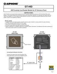
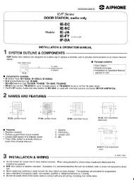
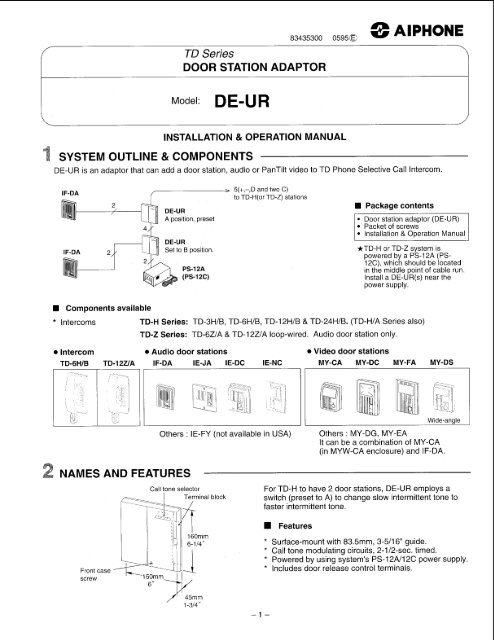
SYSTEM OUTLINE & COMPONENTS<br />
TD Series<br />
DOOR STATION ADAPTOR<br />
INSTALLATION & OPERATION MANUAL<br />
83435300 05950 AlPHONE<br />
<strong>DE</strong>-<strong>UR</strong> is an adaptor that can add a door station, audio or PanTilt video to TD Phone Selective Call Intercom.<br />
IF-DA<br />
@-<br />
IF-DA<br />
Components available<br />
* Intercoms<br />
A position, preset<br />
Set to B position<br />
5(+,-,D and two C)<br />
to TD-H(or TD-Z) stations<br />
Package contents<br />
Packet of screws<br />
Installation & Operation Manual<br />
*TD-H or TD-Z system is<br />
powered by a PS-12A (PS-<br />
12C), which should be located<br />
in the middle point of cable run.<br />
Install a <strong>DE</strong>-<strong>UR</strong>(s) near the<br />
power supply.<br />
TD-H Series: TD-3H/B, TD-6H/B, TD-I 2H/B & TD-24H/B. (TD-H/A Series also)<br />
TD-2 Series: TD-6Z/A & TD-I2Z/A loop-wired. Audio door station only.<br />
0 Intercom 0 Audio door stations 0 Video door stations<br />
TD-6HIB TD-12UA IF-DA<br />
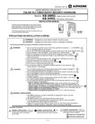
NAMES AND FEAT<strong>UR</strong>ES<br />
Front case<br />
screw<br />
Others : IE-FY (not available in USA) Others : MY-DG, MY-EA<br />
It can be a combination of MY-CA<br />
(in MYW-CA enclosure) and IF-DA.<br />
Call tone selector For TD-H to have 2 door stations, <strong>DE</strong>-<strong>UR</strong> employs a<br />
switch (preset to A) to change slow intermittent tone to<br />
faster intermittent tone.<br />
-1-<br />
Features<br />
* Surface-mount with 83.5mm, 3-5/16" guide.<br />
* Call tone modulating circuits, 2-1/2-sec. timed.<br />
* Powered by using system's PS-I 2N12C power supply.<br />
* Includes door release control terminals.
PRECAUTIONS ON INSTALLATION & WIRING<br />
A CAUTION<br />
* Do not connect any terminal on any unit to AC power lines.<br />
* Unplug all power supplies while making wiring connections on any audio and video equipment.<br />
* <strong>DE</strong>-<strong>UR</strong> is an adaptor for indoor installation only. Follow precautions as stated in the Manuals packed with<br />
TD-H and MY-CU monitor.<br />
* Locate <strong>DE</strong>-<strong>UR</strong> unit(s) closely to power supply PS-12A (PS-12C) of TD-H or TD-Z system, so as to be fed DC12V<br />
from it.<br />
* Wiring to EL-9S door release must run in a separate jacketed cable and apart from intercom wiring.<br />
Before installing <strong>DE</strong>-<strong>UR</strong>, the contents of this Manual must be thoroughly read and understood.<br />
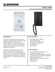
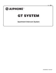
WIRING<br />
Terminal block layout<br />
+, -:<br />
1, 2:<br />
C:<br />
D:<br />
EL, EL:<br />
12V DC power<br />
Door station connection<br />
Selective communication from TD-H/TD-Z masters<br />
Call-in tone to TD-H masters (or TD-Z)<br />
Dry closure contact for door release<br />
<strong>DE</strong>-<strong>UR</strong> & power supp.: IocaLJn<br />
It is suggested to mount a <strong>DE</strong>-<strong>UR</strong> unit(s) in a recessed area, together with power supply PS-12A (PS-12C) and<br />
video adaptor, etc. Select a location that allows limited access only by qualified personnel, and is dust-free<br />
environment possible.<br />
EL-SS,<br />
AC trans.<br />
Audio door station<br />
k<br />
AC<br />
AC trans<br />
PanTilt video door station<br />
/- 4 to TD-H<br />
AC AC<br />
-2-<br />
camera<br />
AC trans<br />
2<br />
(r<br />
PanTilt doors plus 1 camera<br />
6 to MYH-CU<br />
5 to TD-H<br />
-<strong>UR</strong> PS-12Aor<br />
PS-12c<br />
AC AC
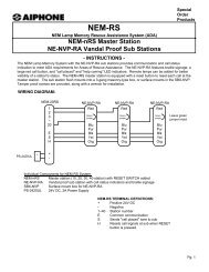
Wiring<br />
1. One audio IE/IF Series<br />
IF-DA<br />
PS-12A<br />
(PS-12C)<br />
<strong>DE</strong>-<strong>UR</strong><br />
'I<br />
4 wires to<br />
' to TD-H(TD-2)<br />
(max. 12)<br />
3. One PanTilt MY Series (plus one audio)<br />
-0 IF-0<br />
1-<br />
MY-DC<br />
MY-CU<br />
I I<br />
<strong>DE</strong>-<strong>UR</strong> PS-12A <strong>DE</strong>-<strong>UR</strong> TD-H<br />
(max. 12)<br />
(IF-DA)<br />
(for MY-DC)<br />
-3-<br />
2. Two audio IE/IF Series<br />
<strong>DE</strong>-<strong>UR</strong> <strong>DE</strong>-<strong>UR</strong><br />
IF-DA IF-DA 1 2<br />
PS-12A<br />
(PS-12C)<br />
4. Two PanTilt MY Series<br />
to PanTilt 1<br />
to PanTilt 2<br />
TO MY-Ck<br />
(camera<br />
PS-18D<br />
(door 1)<br />
Rp<br />
no 7<br />
2 7 <strong>DE</strong>-<strong>UR</strong> <strong>DE</strong>-<strong>UR</strong><br />
(door2) :E<br />
T<br />
5 wires to<br />
to TD-H(TD-2)<br />
4 I to TD-
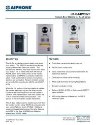
MOUNTING<br />
<strong>DE</strong>-<strong>UR</strong> chassis, after separated, mounts with<br />
83.5mm, 341 6" guide.<br />
1. Opening the cover, loosen the bottom screw.<br />
2. Lift front case off the prongs of chassis, and<br />
disconnect <strong>DE</strong>-<strong>UR</strong>.<br />
3. Mount the chassis to wall or board at 2 points.<br />
4. Make wire terminations for each door station,<br />
TD-H station, and PS-l2A(12C) power supply.<br />
5. Reconnect and mount <strong>DE</strong>-<strong>UR</strong> front case to<br />
chassis.<br />
<strong>DE</strong>-<strong>UR</strong><br />
From <strong>DE</strong>-<strong>UR</strong> to door station<br />
I Diameter<br />
Distance<br />
1 0.65mm I<br />
150m I<br />
0.8mm<br />
230m<br />
I 1 .Omm<br />
360m<br />
<strong>DE</strong>-<strong>UR</strong> <strong>DE</strong>-<strong>UR</strong><br />
Diameter<br />
Distance<br />
AWG<br />
Distance<br />
Pronas<br />
3<br />
83.5mm<br />
(3-5/16")<br />
-~<br />
_L<br />
-Chassis<br />
S P E C I F I CAT1 0 N S<br />
* Power source:<br />
DC 12V, supplied by a power supply PS-12A (PS-12C) of TD-H (TD-Z) system.<br />
* Current consumption: 120mA max.<br />
* Call tone:<br />
Intermittent tremolo, 2-1/2-timed<br />
* Wiring:<br />
* Wiring distance:<br />
Distance<br />
500' I 750' I 1,200'<br />
I To audio IE/IF door I 2 conductors laarallel) I<br />
1 To TD-H/B stations 1 4 conductors (D, C and + , -) 1<br />
I l l 1 }to TD-H<br />
* <strong>DE</strong>-<strong>UR</strong> EL, EL terminals capacity: DC 30V, 1A or AC 30V, 1A.<br />
* Dimensions: (H x W x D) 160 x 150 x 45 (mm). 6-1/4"H x 6"W x 1-3/4"D<br />
* Weight:<br />
320g (0.71 Ibs.) approx.<br />
<strong>Aiphone</strong> Co., Ltd., Nagoya, Japan<br />
<strong>Aiphone</strong> Corporation, Bellevue, WA, USA<br />
<strong>DE</strong>-<strong>UR</strong>-I(E) 0595E<br />
0.65mm 0.8mm 1 .Omm<br />
1 Om 15m 20m<br />
22AWG 20AWG 18AWG<br />
30' 50' 65'<br />
-4-<br />
T<br />
4 WARRANTY<br />
4<br />
4<br />
4 <strong>Aiphone</strong> warrants its products to be free from defects of material and workmanship under normal use and service for a period of one 4<br />
year after delivery %<br />
to the ultimate user and will repair free of charge or replace at no charge, should it become defective upon which 4<br />
4<br />
4 examination shall disclose to be defective and under warranty. <strong>Aiphone</strong> reserves unto itself the sole right to make the final decision 4<br />
whether there is a defect in materials and/or workmanship; and whether or not the product is within the warranty.<br />
4<br />
4<br />
4 This warranty shall not apply to any <strong>Aiphone</strong> product which has been subject to misuse, neglect, accident, or to use in violation of 4<br />
instructions furnished, nor extended to units which have been repaired or altered outside of the factory. This warranty does not cover 4<br />
$<br />
4<br />
4 batteries or damage caused by batteries used in connection with the product.<br />
4<br />
This warranty covers bench repairs only, and any repairs must be made at the shop or place designated in writing by <strong>Aiphone</strong>. 4<br />
4<br />
4 <strong>Aiphone</strong> will not be responsible for any costs incurred involving on site service calls.<br />
4<br />
4<br />
4<br />
4<br />
4<br />
4444444444444444444444444444444444444444444444444444444444444~ 44<br />
-4-<br />
g KlMU$fiOSKC<br />
HOME BUSINESS INDUSTRY<br />
Printed in Japan (E)