GT-0P2/0P3 Instructions - Aiphone
GT-0P2/0P3 Instructions - Aiphone
GT-0P2/0P3 Instructions - Aiphone

Create successful ePaper yourself
Turn your PDF publications into a flip-book with our unique Google optimized e-Paper software.
1 | <strong>GT</strong>-OP2 / <strong>GT</strong>-OP3 Installation <strong>Instructions</strong><br />
Installation <strong>Instructions</strong><br />
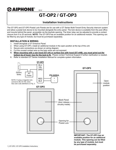
The <strong>GT</strong>-OP2 and <strong>GT</strong>-OP3 Postal Lock Panels are for use with a <strong>GT</strong> Series Multi-Tenant Entry Security intercom system<br />
and allow a postal lock device to be mounted alongside the entry panel. The lock device is available from the post office<br />
and mounts behind the panel, accessible via the keyhole opening. The timer relay can be adjusted to provide a contact<br />
closure from 5 to 20 seconds. NOTE: The <strong>GT</strong>-OP3 has an available position for an additional module. This opening can<br />
be filled by any type of module, but must be purchased separately.<br />
INSTALLATION & WIRING:<br />
1. Install alongside a <strong>GT</strong> Entrance Panel.<br />
2. When using <strong>GT</strong>-OP3, install an additional module in the open position at the top of the unit.<br />
3. Secure wire connections as shown on wiring diagram.<br />
4. Cut the unused contact wire so the bare wires are not exposed.<br />
5. When mounting with a rain hood (<strong>GT</strong>-nH) or surface box with hood (<strong>GT</strong>-nHB), you must grind out the<br />
bottom lip of hood / box for the lock to fit. Please contact Technical Support if further clarification is needed.<br />
6. Refer to standard <strong>GT</strong> Series Installation Manual for complete system information.<br />
Electric<br />
Strike<br />
AC<br />
Power<br />
NOTE: If using a magnetic lock,<br />
connect to BLU & YEL wires.<br />
See color code definitions on Pg. 2.<br />
0512<br />
<strong>GT</strong>-OP2<br />
BLU<br />
YEL<br />
ORG<br />
RED<br />
BLK<br />
<strong>GT</strong>-OP2<br />
PS-2420UL<br />
+<br />
-<br />
Blank Panel<br />
(door release<br />
circuitry inside)<br />
Opening for<br />
Postal Lock<br />
<strong>GT</strong>-OP3<br />
IMPORTANT: The <strong>GT</strong>-OP3 has an<br />
available position for an additional<br />
module. This opening can be filled<br />
by any type of module, but must<br />
be purchased separately.<br />
Open<br />
module<br />
position
WIRING DIAGRAM:<br />
PC Board can be adjusted up<br />
or down as needed to ensure<br />
proper contact from the postal<br />
lock to the switch<br />
GREEN*<br />
SWITCH (COMMON)<br />
WHITE*<br />
SWITCH (NORMALLY CLOSED)<br />
ORANGE<br />
RELAY NORMALLY OPEN CONTACT<br />
BLACK<br />
TO 24V DC (-)<br />
YELLOW<br />
RELAY NORMALLY CLOSED CONTACT<br />
BLUE<br />
RED<br />
RELAY COMMON CONTACT<br />
TO 24V DC (+)<br />
* The green and white wires bypass<br />
the timer circuit and go directly to the<br />
switch. Use this connection when<br />
going to a 3 rd party timer or when the<br />
timer circuit is not needed. The<br />
orange, black, yellow, blue, and red<br />
wires would not be used if you<br />
connect to the green / white bypass.<br />
SPECIFICATIONS:<br />
Power Source: 24V DC, powered by the PS-2420UL Power Supply<br />
Mounting: Flush mount or surface mount with <strong>GT</strong>-102HB for <strong>GT</strong>-OP2, <strong>GT</strong>-103HB for <strong>GT</strong>-OP3<br />
Terminations: Color-coded pre-wired pigtails<br />
Relay Input: 24V DC, Red, Black wires, 22AWG<br />
Relay Output: Blue (COM), Orange (N/O), Yellow (N/C) wires<br />
N/O Output rating: 5A at 30V DC<br />
10A at 125V AC<br />
3A at 250V AC<br />
N/C Ouptut rating: 3A at 30V DC or 125V AC<br />
Switch Output: Green (COM), White (N/C); Switch rated to 30V AC/DC, 1 amp<br />
Wiring: 2 conductors from 24V DC power supply to <strong>GT</strong>-OP panel<br />
2 conductors from <strong>GT</strong>-OP panel to strike, with power for strike wired in series<br />
Dimensions (HxWxD): <strong>GT</strong>-OP2: 8-7/8" x 5-5/16" x 2"<br />
<strong>GT</strong>-OP3: 12-5/8" x 5-5/16" x 2"<br />
2 | <strong>GT</strong>-OP2 / <strong>GT</strong>-OP3 Installation <strong>Instructions</strong><br />
<strong>GT</strong>-OP2 Rear View<br />
Timer control for door<br />
release (5 to 20 seconds)<br />
Switch, activated by<br />
postal lock device<br />
(When lock is engaged, the switch<br />
releases and starts timer)<br />
Lock device from Post<br />
Office installed here<br />
Opening for postal<br />
lock keyhole<br />
Lock device<br />
mounting studs<br />
Testing the unit without the postal lock:<br />
Tape or hold switch closed and apply power to the unit on Red / Black<br />
leads. Release switch and timer circuit will activate. Confirm relay<br />
activation with a multi-meter at the Blue / Yellow / Orange leads.<br />
IMPORTANT: If the Green and White wires are not used, cut wires to avoid a possible malfunction.<br />
<strong>Aiphone</strong> Corporation<br />
1700 130 th Ave NE Bellevue, WA 98005<br />
Ph: (800) 692-9200 Fax: (425) 455-0071<br />
tech@aiphone.com