Principles of Atomic rinciples Force Microscopy (AFM) - Mansic
Principles of Atomic rinciples Force Microscopy (AFM) - Mansic
Principles of Atomic rinciples Force Microscopy (AFM) - Mansic

Create successful ePaper yourself
Turn your PDF publications into a flip-book with our unique Google optimized e-Paper software.
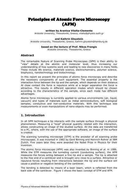
Abstract<br />
<strong>P<strong>rinciples</strong></strong> <strong>rinciples</strong> <strong>rinciples</strong> <strong>of</strong> <strong>of</strong> <strong>of</strong> <strong>Atomic</strong> <strong>Atomic</strong> <strong>Force</strong> <strong>Force</strong> <strong>Microscopy</strong><br />
<strong>Microscopy</strong><br />
(<strong>AFM</strong>)<br />
(<strong>AFM</strong>)<br />
written by Arantxa Vilalta-Clemente<br />
Aristotle University, Thessaloniki, Greece, vilalta@physics.auth.gr<br />
and Kathrin Gloystein<br />
Aristotle University, Thessaloniki, Greece, kathrin.gloystein@hamburg.de<br />
based on the lecture <strong>of</strong> Pr<strong>of</strong>. Nikos Frangis<br />
Aristotle University, Thessaloniki, Greece<br />
The remarkable feature <strong>of</strong> Scanning Probe Microscopes (SPM) is their ability to<br />
“view” details at the atomic and molecular level, thus increasing our<br />
understanding <strong>of</strong> how systems work and leading to new discoveries in many fields.<br />
These include life science, materials science, electrochemistry, polymer science,<br />
biophysics, nanotechnology and biotechnology.<br />
In this report we present the p<strong>rinciples</strong> <strong>of</strong> atomic force microscopy and describe<br />
the necessary components <strong>of</strong> such equipment. The essential property is the<br />
interaction force between the tip and the sample, which depends on their distance.<br />
At close contact the force is repulsive while at a larger separation the force is<br />
attractive. This results in different operation modes which should be chosen<br />
according to the characteristics <strong>of</strong> the sample, since each mode has different<br />
advantages.<br />
<strong>Atomic</strong> force microscopy is currently applied to various environments (air, liquid,<br />
vacuum) and types <strong>of</strong> materials such as metal semiconductors, s<strong>of</strong>t biological<br />
samples, conductive and non-conductive materials. With this technique size<br />
measurements or even manipulations <strong>of</strong> nano-objects may be performed.<br />
1. Introduction<br />
In all SPM techniques a tip interacts with the sample surface through a physical<br />
phenomenon. Measuring a “local” physical quantity related with the interaction,<br />
allows constructing an image <strong>of</strong> the studied surface. All the data are transferred<br />
to a PC, where, with the use <strong>of</strong> the appropriate s<strong>of</strong>tware, an image <strong>of</strong> the surface<br />
is created.<br />
The scanning tunneling microscope (STM) is the ancestor <strong>of</strong> all scanning probe<br />
microscopes. It was invented in 1982 by Gerd Binning and Heinrich Rohrer at IBM<br />
Zurich. Five years later they were awarded the Nobel Prize in Physics for their<br />
invention.<br />
The atomic force microscope (<strong>AFM</strong>) was also invented by Binning et al. in 1986.<br />
While the STM measures the tunneling current (conducting surface), the <strong>AFM</strong><br />
measures the forces acting between a fine tip and a sample. The tip is attached<br />
to the free end <strong>of</strong> a cantilever and is brought very close to a surface. Attractive or<br />
repulsive forces resulting from interactions between the tip and the surface will<br />
cause a positive or negative bending <strong>of</strong> the cantilever.<br />
The bending is detected by means <strong>of</strong> a laser beam, which is reflected from the<br />
back side <strong>of</strong> the cantilever. Figure 1 shows the basic concept <strong>of</strong> STM and <strong>AFM</strong>.<br />
Physics <strong>of</strong> Advanced Materials Winter School 2008 1
Figure 1. Principle <strong>of</strong> STM (left) and <strong>AFM</strong> (right).<br />
2. Components <strong>of</strong> the microscope<br />
2.1. Piezocrystals<br />
Piezocrystals are ceramic materials that expand or contract in the presence <strong>of</strong><br />
voltage gradient and conversely, they develop an electrical potential in response<br />
to mechanical pressure. In this way, movements in x, y and z direction are<br />
possible.<br />
2.2. Probe<br />
The probe represents a micromachined cantilever with a sharp tip at one end,<br />
which is brought into interaction with the sample surface.<br />
Each probe has different specifications and shape. V-shaped cantilevers are the<br />
most popular (but also there are rectangular), providing low mechanical<br />
resistance to vertical deflection, and high resistance to lateral torsion. Cantilevers<br />
typically range from 100 to 200 µm in length (l), 10 to 40 µm in width (w), and<br />
0.3 to 2µm in thickness (t).<br />
Figure 2. Dimensions <strong>of</strong> the cantilever.<br />
Integrated cantilevers are usually made from silicon (Si) or silicon nitride (Si3N4).<br />
They are characterized by their force constant and resonant frequency, which<br />
have to be chosen according to the sample to be studied.<br />
Additionally an optical detection system and electronics for the management <strong>of</strong><br />
scanning procedures and data acquisition are necessary.<br />
Physics <strong>of</strong> Advanced Materials Winter School 2008 2
3. Beam Deflection Detection<br />
To detect the displacement <strong>of</strong> the cantilever, a laser is reflected <strong>of</strong>f the back <strong>of</strong><br />
the cantilever and collected in a photodiode. The diode is divided into four parts,<br />
as seen in Figure 3. When the laser is displaced vertically along the positions top<br />
(B-A) and bottom (D-C), there exists a bending due to topography, while if this<br />
movement is horizontal left (B-D) and right (A-C), it produces a torsion due to<br />
“friction” (lateral force).<br />
Figure 3. The scanned cantilever/tip system.<br />
3. <strong>Force</strong>s versus distance curve<br />
A force sensor in an <strong>AFM</strong> can only work if the probe interacts with the force field<br />
associated with a surface. The dependence <strong>of</strong> the van der Waals force upon the<br />
distance between the tip and the sample is shown in Figure 4.<br />
V(r)<br />
Con tact mode<br />
Repulsive Region<br />
Non -con tact<br />
mode<br />
Attractive Region<br />
Figure 4. Potential energy diagram <strong>of</strong> a probe and sample.<br />
In the contact regime, the cantilever is held less than a few angstroms from the<br />
sample surface, and the interatomic force between the cantilever and the sample<br />
is repulsive. In the non-contact regime, the cantilever is held on the order <strong>of</strong> tens<br />
to hundreds <strong>of</strong> angstroms from the sample surface, and the interatomic force<br />
between the cantilever and sample is attractive (largely a result <strong>of</strong> the long-range<br />
Van der Waals interactions).<br />
Physics <strong>of</strong> Advanced Materials Winter School 2008 3<br />
r
Attractive forces near the surface are caused by a nanoscopic layer <strong>of</strong><br />
contamination that is present on all surfaces in ambient air. The amount <strong>of</strong><br />
contamination depends on the environment in which the microscope is being<br />
operated. Repulsive forces increase as the probe begins to contact the surface.<br />
The repulsive forces in the <strong>AFM</strong> tend to cause the cantilever to bend up.<br />
In figure 5 an experimental force vs. distance curve is shown. It corresponds to<br />
one cycle <strong>of</strong> the tip approaching to, getting into contact and separating from the<br />
sample.<br />
Figure 5. Experimental force vs. distance curve.<br />
At the right side <strong>of</strong> the curve, the scanner is fully retracted and the cantilever is<br />
undeflected since the tip is not touching the sample (region I). As the scanner<br />
extends, the cantilever remains undeflected until it comes close enough to the<br />
sample surface for the tip to experience the attractive van der Waals force. In the<br />
point II, the cantilever suddenly bends slightly towards the surface. As the<br />
scanner continues to extend, the cantilever deflects away from the surface,<br />
approximately linearly (region III, red color). After full extension, at the extreme<br />
left <strong>of</strong> the plot (region III, black color), the scanner begins to retract. The<br />
cantilever deflection retraces the same curve. In the point (IV), the scanner<br />
retracts enough that the tip springs free.<br />
The resolution for <strong>AFM</strong> instruments is: a) 0.1 nm on sample plane (x, y) for hard<br />
and flat surfaces and 0.7-5 nm for s<strong>of</strong>t materials (polymers and biological<br />
samples), b) 0.01 nm for z axis.<br />
4. Modes <strong>of</strong> operation<br />
4.1. Contact Mode<br />
In the so-called contact-<strong>AFM</strong> mode, the tip makes s<strong>of</strong>t “physical contact” with the<br />
surface <strong>of</strong> the sample. The deflection <strong>of</strong> the cantilever ∆x is proportional to the<br />
force acting on the tip, via Hook’s law, F=-k ∆x, where k is the spring constant <strong>of</strong><br />
the cantilever. In contact-mode the tip either scans at a constant small height<br />
above the surface or under the conditions <strong>of</strong> a constant force. In the constant<br />
height mode the height <strong>of</strong> the tip is fixed, whereas in the constant-force mode the<br />
deflection <strong>of</strong> the cantilever is fixed and the motion <strong>of</strong> the scanner in z-direction is<br />
recorded. By using contact-mode <strong>AFM</strong>, even “atomic resolution” images are<br />
obtained.<br />
Physics <strong>of</strong> Advanced Materials Winter School 2008 4
For contact mode <strong>AFM</strong> imaging, it is necessary to have a cantilever which is s<strong>of</strong>t<br />
enough to be deflected by very small forces and has a high enough resonant<br />
frequency to not be susceptible to vibrational instabilities. Silicon Nitride tips are<br />
used for contact mode. In these tips, there are 4 cantilever with different<br />
geometries attached to each substrate, resulting in 4 different spring constants<br />
(Figure 6).<br />
Figure 6. Probe with four different cantilevers with different spring constants (N/m).<br />
To avoid problems caused by capillary forces which are generated by a liquid<br />
contamination layer usually present on surfaces in air, the sample can be studied<br />
while immersed in a liquid. This procedure is especially beneficial for biological<br />
samples.<br />
4.2. Non Contact Mode<br />
In this mode, the probe operates in the attractive force region and the tip-sample<br />
interaction is minimized. The use <strong>of</strong> non-contact mode allowed scanning without<br />
influencing the shape <strong>of</strong> the sample by the tip-sample forces. In most cases, the<br />
cantilever <strong>of</strong> choice for this mode is the one having high spring constant <strong>of</strong> 20-<br />
100 N/m so that it does not stick to the sample surface at small amplitudes. The<br />
tips mainly used for this mode are silicon probes.<br />
4.3. Tapping Mode (intermittent contact Mode)<br />
The force measured by <strong>AFM</strong> can be classified into long-range forces and shortrange<br />
forces. The first class dominates when we scan at large distances from the<br />
surface and they can be Van der Waals force, capillary forces (due to the water<br />
layer <strong>of</strong>ten present in an ambient environment). When the scanning is in contact<br />
with the surface the short range forces are very important, in particular the<br />
quantum mechanical forces (Pauli Exclusion Principle forces).<br />
In tapping mode-<strong>AFM</strong> the cantilever is oscillating close to its resonance frequency.<br />
An electronic feedback loop ensures that the oscillation amplitude remains<br />
constant, such that a constant tip-sample interaction is maintained during<br />
scanning.<br />
<strong>Force</strong>s that act between the sample and the tip will not only cause a change in<br />
the oscillation amplitude, but also change in the resonant frequency and phase <strong>of</strong><br />
the cantilever. The amplitude is used for the feedback and the vertical<br />
adjustments <strong>of</strong> the piezoscanner are recorded as a height image. Simultaneously,<br />
the phase changes are presented in the phase image (topography).<br />
The advantages <strong>of</strong> the tapping mode are the elimination <strong>of</strong> a large part <strong>of</strong><br />
permanent shearing forces and the causing <strong>of</strong> less damage to the sample surface,<br />
even with stiffer probes. Different components <strong>of</strong> the sample which exhibit<br />
difference adhesive and mechanical properties will show a phase contrast and<br />
therefore even allow a compositional analysis. For a good phase contrast, larger<br />
tip forces are <strong>of</strong> advantage, while minimization <strong>of</strong> this force reduces the contact<br />
area and facilitates high-resolution imaging. So in applications it is necessary to<br />
choose the right values matching the objectives. Silicon probes are used primarily<br />
for Tapping Mode applications.<br />
Physics <strong>of</strong> Advanced Materials Winter School 2008 5
Table 1 is a summary <strong>of</strong> the main characteristics <strong>of</strong> the three modes explained<br />
before. In these modes we can work in different environments: air, liquid and<br />
vacuum. In contact mode the tip touches the sample surface, which leads to a<br />
high force and allows manipulation <strong>of</strong> the sample. The disadvantage is that the<br />
<strong>AFM</strong> tip may be contaminated by the sample. The opposite happens in the noncontact<br />
mode, where the tip stays at a distance above the sample. In tapping<br />
mode the tip touches the surface periodically therefore manipulation <strong>of</strong> the<br />
sample, as well as contamination <strong>of</strong> the tip is possible.<br />
Table 1. Properties <strong>of</strong> the different operation modes in <strong>AFM</strong>.<br />
Operation mode<br />
Contact<br />
mode<br />
Non-contact<br />
mode<br />
Tapping<br />
mode<br />
tip loading force low → high low low<br />
contact with sample<br />
surface<br />
yes no periodical<br />
manipulation <strong>of</strong> sample yes no yes<br />
contamination <strong>of</strong> <strong>AFM</strong> tip yes no yes<br />
4.4. Advantages and Disadvantages <strong>of</strong> <strong>AFM</strong> Modes<br />
Contact Mode <strong>AFM</strong><br />
Advantages:<br />
- High scan speeds.<br />
- “<strong>Atomic</strong> resolution” is possible.<br />
- Easier scanning <strong>of</strong> rough samples with extreme changes in vertical<br />
topography.<br />
Disadvantages:<br />
- Lateral forces can distort the image.<br />
- Capillary forces from a fluid layer can cause large forces normal to the tipsample<br />
interaction.<br />
- Combination <strong>of</strong> these forces reduces spatial resolution and can cause<br />
damage to s<strong>of</strong>t samples.<br />
Non-contact Mode <strong>AFM</strong><br />
Advantage:<br />
- Low force is exerted on the sample surface and no damage is caused to<br />
s<strong>of</strong>t samples<br />
Disadvantages:<br />
- Lower lateral resolution, limited by tip-sample separation.<br />
- Slower scan speed to avoid contact with fluid layer.<br />
- Usually only applicable in extremely hydrophobic samples with a minimal<br />
fluid layer.<br />
Physics <strong>of</strong> Advanced Materials Winter School 2008 6
Tappping Mode <strong>AFM</strong><br />
Advantages:<br />
- Higher lateral resolution (1 nm to 5 nm).<br />
- Lower forces and less damage to s<strong>of</strong>t samples in air.<br />
- Almost no lateral forces.<br />
Disadvantage:<br />
- Slower scan speed than in contact mode.<br />
5. <strong>AFM</strong> images<br />
The tip <strong>of</strong> the <strong>AFM</strong> is used:<br />
- for imaging.<br />
- for measuring forces (and mechanical properties) at the nanoscale.<br />
- as a nanoscale tool, i.e. for bending, cutting and extracting s<strong>of</strong>t materials<br />
(such as Polymers, DNA, and nanotubes), at the submicron scale under<br />
hight-resolution image control.<br />
Figures 7-11 show different examples <strong>of</strong> <strong>AFM</strong> images taken by the modes<br />
explained before. The samples can be various materials, like semiconductors,<br />
biological material or polymer films. The last picture shows two cases <strong>of</strong> samplemanipulation.<br />
Figure 7. Three-dimensional <strong>AFM</strong> images from three different types <strong>of</strong> Pd samples,<br />
grown on 6H-SiC.<br />
Physics <strong>of</strong> Advanced Materials Winter School 2008 7
Figure 8. Tapping Mode image <strong>of</strong> biological sample, in this case nucleosomal DNA.<br />
a)<br />
Figure 9. Non-contact mode <strong>of</strong> titanium nitride grains, a) scanner 10 µm and b) 5 µm.<br />
Figure 10. Tapping Mode image <strong>of</strong> poly(styrene) and poly(methyl methacrylate) blend<br />
polymer film. The surface structure is resulted from the spinodal decomposition.<br />
Scanner 3 µm.<br />
Physics <strong>of</strong> Advanced Materials Winter School 2008 8<br />
b)
Figure 11.<br />
Left image: Manipulation <strong>of</strong> a nanotube on a silicon substrate. The <strong>AFM</strong> tip is<br />
used to create the Greek letter "theta" from a 2.5 micron long nanotube.<br />
Right image: A single nanotube (in red) originally on an insulating substrate<br />
(SiO2, shown in green) is manipulated in a number <strong>of</strong> steps onto a tungsten film<br />
thin wire (in blue), and finally is stretched across an insulating tungsten oxide<br />
barrier (in yellow).<br />
6. Applications<br />
The number <strong>of</strong> applications for <strong>AFM</strong> has exploded since it was invented in 1986<br />
and nowadays this technique is involved in many fields <strong>of</strong> nanoscience and<br />
nanotechnology. The remarkable feature <strong>of</strong> STM and <strong>AFM</strong> instruments is their<br />
ability to examine samples not only in an ultrahigh vacuum but also at ambient<br />
conditions or even in liquids.<br />
One <strong>of</strong> the advantages <strong>of</strong> <strong>AFM</strong> is that it can image the non-conducting surfaces,<br />
and therefore it is very suitable for biological systems.<br />
The <strong>AFM</strong> is capable <strong>of</strong> measuring nanometer scale images <strong>of</strong> insulating surfaces<br />
with little or no sample preparation as well as measuring three dimensional<br />
images <strong>of</strong> surfaces and studying the topography.<br />
Some possible applications <strong>of</strong> <strong>AFM</strong> are:<br />
- Substrate roughness analysis.<br />
- Step formation in thin film epitaxial deposition.<br />
- Pin-holes formation or other defects in oxides growth.<br />
- Grain size analysis.<br />
- Phase mode is very sensitive to variations in material properties, including<br />
surface stiffness, elasticity and adhesion.<br />
- Comparing the tip-samples forces curves for materials to study the ratio <strong>of</strong><br />
Young´s Modulus (graphite as a reference for measure <strong>of</strong> the indentation).<br />
- Obtaining information <strong>of</strong> what is happening under indentation at very small<br />
loads.<br />
- By In situ <strong>AFM</strong> analysis with changes in temperature we can study changes in<br />
the structure.<br />
Physics <strong>of</strong> Advanced Materials Winter School 2008 9
7. References<br />
[1] G. Binning, C. F. Quate, Ch. Gerber. <strong>Atomic</strong> force microscope. Phys. Rev.<br />
Lett. 56 (9), (1986) 930.<br />
[2] Park Scientific Instruments. A practical guide to scanning probe<br />
microscopy. (1997).<br />
[3] N. Yao, Z. L. Wang. Handbook <strong>of</strong> <strong>Microscopy</strong> for Nanotechnology.<br />
(2005).<br />
[4] Veeco. Scanning Probe <strong>Microscopy</strong> Training Notebook. Version 3.0.<br />
(2000).<br />
[5] http://www.research.ibm.com.<br />
Physics <strong>of</strong> Advanced Materials Winter School 2008 10