The Röntgen Radiation and its application in studies of ... - Mansic
The Röntgen Radiation and its application in studies of ... - Mansic
The Röntgen Radiation and its application in studies of ... - Mansic

You also want an ePaper? Increase the reach of your titles
YUMPU automatically turns print PDFs into web optimized ePapers that Google loves.
<strong>The</strong> <strong>Röntgen</strong> <strong>Radiation</strong> <strong>and</strong> <strong>its</strong> <strong>application</strong> <strong>in</strong><br />
<strong>studies</strong> <strong>of</strong> advanced materials<br />
written by Mihaela Alex<strong>and</strong>ru<br />
“Petru Poni” Institute <strong>of</strong> Macromolecular Chemistry, Iasi, Romania,aleaahim@yahoo.com<br />
Abstract<br />
<strong>and</strong> Alex<strong>and</strong>ra Nistor<br />
“Gh. Asachi” Technical University Iasi, Romania, anistor@ch.tuiasi.ro<br />
based on the lecture <strong>of</strong> Pr<strong>of</strong>. Tomasz Goryczka<br />
University <strong>of</strong> Silesia, Pol<strong>and</strong>, goryczka@us.edu.pl<br />
<strong>The</strong> wave-particle dual nature <strong>of</strong> the electromagnetic radiation was emphasized<br />
through the discovery <strong>of</strong> X-rays. <strong>The</strong> X-rays are, posses the same nature as light<br />
has, electromagnetic waves, but <strong>in</strong> comparison to the light rays, the X radiation<br />
has a much higher frequency. Accord<strong>in</strong>g to Planck’s formula, the energy <strong>of</strong> X<br />
photon is correspond<strong>in</strong>gly higher. It expla<strong>in</strong>s why properties <strong>of</strong> the X radiations<br />
manifest more evidently <strong>in</strong> comparison to those <strong>of</strong> the light. On this occasion<br />
another important particle-like property <strong>of</strong> the photon will be highlighted <strong>and</strong> that<br />
is the impulse.<br />
1. Introduction<br />
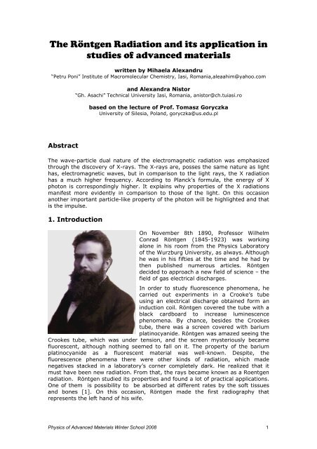
On November 8th 1890, Pr<strong>of</strong>essor Wilhelm<br />
Conrad <strong>Röntgen</strong> (1845-1923) was work<strong>in</strong>g<br />
alone <strong>in</strong> his room from the Physics Laboratory<br />
<strong>of</strong> the Wurzburg University, as always. Although<br />
he was <strong>in</strong> his fifties at the time <strong>and</strong> he had by<br />
then published numerous articles. <strong>Röntgen</strong><br />
decided to approach a new field <strong>of</strong> science – the<br />
field <strong>of</strong> gas electrical discharges.<br />
In order to study fluorescence phenomena, he<br />
carried out experiments <strong>in</strong> a Crooke’s tube<br />
us<strong>in</strong>g an electrical discharge obta<strong>in</strong>ed form an<br />
<strong>in</strong>duction coil. <strong>Röntgen</strong> covered the tube with a<br />
black cardboard to <strong>in</strong>crease lum<strong>in</strong>escence<br />
phenomena. By chance, besides the Crookes<br />
tube, there was a screen covered with barium<br />
plat<strong>in</strong>ocyanide. <strong>Röntgen</strong> was amazed see<strong>in</strong>g the<br />
Crookes tube, which was under tension, <strong>and</strong> the screen mysteriously became<br />
fluorescent, although noth<strong>in</strong>g seemed to fall on it. <strong>The</strong> property <strong>of</strong> the barium<br />
plat<strong>in</strong>ocyanide as a fluorescent material was well-known. Despite, the<br />
fluorescence phenomena there were other k<strong>in</strong>ds <strong>of</strong> radiation, which made<br />
negatives stacked <strong>in</strong> a laboratory’s corner completely dark. He realized that it<br />
must have been new radiation. From that, the rays became known as a Roentgen<br />
radiation. <strong>Röntgen</strong> studied <strong>its</strong> properties <strong>and</strong> found a lot <strong>of</strong> practical <strong>application</strong>s.<br />
One <strong>of</strong> them is possibility to be absorbed at different rates by the s<strong>of</strong>t tissues<br />
<strong>and</strong> bones [1]. On this occasion, <strong>Röntgen</strong> made the first radiography that<br />
represents the left h<strong>and</strong> <strong>of</strong> his wife.<br />
Physics <strong>of</strong> Advanced Materials W<strong>in</strong>ter School 2008 1
In this radiography the h<strong>and</strong> bones show up very obvious, just as the r<strong>in</strong>g that<br />
his wife was wear<strong>in</strong>g on her f<strong>in</strong>ger. On the day <strong>of</strong> March 28th 1895, <strong>Röntgen</strong><br />
presented his results to the Medical-Physical Society from Wurzburg. In the<br />
course <strong>of</strong> a few days, the experiments <strong>of</strong> <strong>Röntgen</strong> were repeated <strong>in</strong> numerous<br />
laboratories around the world <strong>and</strong> after a few weeks attempts were made to use<br />
the X rays <strong>in</strong> medic<strong>in</strong>e. After a couple <strong>of</strong> months from the discovery <strong>of</strong> X-rays, the<br />
Romanian physicist Dragomir Hurmuzescu (1865-1954) built a very sensitive<br />
electroscope, that was named after him, especially for the study <strong>of</strong> these<br />
radiations. This electroscope has proved to be very useful for the study <strong>of</strong><br />
ionisation phenomenons caused by different radioactive substances. <strong>Röntgen</strong>’s<br />
discovery became famous <strong>in</strong> a very short time.<br />
Almost all scientific journals were preoccupied on it. Indeed what could be more<br />
amaz<strong>in</strong>g than <strong>its</strong> <strong>in</strong>visibility for the human eye? Such property can be used to<br />
“see” the skeleton <strong>of</strong> a human body <strong>and</strong> other animals. Of course, one cannot<br />
deny that <strong>Röntgen</strong> had a struck <strong>of</strong> luck when he discovered the X rays. Other<br />
physicists have had a chance, but they didn’t know how to take advantage <strong>of</strong> that.<br />
In the book “<strong>The</strong> History <strong>of</strong> the Ether <strong>and</strong> <strong>of</strong> the Matter <strong>The</strong>ories”, Whittaker tells<br />
<strong>of</strong> a physicist from Oxford who had realized that a latent image forms on the<br />
photographic plates only when they are close to a gas discharge tube. He found<br />
that X-rays are emitted by the part <strong>of</strong> a tube which is bombarded by electrons<br />
obta<strong>in</strong>ed from a cathode. Based on this observation, <strong>Röntgen</strong> built a generator<br />
<strong>and</strong> the tube, which provides the most favorable way for obta<strong>in</strong><strong>in</strong>g <strong>and</strong> us<strong>in</strong>g<br />
X - rays. <strong>Röntgen</strong> knew that cathode rays leave the cathode along a normalised<br />
direction Based on this he built a concave cathode that focused the emitted beam<br />
<strong>in</strong> one po<strong>in</strong>t. Because most <strong>of</strong> the energy brought by cathode rays turn <strong>in</strong>to a<br />
heat strongly <strong>in</strong>creas<strong>in</strong>g temperature <strong>of</strong> the anode, present<strong>in</strong>g even the danger <strong>of</strong><br />
melt<strong>in</strong>g it, <strong>Röntgen</strong> <strong>in</strong>troduced <strong>in</strong> the tube a special plate made from heat<br />
resistant material, on which he focused the beam.<br />
This plate, that was given the name <strong>of</strong> anticathode, was placed at an angle <strong>of</strong> 45º<br />
from the axle <strong>of</strong> the tube <strong>in</strong> order to make the use <strong>of</strong> the emitted X-rays more<br />
comfortable. This way, <strong>Röntgen</strong> built the tube that bears his name <strong>and</strong> which<br />
construction rema<strong>in</strong>ed essentially unchanged until today.<br />
Physics <strong>of</strong> Advanced Materials W<strong>in</strong>ter School 2008 2
<strong>The</strong> next improvement was <strong>in</strong>troduced by William David Coolidge <strong>in</strong> 1913. He<br />
<strong>in</strong>vented the X-ray tube with heated cathode. <strong>The</strong> tube is vacuumed <strong>and</strong> the<br />
cathode em<strong>its</strong> electrons through the heat<strong>in</strong>g with an auxiliary electric current.<br />
<strong>The</strong> cause <strong>of</strong> the electrons emission is not the bombardment with electrons as it<br />
was <strong>in</strong> the previous cases. <strong>The</strong> acceleration <strong>of</strong> the electrons emission process is<br />
done by apply<strong>in</strong>g a high tension electric current, through the tube. When the<br />
voltage <strong>in</strong>creases, the wavelength <strong>of</strong> the radiation decreases.<br />
<strong>The</strong> American physicist Arthur Holly Compton (1892 - 1962), a Nobel Prize w<strong>in</strong>ner,<br />
discovered through his <strong>studies</strong> the so-called Compton Effect <strong>in</strong> the year 1922. His<br />
theory demonstrates that the wavelengths <strong>of</strong> the X <strong>and</strong> gamma radiations<br />
<strong>in</strong>crease. This phenomenon also proves the particle-like nature <strong>of</strong> the X rays.<br />
In 1913, physicists: Sir W. H. Bragg <strong>and</strong> his son Sir W.L. Bragg developed a<br />
formula, which expla<strong>in</strong>s diffraction effect when crystals reflects X-ray beams at a<br />
certa<strong>in</strong> <strong>in</strong>cidence angle (theta, θ). Now it is known as Bragg’s Law:<br />
2 ⋅ d hkl ⋅ s<strong>in</strong>θ<br />
= n ⋅ λ<br />
⋅ λ<br />
=<br />
2 ⋅s<strong>in</strong>θ<br />
n<br />
d<br />
<strong>The</strong> variable d is an <strong>in</strong>terplanar distance between atomic layers <strong>in</strong> a crystal, <strong>and</strong><br />
λ is the wavelength <strong>of</strong> the X-ray beam; n is an <strong>in</strong>teger. This observation is an<br />
example <strong>of</strong> X-ray wave <strong>in</strong>terference, commonly known as X-ray diffraction (XRD),<br />
<strong>and</strong> was direct evidence for the periodic atomic structure <strong>of</strong> crystals postulated<br />
for several centuries.<br />
<strong>The</strong> Braggs were awarded the Nobel Prize <strong>in</strong> physics <strong>in</strong> 1915 for their work <strong>in</strong><br />
determ<strong>in</strong><strong>in</strong>g crystal structures beg<strong>in</strong>n<strong>in</strong>g with NaCl, ZnS <strong>and</strong> diamond. Although<br />
Physics <strong>of</strong> Advanced Materials W<strong>in</strong>ter School 2008 3
Bragg’s Law was used to expla<strong>in</strong> the <strong>in</strong>terference pattern <strong>of</strong> X-rays scattered by<br />
crystals, diffraction has been developed to study the structure <strong>of</strong> all states <strong>of</strong><br />
matter with any beam, e.g., ions, electrons, neutrons, <strong>and</strong> protons, with a<br />
wavelength comparable to the distance between the atomic or molecular<br />
structure.<br />
Bragg’s Law: n ⋅ λ = 2 ⋅ d ⋅ s<strong>in</strong>θ<br />
Figure 1. <strong>The</strong> reflection <strong>of</strong> the X-rays on the crystal planes<br />
Constructive <strong>in</strong>terference occurs only when difference <strong>of</strong> between rays is<br />
proportional to the wavelength:<br />
n ⋅ λ = AB + BC<br />
AB=BC<br />
n ⋅ λ = 2 ⋅ AB<br />
s<strong>in</strong> θ = AB / d<br />
AB = d ⋅ s<strong>in</strong>θ<br />
n ⋅ = 2 ⋅ d ⋅<br />
λ s<strong>in</strong>θ<br />
λ = 2 ⋅ d ⋅ s<strong>in</strong>θ<br />
hkl<br />
P.P. Ewald published <strong>in</strong> 1916 a more simple <strong>and</strong> more elegant theory <strong>of</strong> the Xray<br />
diffraction, by <strong>in</strong>troduc<strong>in</strong>g the concept <strong>of</strong> reciprocal network. Comparison <strong>of</strong><br />
Bragg’s Law (left), Bragg Modified Law (middle) <strong>and</strong> Ewald Law (right):<br />
⋅ λ<br />
=<br />
2 ⋅s<strong>in</strong>θ<br />
n<br />
d<br />
Physics <strong>of</strong> Advanced Materials W<strong>in</strong>ter School 2008 4<br />
hkl<br />
1/<br />
d<br />
s<strong>in</strong>θ<br />
=<br />
2 / λ<br />
σ<br />
s<strong>in</strong>θ<br />
=<br />
1<br />
2 ⋅<br />
λ
2. <strong>The</strong> production <strong>of</strong> X-rays<br />
<strong>The</strong> X rays, that are currently be<strong>in</strong>g used for different purposes, can be obta<strong>in</strong>ed<br />
with help <strong>of</strong> the X-ray tube. <strong>The</strong> X-ray tube is a vacuumed space (10 -6 torr) <strong>in</strong>side<br />
<strong>of</strong> which there are two electrodes, a hot cathode (tungsten filament) <strong>and</strong> an<br />
anode between which a 10 ÷ 200 kV voltage is applied. <strong>The</strong> electrons emitted by<br />
the filament are accelerated due to the voltage differential <strong>and</strong> when they hit the<br />
anode X radiation is emitted. Because through the collision with the anode over<br />
98% from the energy <strong>of</strong> <strong>in</strong>com<strong>in</strong>g electrons is turned <strong>in</strong>to heat (the rest consist <strong>of</strong><br />
energy radiated as X-rays), the anode has to be water cooled (Figure 2) [2]. For<br />
higher power (5 ÷ 60 kW) <strong>of</strong> X-ray radiation, the tube equipped with rotat<strong>in</strong>g<br />
anode is <strong>in</strong> use. On the X-ray tube used for structural <strong>studies</strong>, the electrons<br />
emitted by the filament are focused, only on a rectangular surface <strong>of</strong> the anode<br />
(tubes with Gotze l<strong>in</strong>ear focal po<strong>in</strong>t).<br />
Figure 2. <strong>The</strong> scheme <strong>of</strong> the tube with rotat<strong>in</strong>g anode<br />
Figure 3. <strong>The</strong> pr<strong>in</strong>ciple <strong>of</strong> X-ray diffraction [3]<br />
3. X-ray spectrum - cont<strong>in</strong>uous <strong>and</strong> characteristic<br />
Roentgen radiation, produced with the help <strong>of</strong> X-ray tubes, is the result <strong>of</strong> the<br />
accelerated electrons <strong>in</strong>teraction with the atoms from surface <strong>of</strong> the anode. <strong>The</strong>re<br />
are two types <strong>of</strong> <strong>in</strong>teractions that lead to the apparition <strong>of</strong> a cont<strong>in</strong>uous spectrum<br />
or a characteristic spectrum [4].<br />
a. <strong>The</strong> cont<strong>in</strong>uous spectrum. An electron that moves at a high speed can be<br />
decelerated when pass near <strong>of</strong> atom nuclei. As a result <strong>of</strong> this <strong>in</strong>teraction the<br />
Physics <strong>of</strong> Advanced Materials W<strong>in</strong>ter School 2008 5
k<strong>in</strong>etic energy <strong>of</strong> the electron is transformed totally or partially, <strong>in</strong>to a photon <strong>of</strong><br />
X-ray, with <strong>its</strong> frequency ν given by E<strong>in</strong>ste<strong>in</strong>’s equation:<br />
2 2 ( v − v ) = ⋅ϑ<br />
⎛ m ⎞<br />
∆E = ⎜ ⎟ ⋅ 1 2 h<br />
⎝ 2 ⎠<br />
b. <strong>The</strong> characteristic spectrum. Another type <strong>of</strong> <strong>in</strong>teraction <strong>of</strong> the accelerated<br />
electron with an atom could result <strong>in</strong> the expulsion <strong>of</strong> an electron from the<br />
<strong>in</strong>terior electronic orb<strong>its</strong> <strong>of</strong> the target atom <strong>and</strong> then the atom rema<strong>in</strong>s <strong>in</strong> an<br />
excited, ionized state. In order to come back to the normal state the jump <strong>of</strong> one<br />
electron from higher orbital is needed. Excess <strong>of</strong> energy is emitted as a photon <strong>of</strong> X-ray<br />
whit constant value <strong>of</strong> the wavelength.<br />
X-ray diffraction is used for:<br />
• Measur<strong>in</strong>g the average spac<strong>in</strong>g between crystallographic pla<strong>in</strong>s<br />
• Determ<strong>in</strong>ation <strong>of</strong> the orientation <strong>of</strong> a s<strong>in</strong>gle crystal or gra<strong>in</strong><br />
• Quantitative <strong>and</strong> qualitative phase analysis<br />
• F<strong>in</strong>d<strong>in</strong>g the crystal structure <strong>of</strong> an unknown material<br />
• Measur<strong>in</strong>g the size, shape <strong>and</strong> <strong>in</strong>ternal stress <strong>of</strong> small crystall<strong>in</strong>e regions.<br />
Properties <strong>of</strong> X-rays<br />
<strong>The</strong> importance <strong>of</strong> X-ray <strong>in</strong> diffraction <strong>studies</strong> is generation when high-energy<br />
electrons imp<strong>in</strong>ge a metal target. <strong>The</strong> most useful metal for anode construction is<br />
iron, copper, cobalt <strong>and</strong> molybdenum. At a sufficiently high voltage the X-ray<br />
em<strong>its</strong> a beam, which is shown <strong>in</strong> Figure 4 [5]. It consists <strong>of</strong> two parts, a broad<br />
b<strong>and</strong> <strong>of</strong> cont<strong>in</strong>uously vary<strong>in</strong>g wavelengths with a broad energy maximum <strong>in</strong> the<br />
neighborhood <strong>of</strong> 0,5 Å <strong>and</strong> a characteristic spectrum superposed on it comb<strong>in</strong>ed<br />
from two series: Kα <strong>and</strong> Kβ. <strong>The</strong> Kα l<strong>in</strong>e is always 2/3 more <strong>in</strong>tense than Kβ.<br />
Scheme <strong>of</strong> Kα <strong>and</strong> Kβ emission is shown <strong>in</strong> Figure 5. Actually the Kα l<strong>in</strong>e is <strong>its</strong>elf a<br />
doublet with components Kα1 <strong>and</strong> Kα2 separated by such a small <strong>in</strong>terval that is<br />
most X-ray diffraction patterns they are resolved only at higher range <strong>of</strong> 2θ.<br />
Figure 4. Intensity curve for X-rays from a molybdenum target operated at 35kV<br />
Physics <strong>of</strong> Advanced Materials W<strong>in</strong>ter School 2008 6
Due to the fact that Kβ <strong>and</strong> Kα2 are diffracted on the same crystallographic plane,<br />
they cause appearance <strong>of</strong> additional peaks <strong>in</strong> XRD pattern. Such <strong>in</strong>convenience<br />
can be easy elim<strong>in</strong>ated by add<strong>in</strong>g filters.<br />
4. Interaction with matter<br />
<strong>The</strong> absorption <strong>of</strong> the X rays<br />
Figure 5. An atom from the material <strong>of</strong> the anode<br />
One <strong>of</strong> the important properties <strong>of</strong> X-rays is their ability to pass through opaque<br />
substances. At the pass<strong>in</strong>g <strong>of</strong> X-rays through a substance, their <strong>in</strong>tensity is<br />
reduced <strong>and</strong> for monochromatic radiation the next equation can be written:<br />
I = I 0 ⋅ e<br />
Where: I0 is the <strong>in</strong>tensity <strong>of</strong> a primary beam, I – the <strong>in</strong>tensity <strong>of</strong> the transmitted<br />
radiation through an absorbent shield, x- thickness <strong>of</strong> absorbent <strong>and</strong> µ – l<strong>in</strong>ear<br />
absorption coefficient.<br />
Due to the fact, that the l<strong>in</strong>ear absorption coefficient depends on the physical<br />
status <strong>of</strong> the X ray absorb<strong>in</strong>g substance, the µ/ρ mass absorption coefficient is<br />
<strong>in</strong>troduced which, for a monochromatic beam, is a constant, <strong>in</strong>dependently on the<br />
nature <strong>of</strong> absorbent material [4]. Thus, the graphite <strong>and</strong> the diamond, as<br />
allotropic variations <strong>of</strong> carbon, have different values for their l<strong>in</strong>ear absorption<br />
coefficients, but both have the same value <strong>of</strong> the mass absorption coefficient.<br />
Physics <strong>of</strong> Advanced Materials W<strong>in</strong>ter School 2008 7<br />
−µ<br />
x<br />
<strong>The</strong> secondary fluorescence. <strong>The</strong> Auger effect<br />
<strong>The</strong> X rays beam, which passes through a substance, can cause several effects:<br />
fluorescence, scatter<strong>in</strong>g <strong>of</strong> X-ray (coherent <strong>and</strong> <strong>in</strong>coherent-Compton effect),<br />
<strong>in</strong>crease <strong>of</strong> the heat <strong>and</strong> electrons (recoil electrons <strong>and</strong> photoelectron).<br />
One <strong>of</strong> these effects, discussed above, is the secondary fluorescence that consists<br />
<strong>in</strong> the emission <strong>of</strong> an X ray characteristic spectrum as a result <strong>of</strong> the atoms<br />
pass<strong>in</strong>g <strong>in</strong> an excited state due to their <strong>in</strong>teraction with the <strong>in</strong>com<strong>in</strong>g X-ray<br />
photons. When an X ray photon <strong>of</strong> a certa<strong>in</strong> energy collides with a target atom,<br />
an electron from the <strong>in</strong>terior orb<strong>its</strong> <strong>of</strong> the atom is expulsed <strong>and</strong> the energy <strong>of</strong> the<br />
absorbed photon can be found as excitation energy <strong>of</strong> the ionized atom <strong>and</strong> as<br />
k<strong>in</strong>etic energy <strong>of</strong> the expulsed photoelectron:<br />
mv<br />
h Eleg<br />
2<br />
+ = ⋅ϑ<br />
(Eleg represents the bound<strong>in</strong>g energy <strong>of</strong> the expulsed photon).<br />
2
When, through the occupation <strong>of</strong> the free orbital by an electron from the exterior<br />
orb<strong>its</strong> the ionized atom comes back to <strong>its</strong> normal state, a secondary X radiation is<br />
emitted, known as fluorescence radiation. <strong>The</strong> fluorescence radiation spectrum is<br />
a spectrum <strong>of</strong> l<strong>in</strong>es that is characteristic for the material subjected to the<br />
radiation. From the equation it is obvious that the wavelength <strong>of</strong> the fluorescence<br />
radiation Has higher value, than that, <strong>of</strong> the <strong>in</strong>com<strong>in</strong>g radiation.<br />
h<br />
∆λ<br />
= ⋅ 2<br />
m ⋅ c<br />
( 1− cos θ )<br />
<strong>The</strong> <strong>in</strong>coherent scatter<strong>in</strong>g <strong>of</strong> the X rays. <strong>The</strong> <strong>in</strong>coherent scatter<strong>in</strong>g (or<br />
Compton effect) was expla<strong>in</strong>ed by A.H. Compton as an elastic collision between<br />
an X photon <strong>and</strong> free or lose tide electron. Dur<strong>in</strong>g the collision, some <strong>of</strong> energy <strong>of</strong><br />
the <strong>in</strong>com<strong>in</strong>g photon is passed to electron. After the collision, the energy <strong>of</strong> the<br />
photon is slightly smaller. In consequence, scattered radiation has a wavelength<br />
slightly bigger than that <strong>of</strong> the <strong>in</strong>com<strong>in</strong>g radiation.<br />
<strong>The</strong> coherent scatter<strong>in</strong>g <strong>of</strong> the X rays. Also, the scatter<strong>in</strong>g <strong>of</strong> the X rays by<br />
electrons on an atom can take place coherently.<br />
Accord<strong>in</strong>g to J. J. Thomson’s theory <strong>of</strong> coherent scatter<strong>in</strong>g, electron is put <strong>in</strong><br />
oscillat<strong>in</strong>g motion by <strong>in</strong>com<strong>in</strong>g electromagnetic wave (the X radiation). In this<br />
forced oscillat<strong>in</strong>g movement, with <strong>its</strong> frequency equal to that <strong>of</strong> the electric field<br />
<strong>of</strong> the electromagnetic wave, electron is cont<strong>in</strong>uously accelerated or decelerated<br />
<strong>and</strong> as a result <strong>of</strong> that it em<strong>its</strong> an electromagnetic wave hav<strong>in</strong>g a wavelength the<br />
same as <strong>in</strong>com<strong>in</strong>g radiation.<br />
Although X rays are scattered by the electron <strong>in</strong> all directions, the <strong>in</strong>tensity <strong>of</strong> the<br />
radiation accord<strong>in</strong>g to J. J. Thomson’s equation, depends on the scatter<strong>in</strong>g angle:<br />
⎛<br />
I = I ⋅ ⎜ 0<br />
⎝ r<br />
2<br />
e<br />
⋅ m<br />
4<br />
2<br />
⋅ c<br />
4<br />
⎞ ⎛ 2 2 ⋅θ<br />
⎞<br />
⎟ ⋅⎜1<br />
+ cos ⎟<br />
⎠ ⎝ 2 ⎠<br />
In this equation, I0 represents the <strong>in</strong>tensity <strong>of</strong> primary beam, I – the <strong>in</strong>tensity <strong>of</strong><br />
scattered radiation, 2θ – the scatter<strong>in</strong>g angle.<br />
⎛ 2 2 ⋅θ<br />
⎞<br />
<strong>The</strong> factor ⎜1+<br />
cos ⎟<br />
⎝ 2 ⎠<br />
is called polarization factor due to the fact that<br />
crystallographic planes play role <strong>of</strong> polarizator for X-ray.<br />
5. Basics <strong>of</strong> Crystallography<br />
A crystal consists <strong>of</strong> a periodic arrangement <strong>of</strong> the unit cell <strong>in</strong>to a lattice. <strong>The</strong> unit<br />
cell can conta<strong>in</strong> a s<strong>in</strong>gle atom, ion or molecular <strong>in</strong> a fixed arrangement.<br />
Figure 6. : <strong>The</strong> structure <strong>of</strong> CsCl crystal<br />
Physics <strong>of</strong> Advanced Materials W<strong>in</strong>ter School 2008 8
Crystal net is built from planes <strong>of</strong> atoms that are spaced at a distance d. Many<br />
atomic planes can be dist<strong>in</strong>guished, however, each one with a different d-spac<strong>in</strong>g.<br />
In the unit cell, a, b <strong>and</strong> c (length) <strong>and</strong> α, β <strong>and</strong> γ angles between a, b <strong>and</strong> c are<br />
lattice constant or parameters, which can be determ<strong>in</strong>ed from X-ray diffraction<br />
measurement.<br />
5.1. Crystal Systems <strong>and</strong> Space Lattices<br />
Depend<strong>in</strong>g on the atom arrangement <strong>in</strong> the lattice a given structure can be<br />
assigned to one <strong>of</strong> six crystal systems characterized by the ratios <strong>of</strong> the lattice<br />
parameters: a, b <strong>and</strong> c-<strong>and</strong> the three angles def<strong>in</strong>ed by those edges –α =
Figure 8. Graphic <strong>in</strong>terpretation <strong>of</strong> the Miller <strong>in</strong>dices<br />
Figure 9. Several atomic planes <strong>and</strong> their Miller <strong>in</strong>dexes <strong>in</strong> a cubic unit cell<br />
6. Basics <strong>of</strong> Bragg-Brentano geometry<br />
<strong>The</strong> Bragg-Brentano geometry is frequently used like a tool for the most <strong>of</strong> the<br />
diffractometers. This geometry was applied <strong>in</strong> analytical <strong>in</strong>strument -<br />
diffractometer (Figure 10), which was an <strong>in</strong>genious <strong>in</strong>vention. It is a commonly<br />
used <strong>in</strong>strument where the samples reveal polycrystall<strong>in</strong>e nature.<br />
<strong>The</strong> Bragg-Brentano diffractometer comb<strong>in</strong>es a high efficiency with high<br />
resolution.<br />
Figures 11 <strong>and</strong> 12 present the Bragg-Brentano geometry for X-ray beam focus<strong>in</strong>g<br />
<strong>and</strong> <strong>its</strong> pr<strong>in</strong>ciple. <strong>The</strong> ma<strong>in</strong> idea is that, focus <strong>of</strong> the X-ray tube, sample <strong>and</strong><br />
detector are placed on the same focus<strong>in</strong>g circle.<br />
Physics <strong>of</strong> Advanced Materials W<strong>in</strong>ter School 2008 10
Figure 10. A Modern Automated X-ray Diffractometer<br />
Figure 11. <strong>The</strong> Bragg-Brentano Geometry<br />
Figure 12. Bragg - Brentano Focus Geometry<br />
Physics <strong>of</strong> Advanced Materials W<strong>in</strong>ter School 2008 11
In order to improve parallelism <strong>of</strong> the primary beam is <strong>application</strong> <strong>of</strong> the Göbel<br />
mirrors (or Parallel Beam) – these capture <strong>in</strong> a large solid angle, the X radiations<br />
from the source <strong>and</strong> produce an <strong>in</strong>tense parallel beam without the Kβ radiations<br />
(Figure 13).<br />
Parallel beam diffractometers have became more common <strong>in</strong> the use, <strong>in</strong> the<br />
recent years <strong>and</strong> have captured some <strong>application</strong>s from traditional Bragg-<br />
Brentano diffractometers (<strong>in</strong> th<strong>in</strong> films measurements <strong>and</strong> reflectometry).<br />
Multilayer parabolic mirrors proved their efficiency as they collimate <strong>in</strong>cident<br />
beams <strong>and</strong> are used <strong>in</strong> a variety <strong>of</strong> <strong>application</strong>s [10].<br />
Figure 13. Beam form<strong>in</strong>g by use <strong>of</strong> the Göbel mirror<br />
Figure 14. Comparison Bragg-Brentano Geometry versus Parallel Beam Geometry<br />
<strong>The</strong> results are obta<strong>in</strong>ed <strong>in</strong> the form <strong>of</strong> X-ray diffraction pattern, which shows<br />
dependence <strong>of</strong> collected <strong>in</strong>tensity versus scatter<strong>in</strong>g angle θ (Figure 15).<br />
For the computation <strong>of</strong> the data different exist<strong>in</strong>g programs are be<strong>in</strong>g used (such<br />
as the TOPAZ s<strong>of</strong>tware for the DIFFRAC plus ). Figure 16 shows an example <strong>of</strong> the<br />
qualitative phase analysis supported by computer phase filter<strong>in</strong>g. Also X-ray diffraction<br />
pattern can be collected versus change <strong>of</strong> some external parameter applied to<br />
the sample such as temperature, pressure, magnetic or electric field ect. Figure<br />
17 reveals set for X-ray diffraction patterns collected versus temperature change.<br />
Physics <strong>of</strong> Advanced Materials W<strong>in</strong>ter School 2008 12
a) b)<br />
Intensity<br />
20 40 60 80 100 120<br />
2θ<br />
Figure 15. Example <strong>of</strong> the X-ray diffraction pattern registered for (a) amorphous <strong>and</strong> (b)<br />
polycrystall<strong>in</strong>e material.<br />
Physics <strong>of</strong> Advanced Materials W<strong>in</strong>ter School 2008 13<br />
2500<br />
2000<br />
1500<br />
1000<br />
Figure 16. Results <strong>of</strong> the qualitative phase analysis<br />
Figure 17. High Temperature XRD Patterns <strong>of</strong> the Decomposition <strong>of</strong> YBa2Cu3O7-d<br />
500
7. Applications <strong>of</strong> XRD<br />
<strong>The</strong> study <strong>of</strong> the X radiations has played a vital part <strong>in</strong> physics, especially for the<br />
development <strong>of</strong> the advanced material characterization. As a mean <strong>of</strong> research,<br />
the X radiations have allowed the scientists to experimentally confirm structural<br />
properties <strong>of</strong> materials. By us<strong>in</strong>g the diffraction method, the crystall<strong>in</strong>e<br />
substances can be identified <strong>and</strong> their structure determ<strong>in</strong>ed. <strong>The</strong> method can also<br />
be applied for powders that do not posses a crystall<strong>in</strong>e structure, but they are<br />
amorphous. By these means, chemical compounds can be identified <strong>and</strong> the size<br />
<strong>of</strong> the ultramicroscopic particles can be established. Besides the <strong>application</strong>s from<br />
physics, chemistry, m<strong>in</strong>eralogy, metalurgy <strong>and</strong> biology, which ma<strong>in</strong>ly base on<br />
effect <strong>of</strong> diffraction another feature <strong>of</strong> X-rays – <strong>its</strong> possibility to go thorough<br />
materials - is used <strong>in</strong> <strong>in</strong>dustry. Especially it is applied for the non-destructive<br />
reflect<strong>in</strong>g <strong>of</strong> some metallic alloys. Some tests are be<strong>in</strong>g done <strong>in</strong> different phases<br />
<strong>of</strong> the production cycle <strong>and</strong> the defects are elim<strong>in</strong>ated. <strong>The</strong> s<strong>of</strong>t X-rays are used<br />
for establish<strong>in</strong>g the authenticity <strong>of</strong> some works <strong>of</strong> art or for the restoration <strong>of</strong><br />
pa<strong>in</strong>t<strong>in</strong>gs. In medic<strong>in</strong>e, the radiographs <strong>and</strong> the fluoroscopes are used for<br />
diagnosis. <strong>The</strong> computerized mach<strong>in</strong>e, the axial tomograph (CAT or CT scanner)<br />
was <strong>in</strong>vented <strong>in</strong> 1972 by the electronics eng<strong>in</strong>eer Godfrey Hounsfield <strong>and</strong> came<br />
<strong>in</strong>to use on large scale after 1979.<br />
Despite <strong>of</strong> structural <strong>studies</strong>, X-rays are used for chemical analysis <strong>of</strong> materials.<br />
An X-ray source is used to irradiate the specimen. It causes emission (or<br />
fluoresce) <strong>of</strong> characteristic X-rays from the elements presented <strong>in</strong> a specimen. A<br />
detection system (wavelength dispersive) is used to measure the peaks <strong>of</strong> the<br />
emitted X-rays for qual/quant measurements <strong>of</strong> the elements <strong>and</strong> their amounts.<br />
However, the ma<strong>in</strong> part <strong>of</strong> the X-ray <strong>application</strong> is structural <strong>in</strong>vestigation, that’s several<br />
technique <strong>and</strong> methods are applied for s<strong>in</strong>gle crystals as well as polycrystall<strong>in</strong>e materials.<br />
Some <strong>of</strong> them are discussed as follow:<br />
-To identify crystall<strong>in</strong>e phases <strong>and</strong> orientation<br />
A condition <strong>in</strong> which the distribution <strong>of</strong> gra<strong>in</strong>s orientation is non-r<strong>and</strong>om.<br />
Figure 18. Preferred Orientation <strong>in</strong> a powder sample<br />
<strong>The</strong> first evidence <strong>of</strong> preferentially oriented gra<strong>in</strong>s <strong>in</strong> studied materials are<br />
anomalies <strong>in</strong> diffraction peak <strong>in</strong>tensity. Example is shown <strong>in</strong> Figure 18, which<br />
compare X-ray diffraction patterns collected for material with r<strong>and</strong>omly oriented<br />
gra<strong>in</strong>s (blue) <strong>and</strong> sample reveal<strong>in</strong>g texture. Preferred orientation <strong>of</strong> gra<strong>in</strong>s can<br />
<strong>in</strong>troduce anisotropy <strong>of</strong> material properties. In case <strong>of</strong> s<strong>in</strong>gle crystal Laue<br />
Physics <strong>of</strong> Advanced Materials W<strong>in</strong>ter School 2008 14
technique is used for determ<strong>in</strong>ation <strong>of</strong> <strong>its</strong> orientation (Figure 19). From<br />
stereographic projection appropriate crystallographic directions can be f<strong>in</strong>d.<br />
Figure 19. Basics <strong>of</strong> the Laue method for s<strong>in</strong>gle crystals <strong>studies</strong><br />
-To determ<strong>in</strong>e structural data: lattice parameters, stra<strong>in</strong>, gra<strong>in</strong> size, phase<br />
composition, preferred orientation, order-disorder transformation, <strong>and</strong> thermal<br />
expansion.<br />
As an example we mention the use <strong>of</strong> X-ray analysis to make phase <strong>and</strong> structure<br />
analysis on the polycrystall<strong>in</strong>e Cd0,5Ge0,5Cr2Se4 <strong>and</strong> CdCr1,9Ge0,075Se4 compounds.<br />
Both compounds crystallized <strong>in</strong> cubic, normal sp<strong>in</strong>el structure, Fd3m [11].<br />
Another example is phase identification <strong>in</strong> multi-phase sample - the oxidation<br />
states <strong>of</strong> copper applied for ro<strong>of</strong> cover<strong>in</strong>g (Figure 20). <strong>The</strong> major phase is quartz<br />
(red), also a significant amount <strong>of</strong> Cu (green). Perhaps some Cu2O (blue) <strong>and</strong><br />
other unidentified phases are also present.<br />
Figure 20. <strong>The</strong> phases <strong>of</strong> the material<br />
-To measure the thickness <strong>of</strong> th<strong>in</strong> films <strong>and</strong> multi-layers<br />
Physics <strong>of</strong> Advanced Materials W<strong>in</strong>ter School 2008 15
<strong>The</strong> strong relationship <strong>of</strong> the physical, chemical, metallurgical <strong>and</strong> electronic<br />
structure <strong>of</strong> th<strong>in</strong> film micro <strong>and</strong> nanomaterials with the physical properties <strong>of</strong> th<strong>in</strong><br />
materials has led to development <strong>of</strong> a large number <strong>of</strong> microanalytical<br />
characterization techniques for th<strong>in</strong> films (Figures 21). <strong>The</strong> techniques based on<br />
X-ray beam have dom<strong>in</strong>ated the field ma<strong>in</strong>ly because <strong>of</strong> their simplicity, more<br />
reliability, quantitative <strong>and</strong> nondestructive nature. X-ray technique – reflectivity -<br />
has played a lead<strong>in</strong>g role, as a fundamental tool for material characterization. It<br />
allows to determ<strong>in</strong>e thickness, roughness <strong>and</strong> density <strong>of</strong> layer or multi-layers.<br />
a) b)<br />
Figure 21. Th<strong>in</strong> films – (a) s<strong>in</strong>gle layer <strong>and</strong> (b) multilayer.<br />
Figure 22. Effect <strong>of</strong> a layer thickness on a shape <strong>of</strong> reflectivity curve.<br />
-To determ<strong>in</strong>e atomic arrangement<br />
<strong>The</strong> atomic arrangements can be determ<strong>in</strong>ed from X-ray diffraction patterns,<br />
which are analyzed us<strong>in</strong>g the Rietveld method <strong>and</strong> LeBail. Figure 23 shows set <strong>of</strong><br />
X-ray diffraction pattern registered versus temperature change. Change <strong>of</strong> the<br />
<strong>in</strong>tensity <strong>of</strong> diffraction <strong>and</strong> their position peak as well as peak vanish<strong>in</strong>g <strong>and</strong> new<br />
one appear<strong>in</strong>g are evidence <strong>of</strong> the phase transformation occurrence. Dur<strong>in</strong>g the<br />
transformation, caused by temperature lower<strong>in</strong>g, atoms change their position <strong>in</strong><br />
the unit cell lead<strong>in</strong>g to new structure form<strong>in</strong>g. Particular analyze <strong>of</strong> each<br />
diffraction pattern allows to obta<strong>in</strong> Patterson maps (Figure 24), from which<br />
position <strong>of</strong> atoms can be derived.<br />
Physics <strong>of</strong> Advanced Materials W<strong>in</strong>ter School 2008 16
In<br />
te<br />
ns<br />
it<br />
y<br />
Temperature 0 C 2θ<br />
Figure 23. Set <strong>of</strong> diffraction patterns registered dur<strong>in</strong>g cool<strong>in</strong>g <strong>of</strong> shape memory alloy –<br />
NiTi.<br />
a) b)<br />
Figure 24. Patterson maps calculated from diffraction pattern registered at 45 0 C (a) <strong>and</strong><br />
14 0 C (b).<br />
Despite <strong>of</strong> structural <strong>studies</strong>, X-rays are used for chemical analysis <strong>of</strong> materials.<br />
An X-ray source is used to irradiate the specimen. It causes emission (or<br />
fluoresce) <strong>of</strong> characteristic X-rays from the elements presented <strong>in</strong> a specimen. A<br />
detection system (wavelength dispersive) is used to measure the peaks <strong>of</strong> the<br />
emitted X-rays for qual/quant measurements <strong>of</strong> the elements <strong>and</strong> their amounts.<br />
Acknowledgements<br />
This research occurred <strong>in</strong> the frame <strong>of</strong> Projects CNCSIS Nr. 5 <strong>and</strong> Nr. 64/2007.<br />
Physics <strong>of</strong> Advanced Materials W<strong>in</strong>ter School 2008 17
9. References<br />
[1] http://www.chass.utoronto.ca/ipst/html/rontgen.html<br />
[2] http://physics.pdx.edu/~pmoeck/phy381/Topic5a-XRD.pdf<br />
[3] www.micro.magnet.fsu.edu/primer/java/<strong>in</strong>terface/<strong>in</strong>dex.html<br />
[4] E.Luca, M. Chiriac, M. Strat, V. Barboiu, Analiza structurala pr<strong>in</strong> metode<br />
fizice, II, Editura Academiei, Bucuresti, 1985, 103-171.<br />
[5] Ulrey, Phys.Rev.,11,401 (1918)<br />
[6] L. E. Alex<strong>and</strong>er, X- Ray Diffraction Methods <strong>in</strong> Polymer Science, John<br />
Wiley&Sons, Inc., 1969<br />
[7] M. Von Laue, Sitz. math. phys. Klasse bayer, Akad. Wiss., p. 303(1912),<br />
Ann. Physik, 41, 971 (1913)<br />
[8] W. L Bragg, Proc. Cambridge Phil. Soc., 17, 43, (1913).<br />
[9] http://www.chass.utoronto.ca/ipst/html/rontgen.html<br />
[10] B. Verman, B. Kim, Analytical Comparison <strong>of</strong> Parallel Beam <strong>and</strong> Bragg-<br />
Brentano Diffractometer Performance, Material Science Forum Vols.<br />
443-444, pp.167-170, 2004<br />
[11] E. Maciazek, T. Goryczka, I. Jendrzejewska, X-ray Analysis <strong>of</strong> the<br />
Cd0,5Ge0,5Cr2Se4 <strong>and</strong> CdCr1,9Ge0,075Se4 Compounds, Solid State<br />
Phenomena Vol. 130, pp.93-96, 2007<br />
Physics <strong>of</strong> Advanced Materials W<strong>in</strong>ter School 2008 18