

UltraBEAM Mezzanine Floors - Le groupe Hadley
UltraBEAM Mezzanine Floors - Le groupe Hadley
UltraBEAM Mezzanine Floors - Le groupe Hadley

Create successful ePaper yourself
Turn your PDF publications into a flip-book with our unique Google optimized e-Paper software.
<strong>UltraBEAM</strong>SYSTEMS<br />
FLOORSYSTEMS<br />
9<br />
GENERAL<br />
<strong>UltraBEAM</strong> Floor Beams should be designed as<br />
opposing pairs tied at mid span as shown on page 7<br />
prior to the laying of Floor Decking.<br />
Floor Decking must be securely fixed with Self Tapping<br />
or similar screws in accordance with Decking<br />
Manufacturers recommendations so that lateral restraint<br />
is afforded to the <strong>UltraBEAM</strong> top (compression) flange at<br />
no more than 1000mm maximum fastener spacing.<br />
All fixing Connection Bolts to be plated M12 Grade 8.8<br />
set screws with 2 number washers fitted unless Counter<br />
Sunk Headed Bolts are used.<br />
FIG. 4 Flange Fixed to <strong>Le</strong>dger<br />
FIG. 5 Cleat Fixed to <strong>Le</strong>dger<br />
FIG. 6 Built-in with Face<br />
Fixed Angle Tie<br />
If primary structural steel requirements call for lateral<br />
restraint to be provided to the lower flange of primary<br />
members our Rafter/Column Restraints may provide a<br />
solution - for further assistance contact our Technical<br />
Department.<br />
Deflection should be considered with sympathy for use<br />
to which the floor may be subjected - both as a ratio of<br />
span and for dimensional movement on large spans.<br />
<strong>UltraBEAM</strong> sections may be fixed either through web<br />
connections or flange fixed with their design capacity<br />
being taken from the relevant load tables.<br />
When connecting <strong>UltraBEAM</strong> sections to existing walls<br />
one of the methods detailed may be employed and the<br />
structure checked for suitability and safety.<br />
Consideration should be given to ensuring that all<br />
Beams are level and some form of adjustment may be<br />
desirable.<br />
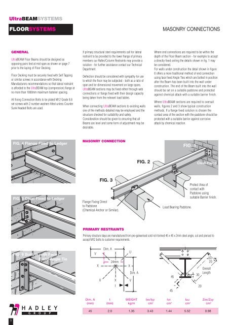
MASONRY CONNECTIONTAIL<br />
FIG. 3<br />
Flange Fixing Direct<br />
to Padstone<br />
(Chemical Anchor or Similar).<br />
PRIMARY RESTRAINTS<br />
V<br />
24mm<br />
X X<br />
U<br />
Dim. A<br />
X<br />
t<br />
U<br />
Dim. A<br />
V<br />
FIG. 2<br />
MASONRY CONNECTIONS<br />
Where end connections are required to be within the<br />
depth of the Floor Beam section - for example to accept<br />
a directly fixed ceiling the details shown in fig. 1 may<br />
be considered.<br />
For walls under construction the detail shown in figure<br />
6 offers a more traditional method of end connection<br />
using face fixed Angle Ties which are bolted in position<br />
after the Beam has been built into the wall under<br />
construction. The end of the Beam built into the wall<br />
should be set on a suitable padstone and protected<br />
against chemical attack with a suitable barrier finish.<br />
Where <strong>UltraBEAM</strong> sections are required to oversail<br />
walls, figures 2 and 3 show typical construction<br />
methods. If a flange fixed solution is chosen the<br />
contact area of the section with the padstone should be<br />
protected with a suitable barrier against corrosive<br />
attack by chemical reaction.<br />
FIG. 1<br />
Load Bearing Padstone.<br />
Dim. A t WEIGHT lxx/lyy lvv luu Zxx/Zyy<br />
(mm) (mm) kg/m cm 4 cm 4 cm 4 cm 3<br />
45 2.0 1.35 3.43 1.44 5.52 0.98<br />
45<br />
45<br />
Cleat Fixing<br />
Protect Area of<br />
contact with<br />
Padstone using<br />
suitable Barrier finish.<br />
Primary structure stays are manufactured from pre-galvanised cold roll-formed 45 x 45 x 2mm steel angle, cut and pierced to<br />
accept M12 bolts to customer requirements.<br />
30<br />
20<br />
20<br />
Overall<br />
<strong>Le</strong>ngth