2013 Product Range - MKT Metall-Kunststoff-Technik GmbH & Co. KG
2013 Product Range - MKT Metall-Kunststoff-Technik GmbH & Co. KG
2013 Product Range - MKT Metall-Kunststoff-Technik GmbH & Co. KG

Create successful ePaper yourself
Turn your PDF publications into a flip-book with our unique Google optimized e-Paper software.
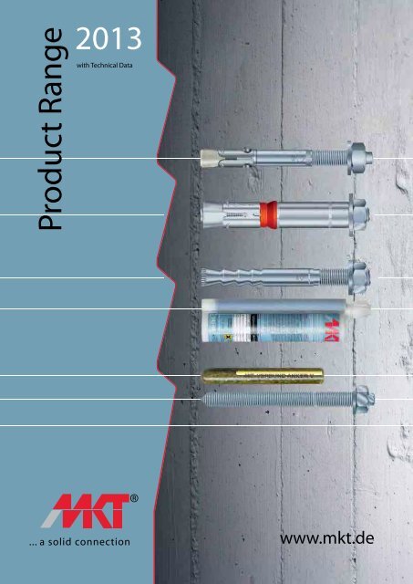
<strong>Product</strong> <strong>Range</strong><br />
<strong>2013</strong><br />
with Technical Data<br />
www.mkt.de
All technical details may be subject<br />
to change without notice.<br />
We do not accept liability for<br />
printing mistakes or omissions.<br />
For the latest technical data log on<br />
to our website www.mkt.de<br />
... a solid connection<br />
<strong>MKT</strong> was founded in 1990 as a manufacturer of high quality,<br />
internationally approved fastening systems and certified in 1996<br />
according to DIN EN ISO 9001. Meanwhile, <strong>MKT</strong> - products are used<br />
worldwide. The consistent orientation of the services offered to the<br />
needs of the market resulted in significantly above the industry average<br />
growth.<br />
Please note that <strong>MKT</strong> also provides anchor sizes and designs beyond<br />
the standard product range, such as special solutions for tunnel<br />
constructions as well as stainless steel anchors from the materials 1.4529,<br />
1.4571 and 1.4462.<br />
<strong>MKT</strong> provides customer service on all technical questions anytime.<br />
New:<br />
Wedge Anchor BZ:<br />
For Wedge Anchor BZ plus now the size M27 in steel, zinc plated is<br />
available. The three available lengths all have a usable thread length<br />
up to the concrete surface. See page 8-9.<br />
Nail Anchor N:<br />
The Nail Anchor family has grown around the N-M version with internal<br />
thread. Through the dual thread M8/M10 it is possible to use one anchor<br />
with M8 and M10 threaded rods. Moreover, the versions N and NK are<br />
now available in A4 stainless steel and stainless steel HCR. See page<br />
28-29.<br />
Drop-In Anchor E/ES:<br />
SDS shank setting tools are now available to set Drop-in anchor E and<br />
ES with a hammer drill. See page 30-31.<br />
Injection Adhesive VMZ express:<br />
To work effectively even in the cold season we have expanded our<br />
proven Injection Adhesive VMZ with the express version. With the<br />
express version, significant time savings are possible even in spring<br />
and fall. See page 46-59.<br />
Injection Adhesive VMU express:<br />
To meet the increasing demand for rapidly curing injection systems we<br />
have expanded our range VMU express to include the 420ml cartridge.<br />
See page 66-73.<br />
Injection Adhesive VM-Polar:<br />
Expansion of the range of cartridge sizes with VM Polar 280 which is also<br />
suitable for silicone guns, and the size of VM Polar 420. See page 88-93.
<strong>2013</strong> PR <strong>MKT</strong><br />
Table of <strong>Co</strong>ntents<br />
Mechanical Heavy Duty Anchors<br />
Wedge Anchor BZ plus 8 - 9<br />
Wedge Anchor BZ plus A4 10-11<br />
Wedge Anchor BZ plus HCR 12-13<br />
Wedge Anchor BZ-IG / BZ-IG A4 / BZ-IG HCR 14-17<br />
Wedge Anchor B / B A4 / B HCR / B hot dip galvanized 18-23<br />
Wedge Anchor B-U / B-W 24-25<br />
Wedge Anchor B-IG / B-IG A4 26-27<br />
Nail Anchor N / N-K / N-M 28-29<br />
Drop-in Anchor E / ES / ED / E A4 / E HCR 30-35<br />
Hollow <strong>Co</strong>re Anchor Easy 36-37<br />
Highload Anchor SZ / SZ A4 38-41<br />
Highload Anchor SL / SL A4 42-43<br />
Chemical Anchors<br />
Injection System VMZ / VMZ A4 / VMZ HCR 46-53<br />
Injection System VMZ-IG / VMZ-IG A4 54-55<br />
Injection System VMZ dynamic 56-59<br />
Chemical Anchor V / V A4 / V HCR 60-63<br />
Chemical Anchor V-IG / V-IG A4 64-65<br />
Injection System VMU / VMU A4 / VMU HCR 66-73<br />
Injection System VME 74-81<br />
Injection System VM-K / VM-PY / VM-Polar 82-93<br />
Light Duty Anchors<br />
Nail Plug ND 96<br />
Universal Plug UD 97<br />
Safety Nail DZ 98<br />
Drywall Plug GKD 99<br />
Service<br />
Design Software 102-103<br />
Fire Resistance Reports 104-105<br />
NEW<br />
NEW<br />
NEW<br />
NEW<br />
NEW<br />
NEW
Approvals and Certificates<br />
... a solid connection<br />
<br />
<br />
<br />
<br />
<br />
<br />
DIN EN ISO 9001 certification<br />
European Technical Approval (ETA) with CE marking<br />
Approval by ‚Deutsches Institut für Bautechnik‘ in Berlin, Germany<br />
ICC approval, United States of America<br />
Shock approval by ‚Bundesamt für Bevölkerungsschutz‘ in Bern, Switzerland<br />
Factory Mutual (FM), U.S. approval for installation of sprinkler systems<br />
Suitable for installation of sprinkler systems as per requirements of VdS Schadenverhütung <strong>GmbH</strong>,<br />
Germany<br />
VdS Schadenverhütung <strong>GmbH</strong>, Germany, approval for installation of sprinkler systems<br />
Test report stating residual load bearing capacities after exposure of anchor to open flames<br />
30 to 120 minutes according to DIN 4102-2 (F30/R30, F60/R60, F90/R90, F120/R120)<br />
Identifies anchors that are approved for fatigue loading<br />
Material sign for stainless steel (A4 grade 316 or HCR material 1.4529)<br />
Included in <strong>MKT</strong> Design-Software<br />
4<br />
<strong>2013</strong> PR <strong>MKT</strong>
Anchor Selection<br />
Mechanical Heavy Duty Anchors<br />
Cracked <strong>Co</strong>ncrete<br />
Non-cracked <strong>Co</strong>ncrete<br />
Multiple Use in <strong>Co</strong>ncrete<br />
Pre-stressed <strong>Co</strong>ncrete<br />
Hollow Slabs<br />
Hollow Brick<br />
Solid Brick<br />
Wedge Anchor BZ plus <br />
Wedge Anchor BZ plus A4 <br />
Wedge Anchor BZ plus HCR <br />
Wedge Anchor BZ-IG <br />
Wedge Anchor BZ-IG A4 / HCR <br />
Wedge Anchor B <br />
Wedge Anchor B hot dip gal. <br />
Wedge Anchor B A4 <br />
Wedge Anchor B HCR <br />
Wedge Anchor B-IG / B-IG A4 <br />
Nail Anchor N, N-K, N-M <br />
Drop-in Anchor E, ES <br />
Drop-in Anchor E A4 / E HCR <br />
Hollow <strong>Co</strong>re Anchor Easy <br />
Highload Anchor SZ <br />
Highload Anchor SZ A4 <br />
Highload Anchor SL <br />
Highload Anchor SL A4 <br />
Chemical Anchors<br />
Injection System VMZ <br />
Injection System VMZ-IG <br />
Injection System VMZ dyn <br />
Chemical Anchor V <br />
Chemical Anchor V-IG <br />
Injection System VMU <br />
Injection System VME <br />
Injection Adhesive VM-PY <br />
Injection Adhesive VM-K, Polar <br />
Light Duty Anchors<br />
Nail Plug ND <br />
Universal Plug UD <br />
Safety Nail DZ <br />
Drywall Plug GKD <br />
<strong>2013</strong> PR <strong>MKT</strong><br />
Drywall<br />
ETA Approval<br />
DIBt Approval<br />
Fire Resistant<br />
ICC approval<br />
Approved for fatigue loading<br />
VdS<br />
5 ... a solid connection<br />
FM<br />
Swiss Shock Approval<br />
Steel, Zinc Plated<br />
Steel, Hot Dip Galvanized<br />
Stainless Steel A4/316<br />
Stainless Steel HCR<br />
Design Software available
Mechanical<br />
Heavy Duty<br />
Anchors
<strong>Product</strong> <strong>Range</strong> <strong>2013</strong><br />
Mechanical Heavy Duty Anchors<br />
Chemical Anchors<br />
Light Duty Anchors
new<br />
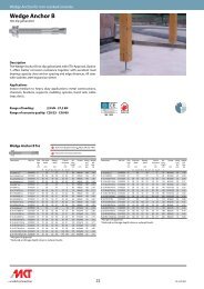
Wedge Anchor for cracked and non-cracked concrete<br />
Wedge Anchor BZ plus<br />
Steel, zinc plated<br />
Wedge Anchor BZ plus Steel, zinc plated<br />
Description Ref. No. Drill<br />
H ole<br />
Øxdepth<br />
mm<br />
... a solid connection<br />
Settingdepth<br />
mm<br />
Approved for cracked and non-cracked concrete<br />
Fixturethickness<br />
t fi x<br />
mm<br />
Anchorlength<br />
l<br />
mm<br />
Thread<br />
mm<br />
Wedge Anchor BZ plus<br />
Description<br />
The Wedge Anchor BZ plus (ETA, Option 1) combines high ultimate<br />
loads with close anchor spacing and edge distances. The special coating<br />
covering the expansion cone is heat resistant and durable enough<br />
to prevent cold welding of the expansion mechanism. This <strong>MKT</strong> patented<br />
invention also provides the proper friction between the stainless<br />
steel clip and the expansion cone throughout the entire service life of<br />
the anchor, which is a requirement for reliable crack-tested anchors.<br />
New:<br />
The M27 diameter has been added in three different lengths. All three<br />
sizes have a usable thread length up to the concrete surface.<br />
Applications<br />
Medium to heavy duty anchoring in cracked and non-cracked concrete:<br />
Steel beams, base plates, channels, tracks, wood structures.<br />
<strong>Range</strong> of Loading: 2,4 kN - 73,5 kN<br />
<strong>Range</strong> of concrete quality: C20/25 - C50/60<br />
Pkg.<br />
content<br />
pcs.<br />
Weight<br />
per<br />
pkg.<br />
kg<br />
B M<br />
B M<br />
B M<br />
B M<br />
B M<br />
B M<br />
B M<br />
B M<br />
B M<br />
B M<br />
B M<br />
B M<br />
B M<br />
B M M<br />
B M M<br />
B M M<br />
B M M<br />
B M M<br />
B M M<br />
B M M<br />
B M M<br />
B M M<br />
B M M<br />
B M M<br />
B M<br />
B M<br />
B M<br />
B M<br />
B M<br />
B M<br />
B M<br />
B M<br />
B M<br />
B M<br />
B M<br />
B M<br />
B M<br />
B M<br />
B M<br />
B M<br />
B M<br />
B M<br />
Z 8-10/75 06115101 8x60 52 10 75 8x20 100 2,99<br />
Z 8-15/80 06120101 8x60 52 15 80 8x25 100 3,14<br />
Z 8-30/95 06135101 8x60 52 30 95 8x40 100 3,60<br />
Z 8-50/115 06145101 8x60 52 50 115 8x60 100 4,24<br />
Z 8-100/165 06160101 8x60 52 100 165 8x80 50 2,94<br />
Z 10-10/90 06210101 10x75 68 10 90 10x20 50 2,94<br />
Z 10-15/95 06215101 10x75 68 15 95 10x25 50 3,06<br />
Z 10-20/100 06220101 10x75 68 20 100 10x30 50 3,18<br />
Z 10-30/110 06225101 10x75 68 30 110 10x40 50 3,44<br />
Z 10-50/130 06235101 10x75 68 50 130 10x60 50 4,95<br />
Z 10-75/155 06240101 10x75 68 75 155 10x80 50 4,55<br />
Z 10-100/180 06250101 10x75 68 100 180 10x80 50 5,16<br />
Z 10-150/230 06260101 10x75 68 150 230 10x80 25 3,49<br />
Z 70 12-15/110 06317101 12x90 80 15 110 12x30 25 2,55<br />
Z 70 12-20/115 06322101 12x90 80 20 115 12x35 25 2,66<br />
Z 70 12-30/125 06327101 12x90 80 30 125 12x45 25 2,84<br />
Z 70 12-50/145 06332101 12x90 80 50 145 12x65 25 3,23<br />
Z 70 12-65/160 06337101 12x90 80 65 160 12x80 25 3,49<br />
Z 70 12-85/180 06342101 12x90 80 85 180 12x100 25 3,84<br />
Z 70 12-105/200 06347101 12x90 80 105 200 12x115 25 4,21<br />
Z 70 12-125/220 06352101 12x90 80 125 220 12x80 25 4,93<br />
Z 70 12-145/240 06357101 12x90 80 145 240 12x80 20 4,32<br />
Z 70 12-160/255 06367101 12x90 80 160 255 12x80 20 4,59<br />
Z 70 12-190/285 06372101 12x90 80 190 285 12x80 20 4,99<br />
Z 16-15/135 06510101 16x110 97 15 135 16x35 20 4,32<br />
Z 16-25/145 06515101 16x110 97 25 145 16x45 20 4,60<br />
Z 16-50/170 06520101 16x110 97 50 170 16x70 20 5,26<br />
Z 16-80/200 06525101 16x110 97 80 200 16x80 10 3,20<br />
Z 16-100/220 06530101 16x110 97 100 220 16x80 10 3,50<br />
Z 16-140/260 06535101 16x110 97 140 260 16x80 10 4,12<br />
Z 16-180/300 06540101 16x110 97 180 300 16x80 10 4,74<br />
Z 20-30/165 06615101 20x125 114 30 165 20x50 10 4,41<br />
Z 20-60/195 06625101 20x125 114 60 195 20x70 10 5,05<br />
Z 20-100/235 06630101 20x125 114 100 235 20x80 5 3,04<br />
Z 20-130/265 06635101 20x125 114 130 265 20x80 5 3,43<br />
Z 20-150/285 06640101 20x125 114 150 285 20x80 5 3,66<br />
Z 24-30/190 06715101 24x145 133 30 190 24x55 10 6,85<br />
Z 24-60/220 06725101 24x145 133 60 220 24x85 5 3,93<br />
Z 24-75/235 06735101 24x145 133 75 235 24x100 5 4,15<br />
Z 27-30/210 06815101 28x160 146 30 210 27x62 5 5,10<br />
Z 27-60/240 06825101 28x160 146 60 240 27x92 5 5,60<br />
Z 27-100/280 06845101 28x160 146 100 280 27x132 5 6,40<br />
Other lengths on demand.<br />
Wedge Anchor BZ plus M24/M27<br />
8<br />
Wedge Anchor BZ-U plus With large washer DIN EN ISO 7093-1<br />
(formerly: DIN 9021)<br />
Description Ref. No. Drill<br />
H ole<br />
Øxdepth<br />
mm<br />
Settingdepth<br />
mm<br />
approv ed<br />
M10 - M16<br />
Fixturethickness<br />
t fi x<br />
mm<br />
Anchorlength<br />
l<br />
mm<br />
Ø<br />
Washer<br />
mm<br />
R30-R120<br />
Approved for cracked and non-cracked concrete<br />
Thread<br />
mm<br />
Pkg.<br />
content<br />
pcs.<br />
Weight<br />
per<br />
pkg.<br />
kg<br />
B M<br />
B M<br />
B M<br />
B M<br />
B M<br />
B M<br />
B M<br />
B M<br />
B M<br />
B M<br />
B M<br />
B M M<br />
B M M<br />
B M M<br />
B M M<br />
B M M<br />
B M M<br />
B M<br />
B M<br />
B M<br />
B M<br />
B M<br />
B M<br />
B M<br />
B M<br />
B M<br />
B M<br />
B M<br />
Z-U 8-10/75 06115701 8x60 52 10 75 24 8x20 100 3,46<br />
Z-U 8-15/80 06120701 8x60 52 15 80 24 8x25 100 3,52<br />
Z-U 8-30/95 06135701 8x60 52 30 95 24 8x40 100 4,01<br />
Z-U 8-50/115 06145701 8x60 52 50 115 24 8x60 100 4,63<br />
Z-U 10-10/90 06210701 10x75 68 10 90 30 10x20 50 3,30<br />
Z-U 10-15/95 06215701 10x75 68 15 95 30 10x25 50 3,45<br />
Z-U 10-20/100 06220701 10x75 68 20 100 30 10x30 50 3,55<br />
Z-U 10-30/110 06225701 10x75 68 30 110 30 10x40 50 3,95<br />
Z-U 10-50/130 06235701 10x75 68 50 130 30 10x60 50 4,31<br />
Z-U 10-100/180 06250701 10x75 68 100 180 30 10x80 50 6,02<br />
Z-U 10-150/230 06260701 10x75 68 150 230 30 10x80 25 3,73<br />
Z-U 70 12-15/110 06317701 12x90 80 15 110 37 12x30 25 2,86<br />
Z-U 70 12-30/125 06327701 12x90 80 30 125 37 12x45 25 3,26<br />
Z-U 70 12-50/145 06332701 12x90 80 50 145 37 12x65 25 3,68<br />
Z-U 70 12-125/220 06352701 12x90 80 125 220 37 12x80 25 5,47<br />
Z-U 70 12-160/255 06367701 12x90 80 160 255 37 12x80 20 4,91<br />
Z-U 70 12-190/285 06372701 12x90 80 190 285 37 12x80 20 5,50<br />
Z-U 16-25/145 06515701 16x110 97 25 145 50 16x45 20 5,15<br />
Z-U 16-100/220 06530701 16x110 97 100 220 50 16x80 10 3,76<br />
Z-U 16-140/260 06535701 16x110 97 140 260 50 16x80 10 4,50<br />
Z-U 16-180/300 06540701 16x110 97 180 300 50 16x80 10 4,99<br />
Z-U 20-30/165 06615701 20x125 114 30 165 60 20x50 10 4,98<br />
Z-U 20-60/195 06625701 20x125 114 60 195 60 20x70 10 5,62<br />
Z-U 20-100/235 06630701 20x125 114 100 235 60 20x80 5 3,31<br />
Z-U 20-130/265 06635701 20x125 114 130 265 60 20x80 5 3,68<br />
Z-U 20-150/285 06640701 20x125 114 150 285 60 20x80 5 3,92<br />
Z-U 24-30/190 06715701 24x145 133 30 190 72 24x55 10 7,95<br />
Z-U 24-60/220 06725701 24x145 133 60 220 72 24x85 5 5,05<br />
Other lengths on demand.<br />
<br />
<br />
<br />
<br />
<br />
<br />
<strong>2013</strong> PR <strong>MKT</strong>
Extract from Permissible Service <strong>Co</strong>nditions of ETA-99/0010<br />
Approved loads for single anchor without influence of spacing and edge distance.<br />
Total safety factor as per ETAG 001 included (γ M und γ F ).<br />
Mechanical Heavy Duty Anchors<br />
Loads and performance data Wedge Anchor BZ plus M8 M10 70 M12 M16 M20 M24 M27<br />
cracked concrete<br />
Mean ultimate loads, tension C25/30 Num [kN] 10,5 14,9 28,1 35,5 54,3 79,8 80,0<br />
Mean ultimate loads, shear C25/30 Vum [kN] 11,5 18,3 33,7 49,5 68,6 131,8 181,7<br />
Approved loads, tension C20/25 appr. N [kN] 2,4 4,3 7,6 11,9 17,1 21,1 24,0<br />
C25/30 appr. N [kN] 2,6 4,7 8,3 13,1 18,8 23,3 26,2<br />
C30/37 appr. N [kN] 2,9 5,2 9,3 14,5 20,9 25,8 29,1<br />
C40/50 appr. N [kN] 3,4 6,0 10,8 16,8 24,2 29,8 33,9<br />
C50/60 appr. N [kN] 3,7 6,6 11,8 18,5 26,6 32,8 37,1<br />
non-cracked concrete<br />
Approved loads, tension C20/25 appr. N [kN] 5,7 7,6 11,9 16,7 24,0 29,6 33,5<br />
C25/30 appr. N [kN] 6,3 8,4 13,0 18,3 26,3 32,6 36,7<br />
C30/37 appr. N [kN] 7,0 9,3 14,5 20,3 29,2 36,1 40,8<br />
C40/50 appr. N [kN] 7,5 10,7 16,8 23,5 33,8 41,7 47,4<br />
C50/60 appr. N [kN] 7,5 11,8 18,4 25,8 37,2 45,9 52,0<br />
cracked / non-cracked concrete<br />
Approved loads, shear C20/25 appr. V [kN] 8,6 12,6 17,1 26,9/34,3 34,3/37,1 42,3/59,2 47,9/67,1<br />
m C25/30 appr. V [kN] 8,6 12,6 17,1 29,6/34,3 37,1 46,5/65,1 52,5/73,5<br />
Approved bending moments appr. M [Nm] 13,1 26,9 46,9 119,4 195,0 513,1 760,9<br />
Spacing and edge distance<br />
Effective anchorage depth hef [mm] 46 60 70 85 100 115 125<br />
Characteristic spacing scr, N [mm] 138 180 210 255 300 345 375<br />
Characteristic edge distance ccr, N [mm] 69 90 105 127,5 150 172,5 187,5<br />
Minimum spacing and edge distance for standard thickness of concrete member<br />
Standard thickness of concrete slab hstd [mm] 100 120 140<br />
cracked concrete<br />
170 200 230 250<br />
Minimum spacing / for edge distance c smin / c [mm] 40 / 70 45 / 70 60 / 100 60 / 100 95 / 150 100 / 180 125/300<br />
Minimum edge distance / for spacing s cmin / s [mm] 40 / 80 45 / 90 60 / 140 60 / 180 95 / 200 100 / 220 180/540<br />
non-cracked concrete<br />
Minimum spacing / for edge distance c smin / c [mm] 40 / 80 45 / 70 60 / 120 65 / 120 90 / 180 100 / 180 125/300<br />
Minimum edge distance / for spacing s cmin / s [mm] 50 / 100 50 / 100 75 / 150 80 / 150 130 / 240 100 / 220 180/540<br />
Minimum spacing and edge distance for minimum thickness of concrete member<br />
Minimum thickness of concrete slab hmin [mm] 80 100 120<br />
cracked concrete<br />
140 - - -<br />
Minimum spacing / for edge distanc e c smin / c [mm] 40 / 70 45 / 90 60 / 100 70 / 160 - - -<br />
Minimum edge distance / for spacing s cmin / s [mm] 40 / 80 50 / 115 60 / 140 80 / 180 - - -<br />
non-cracked concrete<br />
Minimum spacing / for edge distance c smin / c [mm] 40 / 80 60 / 140 60 / 120 80 / 180 - - -<br />
Minimum edge distance / for spacing s<br />
Installation parameters<br />
cmin / s [mm] 50 / 100 90 / 140 75 / 150 90 / 200 - - -<br />
Drill hole diameter do [mm] 8 10 12 16 20 24 28<br />
Diameter of clearance hole in the fixture df [mm] 9 12 14 18 22 26 31<br />
Depth of drill hole h1 [mm] 60 75 90 110 125 145 160<br />
Installation torque Tinst [Nm] 20 25 45 90 160 200 300<br />
Width across nut SW [mm] 13 17 19 24 30 36 41<br />
For anchor designing, an easy to operate CD-ROM is available on request or can be downloaded at www.mkt.de<br />
h m hmin<br />
d0<br />
Installation<br />
<strong>2013</strong> PR <strong>MKT</strong><br />
90°<br />
hef<br />
L<br />
tfix<br />
BZ M8 A4<br />
Tinst<br />
BZ<br />
BZ M8<br />
BZ<br />
Nm<br />
new<br />
9 ... a solid connection<br />
Mechanical Heavy Duty Anchors
Wedge Anchor for cracked and non-cracked concrete<br />
Wedge Anchor BZ plus A4<br />
Stainless Steel A4/316<br />
Wedge Anchor BZ plus A4 Stainless steel A4/316<br />
Description Ref. No. Drill<br />
H ole<br />
Øxdepth<br />
mm<br />
... a solid connection<br />
Settingdepth<br />
mm<br />
Approved for cracked and non-cracked concrete<br />
Fixturethickness<br />
t fi x<br />
mm<br />
Anchorlength<br />
l<br />
mm<br />
Thread<br />
mm<br />
Wedge Anchor BZ plus A4<br />
Wedge Anchor BZ-U plus A4<br />
Description<br />
The Wedge Anchor BZ plus A4 (ETA, Option 1) combines high ultimate<br />
loads with close anchor spacing and edge distances. The special<br />
coating covering the expansion cone is heat resistant and durable<br />
enough to prevent cold welding of the expansion mechanism. This<br />
<strong>MKT</strong> patented invention also provides the proper friction between<br />
the stainless steel clip and the expansion cone throughout the entire<br />
service life of the anchor, which is a requirement for reliable cracktested<br />
anchors.<br />
Applications<br />
Medium to heavy duty anchoring in cracked and non-cracked concrete:<br />
Steel beams, channels, facade substructures, chairs in sports<br />
arenas, wood structures.<br />
<strong>Range</strong> of Loading: 2,4 kN - 52,6 kN<br />
<strong>Range</strong> of concrete quality: C20/25 - C50/60<br />
Pkg.<br />
content<br />
pcs.<br />
Weight<br />
per pkg.<br />
kg<br />
B M<br />
B M<br />
B M<br />
B M<br />
B M<br />
B M<br />
B M<br />
B M<br />
B M<br />
B M<br />
B M M<br />
B M M<br />
B M M<br />
B M M<br />
B M M<br />
B M M<br />
B M M<br />
B M M<br />
B M<br />
B M<br />
B M<br />
B M<br />
B M<br />
B M<br />
B M<br />
B M<br />
Z 8-10/75 A4 02115501 8x60 54 10 75 8x20 100 3,02<br />
Z 8-15/80 A4 02120501 8x60 54 15 80 8x25 100 3,16<br />
Z 8-30/95 A4 02135501 8x60 54 30 95 8x40 100 3,68<br />
Z 8-50/115 A4 02145501 8x60 54 50 115 8x60 100 4,34<br />
Z 10-10/90 A4 02210501 10x75 68 10 90 10x20 50 2,97<br />
Z 10-15/95 A4 02215501 10x75 68 15 95 10x25 50 3,12<br />
Z 10-20/100 A4 02220501 10x75 68 20 100 10x30 50 3,25<br />
Z 10-30/110 A4 02225501 10x75 68 30 110 10x40 50 3,48<br />
Z 10-50/130 A4 02235501 10x75 68 50 130 10x60 50 4,02<br />
Z 10-100/180 A4 02250501 10x75 68 100 180 10x80 50 5,26<br />
Z 70 12-15/110 A4 02317501 12x90 80 15 110 12x30 25 2,55<br />
Z 70 12-20/115 A4 02322501 12x90 80 20 115 12x35 25 2,66<br />
Z 70 12-30/125 A4 02327501 12x90 80 30 125 12x45 25 2,84<br />
Z 70 12-50/145 A4 02332501 12x90 80 50 145 12x65 25 3,23<br />
Z 70 12-85/180 A4 02342501 12x90 80 85 180 12x100 25 3,84<br />
Z 70 12-125/220 A4 02352501 12x90 80 125 220 12x80 25 4,93<br />
Z 70 12-160/255 A4 02367501 12x90 80 160 255 12x80 20 4,59<br />
Z 70 12-190/285 A4 02372501 12x90 80 190 285 12x80 20 4,99<br />
Z 16-25/145 A4 02515501 16x110 97 25 145 16x45 20 4,68<br />
Z 16-50/170 A4 02520501 16x110 97 50 170 16x70 20 5,36<br />
Z 16-100/220 A4 02530501 16x110 97 100 220 16x80 10 3,59<br />
Z 20-30/165 A4 02615501 20x125 114 30 165 20x50 10 4,51<br />
Z 20-60/195 A4 02625501 20x125 114 60 195 20x70 10 5,14<br />
Z 20-100/235 A4 02630501 20x125 114 100 235 20x80 5 3,09<br />
Z 20-130/265 A4 02635501 20x125 114 130 265 20x80 5 3,48<br />
Z 20-150/285 A4 02640501 20x125 114 150 285 20x80 5 3,73<br />
Other lengths on demand. BZ plus M24 A4 on demand.<br />
10<br />
approv ed<br />
M10 - M16<br />
Wedge Anchor BZ-U plus A4<br />
Description Ref. No. Drill<br />
H ole<br />
Øxdepth<br />
mm<br />
Settingdepth<br />
mm<br />
With large washer DIN EN ISO 7093-1<br />
(formerly DIN 9021)<br />
Approved for cracked and non-cracked concrete<br />
Fixturethickness<br />
t fi x<br />
mm<br />
R30-R120<br />
Anchorlength<br />
l<br />
mm<br />
Ø<br />
Washer<br />
mm<br />
Thread<br />
mm<br />
Pkg.<br />
content<br />
pcs.<br />
Weight<br />
per<br />
pkg.<br />
kg<br />
B M<br />
B M<br />
B M<br />
B M<br />
B M<br />
B M<br />
B M<br />
B M<br />
B M M<br />
B M M<br />
B M M<br />
B M M<br />
B M M<br />
B M M<br />
B M<br />
B M<br />
B M<br />
B M<br />
B M<br />
B M<br />
B M<br />
Z-U 8-10/75 A4 02115541 8x60 54 10 75 24 8x20 100 3,46<br />
Z-U 8-15/80 A4 02120541 8x60 54 15 80 24 8x25 100 3,60<br />
Z-U 8-30/95 A4 02135541 8x60 54 30 95 24 8x40 100 4,09<br />
Z-U 8-50/115 A4 02145541 8x60 54 50 115 24 8x60 100 4,74<br />
Z-U 10-10/90 A4 02210541 10x75 68 10 90 30 10x20 50 3,37<br />
Z-U 10-15/95 A4 02215541 10x75 68 15 95 30 10x25 50 3,53<br />
Z-U 10-30/110 A4 02225541 10x75 68 30 110 30 10x40 50 3,94<br />
Z-U 10-50/130 A4 02235541 10x75 68 50 130 30 10x60 50 4,70<br />
Z-U 70 12-15/110 A4 02317541 12x90 80 15 110 37 12x30 25 2,86<br />
Z-U 70 12-30/125 A4 02327541 12x90 80 30 125 37 12x35 25 3,26<br />
Z-U 70 12-50/145 A4 02332541 12x90 80 50 145 37 12x65 25 3,68<br />
Z-U 70 12-125/220 A4 02352541 12x90 80 125 220 37 12x80 25 5,47<br />
Z-U 70 12-160/255A4 02367541 12x90 80 160 255 37 12x80 20 4,91<br />
Z-U 70 12-190/285A4 02372541 12x90 80 180 275 37 12x80 20 4,99<br />
Z-U 16-25/145 A4 02515541 16x110 97 25 145 50 16x45 20 5,59<br />
Z-U 16-100/220 A4 02530541 16x110 97 100 220 50 16x80 10 4,01<br />
Z-U 20-30/165 A4 02615541 20x125 114 30 165 60 20x50 10 4,70<br />
Z-U 20-60/195 A4 02625541 20x125 114 60 195 60 20x70 10 5,80<br />
Z-U 20-100/235 A4 02630541 20x125 114 100 235 60 20x80 5 3,09<br />
Z-U 20-130/265 A4 02635541 20x125 114 130 265 60 20x80 5 3,68<br />
Z-U 20-150/285 A4 02640541 20x125 114 150 285 60 20x80 5 3,92<br />
Other lengths on demand.<br />
<br />
<br />
<br />
<br />
<br />
<br />
<strong>2013</strong> PR <strong>MKT</strong>
Extract from Permissible Service <strong>Co</strong>nditions of ETA-99/0010<br />
Approved loads for single anchor without influence of spacing and edge distance.<br />
Total safety factor as per ETAG 001 included (γ M und γ F ).<br />
Mechanical Heavy Duty Anchors<br />
Loads and performance data Wedge Anchor BZ plus A4 M8 M10 70 M12 M16 M20 M24<br />
cracked concrete<br />
Mean ultimate loads, tension C25/30 Num [kN] 10,8 16,7 27,5 40,0 54,3 68,8<br />
Mean ultimate loads, shear C25/30 Vum [kN] 15,4 24,4 35,4 65,9 102,9 147,8<br />
Approved loads, tension C20/25 appr. N [kN] 2,4 4,3 7,6 11,9 17,1 17,1<br />
C25/30 appr. N [kN] 2,6 4,7 8,3 13,1 18,8 18,8<br />
C30/37 appr. N [kN] 2,9 5,2 9,3 14,5 20,9 20,9<br />
C40/50 appr. N [kN] 3,4 6,0 10,8 16,8 24,2 24,2<br />
C50/60 appr. N [kN] 3,7 6,6 11,8 18,5 26,6 26,6<br />
non-cracked concrete<br />
Approved loads, tension C20/25 appr. N [kN] 5,7 7,6 11,9 16,7 24,0 24,0<br />
C25/30 appr. N [kN] 6,3 8,4 13,0 18,3 26,3 26,3<br />
C30/37 appr. N [kN] 7,0 9,3 14,5 20,3 29,2 29,2<br />
C40/50 appr. N [kN] 7,6 10,7 16,8 23,5 33,8 33,8<br />
C50/60 appr. N [kN] 7,6 11,8 18,4 25,8 37,2 37,2<br />
cracked / non-cracked concrete<br />
Approved loads, shear C20/25 appr. V [kN] 7,4 11,4 17,1 26,9/31,4 34,3/43,9 34,3/48,0<br />
m C25/30 appr. V [kN] 7,4 11,4 17,1 29,6/31,4 37,6/43,9 37,6/52,6<br />
Approved bending moments appr. M [Nm] 14,9 29,7 52,6 133,1 231,6 448,8<br />
[mm<br />
[mm<br />
mm<br />
[mm<br />
Spacing and edge distance<br />
Effective anchorage depth hef [mm] 46 60 70 85 100 100<br />
Characteristic spacing scr, N [mm] 138 180 210 255 300 300<br />
Characteristic edge distance ccr, N [mm] 69 90 105 127,5 150 150<br />
Minimum spacing and edge distance for standard thickness of concrete member<br />
cracked concrete<br />
Standard thickness of concrete slab hstd [mm] 100 120 140 160 200 200<br />
Minimum spacing / for edge distance c smin / c [mm] 40 / 70 50 / 75 60 / 100 60 / 100 95 / 150 180 / 180<br />
Minimum edge distance / for spacing s cmin / s [mm] 40 / 80 55 / 90 60 / 140 60 / 180 95 / 200 180 / 180<br />
non-cracked concrete<br />
Minimum spacing / for edge distance c smin / c [mm] 40 / 80 50 / 75 60 / 120 65 / 120 90 / 180 180 / 180<br />
Minimum edge distance / for spacing s cmin / s [mm] 50 / 100 60 / 120 75 / 150 80 / 150 130 / 240 180 / 180<br />
Minimum spacing and edge distance for minimum thickness of concrete member<br />
cracked concrete<br />
Minimum thickness of concrete slab hmin [mm] 80 100 120 140 - -<br />
Minimum spacing / for edge distance c smin / c [mm] 40 / 70 45 / 90 60 / 100 70 / 160 - -<br />
Minimum edge distance / for spacing s cmin / s [mm] 40 / 80 50 / 115 60 / 140 80 / 180 - -<br />
non-cracked concrete<br />
Minimum spacing / for edge distance c smin / c [mm] 40 / 80 60 / 140 60 / 120 80 / 180 - -<br />
Minimum edge distance / for spacing s<br />
Installation parameters<br />
cmin / s [mm] 50 / 100 90 / 140 75 / 150 90 / 200 - -<br />
Drill hole diameter do [mm] 8 10 12 16 20 24<br />
Diameter of clearance hole in the fixture df [mm] 9 12 14 18 22 26<br />
Depth of drill hole h1 [mm] 60 75 90 110 125 130<br />
Installation torque Tinst [Nm] 20 35 50 110 200 200<br />
Width across nut SW [mm] 13 17 19 24 30 36<br />
For anchor designing, an easy to operate CD-ROM is available on request or can be downloaded at www.mkt.de.<br />
h m hmin<br />
d0<br />
Installation<br />
<strong>2013</strong> PR <strong>MKT</strong><br />
90°<br />
hef<br />
L<br />
tfix<br />
BZ M8 A4<br />
BZ<br />
Tinst<br />
BZ M8<br />
BZ<br />
Nm<br />
new<br />
11 ... a solid connection<br />
Mechanical Heavy Duty Anchors
Wedge Anchor for cracked and non-cracked concrete<br />
Wedge Anchor BZ plus HCR<br />
High corrosion resistant steel 1.4529 (HCR)<br />
Description<br />
The Wedge Anchor BZ plus HCR (ETA, Option 1) combines high approved<br />
loads with close anchor spacing and edge distances. Time saving<br />
through fastening installations - no special drilling and setting tools<br />
are required. Tightening the hexagon nut expands the sleeve which<br />
produces permanent grip in cracked and non-cracked concrete. The<br />
BZ plus HCR is BZS shock approved.<br />
Applications<br />
Medium to heavy duty anchorings which are exposed to highly corrosive<br />
atmospheres with high concentration of sulphur dioxides, chlorides,<br />
humidity: attaching brackets, ventilation systems, suspended<br />
ceilings, cable trays, in road tunnels, indoor swimming pools, etc.<br />
<strong>Range</strong> of Loading: 2,4 kN - 52,6 kN<br />
<strong>Range</strong> of concrete quality: C20/25 - C50/60<br />
Wedge Anchor BZ plus HCR High corrosion resistant steel 1.4529 (HCR)<br />
Description Ref. No. Drill H ole<br />
Øxdepth<br />
... a solid connection<br />
mm<br />
Settingdepth<br />
mm<br />
Approved for cracked and non-cracked concrete<br />
Fixturethickness<br />
t fi x<br />
mm<br />
Anchorlength<br />
l<br />
mm<br />
Thread<br />
mm<br />
Pkg.<br />
content<br />
pcs.<br />
Weight<br />
per<br />
pkg.<br />
kg<br />
B Z 8-10/75 H CR 02115651 8 x 60 54 10 75 M 8x20 100 3,08<br />
B H M<br />
B H M<br />
B H M<br />
B H M<br />
B H M<br />
B H M<br />
B H M<br />
B M H M<br />
B M H M<br />
B M H M<br />
B M H M<br />
B H M<br />
B H M<br />
B H M<br />
B H M<br />
B H M<br />
B H M<br />
B H M<br />
B H M<br />
Z 8-15/80 CR 02120651 8 x 60 54 15 80 8x25 100 3,22<br />
Z 8-30/95 CR 02135651 8 x 60 54 30 95 8x40 100 3,72<br />
Z 8-50/115 CR 02145651 8 x 60 54 50 115 8x60 100 4,35<br />
Z 10-10/90 CR 02210651 10 x 75 68 10 90 10x20 50 3,02<br />
Z 10-15/95 CR 02215651 10 x 75 68 15 95 10x25 50 3,14<br />
Z 10-30/110 CR 02225651 10 x 75 68 30 110 10x40 50 3,90<br />
Z 10-50/130 CR 02235651 10 x 75 68 50 130 10x60 50 4,31<br />
Z 70 12-15/110 CR 02317651 12 x 90 80 15 110 12x30 25 2,55<br />
Z 70 12-20/115 CR 02322651 12 x 90 80 20 115 12x35 25 2,66<br />
Z 70 12-50/145 CR 02332651 12 x 90 80 50 145 12x65 25 2,23<br />
Z 70 12-125/220 CR 02352651 12 x 90 80 125 220 12x80 25 4,93<br />
Z 16-25/145 CR 02515651 16 x 110 97 25 145 16x45 20 4,90<br />
Z 16-50/170 CR 02520651 16 x 110 97 50 170 16x70 20 5,80<br />
Z 16-100/220 CR 02530651 16 x 110 97 100 220 16x80 10 3,70<br />
Z 20-30/165 CR 02615651 20 x 125 114 30 165 20x50 10 4,95<br />
Z 20-60/195 CR 02625651 20 x 125 114 60 195 20x70 10 5,14<br />
Z 20-100/235 CR 02630651 20 x 125 114 100 235 20x80 5 3,18<br />
Z 20-130/265 CR 02635651 20 x 125 114 130 265 20x80 5 3,48<br />
Z 20-150/285 CR 02640651 20 x 125 114 150 285 20x80 5 3,73<br />
Other lengths on demand.<br />
12<br />
approv ed<br />
M10 - M16<br />
R30-R120<br />
<br />
<br />
<br />
<br />
<br />
<br />
<strong>2013</strong> PR <strong>MKT</strong>
Extract from Permissible Service <strong>Co</strong>nditions of ETA-99/0010<br />
Approved loads for single anchor without influence of spacing and edge distance.<br />
Total safety factor as per ETAG 001 included (γ M und γ F ).<br />
Mechanical Heavy Duty Anchors<br />
Loads and performance data Wedge Anchor BZ plus HCR M8 M10 70 M12 M16 M20 M24<br />
cracked concrete<br />
Mean ultimate loads, tension C25/30 Num [kN] 10,8 16,7 28,0 40,0 54,3 68,8<br />
Mean ultimate loads, shear C25/30 Vum [kN] 18,4 32,9 35,5 74,6 121,5 147,8<br />
Approved loads, tension C20/25 appr. N [kN] 2,4 4,3 7,6 11,9 17,1 17,1<br />
C25/30 appr. N [kN] 2,6 4,7 8,3 13,1 18,8 18,8<br />
C30/37 appr. N [kN] 2,9 5,2 9,3 14,5 20,9 20,9<br />
C40/50 appr. N [kN] 3,4 6,0 10,8 16,8 24,2 24,2<br />
C50/60 appr. N [kN] 3,7 6,6 11,8 18,5 26,6 26,6<br />
non-cracked concrete<br />
Approved loads, tension C20/25 appr. N [kN] 5,7 7,6 11,9 16,7 24,0 24,0<br />
C25/30 appr. N [kN] 6,3 8,4 13,0 18,3 26,3 26,3<br />
C30/37 appr. N [kN] 7,0 9,3 14,5 20,3 29,2 29,2<br />
C40/50 appr. N [kN] 7,6 10,7 16,8 23,5 33,8 33,8<br />
C50/60 appr. N [kN] 7,6 11,8 18,4 25,8 37,2 37,2<br />
cracked and non-cracked concrete<br />
Approved loads, shear C20/25 appr. V [kN] 7,4 11,4 17,1 26,9/31,4 34,3/43,9 34,3/48,0<br />
m C25/30 appr. V [kN] 7,4 11,4 17,1 29,6/31,4 37,6/43,9 37,6/52,6<br />
Approved bending moments appr. M [Nm] 14,9 29,7 52,6 133,1 231,6 448,8<br />
Spacing and edge distance<br />
Effective anchorage depth hef [mm] 46 60 70 85 100 100<br />
Characteristic spacing scr, N [mm] 138 180 210 255 300 300<br />
Characteristic edge distance ccr, N [mm] 69 90 105 127,5 150 150<br />
Minimum spacing and edge distance for standard thickness of concrete member<br />
cracked concrete<br />
Standard thickness of concrete slab hstd [mm] 100 120 140 160 200 200<br />
Minimum spacing / for edge distance c smin / c [mm] 40/70 50/75 60/100 60/100 95/150 180/180<br />
Minimum edge distance / for spacing s cmin / s [mm] 40/80 55/90 60/140 60/180 95/200 180/180<br />
non-cracked concrete<br />
Minimum spacing / for edge distance c smin / c [mm] 40/80 50/75 60/120 65/120 90/180 180/180<br />
Minimum edge distance / for spacing s cmin / s [mm] 50/100 60/120 75/150 80/150 130/240 180/180<br />
Minimum spacing and edge distance for minimum thickness of concrete member<br />
cracked concrete<br />
Minimum thickness of concrete slab hmin [mm] 80 100 120 140 - -<br />
Minimum spacing / for edge distance c smin / c [mm] 40/70 45/90 60/100 70/160 - -<br />
Minimum edge distance / for spacing s cmin / s [mm] 40/80 50/115 60/140 80/180 - -<br />
non-cracked concrete<br />
Minimum spacing / for edge distance c smin / c [mm] 40/80 60/140 60/120 80/180 - -<br />
Minimum edge distance / for spacing s<br />
Installation parameters<br />
cmin / s [mm] 50/100 90/140 75/150 90/200 - -<br />
Drill hole diameter do [mm] 8 10 12 16 20 24<br />
Diameter of clearance hole in the fixture df [mm] 9 12 14 18 22 26<br />
Depth of drill hole h1 [mm] 60 75 90 110 125 130<br />
Installation torque Tinst [Nm] 20 35 50 110 200 200<br />
Width across nut SW [mm] 13 17 19 24 30 36<br />
For anchor designing, an easy to operate CD-ROM is available on request or can be downloaded at www.mkt.de<br />
h m hmin<br />
d0<br />
Installation<br />
<strong>2013</strong> PR <strong>MKT</strong><br />
90°<br />
hef<br />
L<br />
tfix<br />
BZ M8 A4<br />
BZ<br />
Tinst<br />
BZ M8<br />
BZ<br />
Nm<br />
new<br />
13 ... a solid connection<br />
Mechanical Heavy Duty Anchors
Wedge Anchor with internal thread for cracked and non-cracked concrete<br />
Wedge Anchor BZ-IG<br />
Steel, zinc plated<br />
Description<br />
The fastening system BZ-IG is the fi rst approved (ETA-02/0002) wedge<br />
anchor for cracked concrete with internal thread. It combines the<br />
benefi ts of a mechanical anchor with an easy installation and the<br />
fl exibility of an internal thread. For the fi rst time it is possible to fasten<br />
balcony and stair railings or stadium seats using a countersunk head<br />
screw at favourable costs. Since this anchor system is also approved<br />
for use with hexagon head screws and standard threaded rods a wide<br />
range of applications is possible. <strong>Co</strong>mpared to a drop in anchor the<br />
fastening system BZ-IG can carry signifi cant higher loads, even in<br />
cracked concrete. The versatility of the <strong>MKT</strong> Fastening System BZ-IG<br />
breaks new ground in design and application.<br />
Applications:<br />
Medium to heavy duty fastenings in cracked and non-cracked<br />
concrete: Railings, suspended ceilings, ladders, doors, sprinkler<br />
systems, pipe hangers and all kinds of temporary fastenings.<br />
<strong>Range</strong> of Loading: 2,0 kN - 18,5 kN<br />
<strong>Range</strong> of concrete quality: C20/25 - C50/60<br />
Wedge Anchor BZ-IG1) Wedge Anchor BZ-IG1) Pre-Installation Through Fastening<br />
Description Ref. No. Drill H ole<br />
Øxdepth<br />
<strong>Co</strong>ated Screw DIN 933 with<br />
Washer DIN EN ISO 7089 (DIN 125) 1)<br />
Description Ref. No. Fixturethickn.<br />
t fi x<br />
mm<br />
... a solid connection<br />
Wght.<br />
per<br />
pkg.<br />
kg<br />
Pkg.<br />
content<br />
pcs.<br />
S-I G 6x25 54010101 4-12 0,80 100<br />
S-I G 8x25 54110101 2-8 0,79 50<br />
S-I G 10x40 54210101 15-19 0,90 25<br />
S-I G 12x45 54310101 16-21 1,13 20<br />
Steel, zinc plated; Pre-Installation<br />
Approved for cracked and non-cracked concrete<br />
Anchorlength<br />
Thread<br />
Ø x length<br />
Weight per<br />
pkg.<br />
pkg.<br />
content<br />
mm mm mm kg pcs.<br />
B Z-I G M 6-0 03600101 8 x 60 50 M 6x20 1,42 100<br />
B Z-I G M 8-0 03610101 10 x 75 62 M 8x22 1,31 50<br />
B Z-I G M 10-0 03620101 12 x 90 70 M 10x23 1,08 25<br />
B Z-I G M 12-0 03630101 16 x 105 86 M 12x27 2,03 20<br />
<strong>Co</strong>ated <strong>Co</strong>untersunk Screw DIN 7991<br />
with <strong>Co</strong>untersunk Washer 1)<br />
Description Ref. No. Fixturethickn.<br />
t fi x<br />
mm<br />
Wght.<br />
per<br />
pkg.<br />
kg<br />
Pkg.<br />
content<br />
pcs.<br />
SK-I G 6x25 55013101 6-14 0,53 100<br />
SK-I G 8x30 55112101 9-15 0,59 50<br />
SK-I G 10x30 55211101 8-11 0,48 25<br />
SK-I G 12x35 55311101 9-14 0,64 20<br />
<strong>Co</strong>ated Hex Nut DIN 933 with<br />
Washer DIN EN ISO 7089 (DIN 125) 1)<br />
Description Ref. No. Wght.<br />
per<br />
pkg.<br />
kg<br />
Pkg.<br />
content<br />
pcs<br />
M U-I G 6 56005101 0,32 100<br />
M U-I G 8 56105101 0,35 50<br />
M U-I G 10 56205101 0,36 25<br />
M U-I G 12 56305101 0,45 20<br />
1) Screws (Strength class 8.8) or hex nuts and washers to be ordered separately.<br />
Other screw lengths according to DIN 933 on demand.<br />
Threaded stud must have at least the strength of 8.8.<br />
Threaded studs with the certifi cate see page 71.<br />
Setting Tool BZ-IG<br />
for Pre-Installation<br />
Description Ref. No. Wght.<br />
per<br />
pkg.<br />
kg<br />
B Z-I GS M 6V 43005150 0,43<br />
B Z-I GS M 8V 43100150 0,44<br />
B Z-I GS M 10V 43200150 0,46<br />
B Z-I GS M 12V 43300150 0,56<br />
14<br />
Description Ref. No. Drill H ole<br />
Øxdepth<br />
mm<br />
Setting Tool BZ-IG<br />
for Through Fastening<br />
Description Ref. No. Weight per<br />
package<br />
kg<br />
B Z-I GS M 6D 43005155 0,32<br />
B Z-I GS M 8D 43100155 0,33<br />
B Z-I GS M 10D 43200155 0,33<br />
B Z-I GS M 12D 43300155 0,35<br />
<strong>Co</strong>ated Screw DIN 933 with<br />
Washer DIN EN ISO 7089 (DIN 125) 1)<br />
Description Ref. No. Wght.<br />
per pkg.<br />
kg<br />
Pkg.<br />
content<br />
pcs<br />
S-I G 6x16 54020101 0,64 100<br />
S-I G 8x18 54120101 0,68 50<br />
S-I G 10x20 54220101 0,64 25<br />
S-I G 12x25 54320101 0,67 20<br />
Pre-installation:<br />
For pre-installation the anchor gets installed<br />
below the concrete surface. When the coated<br />
screw gets removed the anchor leaves fl ush<br />
with the concrete surface. So it´s excellent for<br />
temporary fastenings.<br />
Through fastening:<br />
If through-fastening is used the fi xture can<br />
be used as drilling template. Afterwards<br />
the anchor can be installed through the<br />
clearance hole in the fi xture. So it combines<br />
easy installation with the aesthetics of a<br />
screw head.<br />
Fixturethickness<br />
t fi x<br />
mm<br />
Typ<br />
S-I G<br />
Steel, zinc plated; Through Fastening<br />
Approved for cracked and non-cracked concrete<br />
Typ<br />
SK-I G<br />
Anchorlength<br />
l<br />
mm<br />
Thread<br />
Ø x<br />
length<br />
mm<br />
Weight<br />
per<br />
pkg.<br />
kg<br />
<strong>Co</strong>ated <strong>Co</strong>untersunk Screw DIN 7991<br />
with <strong>Co</strong>untersunk Washer 1)<br />
Description Ref. No. Wght.<br />
per pkg.<br />
kg<br />
pkg.<br />
content<br />
B Z-I G M 6-10 03602101 8 x 60 10 14 60 M 6 x 20 1,80 100<br />
B Z-I G M 6-20 03604101 8 x 60 20 24 70 M 6 x 20 2,20 100<br />
B Z-I G M 6-30 03606101 8 x 60 30 34 80 M 6 x 20 2,60 100<br />
B Z-I G M 8-10 03611101 10 x 75 10 15 72 M 8 x 22 1,65 50<br />
B Z-I G M 8-20 03612101 10 x 75 20 25 82 M 8 x 22 1,95 50<br />
B Z-I G M 8-30 03613101 10 x 75 30 35 92 M 8 x 22 2,25 50<br />
B Z-I G M 10-10 03621101 12 x 90 10 16 80 M 10 x 23 1,32 25<br />
B Z-I G M 10-20 03622101 12 x 90 20 26 90 M 10 x 23 1,48 25<br />
B Z-I G M 10-30 03623101 12 x 90 30 36 100 M 10 x 23 1,76 25<br />
B Z-I G M 12-10 03631101 16 x 105 10 17 96 M 12 x 27 2,34 20<br />
B Z-I G M 12-20 03632101 16 x 105 20 27 106 M 12 x 27 2,66 20<br />
B Z-I G M 12-30 03633101 16 x 105 30 37 116 M 12 x 27 2,97 20<br />
1) Screws (Strength class 8.8) to be ordered separately.<br />
M 8 - M 12<br />
R30-R120<br />
<br />
<br />
<br />
<br />
<br />
<br />
pcs<br />
Pkg.<br />
content<br />
pcs<br />
SK-I G 6x16 55010101 0,64 100<br />
SK-I G 8x20 55110101 0,60 50<br />
SK-I G 10x25 55210101 0,62 25<br />
SK-I G 12x30 55310101 0,80 20<br />
<strong>2013</strong> PR <strong>MKT</strong>
Extract from Permissible Service <strong>Co</strong>nditions of ETA-02/0002<br />
Approved loads for single anchor without influence of spacing and edge distance.<br />
Total safety factor as per ETAG 001 included (γ M und γ F ).<br />
Mechanical Heavy Duty Anchors<br />
Loads and performance data Wedge Anchor BZ-IG M 6 M 8 M 10 M 12<br />
cracked concrete<br />
Mean ultimate loads, tension C25/30 Num [kN] 14,1 19,8 28,3 45,9<br />
Mean ultimate loads, shear C25/30 Vum [kN] 8,7 11,4 14,8 33,9<br />
Approved loads, tension C20/25 appr. N [kN] 2,0 3,6 4,8 7,9<br />
C25/30 appr. N [kN] 2,2 3,9 5,2 8,7<br />
C30/37 appr. N [kN] 2,4 4,4 5,8 9,7<br />
C40/50 appr. N [kN] 2,8 5,0 6,7 11,2<br />
C50/60 appr. N [kN] 3,1 5,5 7,4 12,3<br />
non-cracked concrete<br />
Approved loads, tension C20/25 appr. N [kN] 4,8 6,3 7,9 11,9<br />
C25/30 appr. N [kN] 5,2 7,0 8,7 13,1<br />
C30/37 appr. N [kN] 5,8 7,7 9,7 14,5<br />
C40/50 appr. N [kN] 6,7 9,0 11,2 16,8<br />
C50/60 appr. N [kN] 7,4 9,8 12,3 18,5<br />
cracked and non-cracked concrete<br />
Approved loads, shear (Pre-Installation) m C20/25 appr. V [kN] 3,3 3,9 5,9 14,7<br />
Approved loads, shear (Through Fastening) m C20/25 appr. V [kN] 2,9 4,3 6,2 13,9<br />
Approved bending moments (Pre-Installation) appr. M [Nm] 7,0 17,1 34,2 59,8<br />
Approved bending moments (Through Fastening) appr. M [Nm] 20,6 30,4 43,4 118,3<br />
Spacing and edge distance<br />
Effective anchorage depth hef [mm] 45 58 65 80<br />
Characteristic spacing scr, N [mm] 135 174 195 240<br />
Characteristic edge distance ccr, N [mm] 67,5 87 97,5 120<br />
cracked concrete<br />
Minimum spacing / for edge distance c smin / c [mm] 50 / 60 60 / 80 70 / 100 80 / 120<br />
Minimum edge distance / for spacing s cmin / s [mm] 50 / 75 60 / 100 70 / 100 80 / 120<br />
non-cracked concrete<br />
Minimum spacing / for edge distance c smin / c [mm] 50 / 80 60 / 100 65 / 120 80 / 160<br />
Minimum edge distance / for spacing s cmin / s [mm] 50 / 115 60 / 155 70 / 170 100 / 210<br />
Minimum thickness of concrete slab<br />
Installation parameters<br />
hmin [mm] 100 120 130 160<br />
Drill hole diameter do [mm] 8 10 12 16<br />
Diameter of clearance hole in the fixture - Pre-Installation df [mm] 7 9 12 14<br />
Diameter of clearance hole in the fixture - Through Fastening df [mm] 9 12 14 18<br />
Depth of drill hole h1 [mm] 60 75 90 105<br />
Installation torque Screw DIN 933 Tinst [Nm] 10 30 30 55<br />
<strong>Co</strong>untersunk screw Tinst [Nm] 10 25 40 50<br />
Threaded rod Tinst [Nm] 8 25 30 45<br />
Width across nut Screw DIN 933 SW [mm] 10 13 17 19<br />
Internal hexagon size <strong>Co</strong>untersunk screw SW [mm] - - 6 8<br />
Torx® size <strong>Co</strong>untersunk screw T30 T45 - -<br />
Min. thickness of fixture Screw DIN 933 or Threaded rod tfix m [mm] 1 / 51) 1 / 71) 1 / 81) 1 / 91) Min. thickness of fixture <strong>Co</strong>untersunk screw tfix m [mm] 5 / 91) 7 / 121) 8 / 141) 9 / 161) 1) Pre-Installation / Through Installation. For anchor designing, an easy to operate CD-ROM is available on request or can be downloaded at www.mkt.de.<br />
Pre-installation:<br />
h m hmin<br />
Through fastening:<br />
h m hmin<br />
d0<br />
hef<br />
Installation (Pre-installation)<br />
L<br />
Installation (Through fastening)<br />
<strong>2013</strong> PR <strong>MKT</strong><br />
90°<br />
90°<br />
tfix<br />
tfix tfix hef tfix<br />
tfix tfix<br />
BZ<br />
BZ<br />
BZ<br />
Tinst<br />
BZ<br />
d0<br />
BZ M8<br />
BZ M8<br />
BZ<br />
BZ<br />
BZ<br />
L<br />
Nm<br />
Nm<br />
Dimension countersunk<br />
washer[mm]<br />
d1 d2 h<br />
SK M 6 16,5 9,5 3,9<br />
SK M 8 20,5 11,5 5,0<br />
SK M 10 24,5 14,5 5,7<br />
SK M 12 29,5 17,5 6,7<br />
<strong>Co</strong>untersunk head<br />
15 ... a solid connection<br />
h<br />
d1<br />
d2<br />
Tinst<br />
45°<br />
Mechanical Heavy Duty Anchors
Wedge Anchor with internal thread for cracked and non-cracked concrete<br />
Wedge Anchor BZ-IG A4<br />
Stainless Steel A4/316<br />
Description<br />
The fastening system BZ-IG A4 is the fi rst approved (ETA-02/0002)<br />
wedge anchor for cracked concrete with internal thread. It combines<br />
the benefi ts of a mechanical anchor with an easy installation and the<br />
fl exibility of an internal thread. For the fi rst time it is possible to fasten<br />
balcony and stair railings or stadium seats using a countersunk head<br />
screw at favourable costs. Since this anchor system is also approved<br />
for use with hexagon head screws and standard threaded rods a wide<br />
range of applications is possible. <strong>Co</strong>mpared to a drop in anchor the<br />
fastening system BZ-IG A4 can carry signifi cant higher loads, even in<br />
cracked concrete. The versatility of the <strong>MKT</strong> Fastening System BZ-IG<br />
breaks new ground in design and application.<br />
Applications<br />
Medium to heavy duty fastenings in cracked and non-cracked concrete:<br />
Railings, chairs in sports arenas, facade substructures, suspended<br />
ceilings, ladders, doors, sprinkler systems, pipe hangers and all kinds<br />
of temporary fastenings.<br />
<strong>Range</strong> of Loading: 2,0 kN - 18,5 kN<br />
<strong>Range</strong> of concrete quality: C20/25 - C50/60<br />
Wedge Anchor BZ-IG A41) Wedge Anchor BZ-IG A41) Pre-Installation Through Fastening<br />
Description Ref. No. Drill H ole<br />
Øxdepth<br />
<strong>Co</strong>ated Screw DIN 933 with<br />
Washer DIN EN ISO 7089 (DIN 125) 1)<br />
Description Ref. No. Fixturethickn.<br />
t fi x<br />
mm<br />
... a solid connection<br />
Wght.<br />
per<br />
pkg.<br />
kg<br />
Pkg.<br />
content<br />
pcs.<br />
S-I G 6x25 A4 54010501 4-12 0,80 100<br />
S-I G 8x25 A4 54110501 2-8 0,79 50<br />
S-I G 10x40 A4 54210501 15-19 0,90 25<br />
S-I G 12x45 A4 54310501 16-21 1,13 20<br />
Stainless steel A4/316; Pre-Installation<br />
Approved for cracked and non-cracked concrete<br />
Anchorlength<br />
Thread<br />
Ø x length<br />
Weight per<br />
pkg.<br />
pkg.<br />
content<br />
mm mm mm kg pcs.<br />
B Z-I G M 6-0 A4 03600501 8 x 60 50 M 6x20 1,42 100<br />
B Z-I G M 8-0 A4 03610501 10 x 75 62 M 8x22 1,31 50<br />
B Z-I G M 10-0 A4 03620501 12 x 90 70 M 10x23 1,08 25<br />
B Z-I G M 12-0 A4 03630501 16 x 105 86 M 12x27 2,03 20<br />
<strong>Co</strong>ated <strong>Co</strong>untersunk Screw DIN 7991<br />
with <strong>Co</strong>untersunk Washer 1)<br />
Description Ref. No. Fixturethickn.<br />
t fi x<br />
mm<br />
Wght.<br />
per<br />
pkg.<br />
kg<br />
Pkg.<br />
content<br />
pcs.<br />
SK-I G 6x25 A4 55013501 6-14 0,53 100<br />
SK-I G 8x30 A4 55112501 9-15 0,59 50<br />
SK-I G 10x30 A4 55211501 8-11 0,48 25<br />
SK-I G 12x35 A4 55311501 9-14 0,64 20<br />
<strong>Co</strong>ated Hex Nut DIN 933 with<br />
Washer DIN EN ISO 7089 (DIN 125) 1)<br />
Description Ref. No. Wght.<br />
per<br />
pkg.<br />
kg<br />
1) Screws or hex nuts and washers to be ordered separately.<br />
Anchor system in high corossion restistant steel grade 1.4529 on demand.<br />
Other screw lengths according to DIN 933 on demand.<br />
Setting Tool BZ-IG<br />
for Pre-Installation<br />
Description Ref. No. Wght.<br />
per<br />
pkg.<br />
kg<br />
B Z-I GS M 6V 43005150 0,43<br />
B Z-I GS M 8V 43100150 0,44<br />
B Z-I GS M 10V 43200150 0,46<br />
B Z-I GS M 12V 43300150 0,56<br />
Pkg.<br />
content<br />
pcs<br />
M U-I G 6 A4 56005501 0,32 100<br />
M U-I G 8 A4 56105501 0,35 50<br />
M U-I G 10 A4 56205501 0,36 25<br />
M U-I G 12 A4 56305501 0,45 20<br />
16<br />
Description Ref. No. Drill H ole<br />
Øxdepth<br />
mm<br />
<strong>Co</strong>ated Screw DIN 933 with<br />
Washer DIN EN ISO 7089 (DIN 125) 1)<br />
Description Ref. No. Wght.<br />
per pkg.<br />
kg<br />
Pkg.<br />
content<br />
pcs<br />
S-I G 6x16 A4 54020501 0,64 100<br />
S-I G 8x18 A4 54120501 0,68 50<br />
S-I G 10x20 A4 54220501 0,64 25<br />
S-I G 12x25 A4 54320501 0,67 20<br />
Pre-installation:<br />
For pre-installation the Anchor gets installed<br />
below the concrete surface. When the coated<br />
screw gets removed the anchor leaves fl ush<br />
with the concrete surface. So it´s excellent for<br />
temporary fastenings.<br />
Through fastening:<br />
If through-fastening is used the fi xture can<br />
be used as drilling template. Afterwards<br />
the Anchor can be installed through the<br />
clearance hole in the fi xture. So it combines<br />
easy installation with the aesthetics of a<br />
screw head.<br />
M 8 - M 12<br />
Fixturethickness<br />
t fi x<br />
mm<br />
Typ<br />
S-I G<br />
Typ<br />
SK-I G<br />
R30-R120<br />
Anchorlength<br />
l<br />
mm<br />
Thread<br />
Ø x<br />
length<br />
mm<br />
Weight<br />
per<br />
pkg.<br />
kg<br />
<br />
Stainless steel A4/316; Through Fastening<br />
<br />
<br />
<br />
<br />
<br />
Approved for cracked and non-cracked concrete<br />
<strong>Co</strong>ated <strong>Co</strong>untersunk Screw DIN 7991<br />
with <strong>Co</strong>untersunk Washer 1)<br />
Description Ref. No. Wght.<br />
per<br />
pkg.<br />
kg<br />
pkg.<br />
content<br />
B Z-I G M 6-10 A4 03602501 8 x 60 10 14 60 M 6 x 20 1,80 100<br />
B Z-I G M 6-20 A4 03604501 8 x 60 20 24 70 M 6 x 20 2,20 100<br />
B Z-I G M 6-30 A4 03606501 8 x 60 30 34 80 M 6 x 20 2,60 100<br />
B Z-I G M 8-10 A4 03611501 10 x 75 10 15 72 M 8 x 22 1,65 50<br />
B Z-I G M 8-20 A4 03612501 10 x 75 20 25 82 M 8 x 22 1,95 50<br />
B Z-I G M 8-30 A4 03613501 10 x 75 30 35 92 M 8 x 22 2,25 50<br />
B Z-I G M 10-10 A4 03621501 12 x 90 10 16 80 M 10 x 23 1,32 25<br />
B Z-I G M 10-20 A4 03622501 12 x 90 20 26 90 M 10 x 23 1,48 25<br />
B Z-I G M 10-30 A4 03623501 12 x 90 30 36 100 M 10 x 23 1,76 25<br />
B Z-I G M 12-10 A4 03631501 16 x 105 10 17 96 M 12 x 27 2,34 20<br />
B Z-I G M 12-20 A4 03632501 16 x 105 20 27 106 M 12 x 27 2,66 20<br />
B Z-I G M 12-30 A4 03633501 16 x 105 30 37 116 M 12 x 27 2,97 20<br />
Setting Tool BZ-IG<br />
for Through Fastening<br />
Description Ref. No. Weight per<br />
package<br />
kg<br />
B Z-I GS M 6D 43005155 0,32<br />
B Z-I GS M 8D 43100155 0,33<br />
B Z-I GS M 10D 43200155 0,33<br />
B Z-I GS M 12D 43300155 0,35<br />
pcs<br />
Pkg.<br />
content<br />
pcs<br />
SK-I G 6x16 A4 55010501 0,64 100<br />
SK-I G 8x20 A4 55110501 0,60 50<br />
SK-I G 10x25 A4 55210501 0,62 25<br />
SK-I G 12x30 A4 55310501 0,80 20<br />
1) Screws to be ordered separately.<br />
Anchor system in high corossion restistant steel grade 1.4529 on demand.<br />
<strong>2013</strong> PR <strong>MKT</strong>
Extract from Permissible Service <strong>Co</strong>nditions of ETA-02/0002<br />
Approved loads for single anchor without influence of spacing and edge distance.<br />
Total safety factor as per ETAG 001 included (γ M und γ F ).<br />
Mechanical Heavy Duty Anchors<br />
Loads and performance data Wedge Anchor BZ-IG A4 M 6 M 8 M 10 M 12<br />
cracked concrete<br />
Mean ultimate loads, tension C25/30 Num [kN] 14,1 19,8 28,3 45,9<br />
Mean ultimate loads, shear C25/30 Vum [kN] 12,0 12,2 14,9 45,4<br />
Approved loads, tension C20/25 appr. N [kN] 2,0 3,6 4,8 7,9<br />
C25/30 appr. N [kN] 2,2 3,9 5,2 8,7<br />
C30/37 appr. N [kN] 2,4 4,4 5,8 9,7<br />
C40/50 appr. N [kN] 2,8 5,0 6,7 11,2<br />
C50/60 appr. N [kN] 3,1 5,5 7,4 12,3<br />
non-cracked concrete<br />
Approved loads, tension C20/25 appr. N [kN] 4,8 6,3 7,9 11,9<br />
C25/30 appr. N [kN] 5,2 7,0 8,7 13,1<br />
C30/37 appr. N [kN] 5,4 7,7 9,7 14,5<br />
C40/50 appr. N [kN] 5,4 9,0 11,2 16,8<br />
C50/60 appr. N [kN] 5,4 9,8 12,3 18,5<br />
cracked and non-cracked concrete<br />
Approved loads, shear (Pre-Installation) m C20/25 appr. V [kN] 3,3 5,3 6,1 13,5<br />
Approved loads, shear (Through Fastening) m C20/25 appr. V [kN] 4,2 4,3 5,5 16,9<br />
Approved bending moments (Pre-Installation) appr. M [Nm] 4,9 12,0 23,9 41,9<br />
Approved bending moments (Through Fastening) appr. M [Nm] 16,1 25,3 39,9 109,3<br />
Spacing and edge distance<br />
Effective anchorage depth hef [mm] 45 58 65 80<br />
Characteristic spacing scr, N [mm] 135 174 195 240<br />
Characteristic edge distance ccr, N [mm] 67,5 87 97,5 120<br />
cracked concrete<br />
Minimum spacing / for edge distance c smin / c [mm] 50 / 60 60 / 80 70 / 100 80 / 120<br />
Minimum edge distance / for spacing s cmin / s [mm] 50 / 75 60 / 100 70 / 100 80 / 120<br />
non-cracked concrete<br />
Minimum spacing / for edge distance c smin / c [mm] 50 / 80 60 / 100 65 / 120 80 / 160<br />
Minimum edge distance / for spacing s cmin / s [mm] 50 / 115 60 / 155 70 / 170 100 / 210<br />
Minimum thickness of concrete slab<br />
Installation parameters<br />
hmin [mm] 100 120 130 160<br />
Drill hole diameter do [mm] 8 10 12 16<br />
Diameter of clearance hole in the fixture - Pre-Installation df [mm] 7 9 12 14<br />
Diameter of clearance hole in the fixture - Through Fastening df [mm] 9 12 14 18<br />
Depth of drill hole h1 [mm] 60 75 90 105<br />
Installation torque Screw DIN 933 Tinst [Nm] 15 40 50 100<br />
<strong>Co</strong>untersunk screw Tinst [Nm] 12 25 45 60<br />
Threaded rod Tinst [Nm] 8 25 40 80<br />
Width across nut Screw DIN 933 SW [mm] 10 13 17 19<br />
Internal hexagon size <strong>Co</strong>untersunk screw SW [mm] - - 6 8<br />
Torx® size <strong>Co</strong>untersunk screw T30 T40 - -<br />
Min. thickness of fixture Screw DIN 933 or Threaded rod tfix m [mm] 1 / 51) 1 / 71) 1 / 81) 1 / 91) Min. thickness of fixture <strong>Co</strong>untersunk screw tfix m [mm] 5 / 91) 7 / 121) 8 / 141) 9 / 161) 1) Pre-Installation / Through Installation. For anchor designing, an easy to operate CD-ROM is available on request or can be downloaded at www.mkt.de.<br />
Pre-installation:<br />
h m hmin<br />
Through fastening:<br />
h m hmin<br />
d0<br />
hef<br />
Installation (Pre-installation)<br />
L<br />
Installation (Through fastening)<br />
<strong>2013</strong> PR <strong>MKT</strong><br />
90°<br />
90°<br />
tfix<br />
tfix tfix hef tfix<br />
tfix tfix<br />
BZ<br />
BZ<br />
BZ<br />
Tinst<br />
BZ<br />
d0<br />
BZ M8<br />
BZ M8<br />
BZ<br />
BZ<br />
BZ<br />
L<br />
Nm<br />
Nm<br />
Dimension countersunk<br />
washer[mm]<br />
d1 d2 h<br />
SK M 6 16,5 9,5 3,9<br />
SK M 8 20,5 11,5 5,0<br />
SK M 10 24,5 14,5 5,7<br />
SK M 12 29,5 17,5 6,7<br />
<strong>Co</strong>untersunk head<br />
17 ... a solid connection<br />
h<br />
d1<br />
d2<br />
Tinst<br />
45°<br />
Mechanical Heavy Duty Anchors
Wedge Anchor for non-cracked concrete<br />
Wedge Anchor B<br />
Steel, zinc plated<br />
Description<br />
The Wedge Anchor B (ETA, Option 7) is a highly effi cient throughbolt<br />
with excellent load bearing capacity in non-cracked concrete and<br />
close anchor spacing and edge distances. A broad range of more<br />
than 150 types, sizes and lengths make it a universal use anchor for<br />
medium to heavy duty applications. The ETA for Wedge Anchor B with<br />
stainless steel expansion clip has been expanded to include reduced<br />
embedment depths in all diameters.<br />
Long Wedge Anchor B-U with large washer see page 24.<br />
Applications<br />
Metal constructions, channels, brackets, supports, hand rails, cable<br />
trays, ducts, shelf feet.<br />
<strong>Range</strong> of loading: 2,9 kN - 37,2 kN<br />
<strong>Range</strong> of concrete quality: C20/25 - C50/60<br />
Wedge Anchor B Steel zinc plated<br />
Description Ref. No. Drill<br />
hole<br />
Ø<br />
mm<br />
... a solid connection<br />
Drill hole<br />
depth<br />
mm<br />
Settingdepth<br />
mm<br />
Approved for non-cracked concrete<br />
Fixture<br />
thickness<br />
t fi x<br />
mm<br />
Anchorlength<br />
mm<br />
Thread<br />
Packg.<br />
content<br />
pcs.<br />
Weight<br />
per<br />
pkg.<br />
kg<br />
mm<br />
h1 h1,red 2) hnom hnom,red 2) tfi x tfi x 2) B<br />
l<br />
6-5/40 1)<br />
M<br />
B M<br />
B M<br />
B M<br />
B M<br />
B M<br />
B M<br />
B<br />
01005101 6 - 35 - 27 - 5 40 6x16 100 1,05<br />
6-5/52 01006101 6 - 45 - 39 - 5 52 6x20 100 1,26<br />
6-10-20/67 01010101 6 55 45 49 39 10 20 67 6x30 100 1,55<br />
6-15-25/72 01013101 6 55 45 49 39 15 25 72 6x35 100 1,63<br />
6-25-35/82 01015101 6 55 45 49 39 25 35 82 6x35 100 1,81<br />
6-30-40/87 01020101 6 55 45 49 39 30 40 87 6x35 100 1,91<br />
6-40-50/97 01025101 6 55 45 49 39 40 50 97 6x35 100 2,07<br />
8-5/50 1)<br />
M<br />
B M<br />
B M<br />
B M<br />
B M<br />
B M<br />
B M<br />
B M<br />
B M<br />
B M<br />
B M<br />
B<br />
01105101 8 - 45 - 35 - 5 50 8x22 100 2,32<br />
8-4/60 01110101 8 - 55 - 47 - 4 60 8x25 100 2,62<br />
8-10-19/75 01115101 8 65 55 56 47 10 19 75 8x40 100 3,10<br />
8-15-24/80 01120101 8 65 55 56 47 15 24 80 8x45 100 3,26<br />
8-20-29/85 01125101 8 65 55 56 47 20 29 85 8x50 100 3,40<br />
8-25-34/90 01130101 8 65 55 56 47 25 34 90 8x55 100 3,59<br />
8-30-39/95 01135101 8 65 55 56 47 30 39 95 8x60 100 3,72<br />
8-35-44/100 01140101 8 65 55 56 47 35 44 100 8x65 100 3,89<br />
8-45-54/110 01145101 8 65 55 56 47 45 54 110 8x75 100 4,22<br />
8-55-64/120 01150101 8 65 55 56 47 55 64 120 8x85 100 4,54<br />
8-100-109/165 01158101 8 65 55 56 47 100 109 165 8x85 50 2,99<br />
10-10/60 1)<br />
M<br />
B M<br />
B M<br />
B M<br />
B M<br />
B M<br />
B M<br />
B M<br />
B M<br />
B M<br />
01205101 10 - 50 - 40 - 10 60 10x25 50 2,29<br />
10-10-16/85 01210101 10 70 65 62 56 10 16 85 10x40 50 2,83<br />
10-15-21/90 01215101 10 70 65 62 56 15 21 90 10x45 50 2,94<br />
10-20-26/95 01220101 10 70 65 62 56 20 26 95 10x50 50 3,06<br />
10-30-36/105 01225101 10 70 65 62 56 30 36 105 10x60 50 3,32<br />
10-45-51/120 01230101 10 70 65 62 56 45 51 120 10x75 50 3,72<br />
10-50-56/125 01235101 10 70 65 62 56 50 56 125 10x80 50 3,85<br />
10-70-76/145 01240101 10 70 65 62 56 70 76 145 10x80 50 4,35<br />
10-100-106/175 01245101 10 70 65 62 56 100 106 175 10x80 50 5,10<br />
10-140-146/215 01250101 10 70 65 62 56 140 146 215 10x80 25 3,06<br />
1) Not part of approval, expansion clip steel, zinc plated.<br />
2) Reduced anchorage depth (observe reduced loads).<br />
Wedge Anchor B-U see page 24.<br />
18<br />
approv ed<br />
M 10 - M 16<br />
F30-F120<br />
Description Ref. No. Drill Drill hole Setting- Fixture An- Thread Packg. Weight<br />
hole depth depth thickness chorcon-<br />
per<br />
Ø<br />
mm mm mm<br />
tfi x<br />
mm<br />
length<br />
mm mm<br />
tent<br />
pcs.<br />
pkg.<br />
kg<br />
h1 h1,red 2) hnom hnom,red 2) tfi x tfi x 2) B<br />
l<br />
12-5/75 1)<br />
M<br />
B M<br />
B M<br />
B M<br />
B M<br />
B M<br />
B M<br />
B M<br />
B M<br />
B M<br />
B M<br />
B M<br />
B M<br />
B M<br />
B M<br />
B M<br />
B<br />
01305101 12 - 65 - 55 - 5 75 12x30 25 1,98<br />
12-13/95 01310101 12 - 75 - 67 - 13 95 12x50 25 2,33<br />
12-10-25/105 01312101 12 90 75 82 67 10 25 105 12x60 25 2,55<br />
12-15-30/110 01315101 12 90 75 82 67 15 30 110 12x65 25 2,60<br />
12-20-35/115 01320101 12 90 75 82 67 20 35 115 12x70 25 2,70<br />
12-30-45/125 01325101 12 90 75 82 67 30 45 125 12x80 25 2,88<br />
12-50-65/145 01330101 12 90 75 82 67 50 65 145 12x100 25 3,26<br />
12-65-80/160 01335101 12 90 75 82 67 65 80 160 12x100 25 3,49<br />
12-85-100/180 01340101 12 90 75 82 67 85 100 180 12x100 25 3,90<br />
12-105-120/200 01345101 12 90 75 82 67 105 120 200 12x100 25 4,22<br />
12-125-140/220 01350101 12 90 75 82 67 125 140 220 12x80 25 5,04<br />
12-145-160/240 01355101 12 90 75 82 67 145 160 240 12x80 20 4,38<br />
12-160-175/255 01365101 12 90 75 82 67 160 175 255 12x80 20 4,68<br />
12-190-205/285 01370101 12 90 75 82 67 190 205 285 12x80 20 5,21<br />
12-230-245/325 01375101 12 90 75 82 67 230 245 325 12x80 20 5,90<br />
12-260-275/355 01380101 12 90 75 82 67 260 275 355 12x80 20 6,53<br />
16-5/90 1)<br />
M<br />
B M<br />
B M<br />
B M<br />
B M<br />
B M<br />
B M<br />
B M<br />
B M<br />
B M<br />
B<br />
01505101 16 - 75 - 65 - 5 90 16x35 20 3,32<br />
16-13/115 01510101 16 - 95 - 84 - 13 115 16x60 20 3,98<br />
16-10-28/130 01512101 16 110 95 102 84 10 28 130 16x70 20 4,50<br />
16-30-48/150 01515101 16 110 95 102 84 30 48 150 16x90 20 4,87<br />
16-60-78/180 01520101 16 110 95 102 84 60 78 180 16x110 20 5,66<br />
16-80-98/200 01525101 16 110 95 102 84 80 98 200 16x110 10 3,12<br />
16-100-118/220 01530101 16 110 95 102 84 100 118 220 16x80 10 3,64<br />
16-130-148/250 01535101 16 110 95 102 84 130 148 250 16x80 10 4,10<br />
16-165-183/285 01540101 16 110 95 102 84 165 183 285 16x80 10 4,68<br />
16-200-218/320 01545101 16 110 95 102 84 200 218 320 16x80 10 5,23<br />
20-10/120 1)<br />
M<br />
B M<br />
B M<br />
B M<br />
B M<br />
B M<br />
B M<br />
01604101 20 - 100 - 90 - 10 120 20x50 10 3,17<br />
20-5-27/150 01605101 20 130 110 121 99 5 27 150 20x70 10 3,78<br />
20-20-42/165 01607101 20 130 110 121 99 20 42 165 20x70 10 4,12<br />
20-35-57/180 01610101 20 130 110 121 99 35 57 180 20x70 10 4,44<br />
20-60-82/205 01612101 20 130 110 121 99 60 82 205 20x70 10 4,94<br />
20-95-117/240 01615101 20 130 110 121 99 95 117 240 20x70 10 6,10<br />
20-120-142/265 01622101 20 130 110 121 99 120 142 265 20x70 10 6,65<br />
<br />
<br />
<br />
<br />
<br />
<br />
<strong>2013</strong> PR <strong>MKT</strong>
Extract from Permissible Service <strong>Co</strong>ndition of ETA-01/0013.<br />
Approved loads for single anchor without influence of spacing and edge distance.<br />
Total safety factor as per ETAG 001 included (γ M and γ F ).<br />
1) Application limited to statically indeterminated systems.<br />
For anchor designing, an easy to operate CD-ROM is available on request or can be downloaded at www.mkt.de.<br />
Mechanical Heavy Duty Anchors<br />
Loads and performance data Wedge Anchor B M 6 M 8 M 10 M 12 M 16 M 20<br />
Effective anchorage depth hef [mm] 40 - 44 - 48 - 65 - 82 - 100 -<br />
Reduced anchorage depth hef, red [mm] - 301) - 351) - 42 - 50 - 64 - 78<br />
non-cracked concrete<br />
Mean ultimate loads, tension C25/30 Num [kN] 12 9,6 18,7 12,3 23,6 19,2 34,5 26,1 51,4 43,6 70,0 53,6<br />
Mean ultimate loads, shear C25/30 Vum [kN] 7,3 7,3 19,3 19,3 28,1 28,1 41,3 41,3 73,0 73,0 103,6 103,6<br />
non-cracked concrete<br />
Approved loads, tension C20/25 appr. N [kN] 4,1 2,9 5,7 5,0 7,6 6,5 12,6 8,5 17,8 12,3 24,0 16,5<br />
C25/30 appr. N [kN] 4,1 3,1 6,3 5,5 8,4 7,2 13,8 9,3 19,6 13,5 26,4 18,2<br />
C30/37 appr. N [kN] 4,1 3,5 7,0 6,1 9,3 8,0 15,3 10,4 21,7 15,0 29,3 20,2<br />
C40/50 appr. N [kN] 4,1 4,0 7,3 7,0 10,7 9,2 16,7 12,0 25,1 17,3 33,8 23,3<br />
C50/60 appr. N [kN] 4,1 4,1 7,3 7,3 11,8 10,1 16,7 13,2 27,6 19,0 37,2 25,6<br />
Approved loads, shear C20/25 appr. V [kN] 2,9 2,9 6,3 5,0 8,0 6,5 14,3 8,5 23,6 23,6 37,1 33,1<br />
m C25/30 appr. V [kN] 2,9 2,9 6,3 5,5 8,8 7,2 14,3 9,3 23,6 23,6 37,1 36,4<br />
Approved bending moments<br />
Spacing and edge distance<br />
appr. M [Nm] 5,1 5,1 13,1 13,1 25,7 25,7 44,6 44,6 99,9 99,9 195,0 195,0<br />
Effective anchorage depth hef [mm] 40 301) 44 351) 48 42 65 50 82 64 100 78<br />
Characteristic spacing scr, N [mm] 120 90 132 105 144 126 195 150 246 192 300 234<br />
Characteristic edge distance ccr, N [mm] 60 45 66 52,5 72 63 97,5 75 123 96 150 117<br />
non-cracked concrete<br />
Minimum spacing smin [mm] 35 35 40 40 55 55 75 100 90 100 105 140<br />
Minimum edge distance cmin [mm] 40 40 45 45 65 65 90 100 105 100 125 140<br />
Minimum thickness of concrete slab<br />
Installation parameters<br />
hmin [mm] 100 80 100 80 100 100 130 100 170 130 200 160<br />
Drill hole diameter do [mm] 6 6 8 8 10 10 12 12 16 16 20 20<br />
Diameter of clearance hole in the fixture df [mm] 7 7 9 9 12 12 14 14 18 18 22 22<br />
Depth of drill hole h1 [mm] 55 45 65 55 70 65 90 75 110 95 130 110<br />
Installation torque Tinst [Nm] 8 8 15 15 30 30 50 50 100 100 200 200<br />
Width across nut SW [mm] 10 10 13 13 17 17 19 19 24 24 30 30<br />
Installation<br />
<strong>2013</strong> PR <strong>MKT</strong><br />
90°<br />
hmin<br />
h1<br />
hnom<br />
hmin<br />
hef tfix<br />
h1,red<br />
hef,red<br />
hnom,red<br />
tfix<br />
M8-2<br />
Tinst<br />
B<br />
Tinst<br />
M8-2<br />
B<br />
Nm<br />
19<br />
... a solid connection<br />
Mechanical Heavy Duty Anchors
Wedge Anchor for non-cracked concrete<br />
Wedge Anchor B A4 / B HCR<br />
Stainless steel A4/316 and Stainless steel 1.4529<br />
Description<br />
The Wedge Anchor B A4 (ETA, Option 7) is the stainless steel version<br />
of Wedge Anchor B. It offers excellent load bearing capacities, close<br />
anchor spacing and edge distances. The ETA for Wedge Anchor B with<br />
stainless steel expansion clip has been expanded to include reduced<br />
embedment depths in all diameters.<br />
Applications<br />
Medium to heavy duty indoor and outdoor use, metal structures,<br />
brackets, machines. Wedge Anchor B M6 A4 and HCR: Multiple use<br />
for non-structural applications and similar fixtures.<br />
<strong>Range</strong> of loading: 2,9 kN - 43,9 kN<br />
<strong>Range</strong> of concrete quality: C20/25 - C50/60<br />
Wedge Anchor B A4 Stainless steel A4/316<br />
Description Ref. No. Drill<br />
hole<br />
Ø<br />
mm<br />
... a solid connection<br />
Drill holedepth<br />
Settingdepth<br />
ETA approval for cracked and non-cracked concrete<br />
Fixture<br />
thickness<br />
t fix<br />
mm<br />
Anchorlength<br />
mm<br />
Thread<br />
Packg.<br />
content<br />
pcs.<br />
Weight<br />
per<br />
pkg.<br />
kg<br />
mm mm<br />
mm<br />
h1 h1,red 2) hnom hnom,red 2) tfix tfix 2) B<br />
l<br />
6-5/40 A4 1)<br />
M<br />
B M<br />
B M<br />
B M<br />
B M<br />
B<br />
01005501 6 - 35 - 27 - 5 40 6x16 100 1,06<br />
6-5/52 A4 01006501 6 - 45 - 39 - 5 52 6x20 100 1,27<br />
6-10-20/67 A4 01010501 6 55 45 49 39 10 20 67 6x30 100 1,56<br />
6-25-35/82 A4 01015501 6 55 45 49 39 25 35 82 6x35 100 1,80<br />
6-40-50/97 A4 01025501 6 55 45 49 39 40 50 97 6x35 100 2,08<br />
8-5/50 A4 1)<br />
M<br />
B M<br />
B M<br />
B M<br />
B M<br />
B M<br />
B M<br />
B M<br />
B<br />
01105501 8 - 45 - 35 - 5 50 8x22 100 2,34<br />
8-4/60 A4 01110501 8 - 55 - 47 - 4 60 8x25 100 2,64<br />
8-10-19/75 A4 01115501 8 65 55 56 47 10 19 75 8x40 100 3,10<br />
8-15-24/80 A4 01120501 8 65 55 56 47 15 24 80 8x45 100 3,28<br />
8-20-29/85 A4 01125501 8 65 55 56 47 20 29 85 8x50 100 3,42<br />
8-30-39/95 A4 01135501 8 65 55 56 47 30 39 95 8x60 100 3,73<br />
8-45-54/110 A4 01145501 8 65 55 56 47 45 54 110 8x75 100 4,20<br />
8-55-64/120 A4 01150501 8 65 55 56 47 55 64 120 8x85 100 4,57<br />
10-10/60 A4 1)<br />
M<br />
B M<br />
B M<br />
B M<br />
B M<br />
B M<br />
B M<br />
B M<br />
B M<br />
B M<br />
B<br />
01205501 10 - 50 - 40 - 10 60 10x25 50 2,30<br />
10-10-16/85 A4 01210501 10 70 65 62 56 10 16 85 10x40 50 2,85<br />
10-15-21/90 A4 01215501 10 70 65 62 56 15 21 90 10x45 50 2,97<br />
10-20-26/95 A4 01220501 10 70 65 62 56 20 26 95 10x50 50 3,10<br />
10-30-36/105 A4 01225501 10 70 65 62 56 30 36 105 10x60 50 3,33<br />
10-45-51/120 A4 01230501 10 70 65 62 56 45 51 120 10x75 50 3,75<br />
10-50-56/125 A4 01235501 10 70 65 62 56 50 56 125 10x80 50 3,87<br />
10-70-76/145 A4 01240501 10 70 65 62 56 70 76 145 10x80 50 4,38<br />
10-100-106/175 A4 01245501 10 70 65 62 56 100 106 175 10x80 50 5,15<br />
10-140-146/215 A4 01250501 10 70 65 62 56 140 146 215 10x80 25 3,10<br />
12-5/75 A4 1)<br />
M<br />
B M<br />
B M<br />
B M<br />
B M<br />
B M<br />
B<br />
B<br />
B<br />
B<br />
B M<br />
B M<br />
01305501 12 - 65 - 55 - 5 75 12x30 25 1,96<br />
12-14/95 A4 01310501 12 - 75 - 66 - 14 95 12x50 25 2,33<br />
12-10-25/105 A4 01312501 12 90 75 81 66 10 25 105 12x60 25 2,53<br />
12-15-30/110 A4 01315501 12 90 75 81 66 15 30 110 12x65 25 2,62<br />
12-20-35/115 A4 01320501 12 90 75 81 66 20 35 115 12x70 25 2,70<br />
12-30-45/125 A4 01325501 12 90 75 81 66 30 45 125 12x80 25 2,88<br />
12-50-65/145 A4 01330501 12 90 75 81 66 50 65 145 M 12x100 25 3,28<br />
12-65-80/160 A4 01335501 12 90 75 81 66 65 80 160 M 12x100 25 3,55<br />
12-85-100/180 A4 01340501 12 90 75 81 66 85 100 180 M 12x100 25 3,90<br />
12-105-120/200 A4 01345501 12 90 75 81 66 105 120 200 M 12x100 25 4,28<br />
12-125-140/220 A4 01350501 12 90 75 81 66 125 140 220 12x80 25 5,11<br />
12-145-160/240 A4 01355501 12 90 75 81 66 145 160 240 12x80 20 4,39<br />
20<br />
A4<br />
M 6<br />
Description Ref. No. Drill<br />
hole<br />
Ø<br />
mm<br />
Drill holedepth<br />
mm<br />
Settingdepth<br />
B 16-5/90 A4<br />
1) Not part of approval.<br />
2) Reduced anchorage depth (observe reduced loads).<br />
1)<br />
M<br />
B M<br />
B M<br />
B M<br />
B M<br />
B M<br />
B M<br />
B M<br />
B M<br />
B M<br />
B M<br />
B M<br />
B M<br />
01505501 16 - 75 - 65 - 5 90 16x35 20 3,37<br />
16-14/115 A4 01510501 16 - 95 - 83 - 14 115 16x60 20 3,98<br />
16-10-26/130 A4 01512501 16 110 95 99 83 10 26 130 16x70 20 4,34<br />
16-30-46/150 A4 01515501 16 110 95 99 83 30 46 150 16x90 20 4,87<br />
16-60-76/180 A4 01520501 16 110 95 99 83 60 76 180 16x110 20 5,66<br />
16-80-96/200 A4 01525501 16 110 95 99 83 80 96 200 16x110 10 3,26<br />
16-100-116/220 A4 01530501 16 110 95 99 83 100 116 220 16x80 10 3,59<br />
16-130-146/250 A4 01535501 16 110 95 99 83 130 146 250 16x80 10 3,99<br />
16-200-216/320 A4 01545501 16 110 95 99 83 200 216 320 16x80 10 5,16<br />
20-5-27/150 A4 01605501 20 130 110 121 99 5 27 150 20x70 10 3,86<br />
20-35-57/180 A4 01610501 20 130 110 121 99 35 57 180 20x70 10 4,47<br />
20-60-82/205 A4 01612501 20 130 110 121 99 60 82 205 20x70 10 5,03<br />
20-95-117/240 A4 01615501 20 130 110 121 99 95 117 240 20x70 10 6,26<br />
Wedge Anchor B HCR High corrosion resistant steel 1.4529 (HCR)<br />
Description Ref. No. Drill<br />
hole<br />
Ø<br />
mm<br />
mm<br />
1) Reduced anchorage depth (observe reduced loads).<br />
Other length on demand.<br />
Fixture<br />
thickness<br />
t fix<br />
mm<br />
Anchorlength<br />
mm<br />
h1 h1,red 2) hnom hnom,red 2) tfix tfix 2) l<br />
Drill holedepth<br />
mm<br />
approv ed<br />
M 10 - M 16<br />
Thread<br />
mm<br />
Packg.<br />
content<br />
pcs.<br />
Wght.<br />
per<br />
pkg.<br />
kg<br />
Approved for multiple use for non-structural<br />
applications<br />
Settingdepth<br />
mm<br />
F30-F120<br />
Fixture<br />
thickness<br />
t fix<br />
mm<br />
An- Thread<br />
chorlength<br />
mm mm<br />
Packg.<br />
content<br />
pcs.<br />
Weight<br />
per<br />
pkg.<br />
kg<br />
h1 h1,red 1) hnom hnom,red 1) tfix tfix 1) B H M<br />
B H M<br />
B H M<br />
B H M<br />
l<br />
6-0-10/57 CR 01007651 6 55 45 49 39 0 10 57 6x20 100 1,58<br />
6-10-20/67 CR 01010651 6 55 45 49 39 10 20 67 6x20 100 1,78<br />
6-25-35/82 CR 01015651 6 55 45 49 39 25 35 82 6x20 100 2,13<br />
6-40-50/97 CR 01025651 6 55 45 49 39 40 50 97 6x20 100 2,35<br />
<br />
<br />
<br />
<br />
<br />
<br />
<strong>2013</strong> PR <strong>MKT</strong>
Loads and performance data Wedge Anchor B A4 / HCR M 6 M 8 M 10 M 12 M 16 M 20<br />
Effective anchorage depth hef, [mm] 40 - 44 - 48 - 65 - 80 - 100 -<br />
Reduced anchorage depth hef, red [mm] - 301) - 351) - 42 - 50 - 64 - 78<br />
non-cracked concrete<br />
Mean ultimate loads, tension C25/30 Num [kN] 11,0 10,2 19,6 12,4 23,1 17,5 36,4 22,6 53,5 39,7 73,0 53,1<br />
Mean ultimate loads, shear C25/30 Vum [kN] 9,7 9,7 19,5 19,5 31,9 31,9 42,6 42,6 76,9 76,9 110,4 110,4<br />
cracked concrete (multiple use only)<br />
Approved loads (any direction) C20/25 to C50/60 appr. F [kN] 2,4 1,6 - - - - - - - - - -<br />
non-cracked concrete<br />
Approved loads, tension C20/25 appr. N [kN] 3,6 2,9 5,7 4,3 7,6 5,7 11,9 8,5 17,2 12,3 24,0 16,5<br />
C25/30 appr. N [kN] 3,9 3,1 6,3 4,7 8,4 6,3 13,1 9,3 18,9 13,5 26,4 18,2<br />
C30/37 appr. N [kN] 4,4 3,5 7,0 5,2 9,3 7,0 14,5 10,4 21,0 15,0 29,3 20,2<br />
C40/50 appr. N [kN] 4,8 4,0 8,1 6,0 10,7 8,1 16,8 12,0 24,2 17,3 33,8 23,3<br />
C50/60 appr. N [kN] 4,8 4,4 8,6 6,6 11,8 8,9 18,5 13,2 26,6 19,0 37,2 25,6<br />
Approved loads, shear C20/25 appr. V [kN] 4,0 3,9 6,9 5,0 8,0 6,5 15,4 8,5 28,6 24,6 43,9 33,1<br />
m C25/30 appr. V [kN] 4,0 4,0 6,9 5,5 8,8 7,2 15,4 9,3 28,6 27,0 43,9 36,4<br />
Approved bending moments<br />
Spacing and edge distance<br />
appr. M [Nm] 5,7 5,7 13,7 13,7 28,0 28,0 48,6 48,6 113,7 113,7 231,6 231,6<br />
Effective anchorage depth hef [mm] 40 301) 44 351) 48 42 65 50 80 64 100 78<br />
Characteristic spacing scr, N [mm]120/3702) 90/2602) 132 105 144 126 195 150 240 192 300 234<br />
Characteristic edge distance ccr, N [mm] 60/1852) 45/1302) 66 52,5 72 63 97,5 75 120 96 150 117<br />
cracked concrete (multiple use only)<br />
Minimum spacing smin [mm] 50 50 - - - - - - - - - -<br />
Minimum edge distance cmin [mm] 50 50 - - - - - - - - - -<br />
Minimum thickness of concrete slab hmin [mm] 80 80 - - - - - - - - - -<br />
non-cracked concrete<br />
Minimum spacing smin / c [mm] 35/40 35/40 35/65 60/60 45/70 55/65 60/100 100/100 80/120 110/110 100/150 140/140<br />
Minimum edge distance cmin / s [mm] 35/60 40/35 45/110 60/60 55/80 65/55 70/100 100/100 80/140 110/110 100/180 140/140<br />
Minimum thickness of concrete slab hmin [mm] 100 80 100 80 100 100 130 100 160 130 200 160<br />
Installation parameters<br />
Drill hole diameter do [mm] 6 6 8 8 10 10 12 12 16 16 20 20<br />
Diameter of clearance hole in the fixture df [mm] 7 7 9 9 12 12 14 14 18 18 22 22<br />
Depth of drill hole h1 [mm] 55 45 65 55 70 65 90 75 110 95 130 110<br />
Installation torque Tinst [Nm] 6/8<br />
1) Application limited to statically indeterminated systems.<br />
2) For applications according to ETA-05/0018. / For applications according to ETA-06/0155.<br />
For anchor designing, an easy to operate CD-ROM is available on request or can be downloaded at www.mkt.de.<br />
2) 6/82) 15 15 25 25 50 50 100 100 160 160<br />
Width across nut SW [mm] 10 10 13 13 17 17 19 19 24 24 30 30<br />
Installation<br />
<strong>2013</strong> PR <strong>MKT</strong><br />
90°<br />
hmin<br />
h1<br />
hnom<br />
hmin<br />
hef tfix<br />
h1,red<br />
Extract from Permissible Service <strong>Co</strong>nditions of ETA-05/0018 and ETA-06/0155.<br />
Approved loads for single anchor without influence of spacing and edge distance.<br />
Total safety factor as per ETAG 001 included (γ M and γ F ).<br />
hef,red<br />
hnom,red<br />
tfix<br />
M8-2<br />
Tinst<br />
B<br />
Tinst<br />
21<br />
M8-2<br />
B<br />
Nm<br />
Mechanical Heavy Duty Anchors<br />
... a solid connection<br />
Mechanical Heavy Duty Anchors
Wedge Anchor for non-cracked concrete<br />
Wedge Anchor B<br />
Hot dip galvanized<br />
Description<br />
The Wedge Anchor B hot dip galvanized, with ETA-Approval, Option<br />
7, offers better corrosion resistance together with excellent load<br />
bearing capacity close anchor spacing and edge distances. All sizes<br />
with stainless steel expansion sleeve.<br />
Applications<br />
Indoor medium to heavy duty applications: metal constructions,<br />
channels, brackets, supports, cladding systems, hand rails, cable<br />
trays, ducts.<br />
<strong>Range</strong> of loading: 2,9 kN - 37,2 kN<br />
<strong>Range</strong> of concrete quality: C20/25 - C50/60<br />
Wedge Anchor B fvz Steel, hot dip galvanized (> 40µm, EN ISO 1461)<br />
Description Ref. No. Drill<br />
hole<br />
Ø<br />
mm<br />
... a solid connection<br />
Drill holedepth<br />
mm<br />
Settingdepth<br />
mm<br />
Improved corrosion protection<br />
Fixture<br />
thickness<br />
t fi x<br />
mm<br />
Anchorlength<br />
mm<br />
h1 h1,red 2) hnom hnom,red 2) tfi x tfi x 2) l<br />
Thread<br />
B z<br />
M<br />
B z<br />
M<br />
B z<br />
M<br />
B z<br />
M<br />
B<br />
6-5/40 fv<br />
1) 01005201 6 - 35 - 27 - 5 40 6x16 100 1,06<br />
6-10-20/67 fv<br />
1) 01010201 6 55 45 49 39 10 20 67 6x30 100 1,57<br />
6-25-35/82 fv<br />
1) 01015201 6 55 45 49 39 25 35 82 6x35 100 1,90<br />
6-40-50/97 fv<br />
1) 01025201 6 55 45 49 39 40 50 97 6x35 100 2,09<br />
8-5/50<br />
1) Not part of approval.<br />
2) Reduced anchorage depth (observe reduced loads).<br />
1 z<br />
M<br />
B z M<br />
B z M<br />
B z M<br />
B z M<br />
B z M<br />
B z M<br />
B z M<br />
B z<br />
M<br />
B z M<br />
B z M<br />
B z M<br />
B z M<br />
B z M<br />
B z M<br />
B z M<br />
B z M<br />
B z M<br />
fv<br />
) 01105201 8 - 45 - 35 - 5 50 8x22 100 2,36<br />
8-4/60 fv<br />
01110201 8 - 55 - 47 - 4 60 8x25 100 2,76<br />
8-10-19/75 fv 01115201 8 65 55 56 47 10 19 75 8x40 100 3,17<br />
8-15-24/80 fv 01120201 8 65 55 56 47 15 24 80 8x45 100 3,36<br />
8-20-29/85 fv 01125201 8 65 55 56 47 20 29 85 8x50 100 3,50<br />
8-30-39/95 fv 01135201 8 65 55 56 47 30 39 95 8x60 100 3,83<br />
8-45-54/110 fv 01145201 8 65 55 56 47 45 54 110 8x75 100 4,29<br />
8-55-64/120 fv 01150201 8 65 55 56 47 55 64 120 8x85 100 4,59<br />
10-10/60 fv<br />
1) 01205201 10 - 50 - 40 - 10 60 10x25 50 2,32<br />
10-10-16/85 fv 01210201 10 70 65 62 56 10 16 85 10x40 50 2,90<br />
10-15-21/90 fv 01215201 10 70 65 62 56 15 21 90 10x45 50 3,01<br />
10-20-26/95 fv 01220201 10 70 65 62 56 20 26 95 10x50 50 3,15<br />
10-30-36/105 fv 01225201 10 70 65 62 56 30 36 105 10x60 50 3,35<br />
10-45-51/120 fv 01230201 10 70 65 62 56 45 51 120 10x75 50 3,77<br />
10-50-56/125 fv 01235201 10 70 65 62 56 50 56 125 10x80 50 3,93<br />
10-70-76/145 fv 01240201 10 70 65 62 56 70 76 145 10x80 50 4,50<br />
10-100-106/175 fv 01245201 10 70 65 62 56 100 106 175 10x80 50 4,93<br />
10-140-146/215 fv 01250201 10 70 65 62 56 140 146 215 10x80 25 3,10<br />
mm<br />
Packg.<br />
content<br />
pcs.<br />
Weight<br />
per<br />
pkg.<br />
kg<br />
22<br />
M8 - M20<br />
F30-F120<br />
<br />
<br />
Description Ref. No. Drill Drill holeSetting- Fixture An- Thread Packg. Weight<br />
hole depthdepth thickness chorcon-<br />
per<br />
Ø<br />
mm mm mm<br />
tfi x<br />
mm<br />
length<br />
mm mm<br />
tent<br />
pcs.<br />
pkg.<br />
kg<br />
h1 h1,red 2) hnom hnom,red 2) tfi x tfi x 2) B z<br />
M<br />
B z M<br />
B z M<br />
B z M<br />
B z M<br />
B z M<br />
B z M<br />
B z M<br />
B M<br />
B z M<br />
B z M<br />
B z M<br />
B z M<br />
B z M<br />
B z M<br />
B z M<br />
l<br />
12-5/75 fv<br />
1) 01305201 12 - 65 - 55 - 5 75 12x30 25 1,99<br />
12-13/95 fv 01310201 12 - 75 - 67 - 13 95 12x50 25 2,38<br />
12-15-30/110 fv 01315201 12 90 75 82 67 15 30 110 12x65 25 2,66<br />
12-20-35/115 fv 01320201 12 90 75 82 67 20 35 115 12x70 25 2,71<br />
12-30-45/125 fv 01325201 12 90 75 82 67 30 45 125 12x80 25 2,92<br />
12-50-65/145 fv 01330201 12 90 75 82 67 50 65 145 12x100 25 3,25<br />
12-65-80/160 fv 01335201 12 90 75 82 67 65 80 160 12x100 25 3,54<br />
12-85-100/180 fv 01340201 12 90 75 82 67 85 100 180 12x100 25 3,85<br />
12-105-120/200 01345201 12 90 75 82 67 105 120 200 12x100 25 4,28<br />
16-13/115 fv 01510201 16 - 95 - 84 - 13 115 16x60 20 3,96<br />
16-10-28/130 fv 01512201 16 110 95 102 84 10 28 130 16x70 20 4,41<br />
16-30-48/150 fv 01515201 16 110 95 102 84 30 48 150 16x90 20 4,92<br />
20-5-27/150 fv 01605201 20 130 110 121 99 5 27 150 20x70 10 3,84<br />
20-35-57/180 fv 01610201 20 130 110 121 99 35 57 180 20x70 10 4,44<br />
20-60-82/205 fv 01612201 20 130 110 121 99 60 82 205 20x70 10 5,00<br />
20-95-117/240 fv 01615201 20 130 110 121 99 95 117 240 20x70 10 6,26<br />
1) Not part of approval.<br />
2) Reduced anchorage depth (observe reduced loads).<br />
<br />
<br />
<br />
<br />
<strong>2013</strong> PR <strong>MKT</strong>
Loads and performance data Wedge Anchor B M 6 1) M 8 M 10 M 12 M 16 M 20<br />
Effective anchorage depth hef, [mm] 40 - 44 - 48 - 65 - 82 - 100 -<br />
Reduced anchorage depth hef, red [mm] - 30 2) - 35 2) - 42 - 50 - 64 - 78<br />
non-cracked concrete<br />
Mean ultimate loads, tension C25/30 Num [kN] 12 9,6 18,7 12,3 23,6 19,2 34,5 26,1 51,4 43,6 70,0 53,6<br />
Mean ultimate loads, shear C25/30 Vum [kN] 7,3 7,3 19,3 19,3 28,1 28,1 41,3 41,3 73,0 73,0 103,6 103,6<br />
non-cracked concrete<br />
Approved loads, tension C20/25 appr. N [kN] 4,1 2,9 5,7 5,0 7,6 6,5 12,6 8,5 17,8 12,3 24,0 16,5<br />
C25/30 appr. N [kN] 4,1 3,1 6,3 5,5 8,4 7,2 13,8 9,3 19,6 13,5 26,4 18,2<br />
C30/37 appr. N [kN] 4,1 3,5 7,0 6,1 9,3 8,0 15,3 10,4 21,7 15,0 29,3 20,2<br />
C40/50 appr. N [kN] 4,1 4,0 7,3 7,0 10,7 9,2 16,7 12,0 25,1 17,3 33,8 23,3<br />
C50/60 appr. N [kN] 4,1 4,1 7,3 7,3 11,8 10,1 16,7 13,2 27,6 19,0 37,2 25,6<br />
Approved loads, shear C20/25 appr. V [kN] 2,9 2,9 6,3 5,0 8,0 6,5 14,3 8,5 23,6 23,6 37,1 33,1<br />
m C25/30 appr. V [kN] 2,9 2,9 6,3 5,5 8,8 7,2 14,3 9,3 23,6 23,6 37,1 36,4<br />
Approved bending moments appr. M [Nm] 5,1 5,1 13,1 13,1 25,7 25,7 44,6 44,6 99,9 99,9 195,0 195,0<br />
Spacing and edge distance<br />
Effective anchorage depth hef [mm] 40 30 44 35 48 42 65 50 82 64 100 78<br />
Characteristic spacing scr, N [mm] 120 90 132 105 144 126 195 150 246 192 300 234<br />
Characteristic edge distance ccr, N [mm] 60 45 66 52,5 72 63 97,5 75 123 96 150 117<br />
non-cracked concrete<br />
Minimum spacing smin [mm] 35 35 40 40 55 55 75 100 90 100 105 140<br />
Minimum edge distance cmin [mm] 40 40 45 45 65 65 90 100 105 100 125 140<br />
Minimum thickness of concrete slab<br />
Installation parameters<br />
hmin [mm] 100 80 100 80 100 100 130 100 170 130 200 160<br />
Drill hole diameter do [mm] 6 6 8 8 10 10 12 12 16 16 20 20<br />
Diameter of clearance hole in the fixture df [mm] 7 7 9 9 12 12 14 14 18 18 22 22<br />
Depth of drill hole h1 [mm] 55 45 65 55 70 65 90 75 110 95 130 110<br />
Installation torque Tinst [Nm] 8 8 15 15 30 30 40 40 90 90 120 120<br />
Width across nut<br />
1) Not part of approval.<br />
2) Application limited to statically indeterminated systems.<br />
SW [mm] 10 10 13 13 17 17 19 19 24 24 30 30<br />
For anchor designing, an easy to operate CD-ROM is available on request or can be downloaded at www.mkt.de.<br />
Installation<br />
<strong>2013</strong> PR <strong>MKT</strong><br />
90°<br />
Extract from Permissible Service <strong>Co</strong>nditions of ETA-01/0013<br />
Approved loads for single anchor without influence of spacing and edge distance.<br />
Total safety factor as per ETAG 001 included (γ M and γ F ).<br />
hmin<br />
h1<br />
hnom<br />
hmin<br />
hef tfix<br />
h1,red<br />
hef,red<br />
hnom,red<br />
tfix<br />
M8-2<br />
Tinst<br />
B<br />
Tinst<br />
23<br />
M8-2<br />
B<br />
Nm<br />
Mechanical Heavy Duty Anchors<br />
... a solid connection<br />
Mechanical Heavy Duty Anchors
Wedge Anchor for non-cracked concrete<br />
Wedge Anchor B-U<br />
Steel, zinc plated<br />
Description<br />
The Wedge Anchor B-U (ETA, Option 7) is especially suitable to fasten<br />
wooden structures to concrete. The large washer as per DIN EN ISO<br />
7094 (formerly DIN 440) distributes the pretensioning force on a wider<br />
area and reduces the pressing into the wood.<br />
Two anchorage depths for each anchor size provide a variety of<br />
medium to heavy duty applications at excellent load bearing<br />
capacities, close anchor spacing and edge distances.<br />
Applications<br />
Wooden structures, columns, steel structures, pallet racks.<br />
<strong>Range</strong> of loading: 8,5 kN - 27,6 kN<br />
<strong>Range</strong> of concrete quality: C20/25 - C50/60 <br />
Wedge Anchor B-U Steel, zinc plated; Large washer DIN EN ISO<br />
7094 (formerly DIN 440)<br />
Description Ref. No. Drill Drill hole Setting- Fixture An- Thread Pkg. Weight<br />
hole depth depth thickness chorcon-<br />
per<br />
Ø<br />
mm mm mm<br />
tfi x<br />
mm<br />
length<br />
mm mm<br />
tent<br />
pcs.<br />
pkg.<br />
kg<br />
h1 h1,red 3) hnom hnom,red 3) tfi x tfi x 3) B<br />
l<br />
-U 12-85-100/1801) B<br />
01340701 12 90 75 82 67 85 100 180 M 12x100 25 4,74<br />
-U 12-105-120/2001) B<br />
01345701 12 90 75 82 67 105 120 200 M 12x100 25 5,05<br />
-U 12-125-140/2201) M<br />
B<br />
01350701 12 90 75 82 67 125 140 220 12x80 25 5,90<br />
-U 12-145-160/2401) M<br />
B<br />
01355701 12 90 75 82 67 145 160 240 12x80 20 5,09<br />
-U 12-160-175/2551) M<br />
B<br />
01365701 12 90 75 82 67 160 175 255 12x80 20 5,36<br />
-U 12-190-205/2851) M<br />
B<br />
01370701 12 90 75 82 67 190 205 285 12x80 20 5,88<br />
-U 12-230-245/3251) M<br />
B<br />
01375701 12 90 75 82 67 230 245 325 12x80 20 6,56<br />
-U 12-260-275/3551) M<br />
B<br />
01380701 12 90 75 82 67 260 275 355 12x80 10 3,48<br />
-U 12-335-350/4301) M<br />
B<br />
01390701 12 90 75 82 67 335 350 430 12x80 20 8,00<br />
-U 16-80-98/2002) B<br />
01525701 16 110 95 102 84 80 98 200 M 16x110 10 3,75<br />
-U 16-100-118/2202) M<br />
B<br />
01530701 16 110 95 102 84 100 118 220 16x80 10 4,25<br />
-U 16-130-148/2502) M<br />
B<br />
01535701 16 110 95 102 84 130 148 250 16x80 10 4,72<br />
-U 16-165-183/2852) M<br />
B<br />
01540701 16 110 95 102 84 165 183 285 16x80 10 5,32<br />
-U 16-200-218/3202) M<br />
B<br />
01545701 16 110 95 102 84 200 218 320 16x80 10 5,95<br />
-U 16-220-238/3402) M<br />
B<br />
01550701 16 110 95 102 84 220 238 340 16x80 10 6,16<br />
-U 16-260-278/3802) M<br />
B<br />
01557701 16 110 95 102 84 260 278 380 16x80 10 6,75<br />
-U 16-300-318/4202) M 01560701 16 110 95 102 84 300 318 420 16x80 10 7,35<br />
1) Ø washer M12 DIN EN ISO 7094 = 44 mm<br />
2) Ø washer M16 DIN EN ISO 7094 = 56 mm<br />
3) Reduced anchorage depth (observe reduced loads).<br />
Installation parameters, extract from permissible service condition of ETA-01/0013 see page 19.<br />
Installation<br />
90°<br />
... a solid connection<br />
Approved for non-cracked concrete<br />
M8-2<br />
B<br />
24<br />
M8-2<br />
B<br />
hmin<br />
Nm<br />
approv ed<br />
h1<br />
hnom<br />
hmin<br />
hef tfi x<br />
hef,red<br />
hnom,red<br />
h1,red<br />
F30-F120<br />
tfi x<br />
<br />
<br />
<br />
<br />
<br />
<br />
Tinst<br />
Tinst<br />
<strong>2013</strong> PR <strong>MKT</strong>
L - Anchor B-W<br />
Steel, zinc plated<br />
Description<br />
The Wedge Anchor B-W is a self expanding hammer-in anchor,<br />
designed to attach steel reinforcing mats to existing concrete.<br />
The non threaded end is bent to hold the reinforcement mat in<br />
place.<br />
Applications<br />
Safe and fast fastening of reinforcing mats for sprayed concrete.<br />
L-Anchor B-W Steel, zinc plated<br />
Description Ref. No. Settingdepth<br />
h s<br />
mm<br />
Other lengths and stainless steel A4/316 on demand.<br />
For attaching steel reinforcing mats<br />
Fixturethickness<br />
t fi x<br />
mm<br />
Drill hole<br />
Ø x depth<br />
mm<br />
B end<br />
length<br />
l b<br />
mm<br />
Package<br />
content<br />
pieces<br />
Weight<br />
per package<br />
kg<br />
B -W 8x80x32 93140101 55 20 8 x 65 32 200 6,45<br />
B -W 8x110x35 93148101 55 50 8 x 65 35 200 8,50<br />
B -W 8x140x35 93163101 55 80 8 x 65 35 200 10,50<br />
<strong>2013</strong> PR <strong>MKT</strong><br />
25<br />
d0<br />
Wedge Anchor for non-cracked concrete<br />
h<br />
hs<br />
tfi x<br />
lb<br />
... a solid connection<br />
Mechanical Heavy Duty Anchors
Wedge Anchor with internal thread for non-cracked concrete<br />
Wedge Anchor B-IG<br />
Steel, zinc plated / Stainless steel A4/316<br />
Wedge Anchor B-IG<br />
Description Ref. No. Drill hole<br />
Øxdepth<br />
... a solid connection<br />
mm<br />
Settingdepth<br />
1)<br />
mm<br />
Steel, zinc plated<br />
With internal thread<br />
Anchorlength<br />
l<br />
mm<br />
L ength of<br />
screw<br />
mm<br />
Thread<br />
mm<br />
Package<br />
content<br />
pcs.<br />
Weight<br />
per package<br />
kg<br />
B M + M<br />
B M + M<br />
B M + M<br />
B M + M<br />
-I G 6 x 45 03005101 8x60 51 45 t 10 fi x 6x15 100 1,39<br />
-I G 8 x 50 03105101 10x65 57 50 t 12 fi x 8x15 100 2,40<br />
-I G 10 x 60 03205101 12x75 71 60 t 15 fi x 10x20 50 1,95<br />
-I G 12 x 75 03305101 16x95 84 75 t 20 fi x 12x26 25 2,29<br />
1) Install Anchor below concrete surface.<br />
Wedge Anchor B-IG<br />
Description<br />
The Wedge Anchor B-IG is the internally threaded version of the European<br />
approved Wedge Anchor B. It can be installed in normal drill<br />
holes without a setting tool. Expansion is achieved by tightening the<br />
screw. The fi xture can easily be removed. Closer anchor spacing and<br />
edge distances than with drop-in anchors.<br />
Applications<br />
Medium duty anchorings where the use of an internal thread is<br />
required and/or anchor spacing and edge distances are closer than<br />
those needed for drop-in anchors: suspended ceilings, fastening of<br />
fl at steel structures, ducts, ventilation systems, railings.<br />
<strong>Range</strong> of loading: 2,9 kN - 15,9 kN<br />
<strong>Range</strong> of concrete quality: C20/25 - C50/60<br />
Wedge Anchor B-IG A4<br />
26<br />
<br />
<br />
<br />
<br />
<br />
<br />
Wedge Anchor B-IG A4<br />
Description Ref. No. Drill hole<br />
Øxdepth<br />
mm<br />
Settingdepth<br />
1)<br />
mm<br />
Stainless steel A4/316<br />
With internal thread<br />
Anchorlength<br />
l<br />
mm<br />
L ength of<br />
screw<br />
mm<br />
Thread<br />
mm<br />
Package<br />
content<br />
pcs.<br />
Weight<br />
per package<br />
kg<br />
B M + M<br />
B M + M<br />
B M + M<br />
B M + M<br />
-I G 6 x 45 A4 03005501 8x60 51 45 t 10 fi x 6x15 100 1,41<br />
-I G 8 x 50 A4 03105501 10x65 57 50 t 12 fi x 8x15 100 2,45<br />
-I G 10 x 60 A4 03205501 12x75 71 60 t 15 fi x 10x20 50 1,98<br />
-I G 12 x 75 A4 03305501 16x95 84 75 t 20 fi x 12x26 25 2,23<br />
1) Install Anchor below concrete surface.<br />
<strong>2013</strong> PR <strong>MKT</strong>
Recommended loads for single anchor without influence of spacing and edge distance.<br />
Total safety factor as per ETAG included (γ M and γ F )<br />
Loads and performance data Wedge Anchor B-IG M 6x45 M 8x50 M 10x60 M 12x75<br />
non-cracked concrete<br />
steel 5.8 A4-70 steel 5.8 A4-70 steel 5.8 A4-70 steel 5.8 A4-70<br />
Mean ultimate loads, tension C25/30 Num [kN] 10,1 14,1 18,3 19,6 24,0 25,3 36,3 37,8<br />
Mean ultimate loads, shear C25/30 Vum [kN] 5,0 7,0 6,9 12,8 7,2 20,3 21,1 29,5<br />
Recommended loads, tension C20/25 rec. N [kN] 4,3 4,8 5,6 5,6 7,5 7,5 10,2 10,2<br />
C25/30 rec. N [kN] 4,3 5,2 6,2 6,2 8,2 8,2 11,3 11,3<br />
C30/37 rec. N [kN] 4,3 5,3 6,9 6,9 9,1 9,1 12,5 12,5<br />
C40/50 rec. N [kN] 4,3 5,3 8,0 8,0 10,6 10,6 14,4 14,4<br />
C50/60 rec. N [kN] 4,3 5,3 8,1 8,7 11,4 11,1 15,9 15,9<br />
Recommended loads, shear m C20/25 rec. V [kN] 2,9 3,2 3,9 5,3 4,1 6,7 14,2 15,8<br />
Recommended bending moments rec. M [Nm] 4,2 4,9 10,9 12,0 28,0 23,9 45,6 41,9<br />
Spacing and edge distance<br />
Effective anchorage depth hef [mm] 39 43 52 64<br />
Characteristic spacing scr, N [mm] 117 129 156 192<br />
Characteristic edge distance ccr, N [mm] 58,5 64,5 78 96<br />
Minimum spacing smin [mm] 50 55 75 90<br />
Minimum edge distance cmin [mm] 50 65 90 105<br />
Minimum thickness of concrete slab<br />
Installation parameters<br />
hmin [mm] 100 100 110 130<br />
Drill hole diameter do [mm] 8 10 12 16<br />
Diameter of clearance hole in the fixture df [mm] 7 9 12 14<br />
Depth of drill hole h1 [mm] 60 65 75 95<br />
Installation torque Tinst [Nm] 6 15 30 50<br />
For anchor designing, an easy to operate CD-ROM is available on request or can be downloaded at www.mkt.de.<br />
d0<br />
Installation<br />
<strong>2013</strong> PR <strong>MKT</strong><br />
90°<br />
h m hmin<br />
hef<br />
hnom<br />
tfix<br />
M8-2<br />
M8-2<br />
B<br />
B<br />
Tinst<br />
27<br />
M8-2<br />
M8-2<br />
B<br />
B<br />
Mechanical Heavy Duty Anchors<br />
M8-2<br />
B<br />
Nm<br />
... a solid connection<br />
Mechanical Heavy Duty Anchors
Nail Anchor for cracked and non-cracked concrete<br />
Nail Anchor N<br />
Steel, zinc plated / Stainless steel A4 / HCR<br />
... a solid connection<br />
Nail Anchor N-K<br />
Nail Anchor N<br />
Description<br />
The Nail Anchor N combines the advantages of a wedge anchor with<br />
an even easier installation. The Nail Anchor is simply hammered<br />
through the fi xture into the concrete. Applying torque is not necessary<br />
in the threaded versions. When the load is applied the Nail Anchor<br />
expands automatically and anchors to the concrete.<br />
There is a nail head (N-K) version and a M6 external thread (N) version.<br />
New: Nail anchor N-M with internal thread M8 and M10.<br />
With the dual thread M8/M10 it is possible to use one anchor with<br />
M8 and M10 threaded rods. The nail anchor N-M is available in the<br />
anchorage depths of 25mm and 30mm.<br />
<strong>Range</strong> of loading: 0,71 kN - 2,81 kN<br />
<strong>Range</strong> of concrete quality: C12/15 - C50/60<br />
Nail Anchor N-K Steel, zinc plated / Stainless steel A4 / HCR<br />
With Nailhead<br />
Nail Anchor N-M<br />
Description Ref. No. Drill Drill hole Setting Fixture An- Pkg. Weight<br />
hole depth depth thickness chorcon- per<br />
Ø<br />
lengthtent pkg.<br />
mm mm<br />
mm mm mm pcs. kg<br />
h1 h1,red 1) hef hef,red 1) tfi x tfi x,red 1) H<br />
H<br />
H<br />
(<br />
l<br />
N-K 6-0-5/39 60105101 6 40 35 30 25 0 5 39 200 2,01<br />
N-K 6-5-10/44 60110101 6 40 35 30 25 5 10 44 200 2,27<br />
N-K 6-30-35/69 60135101 6 40 35 30 25 30 35 69 200 3,40<br />
N-K 6-50-55/89 60155101 6 40 35 30 25 50 55 89 100 2,15<br />
N-K 6-0/39 A4 61105501 6 40 - 30 - 0 - 39 200 2,01<br />
N-K 6-5/44 A4 61110501 6 40 - 30 - 5 - 44 200 2,27<br />
N-K 6-30/69 A4 61135501 6 40 - 30 - 30 - 69 200 3,40<br />
N-K 6-0/39 CR 61105651 6 40 - 30 - 0 - 39 200 2,01<br />
N-K 6-5/44 CR 61110651 6 40 - 30 - 5 - 44 200 2,27<br />
N-K 6-30/69 CR 61135651 6 40 - 30 - 30 - 69 200 3,40<br />
1) Reduced anchorage depth observe reduced loads)<br />
28<br />
Advantages<br />
- ETA approval for redundant fastenings in cracked concrete<br />
- Fast and simple mounting<br />
- Reduced anchorage depth (25 mm) for reduced drilling costs<br />
- Very small edge distances and spacings<br />
- Loads up to 2,81 kN<br />
- only one product for two applications: dual thread M8/M10 (N-M)<br />
Applications<br />
Ceiling constructions, piping, cladding etc.<br />
Nail Anchor N<br />
Description Ref. No. Drill<br />
hole<br />
Ø<br />
mm<br />
Nail Anchor N-M<br />
ETA<br />
European Technical Approval<br />
ETAG 001-06<br />
ETA-11/0240<br />
Drill hole<br />
depth<br />
mm<br />
R30-R120<br />
<br />
Steel, zinc plated / Stainless steel A4 / HCR<br />
With thread M6<br />
Setting<br />
depth<br />
mm<br />
Steel, zinc plated<br />
Fixture<br />
thickness<br />
mm<br />
Anchorlength<br />
mm<br />
h1 h1,red 1) hef hef,red 1) tfi x tfi x,red 1) l<br />
<strong>Co</strong>nnecting thread M8 and M10<br />
Pkg.<br />
content<br />
pcs.<br />
M<br />
M<br />
H<br />
Description Ref. No. Drill hole Drill hole Setting depth Anchor- Pkg. Weight<br />
Ø depth<br />
length content per<br />
mm mm mm<br />
mm pcs. pkg.<br />
h1 hef l Stü ck kg<br />
N-M 6-25 8/10 60310101 6 35 25 58 100 2,75<br />
N-M 6-30 8/10 60315101 6 40 30 63 100 2,85<br />
Stainless steel A4 and stainless steel CR on demand.<br />
<br />
<br />
<br />
<br />
<br />
Weight<br />
per<br />
pkg.<br />
kg<br />
H<br />
(<br />
N 6-0-5/44 60005101 6 40 35 30 25 0 5 44 200 2,20<br />
N 6-5-10/49 60010101 6 40 35 30 25 5 10 49 200 2,40<br />
N 6-10-15/54 60015101 6 40 35 30 25 10 15 54 200 2,60<br />
N 6-5/49 A4 61010501 6 40 - 30 - 5 - 49 200 2,40<br />
N 6-5/49 CR 61010651 6 40 - 30 - 5 - 49 200 2,40<br />
1) Reduced anchorage depth observe reduced loads)<br />
<strong>2013</strong> PR <strong>MKT</strong><br />
new
ETA<br />
European Technical Approval<br />
ETAG 001-06<br />
ETA-11/0240<br />
Loads and performance data<br />
Nail Anchor steel zinc plated,<br />
stainless steel A4, HCR<br />
N 6 N-K<br />
cracked / non-cracked concrete<br />
N-M<br />
Effective anchorage depth hef [mm] 25 30 25 30 25 30<br />
Approved loads (Picture 1) C12/15 appr. F [kN] 1,43 1,90 1,43 1,90 1,431) 1,901) C20/25 - C50/60 appr. F [kN] 2,14 2,81 2,14 2,81 2,141) 2,811) Approved loads (Picture 2) C12/15 appr. F [kN] 0,71 0,95 0,71 0,95 0,711) 0,951) C20/25 - C50/60 appr. F [kN] 0,95 1,19 0,95 1,19 0,951) 1,191) Approved bending moments appr. M [Nm] 5,3 5,3 7,3 7,3/7,72) 7,3 7,3<br />
Minimum thickness of concrete slab<br />
Installation parameters<br />
hmin [mm] 80 80 80 80 80 80<br />
Drill hole diameter do [mm] 6 6 6 6 6 6<br />
Diameter of clearance hole in the fixture df [mm] 7 7 7 7 7 7<br />
Diameter nailhead [mm] - - 13 13 - -<br />
Depth of drill hole h1 [mm] 35 40 35 40 35 40<br />
Installation torque < Tinst [Nm] 4 4 - - - -<br />
1) 2) When applying a shear load to anchor version N-M, shear load with lever arm must be proven. Steel zinc plated / stainless steel A4, HCR<br />
Installation<br />
h1<br />
hmin<br />
Extract from Permissible Service <strong>Co</strong>nditions of ETA-11/0240<br />
Multiple use for non-structural applications.<br />
Total safety factor as per ETAG 001 included (γ M and γ F ).<br />
Respective spacing and edge distances [mm]:<br />
Picture 1: maximum loads<br />
200<br />
100<br />
F<br />
F<br />
F<br />
100 200 50 200 50 100 100<br />
Picture 2: minimum spacing and edge distance<br />
100<br />
50<br />
F<br />
F<br />
<strong>2013</strong> PR <strong>MKT</strong><br />
F<br />
F<br />
hef tfix<br />
200<br />
50 100 50 100 50 50 50<br />
90°<br />
F<br />
F<br />
F<br />
50<br />
100<br />
50<br />
F<br />
F<br />
29<br />
100<br />
50<br />
Mechanical Heavy Duty Anchors<br />
The approved load F is for one fixing point.<br />
One fixing point can be:<br />
· Single anchor,<br />
· Pair of anchors with spacing s > 50 mm or<br />
· Group of four anchors with s > 50 mm<br />
If the spacing in a fixing point is greater than or equal<br />
to the respective spacing between the fixing points, the<br />
characteristic resistances apply to every single anchor.<br />
Dimensions threaded sleeve N-M:<br />
M10<br />
25 mm<br />
Usable length: 10 mm 7 mm<br />
13 mm<br />
M8<br />
... a solid connection<br />
Mechanical Heavy Duty Anchors
Drop-in Anchor for non-cracked concrete and multiple use in cracked and non-cracked concrete<br />
Drop-in Anchor E / ES<br />
Steel, zinc plated<br />
Description<br />
European approved Drop-in Anchor E (ETA, Option 7 and multiple use<br />
for non-structural applications): Deformable expansion cone adjusts<br />
to strength of concrete as well as to size of hole within the variation<br />
range of a drill bit from new to worn. The anchor assures easy and<br />
safe fastening. The shoulder of the setting tool contacts the anchor<br />
in any case. The marking setting tool leaves four signifi cant marks on<br />
each anchor as proof of correct expansion.<br />
Applications<br />
Attaching suspended ceilings, ventilation and sprinkler systems,<br />
structural steel, brackets, threaded rods.<br />
<strong>Range</strong> of loading: 1,2 kN - 28,6 kN<br />
<strong>Range</strong> of concrete quality: C20/25 - C50/60<br />
Drop-in Anchor E Steel, zinc plated<br />
M<br />
Description Ref. No. Drill hole<br />
Ø x depth<br />
mm<br />
E 5 1)<br />
Installation<br />
... a solid connection<br />
Drop-in Anchor E<br />
Approved for concrete<br />
Thread<br />
Ø x length<br />
mm<br />
Package<br />
content<br />
pcs.<br />
Weight per<br />
package<br />
kg<br />
05000101 8 x 25 M 5 x 10 100 0,74<br />
E M 6 05005101 8 x 30 M 6 x 13 100 0,84<br />
E M 8 05100101 10 x 30 M 8 x 13 100 1,17<br />
E M 8 x 40 05105101 10 x 40 M 8 x 20 100 1,49<br />
E M 10 05200101 12 x 40 M 10 x 15 50 1,07<br />
E M 12 05300101 15 x 50 M 12 x 18 50 2,18<br />
E M 12 x 80 05305101 15 x 80 M 12 x 45 50 3,15<br />
E M 16 05500101 20 x 65 M 16 x 23 25 2,55<br />
E M 16 x 80 05505101 20 x 80 M 16 x 38 25 2,91<br />
E M 20 05600101 25 x 80 M 20 x 34 25 4,45<br />
Drop-in Anchor ES Steel, zinc plated, approved for concrete<br />
Description Ref. No. Drill hole<br />
Ø x depth<br />
mm<br />
Thread<br />
Ø x length<br />
mm<br />
Package<br />
content<br />
pcs.<br />
Weight per<br />
package<br />
kg<br />
ES M 8 05150101 10 x 30 M 8 x 13 100 1,15<br />
ES M 8 x 40 05155101 10 x 40 M 8 x 20 100 1,53<br />
ES M 10 x 30 05230101 12 x 30 M 10 x 12 50 0,89<br />
ES M 10 05250101 12 x 40 M 10 x 15 50 1,10<br />
ES M 12 05350101 15 x 50 M 12 x 18 50 2,15<br />
90°<br />
Drop-in Anchor ES<br />
(lipped)<br />
Lipped Drop-in for installations in a bottomless<br />
hole<br />
E M12 x 80<br />
30<br />
M6 - M20 M6 - M16<br />
Safety Setting Tool<br />
for Drop-in Anchor E and ES<br />
Safety Setting Tool with Hand Guard<br />
Description Ref. No. Weight per<br />
piece/kg<br />
E-M SH 8 09100801 0,42<br />
E-M SH 8 x 40 09105801 0,38<br />
E-M SH 10 09200801 0,45<br />
E-M SH 10 x 30 09205801 0,50<br />
E-M SH 12 09300801 0,47<br />
E-M SH 12 x 80 09305801 0,51<br />
E-M SH 16 09500801 0,50<br />
E-M SH 16 x 80 09505801 0,55<br />
E-M SH 20 09600801 0,62<br />
Safety Setting Tool<br />
for Drop-in Anchor E and ES<br />
Description Ref. No. Weight per<br />
piece/kg<br />
E-M SW 8 09100170 0,14<br />
E-M SW 8 x 40 09105170 0,14<br />
E-M SW 10 09200170 0,15<br />
E-M SW 12 09300170 0,27<br />
E-M SW 12 x 80 09305170 0,22<br />
E-M SW 16 09500170 0,40<br />
E-M SW 16 x 80 09505170 0,42<br />
E-M SW 20 09600170 0,64<br />
E M12 x 80<br />
Drop-in Anchor E / ES<br />
Hole drilled with a new drill bit in concrete<br />
C20/25:<br />
<strong>Co</strong>ne is not deformed during installation<br />
Drop-in Anchor E / ES<br />
- small drill hole<br />
- concrete C50/60<br />
<strong>Co</strong>ne is deformed during installation<br />
The setting tool E-MSW and E-MSH leaves<br />
four significant marks on each anchor as<br />
proof of correct expansion.<br />
approv ed<br />
M10 - M20<br />
E M12 x 80<br />
R30-R120<br />
M8 - M16 M6 - M20<br />
SDS Setting Tool<br />
for Drop-in Anchor E and ES.<br />
With SDS plus connection.<br />
Standard Setting Tool<br />
for Drop-in Anchor E, ED and ES<br />
Nm<br />
<br />
<br />
<br />
<br />
<br />
<br />
Description Ref. No. Weight per<br />
piece/kg<br />
E-SW 8 SDS 09190101 0,07<br />
E-SW 10 SDS 09290101 0,08<br />
E-SW 12 SDS 09390101 0,10<br />
Description Ref. No. Weight per<br />
piece/kg<br />
E-SW 5 09000150 0,08<br />
E-SW 6 09005150 0,09<br />
E-SW 8 09100150 0,14<br />
E-SW 8 x 40 09105150 0,14<br />
E-SW 10 09200150 0,15<br />
E-SW 10 x 30 09205150 0,15<br />
E-SW 12 09300150 0,25<br />
E-SW 12 x 80 09305150 0,22<br />
E-SW 16 09500150 0,41<br />
E-SW 16 x 80 09505150 0,42<br />
E-SW 20 09600150 0,68<br />
<strong>2013</strong> PR <strong>MKT</strong>
Extract from Permissible Service <strong>Co</strong>nditions of ETA-02/0020<br />
Approved loads for single anchor without influence of spacing and edge distance.<br />
Total safety factor as per ETAG 001 included (γ M and γ F )<br />
Extract from Permissible Service <strong>Co</strong>nditions of ETA-05/0116<br />
Multiple use for non-structural applications.<br />
Total safety factor as per ETAG 001 included (γ M and γ F ).<br />
Loads and performance data Drop-in Anchor E / ES M 6 M 8 M 8x40 M 10x30 M 10 M 12 M 16<br />
cracked and non-cracked concrete<br />
Approved loads (C20/25 to C50/60) appr. F [kN] 1,2 1,7 2,0 2,0 2,0 2,4 6,3<br />
Approved bending moments (Steel 4.6) appr. M [Nm] 2,6 6,4 6,4 12,8 12,8 22,2 56,9<br />
Approved bending moments (Steel 5.6) appr. M [Nm] 3,3 8,1 8,1 15,8 15,8 27,8 71,0<br />
Approved bending moments (Steel 5.8) appr. M [Nm] 4,3 10,9 10,9 21,1 21,1 37,1 94,9<br />
Approved bending moments (Steel 8.8)<br />
Spacing and edge distance<br />
appr. M [Nm] 6,9 17,1 17,1 33,7 34,3 60,0 152,0<br />
Effective anchorage depth hef [mm] 30 30 40 30 40 50 65<br />
Characteristic spacing scr [mm] 130 180 210 230 170 170 400<br />
Characteristic edge distance ccr [mm] 65 90 105 115 85 85 200<br />
Minimum spacing smin [mm] 55 60 80 100 100 120 150<br />
Minimum edge distance cmin [mm] 95 95 95 115 135 165 200<br />
Minimum thickness of concrete slab<br />
Installation parameters<br />
hmin [mm] 100 100 100 120 120 130 160<br />
Drill hole diameter do [mm] 8 10 10 12 12 15 20<br />
Diameter of clearance hole in the fixture df [mm] 7 9 9 12 12 14 18<br />
Depth of drill hole h0 [mm] 30 30 40 30 40 50 65<br />
Installation torque < Tinst [Nm] 4 8 8 15 15 35 60<br />
Minimum screwing depth Lsd [mm] 7 9 9 10 11 13 18<br />
Maximum screwing depth<br />
Loads under fire exposure (Screw 5.6 to 8.8)<br />
Lth [mm] 13 13 20 12 15 18 23<br />
Approved loads R30 appr. F [kN] 0,8 0,9 1,5 0,9 1,5 1,5 4,0<br />
Approved loads R60 appr. F [kN] 0,8 0,9 1,5 0,9 1,5 1,5 4,0<br />
Approved loads R90 appr. F [kN] 0,4 0,9 0,9 0,9 1,5 1,5 3,7<br />
Approved loads R120 appr. F [kN] 0,3 0,5 0,5 0,7 1,0 1,2 2,4<br />
Characteristic spacing scr,fi [mm] 130 180 210 170 170 200 400<br />
Characteristic edge distance ccr,fi [mm] 65 90 105 85 85 100 200<br />
Minimum spacing smin [mm] 55 60 80 100 100 120 150<br />
Minimum edge distance cmin [mm] 95 95 95 115 135 165 200<br />
For anchor designing, an easy to operate CD-ROM is available on request or can be downloaded at www.mkt.de.<br />
31<br />
Mechanical Heavy Duty Anchors<br />
Loads and performance data Drop-in Anchor<br />
E<br />
M 51,2) E<br />
M 61) E /ES<br />
M 81) E/ES<br />
M8x40<br />
E/ES<br />
M 10<br />
ES M<br />
10x301) E/ES<br />
M 12<br />
E<br />
M 16<br />
E<br />
M 20<br />
non-cracked concrete<br />
Mean ultimate loads, tension (Screw 8.8) C25/30 Num [kN] 8,0 10,0 11,5 13,5 16,9 15,6 24,1 36,4 50,5<br />
Mean ultimate loads, shear (Screw 8.8) C25/30 Vum [kN] 5,7 6,9 11,1 11,1 13,5 13,5 29,5 50,4 76,4<br />
Approved loads, tension (Screw 5.6 to 8.8) C20/25 appr. N [kN] 1,4 3,3 3,3 3,6 5,1 3,3 7,1 10,5 14,3<br />
C25/30 appr. N [kN] 1,5 3,6 3,6 3,8 5,6 3,6 7,8 11,5 15,7<br />
C30/37 appr. N [kN] 1,7 3,6 4,0 4,0 6,2 4,0 8,6 12,8 17,5<br />
C40/50 appr. N [kN] 1,9 3,6 4,6 4,4 7,1 4,6 10,0 14,8 20,2<br />
C50/60 appr. N [kN] 2,1 3,6 5,1 4,6 7,8 5,1 11,0 16,2 22,2<br />
Approved loads, shear (Screw 5.6) m C20/25 appr. V [kN] 1,5 2,1 3,9 3,9 4,1 3,9 9,0 16,8 26,2<br />
Approved loads, shear (Screw 5.8) m C20/25 appr. V [kN] 2,0 2,9 3,9 3,9 4,1 3,9 12,1 18,0 28,6<br />
Approved loads, shear (Screw 8.8) m C20/25 appr. V [kN] 2,0 3,9 3,9 3,9 4,1 3,9 12,3 18,0 28,6<br />
Approved bending moments (Screw 5.6) appr. M [Nm] - 3,3 8,1 8,1 15,8 15,8 27,8 71,0 138,6<br />
Approved bending moments (Screw 5.8) appr. M [Nm] - 4,3 10,9 10,9 21,1 21,1 37,1 94,9 185,1<br />
Approved bending moments (Screw 8.8)<br />
Spacing and edge distance<br />
appr. M [Nm] - 6,9 17,1 17,1 34,3 33,7 60,0 152,0 296,6<br />
Effective anchorage depth hef [mm] 25 30 30 40 40 30 50 65 80<br />
Characteristic spacing scr, N [mm] 75 90 90 120 120 90 150 195 240<br />
Characteristic edge distance ccr, N [mm] 37,5 45 45 60 60 45 75 97,5 120<br />
Minimum spacing smin [mm] 60 55 60 80 100 100 120 150 160<br />
Minimum edge distance cmin [mm] 95 95 95 95 135 115 165 200 260<br />
Minimum thickness of concrete slab hmin [mm] 100 100 100 100 120 120 130 160 200<br />
Installation parameters<br />
Drill hole diameter do [mm] 8 8 10 10 12 12 15 20 25<br />
Diameter of clearance hole in the fixture df [mm] 6 7 9 9 12 12 14 18 22<br />
Depth of drill hole h0 [mm] 25 30 30 40 40 30 50/803) 65/804) 80<br />
Installation torque < Tinst [Nm] 3 4 8 8 15 15 35 60 120<br />
Minimum screwing depth Lsd [mm] 6 7 9 9 11 10 13 18 22<br />
Maximum screwing depth Lth [mm] 10 13 13 20 15 12 18/453) 23/384) 34<br />
1) Valid only for statically indeterminate systems. 2) Not part of approval. 3) E/ES M12 / E M12x80 4) E M16 / E M16x80<br />
<strong>2013</strong> PR <strong>MKT</strong><br />
... a solid connection<br />
Mechanical Heavy Duty Anchors
Drop-in Anchor for non-cracked concrete<br />
Drop-in Anchor ED<br />
Steel, zinc plated<br />
Description<br />
The Drop-in Anchor ED is designed for temporary mounting or fastenings<br />
of machines that are to be moved at a later time. The ED M12 D version with<br />
reinforced anchor shell is especially designed for the fastening of core<br />
drilling machines.<br />
Applications<br />
Fastening of concrete processing tools such as core-drills and concrete<br />
saws.<br />
Base Material: concrete C12/15 - C 50/60<br />
Drop-in Anchor ED Steel, zinc plated<br />
Description Ref. No. Drill hole<br />
Ø x depth<br />
mm<br />
Standard Setting Tool<br />
for Drop-in Anchor ED<br />
Description Ref. No.<br />
E-SW 12 09300150<br />
E-SW 16 09500150<br />
Installation<br />
... a solid connection<br />
Thread<br />
Ø x length<br />
mm<br />
Package<br />
content<br />
pcs.<br />
Weight per<br />
package<br />
kg<br />
ED M 12 05301101 15 x 50 M 12 x 18 50 2,39<br />
ED M 12 D 05317101 16 x 50 M 12 x 18 50 2,81<br />
ED M 16 05501101 20 x 65 M 16 x 23 25 2,72<br />
90°<br />
Suitable for diamond drilling<br />
equipment<br />
Recommended loads for Drop-in Anchor ED.<br />
Total safety factor as per ETAG 001 included (γ M and γ F ).<br />
Loads and performance data Drop-in Anchor ED ED ED<br />
M 12 M 12 D M 16<br />
non-cracked concrete<br />
Recommen. loads, tension (Screw 5.6 bis 8.8) C20/25 rec. N [kN] 7,1 7,1 10,5<br />
Recommen. loads, shear (Screw 5.6) m C20/25 rec. V [kN] 9,0 9,0 16,8<br />
Recommen. loads, shear (Screw 5.8/8.8) m C20/25 rec. V [kN] 12,0 12,0 18,0<br />
Recommen. bending moments (Screw 5.6) rec. M [Nm] 27,8 27,8 71,0<br />
Recommen. bending moments (Screw 5.8) rec. M [Nm] 37,1 37,1 94,9<br />
Recommen. bending moments (Screw 8.8)<br />
Spacing and edge distance<br />
rec. M [Nm] 60,0 60,0 152,0<br />
Effective anchorage depth hef [mm] 50 50 65<br />
Characteristic spacing scr, N [mm] 150 150 195<br />
Characteristic edge distance ccr, N [mm] 75 75 97,5<br />
Minimum spacing smin [mm] 120 120 150<br />
Minimum edge distance cmin [mm] 165 165 200<br />
Minimum thickness of concrete slab<br />
Installation parameters<br />
hmin [mm] 130 130 160<br />
Drill hole diameter do [mm] 15 16 20<br />
Diameter of clearance hole in the fi xture df [mm] 14 14 18<br />
Depth of drill hole h0 [mm] 50 50 65<br />
Installation torque Tinst [Nm] 35 35 60<br />
Minimum screwing depth Lsd [mm] 13 13 18<br />
Maximum screwing depth Lth [mm] 18 18 23<br />
E M12 x 80<br />
32<br />
E M12 x 80<br />
E M12 x 80<br />
Nm<br />
<strong>2013</strong> PR <strong>MKT</strong>
Drop-in Anchor ED-DW 15<br />
Steel, zinc plated<br />
Description<br />
Drop-in Anchor with DYWIDAG® internal thread 1) DW 15 for post<br />
installed threadbar (DYWIDAG®) connections. Suitable for concrete<br />
C12/15-C50/60 or hard natural stone. Safe installation if debris makes<br />
the thread impassible. The Drop-in Anchor does not protrude out of<br />
the concrete after removing the threadbar.<br />
Applications<br />
Multi-functional Anchor for concrete formwork. <strong>Co</strong>st efficient, quick<br />
fixing into existing concrete. Ideal for fixing one-sided formwork or<br />
temporary guardrails.<br />
Base Material: concrete C 12/15 - C 50/60<br />
or hard natural stone<br />
Drop-in Anchor ED-DW 15 Steel, zinc plated<br />
Description Ref. No. Drill hole<br />
Ø x depth<br />
mm<br />
For fixing threadbars in formwork<br />
Thread<br />
Ø x length<br />
mm<br />
Package<br />
content<br />
pcs.<br />
Weight per<br />
package<br />
kg<br />
ED-DW 15 05950101 22 x 80 DW 15 x 35 25 3,76<br />
Recommended loads for ED-DW 15.<br />
Total safety factor as per ETAG 001 included (γ M and γ F ).<br />
Installation<br />
33<br />
Standard Setting Tool<br />
for Drop-in Anchor ED-DW 15<br />
Drop-in Anchor Mechanical for non-cracked Heavy Duty concrete Anchors<br />
Description Ref. No.<br />
E-SW 16x80 / DW-15 9505150<br />
Loads and performance data Applied load angle 0° 15° 30° 45° 60° 75° 90°<br />
non-cracked concrete<br />
Recommended loads C12/15 rec. F [kN] 17,3 16,9 16,8 17,4 18,7 20,6 22,6<br />
Spacing and edge distance<br />
> C20/25 rec. F [kN] 19,3 18,7 18,3 18,6 19,5 21,1 22,6<br />
Effective anchorage depth hef [mm] 80<br />
Minimum spacing smin [mm] 600<br />
Minimum edge distance cmin [mm] 300<br />
Minimum thickness of concrete slab<br />
Installation parameters<br />
hmin [mm] 160<br />
Drill hole diameter do [mm] 22<br />
Depth of drill hole h0 [mm] 80<br />
Length of thread Lth [mm] 35<br />
Bar/Screw DW 15 minimum installation depth [mm] 28<br />
Ø d 0<br />
<strong>2013</strong> PR <strong>MKT</strong><br />
90°<br />
hef = h 0 = 80 mm<br />
L th<br />
E M12 x 80<br />
E M12 x 80<br />
1) DYWIDAG® internal thread (DYWIDAG® is a<br />
registered trademark of Walter Bau AG)<br />
... a solid connection<br />
Mechanical Heavy Duty Anchors
Drop-in Anchor for non-cracked concrete and multiple use in cracked and non-cracked concrete<br />
Drop-in Anchor E A4 / E HCR<br />
Stainless steel A4/316 / High corrosion resistant steel 1.4529 (HCR)<br />
Description<br />
European approved Drop-in Anchor E A4 and E HCR (ETA, Option 7 and<br />
multiple use for non-structural applications): Deformable expansion<br />
cone adjusts to strength of concrete as well as to size of hole within<br />
the variation range of a drill bit from new to worn. The anchor assures<br />
easy and safe fastening. The shoulder of the setting tool contacts the<br />
anchor in any case. The marking setting tool leaves four signifi cant<br />
marks on each anchor as proof of correct expansion.<br />
Applications<br />
Attaching suspended ceilings, ventilation and sprinkler systems,<br />
structural steel, brackets, threaded rods.<br />
<strong>Range</strong> of loading: 1,2 kN - 30,4 kN<br />
<strong>Range</strong> of concrete quality: C20/25 - C50/60<br />
Drop-in Anchor E A4 Stainless steel A4/316<br />
M<br />
Description Ref. No. Drill hole<br />
Ø x depth<br />
mm<br />
E 5 A4 1)<br />
Installation<br />
... a solid connection<br />
Approved for concrete<br />
Thread<br />
Ø x length<br />
mm<br />
Package<br />
content<br />
pcs.<br />
Weight per<br />
package<br />
kg<br />
M<br />
M M<br />
M M<br />
M M<br />
M M<br />
M M<br />
M M<br />
M M<br />
05000501 8 x 25 5 x 10 100 0,75<br />
E 6 A4 05005501 8 x 30 6 x 13 100 0,83<br />
E 8 A4 05100501 10 x 30 8 x 13 100 1,16<br />
E 8 x 40 A4 05105501 10 x 40 8 x 20 100 1,49<br />
E 10 A4 05200501 12 x 40 10 x 15 50 1,08<br />
E 12 A4 05300501 15 x 50 12 x 18 50 2,19<br />
E 16 A4 05500501 20 x 65 16 x 23 25 2,57<br />
E 20 A4 05600501 25 x 80 20 x 34 25 4,63<br />
1) Not part of approval.<br />
High corrosion resistant steel 1.4529 (HCR) on demand.<br />
Setting tool E-MSW, E-MSH and E-SW see page 30.<br />
<strong>Co</strong>ated screws see page 16.<br />
90°<br />
Drop-in Anchor E A4 / E HCR<br />
M6 - M20 M6 - M16<br />
E M12 x 80<br />
34<br />
d0<br />
E M12 x 80<br />
approv ed<br />
M10 - M20 A 4<br />
h m hmin<br />
Drop-in Anchor E A4 / E HCR<br />
Hole drilled with a new drill bit in concrete<br />
C20/25:<br />
<strong>Co</strong>ne is not deformed during installation<br />
Drop-in Anchor E A4 / HCR<br />
- small drill hole<br />
- concrete C50/60<br />
<strong>Co</strong>ne is deformed during installation<br />
The setting tool E-MSW and E-MSH leaves<br />
four significant marks on each anchor as<br />
proof of correct expansion.<br />
hef=h0<br />
A<br />
R30-R120<br />
M8 - M16 M6 - M20 4<br />
M6 - M12 HCR<br />
E M12 x 80<br />
tfi x<br />
Nm<br />
<br />
Tinst<br />
<br />
<br />
<br />
<br />
<br />
<strong>2013</strong> PR <strong>MKT</strong>
Extract from Permissible Service <strong>Co</strong>nditions of ETA-02/0020<br />
Approved loads for single anchor without influence of spacing and edge distance.<br />
Total safety factor as per ETAG 001 included (γ M and γ F ).<br />
Loads and performance data Drop-in Anchor E A4 / E HCR M 51) M 61) M 81) M 8x40 M 10 M 12 M 16 M 20<br />
non-cracked concrete<br />
Mean ultimate loads, tension C25/30 Num [kN] 8,0 12,2 14,2 16,1 19,8 27,7 41,0 62,7<br />
Mean ultimate loads, shear C25/30 Vum [kN] 5,7 8,5 14,1 14,8 20,3 37,3 64,9 94,6<br />
Approved loads, tension C20/25 appr. N [kN] 1,6 3,9 3,9 4,3 6,1 8,5 12,6 17,2<br />
C25/30 appr. N [kN] 1,7 4,2 4,3 4,7 6,7 9,3 13,8 18,9<br />
C30/37 appr. N [kN] 1,9 4,4 4,8 5,2 7,4 10,4 15,3 21,0<br />
C40/50 appr. N [kN] 2,2 4,8 5,6 6,0 8,6 12,0 17,7 24,2<br />
C50/60 appr. N [kN] 2,5 5,1 6,1 6,6 9,4 13,2 19,5 26,6<br />
Approved loads, shear m C20/25 appr. V [kN] 2,3 3,2 4,9 4,9 6,1 11,5 19,2 30,4<br />
Approved bending moments (Screw A4-70)<br />
Spacing and edge distance<br />
appr. M [Nm] - 5,0 11,9 11,9 23,8 42,1 106,7 207,9<br />
Effective anchorage depth hef [mm] 25 30 30 40 40 50 65 80<br />
Characteristic spacing scr, N [mm] 75 90 90 120 120 150 195 240<br />
Characteristic edge distance ccr, N [mm] 37,5 45 45 60 60 75 97,5 120<br />
Minimum spacing smin [mm] 60 50 60 80 100 120 150 160<br />
Minimum edge distance cmin [mm] 95 80 95 95 135 165 200 260<br />
Minimum thickness of concrete slab hmin [mm] 100 100 100 100 130 140 160 250<br />
Installation parameters<br />
Drill hole diameter do [mm] 8 8 10 10 12 15 20 25<br />
Diameter of clearance hole in the fixture df [mm] 6 7 9 9 12 14 18 22<br />
Depth of drill hole h0 [mm] 25 30 30 40 40 50 65 80<br />
Installation torque < Tinst [Nm] 3 4 8 8 15 35 60 120<br />
Minimum screwing depth Lsd [mm] 6 7 9 9 11 13 18 22<br />
Maximum screwing depth Lth [mm] 10 13 13 20 15 18 23 34<br />
1) Valid only for statically indeterminate systems. Size M 5 not part of approval.<br />
For anchor designing, an easy to operate CD-ROM is available on request or can be downloaded at www.mkt.de.<br />
Extract from Permissible Service <strong>Co</strong>nditions of ETA-05/0116<br />
Multiple use for non-structural applications.<br />
Total safety factor as per ETAG 001 included (γ M and γ F ).<br />
Loads and performance data Drop-in Anchor E A4 / E HCR M 6 M 8 M 8x40 M 10 M 12 M 16<br />
cracked and non-cracked concrete<br />
Approved loads (C20/25 to C50/60) appr. F [kN] 1,2 1,7 2,0 2,0 2,4 6,3<br />
Approved bending moments (A4-70) appr. M [Nm] 5,0 11,9 11,9 23,8 42,1 106,7<br />
Spacing and edge distance<br />
Effective anchorage depth hef [mm] 30 30 40 40 50 65<br />
Characteristic spacing scr [mm] 130 180 210 170 170 400<br />
Characteristic edge distance ccr [mm] 65 90 105 85 85 200<br />
Minimum spacing smin [mm] 50 60 80 100 120 150<br />
Minimum edge distance cmin [mm] 80 95 95 135 165 200<br />
Minimum thickness of concrete slab<br />
Installation parameters<br />
hmin [mm] 100 100 100 130 140 160<br />
Drill hole diameter do [mm] 8 10 10 12 15 20<br />
Diameter of clearance hole in the fixture df [mm] 7 9 9 12 14 18<br />
Depth of drill hole h0 [mm] 30 30 40 40 50 65<br />
Installation torque < Tinst [Nm] 4 8 8 15 35 60<br />
Minimum screwing depth Lsd [mm] 7 9 9 11 13 18<br />
Maximum screwing depth<br />
Loads under fire exposure<br />
Lth [mm] 13 13 20 15 18 23<br />
Approved loads R30 appr. F [kN] 0,8 0,9 1,5 1,5 1,5 4,0<br />
Approved loads R60 appr. F [kN] 0,8 0,9 1,5 1,5 1,5 4,0<br />
Approved loads R90 appr. F [kN] 0,4 0,9 0,9 1,5 1,5 3,7<br />
Approved loads R120 appr. F [kN] 0,3 0,5 0,5 1,0 1,2 2,4<br />
Characteristic spacing scr,fi [mm] 130 180 210 170 200 400<br />
Characteristic edge distance ccr,fi [mm] 65 90 105 85 100 200<br />
Minimum spacing smin [mm] 50 60 80 100 120 150<br />
Minimum edge distance cmin [mm] 80 95 95 135 165 200<br />
For anchor designing, an easy to operate CD-ROM is available on request or can be downloaded at www.mkt.de.<br />
<strong>2013</strong> PR <strong>MKT</strong><br />
35<br />
Mechanical Heavy Duty Anchors<br />
... a solid connection<br />
Mechanical Heavy Duty Anchors
Anchor for pre-stressed hollow concrete slabs<br />
Hollow <strong>Co</strong>re Anchor Easy<br />
Steel, zinc plated<br />
Description<br />
The Hollow-<strong>Co</strong>re Anchor Easy is a one -piece unit, specially designed<br />
for anchoring in pre-stressed hollow concrete slabs. Tightening the<br />
screw or nut pulls the expansion cone inside the anchor sleeve which<br />
keys into in the cavity or provides strong expansion in solid concrete.<br />
The approval Z-21.1-1785 allows the anchor to be installed even if<br />
the drill hole does not hit the cavity.<br />
Applications<br />
Suspension of ventilation, sprinkler system, false ceilings, brackets<br />
with threaded studs or screws, ducts, anchoring prefabricated panels<br />
on hollow concrete fl oors/ceilings.<br />
<strong>Range</strong> of loading: 0,7 kN - 4,3 kN<br />
<strong>Co</strong>ncrete quality: m C45/55 respectively B55;<br />
pre-stressed hollow concrete slabs<br />
Hollow <strong>Co</strong>re Anchor Easy<br />
Description Ref. No. Drill hole<br />
Ø<br />
mm<br />
Installation<br />
... a solid connection<br />
Steel, zinc plated<br />
For pre-stressed hollow concrete slabs<br />
Thread<br />
Ø<br />
mm<br />
Package<br />
content<br />
pieces<br />
Weight per<br />
package<br />
kg<br />
M M<br />
M M<br />
M M<br />
M M<br />
Easy 6 51005101 10 6 50 0,52<br />
Easy 8 51100101 12 8 50 0,72<br />
Easy 10 51200101 16 10 50 1,66<br />
Easy 12 51300101 18 12 25 1,08<br />
Nm<br />
36<br />
Advantages:<br />
- Simple and fl exible to use<br />
- Even approved if the drill hole does not hit the cavity<br />
- To be used with standard screws or threaded rods<br />
G 407 0019<br />
M8 - M12<br />
R30-R120<br />
Note on the used screws:<br />
- The screws must have a suffi ciently long thread<br />
in order to expand the anchor safely.<br />
- Recommended screws to be used DIN 933 / DIN EN ISO 898<br />
- The required screw length is determined by the „minimum<br />
length of screw” (see table page 37) + the thickness of the<br />
fi xture (tfi x)<br />
- screws M6 at least have the strength 8.8<br />
M8 - M12 at least 5.8<br />
Note to the threaded stud and nuts used:<br />
- The minimum required stud length is determined by the<br />
„minimum length of stud” (see table page 37) + the thickness of<br />
the fi xture (tfi x), if exist<br />
- M6 threaded stud must have at least the strength of 8.8,<br />
M6 nut must have strength class 8<br />
- M8-M12 threaded stud must have at least the strength of 5.8,<br />
M8-M12 nut must have strength class 5<br />
<strong>2013</strong> PR <strong>MKT</strong>
Extract from Permissible Service <strong>Co</strong>nditions of Z-21.1-1785<br />
Approved loads for single anchor without influence of spacing and edge distance.<br />
Total safety factor as per ETAG 001 included (γ M and γ F ).<br />
37<br />
Mechanical Heavy Duty Anchors<br />
Loads and performance data Easy M 6 M 8 M 10 M 12<br />
Pre-stressed hollow concrete slabs m C45/55<br />
Web thickness du [mm] m 25 30 40 50 25 30 40 50 25 30 40 50 25 30 40 50<br />
Mean ultimate loads, tension C45/55 Num [kN] 6,6 8,6 8,6 8,6 7,0 9,3 11,7 11,7 9,1 12,0 18,4 18,4 9,4 12,3 19,0 22,7<br />
Mean ultimate loads, shear C45/55 Vum [kN] 6,9<br />
1) For edge distance cmin < c [ ccr can be determined by linear interpolation.<br />
2) Approved loads valid for double anchorage. Recommended load of the most stressed anchor may not exceed the recommended load of a single anchor. On double<br />
anchorages with spacing smin1,2 < s1,2 < scr1,2 the recommended load my be determined by linear interpolation, assuming the limiting value s1,2 = scr1,2 for the double anchorage<br />
exposed to tension is twice the recommended load of a single anchor.<br />
3) Screw 8.8<br />
Installation with a<br />
threaded stud<br />
Hollow<br />
Installation with a screw<br />
<strong>Co</strong>ndition: bH [ 4,2 x bSt<br />
bSt bH<br />
3) 8,13) 8,13) 8,13) Single anchor<br />
7,3 8,7 9,2 9,2 8,0 9,4 12,2 14,5 8,3 9,8 12,7 15,5<br />
Approved loads1) (for c m ccr) F1) [kN] 0,7 0,9 2,0 2,9 0,7 0,9 2,0 3,6 0,9 1,2 3,0 3,6 1,0 1,2 3,0 4,3<br />
Edge distance ccr [mm] 150 150 150 150<br />
Approved loads1) (for cmin) F1) [kN] 0,35 0,8 1,8 2,4 0,35 0,8 1,8 3,0 0,8 1,0 2,7 3,0 0,8 1,0 2,7 3,6<br />
Minimum edge distance cmin [mm] 100 100 100 100<br />
Spacing<br />
Pair of anchors<br />
scr [mm] 300 300 300 300<br />
2)<br />
Approved loads1) (for c m ccr) F1) [kN] 0,7 1,4 2,6 3,9 0,7 1,4 2,6 4,8 1,1 2,0 4,8 4,8 1,2 2,0 4,8 5,7<br />
Minimum spacing smin [mm] 70 80 100 100 70 80 100 100 70 80 100 100 70 80 100 100<br />
Edge distance ccr [mm] 150 150 150 150<br />
Approved loads1) (for cmin) F1) [kN] 0,35 1,25 2,35 3,2 0,35 1,25 2,35 4,0 0,9 1,8 4,3 4,3 1,0 1,8 4,3 4,8<br />
Minimum spacing smin [mm] 70 80 100 100 70 80 100 100 70 80 100 100 70 80 100 100<br />
Minimum edge distance<br />
Approved bending moments<br />
cmin [mm] 100 100 100 100<br />
Stud / Screw, steel 5.8 [Nm] - 10,7 21,4 37,4<br />
Stud / Screw, steel 8.8<br />
Installation parameters<br />
[Nm] 4,4 17,1 34,2 59,8<br />
Length of sleeve (without cone) L [mm] 30 35 40 45<br />
Minimum length of screw min ls [mm] 42 + tfix 47 + tfix 55 + tfix 61 +tfix<br />
Minimum length of stud min lb [mm] 47 + tfix 53 + tfix 63 + tfix 71 +tfix<br />
Minimum strength of stud / screw 8.8 5.8 5.8 5.8<br />
Drill hole diameter do [mm] 10 12 16 18<br />
Clearance hole in the fixture df [mm] 7 9 12 14<br />
Depth of drill hole h0 [mm] 50 55 60 70<br />
Installation torque Tinst [Nm] 10 20 30 40<br />
Arrangement of the anchors<br />
Joint<br />
<strong>2013</strong> PR <strong>MKT</strong><br />
du<br />
web thickness<br />
Solid<br />
cSp c<br />
Tinst<br />
tfix = Fixture thickness<br />
du = Web thickness<br />
bH = Width of hollow<br />
du<br />
L<br />
lb ls<br />
cSp c<br />
d0<br />
Tinst<br />
bSt = Width of web<br />
cSp = Spacing to tension wire<br />
c = Edge distance<br />
tfix<br />
h0<br />
... a solid connection<br />
Mechanical Heavy Duty Anchors
Highload Anchor for cracked and non-cracked concrete<br />
Highload Anchor SZ<br />
Steel, zinc plated<br />
Description<br />
The ETA (Option 1) approved Highload Anchor SZ is a high-performance<br />
through fastening Anchor System with three part expansion<br />
sleeve This allows for smaller spacings and edge distances with<br />
high loads. The plastic compression ring ensures the clamping of<br />
the mounted piece to the work surface. Three different models of<br />
the Highload Anchor SZ are available: Screw/washer SZ-S, Bolthead<br />
SZ-B and for fl ush surface mounting SZ-SK. All models have been<br />
shock-tested by the federal offi ce for population protection in Bern/<br />
Switzerland<br />
<strong>Range</strong> of loading: 2,4 kN - 73,8 kN<br />
<strong>Range</strong> of concrete quality: C20/25 - C50/60<br />
Highload Anchor SZ Steel, zinc plated<br />
SZ-B SZ-S<br />
Description Type SZ-S<br />
Ref. No.<br />
... a solid connection<br />
Type SZ-B<br />
Ref. No.<br />
Drill hole<br />
Øxdepth<br />
mm<br />
ETA approval for cracked and non-cracked concrete<br />
Settingdepth<br />
mm<br />
Anchorlength<br />
Typ S<br />
mm<br />
Typ B<br />
mm<br />
Fixture<br />
thickness<br />
t fi x<br />
mm<br />
Highload Anchor SZ-S<br />
Highload Anchor SZ-B<br />
Highload Anchor SZ-SK<br />
Thread Pkg.<br />
cont.<br />
pcs.<br />
Weight<br />
per<br />
pkg.<br />
SZ 10-0 14005301 16005301 10x65 60 65 67 0 M 6 100 3,25<br />
SZ 10-10 14010301 16010301 10x65 60 75 77 10 M 6 50 1,94<br />
SZ 10-30 14025301 16025301 10x65 60 95 97 30 M 6 50 2,47<br />
SZ 10-50 14030301 16030301 10x65 60 115 117 50 M 6 50 2,94<br />
SZ 10-100 - 16045301 10x65 60 - 167 100 M 6 25 2,05<br />
SZ 12-0 14105301 16105301 12x80 70 75 80 0 M 8 50 2,93<br />
SZ 12-10 14110301 16110301 12x80 70 85 90 10 M 8 50 3,31<br />
SZ 12-30 14125301 16125301 12x80 70 105 110 30 M 8 50 4,10<br />
SZ 12-50 14130301 16130301 12x80 70 125 130 50 M 8 25 2,47<br />
SZ 12-100 - 16145301 12x80 70 - 180 100 M 8 25 3,22<br />
SZ 15-0 14205301 16205301 15x95 85 91 96 0 M 10 25 2,85<br />
SZ 15-15 14215301 16215301 15x95 85 106 111 15 M 10 25 3,31<br />
SZ 15-25 14220301 16220301 15x95 85 116 121 25 M 10 25 3,59<br />
SZ 15-45 14225301 16225301 15x95 85 136 141 45 M 10 25 4,20<br />
SZ 15-95 14240301 16240301 15x95 85 186 191 95 M 10 25 5,60<br />
SZ 18-0 14305301 16305301 18x105 95 107 112 0 M 12 20 3,84<br />
SZ 18-10 14310301 16310301 18x105 95 117 122 10 M 12 20 4,18<br />
SZ 18-20 14315301 16315301 18x105 95 127 132 20 M 12 20 4,53<br />
SZ 18-40 14325301 16325301 18x105 95 147 152 40 M 12 20 5,21<br />
SZ 18-70 14335301 16335301 18x105 95 177 182 70 M 12 20 6,26<br />
SZ 18-100 - 16340301 18x105 95 - 212 100 M 12 10 3,55<br />
SZ 24-0 14505301 16505301 24x130 120 130 137 0 M 16 10 4,11<br />
SZ 24-20 14515301 16515301 24x130 120 150 157 20 M 16 10 4,71<br />
SZ 24-50 14525301 16525301 24x130 120 180 187 50 M 16 10 5,58<br />
SZ 24-100 - 16530301 24x130 120 - 237 100 M 16 5 3,49<br />
SZ 24-0 L 14555301 16555301 24x145 135 150 152 0 M 16 10 4,70<br />
SZ 24-30 L 14565301 16565301 24x145 135 180 182 30 M 16 10 5,57<br />
SZ 24-50 L 14575301 16575301 24x145 135 200 202 50 M 16 10 6,20<br />
SZ 28-10 14610301 16610301 28x160 150 172 181 10 M 20 10 7,76<br />
SZ 28-30 14615301 16615301 28x160 150 192 201 30 M 20 5 4,35<br />
SZ 28-60 14625301 16625301 28x160 150 222 231 60 M 20 5 5,02<br />
SZ 28-100 14630301 16630301 28x160 150 262 271 100 M 20 5 5,88<br />
kg<br />
38<br />
Advantages<br />
- High tension and shear loads<br />
- Screw/washer (SZ-B) model and fl at head (SZ-SK) model for<br />
fi nished surfaces<br />
- Can be dismantled with a fl ush surface result<br />
(only the cone and expansion sleeve remain in the drill-hole)<br />
- smaller spacings and edge distances<br />
- Fire protection approved (See Page 105)<br />
Applications<br />
Medium to highload anchoring in cracked and non-cracked concrete,<br />
e.g. trusses, railings, machines, scaffolding and consoles.<br />
ESR - 3137<br />
M16 - M20<br />
Highload Anchor SZ-SK Steel, zinc plated; with countersunk head<br />
Description Ref. No. Drill hole<br />
Øxdepth<br />
Settingdepth<br />
Other lengths and special assemblies on demand.<br />
ETA approval for cracked and non-cracked concrete<br />
Anchorlength<br />
M8 - M20 R30-R120<br />
Fixture<br />
thickness<br />
t fi x<br />
Thread Pkg.<br />
cont.<br />
Weight<br />
per<br />
pkg.<br />
M<br />
M<br />
M<br />
M<br />
M<br />
M<br />
M<br />
M<br />
M<br />
M<br />
M<br />
M<br />
mm mm mm mm<br />
pcs. kg<br />
SZ-SK 10-10 14011801 10 x 65 60 70 10 6 50 1,69<br />
SZ-SK 10-25 14021801 10 x 65 60 85 25 6 50 2,30<br />
SZ-SK 10-40 14031801 10 x 65 60 100 40 6 50 2,58<br />
SZ-SK 12-10 14111801 12 x 80 70 80 10 8 50 3,01<br />
SZ-SK 12-25 14121801 12 x 80 70 95 25 8 50 3,65<br />
SZ-SK 12-50 14131801 12 x 80 70 120 50 8 25 2,33<br />
SZ-SK 15-10 14211801 15 x 95 85 100 10 10 25 2,95<br />
SZ-SK 15-25 14221801 15 x 95 85 110 25 10 25 3,29<br />
SZ-SK 15-35 14226801 15 x 95 85 120 35 10 25 3,55<br />
SZ-SK 15-50 14231801 15 x 95 85 135 50 10 25 3,96<br />
SZ-SK 18-20 14316801 18 x 105 95 115 20 12 20 3,99<br />
SZ-SK 18-40 14326801 18 x 105 95 135 40 12 20 4,62<br />
<br />
<br />
<br />
<br />
<br />
<br />
<strong>2013</strong> PR <strong>MKT</strong>
Installation<br />
Extract from Permissible Service <strong>Co</strong>nditions of ETA-02/0030<br />
Approved loads for single anchor without influence of spacing and edge distance.<br />
Total safety factor as per ETAG 001 included (γ M and γ F ).<br />
Loads and performance data Highload Anchor SZ SZ 10 SZ 12 SZ 15 SZ 18 SZ 24 SZ 24L SZ 28<br />
M 6 M 8 M 10 M 12 M 16 M 16 M 20<br />
cracked concrete<br />
Mean ultimate loads, tension C25/30 Num [kN] 14,5 18,8 30,0 38,8 55,5 79,8 80,0<br />
Mean ultimate loads, shear C25/30 Vum [kN] 22,8 31,9 46,1 84,7 116,6 116,6 171,0<br />
Approved loads, tension C20/25 appr. N [kN] 2,4 5,7 7,6 12,3 17,1 21,1 24,0<br />
C25/30 appr. N [kN] 2,6 6,3 8,4 13,5 18,9 23,3 26,4<br />
C30/37 appr. N [kN] 2,9 7,0 9,3 15,0 20,9 25,8 29,2<br />
C40/50 appr. N [kN] 3,4 8,1 10,7 17,3 24,2 29,8 33,8<br />
C50/60 appr. N [kN] 3,7 8,9 11,8 19,0 26,6 32,8 37,1<br />
Approved loads, tension non-cracked concrete<br />
C20/25 appr. N [kN] 7,6 9,5 14,3 17,2 24,0 29,6 33,5<br />
C25/30 appr. N [kN] 7,6 10,5 15,7 18,9 26,4 32,6 36,9<br />
C30/37 appr. N [kN] 7,6 11,6 17,4 21,0 29,3 36,1 40,9<br />
C40/50 appr. N [kN] 7,6 13,4 20,1 24,2 33,8 41,7 47,3<br />
C50/60 appr. N [kN] 7,6 13,8 21,9 26,6 37,2 45,9 52,0<br />
Approved loads, shear SZ-S and SZ-SK C20/25 appr. V [kN] 10,3<br />
cracked concrete / non-cracked concrete<br />
15,9 / 17,1 20,5 / 27,4 24,5 / 34,3 34,3 / 48,0 42,3 / 59,2 47,9/67,1<br />
m C25/30 appr. V [kN] 10,3 17,1 22,6 / 27,4 27,0 / 37,8 37,7 / 52,8 46,5 / 65,1 52,7/73,8<br />
Approved loads, shear SZ-B C20/25 appr. V [kN] 9,1 14,3 20,5 / 20,6 24,5 / 34,3 34,3 / 48,0 42,3 / 52,0 47,9/67,1<br />
m C25/30 appr. V [kN] 9,1 14,3 20,6 27,0 / 36,0 37,7 / 52,0 46,5 / 52,0 52,7/69,7<br />
Approved bending moments<br />
Spacing and edge distance<br />
appr. M [Nm] 6,9 17,1 34,3 60,0 152,0 152,0 296,6<br />
Effective anchorage depth hef [mm] 50 60 71 80 100 115 125<br />
Characteristic spacing scr, N [mm] 150 180 213 240 300 345 375<br />
Characteristic edge distance ccr, N [mm] 75 90 106,5 120 150 172,5 187,5<br />
Minimum spacing / for edge distance c smin /c [mm] 50/80 60/100 70/120 80/160 100/180 100/180 125/300<br />
Minimum edge distance / for spacing s cmin /s [mm] 50/100 60/120 70/175 80/200 100/220 100/220 180/540<br />
Minimum thickness of concrete slab<br />
Installation parameters<br />
hmin [mm] 100 120 140 160 200 230 250<br />
Drill hole diameter do [mm] 10 12 15 18 24 24 28<br />
Diameter of clearance hole in the fixture df [mm] 12 14 17 20 26 26 31<br />
Depth of drill hole h1 [mm] 65 80 95 105 130 145 160<br />
Installation torque Tinst [Nm] 15/101) 30/251) 50/551) 80/701) 160 160 280<br />
Width across nut SZ (-S, -B) SW [mm] 10 13 17 19 24 24 30<br />
Internal hexagon size SZ-SK SWHex [mm] 4 5 6 8 - - -<br />
Minimum thickness of fixture for SZ-SK tfix m [mm] 8/42) 10/52) 14/62) 18/72) - - -<br />
1) 2) Installation torque for type SZ-SK (with countersunk head). full shear load/without shear load<br />
For anchor designing, an easy to operate CD-ROM is available on request or can be downloaded at www.mkt.de.<br />
d0<br />
<strong>2013</strong> PR <strong>MKT</strong><br />
90°<br />
h m hmin<br />
hef<br />
L<br />
tfix<br />
SZ M8<br />
Tinst<br />
39<br />
SZ M8<br />
Nm<br />
Dimensions countersunk head SZ-SK [mm]<br />
d1 d2 h<br />
SZ-SK 10 M 6 16,5 9,5 3,9<br />
SZ-SK 12 M 8 20,5 11,5 5,0<br />
SZ-SK 15 M 10 24,5 14,5 5,7<br />
SZ-SK 18 M 12 29,5 17,5 6,7<br />
<strong>Co</strong>untersunk head (type SZ-SK).<br />
h<br />
Mechanical Heavy Duty Anchors<br />
d1<br />
d2<br />
45°<br />
... a solid connection<br />
Mechanical Heavy Duty Anchors
Highload Anchor for cracked and non-cracked concrete<br />
Highload Anchor SZ A4<br />
Stainless steel A4<br />
Description<br />
The new SZ A4 is the stainless-steel version of the tried and tested<br />
Highload anchor SZ. It also posesses ETA (Option 1) approval. Highload<br />
Anchor SZ is a high-performance through fastening Anchor System<br />
with three part expansion sleeve. This allows for smaller spacings<br />
and edge distances with high loads. The plastic compression ring<br />
ensures the clamping of the mounted piece to the work surface. Three<br />
different models of The Highload Anchor SZ are available: screw/<br />
washer SZ-S, Bolthead SZ-B and for a fl ush surface mounting SZ-SK. All<br />
models habe been shock-tested by the federal offi ce for population<br />
protection in Bern/Switzerland<br />
Loads: 4,3 kN - 52,6 kN<br />
<strong>Co</strong>ncrete quality: C20/25 - C50/60<br />
Highload Anchor SZ A4 Stainless steel A4<br />
SZ-B SZ-S<br />
Description Typ SZ-S Typ SZ-B Drill hole<br />
Øxdepth<br />
... a solid connection<br />
Settingdepth<br />
Ref. No. Ref. No. mm mm<br />
Approval for cracked and non-cracked concrete<br />
Anchorlength<br />
l<br />
Typ S<br />
mm<br />
Fixture<br />
thickness<br />
t fi x<br />
Highload Anchor SZ-S A4<br />
Highload Anchor SZ-B A4<br />
Highload Anchor SZ-SK A4<br />
Thread Pkg.<br />
cont.<br />
Weight<br />
per<br />
pkg.<br />
Typ B<br />
mm mm pcs. kg<br />
SZ 12-0 A4 14105501 16105501 12x80 70 75 79 0 M 8 2,93<br />
SZ 12-10 A4 14110501 16110501 12x80 70 85 89 10 M 8 pcs. 3,31<br />
SZ 12-30 A4 14125501 16125501 12x80 70 105 109 30 M 8 50 4,10<br />
SZ 12-50 A4 14130501 16130501 12x80 70 125 129 50 M 8 25 2,47<br />
SZ 12-100 A4 - 16145501 12x80 70 - 179 100 M 8 25 3,22<br />
SZ 15-0 A4 14205501 16205501 15x95 85 91 95 0 M 10 25 2,85<br />
SZ 15-15 A4 14215501 16215501 15x95 85 106 110 15 M 10 25 3,31<br />
SZ 15-25 A4 14220501 16220501 15x95 85 116 120 25 M 10 25 3,59<br />
SZ 15-45 A4 14225501 16225501 15x95 85 136 140 45 M 10 25 4,20<br />
SZ 15-95 A4 14240501 16240501 15x95 85 186 190 95 M 10 25 5,60<br />
SZ 18-0 A4 14305501 16305501 18x105 95 108 112 0 M 12 20 3,84<br />
SZ 18-10 A4 14310501 16310501 18x105 95 118 122 10 M 12 20 4,18<br />
SZ 18-20 A4 14315501 16315501 18x105 95 128 131 20 M 12 20 4,53<br />
SZ 18-40 A4 14325501 16325501 18x105 95 148 151 40 M 12 20 5,21<br />
SZ 18-70 A4 14335501 16335501 18x105 95 178 182 70 M 12 20 6,26<br />
SZ 18-100 A4 - 16340501 18x105 95 - 212 100 M 12 10 3,55<br />
SZ 24-0 A4 14505501 16505501 24x130 120 130 137 0 M 16 10 4,11<br />
SZ 24-20 A4 14515501 16515501 24x130 120 150 157 20 M 16 10 4,71<br />
SZ 24-50 A4 14525501 16525501 24x130 120 180 187 50 M 16 10 5,58<br />
SZ 24-100 A4 - 16530501 24x130 120 - 237 100 M 16 5 3,49<br />
40<br />
Advantages<br />
- High tension and shear loads<br />
- Screw/washer (SZ-S) model and fl at head (SZ-SK) model for<br />
fi nished surfaces<br />
- Can be dismantled with a fl ush surface result<br />
(only the cone and expansion sleeve remain in the drill-hole)<br />
- smaller spacings and edge distances<br />
- Fire protection approved (See Page 105)<br />
Applications<br />
Medium to highload mounting in cracked and non-cracked concrete,<br />
e.g. trusses, railings, machines, scaffolding and consoles. Even in damp<br />
rooms and outdoors.<br />
Highload Anchor SZ-SK A4 Stainless steel A4<br />
Description Ref. No. Drill hole<br />
Øxdepth<br />
R30-R120<br />
Settingdepth<br />
Other lengths and special assemblies on demand.<br />
Approval for cracked and non-cracked concrete<br />
Anchorlength<br />
l<br />
Fixture<br />
thickness<br />
t fi x<br />
Thread Pkg.<br />
cont.<br />
Weight<br />
per<br />
pkg.<br />
M<br />
M<br />
M<br />
M<br />
M<br />
M<br />
M<br />
M<br />
M<br />
mm mm mm mm<br />
pcs. kg<br />
SZ-SK 12-10 A4 14111531 12 x 80 70 80 10 8 50 3,01<br />
SZ-SK 12-25 A4 14121531 12 x 80 70 95 25 8 50 3,65<br />
SZ-SK 12-50 A4 14131531 12 x 80 70 120 50 8 25 2,33<br />
SZ-SK 15-15 A4 14216531 15 x 95 85 100 15 10 25 3,07<br />
SZ-SK 15-25 A4 14221531 15 x 95 85 110 25 10 25 3,29<br />
SZ-SK 15-35 A4 14226531 15 x 95 85 120 35 10 25 3,55<br />
SZ-SK 15-50 A4 14231531 15 x 95 85 135 50 10 25 3,96<br />
SZ-SK 18-20 A4 14316531 18 x 105 95 115 20 12 20 3,99<br />
SZ-SK 18-40 A4 14326531 18 x 105 95 135 40 12 20 4,62<br />
<br />
<br />
<br />
<br />
<br />
<br />
<strong>2013</strong> PR <strong>MKT</strong>
Installation<br />
Extract from Permissible Service <strong>Co</strong>nditions of ETA-02/0030<br />
Approved loads for single anchor without influence of spacing and edge distance.<br />
Total safety factor as per ETAG 001 included (γ M and γ F ).<br />
41<br />
Mechanical Heavy Duty Anchors<br />
Loads and performance data Highload Anchor SZ A4 SZ 12<br />
SZ 15<br />
SZ 18<br />
SZ 24<br />
M 8<br />
M 10<br />
M 12<br />
M 16<br />
cracked concrete<br />
Mean ultimate loads, tension C25/30 Num [kN] 19,8 31,6 37,2 68,8<br />
Mean ultimate loads, shear C25/30 Vum [kN] 32,4 47,9 72,9 111,1<br />
Approved loads, tension C20/25 appr. N [kN] 4,3 7,6 12,3 17,1<br />
C25/30 appr. N [kN] 4,7 8,4 13,5 18,9<br />
C30/37 appr. N [kN] 5,2 9,3 15,0 20,9<br />
C40/50 appr. N [kN] 6,0 10,7 17,3 24,2<br />
C50/60 appr. N [kN] 6,6 11,8 19,0 26,6<br />
non-cracked concrete<br />
Approved loads, tension SZ-S, SZ-SK / SZ-B C20/25 appr N [kN] 7,6 11,9 16,7 24,0<br />
C25/30 appr. N [kN] 8,4 13,1 18,3 26,4<br />
C30/37 appr. N [kN] 9,3 14,5 20,3 29,3<br />
C40/50 appr N [kN] 9,9 / 10,7 15,7 / 16,8 22,9 / 23,5 33,8<br />
C50/60 appr. N [kN] 9,9 / 11,8 15,7 / 18,5 22,9 / 25,8 37,2<br />
cracked concrete<br />
Approved loads, shear SZ-S, SZ-SK C20/25 appr. V [kN] 12,6 19,4 24,5 34,3<br />
m C25/30 appr. V [kN] 12,6 19,4 27,0 37,7<br />
Approved loads, shear SZ-B C20/25 appr. V [kN] 13,7 20,5 24,5 34,3<br />
m C25/30 appr. V [kN] 13,7 21,1 27,0 37,7<br />
non-cracked concrete<br />
Approved loads, shear SZ-S, SZ-SK C20/25 appr. V [kN] 12,6 19,4 32,6 48,0<br />
m C25/30 appr V [kN] 12,6 19,4 32,6 48,3<br />
Approved loads, shear SZ-B C20/25 appr. V [kN] 13,7 21,1 34,3 48,0<br />
m C25/30 appr. V [kN] 13,7 21,1 35,4 52,6<br />
cracked concrete / non-cracked concrete<br />
Approved bending moments SZ-S, SZ-SK / SZ-B<br />
Spacing and edge distance<br />
appr. M [Nm] 11,9 / 14,9 23,8 / 29,7 42,1 / 52,6 106,2 / 132,6<br />
Effective anchorage depth hef [mm] 60 71 80 100<br />
Characteristic spacing scr, N [mm] 180 213 240 300<br />
Characteristic edge distance ccr, N [mm] 90 106,5 120 150<br />
Minimum spacing / for edge distance c smin /c [mm] 70/100 85/130 100/170 180/180<br />
Minimum edge distance / for spacing s cmin /s [mm] 75/135 85/185 100/210 180/180<br />
Minimum thickness of concrete slab<br />
Installation parameters<br />
hmin [mm] 120 140 160 200<br />
Drill hole diameter do [mm] 12 15 18 24<br />
Diameter of clearance hole in the fixture
Highload Anchor for non-cracked concrete<br />
Highload Anchor SL<br />
Steel, zinc plated / Stainless steel A4/316<br />
Highload Anchor SL A4 1)<br />
SL-B SL-S<br />
Description Type SL -S Type SL -B Drill hole<br />
... a solid connection<br />
Øxdepth<br />
Setting-<br />
depth<br />
Ref. No. Ref. No. mm mm<br />
Anchor-<br />
Typ S<br />
mm<br />
length<br />
Typ B<br />
mm<br />
Fixture-<br />
thickness<br />
Thread Pkg.<br />
cont.<br />
Weight<br />
per<br />
pkg.<br />
t fi x<br />
mm pcs kg<br />
SL 10-10 A4 10010501 12010501 10x60 53 69 69 10 M 6 50 1,73<br />
SL 10-25 A4 10020501 12020501 10x60 53 84 84 25 M 6 50 2,15<br />
SL 10-50 A4 10025501 12025501 10x60 53 104 106 50 M 6 50 2,69<br />
SL 14-10 A4 10210501 12210501 14x85 73 94 96 10 M 10 25 2,60<br />
SL 14-25 A4 10220501 12220501 14x85 73 109 111 25 M 10 25 3,02<br />
SL 14-50 A4 10225501 12225501 14x85 73 134 136 50 M 10 25 3,68<br />
SL 28-30 A4 10610501 12610501 28x150 135 182 188 30 M 20 5 4,30<br />
SL 28-60 A4 10615501 12615501 28x150 135 212 218 60 M 20 5 5,02<br />
Other length and special assemblies on demand.<br />
1) Not part of approvals.<br />
Stainless steel A4/316<br />
For non-cracked concrete<br />
Highload Anchor SL<br />
Description<br />
The Highload Anchor SL is a torque controlled sleeve anchor for<br />
through fastenings in non-cracked concrete. Three versions are available:<br />
SL-S with hexagon head screw, SL-B with hexagon nut and SL-SK<br />
with countersunk head screw. New: European technical approval,<br />
Option 7 for anchor size M10 steel galvanized. German approval in<br />
concrete strength class C12/15.<br />
Applications<br />
Medium to heavy duty anchorings of base plates, supports, pallet<br />
racks, brackets, railings in non-cracked concrete.<br />
<strong>Range</strong> of loading: 5,4 kN - 66,8 kN<br />
<strong>Range</strong> of concrete quality: C12/15 - C50/60<br />
Highload Anchor SL-SK A4 1)<br />
Stainless steel A4/316<br />
For non-cracked concrete<br />
SL-SK<br />
Description Type SL -SK Drill hole SettingAnchorFixture- Thread Pkg.<br />
Øxdepth depthlengththickness cont.<br />
Highload Anchor SL A4<br />
Weight<br />
per<br />
pkg.<br />
t fi x<br />
mm pcs. kg<br />
M<br />
Ref. No. mm mm mm<br />
SL 10-25 A4 10020531 10x60 53 86 31 6 50 2,32<br />
Other length and special assemblies on demand.<br />
1) Not part of approvals.<br />
42<br />
M10 zi nc plated M10 zi nc plated<br />
Highload Anchor SL<br />
SL-B SL-S<br />
Description Type SL -S Type SL -B Drill hole Setting-<br />
Øxdepth depth<br />
Ref. No. Ref. No. mm mm<br />
Steel, zinc plated<br />
For non-cracked concrete<br />
Anchorlength<br />
Typ S<br />
mm<br />
Typ B<br />
mm<br />
Fixture- Thread Pkg.<br />
thickness cont.<br />
<br />
Weight<br />
per<br />
pkg.<br />
t fi x<br />
mm pcs. kg<br />
M<br />
M<br />
M<br />
M<br />
M<br />
M<br />
M<br />
M<br />
SL 14-0 10205101 12205101 14x85 73 84 86 0 10 25 2,38<br />
SL 14-10 10210101 12210101 14x85 73 94 96 10 10 25 2,71<br />
SL 14-25 10220101 12220101 14x85 73 109 111 25 10 25 3,08<br />
SL 14-50 10225101 12225101 14x85 73 134 136 50 10 25 3,73<br />
SL 14-75 10230101 12230101 14x85 73 159 161 75 10 25 4,43<br />
SL 14-100 10235101 12235101 14x85 73 179 181 100 10 25 5,18<br />
SL 14-125 - 12240101 14x85 73 - 210 125 10 25 5,32<br />
SL 14-160 - 12245101 14x85 73 - 245 160 10 20 4,96<br />
Other length and special assemblies on demand.<br />
<br />
<br />
<br />
<br />
<br />
<strong>2013</strong> PR <strong>MKT</strong>
Loads and performance data Highload Anchor SL SL SL 14<br />
M 10<br />
Installation<br />
43<br />
SL 10 1)<br />
M 6<br />
Mechanical Heavy Duty Anchors<br />
steel, zinc pltd. A4-70 A4-70 A4-70<br />
approved values - non-cracked concrete recommended values - non-cracked concrete<br />
Mean ultimate loads, tension C25/30 Num [kN] 43,3 15,9 40,8 160,8<br />
C25/30 Num [kN] 35,6 20,8 45,3 208,7<br />
Loads, tension C12/15 N [kN] 7,6 - - -<br />
C20/25 N [kN] 9,5 5,4 12,6 33,5<br />
C30/37 N [kN] 11,6 5,4 13,8 36,9<br />
C40/50 N [kN] 13,4 5,4 15,5 47,3<br />
C50/60 N [kN] 14,8 5,4 15,5 52,0<br />
Loads, shear C12/15 V [kN] 13,3 - - -<br />
m C20/25 V [kN] 13,3 6,7 14,5 66,8<br />
Bending moments M [Nm] 34,3 4,9 23,9 208,1<br />
Spacing and edge distance<br />
Effective anchorage depth hef [mm] 65 45 65 125<br />
Characteristic spacing scr,N [mm] 195 135 195 375<br />
Characteristic edge distance ccr,N [mm] 97,5 67,5 97,5 187,5<br />
Minimum spacing smin [mm] 60 70 100 190<br />
Minimum edge distance cmin [mm] 120 90 130 250<br />
Minimum thickness of concrete slab<br />
Installation parameters<br />
hmin [mm] 130 130 200 350<br />
Drill hole diameter do [mm] 14 10 14 28<br />
Diameter of clearance hole in the fixture df [mm] 16 12 16 31<br />
Depth of drill hole h1 [mm] 85 60 85 150<br />
Installation torque Tinst [Nm] 50 10 50 400<br />
Width across nut SW [mm] 17 10 17 30<br />
For anchor designing an easy to operate CD-ROM is available on request or can be downloaded<br />
at www.mkt.de.<br />
1) Not part of approvals.<br />
d0<br />
M 10<br />
zi nc plated<br />
<strong>2013</strong> PR <strong>MKT</strong><br />
90°<br />
M 10<br />
zi nc plated<br />
Extract from Permissible Service <strong>Co</strong>nditions<br />
of ETA-08/0230 and Z-21.1-1638.<br />
Approved loads for single anchor without influence of<br />
spacing and edge distance.<br />
Total safety factor as per ETAG 001 included (γ M and γ F ).<br />
h m hmin<br />
hef<br />
L<br />
tfix<br />
SZ M8<br />
Tinst<br />
SZ M8<br />
Recommended loads for single anchor without influence of<br />
spacing and edge distance.<br />
Total safety factor as per ETAG 001 included (γ M and γ F ).<br />
Nm<br />
SL 14 1)<br />
M 10<br />
SL 28 1)<br />
M 20<br />
Dimensions countersunk head SL-SK [mm]<br />
d1 d2 h<br />
SL-SK 10 M 6 20,0 11,0 6,0<br />
<strong>Co</strong>untersunk head version SL-SK.<br />
h<br />
d1<br />
d2<br />
45°<br />
... a solid connection<br />
Mechanical Heavy Duty Anchors
Chemical<br />
Anchors<br />
44<br />
<strong>2013</strong> PR <strong>MKT</strong>
<strong>2013</strong> PR <strong>MKT</strong><br />
45<br />
<strong>Product</strong> <strong>Range</strong> <strong>2013</strong><br />
Mechanical Heavy Duty Anchors<br />
Chemical Anchors<br />
Light Duty Anchors
Injection System for cracked and non-cracked concrete<br />
Injection System VMZ<br />
Threaded Stud VMZ-A<br />
Cartridge VMZ 150<br />
for silicone guns<br />
<strong>Co</strong>ntent: 150ml<br />
Cartridge VMZ 345<br />
Side-by-side Cartridge<br />
<strong>Co</strong>ntent: 345ml<br />
Cartridge VMZ 420<br />
<strong>Co</strong>axial Cartridge<br />
<strong>Co</strong>ntent: 420ml<br />
Cartridge VMZ 345<br />
express<br />
suitable for silicone guns<br />
<strong>Co</strong>ntent: 345ml<br />
<strong>Range</strong> of loading: 4,3 kN - 105,7 kN<br />
<strong>Range</strong> of concrete quality: C20/25 - C50/60<br />
Material: Steel, zinc plated, Stainless steel A4,<br />
Stainless steel HCR<br />
on demand: hot dip galvanized<br />
Description<br />
The Injection System VMZ consists of an anchor rod with conical<br />
expansion elements and a 2 component injection adhesive. This<br />
combination provides extremely high load bearing capacity even at<br />
minimum edge distance and spacing. The VMZ system combines the<br />
benefi ts of bonded anchors and expansion anchors in a European<br />
technical approved fastening system for both cracked and noncracked<br />
concrete.<br />
46<br />
from VMZ 50 M8<br />
F30-F120<br />
Advantages:<br />
- small thickness of concrete slab<br />
- no load reduction for wet or water-fi lled drill holes<br />
(M12 and larger)<br />
- approved from -5 °C to+40°C temperature of base material<br />
while installing<br />
- through fastening installation possible for M10 and bigger (no<br />
additional accessories required)<br />
- VMZ 75 M 12: drill hole like M10 but connection thread M12<br />
(ideally suited for through fastening installation)<br />
- sealed drill hole<br />
- with fi re test report (loads see page 105)<br />
- large variety of different diameters, anchorage depths and<br />
lengths – very economic fi xings, optimized to the requirements<br />
of the fi xing<br />
- opened cartridges can be re-used with a new mixer nozzle<br />
Applications:<br />
Heavy duty fastenings in cracked and non-cracked concrete, e.g. steel<br />
beams, steel supports, railings, brackets, facade substructures, cable<br />
trays, fi xing of bridge railings according to GEL 14 (VMZ 70 M12-<br />
40/130 A4); with through-setting installation VMZ 75 M12-40/135<br />
A4) and GEL 33 (VMZ 90 M16-60/175 A4).<br />
Injection Cartridge VMZ<br />
Two component cartridge, styrene-free<br />
Various cartridge systems<br />
Description Ref. No. <strong>Co</strong>ntent<br />
ml<br />
V M<br />
V M<br />
V M<br />
V M<br />
V M (<br />
V M (<br />
M V M (<br />
I V M<br />
Cartridge Z 150 28999301 150 12 4,32 0,36<br />
Cartridge Z 345 28255310 345 12 8,28 0,69<br />
Cartridge Z 420 28254701 420 12 9,84 0,83<br />
Cartridge Z 345 express 28254201 345 12 8,00 0,65<br />
Static mixer -X for all cartridge) 28305111 - 12 0,12 0,01<br />
Static mixer -X P only for 420 ml cartr.) 28304920 - 10 - 0,01<br />
ixer extension -X E 200mm) 28306011 - 12 - 0,01<br />
nstallation wedge Z-M K 33300103 - 10 - 0,01<br />
One static mixer as well as one screw-on cap comes with each cartridge.<br />
Usable length of static mixer see page 48.<br />
<br />
<br />
<br />
<br />
<br />
<br />
Approved for cracked and non-cracked concrete<br />
<strong>Co</strong>ntent<br />
of master<br />
box<br />
pcs.<br />
Weight per<br />
master box<br />
kg<br />
Weight<br />
per<br />
piece<br />
kg<br />
<strong>2013</strong> PR <strong>MKT</strong>
Threaded Stud VMZ-A<br />
Steel, zinc plated<br />
Description Ref. No. Drill hole<br />
Øxdepth<br />
mm<br />
Setting<br />
depth<br />
mm<br />
Fixture<br />
thickness<br />
mm<br />
Anchorlength<br />
mm<br />
Thread<br />
mm<br />
Pkg.<br />
cont.<br />
pcs.<br />
Weight<br />
per<br />
pkg.<br />
kg<br />
V M M M<br />
V M M M<br />
V M M M<br />
V M M M<br />
V M M M<br />
V M M M<br />
V M M M<br />
V M M M<br />
V M M M<br />
V M M M<br />
V M M M<br />
V M M M<br />
V M M M<br />
V M M M<br />
V M M M<br />
V M M M<br />
V M M M<br />
V M M M<br />
V M M M<br />
V M M M<br />
V M M M<br />
V M M M<br />
V M M M<br />
V M M M<br />
V M M M<br />
V M M M<br />
V M M M<br />
V M M M<br />
V M M M<br />
V M M M<br />
V M M M<br />
V M M M<br />
V M M M<br />
V M M M<br />
V M M M<br />
V M M L M<br />
V M M M<br />
V M M M<br />
V M M M<br />
V M M M<br />
V M M M<br />
V M M M<br />
V M M L M<br />
V M M M<br />
V M M M<br />
V M M M<br />
Z-A 40 8-15/65 32115101 10x42 41 15 65 8x22 10 0,30<br />
Z-A 50 8-15/80 32120101 10x55 52 15 80 8x22 10 0,36<br />
Z-A 50 8-30/95 32135101 10x55 52 30 95 8x31 10 0,41<br />
Z-A 50 8-45/110 32145101 10x55 52 45 110 8x31 10 0,47<br />
Z-A 60 10-10/85 32205101 12x65 63 10 85 10x18 10 0,61<br />
Z-A 60 10-20/95 32220101 12x65 63 20 95 10x27 10 0,66<br />
Z-A 60 10-30/105 32225101 12x65 63 30 105 10x27 10 0,72<br />
Z-A 60 10-60/135 32235101 12x65 63 60 135 10x47 10 0,87<br />
Z-A 60 10-100/175 32245101 12x65 63 100 175 10x57 10 1,10<br />
Z-A 75 10-20/110 32255101 12x80 78 20 110 10x27 10 0,75<br />
Z-A 75 12-25/120 32323171 12x80 78 25 120 12x37 10 0,85<br />
Z-A 75 12-40/135 32324171 12x80 78 40 135 12x52 10 0,95<br />
Z-A 75 12-60/155 32333101 12x80 78 60 155 12x72 10 1,05<br />
Z-A 75 12-80/175 32336101 12x80 78 80 175 12x87 10 1,20<br />
Z-A 70 12-25/115 32323101 14x75 74 25 115 12x36 10 1,20<br />
Z-A 80 12-10/110 32305101 14x85 84 10 110 12x21 10 1,17<br />
Z-A 80 12-25/125 32325101 14x85 84 25 125 12x36 10 1,28<br />
Z-A 80 12-50/150 32330101 14x85 84 50 150 12x46 10 1,49<br />
Z-A 80 12-100/200 32345101 14x85 84 100 200 12x71 10 1,93<br />
Z-A 80 12-125/225 32355101 14x85 84 125 225 12x71 10 2,17<br />
Z-A 80 12-165/265 32365101 14x85 84 165 265 12x71 10 2,57<br />
Z-A 95 12-25/140 32327101 14x100 99 25 140 12x36 10 1,40<br />
Z-A 100 12-25/145 32375101 14x105 104 25 145 12x36 10 1,46<br />
Z-A 100 12-60/180 32385101 14x105 104 60 180 12x56 10 1,75<br />
Z-A 100 12-100/220 32390101 14x105 104 100 220 12x61 10 2,12<br />
Z-A 110 12-25/155 32377101 14x115 114 25 155 12x36 10 1,55<br />
Z-A 125 12-25/170 32379101 14x130 129 25 170 12x36 10 1,75<br />
Z-A 90 16-30/145 32555101 18 x 98 94 30 145 16x44 10 2,20<br />
Z-A 105 16-30/160 32550101 18x113 109 30 160 16x44 10 2,45<br />
Z-A 125 16-30/180 32515101 18x133 130 30 180 16x44 10 2,78<br />
Z-A 125 16-60/210 32520101 18x133 130 60 210 16x55 10 3,60<br />
Z-A 125 16-100/250 32530101 18x133 130 100 250 16x65 10 4,23<br />
Z-A 125 16-165/315 32540101 18x133 130 165 315 16x90 10 5,25<br />
Z-A 145 16-30/200 32560101 18x153 150 30 200 16x44 10 3,70<br />
Z-A 115 20-30/175 32608101 22x120 120 30 175 20x46 5 2,40<br />
Z-A 170 20-20/225 G 32603101 24x180 180 20 225 20x41 5 3,40<br />
Z-A 170 20-25/230 32605101 24x180 180 25 230 20x33 5 3,52<br />
Z-A 170 20-50/255 32610101 24x180 180 50 255 20x46 5 3,83<br />
Z-A 170 20-100/305 32620101 24x180 180 100 305 20x71 5 4,46<br />
Z-A 190 20-50/275 32612101 24x200 200 50 275 20x46 5 4,20<br />
Z-A 170 24-50/260 32705101 26x185 182 50 260 24x50 5 4,58<br />
Z-A 170 24-100/310 32715101 26x185 182 100 310 24x75 5 5,46<br />
Z-A 200 24-50/290 G 32711101 26x215 212 50 290 24x75 5 5,11<br />
Z-A 200 24-50/290 32710101 26x215 212 50 290 24x50 5 5,11<br />
Z-A 200 24-100/340 32720101 26x215 212 100 340 24x75 5 6,01<br />
Z-A 225 24-50/315 32712101 26x240 237 50 315 24x50 5 5,73<br />
Other lengths or threads on demand.<br />
Dispenser and accessories for drill hole cleaning see page 49.<br />
<strong>2013</strong> PR <strong>MKT</strong><br />
May be used in structures subject to dry internal<br />
conditions<br />
Version LG: with thread to concrete surface<br />
Drill hole depth from 42mm<br />
<br />
<br />
<br />
<br />
<br />
<br />
47<br />
Threaded Stud VMZ-A A4<br />
Stainless steel A4 / 316<br />
F30-F120<br />
from VMZ 50 M8 from VMZ 50 M8<br />
Description Ref. No. Drill hole<br />
Øxdepth<br />
Version LG: with thread to concrete surface<br />
Drill hole depth from 42mm<br />
mm<br />
Setting<br />
depth<br />
mm<br />
F30-F120<br />
Fixture<br />
thickness<br />
mm<br />
Chemical Anchors<br />
May be used in structures subject to dry internal<br />
conditions or external atmospheric exposure<br />
Anchorlength<br />
mm<br />
Thread<br />
mm<br />
Pkg.<br />
cont.<br />
pcs.<br />
Weight<br />
per<br />
pkg.<br />
kg<br />
V M M M<br />
V M M M<br />
V M M M<br />
V M M M<br />
V M M M<br />
V M M M<br />
V M M M<br />
V M M M<br />
V M M M<br />
V M M M<br />
V M M M<br />
V M M M<br />
V M M M<br />
V M M M<br />
V M M M<br />
V M M M<br />
V M M M<br />
V M M M<br />
V M M M<br />
V M M M<br />
V M M M<br />
V M M M<br />
V M M M<br />
V M M M<br />
V M M M<br />
V M M M<br />
V M M M<br />
V M M M<br />
V M M M<br />
V M M M<br />
V M M M<br />
V M M M<br />
V M M M<br />
V M M M<br />
V M M M<br />
V M M M<br />
V M M M<br />
V M M M<br />
V M M M<br />
V M M L M<br />
V M M M<br />
V M M M<br />
V M M M<br />
V M M M<br />
V M M M<br />
V M M M<br />
V M M L M<br />
V M M M<br />
V M M M<br />
V M M M<br />
Z-A 40 8-15/65 A4 32115501 10x42 41 15 65 8x22 10 0,30<br />
Z-A 50 8-15/80 A4 32120501 10x55 52 15 80 8x22 10 0,36<br />
Z-A 50 8-30/95 A4 32135501 10x55 52 30 95 8x31 10 0,41<br />
Z-A 50 8-45/110 A4 32145501 10x55 52 45 110 8x31 10 0,47<br />
Z-A 60 10-10/85 A4 32205501 12x65 63 10 85 10x18 10 0,61<br />
Z-A 60 10-20/95 A4 32220501 12x65 63 20 95 10x27 10 0,66<br />
Z-A 60 10-30/105 A4 32225501 12x65 63 30 105 10x27 10 0,72<br />
Z-A 60 10-60/135 A4 32235501 12x65 63 60 135 10x47 10 0,87<br />
Z-A 60 10-100/175 A4 32245501 12x65 63 100 175 10x57 10 1,10<br />
Z-A 75 10-20/110 A4 32255501 12x80 78 20 110 10x27 10 0,75<br />
Z-A 75 10-40/130 A4 32265501 12x80 78 40 130 10x47 10 0,86<br />
Z-A 75 12-25/120 A4 32323571 12x80 78 25 120 12x37 10 0,85<br />
Z-A 75 12-40/135 A4 32324571 12x80 78 40 135 12x52 10 0,95<br />
Z-A 75 12-60/155 A4 32333501 12x80 78 60 155 12x72 10 1,05<br />
Z-A 75 12-80/175 A4 32336501 12x80 78 80 175 12x92 10 1,20<br />
Z-A 70 12-25/115 A4 32323501 14x75 74 25 115 12x36 10 1,20<br />
Z-A 70 12-40/130 A4 32324501 14x75 74 40 130 12x36 10 1,33<br />
Z-A 80 12-10/110 A4 32305501 14x85 84 10 110 12x21 10 1,17<br />
Z-A 80 12-25/125 A4 32325501 14x85 84 25 125 12x36 10 1,28<br />
Z-A 80 12-50/150 A4 32330501 14x85 84 50 150 12x46 10 1,49<br />
Z-A 80 12-100/200 A4 32345501 14x85 84 100 200 12x71 10 1,93<br />
Z-A 80 12-125/225 A4 32355501 14x85 84 125 225 12x71 10 2,17<br />
Z-A 80 12-165/265 A4 32365501 14x85 84 165 265 12x71 10 2,57<br />
Z-A 95 12-25/140 A4 32327501 14x100 99 25 140 12x36 10 1,40<br />
Z-A 100 12-25/145 A4 32375501 14x105 104 25 145 12x36 10 1,46<br />
Z-A 100 12-60/180 A4 32385501 14x105 104 60 180 12x56 10 1,75<br />
Z-A 100 12-100/220 A4 32390501 14x105 104 100 220 12x61 10 2,12<br />
Z-A 110 12-25/155 A4 32377501 14x115 114 25 155 12x36 10 1,55<br />
Z-A 125 12-25/170 A4 32379501 14x130 129 25 170 12x36 10 1,75<br />
Z-A 90 16-30/145 A4 32555501 18x98 94 30 145 16x44 10 2,20<br />
Z-A 90 16-45/160 A4 32558501 18x98 94 45 160 16x59 10 2,78<br />
Z-A 90 16-60/175 A4 32559501 18 x 98 94 60 175 16x74 10 3,08<br />
Z-A 105 16-30/160 A4 32550501 18x113 109 30 160 16x44 10 2,45<br />
Z-A 125 16-30/180 A4 32515501 18x133 130 30 180 16x44 10 2,78<br />
Z-A 125 16-60/210 A4 32520501 18x133 130 60 210 16x55 10 3,60<br />
Z-A 125 16-100/250 A4 32530501 18x133 130 100 250 16x65 10 4,23<br />
Z-A 125 16-165/315 A4 32540501 18x133 130 165 315 16x90 10 5,25<br />
Z-A 145 16-30/200 A4 32560501 18x153 150 30 200 16x44 10 3,70<br />
Z-A 115 20-30/175 A4 32608501 22x120 120 30 175 20x46 5 2,40<br />
Z-A 170 20-20/225 G A4 32603501 24x180 180 20 225 20x41 5 3,40<br />
Z-A 170 20-25/230 A4 32605501 24x180 180 25 230 20x33 5 3,52<br />
Z-A 170 20-50/255 A4 32610501 24x180 180 50 255 20x46 5 3,83<br />
Z-A 170 20-100/305 A4 32620501 24x180 180 100 305 20x71 5 4,46<br />
Z-A 190 20-50/275 A4 32612501 24x200 200 50 275 20x46 5 4,20<br />
Z-A 170 24-50/260 A4 32705501 26x185 182 50 260 24x50 5 4,58<br />
Z-A 170 24-100/310 A4 32715501 26x185 182 100 310 24x75 5 5,46<br />
Z-A 200 24-50/290 G A4 32711501 26x215 212 50 290 24x75 5 5,11<br />
Z-A 200 24-50/290 A4 32710501 26x215 212 50 290 24x50 5 5,11<br />
Z-A 200 24-100/340 A4 32720501 26x215 212 100 340 24x75 5 6,01<br />
Z-A 225 24-50/315 A4 32712501 26x240 237 50 315 24x50 5 5,73<br />
Other lengths or threads on demand.<br />
<br />
<br />
<br />
<br />
<br />
<br />
Chemical Anchors
Injection System for cracked and non-cracked concrete<br />
Threaded Stud VMZ-A HCR<br />
Stainless steel HCR<br />
Description Ref. No. Drill hole<br />
Øxdepth<br />
For use in particularly corrosive environments<br />
High <strong>Co</strong>rrosion Resistant Steel grade 1.4529<br />
Version LG: with thread to concrete surface<br />
mm<br />
Setting<br />
depth<br />
mm<br />
F30-F120<br />
Fixture<br />
thickness<br />
mm<br />
Anchorlength<br />
mm<br />
Thread<br />
mm<br />
Pkg.<br />
cont.<br />
pcs.<br />
Weight<br />
per<br />
pkg.<br />
kg<br />
V M Z-A 50 M 8-15/80 H CR 32120651 10x55 52 15 80 M 8x22 10 0,36<br />
V M Z-A 50 M 8-30/95 H CR 32135651 10x55 52 30 95 M 8x31 10 0,41<br />
V M Z-A 50 M 8-45/110 H CR 32145651 10x55 52 45 110 M 8x31 10 0,47<br />
V M Z-A 60 M 10-10/85 H CR 32205651 12x65 63 10 85 M 10x18 10 0,61<br />
V M Z-A 60 M 10-20/95 H CR 32220651 12x65 63 20 95 M 10x27 10 0,66<br />
V M Z-A 60 M 10-30/105 H CR 32225651 12x65 63 30 105 M 10x27 10 0,72<br />
V M Z-A 60 M 10-60/135 H CR 32235651 12x65 63 60 135 M 10x47 10 0,87<br />
V M Z-A 60 M 10-100/175 H CR 32245651 12x65 63 100 175 M 10x57 10 1,10<br />
V M Z-A 80 M 12-10/110 H CR 32305651 14x85 84 10 110 M 12x21 10 1,17<br />
V M Z-A 80 M 12-25/125 H CR 32325651 14x85 84 25 125 M 12x36 10 1,28<br />
V M Z-A 80 M 12-50/150 H CR 32330651 14x85 84 50 150 M 12x46 10 1,49<br />
V M Z-A 80 M 12-100/200 H CR 32345651 14x85 84 100 200 M 12x71 10 1,93<br />
V M Z-A 80 M 12-125/225 H CR 32355651 14x85 84 125 225 M 12x71 10 2,17<br />
V M Z-A 80 M 12-165/265 H CR 32365651 14x85 84 165 265 M 12x71 10 2,57<br />
V M Z-A 100 M 12-25/145 H CR 32375651 14x105 104 25 145 M 12x36 10 1,46<br />
V M Z-A 100 M 12-60/180 H CR 32385651 14x105 104 60 180 M 12x56 10 1,75<br />
V M Z-A 100 M 12-100/220 H CR 32390651 14x105 104 100 220 M 12x61 10 2,12<br />
V M Z-A 125 M 16-30/180 H CR 32515651 18x133 130 30 180 M 16x44 10 2,78<br />
V M Z-A 125 M 16-60/210 H CR 32520651 18x133 130 60 210 M 16x55 10 3,60<br />
V M Z-A 125 M 16-100/250 H CR 32530651 18x133 130 100 250 M 16x65 10 4,23<br />
V M Z-A 125 M 16-165/315 H CR 32540651 18x133 130 165 315 M 16x90 10 5,25<br />
V M Z-A 170 M 20-20/225 L G H CR 32603651 24x180 180 20 225 M 20x41 5 3,40<br />
V M Z-A 170 M 20-25/230 H CR 32605651 24x180 180 25 230 M 20x33 5 3,52<br />
V M Z-A 170 M 20-50/255 H CR 32610651 24x180 180 50 255 M 20x46 5 3,83<br />
V M Z-A 170 M 20-100/305 H CR 32620651 24x180 180 100 305 M 20x71 5 4,46<br />
V M Z-A 200 M 24-50/290 L G H CR 32705651 26x215 215 50 290 M 24x75 5 5,11<br />
V M Z-A 200 M 24-50/290 H CR 32710651 26x215 215 50 290 M 24x50 5 5,11<br />
V M Z-A 200 M 24-100/340 H CR 32720651 26x215 215 100 340 M 24x75 5 6,01<br />
Other lengths or threads on demand.<br />
Curing Time<br />
Injection Adhesive VMZ<br />
Temperature (°C) of<br />
the base materia<br />
Gel time Curing time<br />
<br />
dry base material wet base material<br />
-5° C 1: 30 h 6: 00 h 12: 00 h 1)<br />
-4° C to -1° C 45 min 6: 00 h 12: 00 h 1)<br />
0° C to + 4° C 20 min 3: 00 h 6: 00 h<br />
+ 5° C to + 9° C 12 min 2: 00 h 4: 00 h<br />
+ 10° C to + 19° C 6 min 1: 20 h 2: 40 h<br />
+ 20° C to + 29° C 4 min 45 min 1: 30 h<br />
+ 30° C to + 34° C 2 min 25 min 50 min<br />
+ 35° C to + 39° C 1,4 min 20 min 40 min<br />
+ 40° C 1,4 min 15 min 30 min<br />
1) It must be ensured that icing does not occur in the drill hole. The hole must be drilled and cleaned<br />
directly prior to the installation of the anchor.<br />
<br />
<br />
<br />
<br />
<br />
Cartridge temperature when installing min. +5°C<br />
48<br />
Usable length Static mixer VM-X/VM-XP<br />
Drill holes must always be fi lled from the bottom of the hole to ensure no air<br />
pockets are trapped in the mortar. This is only possible when the tip of the mixing<br />
nozzle reaches the very bottom of the drill hole before injecting the mortar. If the<br />
mixing nozzle does not reach the bottom of the drill hole, a mixer extension tube<br />
must be used.<br />
Outer diameter mixer: ø 9,5 mm<br />
Curing Time Injection<br />
Adhesive VMZ express<br />
ø 12 mm<br />
ø 14 mm<br />
ø 16 mm<br />
ø 18 mm<br />
ø 22 mm<br />
ø 28 mm<br />
0 10 20 30 40 50 60 70 80 90 100 110 120 130 140 150 160 170 180 190 200 210<br />
Cartridge temperature when installing min. +5°C<br />
Temperature (°C) of the Gel time Curing time<br />
base material<br />
dry base material wet base material<br />
-5° C 40 min 4: 00 h 8: 00 h1) -4° C to -1° C 20 min 4: 00 h 8: 00 h1) +<br />
+ +<br />
+ +<br />
+ +<br />
+<br />
0° C to 4° C 10 min 2: 00 h 4: 00 h<br />
5° C to 9° C 6 min 1: 00 h 2: 00 h<br />
10° C to 19° C 3 min 40 min 80 min<br />
20° C to 29° C 1 min 20 min 40 min<br />
30° C 1 min 10 min 20 min<br />
1) It must be ensured that icing does not occur in the drill hole. The hole must be drilled and cleaned<br />
directly prior to the installation of the anchor.<br />
<strong>2013</strong> PR <strong>MKT</strong>
Cleaning Brush RB M6<br />
RB M6, with connection thread M6<br />
RBL M6, with internal and external thread M6<br />
RBL M6 SDS, with internal thread M6<br />
Dispenser VM-P Profi<br />
With connection thread M6 – extension for large depths of drill hole and/or for through-setting installation<br />
For drilling machines with keyed chuck or with SDS adaptor for SDS plus drills<br />
Blow-out pump VM-AP Drill hole cleaning for VMZ-A M8-M16, VMZ-A dyn M12-M16 and VMZ-IG M6-M12<br />
Dispenser VM-P Standard<br />
Dispenser VM-P Pneumatic<br />
Description Ref. No. M ax. depth of drill hole or max. depth of drill<br />
fi x <br />
mm<br />
Professional dispenser with an ideal center of gravity for more comfortable working<br />
Automatic pressure release for minimum material overrun<br />
Description Ref. No. Suitable for cartridge Pkg. cont.<br />
pcs.<br />
fi<br />
49<br />
Weight per piece<br />
kg<br />
28350511 150ml, 280ml, 300ml, 345ml also suitable for silicone cartridges 1 1,00<br />
fi 28351001 380ml, 410ml, 420ml 1 1,10<br />
For occasional use, metal version<br />
Piston rod with adjusting screw<br />
Description Ref. No. Suitable for cartridge Pkg. cont.<br />
pcs.<br />
V M -P 345 Standard<br />
Weight per piece<br />
kg<br />
28350505 150ml, 280ml, 300ml, 345ml also suitable for silicone cartridges 1 1,00<br />
V M -P 380 Standard 28353005 380ml, 410ml, 420ml 1 1,15<br />
Professional air tool with an optimum center of gravity and quick cartridge exchange<br />
Automatic pressure release system reduces material overrun to a minimum<br />
Single-hand pressure regulation to adjust the piston speed<br />
Description Ref. No. Suitable for cartridge Pkg. cont.<br />
pcs.<br />
Weight per piece<br />
kg<br />
V M -P 345 Pneumatic 28350601 345ml max. working pressure 8bar, 40l/min 1 2,41<br />
V M -P 380 Pneumatic 28352002 380ml, 410ml, 420ml max. working pressure 8bar, 40l/min 1 2,00<br />
Pkg.<br />
cont.<br />
pcs.<br />
Weight per<br />
piece<br />
kg<br />
V M -AP 360, blow-out pump 33200101 300 1 0,27<br />
Air gun VM-ABP Drill hole cleaning with compressed air for VMZ-A M20-M24, VMZ-A dyn M20 and VMZ-IG M16-M20<br />
<strong>2013</strong> PR <strong>MKT</strong><br />
Description Ref. No. Suitable for<br />
drill hole Ø<br />
mm<br />
Description<br />
Total length<br />
of brush<br />
mm<br />
V M V M V M<br />
Suitable for Pkg.<br />
cont.<br />
Z-A Z-A dyn Z-I G pcs.<br />
Ref. No. M ax. depth of drill hole or max. depth of drill<br />
fi x <br />
mm<br />
Chemical Anchors<br />
Pkg.<br />
cont.<br />
pcs.<br />
Weight per<br />
piece<br />
kg<br />
V M<br />
V M<br />
-AB P 250 33100101 240 1 1,00<br />
-AB P 500 33106101 480 1 1,30<br />
Weight<br />
per piece<br />
kg<br />
RB 10 M 6 33510101 10 130 M 8 - M 6 1 0,05<br />
RB 12 M 6 33512101 12 140 M 10, 75 M 12 - M 8 1 0,05<br />
RB 14 M 6 33514101 14 180 M 12 M 12 M 10 1 0,05<br />
RB 18 M 6 33518101 18 200 M 16 M 16 M 12 1 0,05<br />
RB 22 M 6 33522101 22 220 115 M 20 - 115 M 16 1 0,05<br />
RB 24 M 6 33524101 24 250 M 20 M 20 M 16 1 0,06<br />
RB 26 M 6 33526101 26 290 M 24 - M 20 1 0,06<br />
RB L M 6 33968101 B rush extention 150mm with connection thread M 6 1 0,09<br />
RB L M 6 SDS 33350101 SDS Plus adapter with internal thread M 6 1 0,06<br />
Chemical Anchors
Injection System for cracked and non-cracked concrete<br />
Loads and performance<br />
data<br />
Extract from Permissible Service <strong>Co</strong>nditions of ETA-04/0092 (M 8 - M 12)<br />
Approved loads for single anchor without infl uence of spacing and edge distance for temperature range -40°C to +80°C 5) (Approved loads<br />
for temperature range -40°C to +120°C see ETA-04/0092). Total safety factor as per ETAG 001 included (γ M and γ F ).<br />
Injection System VMZ, steel zinc plated M8-M12<br />
40<br />
M8<br />
50<br />
M8<br />
60<br />
M10<br />
cracked concrete<br />
Mean ultimate loads, tension C25/30 Num [kN] 12,3 19,5 28,0 29,5 29,5 41,0 48,2 48,2 67,2 67,2 67,2<br />
Mean ultimate loads, shear C25/30 Vum [kN] 14,6 14,6 23,2 23,2 33,7 33,7 33,7 33,7 33,7 33,7 33,7<br />
Approved loads, tension C20/25appr. N [kN] 4,3 6,1 8,0 11,1 11,1 10,0 12,3 15,9 17,1 19,8 24,0<br />
C25/30appr. N [kN] 4,8 6,7 8,8 11,9 12,2 11,0 13,5 17,5 18,9 21,8 26,4<br />
C30/37appr. N [kN] 5,3 7,4 9,7 11,9 13,6 12,2 15,0 19,4 20,9 24,1 27,1<br />
C40/50appr. N [kN] 6,1 8,5 11,2 11,9 15,7 14,2 17,3 22,4 24,2 27,1 27,1<br />
C50/60appr. N [kN] 6,7 8,6 11,9 11,9 16,7 15,6 19,0 24,6 26,6 27,1 27,1<br />
non-cracked concrete<br />
Approved loads, tension C20/25appr. N [kN] 4,3 8,5 11,2 11,9 15,6 14,1 17,2 19,0 24,0 23,8 23,8<br />
C25/30appr. N [kN] 4,7 8,6 11,9 11,9 16,7 15,5 18,9 21,0 26,4 26,2 26,2<br />
C30/37appr. N [kN] 5,2 8,6 11,9 11,9 16,7 17,1 21,0 23,2 27,1 27,1 27,1<br />
C40/50appr. N [kN] 6,0 8,6 11,9 11,9 16,7 19,8 24,2 25,7 27,1 27,1 27,1<br />
C50/60appr. N [kN] 6,6 8,6 11,9 11,9 16,7 21,8 25,7 25,7 27,1 27,1 27,1<br />
cracked and non-cracked concrete<br />
Approved loads, shear m C20/25appr. V [kN] 8,0 8,0 12,0 12,0 19,4 19,4 19,4 19,4 19,4 19,4 19,4<br />
Approved loads, shear Type LG m C20/25appr. V [kN] 8,0 8,0 12,0 12,0 19,4 19,4 19,4 19,4 19,4 19,4 19,4<br />
Approved bending moments<br />
Spacing and edge distance<br />
appr. M [Nm] 17,1 17,1 34,3 34,3 60,0 60,0 60,0 60,0 60,0 60,0 60,0<br />
Effective anchorage depth hef [mm] 40 50 60 75 75 70 80 95 100 110 125<br />
Characteristic spacing scr,N [mm] 120 150 180 225 225 210 240 285 300 330 375<br />
Characteristic edge distance ccr,N [mm] 60 75 90 112,5 112,5 105 120 142,5 150 165 187,5<br />
cracked concrete<br />
Minimum thickness of concrete slab m hmin [mm] 80 80 100 110 110 110 110 130 130 140 160<br />
Minimum spacing smin [mm] 40 40 40 40 50 55 40 40 50 50 50<br />
Minimum edge distance cmin [mm] 40 40 40 40 50 55 50 50 50 50 50<br />
non-cracked concrete<br />
Minimum thickness of concrete slab m hmin [mm] 80 80 100 110 110 110 110 130 130 140 160<br />
Minimum spacing smin [mm] 40 40 50 50 50 55 55 55 801) 801) 801) Minimum edge distance cmin [mm] 40 40 50 50 50 55 55 55 551) 551) 551) Installation parameters<br />
Drill hole diameter do [mm] 10 10 12 12 12 14 14 14 14 14 14<br />
Diameter of clearance hole in the fi xture<br />
df<br />
Pre-installation<br />
[mm] 9 9 12 12 14 14 14 14 14 14 14<br />
Diameter of clearance hole in the fi xture<br />
Through fastening2) df [mm] - 4) - 4) 14 14 14 16 16 16 16 16 16<br />
Depth of drill hole ho [mm] 42 55 65 80 80 75 85 100 105 115 130<br />
Installation torque 80 mm, minimal spacing distance smin = 55 mm<br />
2) The annular gap of the clearance hole must be completely fi lled with mortar after fi xing.<br />
3) Values shown are for pre-installation. For through fastening additional mortar is required<br />
to completely fi ll the clearance hole in the fi xture.<br />
Installation (Pre-installation)<br />
90°<br />
Installation (Through fastening)<br />
90°<br />
50<br />
75<br />
M10<br />
VMZ<br />
VMZ<br />
75<br />
M12<br />
70<br />
M12<br />
80<br />
M12<br />
95<br />
M12<br />
100<br />
M12<br />
110<br />
M12<br />
125<br />
M12<br />
4) Not for use in through fastening applications.<br />
5) max. long term temperature +50 °C / max. short term temperature +80 °C<br />
VMZ<br />
VMZ<br />
+20 °C<br />
45 min.<br />
+20 °C<br />
45 min.<br />
VMZ<br />
VMZ<br />
Tinst<br />
Tinst<br />
Nm<br />
Nm<br />
<strong>2013</strong> PR <strong>MKT</strong>
Loads and performance<br />
data<br />
Injection System VMZ, steel zinc plated M16-M24<br />
90<br />
M16<br />
105<br />
M16<br />
125<br />
M16<br />
51<br />
145<br />
M16<br />
115<br />
M20<br />
170<br />
M20<br />
170<br />
M20 LG<br />
190<br />
M20<br />
190<br />
M20 LG<br />
170<br />
M24<br />
170<br />
M24 LG<br />
200<br />
M24<br />
200<br />
M24 LG<br />
225<br />
M24<br />
225<br />
M24 LG<br />
cracked concrete<br />
Mean ultimate loads, tension C25/30 Num [kN] 49,0 74,8 108,7 108,7 103,3 149,6 149,6 146,2 200,9 200,9<br />
Mean ultimate loads, shear C25/30 Vum [kN] 62,8 62,8 62,8 62,8 68,6 150,7(98,03) ) 150,7(98,03) ) 179,5(140,83) ) 179,5(140,83) ) 179,5(140,83) )<br />
Approved loads, tension C20/25appr. N [kN] 14,6 18,4 24,0 29,9 21,1 38,0 44,9 38,0 48,5 57,9<br />
C25/30appr. N [kN] 16,1 20,3 26,4 32,9 23,3 41,8 49,4 41,8 53,3 63,6<br />
C30/37appr. N [kN] 17,9 22,5 29,2 36,5 25,8 46,4 54,8 46,4 59,2 70,6<br />
C40/50appr. N [kN] 20,6 26,0 33,8 42,2 29,8 53,6 63,3 53,6 68,4 81,6<br />
C50/60appr. N [kN] 22,7 28,6 37,1 46,4 32,8 58,9 69,6 58,9 75,2 89,7<br />
non-cracked concrete<br />
Approved loads, tension C20/25appr. N [kN] 20,5 25,8 33,5 35,7 29,6 53,2 62,9 53,2 67,9 81,0<br />
C25/30appr. N [kN] 22,5 28,4 36,9 39,3 32,6 58,5 69,1 58,5 74,7 89,1<br />
C30/37appr. N [kN] 25,0 31,5 40,9 43,6 36,1 64,9 76,7 64,9 82,8 98,8<br />
C40/50appr. N [kN] 28,9 36,4 47,3 50,4 40,8 75,0 88,6 75,0 95,7 105,7<br />
C50/60appr. N [kN] 31,8 40,0 52,0 52,9 40,8 82,5 89,5 82,5 105,2 105,7<br />
cracked and non-cracked concrete<br />
Approved loads, shear m C20/25appr. V [kN] 29,3 36,0 36,0 36,0 35,7 76,0 85,1 76,0 97,0 101,7<br />
Approved loads, shear Type LG m C20/25appr. V [kN] 29,3 36,0 36,0 36,0 35,7 56,0 56,0 76,0 80,6 80,6<br />
Approved bending moments<br />
Spacing and edge distance<br />
appr. M [Nm] 152,0 152,0 152,0 152,0 200,0 296,6 296,6 512,0 512,0 512,0<br />
Effective anchorage depth hef [mm] 90 105 125 145 115 170 190 170 200 225<br />
Characteristic spacing scr,N [mm] 270 315 375 435 345 510 570 510 600 675<br />
Characteristic edge distance ccr,N [mm] 135 157,5 187,5 217,5 172,5 255 285 255 300 337,5<br />
cracked concrete<br />
Minimum thickness of concrete slab m hmin [mm] 130 150 170 190 160 230 250 230 270 300<br />
Minimum spacing smin [mm] 50 50 60 60 80 80 80 80 80 80<br />
Minimum edge distance cmin [mm] 50 50 60 60 80 80 80 80 80 80<br />
non-cracked concrete<br />
Minimum thickness of concrete slab m hmin [mm] 130 150 170 190 160 230 250 230 270 300<br />
Minimum spacing smin [mm] 50 60 60 60 80 80 80 80 105 105<br />
Minimum edge distance<br />
Installation parameters<br />
cmin [mm] 50 60 60 60 80 80 80 80 105 105<br />
Drill hole diameter do [mm] 18 18 18 18 22 24 24 26 26 26<br />
Diameter of clearance hole in the<br />
fi xture Pre-installation<br />
df [mm] 18 18 18 18 22 24 (223) ) 24 (223) ) 26 26 26<br />
Diameter of clearance hole in the<br />
fi xture Through fastening1) df [mm] 20 20 20 20 24 26 26 28 28 28<br />
Depth of drill hole ho [mm] 98 113 133 153 120 180 200 185 215 240<br />
Installation torque
Injection System for cracked and non-cracked concrete<br />
Loads and performance<br />
data<br />
Extract from Permissible Service <strong>Co</strong>nditions of ETA-04/0092 (M 8 - M 12)<br />
Approved loads for single anchor without infl uence of spacing and edge distance for temperature range -40°C to +80°C 5) (Approved loads<br />
for temperature range -40°C to +120°C see ETA-04/0092). Total safety factor as per ETAG 001 included (γ M and γ F ).<br />
Injection System VMZ Stainless steel A4 / HCR M8-M12<br />
40<br />
M8<br />
50<br />
M8<br />
60<br />
M10<br />
cracked concrete<br />
Mean ultimate loads, tension C25/30 Num [kN] 12,3 19,5 28,0 29,5 29,5 41,0 48,2 48,2 67,2 67,2 67,2<br />
Mean ultimate loads, shear C25/30 Vum [kN] 17,6 17,6 27,8 27,8 40,5 40,5 40,5 40,5 40,5 40,5 40,5<br />
Approved loads, tension C20/25appr. N [kN] 4,3 6,1 8,0 11,1 11,1 10,0 12,3 15,9 17,1 19,8 24,0<br />
C25/30appr. N [kN] 4,8 6,7 8,8 11,9 12,2 11,0 13,5 17,5 18,9 21,8 26,4<br />
C30/37appr. N [kN] 5,3 7,4 9,7 11,9 13,6 12,2 15,0 19,4 20,9 24,1 27,1<br />
C40/50appr. N [kN] 6,1 8,5 11,2 11,9 15,7 14,2 17,3 22,4 24,2 27,1 27,1<br />
C50/60appr. N [kN] 6,7 8,6 11,9 11,9 16,7 15,6 19,0 24,6 26,6 27,1 27,1<br />
non-cracked concrete<br />
Approved loads, tension C20/25appr. N [kN] 4,3 8,5 11,2 11,9 15,6 14,1 17,2 19,0 24,0 23,8 23,8<br />
C25/30appr. N [kN] 4,7 8,6 11,9 11,9 16,7 15,5 18,9 21,0 26,4 26,2 26,2<br />
C30/37appr. N [kN] 5,2 8,6 11,9 11,9 16,7 17,1 21,0 23,2 27,1 27,1 27,1<br />
C40/50appr. N [kN] 6,0 8,6 11,9 11,9 16,7 19,8 24,2 25,7 27,1 27,1 27,1<br />
C50/60appr. N [kN] 6,6 8,6 11,9 11,9 16,7 21,8 25,7 25,7 27,1 27,1 27,1<br />
cracked and non-cracked concrete<br />
Approved loads, shear m C20/25appr. V [kN] 8,6 8,6 13,1 13,1 19,4 19,4 19,4 19,4 19,4 19,4 19,4<br />
Approved loads, shear Type LG m C20/25appr. V [kN] 8,6 8,6 13,1 13,1 19,4 19,4 19,4 19,4 19,4 19,4 19,4<br />
Approved bending moments<br />
Spacing and edge distance<br />
appr. M [Nm] 17,1 17,1 34,3 34, 60,0 60,0 60,0 60,0 60,0 60,0 60,0<br />
Effective anchorage depth hef [mm] 40 50 60 75 75 70 80 95 100 110 125<br />
Characteristic spacing scr,N [mm] 120 150 180 225 225 210 240 285 300 330 375<br />
Characteristic edge distance ccr,N [mm] 60 75 90 112,5 112,5 105 120 142,5 150 165 187,5<br />
cracked concrete<br />
Minimum thickness of concrete slab m hmin [mm] 80 80 100 110 110 110 110 130 130 140 160<br />
Minimum spacing smin [mm] 40 40 40 40 50 55 40 40 50 50 50<br />
Minimum edge distance cmin [mm] 40 40 40 40 50 55 50 50 50 50 50<br />
non-cracked concrete<br />
Minimum thickness of concrete slab m hmin [mm] 80 80 100 110 110 110 110 130 130 140 160<br />
MMinimum spacing smin [mm] 40 40 50 50 50 55 55 55 801) 801) 801) Minimum edge distance cmin [mm] 40 40 50 50 50 55 55 55 551) 551) 551) Installation parameters<br />
Drill hole diameter do [mm] 10 10 12 12 12 14 14 14 14 14 14<br />
Diameter of clearance hole in the fi xture<br />
df<br />
Pre-installation<br />
[mm] 9 9 12 12 14 14 14 14 14 14 14<br />
Diameter of clearance hole in the fi xture<br />
Through fastening2) df [mm] - 4) - 4) 14 14 14 16 16 16 16 16 16<br />
Depth of drill hole ho [mm] 42 55 65 80 80 75 85 100 105 115 130<br />
Installation torque 80 mm, minimal spacing distance smin = 55 mm<br />
2) The annular gap of the clearance hole must be completely fi lled with mortar after fi xing.<br />
3) Values shown are for pre-installation. For through fastening additional mortar is required<br />
to completely fi ll the clearance hole in the fi xture.<br />
Installation (Pre-installation)<br />
90°<br />
Installation (Through fastening)<br />
90°<br />
52<br />
75<br />
M10<br />
VMZ<br />
VMZ<br />
75<br />
M12<br />
70<br />
M12<br />
80<br />
M12<br />
95<br />
M12<br />
100<br />
M12<br />
110<br />
M12<br />
125<br />
M12<br />
4) Not for use in through fastening applications.<br />
5) max. long term temperature +50 °C / max. short term temperature +80 °C<br />
VMZ<br />
VMZ<br />
+20 °C<br />
45 min.<br />
+20 °C<br />
45 min.<br />
VMZ<br />
VMZ<br />
Tinst<br />
Tinst<br />
Nm<br />
Nm<br />
<strong>2013</strong> PR <strong>MKT</strong>
Loads and performance<br />
data<br />
Injection System VMZ Stainless steel A4 / HCR M16-M24<br />
90<br />
M16<br />
105<br />
M16<br />
125<br />
M16<br />
53<br />
145<br />
M16<br />
115<br />
M20<br />
170<br />
M20<br />
170<br />
M20 LG<br />
190<br />
M20<br />
190<br />
M20 LG<br />
170<br />
M24<br />
170<br />
M24 LG<br />
200<br />
M 24<br />
200<br />
M 24 LG<br />
225<br />
M24<br />
225<br />
M24 LG<br />
cracked concrete<br />
Mean ultimate loads, tension C25/30 Num [kN] 49,0 74,8 108,7 108,7 103,3 149,6 149,6 146,2 200,9 200,9<br />
Mean ultimate loads, shear C25/30 Vum [kN] 75,4 75,4 75,4 75,4 102,9 158,2(102,93) ) 158,2(102,93) ) 188,4(147,83) ) 188,4(147,83) ) 188,4(147,83) )<br />
Approved loads, tension C20/25appr. N [kN] 14,6 18,4 24,0 29,9 21,1 38,0 44,9 38,0 48,5 57,9<br />
C25/30appr. N [kN] 16,1 20,3 26,4 32,9 23,3 41,8 49,4 41,8 53,3 63,6<br />
C30/37appr. N [kN] 17,9 22,5 29,2 36,5 25,8 46,4 54,8 46,4 59,2 70,6<br />
C40/50appr. N [kN] 20,6 26,0 33,8 42,2 29,8 53,6 63,3 53,6 68,4 81,6<br />
C50/60appr. N [kN] 22,7 28,6 37,1 46,4 32,8 58,9 69,6 58,9 75,2 89,7<br />
non-cracked concrete<br />
Approved loads, tension C20/25appr. N [kN] 20,5 25,8 33,5 35,7 29,6 53,2 62,9 53,2 67,9 81,0<br />
C25/30appr. N [kN] 22,5 28,4 36,9 39,3 32,6 58,5 69,1 58,5 74,7 89,1<br />
C30/37appr. N [kN] 25,0 31,5 40,9 43,6 36,1 64,9 76,7 64,9 82,8 92,4<br />
C40/50appr. N [kN] 28,9 36,4 47,3 50,4 41,7 75,0 78,6 75,0 92,4 92,4<br />
C50/60appr. N [kN] 31,8 40,0 52,0 52,9 45,9 78,6 78,6 82,5 92,4 92,4<br />
cracked and non-cracked concrete<br />
Approved loads, shear m C20/25appr. V [kN] 29,3 36,0 36,0 36,0 42,3 74,9 74,9 76,0 89,1 89,1<br />
Approved loads, shear Type LG m C20/25appr. V [kN] 29,3 36,0 36,0 36,0 42,3 49,1 49,1 70,3 70,3 70,3<br />
Approved bending moments<br />
Spacing and edge distance<br />
appr. M [Nm] 152,0 152,0 152,0 152,0 231,6 259,4 259,4 448,0 448,0 448,0<br />
Effective anchorage depth hef [mm] 90 105 125 145 115 170 190 170 200 225<br />
Characteristic spacing scr,N [mm] 270 315 375 435 345 510 570 510 600 675<br />
Characteristic edge distance ccr,N [mm] 135 157,5 187,5 217,5 172,5 255 285 255 300 337,5<br />
cracked concrete<br />
Minimum thickness of concrete slab m hmin [mm] 130 150 170 190 160 230 250 230 270 300<br />
Minimum spacing smin [mm] 50 50 60 60 80 80 80 80 80 80<br />
Minimum edge distance cmin [mm] 50 50 60 60 80 80 80 80 80 80<br />
non-cracked concrete<br />
Minimum thickness of concrete slab m hmin [mm] 130 150 170 190 160 230 250 230 270 300<br />
Minimum spacing smin [mm] 50 60 60 60 80 80 80 80 105 105<br />
Minimum edge distance<br />
Installation parameters<br />
cmin [mm] 50 60 60 60 80 80 80 80 105 105<br />
Drill hole diameter do [mm] 18 18 18 18 22 24 24 26 26 26<br />
Diameter of clearance hole in the<br />
fi xture Pre-installation<br />
df [mm] 18 18 18 18 22 24 (223) ) 24 (223) ) 26 26 26<br />
Diameter of clearance hole in the<br />
fi xture Through fastening1) df [mm] 20 20 20 20 24 26 26 28 28 28<br />
Depth of drill hole ho [mm] 98 113 133 153 120 180 200 185 215 240<br />
Installation torque
Injection System for cracked and non-cracked concrete<br />
Injection System VMZ-IG<br />
Threaded Stud VMZ-IG<br />
Steel, zinc plated<br />
Description Ref. No. Drill hole<br />
Øxdepth<br />
May be used in structures subject to dry internal<br />
conditions<br />
With internal thread, to be used with standard<br />
screws or threaded studs (steel strength 8.8)<br />
mm<br />
Effective<br />
anchorage<br />
depth<br />
Anchorlength<br />
mm<br />
Threaded Stud VMZ-IG<br />
with internal thread<br />
Cartridge VMZ 150<br />
for silicone guns<br />
<strong>Co</strong>ntent: 150ml<br />
Cartridge VMZ 345<br />
Side-by-side Cartridge<br />
<strong>Co</strong>ntent: 345ml<br />
Cartridge VMZ 420<br />
<strong>Co</strong>axial Cartridge<br />
<strong>Co</strong>ntent: 420ml<br />
<strong>Range</strong> of loading: 4,3 kN - 53,2 kN<br />
<strong>Range</strong> of concrete quality: C20/25 - C50/60<br />
Material: Steel, zinc plated, Stainless steel A4,<br />
Stainless steel HCR<br />
Description<br />
The Injection System VMZ-IG consists of an internally threaded sleeve<br />
with conical expansion elements and a 2 component injection<br />
adhesive. This combination provides extremely high load bearing<br />
capacity even at minimum edge distance and spacing. The VMZ<br />
system combines the benefi ts of bonded anchors and expansion<br />
anchors in a European technical approved fastening system for both<br />
cracked and non-cracked concrete.<br />
Advantages:<br />
- small thickness of concrete slab<br />
- no load reduction for wet or water-fi lled (M10 and larger) drill holes<br />
- approved from -5 °C to +40°C temperature of base material while installation<br />
- sealed drill hole<br />
- no projection parts after de-installation of fi xture<br />
- opened cartridges can be re-used with a new mixer nozzle<br />
Thread Pkg.<br />
cont.<br />
pcs.<br />
Weight<br />
per<br />
pkg.<br />
kg<br />
V M Z-I G 40 M 6 32802101 10x42 40 41 M 6x12 10 0,15<br />
V M Z-I G 50 M 6 32804101 10x55 50 52 M 6x15 10 0,18<br />
V M Z-I G 60 M 8 32812101 12x65 60 63 M 8x16 10 0,28<br />
V M Z-I G 75 M 8 32814101 12x80 75 78 M 8x19 10 0,47<br />
V M Z-I G 70 M 10 32822101 14x80 70 74 M 10x20 10 0,57<br />
V M Z-I G 80 M 10 32824101 14x85 80 84 M 10x23 10 0,63<br />
V M Z-I G 90 M 12 32832101 18x98 90 94 M 12x24 10 1,26<br />
V M Z-I G 105 M 12 32834101 18x113 105 109 M 12x27 10 1,45<br />
V M Z-I G 125 M 12 32836101 18x133 125 130 M 12x30 10 1,69<br />
V M Z-I G 115 M 16 32852101 22x120 115 120 M 16x32 5 1,12<br />
V M Z-I G 170 M 16 32854101 24x180 170 180 M 16x32 5 2,22<br />
V M Z-I G 170 M 20 32862101 26x185 170 182 M 20x40 5 2,44<br />
54<br />
Threaded Stud VMZ-IG A4<br />
Edelstahl A4 / 316<br />
from VMZ-IG 50 M6<br />
Applications:<br />
Heavy duty fastenings in cracked and non-cracked concrete with<br />
standards screws or threaded studs: Steel structures, brackets, railings,<br />
posts, columns, ladders, gates<br />
Injection Cartridge VMZ<br />
Two component cartridge, styrene-free<br />
Various cartridge systems<br />
Description Ref. No. <strong>Co</strong>ntent<br />
ml<br />
V M<br />
V M<br />
V M<br />
V M<br />
V M (<br />
V M (<br />
M V M (<br />
I V M<br />
Cartridge Z 150 28999301 150 12 4,32 0,36<br />
Cartridge Z 345 28255310 345 12 8,28 0,69<br />
Cartridge Z 420 28254701 420 12 9,84 0,83<br />
Cartridge Z 345 express 28254201 345 12 8,00 0,65<br />
Static mixer -X for all cartridge) 28305111 - 12 0,12 0,01<br />
Static mixer -X P only for 420 ml cartr.) 28304920 - 10 0,10 0,01<br />
ixer extension -X E 200mm) 28306011 - 12 - 0,01<br />
nstallation wedge Z-M K 33300103 - 10 - 0,01<br />
One static mixer VM-X as well as one screw-on cap comes with each cartridge.<br />
Usable length of static mixer see page 48.<br />
Dispenser and Accessories for drill hole cleaning see page 49 or 59.<br />
May be used in structures subject to dry internal<br />
conditions or external atmospheric exposure<br />
With internal thread, to be used with standard<br />
screws or threaded studs (steel strength 70)<br />
V M M M<br />
Description Ref. No. Drill hole Effective Anchor- Thread Pkg. Weight<br />
Øxdepth ancholength cont. per<br />
rage<br />
pkg.<br />
mm depth mm<br />
pcs. kg<br />
Z-I G 40 6 A4 32802501 10x42 40 41 6x12 10 0,15<br />
V M Z-I G 50 M 6 A4 32804501 10x55 50 52 M 6x15 10 0,18<br />
V M Z-I G 60 M 8 A4 32812501 12x65 60 63 M 8x16 10 0,28<br />
V M Z-I G 75 M 8 A4 32814501 12x80 75 78 M 8x19 10 0,47<br />
V M Z-I G 70 M 10 A4 32822501 14x80 70 74 M 10x20 10 0,57<br />
V M Z-I G 80 M 10 A4 32824501 14x85 80 84 M 10x23 10 0,63<br />
V M Z-I G 90 M 12 A4 32832501 18x98 90 94 M 12x24 10 1,26<br />
V M Z-I G 105 M 12 A4 32834501 18x113 105 109 M 12x27 10 1,45<br />
V M Z-I G 125 M 12 A4 32836501 18x133 125 130 M 12x30 10 1,69<br />
V M Z-I G 115 M 16 A4 32852501 22x120 115 120 M 16x32 5 1,12<br />
V M M M<br />
V M M M<br />
Z-I G 170 16 A4 32854501 24x180 170 180 16x32 5 2,22<br />
Z-I G 170 20 A4 32862501 26x185 170 182 20x40 5 2,44<br />
<br />
<br />
<br />
<br />
<br />
<br />
Approved for cracked and non-cracked concrete<br />
<strong>Co</strong>ntent<br />
of master<br />
box<br />
pcs.<br />
Weight per<br />
master box<br />
kg<br />
Weight<br />
per piece<br />
kg<br />
<strong>2013</strong> PR <strong>MKT</strong>
Loads and performance data Injection System VMZ-IG, steel zinc plated and stainless steel A4 / HCR<br />
1) max. long term temperature +50 °C / max. short term temperature +80 °C<br />
For anchor designing an easy to operate CD-ROM is available on request or can be downloaded at www.mkt.de.<br />
Installation<br />
55<br />
Chemical Anchors<br />
Extract from Permissible Service <strong>Co</strong>nditions of ETA-04/0092<br />
Approved loads for single anchor without influence of spacing and edge distance for temperature range -40°C to +80°C 4) (Approved loads<br />
for temperature range -40°C to +120°C see ETA-04/0092). Total safety factor as per ETAG 001 included (γ M and γ F ).<br />
><br />
40 50 60 75 70 80 90 105 125 115 170 170<br />
M6 M6 M8 M8 M10 M10 M12 M12 M12 M16 M16 M20<br />
VMZ-IG, steel zinc plated cracked concrete<br />
Approved loads, tension C20/25 appr. N [kN] 4,3 6,1 8,0 11,1 10,0 12,3 14,6 18,4 24,0 21,1 38,0 38,0<br />
non-cracked concrete<br />
Approved loads, tension C20/25 appr. N [kN] 4,3 7,6 9,0 13,8 14,1 16,7 20,5 25,8 31,9 24,8 53,2 51,4<br />
cracked and non-cracked concrete<br />
Approved loads, shear C20/25 appr. V [kN] 4,6 4,6 5,4 8,6 10,3 10,3 19,4 19,4 19,4 14,9 36,0 30,9<br />
Approved bending moments appr. M [Nm] 6,9 6,9 17,1 17,1 34,3 34,3 60,0 60,0 60,0 121,1 152,0 296,6<br />
VMZ-IG, stainless steel A4 /HCR cracked concrete<br />
Approved loads, tension C20/25 appr. N [kN] 4,3 5,2 8,0 10,0 10,0 12,3 14,6 18,4 22,4 21,1 38,0 38,0<br />
non-cracked concrete<br />
Approved loads, tension C20/25 appr. N [kN] 4,3 5,2 9,0 10,0 14,1 15,7 20,5 22,4 22,4 29,6 41,9 44,8<br />
cracked and non-cracked concrete<br />
Approved loads, shear > C20/25 appr. V [kN] 3,1 3,1 5,4 5,7 9,1 9,1 13,7 13,7 13,7 18,3 25,1 26,9<br />
Approved bending moments appr. M [Nm] 4,9 4,9 12,0 12,0 24,0 24,0 42,3 42,3 42,3 106,9 106,9 208,6<br />
Spacing and edge distance<br />
Effective anchorage depth hef [mm] 40 50 60 75 70 80 90 105 125 115 170 170<br />
Characteristic spacing scr,N [mm] 120 150 180 225 210 240 270 315 375 345 510 510<br />
Characteristic edge distance ccr,N [mm] 60 75 90 112,5 105 120 135 157,5 187,5 172,5 255 255<br />
cracked concrete<br />
Minimum thickness of concrete slab m hmin [mm] 80 80 100 110 110 110 130 150 170 160 230 230<br />
Minimum spacing smin [mm] 40 40 40 40 55 40 50 50 60 80 80 80<br />
Minimum edge distance cmin [mm] 40 40 40 40 55 50 50 50 60 80 80 80<br />
non-cracked concrete<br />
Minimum thickness of concrete slab m hmin [mm] 80 80 100 110 110 110 130 150 170 160 230 230<br />
Minimum spacing smin [mm] 40 40 50 50 55 55 50 60 60 80 80 80<br />
Minimum edge distance<br />
Installation parameters<br />
cmin [mm] 40 40 50 50 55 55 50 60 60 80 80 80<br />
Drill hole diameter do [mm] 10 10 12 12 14 14 18 18 18 22 24 26<br />
Diameter of clearance hole in the fixture df [mm] 7 7 9 9 12 12 14 14 14 18 18 22<br />
Depth of drill hole ho [mm] 42 55 65 80 80 85 98 113 133 120 180 185<br />
Installation torque
Injection System for cracked and non-cracked concrete<br />
Injection System VMZ dynamic<br />
Threaded Stud VMZ-A<br />
dynamic<br />
Cartridge VMZ 150<br />
for silicone guns<br />
<strong>Co</strong>ntent: 150ml<br />
Cartridge VMZ 345<br />
Side-by-side Cartridge<br />
<strong>Co</strong>ntent: 345ml<br />
Cartridge VMZ 420<br />
<strong>Co</strong>axial Cartridge<br />
<strong>Co</strong>ntent: 420ml<br />
<strong>Range</strong> of loading: 4,7 kN - 31,9 kN<br />
<strong>Range</strong> of concrete quality: C20/25 - C50/60<br />
Material: Steel, zinc plated, Stainless steel<br />
HCR<br />
Description<br />
The Injection System VMZ dynamic consists of an anchor rod with conical<br />
expansion elements and a 2 component injection adhesive. This<br />
combination provides extremely high load bearing capacity even at<br />
minimum edge distance and spacing. The VMZ system combines the<br />
benefi ts of bonded anchors and expansion anchors in an approved<br />
fastening system for both cracked and non-cracked concrete.<br />
Advantages:<br />
- small thickness of concrete slab<br />
- no load reduction for wet or water-fi lled drill holes<br />
- approved from -5 °C to+40°C temperature of base material while<br />
installation<br />
- through-setting installation without subsequent fi lling the<br />
annular gap in the fi xture<br />
- sealed drill hole<br />
- special nut and washer to account for angular misalignment<br />
- opened cartridges can be re-used with a new mixer nozzle<br />
- pre-assembled anchor, additional locknut included<br />
- very high loads in axial and oblique tension<br />
- higher loads, if number of load cycles is limited<br />
- static and alternating loads may be taken into account in the<br />
design of the anchorage<br />
56<br />
Applications<br />
Heavy duty fastenings with alternating loads and unlimited load<br />
cycles in cracked and non-cracked concrete:<br />
Cranes, industrial robots, antenna towers, noise barriers, elevators<br />
Injection Cartridge VMZ<br />
Description Ref. No. <strong>Co</strong>ntent<br />
Two component cartridge, styrene-free<br />
Various cartridge systems<br />
One static mixer as well as one screw-on cap comes with each cartridge.<br />
Usable length of static mixer see page 48.<br />
Dispenser and Accessories for drill hole cleaning see page 59.<br />
ml<br />
<strong>Co</strong>ntent<br />
of master<br />
box<br />
pcs.<br />
F30-F120<br />
Approved for cracked and non-cracked concrete<br />
Weight per<br />
master box<br />
kg<br />
Weight<br />
per piece<br />
kg<br />
V M<br />
V M<br />
V M<br />
V M (<br />
V M (<br />
M V M (<br />
I V M<br />
Cartridge Z 150 28999301 150 12 4,32 0,36<br />
Cartridge Z 345 28255310 345 12 8,28 0,69<br />
Cartridge Z 420 28254701 420 12 9,84 0,83<br />
Static mixer -X for all cartridge) 28305111 - 12 0,12 0,01<br />
Static mixer -X P only 420 ml cartr.) 28304920 - 10 0,12 0,01<br />
ixer extension -X E 200mm) 28306011 - 12 - 0,01<br />
nstallation wedge Z-M K 33300103 - 10 - 0,01<br />
<br />
<br />
<br />
<br />
<br />
<br />
<strong>2013</strong> PR <strong>MKT</strong>
Threaded Stud VMZ-A dynamic<br />
Steel, zinc plated<br />
Description Ref. No. Drill hole<br />
Ø<br />
do<br />
mm<br />
May be used in structures subject to dry internal conditions<br />
Approved for cracked and non-cracked concrete as well as for fatigue loads<br />
Drill hole depth<br />
Fixture thickness<br />
ho<br />
tfix<br />
mm<br />
mm<br />
min max min max<br />
Drill hole depth<br />
fix<br />
hd<br />
mm<br />
57<br />
Anchorlength<br />
mm<br />
Pkg.<br />
cont.<br />
pcs.<br />
Weight<br />
per<br />
pkg.<br />
kg<br />
Amount of<br />
mortar per<br />
anchor<br />
ml<br />
Anchors per cartridge<br />
150 ml 345 ml 420 ml<br />
V M Z-A 100 M 12-25/160 dyn 36375101 14 105 118 12 25 130 160 10 2,22 12,2 9 25 31<br />
V M Z-A 100 M 12-50/181 dyn 36385101 14 105 143 12 50 155 181 10 2,46 15,2 7 20 25<br />
V M Z-A 125 M 16-30/200 dyn 36520101 18 133 147 16 30 163 200 10 4,20 19,3 5 15 19<br />
V M Z-A 125 M 16-50/220 dyn 36525101 18 133 167 16 50 183 220 10 4,54 22,5 4 13 16<br />
V M Z-A 170 M 20-50/280 dyn 36610101 24 180 210 20 50 230 280 5 4,64 44,6 2 6 8<br />
Threaded Stud VMZ-A dynamic HCR<br />
Stainless steel HCR<br />
Description Ref. No. Drill hole<br />
Ø<br />
do<br />
mm<br />
May be used in structures subject to external atmospheric exposure and in particularly corrosive environments<br />
Approved for cracked and non-cracked concrete as well as for fatigue loads<br />
High <strong>Co</strong>rrosion Resistant Steel grade 1.4529<br />
Drill hole depth<br />
Fixture thickness<br />
ho<br />
tfix<br />
mm<br />
mm<br />
min max min max<br />
Drill hole depth<br />
fix<br />
hd<br />
mm<br />
Anchorlength<br />
mm<br />
Pkg.<br />
cont.<br />
pcs.<br />
Weight<br />
per<br />
pkg.<br />
kg<br />
Amount of<br />
mortar per<br />
anchor<br />
ml<br />
Chemical Anchors<br />
Anchors per cartridge<br />
150 ml 345 ml 420 ml<br />
V M Z-A 125 M 16-25/185 dyn H CR 36520651 18 133 147 16 25 163 185 10 3,02 18,5 6 16 20<br />
V M Z-A 125 M 16-50/210 dyn H CR 36525651 18 133 167 16 50 183 210 10 3,44 22,5 4 13 16<br />
Other lengths or threads on demand.<br />
Curing Time Injection Adhesive VMZ<br />
Cartridge temperature when process min. +5°C<br />
Temperature (°C) of the base material Gel time Curing time<br />
<strong>2013</strong> PR <strong>MKT</strong><br />
dry concrete wet concrete<br />
-5°C 1:30 h 6:00 h 12:00 h 1)<br />
-4°C bis -1°C 45 min 6:00 h 12:00 h 1)<br />
0°C bis -4°C 20 min 3:00 h 6:00 h<br />
+5°C bis +9°C 12 min 2:00 h 4:00 h<br />
+10°C bis +19°C 6 min 1:20 h 2:40 h<br />
+20°C bis +29°C 4 min 45 min 1:30 h<br />
+30°C bis +34°C 2min 25 min 50 min<br />
+35°C bis +39°C 1,4 min 20 min 40 min<br />
+40°C 1,4 min 15 min 30 min<br />
Chemical Anchors
Injection System for cracked and non-cracked concrete<br />
Loads and performance<br />
data<br />
Installation<br />
Extract from Permissible Service <strong>Co</strong>nditions of approval Z-21.3-1906<br />
Approved loads from not static loading for single anchor without influence of spacing and edge distance for temperature range -40°C<br />
to +80°C 4) (Approved loads for temperature range -40°C to +120°C see ETA-04/0092). Total safety factor as per ETAG 001 included (γ M and γ F ).<br />
Injection System VMZ dynamic<br />
100 M 12<br />
steel zinc plated<br />
58<br />
125 M 16<br />
steel zinc plated<br />
170 M 20<br />
steel zinc plated<br />
125 M 16<br />
stainless steel HCR<br />
Effective anchorage depth hef [mm] 100 125 170 125<br />
Single fixing cracked and non-cracked concrete<br />
Approved loads, tension C20/25 DNappr [kN] 14,8 22,4 31,9 22,4<br />
Approved loads, shear C20/25 DVappr [kN] 6,1 11,1 15,6 11,1<br />
Approved loads, oblique tension (45°) C20/25 DFappr, 45° [kN] 7,4 13,2 18,1 13,4<br />
Multiple use (per anchor) cracked and non-cracked concrete<br />
Approved loads, tension C20/25 DNappr [kN] 11,4 19,4 24,5 21,1<br />
Approved loads, shear C20/25 DVappr [kN] 4,7 8,5 12,0 8,5<br />
Approved loads, oblique tension (45°) C20/25 DFappr, 45° [kN] 5,7 10,2 13,9 10,3<br />
Spacing and edge distance<br />
Characteristic spacing scr,N [mm] 300 375 510 375<br />
Characteristic edge distance ccr,N [mm] 150 187,5 255 187,5<br />
Minimum spacing smin [mm] 50 (80) 2) 60 80 60<br />
Minimum edge distance cmin [mm] 50 (55) 2) 60 80 60<br />
Minimum thickness of concrete slab<br />
Installation parameters<br />
hmin [mm] 130 170 230 170<br />
Drill hole diameter do [mm] 14 18 24 18<br />
Depth of drill hole3) ho [mm] 105 133 180 133<br />
Diameter of clearance hole in the fixture df [mm] 15 19 25 19<br />
Installation torque Tinst [Nm] 30 50 80 50<br />
Width across nut SW [mm] 18 24 30 24<br />
Minimum thickness of fixture tfix m [mm] 12 16 20 16<br />
Diameter conical seats d1 [mm] 36 44 50 38<br />
Thickness conical seats h1 [mm] 6 7 8 7<br />
1) 2) max. long term temperature +50 °C / max. short term temperature +80 °C . values in brackets are for non-cracked concrete.<br />
3) If the maximum fixture thickness tfix is not completely used, the depth of drill hole and the setting depth of the anchor have to be increased accordingly.<br />
For anchor desigining an easy to operate Software is available on request or can be downloaded at www.mkt.de<br />
Amount of mortar per anchor see page 57.<br />
90°<br />
+20 °C<br />
45 min.<br />
Tinst<br />
Nm<br />
<strong>2013</strong> PR <strong>MKT</strong>
Cleaning Brush RB M6<br />
RB M6, with connection thread M6<br />
RBL M6, with internal and external thread M6<br />
RBL M6 SDS, with internal thread M6<br />
With connection thread M6 – extension for large depths of drill hole and/or for through-setting installation<br />
For drilling machines with keyed chuck or with SDS adaptor for SDS plus drills<br />
Blow-out pump VM-AP Drill hole cleaning for VMZ-A M8-M16, VMZ-A dyn M12-M16 and VMZ-IG M6-M12<br />
Dispenser VM-P Profi<br />
Dispenser VM-P Standard<br />
Dispenser VM-P Pneumatic<br />
Description Ref. No. M ax. depth of drill hole or max. depth of drill<br />
fi x <br />
mm<br />
Professional dispenser with an ideal center of gravity for more comfortable working<br />
Automatic pressure release for minimum material overrun<br />
Description Ref. No. Suitable for cartridge Pkg. cont.<br />
pcs.<br />
fi<br />
59<br />
Chemical Anchors<br />
Weight per piece<br />
kg<br />
28350511 150ml, 280ml, 300ml, 345ml also suitable for silicone cartridges 1 1,00<br />
fi 28351001 380ml, 410ml, 420ml 1 1,10<br />
For occasional use, metal version<br />
Piston rod with adjusting screw<br />
Description Ref. No. Suitable for cartridge Pkg. cont.<br />
pcs.<br />
V M -P 345 Standard<br />
Weight per piece<br />
kg<br />
28350505 150ml, 280ml, 300ml, 345ml also suitable for silicone cartridges 1 1,00<br />
V M -P 380 Standard 28353005 380ml, 410ml, 420ml 1 1,15<br />
Professional air tool with an optimum center of gravity and quick cartridge exchange<br />
Automatic pressure release system reduces material overrun to a minimum<br />
Single-hand pressure regulation to adjust the piston speed<br />
Description Ref. No. Suitable for cartridge Pkg. cont.<br />
pcs.<br />
Weight per piece<br />
kg<br />
V M -P 345 Pneumatic 28350601 345ml max. working pressure 8bar, 40l/min 1 2,41<br />
V M -P 380 Pneumatic 28352002 380ml, 410ml, 420ml max. working pressure 8bar, 40l/min 1 2,00<br />
Pkg.<br />
cont.<br />
pcs.<br />
Weight per<br />
piece<br />
kg<br />
V M -AP 360, blow-out pump 33200101 300 1 0,27<br />
Air gun VM-ABP Drill hole cleaning with compressed air for VMZ-A M20-M24, VMZ-A dyn M20 and VMZ-IG M16-M20<br />
<strong>2013</strong> PR <strong>MKT</strong><br />
Description Ref. No. Suitable for<br />
drill hole Ø<br />
mm<br />
Description<br />
Total length<br />
of brush<br />
mm<br />
V M V M V M<br />
Suitable for Pkg.<br />
cont.<br />
Z-A Z-A dyn Z-I G pcs.<br />
Ref. No. M ax. depth of drill hole or max. depth of drill<br />
fi x <br />
mm<br />
Pkg.<br />
cont.<br />
pcs.<br />
Weight per<br />
piece<br />
kg<br />
V M<br />
V M<br />
-AB P 250 33100101 240 1 1,00<br />
-AB P 500 33106101 480 1 1,30<br />
Weight<br />
per piece<br />
kg<br />
RB 10 M 6 33510101 10 130 M 8 - M 6 1 0,05<br />
RB 12 M 6 33512101 12 140 M 10, 75 M 12 - M 8 1 0,05<br />
RB 14 M 6 33514101 14 180 M 12 M 12 M 10 1 0,05<br />
RB 18 M 6 33518101 18 200 M 16 M 16 M 12 1 0,05<br />
RB 22 M 6 33522101 22 220 115 M 20 - 115 M 16 1 0,05<br />
RB 24 M 6 33524101 24 250 M 20 M 20 M 16 1 0,06<br />
RB 26 M 6 33526101 26 290 M 24 - M 20 1 0,06<br />
RB L M 6 33968101 B rush extention 150mm with connection thread M 6 1 0,09<br />
RB L M 6 SDS 33350101 SDS Plus adapter with internal thread M 6 1 0,06<br />
Chemical Anchors
Chemical Anchor for non-cracked concrete<br />
Chemical Anchor V<br />
Threaded Stud V-A<br />
Chemical Capsule V-P<br />
Description<br />
The Chemical Anchor V with ETA approval consists of a glass capsule<br />
filled with resin, hardener and filler-material, as well as the Threaded<br />
Stud V-A. The components in the capsule are mixed to a fast curing<br />
resin-mortar when the threaded stud is inserted into the drill-hole.<br />
This stress free anchoring system has been tried and tested for<br />
decades and allows for mounting of heavy loads even with smaller<br />
spacings and edge distances in non-cracked concrete. All Sizes of<br />
Threaded Stud V-A are also available in grade 8.8 steel on demand.<br />
Advantages:<br />
- Anchor-rods with external hexagon for fast and easy installation<br />
- every package includes an adapter for the drilling machine<br />
- excellent suitability for high volume fixing<br />
- sealed drill-hole<br />
- extensive product range for all uses<br />
- usable in damp and dry concrete<br />
- also with large washer for crash-barrier mounting<br />
- economic special lengths without external hexagon available<br />
Applications<br />
Anchoring of heavy loads in non-cracked concrete: trusses, foot and<br />
headplates, consoles, crash-barriers, noise-protection walls.<br />
Chemical Capsule V-P Two component glass capsule<br />
Approved for non-cracked concrete<br />
V<br />
V<br />
V<br />
Description Ref. No. Capsule Capsule- <strong>Co</strong>ntent of Weight per Package Weight per<br />
Ø length master box master box content package<br />
mm mm pcs. kg pcs. kg<br />
V -P 8 25100801 9 80 500 7,02 10 0,13<br />
-P 10 25101001 11 80 500 8,50 10 0,16<br />
-P 12 25101201 13 95 500 12,30 10 0,25<br />
-P 14<br />
1) Not part of approval.<br />
1) V<br />
V<br />
V<br />
V<br />
25101401 15 95 500 15,82 10 0,27<br />
-P 16 25101601 17 95 500 19,36 10 0,36<br />
-P 20 25102001 22 175 - - 10 1,20<br />
-P 24 25102401 24 210 - - 5 0,87<br />
-P 30 1) 25103001 33 265 - - 5 2,10<br />
60<br />
<strong>Range</strong> of loading: 3,0 kN - 80,6 kN<br />
<strong>Range</strong> of concrete quality: C12/15 - C50/60<br />
Material: Steel, zinc plated, Steel, hot dip<br />
galvanized, Stainless steel A4, HCR<br />
Curing Time<br />
Chemical Anchor<br />
F30-F120<br />
M8 - M12<br />
M16 - M24<br />
<br />
<br />
Temperature (°C) of the base material Curing time<br />
dry concrete wet concrete<br />
-5°C 5:00 h 10:00 h<br />
0°C 5:00 h 10:00 h<br />
+5°C 1:00 h 2:00 h<br />
+10°C 1:00 h 2:00 h<br />
+20°C 20 min 40 min<br />
+30°C 10 min 20 min<br />
+35°C 10 min 20 min<br />
<br />
<br />
<br />
<br />
Capsule temperature when<br />
installing min. +5°<br />
<strong>2013</strong> PR <strong>MKT</strong>
Threaded Stud V-A May be used in structures subject to dry<br />
internal conditions<br />
Other lengths and grade 8.8 on demand.<br />
1) Not part of approval.<br />
2) Setting tool V-A 30-70/380 ref. no. 27805160 to be ordered separately.<br />
Threaded Stud V-A fvz Improved corrosion protection<br />
Description Ref. No. Drill hole<br />
Ø x depth<br />
Other lengths and grade 8.8 on demand.<br />
Steel, zinc plated 5.8<br />
Approved for non-cracked concrete<br />
V<br />
V<br />
V<br />
V<br />
V<br />
V<br />
V<br />
V<br />
V<br />
V<br />
V<br />
V<br />
V<br />
V<br />
V<br />
Description Ref. No. Drill hole Fixture thickness Package Weight per<br />
Ø x depth tfix content package<br />
mm<br />
mm<br />
pcs.<br />
kg<br />
-A 8-20/110 21101101 10 x 80 20 10 0,43<br />
-A 8-60/150 21105101 10 x 80 60 10 0,53<br />
-A 10-15/115 21202101 12 x 90 15 10 0,73<br />
-A 10-30/130 21203101 12 x 90 30 10 0,81<br />
-A 10-65/165 21207101 12 x 90 65 10 0,98<br />
-A 10-90/190 21210101 12 x 90 90 10 1,11<br />
-A 10-150/250 21216101 12 x 90 150 10 1,42<br />
-A 10-200/300 21221101 12 x 90 200 10 1,71<br />
-A 12-10/135 21304101 14 x 110 10 10 1,19<br />
-A 12-35/160 21306101 14 x 110 35 10 1,37<br />
-A 12-85/210 21312101 14 x 110 85 10 1,73<br />
-A 12-95/220 21313101 14 x 110 95 10 1,82<br />
-A 12-125/250 21316101 14 x 110 125 10 2,02<br />
-A 12-175/300 21321101 14 x 110 175 10 2,83<br />
-A 14-35/1701) V<br />
V<br />
V<br />
V<br />
V<br />
V<br />
V<br />
V<br />
V<br />
V<br />
V<br />
21408101 16 x 120 35 10 1,91<br />
-A 16-20/165 21507101 18 x 125 20 10 2,77<br />
-A 16-45/190 21510101 18 x 125 45 10 2,96<br />
-A 16-85/230 21514101 18 x 125 85 10 3,65<br />
-A 16-105/250 21516101 18 x 125 105 10 3,91<br />
-A 16-155/300 21521101 18 x 125 155 10 4,58<br />
-A 20-20/220 21613101 25 x 170 20 10 5,56<br />
-A 20-60/260 21617101 25 x 170 60 10 6,39<br />
-A 20-100/300 21621101 25 x 170 100 10 7,23<br />
-A 24-15/260 21717101 28 x 210 15 5 4,89<br />
-A 24-55/300 21721101 28 x 210 55 5 5,54<br />
-A 30-70/3801) 2) 21829101 35 x 280 70 5 10,00<br />
Steel, hot dip galvanized 5.8 (> 40µm, EN ISO 1461)<br />
Approved for non-cracked concrete<br />
mm<br />
Fixture<br />
thickness<br />
t fix<br />
mm<br />
Package<br />
content<br />
pcs.<br />
Weight per<br />
package<br />
V -A 8-20/110 fvz<br />
21101201 10 x 80 20 10 0,43<br />
V -A 10-30/130 fvz<br />
21203201 12 x 90 30 10 0,81<br />
V -A 10-90/190 fvz<br />
21210201 12 x 90 90 10 1,11<br />
V -A 12-35/160 fvz<br />
21306201 14 x 110 35 10 1,37<br />
V -A 12-95/220 fvz<br />
21313201 14 x 110 95 10 1,82<br />
V -A 16-20/165 fvz<br />
21507201 18 x 125 20 10 2,77<br />
V -A 16-45/190 fvz<br />
21510201 18 x 125 45 10 2,96<br />
V -A 16-65/210 fvz<br />
21512201 18 x 125 65 10 3,20<br />
V -A 20-20/220 fvz<br />
21613201 25 x 170 20 10 5,56<br />
V -A 20-60/260 fvz<br />
21617201 25 x 170 60 10 6,39<br />
V -A 24-15/260 fvz<br />
21717201 28 x 210 15 5 4,89<br />
V -A 24-55/300 fvz<br />
21721201 28 x 210 55 5 5,54<br />
<strong>2013</strong> PR <strong>MKT</strong><br />
kg<br />
61<br />
Chemical Anchors<br />
Threaded Stud V-A A4 May be used in structures subject to dry inernal<br />
conditions or external atmospheric exposure<br />
Description Ref. No. Drill hole<br />
Ø x depth<br />
mm<br />
Stainless Steel A4<br />
Approved for non-cracked concrete<br />
Fixture<br />
thickness<br />
t fix<br />
mm<br />
Package<br />
content<br />
pcs.<br />
Weight per<br />
package<br />
kg<br />
V<br />
V<br />
V<br />
V<br />
V<br />
V<br />
V<br />
V<br />
V<br />
V<br />
V<br />
V<br />
V<br />
V<br />
V<br />
V<br />
-A 8-20/110 A4 21101501 10 x 80 20 10 0,43<br />
-A 8-60/150 A4 21105501 10 x 80 60 10 0,53<br />
-A 10-15/115 A4 21202501 12 x 90 15 10 0,73<br />
-A 10-30/130 A4 21203501 12 x 90 30 10 0,81<br />
-A 10-65/165 A4 21207501 12 x 90 65 10 0,98<br />
-A 10-90/190 A4 21210501 12 x 90 90 10 1,11<br />
-A 10-150/250 A4 21216501 12 x 90 150 10 1,42<br />
-A 10-200/300 A4 21221501 12 x 90 200 10 1,71<br />
-A 12-10/135 A4 21304501 14 x 110 10 10 1,19<br />
-A 12-35/160 A4 21306501 14 x 110 35 10 1,37<br />
-A 12-55/180 A4 21309501 14 x 110 55 10 1,51<br />
-A 12-85/210 A4 21312501 14 x 110 85 10 1,73<br />
-A 12-95/220 A4 21313501 14 x 110 95 10 1,82<br />
-A 12-125/250 A4 21316501 14 x 110 125 10 2,02<br />
-A 12-175/300 A4 21321501 14 x 110 175 10 2,83<br />
-A 14-35/170 A41) V<br />
V<br />
V<br />
V<br />
V<br />
V<br />
V<br />
V<br />
V<br />
V<br />
V<br />
21408501 16 x 120 35 10 1,91<br />
-A 16-5/150 A4 21505501 18 x 125 5 10 2,38<br />
-A 16-20/165 A4 21507501 18 x 125 20 10 2,77<br />
-A 16-45/190 A4 21510501 18 x 125 45 10 2,96<br />
-A 16-65/210 A4 21512501 18 x 125 65 10 3,20<br />
-A 16-85/230 A4 21514501 18 x 125 85 10 3,65<br />
-A 16-105/250 A4 21516501 18 x 125 105 10 3,91<br />
-A 16-155/300 A4 21521501 18 x 125 155 10 4,58<br />
-A 20-20/220 A4 21613501 25 x 170 20 10 5,56<br />
-A 20-60/260 A4 21617501 25 x 170 60 10 6,39<br />
-A 20-100/300 A4 21621501 25 x 170 100 10 7,23<br />
-A 24-15/220 A41) 2) V<br />
V<br />
V<br />
21713580 28 x 170 15 5 4,28<br />
-A 24-15/260 A4 21717501 28 x 210 15 5 4,89<br />
-A 24-55/300 A4 21721501 28 x 210 55 5 5,54<br />
-A 30-70/380 A41) 3) Other lengths on demand.<br />
1) Not part of approval.<br />
2) Setting with capsule V-P 20.<br />
21829501 35 x 280 70 5 10,00<br />
3) Setting tool V-A 30-70/380 ref. no. 27805160 to be ordered separately.<br />
Threaded Stud V-A HCR For use in particularly corrosive environments<br />
Description Ref. No. Drill hole<br />
Ø x depth<br />
mm<br />
High corrosion resistant steel 1.4529 (HCR)<br />
Approved for non-cracked concrete<br />
Fixture<br />
thickness<br />
t fix<br />
mm<br />
Package<br />
content<br />
pcs.<br />
Weight per<br />
package<br />
kg<br />
V H<br />
V H<br />
V H<br />
V H<br />
-A 8-20/110 CR 21101651 10 x 80 20 10 0,43<br />
-A 10-30/130 CR 21203651 12 x 90 30 10 0,81<br />
-A 12-35/160 CR 21306651 14 x 110 35 10 1,37<br />
-A 16-45/190 CR<br />
Other lengths on demand.<br />
21510651 18 x 125 45 10 2,96<br />
Chemical Anchors
Chemical Anchor for non-cracked concrete<br />
Chemical Anchor V-L Steel, hot dip galvanized; Stainless steel<br />
Cleaning Brush RB M6<br />
Blow-out pump VM-AP<br />
Setting Tool V-M<br />
Set, specially designed for crash barriers<br />
V<br />
(<br />
Description<br />
-L 16-20/165 hot dip galva nize d<br />
washer DI N125 Ø= 30 mm)<br />
Ref. No. Drill hole<br />
Ø x depth<br />
mm<br />
V -L 16-20/165 hot dip galva nize d<br />
washer DI N9021 ( Ø= 50 mm)<br />
V -L 16-20/165 stainless steel A4/316<br />
washer DI N125 ( Ø= 30 mm)<br />
Description Ref. No. Suitable for<br />
drill hole Ø<br />
mm<br />
Description Ref. No. Suitable for<br />
threaded stud<br />
62<br />
Suitable for Package<br />
content<br />
pcs.<br />
Weight<br />
per piece<br />
kg<br />
RB 10 M 6 33510101 10 V M 8 1 0,05<br />
RB 12 M 6 33512101 12 V M 10 1 0,05<br />
RB 14 M 6 33514101 14 V M 12/V -I G M 8 1 0,05<br />
RB 16 M 6 33516101 16 V M 14/V -I G M 10 1 0,05<br />
RB 18 M 6 33518101 18 V M 16/V -I G M 12 1 0,05<br />
RB 26 M 6 33526101 25, 26 V M 20/V -I G M 16 1 0,06<br />
RB 28 M 6 33528101 28 V M 24 1 0,06<br />
RB 35 M 6 33535101 35 V M 30 1 0,08<br />
RB L M 6 33968101 B rush extension 150 mm with connection thread M 6 1 0,09<br />
RB L M 6 SDS 33350101 SDS Plus adapter for cleaning brush ( M 6) 1 0,06<br />
Description Ref. No. Suitable for<br />
drill hole Ø<br />
mm<br />
L ength<br />
Package content pes. Weight per piece<br />
kg<br />
V -M 8 27105160 M 8 1 0,02<br />
V -M 10 27205160 M 10 1 0,03<br />
V -M 12 27305160 M 12 1 0,05<br />
V -M 14 27405160 M 14 1 0,05<br />
V -M 16 27505160 M 16 1 0,06<br />
V -M 20 27605160 M 20 1 0,20<br />
V -M 24 27705160 M 24 1 0,33<br />
V -M 30 27805160 M 30 1 0,63<br />
mm<br />
Stud<br />
Ø x length<br />
mm<br />
max.<br />
depth drill hole<br />
mm<br />
Fixture<br />
thickness<br />
t fix<br />
mm<br />
Package<br />
content<br />
pcs.<br />
Package content<br />
pcs.<br />
Weight per<br />
set<br />
kg<br />
23507201 18x125 M 16x165 20 10 3,13<br />
23507791 18x125 M 16x165 20 10 3,32<br />
23507501 18x125 M 16x165 20 10 3,13<br />
With connection thread M6 – extension for large depths of drill hole and/or for through-setting installation<br />
For drilling machines with keyed chuck or with SDS adaptor for SDS plus drills<br />
Drill hole cleaning<br />
Weight per piece<br />
kg<br />
V M -AP 270 29990002 12-35 270 200 1 0,22<br />
V M -AP 360 33200101 10-35 360 300 1 0,27<br />
Only needed for special length and studs without external Hexagon<br />
<strong>2013</strong> PR <strong>MKT</strong>
Loads and<br />
performance data<br />
Installation<br />
Extract from Permissible Service <strong>Co</strong>nditions of ETA-05/0231<br />
Approved loads for single anchor without influence of spacing and edge distance for temperature range -40 °C to +80 °C 2) .<br />
Total safety factor as per ETAG 001 included (γ M and γ F ).<br />
63<br />
Chemical Anchors<br />
Chemical Anchor V, steel, zinc plated /<br />
hot dip galvanized M 8 M 10 M 12 M 14 1) M 16 M 20 M 24 M 30 1)<br />
non-cracked concrete<br />
Mean ultimate loads, tension (steel 5.8) C25/30 Num [kN] 18,3 29,0 42,1 57,7 78,3 123,0 177,0 280,3<br />
Mean ultimate loads, shear (steel 5.8) C25/30 Vum [kN] 11,0 17,4 25,3 34,6 47,0 73,8 106,2 168,2<br />
Mean ultimate loads, tension (steel 8.8) C25/30 Num [kN] 27,0 38,6 58,2 73,5 104,3 169,8 250,2 442,9<br />
Mean ultimate loads, shear (steel 8.8) C25/30 Vum [kN] 15,0 23,2 33,7 46,2 63,0 98,0 141,0 224,3<br />
Recommended loads, tension C12/151) rec. N [kN] 3,0 5,0 7,0 8,0 10,0 19,0 26,0 42,0<br />
Approved loads, tension m C20/25 appr. N [kN] 7,9 11,9 15,9 12,0 19,8 29,8 35,7 60,0<br />
Recommended loads, shear C12/151) rec. V [kN] 3,0 5,0 7,0 8,0 10,0 19,0 26,0 42,0<br />
Approved loads, shear m C20/25 appr. V [kN] 5,1 8,0 12,0 12,0 22,3 34,9 50,3 60,0<br />
Approved loads, shear (steel, grade 8.8) m C20/25 appr. V [kN] 8,6 13,1 18,9 - 36,0 56,0 80,6 -<br />
Approved bending moments(steel, grade 5.8) appr. M [Nm] 10,9 21,1 37,1 59,4 94,9 185,7 320,6 642,0<br />
Approved bending moments (steel, grade 8.8)<br />
Chemical Anchor V,<br />
appr. M [Nm] 17,1 34,3 60,0 - 152,0 296,6 513,1 -<br />
stainless steel A4 / HCR M 8 M 10 M 12 M 141) M 16 M 20 M 24 M 301) non-cracked concrete<br />
Mean ultimate loads, tension C25/30 Num [kN] 26,0 38,6 58,2 73,5 104,3 169,8 247,0 280,3<br />
Mean ultimate loads, shear C25/30 Vum [kN] 13,0 20,3 29,5 40,4 55,0 86,0 124,0 140,2<br />
Recommended loads, tension C12/151) rec. N [kN] 3,0 5,0 7,0 8,0 10,0 19,0 26,0 42,0<br />
Approved loads, tension m C20/25 appr. N [kN] 7,9 11,9 15,9 12,0 19,8 29,8 35,7 60,0<br />
Recommended loads, shear C12/151) rec. V [kN] 3,0 5,0 7,0 8,0 10,0 19,0 26,0 42,0<br />
Approved loads, shear m C20/25 appr. V [kN] 6,0 9,2 13,3 12,0 25,2 39,4 56,8 60,0<br />
Approved bending moments appr. M [Nm] 11,9 23,8 42,1 66,9 106,7 207,9 359,4 402,0<br />
Spacing and edge distance<br />
Effective anchorage depth hef [mm] 80 90 110 120 125 170 210 280<br />
Spacing scr,N [mm] 240 180 220 300 250 340 420 700<br />
Edge distance ccr,N [mm] 120 90 110 150 125 170 210 350<br />
Minimum spacing smin [mm] 40 45 55 120 65 85 105 280<br />
Minimum edge distance cmin [mm] 40 45 55 60 65 85 105 140<br />
Minimum thickness of concrete slab<br />
Installation parameters<br />
hmin [mm] 110 120 140 170 160 220 260 330<br />
Drill hole diameter do [mm] 10 12 14 16 18 25 28 35<br />
Clearance hole in the fixture df [mm] 9 12 14 16 18 22 26 33<br />
Depth of drill hole ho [mm] 80 90 110 120 125 170 210 280<br />
Installation torque Tinst [Nm] 10 20 40 60 80 120 180 400<br />
Width across nut SW [mm] 13 17 19 22 24 30 36 46<br />
Width across nut (Threaded Stud) SW [mm] 5 6 8 10 12 14 17 -<br />
h m hmin<br />
1) Not part of approval. Recommended loads for size M 14 and M 30 and in<br />
concrete C12/15.<br />
2) max long term temperature +50 °C / max short term temperature +80 °C<br />
d0<br />
<strong>2013</strong> PR <strong>MKT</strong><br />
90°<br />
hef = h0<br />
tfix<br />
Tinst<br />
For anchor designing an easy to operate CD-ROM is available on request or can<br />
be downloaded at www.mkt.de.<br />
+20 °C<br />
20 min.<br />
Tinst<br />
Nm<br />
Chemical Anchors
Chemical Anchor- Internally Threaded for non-cracked concrete<br />
Chemical Anchor V-IG / V-IG A4<br />
Internally Threaded Sleeve V-IG<br />
steel, zinc plated 5.8<br />
Internally Threaded Sleeve V-IG A4<br />
Stainless steel A4<br />
Chemical Capsule V-P<br />
Description<br />
The Chemical Anchor system V-IG / V-IG A4 is the Internally Threaded<br />
Version of the Chemical Anchor system V. The system consists of a<br />
glass capsule and a threaded stud. The two components contained<br />
in the capsule are mixed while the threaded stud is driven in, forming<br />
a fast setting adhesive. This time proven anchoring system does not<br />
apply expansion forces and allows for very close anchor spacing<br />
and edge distances in non-cracked concrete. The drill hole is sealed<br />
by the adhesive.<br />
<strong>Range</strong> of loading: 5,2 kN - 25,1 kN<br />
<strong>Range</strong> of concrete quality: C20/25 - C50/60<br />
Material: Steel, zinc plated<br />
Stainless steel A4/316<br />
Chemical Capsule V-P Two component glass capsule<br />
Description Ref. No. Capsule<br />
Ø<br />
mm<br />
Capsulelength<br />
mm<br />
Suitable in non-cracked concrete<br />
<strong>Co</strong>ntent of<br />
master box<br />
pcs.<br />
Weight per<br />
master box<br />
kg<br />
Package<br />
content<br />
pcs.<br />
Weight per<br />
package<br />
kg<br />
V<br />
V<br />
V<br />
V I<br />
-P 12 25101201 13 95 500 12,30 10 0,25<br />
-P 14 25101401 15 95 500 15,82 10 0,27<br />
-P 16 25101601 17 95 500 19,36 10 0,36<br />
-P 16 G1) 25202201 22 115 - - 10 0,98<br />
1) For Internally Threaded Sleeve V-IG M 16.<br />
Accessories for drill hole cleaning see page 62.<br />
64<br />
Applications<br />
No security-relevant heavy duty anchorings in non-cracked concrete<br />
of steel supports, base plates, consoles, anti-noise barriers.<br />
Internally Threaded Sleeve<br />
V-IG<br />
Steel, zinc plated, grade 5.8<br />
Fixture easy to remove; sealed drill hole<br />
V M V M<br />
V M V M<br />
V M V M<br />
V M V I M<br />
Description Ref. No. Suitable for Outer-Ø x Drill hole Thread Package Weight per<br />
capsule Anchor length Ø x depth<br />
content package<br />
mm mm mm pcs. kg<br />
-I G 8 24105101 -P 12 12 x 90 14x90 8x25 10 0,50<br />
-I G 10 24205101 -P 14 14 x 90 16x90 10x30 10 0,65<br />
-I G 12 24305101 -P 16 16 x 100 18x100 12x35 10 1,00<br />
-I G 16 24505101 -P 16 G 22 x 120 25x120 16x40 10 1,65<br />
One setting tool is enclosed in every Internally Threaded Sleeve package.<br />
Internally Threaded Sleeve<br />
V-IG A4<br />
Stainless steel A4/316<br />
Fixture easy to remove; sealed drill hole<br />
V M V M<br />
V M V M<br />
V M V M<br />
V M V I M<br />
Description Ref. No. Suitable for Outer-Ø x Drill hole Thread Package Weight per<br />
capsule Anchor length Ø x depth<br />
content package<br />
mm mm mm pcs. kg<br />
-I G 8 A4 24105501 -P 12 12 x 90 14x90 8x25 10 0,50<br />
-I G 10 A4 24205501 -P 14 14 x 90 16x90 10x30 10 0,65<br />
-I G 12 A4 24305501 -P 16 16 x 100 18x100 12x35 10 1,00<br />
-I G 16 A4 24505501 -P 16 G 22 x 120 25x120 16x40 10 1,65<br />
One setting tool is enclosed in every Internally Threaded Sleeve package.<br />
<strong>2013</strong> PR <strong>MKT</strong>
Recommended loads for single anchor without influence of spacing and edge distance for temperature range -40 °C to +80 °C 1) .<br />
Total safety factor as per ETAG 001 included (γ M and γ F ).<br />
Loads and performance data Chemical Anchor V-IG M 8 M 10 M 12 M 16<br />
non-cracked concrete C20/25<br />
steel 5.8 A4-70 steel 5.8 A4-70 steel 5.8 A4-70 steel 5.8 A4-70<br />
Mean ultimate loads, tension Num [kN] 20,4 46,7 31,9 54,6 46,2 77,4 86,4 96,8<br />
Mean ultimate loads, shear Vum [kN] 12,1 15,5 19,1 24,4 27,8 35,4 51,7 65,8<br />
Recommended loads, tension rec. N [kN] 8,8 9,9 13,2 13,2 16,0 16,0 18,8 18,8<br />
Recommended loads, shear rec. V [kN] 5,2 5,9 8,3 9,3 12,0 13,5 22,4 25,1<br />
Recommended bending moments rec. M [Nm] 10,7 12,1 21,4 24,1 37,4 41,9 94,9 107,0<br />
Spacing and edge distance<br />
Effective anchorage depth hef [mm] 90 90 100 120<br />
Characteristic spacing scr, N [mm] 225 225 250 480<br />
Characteristic edge distance ccr, N [mm] 115 115 125 240<br />
Minimum spacing smin [mm] 45 45 50 75<br />
Minimum edge distance cmin [mm] 45 45 50 75<br />
Minimum thickness of concrete slab<br />
Installation parameters<br />
hmin [mm] 140 160 180 260<br />
Drill hole diameter do [mm] 14 16 18 25<br />
Clearance hole in the fixture df [mm] 9 12 14 18<br />
Depth of drill hole h1 [mm] 90 90 100 120<br />
Installation torque
Injection System for non-cracked concrete and brickwork<br />
Injection System VMU<br />
Threaded Stud VMU-A<br />
for concrete and brickwork<br />
Internally Threaded Sleeve<br />
VMU-IG<br />
for concrete and brickwork<br />
Threaded Stud VM-A<br />
1 meter length, to be cut to<br />
the required length<br />
Threaded Stud VMU-AH<br />
for perforated brick with perfo<br />
sleeve<br />
Internally Threaded Sleeve<br />
VMU-IGH<br />
for perforated brick with perfo<br />
sleeve<br />
Perfo Sleeve VMU-SH<br />
for perforated brick<br />
Cartridge VMU 150<br />
suitable for silicone guns<br />
<strong>Co</strong>ntent: 150ml<br />
Cartridge VMU 280<br />
suitable for silicone guns<br />
<strong>Co</strong>ntent: 280ml, including 2<br />
mixers, attached to the<br />
cartridge<br />
Cartridge VMU 300<br />
suitable for silicone guns<br />
<strong>Co</strong>ntent: 300ml<br />
Cartridge VMU 345<br />
Side-by-side cartridge<br />
<strong>Co</strong>ntent: 345ml<br />
Cartridge VMU 420<br />
<strong>Co</strong>axial cartridge<br />
<strong>Co</strong>ntent: 420ml<br />
66<br />
F30-F120<br />
<strong>Range</strong> of loading: 0,3 kN - 105,2 kN<br />
<strong>Co</strong>ncrete quality: C20/25 - C50/60<br />
Brickwork: Solid and perforated brick<br />
Material: Steel zinc plated, hot dip galvanized,<br />
Stainless steel A4/316<br />
On request: Stainless steel HCR<br />
Description<br />
The Injection System VMU (ETA option 7) is a chemical fastening<br />
system for non-cracked concrete. It consists of a styrene-free vinyl<br />
ester resin plus an attached hardening agent contained in a cartridge<br />
to be used with a threaded stud VMU-A, an internally threaded sleeve<br />
VMU-IG, a threaded stud V-A (see pages 61) or threaded studs VM-A<br />
(see page 75). By means of the dispenser gun VM-P the components<br />
are injected through the mixer nozzle into the drill hole. The threaded<br />
stud is inserted manually into the drill hole. The hardened injection<br />
adhesive gives a secure fastening to the base material.<br />
Advantages:<br />
- approved in non-cracked concrete, sizes M8 to M30.<br />
- approved for solid and perforated brickwork (M8 to M12)<br />
- threaded Studs V-A (pages 51) and VM-A (see page 75) are also<br />
covered by the approval.<br />
- approved with standard threaded studs (strength test required)<br />
- with fi re test report (loads see page 105).<br />
- no load reduction for wet concrete<br />
- opened cartridges can be re-used with a new mixer nozzle<br />
- VMU express with shorter curing time during the cold season<br />
- styrene-free<br />
- sealed drill hole<br />
Applications<br />
Fastenings in non-cracked concrete:<br />
Baseplates, fastenings to walls and columns, joint tapes<br />
Fastenings in masonry:<br />
Canopies, door and window frames, facade substructures, battens<br />
<br />
<br />
<br />
<br />
<br />
<br />
<strong>2013</strong> PR <strong>MKT</strong>
Injection Cartridge VMU<br />
Description Ref. No. <strong>Co</strong>ntent<br />
Cartridge VMU 280<br />
express<br />
suitable for silicone guns<br />
<strong>Co</strong>ntent: 280ml<br />
Cartridge VMU 345<br />
express<br />
suitable for silicone guns<br />
<strong>Co</strong>ntent: 345ml<br />
V M<br />
V M<br />
Cartridge U 150 28255261 150 12 4,20 0,34<br />
Cartridge U 280<br />
One static mixer VM-X as well as one screw-on cap comes with each cartridge.<br />
Usable length of static mixer see page 48.<br />
1) Cartridge VMU 280 (not VMU 280 express) comes with 2 mixers.<br />
1) V M<br />
V M<br />
V M<br />
V M<br />
V M<br />
V M<br />
V M (<br />
V M (<br />
M V M (<br />
28252501 280 12 6,70 0,56<br />
Cartridge U 280 express 28252502 280 12 6,70 0,56<br />
Cartridge U 300 28255140 300 12 6,40 0,53<br />
Cartridge U 345 28255371 345 12 8,00 0,65<br />
Cartridge U 345 express 28255380 345 12 8,00 0,65<br />
Cartridge U 420 28257001 420 12 10,1 0,83<br />
Cartridge U 420 express 28257020 420 12 10,1 0,83<br />
Static mixer -X for all cartridges) 28305111 - 12 0,12 0,01<br />
Static mixer -X P only for 420ml cartridge) 28304920 - 10 0,10 0,01<br />
ixer extension -X E 200mm) 28306011 - 12 - 0,01<br />
<strong>2013</strong> PR <strong>MKT</strong><br />
ml<br />
Cartridge VMU 420<br />
express<br />
<strong>Co</strong>axial cartridge<br />
<strong>Co</strong>ntent: 420ml<br />
Two component cartridge, styrene-free<br />
Approved for non-cracked concrete and<br />
brickwork<br />
<strong>Co</strong>ntent<br />
of master<br />
box<br />
pcs<br />
Weight per<br />
master box<br />
kg<br />
Weight per<br />
piece<br />
kg<br />
67<br />
Stock-Box<br />
Dimensions Stock-Box<br />
In stackable multi-purpose container<br />
Stock-Box, the container for various items<br />
Q<br />
B<br />
V M V M<br />
V M<br />
V M V M<br />
V M<br />
V M V M<br />
V M<br />
Description Ref. No. <strong>Co</strong>ntents uantity Weight per<br />
ox<br />
pcs. kg<br />
Stock-B ox U 300 28999166 Cartridge U 300 20 12,45<br />
Static mixer -X 40<br />
Stock-B ox U 345 28999157 Cartridge U 345 20 15,3<br />
Static mixer -X 40<br />
Stock-B ox U 420 28999195 Cartridge U 420 20 18,0<br />
Static mixer -X P 40<br />
Description H eight<br />
mm<br />
Chemical Anchors<br />
Width<br />
mm<br />
Depth<br />
mm<br />
Stock-B ox 220 400 300<br />
Curing Time<br />
Injection Adhesive VMU<br />
Temperature (°C) of Gel time Curing time<br />
the base materia<br />
dry base material wet base material<br />
-5° C 1: 30 h 5: 30 h 11: 00 h1) -4° C to -1° C 45 min 5: 30 h 11: 00 h1) +<br />
+ +<br />
+ +<br />
+ +<br />
+ +<br />
+ +<br />
+<br />
0° C to 4° C 20 min 3: 00 h 6: 00 h<br />
5° C to 9° C 12 min 2: 00 h 4: 00 h<br />
10° C to 19° C 6 min 1: 20 h 2: 40 h<br />
20° C to 29° C 4 min 45 min 1: 30 h<br />
30° C to 34° C 2 min 25 min 50 min<br />
35° C to 39° C 1,4 min 20 min 40 min<br />
40° C 1,4 min 15 min 30 min<br />
1) It must be ensured that icing does not occur in the drill hole. The hole must be drilled and cleaned<br />
directly prior to the installation of the anchor.<br />
Curing Time Injection<br />
Adhesive VMU express<br />
Cartridge temperature when installing min. +5°C<br />
Cartridge temperature when installing min. +5°C<br />
Temperature (°C) of the Gel time Curing time<br />
base material<br />
dry base material wet base material<br />
-5° C 40 min 4: 00 h 8: 00 h1) -4° C to -1° C 20 min 4: 00 h 8: 00 h1) +<br />
+ +<br />
+ +<br />
+ +<br />
+<br />
0° C to 4° C 10 min 2: 00 h 4: 00 h<br />
5° C to 9° C 6 min 1: 00 h 2: 00 h<br />
10° C to 19° C 3 min 40 min 80 min<br />
20° C to 29° C 1 min 20 min 40 min<br />
30° C 1 min 10 min 20 min<br />
1) It must be ensured that icing does not occur in the drill hole. The hole must be drilled and cleaned<br />
directly prior to the installation of the anchor.<br />
Chemical Anchors
Injection System for non-cracked concrete and brickwork<br />
Threaded Studs for applications in concrete<br />
Threaded Stud VMU-A<br />
Steel, zinc plated 5.8<br />
Description Ref. No. Drill hole Ø<br />
x<br />
depth<br />
mm<br />
May be used in structures subject to dry<br />
internal conditions<br />
M aximum<br />
Fixture thickness<br />
t fi x<br />
mm<br />
Pkg.<br />
cont.<br />
pcs.<br />
Weight<br />
per<br />
pkg.<br />
kg<br />
V M U-A 8-10/100 31510101 10 x 80 10 10 0,42<br />
V M U-A 8-20/110 31515101 10 x 80 20 10 0,46<br />
V M U-A 8-40/130 31525101 10 x 80 40 10 0,52<br />
V M U-A 8-55/145 31528101 10 x 80 55 10 0,55<br />
V M U-A 8-70/160 31530101 10 x 80 70 10 0,60<br />
V M U-A 8-115/205 31550101 10 x 80 115 10 0,74<br />
V M U-A 10-10/110 31605101 12 x 90 10 10 0,75<br />
V M U-A 10-30/130 31625101 12 x 90 30 10 0,85<br />
V M U-A 10-50/150 31630101 12 x 90 50 10 0,95<br />
V M U-A 10-65/165 31635101 12 x 90 65 10 1,02<br />
V M U-A 10-90/190 31645101 12 x 90 90 10 1,15<br />
V M U-A 10-160/260 31655101 12 x 90 160 10 1,50<br />
V M U-A 12-10/135 31710101 14 x 110 10 10 1,25<br />
V M U-A 12-30/155 31720101 14 x 110 30 10 1,42<br />
V M U-A 12-50/175 31730101 14 x 110 50 10 1,54<br />
V M U-A 12-85/210 31740101 14 x 110 85 10 1,82<br />
V M U-A 12-125/250 31750101 14 x 110 125 10 2,13<br />
V M U-A 12-175/300 31760101 14 x 110 175 10 2,5<br />
V M U-A 16-15/160 31810101 18 x 125 15 10 2,65<br />
V M U-A 16-30/175 31815101 18 x 125 30 10 2,85<br />
V M U-A 16-60/205 31820101 18 x 125 60 10 3,25<br />
V M U-A 16-90/235 31830101 18 x 125 90 10 3,65<br />
V M U-A 16-155/300 31840101 18 x 125 155 10 4,53<br />
V M U-A 20-50/240 31910101 22 x 170 50 10 5,85<br />
V M U-A 20-70/260 31915101 22 x 170 70 10 6,30<br />
V M U-A 20-95/285 31920101 22 x 170 95 10 6,75<br />
V M U-A 20-115/305 31925101 22 x 170 115 10 7,15<br />
V M U-A 20-160/350 31930101 22 x 170 160 10 8,10<br />
V M U-A 20-210/400 31935101 22 x 170 210 10 9,10<br />
V M U-A 24-55/290 31960101 26 x 210 55 5 4,95<br />
V M U-A 24-115/350 31965101 26 x 210 115 5 5,85<br />
V M<br />
V M<br />
U-A 24-165/400 31970101 26 x 210 165 5 6,60<br />
U-A 30-70/370 31990101 32 x 270 70 5 9,90<br />
Internally Threaded Sleeve<br />
VMU-IG 1)<br />
Steel, zinc plated 5.8<br />
Description Ref. No. Drill hole<br />
Ø x depth<br />
mm<br />
May be used in structures subject to dry<br />
internal conditions<br />
Outer-Ø x<br />
anchor length<br />
mm<br />
Thread depth<br />
min s / max s<br />
mm<br />
Package<br />
content<br />
pcs.<br />
Weight<br />
per pkg.<br />
kg<br />
V M M<br />
V M M<br />
U-I G 6 31500101 12 x 98 10 x 93 8 / 20 10 0,65<br />
U-I G 8 31560101 14 x 98 12 x 93 8 / 20 10 0,95<br />
1) VMU-IG is not part of the approval ETA-05/0253.<br />
Threaded Stud V-A<br />
see page 61<br />
Approved for non-cracked concrete<br />
Steel, zinc plated grade 8.8 on demand or<br />
as threaded studs, 1 meter length, (see page 75)<br />
For non-cracked concrete<br />
<br />
<br />
<br />
<br />
<br />
<br />
Steel, zinc plated or hot dip galvanized grade 5.8<br />
Stainless steel A4 / 316<br />
Stainless steel HCR (1.4529) on demand<br />
68<br />
Threaded Stud VMU-A A4<br />
Stainless steel A4 / 316<br />
Description Ref. No. Drill hole Ø<br />
x<br />
depth<br />
mm<br />
Internally Threaded Sleeve<br />
VMU-IG A4 1)<br />
Stainless steel A4 / 316<br />
Description Ref. No. Drill hole<br />
Ø x depth<br />
mm<br />
1) VMU-IG is not part of the approval ETA-05/0253.<br />
Approved for non-cracked concrete<br />
F30-F120 F30-F120<br />
Stainless steel HCR (1.4529) on demand<br />
May be used in structures subject to dry internal<br />
conditions or to external atmospheric exposure<br />
Outer-Ø x<br />
anchor length<br />
mm<br />
M aximum<br />
Fixture thickness<br />
t fi x<br />
mm<br />
Thread depth<br />
min s / max s<br />
mm<br />
Pkg.<br />
cont.<br />
Package<br />
content<br />
pcs.<br />
Weight<br />
per pkg.<br />
kg<br />
V M M<br />
V M M<br />
U-I G 6 A4 31500501 12 x 98 10 x 93 8 / 20 10 0,65<br />
U-I G 8 A4 31560501 14 x 98 12 x 93 8 / 20 10 0,95<br />
pcs.<br />
Weight<br />
per<br />
pkg.<br />
kg<br />
V M U-A 8-10/100 A4 31510501 10 x 80 10 10 0,42<br />
V M U-A 8-20/110 A4 31515501 10 x 80 20 10 0,46<br />
V M U-A 8-40/130 A4 31525501 10 x 80 40 10 0,52<br />
V M U-A 8-55/145 A4 31528501 10 x 80 55 10 0,55<br />
V M U-A 8-70/160 A4 31530501 10 x 80 70 10 0,60<br />
V M U-A 8-115/205 A4 31550501 10 x 80 115 10 0,74<br />
V M U-A 10-10/110 A4 31605501 12 x 90 10 10 0,75<br />
V M U-A 10-30/130 A4 31625501 12 x 90 30 10 0,85<br />
V M U-A 10-50/150 A4 31630501 12 x 90 50 10 0,95<br />
V M U-A 10-65/165 A4 31635501 12 x 90 65 10 1,02<br />
V M U-A 10-90/190 A4 31645501 12 x 90 90 10 1,15<br />
V M U-A 10-160/260 A4 31655501 12 x 90 160 10 1,50<br />
V M U-A 12-10/135 A4 31710501 14 x 110 10 10 1,25<br />
V M U-A 12-30/155 A4 31720501 14 x 110 30 10 1,42<br />
V M U-A 12-50/175 A4 31730501 14 x 110 50 10 1,54<br />
V M U-A 12-85/210 A4 31740501 14 x 110 85 10 1,82<br />
V M U-A 12-125/250 A4 31750501 14 x 110 125 10 2,13<br />
V M U-A 12-175/300 A4 31760501 14 x 110 175 10 2,50<br />
V M U-A 16-15/160 A4 31810501 18 x 125 15 10 2,65<br />
V M U-A 16-30/175 A4 31815501 18 x 125 30 10 2,85<br />
V M U-A 16-60/205 A4 31820501 18 x 125 60 10 3,25<br />
V M U-A 16-90/235 A4 31830501 18 x 125 90 10 3,65<br />
V M U-A 16-155/300 A4 31840501 18 x 125 155 10 4,53<br />
V M U-A 20-50/240 A4 31910501 22 x 170 50 10 5,85<br />
V M U-A 20-95/285 A4 31920501 22 x 170 95 10 6,75<br />
V M U-A 20-115/305 A4 31925501 22 x 170 115 10 7,15<br />
V M U-A 24-55/290 A4 31960501 26 x 210 55 5 4,95<br />
V M U-A 24-115/350 A4 31965501 26 x 210 115 5 5,85<br />
V M<br />
V M<br />
U-A 24-165/400 A4 31970501 26 x 210 165 5 6,60<br />
U-A 30-70/370 A4 31990501 32 x 270 70 5 9,90<br />
Threaded Stud VM-A<br />
see page 75<br />
May be used in structures subject to dry internal<br />
conditions or to external atmospheric exposure<br />
For non-cracked concrete<br />
Steel, zinc plated grade 5.8 or 8.8<br />
Stainless steel A4 / 316<br />
<br />
<br />
<br />
<br />
<br />
<br />
Threaded studs, of 1 meter length, to be cut to the<br />
required length, with manufacturer’s certifi cate<br />
<strong>2013</strong> PR <strong>MKT</strong>
Threaded Studs for applications in solid and hollow base material<br />
Threaded Stud VMU-A<br />
Threaded Stud VMU-AH<br />
Steel, zinc plated 5.8<br />
Stainless steel A4 / 316<br />
Description Steel, zi nc<br />
plated 5.8<br />
Perfo SleeveVMU-SH<br />
VMU-A<br />
Ref. No.<br />
Description Ref. No. Drill hole<br />
Ø x depth<br />
mm<br />
Stainless steel<br />
A4 / 316<br />
Polypropylene<br />
threaded<br />
studs<br />
Ref. No.<br />
M aximum<br />
Fixture<br />
thickness<br />
t fix<br />
mm<br />
suitable for Package<br />
internally<br />
threaded sleeve s<br />
content<br />
pcs<br />
Weight per<br />
pkg.<br />
kg<br />
V M U-SH 14x100 28171301 14x105 M8 10 0,03<br />
V M U-SH 16x100 28171501 16x105 M10-M12 IGH M6-M8 10 0,04<br />
Threaded Stud VMU-A approved for solid base material and hollow base material with perfo sleeve<br />
Threaded Stud VMU-AH approved for solid- and hollow base material with perfo sleeve<br />
VMU-AH<br />
Solid base material<br />
without SH<br />
Drill hole Ø x depth<br />
mm<br />
69<br />
Solid and hollow base material<br />
with SH<br />
perfo sleeve Drill hole Ø x depth<br />
mm<br />
V M U-A 8-10/100 31510101 31510501 10 10 x 85 V M U-SH 14x100 14 x 105 10 0,42<br />
V M U-A 8-20/110 31515101 31515501 20 10 x 85 V M U-SH 14x100 14 x 105 10 0,46<br />
V M U-A 8-40/130 31525101 31525501 40 10 x 85 V M U-SH 14x100 14 x 105 10 0,52<br />
V M U-A 8-55/145 31528101 31528501 55 10 x 85 V M U-SH 14x100 14 x 105 10 0,55<br />
V M U-A 8-70/160 31530101 31530501 70 10 x 85 V M U-SH 14x100 14 x 105 10 0,60<br />
V M U-A 8-115/205 31550101 31550501 115 10 x 85 V M U-SH 14x100 14 x 105 10 0,74<br />
V M U-A 10-10/110 31605101 31605501 10 12 x 95 V M U-SH 16x100 16 x 105 10 0,75<br />
V M U-A 10-30/130 31625101 31625501 30 12 x 95 V M U-SH 16x100 16 x 105 10 0,85<br />
V M U-A 10-50/150 31630101 31630501 50 12 x 95 V M U-SH 16x100 16 x 105 10 0,95<br />
V M U-A 10-65/165 31635101 31635501 65 12 x 95 V M U-SH 16x100 16 x 105 10 1,02<br />
V M U-A 10-90/190 31645101 31645501 90 12 x 95 V M U-SH 16x100 16 x 105 10 1,15<br />
V M U-A 10-160/260 31655101 31655501 160 12 x 95 V M U-SH 16x100 16 x 105 10 1,50<br />
V M U-A 12-15/120 31717101 31717501 15 14 x 98 - 10 1,14<br />
V M U-A 12-25/130 31718101 31718501 25 14 x 98 - 10 1,21<br />
V M U-A 12-50/155 31732101 31732501 50 14 x 98 - 10 1,42<br />
V M U-A 12-80/185 31734101 31734501 80 14 x 98 - 10 1,63<br />
V M U-A 12-120/225 31748101 31748501 120 14 x 98 - 10 1,89<br />
V M U-A 12-160/265 31757101 31757501 160 14 x 98 - 10 2,18<br />
V M U-AH 12-15/120 31302181 31302581 15 - V M U-SH 16x100 16 x 105 10 0,92<br />
V M U-AH 12-25/130 31304181 31304581 25 - V M U-SH 16x100 16 x 105 10 0,99<br />
V M U-AH 12-50/155 31306181 31306581 50 - V M U-SH 16x100 16 x 105 10 1,18<br />
V M U-AH 12-80/185 31310181 31310581 80 - V M U-SH 16x100 16 x 105 10 1,38<br />
V M U-AH 12-120/225 31312181 31312581 120 - V M U-SH 16x100 16 x 105 10 1,68<br />
V M U-AH 12-160/265 31315181 31315581 160 - V M U-SH 16x100 16 x 105 10 1,97<br />
Internally Threaded Sleeve<br />
VMU-IG<br />
Steel, zinc plated 5.8<br />
Stainless steel A4 / 316<br />
With internal thread<br />
V M M<br />
V M M<br />
Description Steel, zi nc Stainless Drill hole Outer-Ø x Thread depth Package Weight per<br />
plated 5.8 steel Ø x depth anchor min s / max s content pkg.<br />
A4 / 316<br />
length<br />
Ref. No. Ref. No. mm mm mm pcs. kg<br />
U-I G 6 31500101 31500501 12 x 98 10 x 93 8 / 20 10 0,65<br />
U-I G 8 31560101 31560501 14 x 98 12 x 93 8 / 20 10 0,95<br />
<strong>2013</strong> PR <strong>MKT</strong><br />
Approved for solid base material without perfo<br />
sleeve<br />
Approved for solid and hollow base material<br />
Steel hot dip galvanized and stainless steel HCR (1.4529) on demand<br />
Internally Threaded Sleeve<br />
VMU-IGH<br />
Steel, zinc plated 5.8<br />
Stainless steel A4 / 316<br />
With internal thread<br />
Chemical Anchors<br />
F30-F90<br />
Pkg.<br />
cont.<br />
pcs.<br />
Weight<br />
per<br />
pkg.<br />
Approved for solid and hollow base material<br />
with perfo sleeve<br />
V M M<br />
V M M<br />
Description Steel, zi nc Stainless Drill hole Outer-Ø x Thread depth Package Weight per<br />
plated 5.8 steel Ø x depth anchor min s / max s content pkg.<br />
A4 / 316<br />
length<br />
kg<br />
Ref. No. Ref. No. mm mm mm pcs.<br />
U-I GH 6 31060111 31060511 16x105 12 x 93 8 / 20 10 0,39<br />
U-I GH 8 31160111 31160511 16x105 12 x 93 8 / 20 10 0,39<br />
kg<br />
Chemical Anchors
Injection System for non-cracked concrete and brickwork<br />
Cleaning Brush RB M6<br />
RB M6, with connection thread M6<br />
RBL M6, with internal and external thread M6<br />
RBL M6 SDS, with internal thread M6<br />
RB-H 18 Nylon, with handle<br />
Blow-out pump VM-AP<br />
Air gun VM-ABP<br />
Dispenser VM-P Profi<br />
Dispenser VM-P Standard<br />
Dispenser VM-P Pneumatic<br />
With connection thread M6 – extension for large depths of drill hole and/or for through-setting installation<br />
For drilling machines with keyed chuck or with SDS adaptor for SDS plus drills<br />
Description Ref. No. Suitable for<br />
drill hole Ø<br />
mm<br />
Drill hole cleaning for VMU-A / VMU-AH M8-M16 and VMU-IG / VMU-IGH M6-M8<br />
Description Ref. No. Suitable for maximum<br />
depth of drill hole<br />
mm<br />
Professional dispenser with an ideal center of gravity for more comfortable working<br />
Automatic pressure release for minimum material overrun<br />
Description Ref. No. Suitable for cartridge Pkg. cont.<br />
pcs.<br />
fi<br />
70<br />
Weight per piece<br />
kg<br />
28350511 150ml, 280ml, 300ml, 345ml also suitable for silicone cartridges 1 1,00<br />
fi 28351001 380ml, 410ml, 420ml 1 1,10<br />
For occasional use, metal version<br />
Piston rod with adjusting screw<br />
Description Ref. No. Suitable for cartridge Pkg. cont.<br />
pcs.<br />
V M -P 345 Standard<br />
Total length<br />
of brush<br />
mm<br />
B ase<br />
material<br />
Weight per piece<br />
kg<br />
28350505 150ml, 280ml, 300ml, 345ml also suitable for silicone cartridges 1 1,00<br />
V M -P 380 Standard 28353005 380ml, 410ml, 420ml 1 1,15<br />
Professional air tool with an optimum center of gravity and quick cartridge exchange<br />
Automatic pressure release system reduces material overrun to a minimum<br />
Single-hand pressure regulation to adjust the piston speed<br />
Description Ref. No. Suitable for cartridge Pkg. cont.<br />
pcs.<br />
Weight per piece<br />
kg<br />
V M -P 345 Pneumatic 28350601 345ml max. working pressure 8bar, 40l/min 1 2,41<br />
V M -P 380 Pneumatic 28352002 380ml, 410ml, 420ml max. working pressure 8bar, 40l/min 1 2,00<br />
Pkg.<br />
cont.<br />
pcs<br />
Weight<br />
per piece<br />
kg<br />
V M -AP 360, blow-out pump 33200101 300 1 0,27<br />
Drill hole cleaning with compressed air for VMU-A M20-M30<br />
Description Ref. No. Suitable for maximum<br />
depth of drill hole<br />
mm<br />
I<br />
Suitable for Pkg.<br />
cont.<br />
Threaded stud nternally threaded sleev e pcs<br />
Pkg.<br />
cont.<br />
pcs<br />
Weight<br />
per piece<br />
kg<br />
V M -AB P 250 33100101 240 1 1,00<br />
V M -AB P 500 33106101 480 1 1,30<br />
Weight<br />
per piece<br />
kg<br />
RB 10 M 6 33510101 10 130 concrete V M U-A M 8 - 1 0,05<br />
RB 12 M 6 33512101 12 140 concrete V M U-A M 10 V M U-I G M 6 1 0,05<br />
RB 14 M 6 33514101 14 180 concrete V M U-A M 12 V M U-I G M 8 1 0,05<br />
RB 18 M 6 33518101 18 200 concrete V M U-A M 16 - 1 0,05<br />
RB 22 M 6 33522101 22 220 concrete V M U-A M 20 - 1 0,05<br />
RB 26 M 6 33526101 26 290 concrete V M U-A M 24 - 1 0,06<br />
RB 32 M 6 33532101 32 350 concrete V M U-A M 30 - 1 0,06<br />
RB L M 6 33968101 B rush extention 150mm with connection thread M 6 1 0,09<br />
RB L M 6 SDS 33350101 SDS Plus adapter with internal thread M 6 1 0,06<br />
Drill hole cleaning in solid and hollow base material<br />
Description Ref. No. Suitable for<br />
drill hole Ø<br />
mm<br />
lenght of<br />
brush<br />
B ase<br />
material<br />
I<br />
Suitable for Pkg.<br />
cont.<br />
Threaded stud nt. threaded sleev e pcs<br />
Weight<br />
per piece<br />
kg<br />
RB -H 18/280 29918501 10-16 250 brickwork all all 1 0,04<br />
RB -H 18/400 33618101 10-16 400 brickwork all all 1 0,05<br />
<strong>2013</strong> PR <strong>MKT</strong>
Loads and performance<br />
data<br />
Injection System VMU with threaded stud VMU-A<br />
steel, zinc plated / hot dip galvanized in concrete M8 M 10 M 12 M 16 M20 M24 M30<br />
non-cracked concrete<br />
Mean ultimate loads, tension (steel 5.8) C25/30 Num [kN] 18,0 29,0 42,0 78,0 123,0 176,0 280,0<br />
Mean ultimate loads, shear (steel 5.8) C25/30 Vum [kN] 10,8 17,4 25,2 46,8 73,8 105,6 168,0<br />
Mean ultimate loads, tension (steel 8.8) C25/30 Num [kN] 29,0 46,0 67,0 89,9 174,6 227,2 340,3<br />
Mean ultimate loads, shear (steel 8.8) C25/30 Vum [kN] 15,0 23,0 34,0 63,0 98,0 141,0 224,5<br />
Approved loads, tension (steel 5.8) C20/25 appr. N [kN] 7,6 11,9 16,7 23,8 45,2 54,8 81,0<br />
C25/30 appr. N [kN] 8,1 12,6 17,7 25,2 48,0 58,0 85,8<br />
C30/37 appr. N [kN] 8,5 13,3 18,7 26,7 50,7 61,3 90,7<br />
C40/50 appr. N [kN] 8,6 13,8 20,0 29,3 55,6 67,4 99,6<br />
C50/60 appr. N [kN] 8,6 13,8 20,0 31,0 58,6 71,2 105,2<br />
Approved loads, shear (steel 5.8) m C20/25 appr. V [kN] 5,1 8,6 12,0 22,3 34,9 50,3 80,0<br />
Appr. bending moments (steel 5.8) appr. M [Nm] 10,9 21,1 37,1 94,3 185,7 320,6 642,3<br />
Approved loads, tension (steel 8.8) C20/25 appr. N [kN] 7,6 11,9 16,7 23,8 45,2 54,8 81,0<br />
C25/30 appr. N [kN] 8,1 12,6 17,1 25,2 48,0 58,0 85,8<br />
C30/37 appr. N [kN] 8,5 13,3 18,7 26,7 50,7 61,3 90,7<br />
C40/50 appr. N [kN] 9,4 14,6 20,5 29,3 55,6 67,4 99,6<br />
C50/60 appr. N [kN] 9,9 15,5 21,7 31,0 58,8 71,2 105,2<br />
Approved loads, shear (steel 8.8) m C20/25 appr. V [kN] 8,6 13,1 19,4 36,0 56,0 80,6 128,0<br />
Appr. bending moments (steel 8.8) appr. M [Nm] 17,1 34,3 60,0 152,0 296,6 513,1 1028,0<br />
Spacing and edge distance<br />
Effective anchorage depth hef [mm] 80 90 110 125 170 210 270<br />
Characteristic spacing scr,N [mm] 160 180 220 250 340 420 540<br />
Characteristic edge distance ccr,N [mm] 80 90 110 125 170 210 270<br />
Minimum thickness of concrete slab m hmin [mm] 100 130 160 200 220 280 350<br />
Red. Min. thickness of concrete slab m hmin,red [mm] - 120 140 160 - - -<br />
Minimum spacing smin [mm] 40 45 55 65 85 105 135<br />
Minimum edge distance<br />
Installation parameters<br />
cmin [mm] 40 45 55 65 85 105 135<br />
Drill hole diameter do [mm] 10 12 14 18 22 26 32<br />
Clearance hole in the fixture df [mm] 9 12 14 18 22 26 33<br />
Depth of drill hole ho [mm] 80 90 110 125 170 210 270<br />
Installation torque
Injection System for non-cracked concrete and brickwork<br />
Loads and performance<br />
data<br />
Injection System VMU with threaded stud VMU-A<br />
stainless steel A4/316 and HCR in concrete M8 M 10 M 12 M 16 M20 M24 M30<br />
non-cracked concrete<br />
Mean ultimate loads, tension C25/30 Num [kN] 26,0 41,0 59,0 89,9 172,0 227,2 280,0<br />
Mean ultimate loads, shear C25/30 Vum [kN] 15,6 24,6 35,4 66,0 103,2 148,2 168,0<br />
Approved loads, tension C20/25 appr. N [kN] 7,6 11,9 16,7 23,8 45,2 54,8 81,0/69,9 2)<br />
C25/30 appr. N [kN] 8,1 12,6 17,7 25,2 48,0 58,0 83,3/69,9 2)<br />
C30/37 appr. N [kN] 8,5 13,3 18,7 26,7 50,7 61,3 83,3/69,9 2)<br />
C40/50 appr. N [kN] 9,4 14,6 20,5 29,3 55,6 67,4 83,3/69,9 2)<br />
C50/60 appr. N [kN] 9,9 15,5 21,7 31,0 58,8 71,2 83,3/69,9 2)<br />
Approved loads, shear m C20/25 appr. V [kN] 7,4/6,0 2) 11,4/9,2 2) 17,1/13,7 2) 31,4/25,2 2) 49,1/39,4 2) 70,3/56,3 2) 50,0/42,0 2)<br />
Appr. bending moments appr. M [Nm] 14,9/11,9 2) 29,7/23,8 2) 52,6/42,1 2) 133,1/106,7 2) 259,4/207,9 2) 448,0/359,0 2) 401,1/337,0 2)<br />
Spacing and edge distance<br />
Effective anchorage depth hef [mm] 80 90 110 125 170 210 270<br />
Characteristic spacing scr,N [mm] 160 180 220 250 340 420 540<br />
Characteristic edge distance ccr,N [mm] 80 90 110 125 170 210 270<br />
Minimum thickness of concrete slab m hmin [mm] 100 130 160 200 220 280 350<br />
Red. Min. thickness of concrete slab m hmin,red [mm] - 120 140 160 - - -<br />
Minimum spacing smin [mm] 40 45 55 65 85 105 135<br />
Minimum edge distance<br />
Installation parameters<br />
cmin [mm] 40 45 55 65 85 105 135<br />
Drill hole diameter do [mm] 10 12 14 18 22 26 32<br />
Clearance hole in the fixture df [mm] 9 12 14 18 22 26 33<br />
Depth of drill hole ho [mm] 80 90 110 125 170 210 270<br />
Installation torque
Loads and performance<br />
data<br />
Installation<br />
Extract from Permissible Service <strong>Co</strong>nditions of Z-21.3-1803<br />
Approved loads for single anchor without influence of spacing and edge distance.<br />
Total safety factor as per ETAG 001 included (γ M and γ F ). 6)<br />
Injection System VMU with threaded stud VMU-A/AH/<br />
IG/IGH steel z.p. / s.s. A4 /316 / s.s. HCR in masonry<br />
VMU-A VMU-AH VMU-IG/VMU-IGH<br />
M 8 M 10 M 12 M 12 M 6 M8<br />
Approved bending moments (Steel, zinc plated 5.8) appr. M [Nm] 11,0 21,0 37,0 37,0 4,4 11,0<br />
Approved bending moments (Stainless steel A4/316) appr. M [Nm] 12,0 24,0 42,0 42,0 4,9 12,0<br />
App. bending moments (Stainless steel HCR 1.4529)<br />
Spacing and edge distance<br />
appr. M [Nm] 9,4 19,0 33,0 33,0 4,9 9,4<br />
Effective anchorage depth hef [mm] 80 90 93 93 93 93<br />
Spacing (Anchor group) 1) a m [mm] 100 (200) 2)<br />
Minimum spacing min a [mm] 503) Spacing (single anchor) az [mm] 250<br />
Edge distance ar m [mm] 200 (250) 4)<br />
Edge distance for special applications ar [mm] 50 (60) 4)<br />
Minimum thickness of base material (masonry)<br />
Installation parameters<br />
hmin [mm] 110<br />
Thread length of screw/threaded stud min s [mm] - - - - 8 8<br />
max s [mm] - - - - 20 20<br />
Diameter of drill hole with perfo sleeve do [mm] 14 16 - 16 16 16<br />
Dia. of drill hole without perfo sleeve (solid base material) do [mm] 10 12 14 - 12 14<br />
Clearance hole in the fixture df [mm] 9 12 14 14 7 9<br />
Depth of drill hole with perfo sleeve h0 [mm] 105 105 - 105 105 105<br />
Depth of drill hole without perfo sleeve h0 [mm] 85 95 98 - 98 98<br />
Installation torque < Tinst [Nm] 85) 85) 85) 85) 85) 85) Diameter cleaning brush RB-H 18 dB [mm] 18 18 18 18 18 18<br />
Amount of mortar per drill hole with perfo sleeve [ml] 15,0 21,0 - 21,0 21,0 21,0<br />
Amount of mortar per drill hole without perfo sleeve [ml] 5,2 7,3 9,8 - 7,3 9,8<br />
Drill holes per cartridge with perfo sleeve VMU 150 / 280 / 300 [Quan.] 7 / 16 / 17 5 / 11 / 12 - 5 / 11 / 12 5 / 11 / 12 5 / 11 / 12<br />
Drill holes per cartridge with perfo sleeve VMU 345 / 420 [Quan.] 20 / 25 14 / 18 - 14 / 18 14 / 18 14 / 18<br />
Drill holes per cart. without perfo sleeve VMU 150 / 280 / 300 [Quan.] 21 / 46 / 50 15 / 32 / 35 11 / 24 / 26 - 15 / 32 / 35 11 / 24 / 26<br />
Drill holes per cart. without perfo sleeve VMU 345 / 420 [Quan.] 58 / 73 41 / 52 31 / 38 - 41 / 52 31 / 38<br />
1) For reduced spacing, please view approval Z-21.3-1803.<br />
2) Value in brackets for Hbl (Hollow block concrete, according to DIN 18151) and<br />
Hbn (Hollow block concrete, DIN 18153).<br />
h m hmin<br />
ho<br />
hef<br />
tfix<br />
Tinst<br />
73<br />
Chemical Anchors<br />
3) min a not valid for Hbl and Hbn brickwork.<br />
4) Value in brackets valid for solid brick.<br />
5) 2 Nm if anchor plate is not seated solidly on surface of base material.<br />
6) max. long term temperature +50°C / max. short term temperature +80°C.<br />
Approved loads in masonry<br />
Solid brick Solid<br />
Vertical<br />
Sand-lime Hollow block Hollow block<br />
for all load directions<br />
sand-lime perforated brick perforated brick lightw. concrete concrete<br />
Mz 12 KS 12 HLz 4 HLz 6 HLz 12 KSL 4 KSL 6 KSL 12 Hbl 2 Hbl 4 Hbn 4<br />
Drilling with rotation only [kN] 1,7 1,7 0,6 0,8 1,0 0,61) 0,81) 1,41) 0,5 0,8 0,8<br />
Drilling with hammer action<br />
1) Outer web m 30mm<br />
[kN] 1,7 1,7 0,3 0,4 0,8 0,4 0,6 0,8 0,3 0,6 0,6<br />
Maximum load for single brick [ 3 DF1) 4 to 10 DF1) m 10 DF1) Unburdened masonry max. F [kN] 1,0 1,4 2,0<br />
Burdened masonry max. F<br />
1) Dimension of brick acc. to DIN-Standard<br />
[kN] 1,4 1,7 2,5<br />
<strong>2013</strong> PR <strong>MKT</strong><br />
+20 °C<br />
45 min.<br />
Tinst<br />
Nm<br />
Chemical Anchors
Injection System for cracked and non-cracked concrete<br />
Injection System VME<br />
Threaded Stud V-A<br />
Threaded Stud VMU-A<br />
Threaded Stud VM-A<br />
1 meter length, to be cut to<br />
the required length<br />
Reinforcement Bars<br />
BSt 500 S<br />
Cartridge VME 385<br />
Side-by-side cartridge<br />
<strong>Co</strong>ntent: 385ml<br />
Cartridge VME 585<br />
Side-by-side cartridge<br />
<strong>Co</strong>ntent: 585ml<br />
Cartridge VME 1400<br />
Side-by-side cartridge<br />
<strong>Co</strong>ntent: 1400ml<br />
<strong>Range</strong> of loading: 3,1 -128 kN<br />
<strong>Co</strong>ncrete quality: C20/25 - C50/60<br />
Material: Steel zinc plated, hot dip galvanized,<br />
Stainless steel A4/316, Stainless steel HCR,<br />
BSt 500 S<br />
Description<br />
The Injection System VME is an approved system for fi xings of threaded<br />
studs or reinforcement bars in cracked and non-cracked concrete.<br />
In the cartridge, the epoxy resin and the hardener are separated.<br />
By means of the dispenser gun VM-P the components are pushed<br />
through the mixer nozzle, activated and injected into the drill hole.<br />
The Injection System VME can be used with the threaded Studs V-A<br />
(see pages 61) and VMU-A (see page 68). It can also be used with<br />
VM-A studs, sold by meter to be cut to the required length or with<br />
standard reinforcement bars.<br />
74<br />
Applications<br />
Fixing of rack systems, railings, steel structures, noise barriers, stairs<br />
and machines.<br />
Subsequent closure of wall and ceiling openings, reinforcement of<br />
existing concrete structures, installation of reinforcement for the<br />
connection of the following concrete components (if the installation<br />
of reinforcement was missed or not possible because of the working<br />
process), connection of steel structures.<br />
Injection Cartridge VME<br />
ESR - 2845 F30-F120<br />
Advantages:<br />
- approved in cracked and non-cracked concrete<br />
- approved with threaded studs and reinforcement bars<br />
- approved with standard threaded studs (strength test required)<br />
- also approved for post-installed rebar connections according to<br />
ETA-07/0299 / Z-21.8-1872 (see page 79)<br />
- variable anchorage depth for less drilling efforts<br />
- long curing times for an economic working process with serial<br />
installations and/or large drill holes<br />
- suitable for dry and wet concrete and in water-fi lled drill holes<br />
- styrene-free<br />
- fi re test report (see page 105)<br />
Very high loads<br />
no shrinkage<br />
V M<br />
V M<br />
V M<br />
V M L<br />
Description Ref. No. <strong>Co</strong>ntent <strong>Co</strong>ntent of Weight per Weight<br />
master box master box per piece<br />
ml pcs<br />
kg kg<br />
Cartridge E 385 28255501 385 12 8,5 0,70<br />
Cartridge E 585 28255601 585 12 12,09 0,98<br />
Cartridge E 1400 28255701 1400 5 12,34 2,40<br />
Static mixer -X 1) V M<br />
28305201 - 10 0,28 0,03<br />
Static mixer -X 2) V M (<br />
28305111 - 12 0,12 0,01<br />
One static mixer VM-XL as well as one screw-on cap comes with each cartridge.<br />
1) Static mixer VM-XL suitable for drill hole diameter of 12mm and bigger.<br />
2) Static mixer -X only req uired for drill hole diameter of 10mm special accessories) .<br />
<br />
<br />
<br />
<br />
<br />
<br />
<strong>2013</strong> PR <strong>MKT</strong>
Threaded Stud for Injection System VME<br />
Threaded Stud V-A<br />
see page 61<br />
Threaded Stud VMU-A<br />
see page 68<br />
Threaded Stud VM-A<br />
Steel, zinc plated grade 5.8<br />
Description Ref. No. Drill hole<br />
Ø<br />
mm<br />
Thread L ength<br />
mm<br />
Pkg.<br />
cont.<br />
pcs.<br />
Weight<br />
per<br />
pkg.<br />
kg<br />
V M -A 8x1000 1) 31199101 10 M 8 1000 10 3,91<br />
V M -A 10x1000 31299101 12 M 10 1000 10 5,5<br />
V M -A 12x1000 31399101 14 M 12 1000 10 7,76<br />
V M -A 16x1000 31599101 18 M 16 1000 10 13,6<br />
V M -A 20x1000 31699101 24 M 20 1000 5 10,8<br />
V M -A 24x1000 31799101 28 M 24 1000 5 15,35<br />
Threaded Stud VM-A<br />
Steel, zinc plated 8.8<br />
Description Ref. No. Drill hole<br />
Ø<br />
mm<br />
Thread L ength<br />
mm<br />
Pkg.<br />
cont.<br />
pcs.<br />
Weight<br />
per<br />
pkg.<br />
kg<br />
V M -A 8x1000 8.8 1) 31199181 10 M 8 1000 10 3,91<br />
V M -A 10x1000 8.8 31299181 12 M 10 1000 10 5,5<br />
V M -A 12x1000 8.8 31399181 14 M 12 1000 10 7,76<br />
V M -A 16x1000 8.8 31599181 18 M 16 1000 10 13,6<br />
Threaded Stud VM-A<br />
Stainless steel A4 / 316<br />
Description Ref. No. Drill hole<br />
Ø<br />
mm<br />
Steel, zinc plated or hot dip galvanized grade 5.8<br />
Stainless steel A4 / 316<br />
Stainless steel HCR (1.4529) on demand<br />
Steel, zinc plated grade 5.8<br />
Stainless steel A4 / 316<br />
Stainless steel HCR (1.4529) on demand<br />
Threaded studs, of 1 meter length, to be cut to the<br />
required length<br />
<strong>Co</strong>mes with manufacturer‘s certificate (3.1 EN<br />
10204) in every package<br />
Thread L ength<br />
mm<br />
Pkg.<br />
cont.<br />
pcs.<br />
Weight<br />
per<br />
pkg.<br />
kg<br />
V M -A 8x1000 A4 1) 31199501 10 M 8 1000 10 3,77<br />
V M -A 10x1000 A4 31299501 12 M 10 1000 10 5,43<br />
V M -A 12x1000 A4 31399501 14 M 12 1000 10 8,03<br />
V M -A 16x1000 A4 31599501 18 M 16 1000 10 13,95<br />
V M -A 20x1000 A4 31699501 24 M 20 1000 5 11,0<br />
V M -A 24x1000 A4 31799501 28 M 24 1000 5 15,6<br />
1) For drill hole diameter of 10mm static mixer VM-X is required. Please order separately (special<br />
accessories).<br />
Installation<br />
<strong>2013</strong> PR <strong>MKT</strong><br />
90°<br />
Threaded studs, of 1 meter length, to be cut to the<br />
required length<br />
<strong>Co</strong>mes with manufacturer‘s certificate (3.1 EN<br />
10204) in every package<br />
Threaded studs, of 1 meter length, to be cut to the<br />
required length<br />
<strong>Co</strong>mes with manufacturer‘s certificate (3.1 EN<br />
10204) in every package<br />
75<br />
Injecting equipment<br />
Retaining Washer<br />
Description Ref. No. <strong>Co</strong>lour Suitable<br />
for<br />
drill hole Ø<br />
mm<br />
For bubble-free filling of the drill hole<br />
To use in<br />
conj unction<br />
with<br />
Package<br />
content<br />
pcs<br />
Weight<br />
per<br />
pkg.<br />
kg<br />
V M -I A 24 85924101 black 24 V M -X L 20 0,04<br />
V M -I A 25 85925101 green 25 V M -X L + V M -X L E16/250 20 0,05<br />
V M -I A 28 85928101 black 28 V M -X L 20 0,08<br />
V M -I A 32 85932101 brown 32 V M -X L + V M -X L E16/250 20 0,10<br />
V M V M L + V M L<br />
V M<br />
-I A 35 85935101 red 35 -X -X E16/250 20 0,12<br />
-I A 37 85937101 - 37 on demand 20 -<br />
Extension Pipe<br />
Description Ref. No. L ength<br />
mm<br />
Diameters<br />
mm<br />
To use with static mixers, two diameters<br />
To use in<br />
conj unction<br />
with<br />
Pkg.<br />
cont.<br />
pcs.<br />
Weight<br />
per<br />
pkg.<br />
kg<br />
V M V M L V M V M<br />
V M L V M L<br />
-X E 28306011 200 10 -X , -X , -X P 12 0,12<br />
-X E16/250 85959101 250 16 -X 10 0,30<br />
Drill Hole Cleaning<br />
Cleaning Brush RB M6<br />
Description Ref. No. Suitable for<br />
drill hole Ø<br />
mm<br />
Total length<br />
of brush<br />
mm<br />
With connection thread M6<br />
Chemical Anchors<br />
Only for horizontal or overhead installation<br />
for drill hole diameter of 24 mm and bigger.<br />
Extension for large depths of drill hole<br />
For drilling machines with keyed chuck<br />
Separate SDS adaptor with internal thread M6<br />
for SDS plus drills<br />
B<br />
Suitable for Pkg.<br />
Threaded Reinforce-<br />
cont.<br />
stud ment ars pcs.<br />
Weight<br />
per piece<br />
RB 10 M 6 33510101 10 130 M 8 - 1 0,05<br />
RB 12 M 6 33512101 12 140 M 10 Ø8 1 0,05<br />
RB 14 M 6 33514101 14 180 M 12 Ø10 1 0,05<br />
RB 16 M 6 33516101 16 200 - Ø12 1 0,05<br />
RB 18 M 6 33518101 18 200 M 16 Ø14 1 0,05<br />
RB 20 M 6 33520101 20 220 - Ø16 1 0,05<br />
RB 24 M 6 33524101 24 250 M 20 Ø20 1 0,06<br />
RB 28 M 6 33528101 28 260 M 24 - 1 0,06<br />
RB 32 M 6 33532101 32 350 M 27 Ø25 1 0,08<br />
RB 35 M 6 33535101 35 350 M 30 Ø28 1 0,08<br />
RB 37 M 6 33537101 37 350 - Ø32 1 0,08<br />
L M B M<br />
L M M<br />
RB 6 33968101 rush extention 150mm with connection thread 6 1 0,09<br />
RB 6 SDS 33350101 SDS Plus adapter with internal thread 6 1 0,06<br />
+20 °C<br />
10 h<br />
kg<br />
Nm<br />
Chemical Anchors
Injection System for cracked and non-cracked concrete<br />
Blow-out pump VM-AP<br />
Air gun VM-ABP<br />
Dispenser<br />
Dispenser VM-P 385 Profi<br />
Dispenser VM-P 585 Profi<br />
Dispenser VM-P Pneumatic<br />
VM-P 585 Pneumatic<br />
VM-P 1400 Pneumatic<br />
Drill hole cleaning for Injection System VME according to ETA-09/0350<br />
Only for drill holes Ø10mm - Ø18mm up to depth of drill hole depth 240mm<br />
Description Ref. No. Suitable for maximum<br />
depth of drill hole<br />
mm<br />
Professional dispenser with an ideal center of gravity for more comfortable working<br />
Automatic pressure release for minimum material overrun<br />
Description Ref. No. Suitable for cartridge Pkg. cont.<br />
pcs.<br />
fi<br />
76<br />
Weight per piece<br />
kg<br />
28353015 385ml 1 1,20<br />
Professional dispenser with an ideal center of gravity for more comfortable working<br />
<strong>Co</strong>mbi-tool for many different types of cartridges<br />
Description Ref. No. Suitable for cartridge Pkg. cont.<br />
pcs.<br />
fi<br />
Weight per piece<br />
kg<br />
28353201 280ml, 300ml, 330ml, 380ml, 385ml, 410ml, 420ml, 585ml 1 1,67<br />
Professional air tool with an optimum center of gravity and quick cartridge exchange<br />
Automatic pressure release system reduces material overrun to a minimum<br />
Single-hand pressure regulation to adjust the piston speed<br />
Description Ref. No. Suitable for cartridge Pkg. cont.<br />
pcs.<br />
Weight per piece<br />
kg<br />
V M -P 585 Pneumatic 28352101 385ml, 585ml max. working pressure 8bar, 40l/min 1 3,60<br />
V M -P 1400 Pneumatic 28352201 1400ml max. working pressure 8bar, 40l/min 1 6,40<br />
Pkg.<br />
cont.<br />
pcs.<br />
Weight per<br />
piece<br />
kg<br />
V M -AP 360, blow-out pump 33200101 300 1 0,27<br />
Drill hole cleaning with compressed air for Injection System VME according to ETA-09/0350<br />
Only for drill holes Ø20mm - Ø37mm or depth of drill hole deeper than 240mm<br />
Description Ref. No. Suitable for maximum<br />
depth of drill hole<br />
mm<br />
Pkg.<br />
cont.<br />
pcs.<br />
Weight per<br />
piece<br />
kg<br />
V M -AB P 250 33100101 240 1 1,00<br />
V M -AB P 500 33106101 480 1 1,30<br />
Automatic pressure release for minimum material overrun<br />
<strong>2013</strong> PR <strong>MKT</strong>
Loads and performance data<br />
Injection System VME, threaded stud steel grade 5.8 M8 M10 M12 M16 M20 M24 M27 M30<br />
<strong>Range</strong> of anchorage depths hef,min - hef,max [mm] 60 - 96 60 -120 70 - 144 80 - 192 90 - 240 96 - 288 108 - 324 120 - 360<br />
Approved loads, tension for hef,min - hef,max cracked concrete<br />
<strong>Range</strong> of temperature 24°C/40°C 1) C20/25 appr. N [kN] - - 7,9-16,2 10,2-24,9 10,5-30,8 11,5-40,6 - -<br />
43°C/60°C 1) C20/25 appr. N [kN] - - 4,7-9,7 6,4-15,3 6,7-18,0 8,6-25,9 - -<br />
43°C/72°C 1) C20/25 appr. N [kN] - - 4,2-8,6 5,6-13,4 5,8-15,4 7,4-22,2 - -<br />
non-cracked concrete<br />
<strong>Range</strong> of temperature 24°C/40°C 1) C20/25 appr. N [kN] 8,6 9,3-13,8 11,7-20,0 14,3-37,1 14,7-58,1 16,2-83,8 19,3-100,2 22,6-117,3<br />
43°C/60°C 1) C20/25 appr. N [kN] 5,7-8,6 7,1-13,8 9,4-19,4 13,6-32,6 14,7-41,0 16,2-55,4 19,3-70,1 22,6-86,6<br />
43°C/72°C 1) C20/25 appr. N [kN] 5,1-8,1 6,4-12,7 8,4-17,2 12,0-28,7 13,5-35,9 16,2-51,7 19,3-60,8 22,6-75,0<br />
Approved loads, shear for hef,min - hef,max cracked concrete<br />
<strong>Range</strong> of temperature 24°C/40°C 1) C20/25 appr. V [kN] - - 12,0 22,3 29,3-34,9 32,3-50,3 - -<br />
43°C/60°C 1) C20/25 appr. V [kN] - - 11,3-12,0 15,3-22,3 18,8-34,9 24,1-50,3 - -<br />
43°C/72°C 1) C20/25 appr. V [kN] - - 10,1-12,0 13,4-22,3 16,2-34,9 20,7-50,3 - -<br />
non-cracked concrete<br />
<strong>Range</strong> of temperature 24°C/40°C 1) C20/25 appr. V [kN] 5,1 8,6 12,0 22,3 34,9 45,2-50,3 54,0-65,7 63,2-80,0<br />
43°C/60°C 1) C20/25 appr. V [kN] 5,1 8,6 12,0 22,3 34,9 45,2-50,3 54,0-65,7 63,2-80,0<br />
43°C/72°C 1) C20/25 appr. V [kN] 5,1 8,6 12,0 22,3 34,9 45,2-50,3 54,0-65,7 63,2-80,0<br />
Injection System VME, threaded stud steel grade 8.8 M8 M10 M12 M16 M20 M24 M27 M30<br />
<strong>Range</strong> of anchorage depths hef,min - hef,max [mm] 60 - 96 60 -120 70 - 144 80 - 192 90 - 240 96 - 288 108 - 324 120 - 360<br />
Approved loads, tension for hef,min - hef,max cracked concrete<br />
<strong>Range</strong> of temperature 24°C/40°C 1) C20/25 appr. N [kN] - - 7,9-16,2 10,2-24,9 10,5-30,8 11,5-40,6 - -<br />
43°C/60°C 1) C20/25 appr. N [kN] - - 4,7-9,7 6,4-15,3 6,7-18,0 8,6-25,9 - -<br />
43°C/72°C 1) C20/25 appr. N [kN] - - 4,2-8,6 5,6-13,4 5,8-15,4 7,4-22,2 - -<br />
non-cracked concrete<br />
<strong>Range</strong> of temperature 24°C/40°C 1) C20/25 appr. N [kN] 9,0-13,8 9,3-21,9 11,7-31,9 14,3-53,3 14,7-63,9 16,2-84,0 19,3-100,2 22,6-117,3<br />
43°C/60°C 1) C20/25 appr. N [kN] 5,7-9,1 7,1-14,2 9,4-19,4 13,6-32,6 14,7-41,0 16,2-55,4 19,3-70,1 22,6-86,6<br />
43°C/72°C 1) C20/25 appr. N [kN] 5,1-8,1 6,4-12,7 8,4-17,2 12-28,7 13,5-35,9 16,2-51,7 19,3-60,8 22,6-75,0<br />
Approved loads, shear for hef,min - hef,max cracked concrete<br />
<strong>Range</strong> of temperature 24°C/40°C 1) C20/25 appr. V [kN] - - 18,8-19,4 24,5-36,0 29,3-56,0 32,3-80,6 - -<br />
43°C/60°C 1) C20/25 appr. V [kN] - - 11,3-19,4 15,3-36,0 18,8-50,3 24,1-72,4 - -<br />
43°C/72°C 1) C20/25 appr. V [kN] - - 10,1-19,4 13,4-32,2 16,2-43,1 20,7-62,0 - -<br />
non-cracked concrete<br />
<strong>Range</strong> of temperature 24°C/40°C 1) C20/25 appr. V [kN] 8,6 13,1 19,4 34,4-36,0 41,1-56,0 45,2-80,6 54,0-105,1 63,2-128,0<br />
43°C/60°C 1) C20/25 appr. V [kN] 8,6 13,1 19,4 32,6-36,0 41,1-56,0 45,2-80,6 54,0-105,1 63,2-128,0<br />
43°C/72°C 1) C20/25 appr. V [kN] 8,6 13,1 19,4 28,7-36,0 37,7-56,0 45,2-80,6 54,0-105,1 63,2-128,0<br />
Spacing and edge distance<br />
Min. thickness of concrete slab for hef,min - hef,max hmin [mm] 100-126 100-150 100-174 116-228 138-288 152-344 172-388 190-430<br />
Minimum spacing smin [mm] 40 50 60 80 100 120 135 150<br />
Minimum edge distance<br />
Installation parameters<br />
cmin [mm] 40 50 60 80 100 120 135 150<br />
Drill hole diameter do [mm] 10 12 14 18 24 28 32 35<br />
Clearance hole in the fixture df [mm] 9 12 14 18 22 26 30 33<br />
<strong>Range</strong> of drill hole depth for hef,min - hef,max ho [mm] 60 - 96 60 -120 70 - 144 80 - 192 90 - 240 96 - 288 108 - 324 120 - 360<br />
Installation torque
Injection System for cracked and non-cracked concrete<br />
Loads and performance data<br />
Extract from Permissible Service <strong>Co</strong>nditions of ETA-09/0350.<br />
Approved loads for single anchor without influence of spacing and edge distance.<br />
Total safety factor as per ETAG 001 included (γ M and γ F ).<br />
Injection System VME, threaded stud ss A4/316 / ss HCR M8 M10 M12 M16 M20 M24 M27 M30<br />
<strong>Range</strong> of anchorage depths hef,min - hef,max [mm] 60 - 96 60 -120 70 - 144 80 - 192 90 - 240 96 - 288 108 - 324 120 - 360<br />
Approved loads, tension for hef,min - hef,max cracked concrete<br />
<strong>Range</strong> of temperature 24°C/40°C 1) C20/25 appr. N [kN] - - 7,9-16,2 10,2-24,9 10,5-30,8 11,5-40,6 - -<br />
43°C/60°C 1) C20/25 appr. N [kN] - - 4,7-9,7 6,4-15,3 6,7-18,0 8,6-25,9 - -<br />
43°C/72°C 1) C20/25 appr. N [kN] - - 4,2-8,6 5,6-13,4 5,8-15,4 7,4-22,2 - -<br />
non-cracked concrete<br />
<strong>Range</strong> of temperature 24°C/40°C 1) C20/25 appr. N [kN] 9,0-9,9 9,3-15,7 11,7-22,5 14,3-42,0 14,7-63,9 16,2-84,0 19,3-57,4 22,6-70,2<br />
43°C/60°C 1) C20/25 appr. N [kN] 5,7-9,1 7,1-14,2 9,4-19,4 13,6-32,6 14,7-41,0 16,2-55,4 19,3-57,4 22,6-70,2<br />
43°C/72°C 1) C20/25 appr. N [kN] 5,1-8,1 6,4-12,7 8,4-17,2 12,0-28,7 13,5-35,9 16,2-51,7 19,3-57,4 22,6-70,2<br />
Approved loads, shear for hef,min - hef,max cracked concrete<br />
<strong>Range</strong> of temperature 24°C/40°C 1) C20/25 appr. V [kN] - - 13,7 24,5-25,2 29,3-39,4 32,2-56,8 - -<br />
43°C/60°C 1) C20/25 appr. V [kN] - - 11,3-13,7 15,3-25,2 18,8-39,4 24,1-56,8 - -<br />
43°C/72°C 1) C20/25 appr. V [kN] - - 10,1-13,7 13,4-25,2 16,2-39,4 20,7-56,8 - -<br />
non-cracked concrete<br />
<strong>Range</strong> of temperature 24°C/40°C 1) C20/25 appr. V [kN] 6,0 9,2 13,7 25,2 39,4 45,2-56,8 34,5 42,0<br />
43°C/60°C 1) C20/25 appr. V [kN] 6,0 9,2 13,7 25,2 39,4 45,2-56,8 34,5 42,0<br />
43°C/72°C 1) C20/25 appr. V [kN] 6,0 9,2 13,7 25,2 37,7-39,4 45,2-56,8 34,5 42,0<br />
Spacing and edge distance<br />
Min. thickness of concrete slab for hef,min - hef,max hmin [mm] 100-126 100-150 100-174 116-228 138-288 152-344 172-388 190-430<br />
Minimum spacing smin [mm] 40 50 60 80 100 120 135 150<br />
Minimum edge distance<br />
Installation parameters<br />
cmin [mm] 40 50 60 80 100 120 135 150<br />
Drill hole diameter do [mm] 10 12 14 18 24 28 32 35<br />
Clearance hole in the fixture df [mm] 9 12 14 18 22 26 30 33<br />
<strong>Range</strong> of drill hole depth for hef,min - hef,max ho [mm] 60 - 96 60 -120 70 - 144 80 - 192 90 - 240 96 - 288 108 - 324 120 - 360<br />
Installation torque
Post-installed Rebar<br />
<strong>Co</strong>nnections with<br />
Injection System VME<br />
Diameter of Rebar: 8 -28 mm<br />
<strong>Range</strong> of <strong>Co</strong>ncrete Quality: C12/15 - C50/60<br />
Material: Reinforcement Bars BSt 500 S<br />
Description<br />
The Injection System VME for post-installed rebar connections has<br />
a European Technical Approval (ETA-07/0299). Reinforcement bars<br />
from 8 to 28 mm diameter can be fastened in regular concrete from<br />
strength class C12/15 to C50/60. As usual the reinforcement can be<br />
designed in accordance with EN 1992-1-1:2004 (EC 2). Using the<br />
Tension Anchor ZA in sizes M12, M16 and M20 steel structures can<br />
be fi xed at minimum edge distance. The hole cleaning procedure for<br />
the <strong>MKT</strong> Injection System VME is much easier when hammer drilling<br />
or air drilling. Just blow the holes out using compressed air and the<br />
specifi c <strong>MKT</strong> cleaning tools. The reduced cleaning results in quicker<br />
installation saving labor costs.<br />
Installer training is provided by <strong>MKT</strong> and a certifi cate will be issued<br />
by an independent institute, which is recognized by the DIBt.<br />
Applications<br />
Subsequent closing of wall- and ceiling openings, reinforcing existing<br />
concrete structures, installation of reinforcement to connect<br />
successive structural members, e.g. if reinforcement has been left out<br />
or could not be cast in due to the construction sequence, connection<br />
of steel structures.<br />
<strong>2013</strong> PR <strong>MKT</strong><br />
Cartridge VME 385<br />
Side-by-side cartridge<br />
<strong>Co</strong>ntent: 385ml<br />
Cartridge VME 585<br />
Side-by-side cartridge<br />
<strong>Co</strong>ntent: 585ml<br />
Cartridge VME 1400<br />
Side-by-side cartridge<br />
<strong>Co</strong>ntent: 1400ml<br />
79<br />
Injection Cartridge VME<br />
Very high loads<br />
no shrinkage<br />
Z-21.8-1872<br />
V M<br />
V M<br />
V M<br />
V M L<br />
Description Ref. No. <strong>Co</strong>ntent <strong>Co</strong>ntent of Weight per Weight<br />
master box master box per piece<br />
ml pcs<br />
kg kg<br />
Cartridge E 385 28255501 385 12 8,5 0,70<br />
Cartridge E 585 28255601 585 12 12,09 0,98<br />
Cartridge E 1400 28255701 1400 5 12,34 2,40<br />
Static mixer -X 28305201 - 10 0,28 0,03<br />
One static mixer VM-XL as well as one screw-on cap comes with each cartridge.<br />
Chemical Anchors<br />
F30-F180<br />
Chemical Anchors
Injection System for Post-installed Rebar <strong>Co</strong>nnection<br />
System Case and Accessories for Post-installed Rebar <strong>Co</strong>nnections according to Approval ETA -07/0299 and Z-21.8-1872<br />
with Injection System VME:<br />
Description and content:<br />
<strong>Co</strong>mpact system case including equipment for every rebar diameter as<br />
well as all the tools necessary for the installation of post-installed rebar<br />
connections using the Injection System VME in accordance with the<br />
European technical approval.<br />
System <strong>Co</strong>mponents<br />
Description Ref. No. L ength<br />
mm<br />
Rebar-<br />
Ø<br />
mm<br />
Suitable for<br />
drill hole Ø<br />
mm<br />
<strong>Co</strong>lour Package<br />
content<br />
pcs.<br />
Weight<br />
per pck.<br />
kg<br />
V M L<br />
V M L<br />
V M L<br />
V M L<br />
V M<br />
V M<br />
V M<br />
V M<br />
V M<br />
V M<br />
V M<br />
V M<br />
Extension pipe<br />
-X E 10/1000 85952101 1000 8 - 12 12 - 16 - 10 0,30<br />
-X E 10/2000 85954101 2000 8 - 12 12 - 16 - 10 0,65<br />
-X E 16/1000 85956101 1000 14 - 28 18 - 35 - 10 1,15<br />
-X E 16/2000 85958101 2000 14 - 28 18 - 35 - 10 3,50<br />
Retaining washer<br />
E-I A 12 85912101 - 8 12 white 20 0,04<br />
E-I A 14 85914101 - 10 14 yellow 20 0,01<br />
E-I A 16 85916101 - 12 16 blue 20 0,02<br />
E-I A 18 85918101 - 14 18 black 20 0,01<br />
E-I A 20 85920101 - 16 20 grey 20 0,02<br />
E-I A 25 85925101 - 20 25 green 20 0,05<br />
E-I A 32 85932101 - 25 32 brown 20 0,10<br />
E-I A 35 85935101 - 28 35 red 20 0,12<br />
Extension pipe VM-XLE can be cut to corresponding drill hole depth.<br />
Extension pipe > 2000 mm on demand.<br />
Cleaning Brush RB M8<br />
Filling of drill hole<br />
Description Ref. No. Rebar-<br />
Ø<br />
mm<br />
For drill hole diameter 12 - 35 mm<br />
Drill hole cleaning for diamond core drilling<br />
With connecting thread M8<br />
Suitable for<br />
drill hole Ø<br />
mm<br />
Pkg.<br />
content<br />
pcs.<br />
Weight per<br />
piece<br />
kg<br />
M<br />
M<br />
M<br />
M<br />
M<br />
M<br />
M<br />
M<br />
B L M L =<br />
L M<br />
RB 12 8 85812101 8 12 1 0,05<br />
RB 14 8 85814101 10 14 1 0,05<br />
RB 16 8 85816101 12 16 1 0,05<br />
RB 18 8 85818101 14 18 1 0,05<br />
RB 20 8 85820101 16 20 1 0,05<br />
RB 25 8 85825101 20 25 1 0,06<br />
RB 32 8 85832101 25 32 1 0,08<br />
RB 35 8 85835101 28 35 1 0,08<br />
rush extension RB 8, 550 mm 85871101 8 - 28 12 - 35 1 0,32<br />
SDS-Plus adapter RB 8 SDS 85881101 - 12 - 35 1 0,07<br />
Please select Brush extension RBL and SDS-Plus adapter according to depth of drill hole.<br />
For drill hole depth > 550 mm, the proper number of Brush extensions must be connected.<br />
80<br />
Drilling:<br />
- Drilling aid device<br />
- Flat- / Ring wrench<br />
Accessories for drill hole cleaning:<br />
- Air hose RS 25 and RS 35<br />
- Blow-out nozzle RD Ø12 mm - Ø35 mm<br />
- Cleaning brush RB Ø12 mm - Ø35 mm<br />
- <strong>Co</strong>nnection set RS with air valve<br />
- 5 Brush extensions RBL M8, L = 550 mm<br />
- SDS-plus adapter RBL M8-SDS<br />
Accessories for injection:<br />
- Static mixer VM-XL<br />
- Retaining washer VM-IA Ø12 mm - Ø35 mm / 5 pieces each siz e<br />
- Extension pipe VM-XLE Ø10 mm, Ø16 mm; L = 500 mm<br />
- Frame saw<br />
Other:<br />
- Approval<br />
- Installation sheet and Installation report<br />
(available for download at www.mkt.de)<br />
- Filling quantity tables<br />
- Adhesive tape<br />
- Measuring tape<br />
- Thermometer<br />
- Ear protection, Breathing protection, Protective goggles and<br />
protective gloves<br />
Description<br />
Ref. No. Suitable for<br />
drill hole Ø<br />
mm<br />
Package<br />
content<br />
pcs.<br />
Weight per<br />
piece<br />
kg<br />
V M E System case 85999101 12 - 35 1 11,8<br />
Cleaning Accessories<br />
Description<br />
For drill hole cleaning with compressed air<br />
For drill hole diameter 12 - 35 mm<br />
Ref. No. Rebar-<br />
Ø<br />
mm<br />
Suitable for<br />
drill hole Ø<br />
mm<br />
Package<br />
content<br />
pcs.<br />
Weight per<br />
piece<br />
kg<br />
B<br />
B<br />
B<br />
B<br />
<strong>Co</strong>nnection Set RS with air va lve 85890101 8 - 28 12 - 35 1 0,40<br />
Air hose RS 25 85802101 8 - 20 12 - 25 1 0,10<br />
Air hose RS 35 85804101 24 - 28 30 - 35 1 0,40<br />
low-out nozzl<br />
e RD 12/14 85852101 8 - 10 12 - 14 1 0,01<br />
low-out nozzl<br />
e RD 16/18 85854101 12 - 14 16 - 18 1 0,02<br />
low-out nozzl<br />
e RD 20/25 85856101 16 - 20 20 - 25 1 0,03<br />
low-out nozzl<br />
e RD 30/35 85858101 24 - 28 30 - 35 1 0,05<br />
<strong>2013</strong> PR <strong>MKT</strong>
Tension Anchor ZA<br />
Thread: M12, M16, M20<br />
<strong>Range</strong> of <strong>Co</strong>ncrete Quality: C12/15 - C50/60<br />
Material: Stainless steel A4/316<br />
On request: Stainless steel HCR<br />
Description<br />
The Tension Anchor ZA consists of a connection thread made of<br />
stainless steel A4 or HCR which is welded to a reinforcement bar<br />
BSt 500 S.<br />
The Tension Anchor ZA is used with the <strong>MKT</strong> Injection Adhesive VME<br />
and is part of the approvals ETA -07/0299 / Z-21.8-1872. it can be<br />
used in cracked and non-cracked concrete and can be designed in<br />
accordance with EN 1992-1-1:2004 (EC 2).<br />
Cleaning brushes are required for diamond drilled holes only.<br />
If the complete fi xture thickness of the Tension Anchor is not required,<br />
the reinforcement bar can be cut down to the required length.<br />
Z-21.8-1872<br />
81<br />
Applications<br />
<strong>Co</strong>nnection of steel structures to reinforced concrete<br />
Maximum loads with minimum edge distance possible<br />
Brackets, canopies, signs, stairs<br />
Tension Anchor ZA Stainless steel A4;<br />
High corrosion resistant steel 1.4529 (HCR)<br />
Description Ref. No. Drillhole-Ø<br />
mm<br />
max.<br />
setting<br />
depth<br />
mm<br />
Fixturethickness<br />
t fi x<br />
mm<br />
Anchorlength<br />
mm<br />
Weight per<br />
piece<br />
kg<br />
ZA M 12-60/975 A4 85306501 16 900 60 975 0,9<br />
ZA M 12-200/1115 A4 85320501 16 900 200 1115 1,0<br />
ZA M 16-60/1180 A4 85506501 20 1100 60 1180 1,9<br />
ZA M 16-200/1320 A4 85520501 20 1100 200 1320 2,1<br />
M<br />
M<br />
ZA 20-60/1485 A4 85606501 25 1400 60 1485 3,7<br />
ZA 20-200/1625 A4 85620501 25 1400 200 1625 4,0<br />
Stainless steel HCR and other lengths on demand.<br />
Approved for cracked and<br />
non-cracked concrete<br />
<strong>Co</strong>ncrete Strength C12/15 C16/20 C20/25 C25/30 C30/37 C35/45 C40/50 C45/55 C50/60<br />
Design value of bond strength f [N/mm²]<br />
bd<br />
Hammer- and pneumatic drilling1) Diamond core drilling<br />
1,6 2,0 2,3 2,7 3,0 3,4 3,7 4,0 4,3<br />
2) 1,6 2,0 2,3 2,7 3,0 3,0 3,4 3,7 3,7<br />
1) Minimum anchorage lengths lb,min and l according to EN 1992-1-1<br />
0,min<br />
2) Minimum anchorage lengths lb,min and l given in the EN 1992-1-1 for anchorages and overlap splices shall be multiplied by the factor 1.5 for diamond core drilling<br />
0,min<br />
Installation parameters<br />
Tension Anchor ZA ZA M12 ZA M16 ZA M20<br />
Drill hole diameter do [mm] 16 20 25<br />
Diameter of clearance hole df [mm] 14 18 22<br />
Effective setting depth lv [mm] according to static calculation<br />
Installation torque < Tinst [Nm] 50 100 150<br />
Width across nut SW [mm] 19 24 30<br />
max. lap length lo [mm] 800 1000 1300<br />
max. tension load appr. N [kN] 35,1 62,4 97,6<br />
Rebar connection<br />
Rebar-Ø [mm] 8 10 12 14 16 20 24 25 26 28<br />
Drill hole-Ø d [mm] 0 12 14 16 18 20 25 30 32 32 35<br />
Amount of mortar /<br />
100 mm setting depth<br />
[ml] 7,5 9,0 10,6 12,1 13,6 21,2 30,5 37,6 32,8 41,6<br />
Installation<br />
<strong>2013</strong> PR <strong>MKT</strong><br />
90°<br />
Cartridge Injection Adhesive VME see page 79<br />
Dispenser see page 76<br />
System Accessories see page 80<br />
Extract from Permissible Service <strong>Co</strong>nditions of ETA-07/0299 and Z-21.8-1872 for<br />
Post-installed Rebar <strong>Co</strong>nnections and Tension Anchor ZA with Injection System VME<br />
Curing Time<br />
Injection Adhesive VME<br />
Temperature (°C) of the<br />
base material<br />
maximum<br />
working time<br />
Chemical Anchors<br />
Z-21.8-1872<br />
F30-F180<br />
Cartridge temperature when installing min. +5°C<br />
minimum curing time<br />
dry base material wet base material<br />
+ +<br />
+ +<br />
+ +<br />
+ +<br />
5° C to 9° C 1: 00 h 72 h 144 h<br />
10° C to 19° C 45 min 36 h 72 h<br />
20° C to 29° C 30 min 10 h 20 h<br />
30° C to 39° C 20 min 6 h 12 h<br />
40° C 12 min 4 h 8 h<br />
+20 °C<br />
10 h<br />
Chemical Anchors
Injection System for brickwork and non-cracked concrete<br />
Injection Adhesive VM-K<br />
<strong>Range</strong> of loading: 0,3 kN - 39,4 kN<br />
<strong>Co</strong>ncrete quality: C20/25 - C50/60<br />
Masonry: Solid brick, Hollow block<br />
Cartridge VM-K 300<br />
suitable for silicone guns<br />
<strong>Co</strong>ntent: 300ml<br />
styrene-free<br />
Cartridge VM-K 345<br />
Side-by-side cartridge<br />
<strong>Co</strong>ntent: 345ml<br />
styrene-free<br />
Cartridge VM-K 420<br />
<strong>Co</strong>axial cartridge<br />
<strong>Co</strong>ntent: 420ml<br />
styrene-free<br />
Description<br />
The Injection adhesive VM-K is a polyester-resin based injection<br />
mortar designed for bonding threaded rods and reinforcing steel in<br />
concrete, masonry or natural stone. By using a special perfo sleeve<br />
VM-SH (metal or plastic) a secure fastening is also possible in perforated<br />
masonry.<br />
The anchoring components from the Chemical Anchor V (see page<br />
61), Injection System VMU (see pages 68-69) or Injection Adhesive<br />
VM (see pages 75 & 92) product ranges can be used.<br />
Both components are contained in the cartridge and mixed when<br />
dispensed through the static mixer. The Injection adhesive is injected<br />
directly into the drilled hole or perfo sleeve with a dispenser gun.<br />
The anchoring element is inserted into the fi lled hole (perfo sleeve)<br />
by hand. After the adhesive has cured, the anchoring element can<br />
have the load applied.<br />
Advantages<br />
- Styrene free: suitable for interior and exterior use<br />
- suitable for most building materials<br />
- Can be used as a repair mortar<br />
- sealed drill-hole<br />
- Opened cartridges can be re-used with a new static mixer<br />
- Suitable for many anchoring elements e.g. threaded rods,<br />
internally threaded sleeves, concrete steel, hooks, screws etc.<br />
Threaded Stud VMU-A<br />
see page 68-69<br />
steel, zinc plated<br />
Stainless steel A4<br />
82<br />
Applications<br />
A wide variety of fastenings that do not require federal building<br />
offi ce approval.<br />
Injection Cartridge VM-K For universal use in most base materials<br />
Description Ref. No. <strong>Co</strong>ntent<br />
Three different size cartridges<br />
V M Cartridge -K 300<br />
One static mixer as well as one screw-on cap comes with each cartridge.<br />
Usable length of static mixer see page 48.<br />
1) VM-K 300 is also suitable for use with silicone guns.<br />
1) V M<br />
V M<br />
V M (<br />
V M (<br />
M V M (<br />
28253001 300 12 6,40 0,53<br />
Cartridge -K 345 28255201 345 12 7,20 0,58<br />
Cartridge -K 420 28256101 420 12 10,1 0,83<br />
Static mixer -X for all cartridges) 28305111 - 12 0,12 0,01<br />
Static mixer -X P only for 420ml cartridge) 28304920 - 10 0,10 0,01<br />
ixer extension -X E 200mm) 28306011 - 12 - -<br />
Dispenser VM-P 385 Profi<br />
see page 93.<br />
Threaded Stud VM-A<br />
see page 75 and 92<br />
ml<br />
<strong>Co</strong>ntent<br />
of master<br />
box<br />
pcs<br />
Weight per<br />
master box<br />
kg<br />
steel, zinc plated 5.8, steel, zinc plated 8.8<br />
Stainless steel A4<br />
Weight<br />
per piece<br />
Accessories for Drill Hole Cleaning<br />
see page 93.<br />
Threaded studs, of 1 meter length, to be cut to the<br />
required length<br />
kg<br />
<strong>2013</strong> PR <strong>MKT</strong>
Recommended loads for single anchor without influence of spacing and edge distance for temperature range -40°C to +80°C 1) .<br />
Total safety factor as per ETAG 001 included (γ M and γ F ).<br />
Loads and<br />
performance data<br />
83<br />
Chemical Anchors<br />
Injection Adhesive VM-K<br />
with Threaded Studs V-A/VMU-A in concrete M8 M 10 M 12 M 16 M20<br />
non-cracked concrete<br />
Rec. loads, tension (Steel 5.8) C20/25 rec. N [kN] 4,8 7,1 9,9 11,1 18,7<br />
Rec. loads, shear (Steel 5.8) m C20/25 rec. V [kN] 5,1 8,6 12,0 22,3 34,9<br />
Rec. bending moments (Steel 5.8) rec. M [Nm] 10,9 21,1 37,1 94,9 185,1<br />
Rec. loads, tension (A4) C20/25 rec. N [kN] 4,8 7,1 9,9 11,1 18,7<br />
Rec. loads, shear (A4) m C20/25 rec. V [kN] 6,0 9,2 13,7 25,2 39,4<br />
Rec. bending moments (A4)<br />
Spacing and edge distance<br />
rec. M [Nm] 11,9 23,8 42,1 106,2 207,9<br />
Effective anchorage depth hef [mm] 80 90 110 125 170<br />
Characteristic spacing scr,N [mm] 160 180 220 250 340<br />
Characteristic edge distance ccr,N [mm] 80 90 110 125 170<br />
Minimum thickness of concrete slab hmin [mm] 110 120 140 161 218<br />
Minimum spacing smin [mm] 40 50 60 80 100<br />
Minimum edge distance<br />
Installation parameters<br />
cmin [mm] 40 50 60 80 100<br />
Drill hole diameter do [mm] 10 12 14 18 24<br />
Clearance hole in the fixture df [mm] 9 12 14 18 22<br />
Depth of drill hole ho [mm] 80 90 110 125 170<br />
Installation torque Tinst [Nm] 10 20 40 60 120<br />
Width across nut SW [mm] 13 17 19 24 30<br />
Amount of mortar per drill hole [ml] 5,2 7,3 10,8 17,1 45,4<br />
Drill holes per cartridge VM-K 300 [Quan.] 50 35 24 15 5<br />
Drill holes per cartridge VM-K 345 [Quan.] 58 41 28 17 6<br />
Drill holes per cartridge VM-K 420 [Quan.] 72 52 35 22 8<br />
1) max. long term temperature +50°C / max. short term temperature +80°C<br />
d0<br />
Installation in <strong>Co</strong>ncrete<br />
<strong>2013</strong> PR <strong>MKT</strong><br />
90°<br />
h m hmin<br />
hef = h0<br />
L<br />
tfix<br />
Tinst<br />
Curing Time<br />
Injection Adhesive VM-K<br />
Cartridge temperature when installing min.<br />
+ 5°C.<br />
Temperature (°C)<br />
of base material<br />
working time curing time<br />
+5°C 25 min 2:00 h<br />
+10°C 15 min 1:20 h<br />
+20°C 6 min 45 min<br />
+30°C 4 min 25 min<br />
+35°C 2 min 20 min<br />
+20 °C<br />
45 min.<br />
Tinst<br />
Nm<br />
Chemical Anchors
Injection System for brickwork and non-cracked concrete<br />
Recommended loads for single anchor without influence of spacing and edge distance for temperature range -40°C to +80°C 1) .<br />
Total safety factor as per ETAG 001 included (γ M and γ F ).<br />
Loads and performance<br />
data<br />
1) max. long term temperature +50°C / max. short term temperature +80°C<br />
2) The spacing a may fall below the minimum value for anchor pairs and groups of four,<br />
when the loads are reduced. The maximum load per brick must not be exceeded.<br />
Recommended loads in<br />
masonry for all load directions<br />
Installation<br />
Injection System VM-K with threaded stud VM-A / VMU-A<br />
Steel, zinc plated / Stainless steel A4 in masonry M8 M10 M12<br />
Recommended bending moments (Steel, zinc plated 5.8) rec. M [Nm] 11,0 21,0 37,0<br />
Recommended bending moments (Stainless steel A4)<br />
Spacing and edge distance<br />
rec. M [Nm] 12,0 24,0 42,0<br />
Effective anchorage depth with/without perfo sleeve hef [mm] 85/80 85/90 85/110<br />
Spacing (Anchor group) 2) 3) a m [mm] 100 100 100<br />
Minimum spacing3) min a [mm] 50 50 50<br />
Spacing (single anchor) az [mm] 250 250 250<br />
Edge distance ar m [mm] 250 250 250<br />
Edge distance for special applications4) ar [mm] 250 250 250<br />
Minimum thickness of base material (masonry)<br />
Installation parameters<br />
hmin [mm] 110 110 125<br />
Perfo sleeve (if used) VM-SH 16x85 16x85 16x85<br />
Diameter of drill hole with perfo sleeve do [mm] 16 16 16<br />
Dia. of drill hole without perfo sleeve (solid base material) do [mm] 10 12 14<br />
Clearance hole in the fixture df [mm] 9 12 14<br />
Depth of drill hole with perfo sleeve h0 [mm] 90 90 90<br />
Depth of drill hole without perfo sleeve h0 [mm] 85 95 115<br />
Installation torque Tinst [Nm] 8 8 8<br />
Cleaning brush dB [mm] RB-H 18 RB-H 18 RB-H 18<br />
Amount of mortar per drill hole with perfo sleeve [ml] 18,0 18,0 18,0<br />
Amount of mortar per drill hole without perfo sleeve [ml] 5,2 7,3 10,8<br />
Drill holes per cartridge with perfo sleeve VM-K 345 [Quan.] 16 16 16<br />
Drill holes per cartridge without perfo sleeve VM-K 345 [Quan.] 58 41 28<br />
Solid brick1) Solid sandlime1)<br />
Vertical<br />
Sand-lime<br />
Hollow block Hollow block<br />
perforated brick perforated brick lightw. concrete concrete<br />
Mz 12 KS 12 HLz 4 HLz 6 HLz 12 KSL 4 KSL 6 KSL 12 Hbl 2 Hbl 4 Hbn 4<br />
[kN] 1,7 1,7 0,3 0,4 0,8 0,3 0,4 0,8 0,3 0,6 0,6<br />
1) The anchorage in masonry of solid sandlime and solid brick may be made without perfo sleeve.<br />
Maximum load for single brick [ 4 DF1) 4 to 10 DF1) m 10 DF1) Unburdened masonry max. F [kN] 1,0 1,4 2,0<br />
Burdened masonry max. F [kN] 1,4 1,7 2,5<br />
1) Dimension of brick according to DIN-Standard.<br />
d0<br />
h m hmin<br />
hef = h0<br />
L<br />
tfix<br />
Tinst<br />
az red a2 ar<br />
ar<br />
84<br />
red a1<br />
3) Hbl, Hbn=200 mm<br />
4) Applies to burdened masonry.<br />
Group of two:<br />
red F = rec. F · ka<br />
ka = 1 + red a · ½ < 1<br />
a<br />
Group of four:<br />
red F = rec. F · ka 1 · ka 2<br />
ka 1,2 = 1 + red a 1,2 · ½ < 1<br />
a<br />
rec. F = recommended load of each anchor<br />
red F = reduced load of each anchor<br />
a = spacing<br />
red a = reduced spacing<br />
+20 °C<br />
45 min.<br />
Tinst<br />
Nm<br />
<strong>2013</strong> PR <strong>MKT</strong>
Injection Adhesive VM-PY<br />
<strong>Range</strong> of loading: 0,3 kN - 39,4 kN<br />
<strong>Co</strong>ncrete quality: C20/25 - C50/60<br />
Masonry: Solid brick, Hollow block<br />
Description<br />
The Injection Adhesive is a polyester-resin based injection mortar for<br />
bonding threaded rods and reinforcing steel in concrete, masonry or<br />
natural stone. The federal building office approval Z-21.3-1814 shows<br />
the use in masonry. The Anchor components and perfo sleeves for<br />
masonry can be found in the Injection System VMU range (see page<br />
66-73)<br />
The anchoring components from the Chemical Anchor V (see page<br />
61), Injection System VMU (see pages 68-69) or Injection Adhesive<br />
VM (see pages 75 and 92) product ranges can be used.<br />
Both components are contained in the cartridge and mixed when<br />
dispensed through the static mixer. The Injection adhesive is injected<br />
directly into the drilled hole or perfo sleeve with a dispenser gun.<br />
The anchoring element is inserted into the filled hole (perfo sleeve)<br />
by hand. After the adhesive has cured, the anchoring element can<br />
have the load applied.<br />
Advantages<br />
- Federal building office approval for solid and perforated<br />
building blocks<br />
- suitable for most construction base materials<br />
- Can be used as a repair mortar<br />
- sealed drill-hole<br />
- Opened cartridges can be re-used with a new static mixer<br />
- Suitable for many anchoring elements e.g. threaded rods,<br />
female-thread sleeves, concrete steel, hooks, screws etc.<br />
Threaded Stud VMU-A<br />
see page 68-69<br />
<strong>2013</strong> PR <strong>MKT</strong><br />
steel, zinc plated<br />
Stainless steel A4<br />
Cartridge VM-PY 410<br />
<strong>Co</strong>axial cartridge<br />
<strong>Co</strong>ntent: 410ml<br />
85<br />
Chemical Anchors<br />
Injection Cartridge VM-PY For universal use in most base materials<br />
Description Ref. No. <strong>Co</strong>ntent<br />
ml<br />
Approved for solid and perforated brickwork<br />
<strong>Co</strong>ntent of<br />
master<br />
box<br />
pcs<br />
Weight<br />
per master<br />
box<br />
kg<br />
Weight<br />
per<br />
piece<br />
kg<br />
V M<br />
V M<br />
M V M (<br />
Cartridge -PY 410 28256002 410 12 9,95 0,83<br />
Static mixer -X 28305111 - 12 0,12 0,01<br />
ixer extension -X E 200mm) 28306011 - 12 - -<br />
One static mixer comes with each cartridge.<br />
Usable length of static mixer see page 48.<br />
Dispenser VM-P 385 Profi<br />
see page 93.<br />
Threaded Stud VM-A<br />
see page 75 and 92<br />
Accessories for Drill Hole Cleaning<br />
see page 93.<br />
steel, zinc plated 5.8, steel, zinc plated 8.8<br />
Stainless steel A4<br />
Threaded studs, of 1 meter length, to be cut to the<br />
required length
Injection System for brickwork and non-cracked concrete<br />
Recommended loads for single anchor without influence of spacing and edge distance for temperature range -40°C to +80°C 1) .<br />
Total safety factor as per ETAG included (γ M and γ F ).<br />
Loads and Injection Adhesive VM-PY<br />
performance data with Threaded Studs V-A/VM-A/VMU-A in concrete M8 M 10 M 12<br />
non-cracked concrete<br />
M 16 M20<br />
Rec. loads, tension (Steel 5.8) m C20/25 rec. N [kN] 4,4 6,7 9,5 10,7 18,3<br />
Rec. loads, shear (Steel 5.8) m C20/25 rec. V [kN] 5,1 8,6 12,0 22,3 34,9<br />
Rec. bending moments (Steel 5.8) rec. M [Nm] 10,9 21,1 37,1 94,9 185,1<br />
Rec. loads, tension (A4) m C20/25 rec. N [kN] 4,4 6,7 9,5 10,7 18,3<br />
Rec. loads, shear (A4) m C20/25 rec. V [kN] 6,0 9,2 13,7 25,2 39,4<br />
Rec. bending moments (A4)<br />
Spacing and edge distance<br />
rec. M [Nm] 11,9 23,8 42,1 106,2 207,9<br />
Effective anchorage depth hef [mm] 80 90 110 125 170<br />
Characteristic spacing scr,N [mm] 160 180 220 250 340<br />
Characteristic edge distance ccr,N [mm] 80 90 110 125 170<br />
Minimum thickness of concrete slab hmin [mm] 110 120 140 161 218<br />
Minimum spacing smin [mm] 40 50 60 80 100<br />
Minimum edge distance<br />
Installation parameters<br />
cmin [mm] 40 50 60 80 100<br />
Drill hole diameter do [mm] 10 12 14 18 24<br />
Clearance hole in the fixture df [mm] 9 12 14 18 22<br />
Depth of drill hole ho [mm] 80 90 110 125 170<br />
Installation torque Tinst [Nm] 10 20 40 60 120<br />
Width across nut SW [mm] 13 17 19 24 30<br />
Amount of mortar per drill hole [ml] 5,2 7,3 10,8 17,1 45,4<br />
Drill holes per cartridge VM-PY 410 [Quan.] 71 50 34 21 8<br />
1) max. long term temperature +50°C / max. short term temperature +80°C<br />
d0<br />
Installation in <strong>Co</strong>ncrete<br />
90°<br />
h m hmin<br />
hef = h0<br />
L<br />
tfix<br />
Tinst<br />
86<br />
Curing Time<br />
Injection Adhesive VM-PY<br />
Cartridge temperature when installing min.<br />
+ 5°C.<br />
Temperature (°C)<br />
of base material<br />
working time curing time<br />
+5°C 25 min 2:00 h<br />
+10°C 15 min 1:20 h<br />
+20°C 6 min 45 min<br />
+30°C 4 min 25 min<br />
+35°C 2 min 20 min<br />
+20 °C<br />
45 min.<br />
Tinst<br />
Nm<br />
<strong>2013</strong> PR <strong>MKT</strong>
Loads and performance<br />
data<br />
Installation in Masonry<br />
Extract from Permissible Service <strong>Co</strong>nditions of Z-21.3-1814<br />
Approved loads for single anchor without influence of spacing and edge distance for temperature range -40°C to +80°C 6) .<br />
Total safety factor as per ETAG included (γ M and γ F ).<br />
Injection adhesive VM-PY with threaded stud VMU-A/AH/IG/IGH<br />
steel, zinc plated / stainless steel A4 / HCR in masonry<br />
87<br />
Chemical Anchors<br />
VMU-A VMU-AH VMU-IG/VMU-IGH<br />
M 8 M 10 M 12 M 12 M 6 M8<br />
Approved bending moments (Steel, zinc plated 5.8) appr. M [Nm] 11,0 21,0 37,0 37,0 4,4 11,0<br />
Approved bending moments (Stainless steel A4) appr M [Nm] 12,0 24,0 42,0 42,0 4,9 12,0<br />
Appr. bending moments (Stainless steel HCR 1.4529)<br />
Spacing and edge distance<br />
appr M [Nm] 9,4 19,0 33,0 33,0 4,9 9,4<br />
Effective anchorage depth hef [mm] 80 90 93 93 93 93<br />
Spacing (Anchor group) 2 a m [mm] 100 (200) 2)<br />
Minimum spacing min a [mm] 503) Spacing (single anchor) az [mm] 250<br />
Edge distance ar m [mm] 200 (250) 4)<br />
Edge distance for special applications ar [mm] 50 (60) 4)<br />
Minimum thickness of base material (masonry)<br />
Installation parameters<br />
hmin [mm] 110<br />
Thread length of screw/threaded stud min s [mm] - - - - 8 8<br />
max s [mm] - - - - 20 20<br />
Diameter of drill hole with perfo sleeve do [mm] 14 16 - 16 16 16<br />
Dia. of drill hole without perfo sleeve (solid base material) do [mm] 10 12 14 - 12 14<br />
Clearance hole in the fixture df [mm] 9 12 14 14 7 9<br />
Depth of drill hole with perfo sleeve h0 [mm] 105 105 - 105 105 105<br />
Depth of drill hole without perfo sleeve (solid base material) h0 [mm] 85 95 98 - 98 98<br />
Installation tourque Tinst [Nm] 85) 85) 85) 85) 85) 85) Diameter cleaning brush RB-H 18 dB [mm] 18 18 18 18 18 18<br />
Amount of mortar per drill hole with perfo sleeve [ml] 15,0 21,0 - 21,0 21,0 21,0<br />
Amount of mortar per drill hole without perfo sleeve [ml] 5,2 7,3 9,8 - 7,3 9,8<br />
Drill holes per cartridge with perfo sleeve VM-PY 410 [Quan.] 24 17 - 17 17 17<br />
Drill holes per cartridge without perfo sleeve VM-PY 410 [Quan.] 71 50 37 - 50 37<br />
1) For reduced spacing, please view approval Z-21.3-1814.<br />
2) Value in brackets for Hbl (Hollow block concrete, according to DIN 18151) and<br />
Hbn (Hollow block concrete, DIN 18153).<br />
Recommended loads in<br />
Solid brick Solid<br />
Vertical<br />
Sand-lime Hollow block Hollow block<br />
masonry for all load directions<br />
sand-lime perforated brick perforated brick lightw. concrete concrete<br />
Mz 12 KS 12 HLz 4 HLz 6 HLz 12 KSL 4 KSL 6 KSL 12 Hbl 2 Hbl 4 Hbn 4<br />
Drilling with rotation only; [kN] 1,7 1,7 0,6 0,8 1,0 0,61) 0,81) 1,41) 0,5 0,8 0,8<br />
Drilling with hammer action<br />
1) Outer web m 30mm<br />
[kN] 1,7 1,7 0,3 0,4 0,8 0,4 0,6 0,8 0,3 0,6 0,6<br />
Maximum load for single brick [ 3 DF1) 4 to 10 DF1) m 10 DF1) Unburdened masonry max. F [kN] 1,0 1,4 2,0<br />
Burdened masonry max. F [kN] 1,4 1,7 2,5<br />
1) Dimension of brick according to DIN-Standard.<br />
<strong>2013</strong> PR <strong>MKT</strong><br />
h m hmin<br />
ho<br />
hef<br />
tfix<br />
Tinst<br />
3) min a not valid for Hbl and Hbn brickwork.<br />
4) Value in brackets valid for solid brick.<br />
5) 2 Nm if anchor plate is not seated solidly on surface of base material.<br />
6) max. long term temperature +50°C / max. short term temperature +80°C.<br />
+20 °C<br />
45 min.<br />
Tinst<br />
Nm
Injection System for brickwork and non-cracked concrete<br />
Injection Adhesive VM-Polar<br />
<strong>Range</strong> of loading: 0,3 kN - 128 kN<br />
<strong>Co</strong>ncrete quality: C20/25 - C50/60<br />
Brickwork : Solid and perforated brick<br />
Cartridge VM-Polar<br />
Side-by-side cartridge<br />
<strong>Co</strong>ntent: 345ml<br />
Description<br />
The Injection adhesive VM-Polar is a vinylester-resin based injection<br />
mortar designed for bonding threaded rods and reinforcing steel in<br />
concrete, masonry or natural stone. It is especially suitable for use in<br />
very low temperatures. The Cartridge and base material temperature<br />
can be as low as -20°C.<br />
By using a special perfo sleeve VM-SH (metal or plastic) a safe fastening<br />
is also possible in perforated masonry.<br />
The anchoring components from the Chemical Anchor V (see page<br />
61), Injection System VMU (see pages 68-69) or Injection Adhesive<br />
VM (see pages 75 & 92) product ranges can be used.<br />
Both components are contained in the cartridge and mixed when<br />
dispensed through the static mixer. The Injection adhesive is injected<br />
directly into the drilled hole or perfo sleeve with a dispenser gun.<br />
The anchoring element is inserted into the fi lled hole (perfo sleeve)<br />
by hand. After the adhesive has cured, the anchoring element can<br />
have the load applied.<br />
Advantages<br />
- Can be used for installing in temperatures as low as -20°C<br />
- At time of use the cartridge temperature can be as low as 20°C<br />
- Styrene free: suitable for interior and exterior use<br />
- suitable for most building materials<br />
- Can be used as a repair mortar<br />
- sealed drill-hole<br />
- Opened cartridges can be re-used with a new static-mixer<br />
- Suitable for many anchoring elements e.g. threaded rods,<br />
female-thread sleeves, concrete steel, hooks, screws etc.<br />
Threaded Stud VMU-A<br />
see page 68-69<br />
Threaded Stud VM-A<br />
see page 75 und 92<br />
steel, zinc plated<br />
Stainless steel A4<br />
steel, zinc plated 5.8, steel, zinc plated 8.8<br />
Stainless steel A4<br />
Threaded studs, of 1 meter length, to be cut to the<br />
required length<br />
88<br />
Applications<br />
Installations in low temperatures that need no federal building<br />
offi ce approval.<br />
Injection Adhesive VM-Polar For universal use in most base materials<br />
Cartridge temperature when installing min. -20°C<br />
V M<br />
V M<br />
V M<br />
V M (<br />
V M (<br />
M V M (<br />
Description Ref. No. <strong>Co</strong>ntent <strong>Co</strong>ntent of Weight per Weight<br />
master box master box per piece<br />
ml pcs kg kg<br />
Cartridge -Polar 280 28252518 280 12 6,70 0,56<br />
Cartridge -Polar 345 28255326 345 12 7,20 0,58<br />
Cartridge -Polar 420 28256102 420 12 10,1 0,83<br />
Static mixer -X for all cartridge) 28305111 - 12 0,12 0,01<br />
Static mixer -X P only 420 ml cartridge) 28304920 - 10 0,10 0,01<br />
ixer extension -X E 200mm) 28306011 - 12 - -<br />
One static mixer comes with each cartridge. Usable length of static mixer see page 48.<br />
Dispenser VM-P<br />
see page 93.<br />
Accessories for Drill Hole Cleaning<br />
see page 93.<br />
<strong>2013</strong> PR <strong>MKT</strong>
Recommended loads for single anchor without influence of spacing and edge distance for temperature range -40°C to +80°C 1) .<br />
Total safety factor as per ETAG 001 included (γ M and γ F ).<br />
89<br />
Chemical Anchors<br />
Loads and Injection Adhesive VM-Polar<br />
performance data with threaded stud V-A/VMU-A in concrete M8 M 10 M 12 M 16 M20 M24 M27 M30<br />
non-cracked concrete<br />
Rec. loads, tension (Steel 5.8) C20/25 rec. N [kN] 6,3 9,9 13,8 19,8 38,2 43,7 52,4 65,5<br />
Rec. loads, shear (Steel 5.8) m C20/25 rec. V [kN] 5,1 8,6 12,0 22,3 34,9 50,3 65,7 80,0<br />
Rec. bending moments (Steel 5.8) rec. M [Nm] 10,9 21,1 37,1 94,3 185,7 320,6 476,0 642,3<br />
Rec. loads, tension (8.8) C20/25 rec. N [kN] 6,3 9,9 13,8 19,8 38,2 43,7 52,4 65,5<br />
Rec. loads, shear (8.8) m C20/25 rec. V [kN] 8,6 13,1 19,4 36,0 56,0 80,6 104,8 128,0<br />
Rec. bending moments (8.8) rec. M [Nm] 17,1 34,3 60,0 152,0 296,6 513,1 761,7 1028,0<br />
Rec. loads, tension (A4) C20/25 rec. N [kN] 6,3 9,9 13,8 19,8 38,2 43,7 52,4 65,5<br />
Rec. loads, shear (A4) m C20/25 rec. V [kN] 6,0 9,2 13,7 25,2 39,4 56,8 34,5 42,0<br />
Rec. bending moments (A4)<br />
Spacing and edge distance<br />
rec. M [Nm] 11,9 23,8 42,1 106,7 207,9 359,0 249,7 337,0<br />
Effective anchorage depth hef [mm] 80 90 110 125 170 210 250 280<br />
Characteristic spacing scr,N [mm] 160 180 220 250 340 420 500 560<br />
Characteristic edge distance ccr,N [mm] 80 90 110 125 170 210 250 280<br />
Minimum thickness of concrete slab hmin [mm] 110 120 140 161 218 266 314 350<br />
Minimum spacing smin [mm] 40 50 60 80 100 120 135 150<br />
Minimum edge distance<br />
Installation parameters<br />
cmin [mm] 40 50 60 80 100 120 135 150<br />
Drill hole diameter do [mm] 10 12 14 18 24 28 32 35<br />
Clearance hole in the fixture df [mm] 9 12 14 18 22 26 30 33<br />
Depth of drill hole ho [mm] 80 90 110 125 170 210 250 280<br />
Installation torque Tinst [Nm] 10 20 40 60 120 150 200 250<br />
Width across nut SW [mm] 13 17 19 24 30 36 41 46<br />
Amount of mortar per drill hole [ml] 5,2 7,3 10,8 17,1 45,4 67,8 105,0 136,4<br />
Drill holes per cartridge VM-Polar 345 [Quan.] 58 41 28 17 6 4 2 2<br />
1) max. long term temperature +50°C / max. short term temperature +80°C<br />
d0<br />
Installation<br />
<strong>2013</strong> PR <strong>MKT</strong><br />
90°<br />
h m hmin<br />
hef = h0<br />
L<br />
tfix<br />
Tinst<br />
Curing Time<br />
Injection Adhesive VM-Polar<br />
Cartridge temperature when installing min. -20°C<br />
+<br />
+<br />
+<br />
+<br />
Temperature (°C) working time curing time<br />
of base material<br />
dry base material wet base material<br />
-20° C 90 min 24 h 48 h<br />
-15° C 75 min 16 h 32 h<br />
-10° C 60 min 10 h 20 h<br />
-5° C 50 min 5 h 10 h<br />
0° C 25 min 150 min 300 min<br />
5° C 10 min 80 min 160 min<br />
10° C 6 min 60 min 120 min<br />
15° C 3 min 45 min 90 min<br />
20° C 1,5 min 35 min 70 min<br />
+15 °C<br />
45 min.<br />
Tinst<br />
Nm
Injection System for brickwork and non-cracked concrete<br />
Recommended loads for single anchor without influence of spacing and edge distance for temperature range -40°C to +80°C 1) .<br />
Total safety factor as per ETAG 001 included (γ M and γ F ).<br />
Loads and performance<br />
data<br />
1) max. long term temperature +50°C / max. short term temperature +80°C<br />
2) The spacing a may fall below the minimum value for anchor pairs and groups of four,<br />
when the loads are reduced. The maximum load per brick must not be exceeded.<br />
Recommended loads in<br />
masonry for all load directions<br />
d0<br />
Installation<br />
Injection Adhesive VM-Polar with threaded stud VM-A /<br />
VMU-A, Steel, zinc plated / Stainless steel A4 in masonry M8 M10 M12<br />
Recommended bending moments (Steel, zinc plated 5.8) rec. M [Nm] 11,0 21,0 37,0<br />
Recommended bending moments (Stainless steel A4)<br />
Spacing and edge distance<br />
rec. M [Nm] 12,0 24,0 42,0<br />
Effective anchorage depth with/without perfo sleeve hef [mm] 85/80 85/90 85/110<br />
Spacing (Anchor group) 2)3) a m [mm] 100 100 100<br />
Minimum spacing3) min a [mm] 50 50 50<br />
Spacing (single anchor) az [mm] 250 250 250<br />
Edge distance ar m [mm] 250 250 250<br />
Edge distance for special applications4) ar [mm] 250 250 250<br />
Minimum thickness of base material (masonry)<br />
Installation parameters<br />
hmin [mm] 110 110 125<br />
Perfo sleeve (if used) VM-SH 16x85 16x85 16x85<br />
Diameter of drill hole with perfo sleeve do [mm] 16 16 16<br />
Dia. of drill hole without perfo sleeve (solid base material) do [mm] 10 12 14<br />
Clearance hole in the fixture df [mm] 9 12 14<br />
Depth of drill hole with perfo sleeve h0 [mm] 90 90 90<br />
Depth of drill hole without perfo sleeve h0 [mm] 85 95 115<br />
Installation torque Tinst [Nm] 8 8 8<br />
Cleaning brush dB [mm] RB-H 18 RB-H 18 RB-H 18<br />
Amount of mortar per drill hole with perfo sleeve [ml] 18,0 18,0 18,0<br />
Amount of mortar per drill hole without perfo sleeve [ml] 5,2 7,3 10,8<br />
Drill holes per cartridge with perfo sleeve VM-Polar [Quan.] 16 16 16<br />
Drill holes per cartridge without perfo sleeve VM-Polar [Quan.] 58 41 28<br />
h m hmin<br />
hef = h0<br />
L<br />
tfix<br />
Tinst<br />
az red a2 ar<br />
ar<br />
90<br />
red a1<br />
3) Hbl, Hbn=200 mm<br />
4) Applies to burdened masonry.<br />
Solid brick1) Solid sandlime1)<br />
Vertical<br />
Sand-lime<br />
Hollow block Hollow block<br />
perforated brick perforated brick lightw. concrete concrete<br />
Mz 12 KS 12 HLz 4 HLz 6 HLz 12 KSL 4 KSL 6 KSL 12 Hbl 2 Hbl 4 Hbn 4<br />
[kN] 1,7 1,7 0,3 0,4 0,8 0,3 0,4 0,8 0,3 0,6 0,6<br />
1) The anchorage in masonry of solid sandlime and solid brick may be made without perfo sleeve.<br />
Maximum load for single brick [ 4 DF1) 4 to 10 DF1) m 10 DF1) Unburdened masonry max. F [kN] 1,0 1,4 2,0<br />
Burdened masonry max. F [kN] 1,4 1,7 2,5<br />
1) Dimension of brick according to DIN-Standard.<br />
Group of two:<br />
red F = rec. F · ka<br />
ka = 1 + red a · ½ < 1<br />
a<br />
Group of four:<br />
red F = rec. F · ka<br />
ka 1,2 = 1 + red a 1,2 · ½ < 1<br />
a<br />
rec. F = recommended load of each anchor<br />
red F = reduced load of each anchor<br />
a = spacing<br />
red a = reduced spacing<br />
+15 °C<br />
45 min.<br />
Tinst<br />
Nm<br />
<strong>2013</strong> PR <strong>MKT</strong>
Injection Adhesive VM<br />
<strong>Co</strong>mbi-Box<br />
Dimensions <strong>Co</strong>mbi-Box<br />
The multi purpose box<br />
<strong>Co</strong>mbi-Box may be combined into sets<br />
Q<br />
B<br />
V M V M<br />
V M<br />
B V M<br />
V M<br />
B<br />
B<br />
V M V M<br />
V M<br />
B V M<br />
V M<br />
B<br />
B<br />
V M V M<br />
V M<br />
Description Ref. No. <strong>Co</strong>ntents uantity Weight per<br />
ox<br />
pcs. kg<br />
<strong>Co</strong>mbi-B ox 1 28999101 Cartridge -K 345 2 4,06<br />
styrene free Dispenser -P 345 1<br />
low-out bulb -AP 270 1<br />
Static mixer -X 4<br />
Cleaning rush RB -H 12 nylon 1<br />
Cleaning rush RB -H 18 nylon 1<br />
<strong>Co</strong>mbi-B ox 2 28999090 Cartridge U 345 5 6,24<br />
styrene free Dispenser -P 345 1<br />
low-out bulb -AP 270 1<br />
Static mixer -X 10<br />
Cleaning rush RB -H 12 nylon 1<br />
Cleaning rush RB -H 18 nylon 1<br />
<strong>Co</strong>mbi-B ox -K 345 28999111 Cartridge -K 345 25 20,02<br />
styrene free Static mixer -X 50<br />
Description H eight<br />
mm<br />
Width<br />
mm<br />
Depth<br />
mm<br />
V M<br />
V M<br />
V M<br />
<strong>Co</strong>mbi-B ox 1 105 395 295<br />
<strong>Co</strong>mbi-B ox 2 158 395 295<br />
<strong>Co</strong>mbi-B ox -K 345 315 395 295<br />
<strong>2013</strong> PR <strong>MKT</strong><br />
91<br />
Chemical Anchors<br />
Stock-Box In stackable multi-purpose container<br />
Dimensions Stock-Box<br />
Stock-Box, the container for various items<br />
Q<br />
B<br />
V M V M<br />
V M<br />
V M V M<br />
V M<br />
V M V M<br />
V M<br />
Description Ref. No. <strong>Co</strong>ntents uantity Weight per<br />
ox<br />
pcs. kg<br />
Stock-B ox -K 345 28999160 Cartridge -K 345 20 15,5<br />
Static mixer -X 40<br />
Stock-B ox -K 300 28999144 Cartridge -K 300 20 12,5<br />
Static mixer -X 40<br />
Stock-B ox -Polar 345 28999671 Cartridge -Polar 345 20 15,5<br />
Static mixer -X 40<br />
Description H eight<br />
mm<br />
Width<br />
mm<br />
Depth<br />
mm<br />
Stock-B ox 220 400 300
Zubehör Accessories für for Injektionsmörtel Injection Adhesive VM VM<br />
Accessories for Installation in hollow base materials Accessories for Installation in concrete<br />
Threaded Stud VM-A<br />
Threaded Stud V-A<br />
Description Ref. No. Suitable for<br />
perfo sleeve<br />
Int. Threaded Sleeve VM-IG<br />
Description Ref. No. Suitable for<br />
perfo sleeve<br />
Perfo Sleeve VM-SH<br />
Perfo Sleeve VM-SH<br />
Description Ref. No. Drill hole<br />
Ø<br />
mm<br />
Steel, zinc plated, grade 5.8<br />
Installation in brickwork<br />
Steel, zinc plated<br />
Installation in hollow base materials<br />
I nternal<br />
thread<br />
Plastic<br />
Threaded<br />
Studs<br />
Fixture thickness<br />
t fi x<br />
mm<br />
Outer-ø<br />
mm<br />
Installation in hollow base materials<br />
Metal, to be cut to required length<br />
Installation in hollow base materials<br />
Suitable for Package<br />
Threaded<br />
Sleeve<br />
L ength<br />
mm<br />
Package<br />
content<br />
pcs.<br />
content<br />
pcs.<br />
Package<br />
content<br />
pcs.<br />
Weight per<br />
package<br />
kg<br />
V M -A 6 x 70 28051001 V M -SH 12 15 10 0,18<br />
V M -A 8 x 100 28052001 V M -SH 12 / 16 45 / 5 10 0,40<br />
V M -A 10 x 110 28053001 V M -SH 16 15 10 0,71<br />
V M -A 10 x 135 28053051 V M -SH 16 40 10 0,82<br />
V M -A 12 x 115 28054001 V M -SH 20 / 22 20 10 1,07<br />
V M M M V M M<br />
V M M M V M M<br />
V M M M V M M<br />
V M M M<br />
V M M V M M<br />
Description Ref. No. Drill hole<br />
Suitable for Package Weight<br />
Ø x depth<br />
content per<br />
Threaded Threaded<br />
package<br />
mm Stud<br />
Sleeve pcs. kg<br />
-SH 12 x 50 28151001 13 x 55 6 - 8 -I G 6 10 0,01<br />
-SH 12 x 85 28151201 13 x 90 6 - 8 -I G 6 10 0,02<br />
-SH 16 x 85 28152001 16 x 90 8 - 10 -I G 8 10 0,03<br />
-SH 16 x 130 28153001 16 x 135 8 - 10 - 10 0,04<br />
-SH 20 x 85 28154001 22 x 90 12 -I G 10 10 0,04<br />
Weight per<br />
package<br />
kg<br />
V M -SH 12 x 1000 28403001 12 M 6-M 8 V M -I G M 6 50 2,88<br />
V M -SH 16 x 1000 28404001 16 M 10 V M -I G M 6-M 8 50 3,38<br />
V M -SH 22 x 1000 28405001 22 M 12-M 16 V M -I G M 8-M 12 25 2,70<br />
Weight per<br />
package<br />
kg<br />
V M -I G M 6 28101001 V M -SH 12 / 16 M 6 8 45 10 0,11<br />
V M -I G M 8 28102001 V M -SH 16 / 22 M 8 12 80 10 0,38<br />
V M -I G M 10 28103001 V M -SH 20 / 22 M 10 14 80 10 0,45<br />
V M -I G M 12 28104001 V M -SH 22 M 12 16 80 10 0,52<br />
92<br />
Description Ref. No. Drill hole<br />
depth<br />
mm<br />
Centering Sleeve VM-ZR<br />
Steel, zinc plated, grade 5.8<br />
Installation in non-cracked concrete<br />
Plastic<br />
Thread<br />
Ø x length<br />
mm<br />
Package<br />
content<br />
pcs.<br />
Weight per<br />
package<br />
kg<br />
V<br />
V<br />
V<br />
V<br />
V<br />
V<br />
-A 8-20/110 21101101 80 20 10 0,43<br />
-A 10-30/130 21203101 90 30 10 0,81<br />
-A 12-35/160 21306101 110 35 10 1,37<br />
-A 16-45/190 21510101 125 45 10 2,96<br />
-A 20-60/260 21617101 170 60 10 6,39<br />
-A 24-55/300 21721101 210 55 5 5,54<br />
Other lengths see page 61.<br />
Int. Threaded Sleeve V-IG<br />
Description Ref. No. Drill hole<br />
Ø x depth<br />
mm<br />
Steel, zinc plated grade 5.8<br />
Fixture easy to remove; sealed drill hole<br />
Thread<br />
Ø x length<br />
mm<br />
Description Ref. No. For Threaded<br />
Studs<br />
Package<br />
content<br />
pcs.<br />
Weight per<br />
package<br />
kg<br />
V -I G M 8 24105101 14x90 M 8x25 10 0,50<br />
V -I G M 10 24205101 16x90 M 10x30 10 0,65<br />
V -I G M 12 24305101 18x100 M 12x35 10 1,00<br />
V -I G M 16 24505101 25x120 M 16x40 10 1,65<br />
Int. Threaded Sleeve V-IG A4<br />
Stainless steel A4/316<br />
Description Ref. No. Drill hole<br />
Ø x depth<br />
Fixture easy to remove; sealed drill hole<br />
Thread<br />
Ø x length<br />
Package<br />
content<br />
V M M<br />
V M M<br />
V M M<br />
V M M<br />
mm mm pcs. kg<br />
-I G 8 A4 24105501 14x90 8x25 10 0,50<br />
-I G 10 A4 24205501 16x90 10x30 10 0,65<br />
-I G 12 A4 24305501 18x100 12x35 10 1,00<br />
-I G 16 A4 24505501 25x120 16x40 10 1,65<br />
Package<br />
content<br />
pcs.<br />
V M -ZR M 8 28201001 M 8 10<br />
V M -ZR M 10 28202001 M 10 10<br />
V M -ZR M 12 28203001 M 12 10<br />
V M -ZR M 16 28204001 M 16 10<br />
V M -ZR M 20 28205001 M 20 10<br />
Weight per<br />
package<br />
Avoid sliding of Threaded Stud in drill hole.<br />
<strong>2013</strong> PR <strong>MKT</strong>
Cleaning Brush RB M6<br />
RB M6, with connection thread M6<br />
RBL M6, with internal and external thread M6<br />
RBL M6 SDS, with internal thread M6<br />
RB-H 18 Nylon, with handle<br />
Blow-out pump VM-AP<br />
Air gun VM-ABP<br />
Dispenser VM-P Profi<br />
Dispenser VM-P Standard<br />
Dispenser VM-P Pneumatic<br />
<strong>2013</strong> PR <strong>MKT</strong><br />
Drill hole cleaning for VMU-A / VMU-AH M8-M16 and VMU-IG / VMU-IGH M6-M8<br />
Description Ref. No. L ength<br />
Professional dispenser with an ideal center of gravity for more comfortable working<br />
Automatic pressure release for minimum material overrun<br />
Description Ref. No. Suitable for cartridge Pkg. cont.<br />
pcs.<br />
fi<br />
93<br />
Weight per piece<br />
kg<br />
28350511 150ml, 280ml, 300ml, 345ml also suitable for silicone cartridges 1 1,00<br />
fi 28351001 380ml, 410ml, 420ml 1 1,10<br />
For occasional use, metal version<br />
Piston rod with adjusting screw<br />
Description Ref. No. Suitable for cartridge Pkg. cont.<br />
pcs.<br />
V M -P 345 Standard<br />
Weight per piece<br />
kg<br />
28350505 150ml, 280ml, 300ml, 345ml also suitable for silicone cartridges 1 1,00<br />
V M -P 380 Standard 28353005 380ml, 410ml, 420ml 1 1,15<br />
mm<br />
max.<br />
depth of drill hole<br />
mm<br />
Pkg.<br />
cont.<br />
pcs<br />
Weight<br />
per piece<br />
kg<br />
B low-out pump V M -AP 270 29990002 270 200 1 0,22<br />
B low-out pump V M -AP 360 33200101 360 300 1 0,27<br />
Desc<br />
With connection thread M6 – extension for large depths of drill hole and/or for through-setting installation<br />
For drilling machines with keyed chuck or with SDS adaptor for SDS plus drills<br />
Description Ref. No. Suitable for<br />
drill hole Ø<br />
mm<br />
Drill hole cleaning in solid and hollow base material<br />
Description Ref. No. Suitable for<br />
drill hole Ø<br />
mm<br />
Drill hole cleaning with compressed air for VMU-A M20-M30<br />
Ref. No. Suitable for maximum<br />
depth of drill hole<br />
mm<br />
B ase<br />
material<br />
Suitable for<br />
drill hole Ø<br />
mm<br />
Pkg.<br />
cont.<br />
pcs<br />
Weight<br />
per piece<br />
kg<br />
V M ><br />
V M ><br />
-AB P 250 33100101 240 20 1 1,00<br />
-AB P 500 33106101 480 20 1 1,30<br />
Pkg.<br />
cont.<br />
pcs<br />
Weight<br />
per piece<br />
kg<br />
RB -H 12/250 29914501 8-12 brickwork 1 0,04<br />
RB -H 18/250 29918501 10-18 brickwork 1 0,04<br />
RB -H 18/400 33618101 10-18 brickwork 1 0,05<br />
RB -H 28/280 29928501 20-28 brickwork 1 0,05<br />
see page 70.<br />
Total length<br />
of brush<br />
mm<br />
B ase<br />
material<br />
Suitable for<br />
Threaded stud with<br />
V M -K, V M -PY , V M -Polar<br />
Chemical Anchors<br />
Pkg.<br />
cont.<br />
pcs<br />
Weight<br />
per piece<br />
kg<br />
RB 10 M 6 33510101 10 130 concrete M 8 1 0,05<br />
RB 12 M 6 33512101 12 140 concrete M 10 1 0,05<br />
RB 14 M 6 33514101 14 180 concrete M 12 1 0,05<br />
RB 18 M 6 33518101 18 200 concrete M 16 1 0,05<br />
RB 24 M 6 33524101 24 250 concrete M 20 1 0,06<br />
RB 28 M 6 33528101 28 260 concrete M 24 1 0,06<br />
RB 32 M 6 33532101 32 350 concrete M 27 1 0,06<br />
RB 35 M 6 33535101 35 350 concrete M 30 1 0,08<br />
RB L M 6 33968101 B rush extention 150mm with connection thread M 6 1 0,09<br />
RB L M 6 SDS 33350101 SDS Plus adapter with internal thread M 6 1 0,06<br />
Chemische Dübelsysteme
Light Duty<br />
Anchors<br />
94<br />
<strong>2013</strong> PR <strong>MKT</strong>
<strong>2013</strong> PR <strong>MKT</strong><br />
95<br />
<strong>Product</strong> <strong>Range</strong> <strong>2013</strong><br />
Mechanical Heavy Duty Anchors<br />
Chemical Anchors<br />
Light Duty Anchors
Nail Plug<br />
Nail Plug ND<br />
Nail Plug ND-S<br />
Description<br />
The Nail Plug ND is a time saving hammer-in nylon plug with preassembled<br />
zinc plated nail-screw, suitable for most types of base<br />
materials. It is weather-proof and temperaure-resistant from<br />
-40°C to 80°C. The Nailplug can be unscrewed for Readjustment or<br />
removing.<br />
Applications<br />
Frames, skirting boards, wood battens, pipe clips, angles, brackets<br />
<strong>Range</strong> of loading: 0,04 kN - 0,36 kN<br />
Nail Plug ND High grade polyamide with zinc plated nailscrew<br />
Description Ref. No.<br />
Typ ND-S<br />
counter sunk<br />
Installation<br />
Ref. No.<br />
Typ ND-Z<br />
cheese head<br />
Anchor-<br />
length<br />
mm<br />
Nail Plug ND-Z<br />
With countersunk head and cylindrical head<br />
Fixture<br />
thickness<br />
t fi x<br />
mm<br />
Pakage<br />
content<br />
pcs.<br />
ND-S/ND-Z<br />
Packages<br />
per master<br />
box<br />
ND-S/ND-Z<br />
Weight per<br />
master box<br />
kg<br />
ND-S/ND-Z<br />
ND 5/30 70105101 70105181 30 5 100 / 100 36 / 36 9,9 / 9,9<br />
ND 5/40 70115101 - 40 15 100 / - 27 / - 9,6 / -<br />
ND 6/35 70205101 70205181 35 5 100 / 100 16 / 16 6,4 / 6,4<br />
ND 6/50 70220101 70220181 50 20 100 / 100 16 / 16 8,3 / 8,3<br />
ND 6/60 70230101 - 60 30 100 / - 16 / - 8,3 / -<br />
ND 6/75 70245101 - 75 45 100 / - 16 / - 11,8 / -<br />
ND 8/60 70305101 70305181 60 20 100 / 100 8 / 9 8,7 / 9,8<br />
ND 8/80 70315101 70315181 80 40 100 / 100 8 / 8 10,6 / 10,6<br />
ND 8/100 70325101 - 100 60 100 / - 8 / - 12,9 / -<br />
ND 8/120 70335101 - 120 80 100 / - 8 / - 13,8 / -<br />
ND 8/140 70345102 70345181 140 100 100 / 50 6 / 8 10,1 / 13,5<br />
Loads, any direction ND 5 ND 6 ND 8<br />
Recommended loads, concrete C20/25 rec. N [kN] 0,18 0,26 0,36<br />
Recommended loads, solid brick MZ 12 rec. N [kN] 0,16 0,22 0,30<br />
Recommended loads, aerated concrete G2 rec. N [kN] 0,04 0,06 0,08<br />
Effective anchorage depth<br />
Installation parameters<br />
hef [mm] 25 30 40<br />
Drill hole diameter do [mm] 5 6 8<br />
Depth of drill hole h1 [mm] 35 40 50<br />
90°<br />
96<br />
<strong>2013</strong> PR <strong>MKT</strong>
Universal Plug for all Types of Base Materials Light Duty Anchors<br />
Universal Plug UD<br />
Universal Plug UD<br />
Universal Plug UD-K<br />
Description<br />
The time proven design of the Universal Plug UD guarantees reliable<br />
and safe fastenings in practically all types of base materials. To be<br />
used with woodscrews.<br />
Applications<br />
Electric switches, cables, curtain rails, battens, bathroom appliances,<br />
shelves, lightweight cupboards.<br />
<strong>Range</strong> of loading: 0,12 kN - 1,2 kN<br />
Universal Plug UD High quality plastic material<br />
Description Ref. No.<br />
Type UD<br />
Ref. No. Anchor-<br />
Type UD-K length<br />
For nearly all types of base materials<br />
Screw<br />
Ø<br />
Pakage<br />
content<br />
Packages per<br />
master box<br />
Weight per<br />
master box<br />
kg<br />
mm mm pcs. UD UD-K UD UD-K<br />
UD 5/31 71010101 71010181 31 3,0-4,0 100 54 54 2,8 2,8<br />
UD 6/36 71110101 71110181 36 4,0-5,0 100 36 36 3,0 3,0<br />
UD 8/51 71210101 71210181 51 5,0-6,0 50 27 27 3,0 3,0<br />
UD 10/61 71310101 71310181 61 7,0-8,0 25 54 54 4,5 4,5<br />
UD 12/71 71410101 71410181 71 8,0-10,0 25 36 27 3,5 2,7<br />
UD 14/75 71510101 71510181 75 10,0-12,0 20 27 27 3,5 3,5<br />
Loads and performance data UD 5/31 UD 6/36 UD 8/51 UD 10/61 UD 12/71 UD 14/75<br />
Mean ultimate loads, concrete C20/25 Num [kN] 0,70 1,50 3,40 3,75 4,70 5,70<br />
Recommended loads, concrete C20/25 rec. N [kN] 0,14 0,30 0,68 0,75 0,94 1,14<br />
Recommended loads, aircrete P4 rec. N [kN] 0,12 0,18 0,32 0,42 0,42 -<br />
Recommended loads, hollow brick HLz12 rec. N [kN] 0,14 0,17 0,24 0,26 0,27 -<br />
Recommended loads, gypsum plasterboard 12,5 mm rec. N [kN] 0,12 0,14 0,2 0,2 0,22 0,44<br />
1) 2 X gypsum plasterboard 12,5 mm<br />
Aerated concrete: Use 1 mm smaller drill bit; hollow base materials: Drill without hammer action.<br />
Installation<br />
1)<br />
Effective anchorage depth<br />
Installation parameters<br />
hef [mm] 31 36 51 61 71 75<br />
Drill hole diameter do [mm] 5 6 8 10 12 14<br />
Depth of drill hole h1 [mm] 40 45 60 75 85 90<br />
<strong>2013</strong> PR <strong>MKT</strong><br />
90°<br />
97<br />
Min. screw length<br />
anchor length<br />
+ thickness of plaster, tile, etc.<br />
+ fixture thickness (accessory)<br />
+ 1 x screw diameter<br />
= min. screw length LS<br />
Light Duty Anchors
Safety Nail for cracked and non-cracked concrete<br />
Safety Nail DZ<br />
Safety Nail DZ-N<br />
Safety Nail DZ-O<br />
Description<br />
The Safety Nail DZ is a hammer-in steel anchor for cracked and noncracked<br />
concrete, with fire resistance classification, vandal-proof.<br />
Supplied pre-assembled .<br />
Applications<br />
Suspended ceilings, ventilation systems, claddings, brackets, metal<br />
sheet.<br />
Load <strong>Range</strong>: 0,5 kN - 2,4 kN<br />
Safety Nail DZ Steel, zinc plated<br />
Description Ref. No. Drill hole<br />
Ø<br />
mm<br />
For cracked and non-cracked concrete<br />
Fixturethickness<br />
mm<br />
Eye<br />
- Ø<br />
mm<br />
Package<br />
content<br />
pcs.<br />
Weight per<br />
package<br />
kg<br />
DZ-N 6 x 35 72210101 6 x 40 5 - 100 1,0<br />
DZ-N 6 x 65 72230101 6 x 40 35 - 100 1,8<br />
DZ-O 72250101 6 x 45 - 9 100 2,5<br />
Loads and performance data DZ-N 6x35 DZ-N 6x65<br />
concrete C20/25<br />
DZ-O<br />
Recommended loads, any direction<br />
Maximum tension loads<br />
rec. N/V [kN] 2,4 2,4 0,5<br />
According to fire resistance class R 30 [kN] 0,8 0,8 -<br />
According to fire resistance class R 60 [kN] 0,7 0,7 -<br />
According to fire resistance class R 90 [kN] 0,6 0,6 -<br />
According to fire resistance class<br />
Spacing and edge distance<br />
R 120 [kN] 0,4 0,4 -<br />
Effective anchorage depth hef [mm] 32 32 33<br />
Minimum spacing smin [mm] 130 130 200<br />
Minimum edge distance cmin [mm] 100 100 150<br />
Minimum thickness of concrete slab<br />
Installation parameters<br />
hmin [mm] 80 80 100<br />
Drill hole diameter do [mm] 6 6 6<br />
Depth of drill hole h1 [mm] 40 40 45<br />
Installation<br />
98<br />
<strong>2013</strong> PR <strong>MKT</strong>
Drywall Plug Light Duty Anchors<br />
Drywall Plug GKD<br />
Description<br />
The Drywall Plug GKD is a selfdrilling metal plug with twin cutting tip<br />
for fastening into drywall. Suitable for screws of Ø 4 to 4,5 mm and M4.<br />
Applications<br />
Fixing of switches, curtain rods, wall cupboards, lamps, cable ducts,<br />
skirting boards.<br />
<strong>Range</strong> of loading: 0,10 - 0,15 kN<br />
Drywall Plug GKD<br />
Description Ref. No. Anchor-<br />
length<br />
mm<br />
Suitable for<br />
screws<br />
mm<br />
Package<br />
content<br />
pcs.<br />
Weight per<br />
package<br />
kg<br />
<strong>Co</strong>ntent per<br />
master box<br />
pcs.<br />
GKD 39 37305001 39 Ø 4,0 - 4,5 100 0,68 2400<br />
Loads and performance data GKD 39<br />
Mean ultimate loads, drywall d=12,5mm Num [kN] 0,45<br />
Mean ultimate loads, aerated concrete LC 25/28 Num [kN] 0,40<br />
Mean ultimate loads, gypsum panel Num [kN] 1,00<br />
Recommended loads, drywall d=12,5mm rec. N [kN] 0,10<br />
Recommended loads, aerated concrete LC 25/28 rec. N [kN] 0,10<br />
Recommended loads, gypsum panel rec. N [kN] 0,15<br />
Installation<br />
<strong>2013</strong> PR <strong>MKT</strong><br />
Self-drilling plug for drywall<br />
Perfect centering tip<br />
99<br />
Light Duty Anchors
100 <strong>2013</strong> PR <strong>MKT</strong>
<strong>2013</strong> PR <strong>MKT</strong><br />
101<br />
<strong>Product</strong> <strong>Range</strong> <strong>2013</strong><br />
Mechanical Heavy Duty Anchors<br />
Chemical Anchors<br />
Light Duty Anchors
Anchor Design Software<br />
<strong>MKT</strong> Anchor Design Software<br />
Software for an easy and fast design of anchoring<br />
connections.<br />
The software:<br />
- Easy and clear input<br />
- Detailed display of results<br />
- For single anchors and anchor groups, small edge distances,<br />
spaced fixings<br />
- Detailed printout<br />
Design according to European design guideline :<br />
- Guideline for European Technical Approval of Metal Anchors,<br />
ETAG 001, Annex C<br />
- Guideline for European Technical Approval of Metal Anchors,<br />
ETAG 001, Part 6 (multiple use)<br />
- Technical Report TR 020 (Design of Anchorages in <strong>Co</strong>ncrete<br />
<strong>Co</strong>ncerning Fire Resistance)<br />
- Technical Report TR 029 (Design of Bonded Anchors)<br />
- Design of fatigue loads according to Z-21.3-1906<br />
<strong>MKT</strong> Anchor Design Software 4.02<br />
new in 4.02:<br />
- Injection System VMZ dynamic for anchorings with<br />
fatigue loads<br />
- Injection System VME with variable effective anchorage<br />
depth according to TR 029<br />
102<br />
Easy and fast design of anchoring connections<br />
Clear input, detailed printout<br />
Design according to CC-method, ETAG annex C<br />
PC requirements:<br />
- Windows 2000 / XP / Vista / Windows 7<br />
- Screen resolution min. 600 x 800 pixel<br />
Please order our <strong>MKT</strong> software or use our free download<br />
service at www.mkt.de<br />
<strong>2013</strong> PR <strong>MKT</strong>
www.mkt.de<br />
Download<br />
Software, approvals, certificates and data sheets<br />
can be downloaded from our website.<br />
<strong>2013</strong> PR <strong>MKT</strong><br />
103<br />
<strong>Product</strong> information<br />
Download<br />
Support<br />
<strong>MKT</strong> online<br />
<strong>Product</strong> information<br />
<strong>Co</strong>ntains detailed information and technical data for our<br />
product range.<br />
Service
Fire Resistance<br />
Fire Resistant Anchor Systems<br />
Tested according to standardized temperature curve<br />
(ISO 834, DIN EN 1363-1: 1999-10, DIN 4102-2: 1977-09) in cracked concrete, exposed<br />
to open fl ames, without fi re protection.<br />
The full IBMB test reports are available on request.<br />
Anchor system<br />
Wedge Anchor BZ plus<br />
Steel, zinc plated<br />
Wedge Anchor BZ plus A4/HCR<br />
Stainless steel A4/316, Stainless steel 1.4529<br />
IBMB test<br />
report /<br />
approval<br />
ETA-99/0010<br />
ETA-99/0010<br />
Wedge Anchor BZ-IG<br />
Steel, zinc plated ETA-02/0002<br />
Wedge Anchor BZ-IG A4/HCR<br />
Stainless steel A4/316, Stainless steel 1.4529<br />
Wedge Anchor B, B-U, B A4<br />
Steel, zinc plated/hot dip galvanised/Stainless steel A4<br />
Nail Anchor N, N-K<br />
Steel, zinc plated/Stainless steel A4<br />
Drop-in Anchor E<br />
Steel, zinc plated / Stainless steel A4/316<br />
with screw 5.6 (or higher) or Stainless steel A4/316 *)<br />
*) Standard thread version or with screw 4.6, see test<br />
report/Version with screw or standard thread 4.8, see<br />
test report (3456/053/11)<br />
Chemical Anchor V<br />
Steel, zinc plated /Stainless steel A4/316 and 1.4529<br />
ETA-02/0002<br />
3738/395/11<br />
ETA-11/0240<br />
3174/1748-2<br />
3019/272/07<br />
104<br />
Size Maximum tension load [kN] in fi re tests<br />
according to DIN 4102-2 for the fi re resistance classes<br />
R 30<br />
(30 min)<br />
R 60<br />
(60 min)<br />
R 90<br />
(90 min)<br />
R 120<br />
(120 min)<br />
M 8 1,30 1,10 0,80 0,70<br />
M 10 2,20 1,80 1,40 1,20<br />
70 M 12 3,20 2,80 2,40 2,20<br />
M 16 6,00 5,20 4,40 4,00<br />
M 20 9,00 8,20 6,90 6,30<br />
M 24 11,00 11,00 10,00 8,80<br />
M 27 12,60 12,60 12,60 10,10<br />
M 8 1,30 1,30 1,30 1,00<br />
M 10 2,30 2,30 2,30 1,80<br />
70 M 12 4,00 4,00 4,00 3,20<br />
M 16 6,30 6,30 6,30 5,00<br />
M 20/M 24 9,00 9,00 9,00 7,20<br />
M 6 0,70 0,60 0,50 0,40<br />
M 8 1,40 1,20 0,90 0,80<br />
M 10 2,50 2,00 1,50 1,30<br />
M 12 3,70 2,90 2,20 1,80<br />
M 6 1,3 1,3 1,0 0,5<br />
M 8 2,3 2,3 2,1 1,3<br />
M 10 3,0 3,0 3,0 2,4<br />
M 12 5,0 5,0 5,0 4,0<br />
M 6 0,59 0,46 0,34 0,27<br />
M 8 0,88 0,72 0,56 0,48<br />
M 10 1,40 1,14 0,88 0,76<br />
M 12 2,04 1,66 1,29 1,10<br />
M 16 3,79 3,09 2,40 2,05<br />
M 20 5,97 4,87 3,77 3,22<br />
N6 hef = 25 0,60 0,60 0,50 0,40<br />
N-K hef = 25 0,60 0,60 0,60 0,50<br />
N6 hef = 30 0,90 0,70 0,50 0,40<br />
N-K hef = 30 0,90 0,80 0,60 0,50<br />
N6 A4, N-K A4 hef =30 0,90 0,90 0,90 0,70<br />
M 6 1,70 0,70 0,40 0,30<br />
M 8 1,70 0,70 0,40 0,30<br />
M 8 x 40 3,00 1,50 0,80 0,60<br />
M 10 4,70 2,40 1,30 1,00<br />
M 12 6,90 3,50 1,80 1,40<br />
M 16 12,50 5,60 3,50 2,50<br />
M 20 18,00 8,50 5,50 4,00<br />
M 8 2,30 1,29 0,79 0,53<br />
M 10 3,64 2,04 1,30 1,00<br />
M 12 5,26 3,07 2,00 1,50<br />
M 16 9,79 5,72 3,68 2,67<br />
M 20 15,28 8,93 5,75 4,16<br />
M 24 22,01 12,86 8,28 6,00<br />
<strong>2013</strong> PR <strong>MKT</strong>
Anchor system<br />
Hollow <strong>Co</strong>re Anchor EASY<br />
Steel, zinc plated/Web thickness du > 30 mm<br />
(Web thickness ddu<br />
> 40 mm<br />
see approval)<br />
Highload Anchor SZ<br />
Steel, zinc plated<br />
Highload Anchor SZ A4<br />
Stainless steel A4<br />
Injection System VMU<br />
Steel, zinc plated /Stainless steel A4/316 and 1.4529<br />
Injection System VMZ<br />
Steel, zinc plated /Stainless steel A4/316 and 1.4529<br />
Injection System VME<br />
Rebar BST 500 S; Tension Anchor ZA<br />
Injection System VME<br />
Steel, zinc plated /Stainless steel A4/316 and 1.4529<br />
<strong>2013</strong> PR <strong>MKT</strong><br />
IBMB test<br />
report /<br />
approval<br />
Z-21.1-1785<br />
ETA-02/0030<br />
ETA-02/0030<br />
3681/0206<br />
3191/5064<br />
Z-21.8-1872<br />
3062/066/12<br />
105<br />
Fire Resistance<br />
Size Maximum tension load [kN] in fi re tests<br />
according to DIN 4102-2 for the fi re resistance classes<br />
F 30<br />
(30 min)<br />
F 60<br />
(60 min)<br />
F 90<br />
(90 min)<br />
F 120<br />
(120 min)<br />
M 6 0,70 0,60 0,40 0,20<br />
M 8 0,90 0,90 0,70 0,40<br />
M 10 1,20 1,20 1,20 1,00<br />
M 12 1,20 1,20 1,20 1,20<br />
M 6 1,00 0,80 0,60 0,40<br />
M 8 1,90 1,50 1,00 0,80<br />
M 10 4,00 3,20 2,10 1,50<br />
M 12 6,30 4,60 3,00 2,00<br />
M 16 8,80 8,60 5,00 3,10<br />
M 16L 8,80 8,60 5,00 3,10<br />
M20 15,90 13,50 7,70 4,90<br />
M 8 2,30 2,30 2,30 1,80<br />
M 10 4,00 4,00 4,00 2,80<br />
M 12 6,40 6,40 6,40 4,10<br />
M16 9,00 9,00 9,00 7,20<br />
M 8 1,90 0,85 0,55 0,40<br />
M 10 4,50 2,10 1,35 1,00<br />
M 12 6,00 3,00 2,00 1,50<br />
M 16 11,00 6,60 4,90 4,00<br />
M 20 16,00 9,00 6,40 5,00<br />
M 24 19,83 11,49 7,31 5,32<br />
M 30 31,52 18,25 11,62 8,31<br />
> 50 M 8 3,00 0,30 --- ---<br />
> 60 M 10 7,00 0,90 0,30 ---<br />
> 80 M 12 10,00 2,80 1,30 0,80<br />
> 125 M 16 12,00 6,30 4,40 3,40<br />
> 170 M 20 18,70 9,90 6,90 5,30<br />
> 200 M 24 27,00 14,30 9,90 7,60<br />
The tension load is dependant on the embedment depth.<br />
Check the technical approval for details.<br />
> 80 M 8 0,90 0,50 0,30 0,20<br />
> 90 M 10 3,20 1,80 1,10 0,75<br />
> 110 M 12 4,20 2,30 1,40 0,90<br />
> 125 M 16 8,25 5,30 3,80 3,00<br />
> 170 M 20 17,25 10,20 6,70 5,00<br />
> 210 M 24 24,85 14,75 9,70 7,20<br />
> 250 M 27 32,30 19,15 12,60 9,30<br />
> 280 M 30 39,50 23,40 15,40 11,35<br />
Service
Fire Resistance<br />
Fire Resistant Anchor Systems in tunnels<br />
Tested according to ZTV tunnel temperature curve in cracked concrete, exposed to<br />
open fl ames, without fi re protection.<br />
The full IBMB test reports are available on request.<br />
Anchor system IBMB test report Size Maximum tension load in fi re tests<br />
according to ZTV tunnel temperature curve<br />
Wedge Anchor BZ plus HCR<br />
Stainless steel 1.4529<br />
Nail anchor N, N-K<br />
Steel, zinc plated /Stainless steel A4<br />
3212/1206-6<br />
2011-B-0279<br />
106<br />
Anchorage depth Tension load [kN]]<br />
M 8 46 mm 1,00<br />
M 10 60 mm 1,90<br />
M 12 65 mm 3,00<br />
M 16 85 mm 5,50<br />
M 20 100 mm 6,80<br />
N6 30 mm 0,12<br />
N-K 30 mm 0,12<br />
<strong>2013</strong> PR <strong>MKT</strong>
<strong>2013</strong> PR <strong>MKT</strong><br />
107<br />
Notes
<strong>Product</strong> <strong>Range</strong> <strong>2013</strong><br />
<strong>MKT</strong> <strong>Metall</strong>-<strong>Kunststoff</strong>-<strong>Technik</strong><br />
<strong>GmbH</strong> & <strong>Co</strong>.<strong>KG</strong><br />
Auf dem Immel 2<br />
67685 Weilerbach, Germany<br />
108<br />
Phone +49(0)6374/9116-0<br />
Fax +49(0)6374/9116-60<br />
info@mkt.de<br />
www.mkt.de<br />
<strong>2013</strong> PR <strong>MKT</strong><br />
01/<strong>2013</strong> PR E <strong>MKT</strong> 7.000 Printed in Germany