Photo Eye - Marantec
Photo Eye - Marantec
Photo Eye - Marantec

Create successful ePaper yourself
Turn your PDF publications into a flip-book with our unique Google optimized e-Paper software.
<strong>Photo</strong> <strong>Eye</strong><br />
Instructions for Model: M4-705<br />
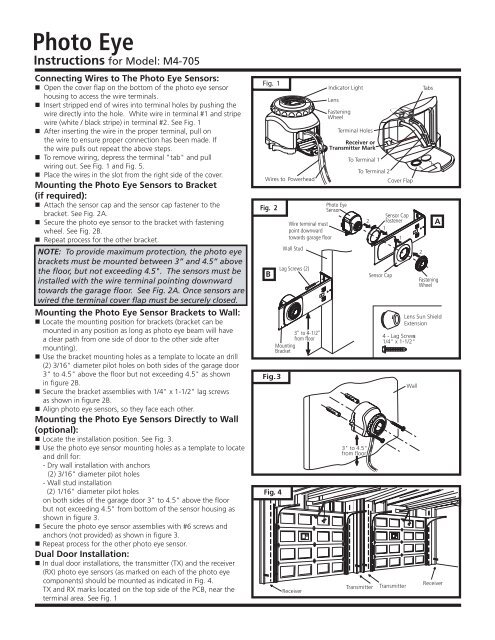
Connecting Wires to The <strong>Photo</strong> <strong>Eye</strong> Sensors:<br />
Open the cover flap on the bottom of the photo eye sensor<br />
housing to access the wire terminals.<br />
Insert stripped end of wires into terminal holes by pushing the<br />
wire directly into the hole. White wire in terminal #1 and stripe<br />
wire (white / black stripe) in terminal #2. See Fig. 1<br />
After inserting the wire in the proper terminal, pull on<br />
the wire to ensure proper connection has been made. If<br />
the wire pulls out repeat the above steps.<br />
To remove wiring, depress the terminal "tab" and pull<br />
wiring out. See Fig. 1 and Fig. 5.<br />
Place the wires in the slot from the right side of the cover.<br />
Mounting the <strong>Photo</strong> <strong>Eye</strong> Sensors to Bracket<br />
(if required):<br />
Attach the sensor cap and the sensor cap fastener to the<br />
bracket. See Fig. 2A.<br />
Secure the photo eye sensor to the bracket with fastening<br />
wheel. See Fig. 2B.<br />
Repeat process for the other bracket.<br />
NOTE: To provide maximum protection, the photo eye<br />
brackets must be mounted between 3” and 4.5” above<br />
the floor, but not exceeding 4.5". The sensors must be<br />
installed with the wire terminal pointing downward<br />
towards the garage floor. See Fig. 2A. Once sensors are<br />
wired the terminal cover flap must be securely closed.<br />
Mounting the <strong>Photo</strong> <strong>Eye</strong> Sensor Brackets to Wall:<br />
Locate the mounting position for brackets (bracket can be<br />
mounted in any position as long as photo eye beam will have<br />
a clear path from one side of door to the other side after<br />
mounting).<br />
Use the bracket mounting holes as a template to locate an drill<br />
(2) 3/16" diameter pilot holes on both sides of the garage door<br />
3" to 4.5" above the floor but not exceeding 4.5" as shown<br />
in figure 2B.<br />
Secure the bracket assemblies with 1/4" x 1-1/2" lag screws<br />
as shown in figure 2B.<br />
Align photo eye sensors, so they face each other.<br />
Mounting the <strong>Photo</strong> <strong>Eye</strong> Sensors Directly to Wall<br />
(optional):<br />
Locate the installation position. See Fig. 3.<br />
Use the photo eye sensor mounting holes as a template to locate<br />
and drill for:<br />
- Dry wall installation with anchors<br />
(2) 3/16" diameter pilot holes<br />
- Wall stud installation<br />
(2) 1/16" diameter pilot holes<br />
on both sides of the garage door 3" to 4.5" above the floor<br />
but not exceeding 4.5" from bottom of the sensor housing as<br />
shown in figure 3.<br />
Secure the photo eye sensor assemblies with #6 screws and<br />
anchors (not provided) as shown in figure 3.<br />
Repeat process for the other photo eye sensor.<br />
Dual Door Installation:<br />
In dual door installations, the transmitter (TX) and the receiver<br />
(RX) photo eye sensors (as marked on each of the photo eye<br />
components) should be mounted as indicated in Fig. 4.<br />
TX and RX marks located on the top side of the PCB, near the<br />
terminal area. See Fig. 1<br />
Fig. 1<br />
Wires to Powerhead<br />
Fig. 2<br />
B<br />
Fig. 3<br />
Fig. 4<br />
Wire terminal must<br />
point downward<br />
towards garage floor<br />
Wall Stud<br />
Lag Screws (2)<br />
3" to 4-1/2"<br />
from floor<br />
Mounting<br />
Bracket<br />
Receiver<br />
Indicator Light<br />
Lens<br />
Fastening<br />
Wheel<br />
Terminal Holes<br />
Receiver or<br />
Transmitter Mark<br />
<strong>Photo</strong> <strong>Eye</strong><br />
Sensor<br />
To Terminal 1<br />
3" to 4.5"<br />
from floor<br />
To Terminal 2<br />
2<br />
TX<br />
Sensor Cap<br />
Cover Flap<br />
Sensor Cap<br />
Fastener<br />
1<br />
4 - Lag Screws<br />
1/4" x 1-1/2"<br />
Transmitter Transmitter<br />
1<br />
Wall<br />
2<br />
Tabs<br />
1 2<br />
A<br />
Fastening<br />
Wheel<br />
Lens Sun Shield<br />
Extension<br />
Receiver
<strong>Photo</strong> <strong>Eye</strong><br />
Instructions (continued)<br />
Connecting Wires to Powerhead:<br />
Route wiring through clip on bottom of photo eye sensor holder, then run<br />
wires along the wall and the ceiling to the powerhead. Use the staples or<br />
nail clamps provided to secure wiring to the wall, joists and/or ceiling. Do<br />
not pinch wires. Drive staples or nail clamps with enough force to hold wires<br />
in place.<br />
Note: As an alternative, the wires can be routed along the top of the<br />
rail assembly, or along the outside of the door track. Be sure the wires<br />
are routed away from all moving parts of door and rail.<br />
Open the control panel cover.<br />
Feed wires through the wire guide from the top of chassis into the terminal<br />
area of control panel. See Fig. 5.<br />
Separate the double wire from each photo eye sensor into two single wires.<br />
Strip about 1/2” of insulation from the end of each of the four single wires.<br />
Combine the white wires from each photo eye sensor and twist stripped<br />
ends together tightly.<br />
Insert the stripped end of the white wire combination firmly into terminal<br />
#1 by pushing the wires directly into the terminal hole. If the wires are<br />
difficult to insert, a screwdriver may be used to depress the terminal “tab”<br />
while inserting the wires. To remove wires, depress the tab again and pull<br />
wires out.<br />
Repeat procedure for the stripe wires (white / black stripe)<br />
terminal, insert them into terminal #2.<br />
<strong>Photo</strong> <strong>Eye</strong> Sensors Alignment Procedure - Wall Bracket<br />
Mounted System:<br />
<strong>Photo</strong> eye sensors maintain an invisible, unbroken beam between each<br />
other. When the photo eye sensors are connected to the power head and<br />
the power is on, the green light on the transmitter sensor will illuminate.<br />
When the sensors are aligned, the red light on the receiver sensor will<br />
illuminate.<br />
NOTE: Additional protection for receiver sensor against severe sun light exposure<br />
In the event that further protection against severe sun light exposure to the receiver sensor is required. The<br />
external lens sunshield extension included with the photo eye sensors must be installed on the receiver sensor,<br />
ONLY AFTER THE SENSORS HAVE BEEN PROPERLY ALIGNED.<br />
The external lens sunshield extension is installed on the receiver by threading the shield extension onto the<br />
receiver fastening wheel until it bottoms out with the lens outer rim as shown in figure 7. Make sure that the<br />
external shield is FIRMLY HAND TIGHTENED ONLY, TO AVOID ANY DAMAGE TO THE SENSOR.<br />
MAKE SURE THAT ALL SYSTEM SAFETY TEST OUTLINED BY THE GARAGE DOOR OPENER MANUFACTURER<br />
ARE PERFORMED AND VERIFIED.<br />
70177 C2007<br />
All rights reserved. 07/07<br />
Fig. 5<br />
6<br />
Rotation<br />
Adjustment<br />
Fastening Wheel<br />
Wires from <strong>Photo</strong> <strong>Eye</strong>s Sensors<br />
Wire Guide<br />
Chassis<br />
To Terminal #1<br />
Terminal Holes<br />
To Terminal #2<br />
Terminal Tab<br />
Fig. 7<br />
1234 7 56<br />
Terminal ID Assignment<br />
Receiver Sensor<br />
Extension<br />
Note: Sensor alignment must be done with the door in the closed position in order to ensure proper visibility of the sensor<br />
indicator LED. Accurate alignment will ensure a high standard of safety and performance.<br />
Loosen the fastening wheel on the transmitter sensor. Place the transmitter sensor at the desire location along the wall bracket<br />
horizontal adjustment area with the sensor lens parallel to the door. Secure sensor to wall bracket.<br />
Loosen the receiver sensor fastening wheel and find the systems optimum alignment by establishing the<br />
required horizontal adjustment and rotational adjustment as shown in figure 6, until a solid red LED light appears on the receiver<br />
sensor. Secure sensor to wall bracket.<br />
If necessary, fine tune the photo eye system adjustment by loosening the fastening wheel on the receiver sensor an adjust the<br />
up/down adjustment and/or rotational adjustment, until the receiver red LED shows a solid light. The optimum alignment position is<br />
in the centre between the cut-off position in vertical plane (up/down) and in horizontal direction.<br />
Tighten the fastening wheel firmly by hand on each assembly to secure each photo eye sensor in place.<br />
If further protection against severe sun light exposure is required. Place the lens sunshied extension on the Receiver Sensor ONLY as<br />
outlined on the note below.<br />
Bracket