ASP-X2 Accelus Panel Dual - Copley Controls
ASP-X2 Accelus Panel Dual - Copley Controls
ASP-X2 Accelus Panel Dual - Copley Controls
Create successful ePaper yourself
Turn your PDF publications into a flip-book with our unique Google optimized e-Paper software.
Control Modes<br />
• Current (torque, force)<br />
DESCRIPTION<br />
<strong>Accelus</strong> <strong>Panel</strong><br />
Opto-Isolated Command Interface<br />
(per channel)<br />
• ±10V Current control input<br />
• Enable input<br />
• Buffered encoder outputs A/B/X<br />
• Digital outputs (4 total: programmable for<br />
use by either channel)<br />
Communications<br />
• RS-232<br />
Feedback<br />
• Digital Quad A/B encoder with +5V control:<br />
Incremental encoders + digital Halls<br />
Yaskawa Sigma-Mini motors<br />
Panasonic Minas-A motors<br />
Dimensions: mm [in]<br />
• 167 x 99 x 30 [6.58 x 3.9 x 1.17]<br />
<strong>ASP</strong>-<strong>X2</strong><br />
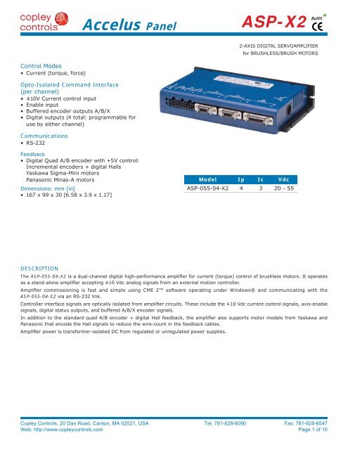
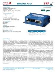
The <strong>ASP</strong>-055-04-<strong>X2</strong> is a dual-channel digital high-performance amplifier for current (torque) control of brushless motors. It operates<br />
as a stand-alone amplifier accepting ±10 Vdc analog signals from an external motion controller.<br />
Amplifier commissioning is fast and simple using CME 2 software operating under Windows® and communicating with the<br />
<strong>ASP</strong>-055-04-<strong>X2</strong> via an RS-232 link.<br />
Controller interface signals are optically isolated from amplifier circuits. These include the ±10 Vdc current control signals, axis-enable<br />
signals, digital status outputs, and buffered A/B/X encoder signals.<br />
In addition to the standard quad A/B encoder + digital Hall feedback, the amplifier also supports motor models from Yaskawa and<br />
Panasonic that encode the Hall signals to reduce the wire-count in the feedback cables.<br />
Amplifier power is transformer-isolated DC from regulated or unregulated power supplies.<br />
<strong>Copley</strong> <strong>Controls</strong>, 20 Dan Road, Canton, MA 02021, USA Tel: 781-828-8090 Fax: 781-828-6547<br />
Web: http://www.copleycontrols.com Page 1 of 10<br />
RoHS<br />
2-AXIS DIGITAL SERVOAMPLIFIER<br />
for BRUSHLESS/BRUSH MOTORS<br />
Model Ip Ic Vdc<br />
<strong>ASP</strong>-055-04-<strong>X2</strong> 4 3 20 - 55
GENERAL SPECIFICATIONS<br />
<strong>Accelus</strong> <strong>Panel</strong><br />
<strong>ASP</strong>-<strong>X2</strong><br />
Test conditions: Load = Wye connected load: 2 mH + 2 Ω line-line. Ambient temperature = 25°C, +HV = HV max<br />
MODEL <strong>ASP</strong>-055-04-<strong>X2</strong><br />
OUTPUT POWER (PER CHANNEL)<br />
Peak Current 4 (2.83) Adc (Arms), ±5%<br />
Peak time 1 Sec<br />
Continuous current 3 (2.12) Adc (Arms) per phase<br />
INPUT POWER<br />
HVmin~HVmax +20 to +55 Vdc, Transformer-isolated<br />
Input current 8.5 Adc<br />
PWM OUTPUTS<br />
Type 3-phase MOSFET inverter, 15 kHz center-weighted PWM, space-vector modulation<br />
PWM ripple frequency 30 kHz<br />
DIGITAL CONTROL<br />
Digital Control Loops Current, 100% digital loop control<br />
Sampling rate (time) Current loop: 15 kHz (66.7 µs)<br />
Commutation Sinusoidal, field-oriented control for brushless motors<br />
Modulation Center-weighted PWM with space-vector modulation<br />
Bandwidths Current loop: 2.5 kHz typical, bandwidth will vary with tuning & load inductance<br />
HV Compensation Changes in bus voltage do not affect bandwidth<br />
Minimum load inductance 200 µH line-line<br />
ISOLATED COMMAND INPUTS (PER CHANNEL)<br />
Analog torque reference ±10 Vdc, Differential, 200 kΩ impedance<br />
ISOLATED ENABLE INPUTS<br />
Number 2: One Enable input for each channel<br />
Type Opto-isolated with commoned anodes. Inputs source current into current-sinking controller outputs<br />
Voltage 24 Vdc compatible<br />
ISOLATED DIGITAL OUTPUTS<br />
Number 4: Programmable functions<br />
Type Opto-isolated NPN Darlington transistor with commoned cathodes.<br />
Outputs sink current from loads connected to +Vdc<br />
Ratings 50 mAdc max, +30 Vdc max.<br />
ISOLATED BUFFERED ENCODER OUTPUTS (PER CHANNEL)<br />
Type A/B/X digital quadrature, differential,<br />
Electrical 26C31 differential line driver<br />
ENCODER FEEDBACK (PER CHANNEL)<br />
Type A/B/X digital quadrature, differential,<br />
Yaskawa Sigma-Mini SGMM and similar models with incremental encoders<br />
Panasonic Minas-A and similar models with incremental encoders<br />
Frequency 5 MHz line frequency, or 20 Mcounts/sec after quadrature<br />
Power +5 Vdc @ 250 mA per channel. Power can be switched on/off for encoder control.<br />
Electrical 26C32 differential line receiver with 121 Ω line terminators<br />
DIGITAL HALLS FEEDBACK (PER CHANNEL)<br />
Type Hall signals, digital, single-ended, 120 degree phase difference between U-V-W<br />
Electrical 10 kΩ pull-up to +5 Vdc, 10 kΩ / 3.3 nF low-pass filter to 74HC14 Schmitt trigger<br />
RS-232 PORT<br />
Signals RxD, TxD, Gnd in 6-position, 4-contact RJ-11 style modular connector.<br />
Mode Full-duplex, serial communication port for amplifier setup and control, 9,600 to 115,200 Baud<br />
Protocol ASCII or Binary format<br />
STATUS INDICATORS<br />
Number 2<br />
Amplifier Status Bicolor LED, axis status indicated by color, and blinking or non-blinking condition<br />
PROTECTIONS<br />
HV Overvoltage +HV > HVmax, Amplifier outputs turn off until +HV < HVmax (See Input Power for HVmax)<br />
HV Undervoltage +HV < +20 Vdc, Amplifier outputs turn off until +HV > +20 Vdc<br />
Amplifier over temperature Heat plate > 70°C, Amplifier outputs turn off<br />
Short circuits Output to output, output to ground, internal PWM bridge faults<br />
I2T Current limiting Programmable: continuous current, peak current, peak time<br />
MECHANICAL & ENVIRONMENTAL<br />
Size ( mm[in] ) 167 x 99 x 30 [6.58 x 3.9 x 1.17]<br />
Weight 0.94 lb (0.43 kg)<br />
Ambient temperature 0 to +45°C operating, -40 to +85°C storage<br />
Humidity 0 to 95%, non-condensing<br />
Contaminants Pollution degree 2<br />
Environment IEC68-2: 1990<br />
<strong>Copley</strong> <strong>Controls</strong>, 20 Dan Road, Canton, MA 02021, USA Tel: 781-828-8090 Fax: 781-828-6547<br />
Web: http://www.copleycontrols.com Page 2 of 10<br />
RoHS
CME 2 SOFTWARE<br />
<strong>Accelus</strong> <strong>Panel</strong><br />
Amplifier setup is fast and easy using CME 2 software. All of<br />
the operations needed to configure the amplifier are accessible<br />
through this powerful and intuitive program. Auto-phasing of<br />
brushless motor Hall sensors and phase wires eliminates “wire<br />
and try”. Connections are made once and CME 2 does the rest<br />
thereafter. Encoder wire swapping to establish the direction of<br />
positive motion is eliminated.<br />
Motor data can be saved as .ccm files. Amplifier data is saved<br />
as .ccx files that contain all amplifier settings plus motor data.<br />
This eases system management as files can be cross-referenced<br />
to ampifiers. Once an amplifier configuration has been completed<br />
systems can be replicated easily with the same setup<br />
and performance.<br />
<strong>ASP</strong>-<strong>X2</strong><br />
RS-232 COMMUNICATIONS<br />
The <strong>ASP</strong>-055-04-<strong>X2</strong> is configured via a three-wire, full-duplex<br />
RS-232 port that operates from 9600 to 115,200 Baud. CME 2<br />
provides a graphic user interface (GUI) to set up all of the<br />
amplifierss features via a computer serial port. Connections<br />
to the RS-232 port are through J7 , an RJ-11 style connector.<br />
Signal format is full-duplex, 3-wire using RxD, TxD, and Gnd.<br />
The Serial Cable Kit (SER-CK) contains a modular cable, and an<br />
adapter that connects to a 9-pin, Sub-D serial port connector<br />
(COM1, COM2, etc.) on PC’s and compatibles.<br />
J7: RS-232 PORT<br />
<strong>Copley</strong> <strong>Controls</strong>, 20 Dan Road, Canton, MA 02021, USA Tel: 781-828-8090 Fax: 781-828-6547<br />
Web: http://www.copleycontrols.com Page 3 of 10<br />
RoHS<br />
RJ-11 style, 6 position, 4 contact<br />
Cable: 6-conductor modular type<br />
J7 SIGNAL PIN<br />
No Connect 1<br />
RxD Input 2<br />
Signal Ground 3<br />
Signal Ground 4<br />
TxD Output 5<br />
No Connect 6
AMP STATUS LED<br />
Bi-color LEDs gives the state of each axis<br />
by changing color, and either blinking or<br />
remaining solid. The possible color and blink<br />
combinations are:<br />
• Green/Solid: Axis OK and enabled.<br />
Will run in response to reference<br />
inputs.<br />
• Green/Slow-Blinking: Axis OK but<br />
NOT-enabled. Will run when enabled.<br />
• Red/Solid: Transient fault condition.<br />
Axis will resume operation when fault<br />
is removed.<br />
• Red/Blinking: Latching fault.<br />
Operation will not resume until axis is<br />
Reset<br />
Fault conditions:<br />
• Phasing error (current position<br />
is >60° electrical from Hall angle)<br />
• Short-circuits from output to output<br />
• Short-circuits from output to ground<br />
• Internal short circuits<br />
• Amplifier over-temperature<br />
Faults are programmable to be either<br />
transient or latching<br />
CURRENT CONTROL<br />
REFERENCE INPUTS<br />
Ref(+)<br />
Ref(-)<br />
100 k<br />
100 k<br />
-<br />
+<br />
<strong>Accelus</strong> <strong>Panel</strong><br />
ENABLE INPUTS<br />
[EN_COMM]<br />
[EN1]<br />
[EN2]<br />
DIGITAL OUTPUTS<br />
<strong>ASP</strong>-<strong>X2</strong><br />
<strong>Copley</strong> <strong>Controls</strong>, 20 Dan Road, Canton, MA 02021, USA Tel: 781-828-8090 Fax: 781-828-6547<br />
Web: http://www.copleycontrols.com Page 4 of 10<br />
2.49k<br />
2.49k<br />
2.00k<br />
5.1V<br />
2.00k<br />
5.1V<br />
+5V<br />
10k<br />
10k<br />
RoHS<br />
The inputs are are common-anode opto-isolators that are 24 Vdc compatible. With the<br />
[ENABLE_COMM] connected to +24 Vdc, the [EN1] or [EN2] signals are then grounded<br />
by current-sinking outputs on the controller to enable the amplifier channels.<br />
The outputs are opto-isolated NPN Darlington transistors with common emitters that<br />
can sink up to 50 mAdc from loads connected to positive voltage sources. Functions<br />
are programmable, as are the active levels (ON or OFF when True). Each output can be<br />
assigned to either axis and individually programmed to functions that include:<br />
• Amplifier fault<br />
• Motor brake<br />
• PWM sync<br />
• Program control<br />
6mA<br />
PS2802-4<br />
20<br />
[OUT1]<br />
• Custom event<br />
Axis fault<br />
Overtemperature<br />
36V<br />
Motor phasing error<br />
HV over-voltage<br />
HV under-voltage<br />
6mA<br />
PS2802-4<br />
20<br />
[OUT2]<br />
Short-circuit<br />
Current-limited<br />
Voltage-limited<br />
36V<br />
Hardware-disabled<br />
Software-disabled<br />
Motor brake active<br />
6mA<br />
PS2802-4<br />
20<br />
[OUT3]<br />
PWM outputs inactive<br />
When configured as a Custom<br />
Event, the output will go active<br />
36V<br />
when any of the events becomes<br />
true. When active, the output<br />
6mA<br />
PS2802-4<br />
20<br />
[OUT4]<br />
can be configured as on or off.<br />
The output can also be set to<br />
36V<br />
latching, or non-latching.<br />
[OUT_COMM]
GROUNDING CONSIDERATIONS<br />
AMPLIFIER ISOLATION AND GROUNDS<br />
<strong>Accelus</strong> <strong>Panel</strong><br />
Power, motor feedback, and RS-232 circuits in the amplifier share a common circuit-ground<br />
(HV Return on J1-3 & J1-6, and Signal Ground on J4-13 & J5-13). Connections to the<br />
analog reference inputs, digital inputs, and digital outputs are optically isolated from HV<br />
return. Amplifier ground should, in turn, connect to an earthing conductor at some point<br />
so that the whole system is referenced to “earth”.<br />
Because current flow through conductors produces voltage-drops across them, it is best to<br />
connect the amplifier HV Return to system earth, or circuit-common through the shortest<br />
path, and to leave the power-supply floating. In this way, the power supply (-) terminal<br />
connects to ground at the amplifier HV Return terminals, but the voltage drops across the<br />
cables will not appear at the amplifier ground, but at the power supply negative terminal<br />
where they will have less effect.<br />
Motor phase currents are balanced, but currents can flow between the PWM outputs, and<br />
the motor cable shield. To minimize the effects of these currents on nearby circuits, the<br />
cable shield should connect to Frame Gnd on the motor connectors J2-1 & J3-1.<br />
The amplifier case does not connect to any amplifier circuits. Connections to the case<br />
(Frame Ground) are provided on all of the connectors. Cables to these connectors should<br />
be shielded for CE compliance, and the shields should connect to the Frame Ground<br />
terminals. When installed, the amplifier case should connect to the system chassis. This<br />
maximizes the shielding effect of the case, and provides a path to ground for noise currents<br />
that may occur in the cable shields.<br />
For CE compliance and operator safety, the amplifier should be earthed by using external<br />
tooth lockwashers under the mounting screws. These will make contact with the aluminum<br />
chassis through the anodized finish to connect the chassis to the equipment frame<br />
ground.<br />
Signal Ground<br />
Control<br />
System<br />
±10 V<br />
Ref Input<br />
A & B<br />
Buffered<br />
Encoder<br />
Ouputs<br />
A & B<br />
Digital<br />
Inputs<br />
Digital<br />
Outputs<br />
Digital<br />
Control<br />
PWM<br />
A & B<br />
FDBK<br />
A & B<br />
RS-232<br />
Power<br />
RS-232<br />
<strong>ASP</strong>-<strong>X2</strong><br />
<strong>Copley</strong> <strong>Controls</strong>, 20 Dan Road, Canton, MA 02021, USA Tel: 781-828-8090 Fax: 781-828-6547<br />
Web: http://www.copleycontrols.com Page 5 of 10<br />
MOT A<br />
MOT B<br />
FDBK A<br />
FDBK B<br />
DC<br />
20~55 V<br />
Power Ground<br />
RoHS<br />
POWER SUPPLIES<br />
<strong>ASP</strong>-055-04-<strong>X2</strong> operates typically from<br />
transformer-isolated, unregulated DC power<br />
supplies. These should be sized such that<br />
the maximum output voltage under highline<br />
and no-load conditions does not exceed<br />
the amplifiers maximum voltage rating.<br />
Power supply rating depends on the power<br />
delivered to the load by the amplifier. In<br />
many cases, the continuous power output<br />
of the amplifier is considerably higher than<br />
the actual power required by an incremental<br />
motion application.<br />
Operation from regulated switching power<br />
supplies is possible if a diode is placed<br />
between the power supply and amplifier to<br />
prevent regenerative energy from reaching<br />
the output of the supply. If this is done,<br />
there must be external capacitance between<br />
the diode and amplifier.<br />
MOUNTING & COOLING<br />
<strong>ASP</strong>-055-04-<strong>X2</strong> has slots for mounting to<br />
panels at 0° or 90°. Cooling is by conduction<br />
from amplifier heatplate to mounting<br />
surface, or by convection to ambient.
<strong>Accelus</strong> <strong>Panel</strong><br />
MOTOR PHASE CONNECTIONS<br />
The axis outputs are three-phase PWM inverters that convert the DC buss<br />
voltage (+HV) into three sinusoidal voltage waveforms that drive the motor<br />
phase-coils. Cable should be sized for the continuous current rating of<br />
the amplifier. Motor cabling should use twisted, shielded conductors for<br />
CE compliance, and to minimize PWM noise coupling into other circuits.<br />
The motor cable shields should connect to motor frame and the amplifier<br />
frame ground terminal (J2-1 or J3-1) for best results.<br />
FEEDBACK CONNECTIONS<br />
The <strong>ASP</strong>-055-04-<strong>X2</strong> supports three types of brushless motor feedback:<br />
• Incremental encoder and digital Halls<br />
• Panasonic Midas-A incremental encoders<br />
• Yaskawa Sigma Mini incremental encoders<br />
INCREMENTAL ENCODER AND DIGITAL HALLS<br />
These CME 2 screens show the Basic<br />
Setup for a generic, incremental<br />
encoder and digital Halls motor. In<br />
this example, a 2000 line encoder<br />
is shown.<br />
ENCODER<br />
<strong>ASP</strong>-<strong>X2</strong><br />
<strong>Copley</strong> <strong>Controls</strong>, 20 Dan Road, Canton, MA 02021, USA Tel: 781-828-8090 Fax: 781-828-6547<br />
Web: http://www.copleycontrols.com Page 6 of 10<br />
HALLS<br />
= Shielded cables required<br />
for CE compliance<br />
Ch. A<br />
Ch. /A<br />
Ch. B<br />
Ch. /B<br />
Ch. X<br />
Ch. /X<br />
Hall A<br />
Hall B<br />
Hall C<br />
Encoder & Halls Vcc<br />
Encoder & Halls 0V<br />
J4, J5<br />
6<br />
A<br />
7 /A<br />
4 B<br />
5 /B<br />
2 X<br />
3 /X<br />
RoHS<br />
12 Hall U<br />
11 Hall V<br />
10 Hall W<br />
14 +5 Vdc<br />
13 Sig Gnd<br />
1 F.G.
<strong>Accelus</strong> <strong>Panel</strong><br />
YASKAWA SIGMA MINI MOTOR FEEDBACK<br />
These CME 2 screens show the Basic<br />
Setup for the Sigma Mini motors with<br />
incremental encoders.<br />
PANASONIC MINAS-A MOTOR FEEDBACK<br />
Panasonic motor Basic Setup is shown in these CME 2 screens. The encoders are<br />
2500 line, or 10,000 counts after quadrature per revolution.<br />
Panasonic Minas-A motors use an 11-wire interface that has the A & B quadrature<br />
channels, an X index channel, and a fourth RX channel that contains encoder Hall state<br />
information. As in the Yaskawa motor, the Hall data is decoded in the amplifier.<br />
ENCODER<br />
ENCODER<br />
<strong>ASP</strong>-<strong>X2</strong><br />
<strong>Copley</strong> <strong>Controls</strong>, 20 Dan Road, Canton, MA 02021, USA Tel: 781-828-8090 Fax: 781-828-6547<br />
Web: http://www.copleycontrols.com Page 7 of 10<br />
Black<br />
White/Black<br />
Yellow<br />
White/Yellow<br />
Green<br />
White/Green<br />
Red<br />
Black<br />
Green/Yel<br />
Red<br />
Pink<br />
Yellow/Green<br />
Blue<br />
Yellow<br />
Orange<br />
Light Blue<br />
Violet<br />
White<br />
Black<br />
Shield<br />
J4, J5<br />
6<br />
A<br />
7 /A<br />
4 B<br />
5 /B<br />
2 C<br />
3 /C<br />
J4, J5<br />
6<br />
A<br />
7 /A<br />
4 B<br />
5 /B<br />
2 X<br />
3 /X<br />
8 S<br />
9 /S<br />
RoHS<br />
14 +5 Vdc<br />
13 Sig Gnd<br />
1 F.G.<br />
14 +5 Vdc<br />
13 Sig Gnd<br />
1 F.G.
.080<br />
.16<br />
TYP<br />
CONNECTORS<br />
J6 SIGNAL PIN<br />
Frame Ground 1<br />
[OUT4] 2<br />
Axis A Ref(+) 3<br />
Axis A Ref(-) 4<br />
Axis B Ref(+) 5<br />
Axis B Ref(-) 6<br />
Signal Ground 7<br />
Axis A Buff Enc Out X 8<br />
Axis A Buff Enc Out /X 9<br />
Axis A Buff Enc Out B 10<br />
Axis A Buff Enc Out /B 11<br />
Axis A Buff Enc Out A 12<br />
Axis A Buff Enc Out /A 13<br />
<strong>Accelus</strong> <strong>Panel</strong><br />
167.01<br />
6.575<br />
J6 CABLE CONNECTOR:<br />
Rugged<br />
Plug: Molex 52306-2619<br />
Backshell: Molex 54331-0261<br />
Standard<br />
Plug: 3M 10126-3000VE<br />
Backshell: 3M 10326-52F0-008<br />
160.27<br />
J4 & J5 SIGNALS PIN<br />
Frame Ground 1<br />
Encoder Ch. X 2<br />
Encoder Ch. /X 3<br />
Encoder Ch. B 4<br />
Encoder Ch. /B 5<br />
Encoder Ch. A 6<br />
Encoder Ch. /A 7<br />
6.310<br />
.590<br />
Axis<br />
3.38<br />
A/B<br />
.133<br />
A<br />
B<br />
A<br />
B<br />
A/B<br />
J2 & J3 SIGNALS PIN J2 & J3 SIGNALS<br />
Motor U 3 1 Frame Ground<br />
Motor V 4 2 Motor W<br />
J1 SIGNAL PIN J1 SIGNAL<br />
Frame Ground 4 1 Frame Ground<br />
+HV 5 2 +HV<br />
Power Ground 6 3 Power Ground<br />
1<br />
13<br />
1<br />
7<br />
1<br />
7<br />
3<br />
4<br />
3<br />
4<br />
4<br />
6<br />
1.1<br />
14<br />
26<br />
8<br />
14<br />
8<br />
14<br />
1<br />
2<br />
1<br />
2<br />
J1 CABLE CONNECTOR:<br />
Shell: Molex 43025-0600<br />
Contacts (6): Molex 43030<br />
<strong>ASP</strong>-<strong>X2</strong><br />
<strong>Copley</strong> <strong>Controls</strong>, 20 Dan Road, Canton, MA 02021, USA Tel: 781-828-8090 Fax: 781-828-6547<br />
Web: http://www.copleycontrols.com Page 8 of 10<br />
1<br />
3<br />
Ref<br />
J6<br />
J5<br />
J4<br />
J3<br />
J2<br />
J1<br />
J2 & J3 CABLE CONNECTORS:<br />
Shell: Molex 43025-0400<br />
Contacts (4): Molex 43030<br />
PIN J6 SIGNAL<br />
14 [OUT1]<br />
15 [OUTPUT_COMM]<br />
16 [OUT2]<br />
17 [OUT3]<br />
18 [ENABLE_A]<br />
19 [ENABLE_B]<br />
20 [ENABLE_COMM]<br />
21 Axis B Buff Enc Out X<br />
22 Axis B Buff Enc Out /X<br />
23 Axis B Buff Enc Out B<br />
24 Axis B Buff Enc Out /B<br />
25 Axis B Buff Enc Out A<br />
26 Axis B Buff Enc Out /A<br />
PIN J4 & J5 SIGNALS<br />
8 Encoder Ch. S<br />
9 Encoder Ch. /S<br />
10 Hall W<br />
11 Hall V<br />
12 Hall U<br />
13 Power Ground<br />
14 Encoder +5 Vdc<br />
J4 & J5 CABLE CONNECTORS:<br />
Rugged<br />
Plug: Molex 54306-1419<br />
Backshell: Molex 54331-0141<br />
Standard<br />
Plug: 3M 10114-3000VE<br />
Backshell: 3M 10314-52F0-008<br />
J1,J2,J3 TOOLS:<br />
Hand Crimper:<br />
Molex 63811-2800<br />
Contact Extractor:<br />
Molex 11-03-0043<br />
RoHS
DIMENSIONS<br />
6<br />
3<br />
3 4 3 4 3<br />
1 2 1 2 1<br />
6.575<br />
6.310<br />
6.575<br />
6.310<br />
<strong>Accelus</strong> <strong>Panel</strong><br />
167.01<br />
160.27<br />
.133<br />
167.01<br />
160.27<br />
.133<br />
3.38<br />
3.38<br />
.875<br />
2.000<br />
22.23<br />
50.80<br />
.080 2.03<br />
TYP .160 4.06<br />
.590 14.99<br />
3.375<br />
1.170 29.72<br />
NOTES<br />
<strong>ASP</strong>-<strong>X2</strong><br />
1. Dimensions shown in inches (mm).<br />
85.73<br />
4.110 104.39<br />
3.904 99.16<br />
Weights:<br />
Amplifier: 0.94 lb (0.43 kg)<br />
<strong>Copley</strong> <strong>Controls</strong>, 20 Dan Road, Canton, MA 02021, USA Tel: 781-828-8090 Fax: 781-828-6547<br />
Web: http://www.copleycontrols.com Page 9 of 10<br />
RoHS
MASTER ORDERING GUIDE<br />
PART NUMBER DESCRIPTION<br />
ORDERING INSTRUCTIONS<br />
Example: Order 1 amplifier<br />
and associated components:<br />
Qty Item Remarks<br />
ACCESSORIES<br />
<strong>Accelus</strong> <strong>Panel</strong><br />
<strong>ASP</strong>-055-04-<strong>X2</strong> <strong>Dual</strong>-channel Current-mode amplifier, 55 Vdc, 3/4 A<br />
SER-CK RS-232 Cable Kit<br />
CME 2 CD with CME 2 Configuration Software<br />
1 <strong>ASP</strong>-055-04-<strong>X2</strong> <strong>Dual</strong> current-mode amplifier<br />
1 SER-CK Serial Cable Kit<br />
1 CME2 CME 2 CD<br />
PART NUMBER DESCRIPTION<br />
<strong>ASP</strong>-<strong>X2</strong>-CK Connector kit, solder cup connectors<br />
<strong>ASP</strong>-HK Heatsink kit (for field assembly, with hardware)<br />
Note: Specifications subject to change without notice<br />
<strong>ASP</strong>-<strong>X2</strong><br />
<strong>Copley</strong> <strong>Controls</strong>, 20 Dan Road, Canton, MA 02021, USA Tel: 781-828-8090 Fax: 781-828-6547<br />
Web: http://www.copleycontrols.com Page 10 of 10<br />
RoHS<br />
Rev 4.01_TU 11/29/2011


