ESV.Eleventh.Int.Conf.SECTION.FOUR.Session.Eight
ESV.Eleventh.Int.Conf.SECTION.FOUR.Session.Eight
ESV.Eleventh.Int.Conf.SECTION.FOUR.Session.Eight

You also want an ePaper? Increase the reach of your titles
YUMPU automatically turns print PDFs into web optimized ePapers that Google loves.
Technical <strong>Session</strong> <strong>Eight</strong><br />
Motorcycle Safety<br />
Development of a Safety Concept for Motorcycles-Results From Accident<br />
Analysis and Crash Tests<br />
A. Sporner,<br />
K. Langwieder,<br />
J. Polauke,<br />
HUK-Verband,<br />
Automobile Engineering Department,<br />
Federal Republic of Germany<br />
Abstract<br />
The high proportion of seriously injured per$ons<br />
and fatalities in traffic accidents involving motorcycles<br />
makes it clear that the protection of the motorcyclist<br />
is still not satisfactory. Since the middle of the<br />
Seventies it has therefore been an objective of acci.<br />
dent research to reduce the injury risk of the motorcycle<br />
driver. By way of introduction, a survey is given<br />
of the current studies in Cermany and abroad for<br />
improving motorcycle safety and of the different<br />
concept$.<br />
The accident analyses, crash tests and mathematical<br />
simulations, carried out by the HUK-Verband,<br />
showed that the most important objective in reduciug<br />
the severity of injuries is the optimization of the path<br />
of movement of a motorcyclist involved in an accident.<br />
Findings with regard to single vehicle accidents<br />
and with regard to the different collision types, if a<br />
motorcycle collides with another vehicle, are presented.<br />
It can be seen that in both the accident in which no<br />
other vehicle was involved and in the different<br />
motorcycle/car-collision types, the reduced accident<br />
severity of the motorcyclist resulted from the controlled<br />
separation from his machine. This can be<br />
influenced by constructive measure$, such a$, for<br />
example, knee-pads, optimized tank and handle-bar<br />
designs, additional construction elements and possibly<br />
by an airbag in front of the motorcyclist.<br />
Proposals for such safety designs are presented and<br />
their possible effects are estimated and discussed. On<br />
the basis of these scientific results questions relating<br />
to the practical application are dealt with,<br />
<strong>Int</strong>roduction<br />
"Motorcycling has got safer," the motorcycle magazines<br />
in the Federal Republic of Cermany announce,<br />
referring to the decline in the accident figures that can<br />
be observed in the last few years. A look at these<br />
figures, even in relation to the registrations, confirms<br />
this statement /l/.<br />
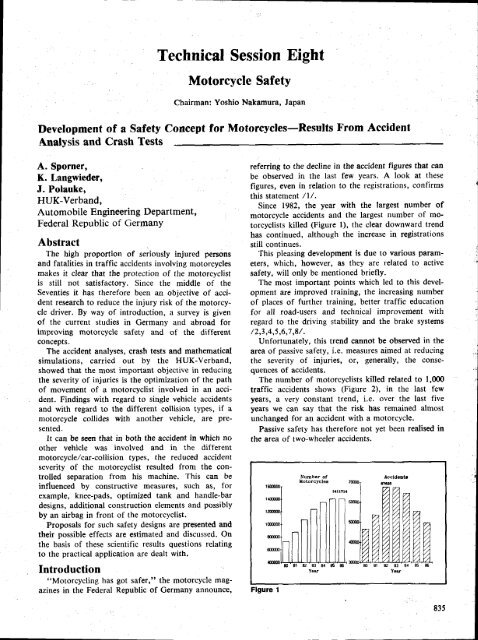
Since 1982, the year with the largest number of<br />
motorcycle accidents and the largest uumber of motorcyclists<br />
killed (Figure l), the clear downward trend<br />
has continued, although the increase in registrations<br />
still continues.<br />
This pleasing development is due to various parameters,<br />
which, however, as they are related to active<br />
safety, will only be mentioned briefly.<br />
The most important points which led to this development<br />
are improved training, the increasing number<br />
of places of further training, better traffic education<br />
f
ill<br />
?5<br />
m<br />
t5<br />
Flgure 2<br />
Klllad Motoroyollete prr tO00 Anctdeqtg<br />
83<br />
Year<br />
Man-Vehicle-Hnvironment<br />
A safety concept lbr motorcycles must cover all<br />
areas of the road traffic (Figure 3). This means that<br />
passive safety must also bc related to<br />
"Man"<br />
the areas<br />
and "Environment"<br />
and must not deal solelv<br />
with the ('Vehicle".<br />
Safety element.s in the area ..Man" relate mainly to<br />
the protective clothing and the crash helmet.<br />
The most recent developments in this field show a<br />
clear increase in safety compared to the protective<br />
suits of only 5 to l0 years /g,l0,ll/.<br />
One of the new materials, a special foam substance,<br />
only mcntioned here as one example, is worked into<br />
the suit and thus increases the protective effect in the<br />
event of the direct application of force /13/. At the<br />
same time, however, movernent is not impaired, so<br />
that these additional protective plates do not have a<br />
negative effect on active safety.<br />
In the area "Environment" passive safety must<br />
concentrate, first and foremost, on neutralising ag_<br />
gressive obstacles at the side of the road /14,15 /, but<br />
further improvements still have to be worked out for<br />
the other road-users /16,/.<br />
ffi<br />
EXPERIMENTAL SAFETY VEHICLES<br />
Figure 3 Figure 4<br />
836<br />
\<br />
The most recent work in this field shows a construction<br />
with which the posts of guardrails can be<br />
enclosed. This reduces the impact against the guard_<br />
rail posts, which often results in critical injuries and<br />
amputations.<br />
Arranging the rest of the road demarcations with<br />
the motorcyclist in mind and neutralising the accident<br />
opponent's vehicle contours are also elements of<br />
importance in this area.<br />
There remains the vehicle itself, which in the last 30<br />
years has undergone hardly any changes as far as<br />
passive safety is concerned.<br />
But the prerequisite for the development of a safety<br />
concept for motorcycles is the knowledge of how<br />
accidents happen, i.e. the motorcyclist's extremely<br />
different movement sequences as they occur in motor_<br />
cycle accidents and the chances of injury which these<br />
involve have first to be analysed /17/.<br />
Accident Systematic and Injury<br />
Distribution<br />
A classification system which should be capable of<br />
describing a// the possible motorcycle accidents does<br />
not work because of the large number of possible<br />
accident sequences and,/or kinds of movements. For<br />
this reason it has proved practicable to divide up the<br />
ways in which motorised two-wheelers are involved in<br />
accidents into four main accident groups (Figure 4)<br />
which make a fundamental distinction in the ways in<br />
which the injuries arise hut allow variations within the<br />
group /18/. These accident groups are:<br />
r side collision (the motorcycle<br />
is hit)<br />
r frontal collision (the motorcycle hits another<br />
vehicle with its front)<br />
r grazing collision<br />
r single accident<br />
The first division is into sirrgle accidents and<br />
collisions. The collision groups themselves must be
subdivided into three different movement sequences,<br />
because a combined assessment of these accidents tell<br />
us nothing c-learly about how the injuries arise.<br />
The frequency of these accident groups (Figure 5)<br />
$hows that the collision of a motorcycle with another<br />
road-user dominates.<br />
A large number of undetected cases must be expected<br />
in the proportion of single accidents, since<br />
many of these accidents are not recorded by the police<br />
or by an insurance company. This is the only possible<br />
explanation for the fact that about one-third of all<br />
motorcycli$ts killed-this figure has remained constant<br />
over the last few years-lost their lives in single<br />
accidents, although the proportion of single accidents<br />
never exceeds about 2090 in all the material /l/.<br />
In the distribution of the injuries related to the two<br />
collision types "frontal- and side collision" (Figure 6)<br />
it can be seen that the proportion of injuries to the<br />
lower extremities come first and are nearly equal. The<br />
difference of these two accident groups is shown by<br />
the injuries of the head. For the frontal collision it is<br />
therefore the main aim to reduce the risk of head<br />
injuries.<br />
Cenerally you can say, that the injury risk for a<br />
motorcycle-user is lower when he is engaged in a<br />
side-collisir:n. In a frontal-collision, in nearly every<br />
body region the frequency of injury is higher.<br />
Realisation of Safety Concepts<br />
The frequency of the last-mentioned accident<br />
group, the severitiy of injury within this group and<br />
the possibility of constructively working our improve-<br />
ments for this accident group, were, at the beginning<br />
of the research work in the two-wheeler sector, the<br />
reasons for concentrating on this accident group alone<br />
/20/.<br />
In the meantime improvements and new safety<br />
elements have also been developed for the remaining<br />
accident groups and they will be presented below. tsut<br />
in the practir"-al application ol' the safety elements<br />
developed it is important that a safety element which<br />
works well in one accident group should by no means<br />
Flgure s<br />
Dlstrlbution ot th€ Mdln-Accldent-Groupt<br />
Yotorcycl.r oyor 60 cqE<br />
<strong>SECTION</strong> 4. TECHNICAL SESSIONS<br />
tr 8fif,*n"<br />
@ Sltlo-<br />
Collielon<br />
[J Frontal-<br />
Collislou<br />
I<br />
Stnele-<br />
Vehicle-<br />
Accident<br />
Itl.trlbuuoa Ol It. IDJurt{ ll l\ro Ilufcrrrt lqoldoEt CfouDl<br />
@ L_!Ed{.d Et*l thtr|N orr-r I<br />
tfsd - r0,rr - tl.6r<br />
xel - 6.a 7<br />
frodd.r _ 6.3 I + 16,2x<br />
DrN't-h- s.7* - 9,6t<br />
UFFIE<br />
-<br />
6.5r<br />
-<br />
a.tl<br />
loil lE<br />
.+<br />
e.? t - 16,5 i<br />
SDlu 4 EBI - 0.6x<br />
HEtl + 16.7t - lC.Sl<br />
lldffi I - ll.4x<br />
tuah - Lz,6 t - 19.0t<br />
rrn - 16.?r - 5t.Er<br />
l+u la - eo,A t - S,6 i<br />
r@t - 16.lI - 17,9 I<br />
Flgure 6<br />
have negative effects on oRe of the other accident<br />
groups. On the one hand, this special search for<br />
safety elements and, on the other hand, comprehensive<br />
knowledge of the overall two-wheeler's accident<br />
picture has led to the development of a concept, some<br />
of the main features of which have already been taken<br />
up by the manufacturers.<br />
Directions of Passive Safety<br />
So how can the motorcyclist's injury risk be reduced?<br />
In recent times two directions (Figure 7) have<br />
taken shape, both of which aim at reducing injuries<br />
but which go fundamentally different ways.<br />
One of these directions is concerned with the<br />
possibility of influencing the movement path of the<br />
motorcyclist, so that dangerous contacts with his<br />
motorcycle and/or with the accident opponent can be<br />
avoided. This direction concentrates on avoiding the<br />
motorcyclist becoming entangled with his own machine<br />
and on deflecting the body when impact with an<br />
obstacle occurs.<br />
ln the second case, the motorcyclist should be held<br />
more firmly in positiorr by creating a restraint system<br />
which, similar to the one used for car occupants,<br />
passes on a tolerable deceleration resulting from the<br />
design of the machine to the driver.<br />
The practical solution provides for a safety belt or<br />
knee pads in front of the driver's chest /21,22,23/.<br />
Flgure 7<br />
MOTORCYCTE SATBIY<br />
-F<br />
-\<br />
Restralnt Optlrnlzing The<br />
Motion PatJr<br />
837
A prerequisite for this equipment to work is the<br />
controlled speed reduction by an appropriate design<br />
of a deformable zone. But this is not possible with a<br />
normal motorcycle, since the design of the motorcycle<br />
would have to be fundamentally changed if a restraint<br />
device of this kind is to fulfill its purpose.<br />
An example (Figure 8) of what this may look like in<br />
reality was presented at the last <strong>ESV</strong>-<strong>Conf</strong>erence in<br />
the fringe programme two years ago and with this<br />
kind of vehicle a gain in safety by using a safety belt<br />
is within the bounds of possibility, but for the normal<br />
construction of a motorcycle the idea of a safety belt<br />
should not be pursued any further.<br />
Influencing the flight path, that is the second<br />
possibility of realising a passive safety concept for the<br />
motorcycle, can be integrated into the present-day<br />
design of a motorcycle.<br />
Frontal Collisions<br />
0ptimizing the motion Path<br />
The basis of this concept was the result of studies<br />
which showed that, in comparable accidents, i.e.<br />
collisions in which a motorcyle runs into an accident<br />
opponent, the motorcyclists were injured least severely<br />
when they were able to "fly over" lheir accident<br />
opponent /24,25,26/. This may take place completely<br />
or partially; in any event the direct impact of the head<br />
against the car must be avoided.<br />
The evaluation of these accidcnts shows that the<br />
severity of injury in the case of g "fly-over" was, in<br />
every speed range, below the injury severity of the<br />
motorcyclist who irnpacted directly with the accident<br />
opponent.<br />
A comparison of the injuries to the individual parts<br />
of the body (Figure 9), broken down according to<br />
"fly-over" and<br />
"impact", also makes it clear that the<br />
frequency of the $eriou$ head injuries decreases in the<br />
case of g'ofly-overt'.<br />
Figure E<br />
838<br />
EXPERIMENTAL SAFETY VEHICLES<br />
,ry<br />
IM<br />
HGid<br />
ilsct<br />
Sbould€r<br />
Br€ast-An-<br />
Uppuh<br />
Fqr.lm<br />
8pl$<br />
Hmd<br />
lMod6<br />
frth<br />
Itdrr<br />
LmrLl<br />
tmt<br />
Flgure I<br />
Illstrlbutlotr Ol The lDjurler ID Dttldrsnt Uqtion Sequ6Dc.t<br />
-<br />
-<br />
-<br />
-<br />
With the lower extremities, the differences are not<br />
as clear. This is due to the fact that' even in the case<br />
of a "fly-over" the motorcyclist's legs can be caught<br />
on the handlebars or can graze the accident opponent<br />
if there is no knee-pad.<br />
First proposfll for fl safer motorcycle<br />
The findings of the analyses mentioned of real-life<br />
accidents were tested and confirmed by us by means<br />
of experimental simulation and mathematical calculations.<br />
This first test serie (Figure l0) was already presented<br />
at the last <strong>ESV</strong> <strong>Conf</strong>erence, and, as a result of<br />
these experiments, a sal'ety mototcycle /27 / was<br />
presented which possessed the following additional<br />
and/or altered characteristics.<br />
By combining knee-pads in frotrt of the legs of the<br />
driver with a touring handlebar it was possible, on the<br />
one hand, for the driver to avoid leg contact with his<br />
own handlebar and the accident opponent and, at the<br />
same time, to reduce a direct impact of the head<br />
against the edge of a car's roof by means of an<br />
Flgure 10<br />
16%<br />
47<br />
ax<br />
LZ<br />
t0I<br />
42fr<br />
281<br />
6E<br />
7E<br />
taE<br />
28fr<br />
l3x<br />
e0E<br />
368<br />
311<br />
?0x<br />
lfr<br />
IF<br />
tfr<br />
4fi<br />
3fr<br />
7E
upright sitting position. On impact the motorcyclist<br />
did not become entangled in his machine and the<br />
prerequisite for a "fly-over" with reduced injury risk<br />
was created. This concept is supported by a ramp-like<br />
design of the tank, since it is the lower part of the<br />
driver's body which first strikes this part of the<br />
machine after a pause of about 30 ms. Raising the<br />
seat also results in further advantages, but it is in<br />
contradiction to considerations of driving dynamics,<br />
since the position of the c€ntre of gravity has an<br />
effect on the handling of the motorcycle. A suggestion<br />
proposed by us at that time was to design the seat<br />
with a variable height, so that even drivers of different<br />
physiques would be able to handle one and the<br />
same motorcycle ideally.<br />
A further, although very small, contribution,<br />
namely to take the head away from the accident<br />
opponent's danger zone, can be made by an anti-dive<br />
system, when, during an emergency braking, the<br />
dipping of the front wheel fork and thus the lowering<br />
of the body are avoided. Even the few centrimetres<br />
thus gained in height can be decisive for the severity<br />
of the injuries.<br />
These measures that were proposed were the first<br />
step towards optimizing the driver's movement path;<br />
but it also became clear that a direct impact could not<br />
be completely avoided. For this reason the possibility<br />
of the motorcyclist actively inducing his flight parh by<br />
bringing his body into the uprighf position shorrly<br />
before the collision was also pointed out. That is, of<br />
course, not possible in all cases, and this is the reason<br />
why a closer study was made of another safety<br />
element which up to now has only made an appearance<br />
in the car sector, the airbag.<br />
The airbag could, under circumstances (Figure ll),<br />
perform a function within the safety elements of the<br />
motorcycle as well. The most important prerequisite<br />
is, however, that the airbag is not conceived as a<br />
re$traint system, but that its function is also extended<br />
to include the influencing of the flight path.<br />
The first tests with airbags on the motorcycle go<br />
back 15 years and unfortunately nothing is known<br />
about a continuation of this work. It was not until<br />
1985 at the <strong>ESV</strong> <strong>Conf</strong>erence in Oxford that two<br />
proposals for a "two-wheeler-airbag" was published<br />
/29,30/, one of the contributions being based on a<br />
test series by our office. This test series has, in the<br />
Flgure 11<br />
Furction Of A Motorcysle Alrbag<br />
Cushioning lbe Impact<br />
Inlluence On lbe Flight Path<br />
<strong>SECTION</strong> 4. TECHNICAL SESSIONS<br />
meantime, been continued and its findings can be<br />
summed up as follows.<br />
Experiments were carried out with and without the<br />
airbag on a sledge facility, which allows the simulation<br />
of the simplified cause of a collision.<br />
The motion sequence without an airbag (Figure 12)<br />
shows the direct impact against the simulated obstacle.<br />
The dummy's head smashes into the obstacle in<br />
the area of the visor's opening and at the same time<br />
its legs are caught up on the handlebar.<br />
The same experience with an airbag and a knee-pad<br />
(Figure 13) clearly shows that no contact takes place<br />
between the head and the obstacle and that the<br />
motion path of the dummy is reflected upwards. This<br />
test series was made at a speed of 40 km/h, and at<br />
higher speeds it is to be assumed that the component<br />
of the dummy's upward direction of movement will<br />
be shifted further forward.<br />
In the case of a frontal impact therefore a safety<br />
effect of the airbag can be observed. The problems<br />
which have still to be overcome thus concentrate on<br />
the economic feasibility, since the technical realisation<br />
of the triggering device still requires extensive work.<br />
In this connection the question of the all-mechanical<br />
airbag /31/ also has to be discussed, which in an<br />
amazingly simple way makes the ignition of the airbag<br />
a purely mechanical problem, without electrical sensofs.<br />
Nevertheless, there are still some problems to be<br />
solved, the following points being of paramount<br />
importance:<br />
. triggeringreliability<br />
. sensor development<br />
. economy,<br />
^, ^<br />
Flgure 12<br />
1o rnr<br />
-r*-.<br />
1^^ a a ^ ^1 f^ i"r i<br />
t...,<br />
. . | | | r :-*j'.\.<br />
Drrmmy Motion rithout Airbag<br />
40 I@/h Collision Speed
^l.<br />
^^^<br />
Figure 13<br />
a ^ ^ ^<br />
I r r<br />
t<br />
t<br />
l<br />
1O tnn<br />
^1, ^f^<br />
r t t !<br />
Dummy Motion ritJr Airbag<br />
40 lm/h Colllslon Speed<br />
The usefulness of crash sensors on the basis of a<br />
special sound emission when the front wheel fork is<br />
bent is at present being examined by us. Combined<br />
with a normal deceleration element, this triggering<br />
mechanism could, under circumstances, meet the high<br />
demands required in the case of the motorcycle.<br />
Single Accidents<br />
For the remaining accident groups it has already<br />
been stated that the injury risk of the lower extrcmities<br />
comes first. At the $ame time it also applies to<br />
these accident groups that the injury risk of the whole<br />
body can be reduced if there is a separation of the<br />
motorcyclist from his machine. In the accident group<br />
termed "single accident" a new possibility of helping<br />
this separation to take place has emerged. By analysing<br />
300 single accidents it was shown that a positive<br />
turning movement (positive spin) of the motorcycle<br />
(Figure 14) that has fallen over, i.e. when the motorcycle<br />
continues to turn in the curve through which it<br />
is driving, helps to bring about a separation of driver<br />
and machine /32,2.<br />
If a negative turn takes place (negative spin) and<br />
the motorcyclist cannot separate himself from his<br />
machine and he is deflected into the path of oncoming<br />
traffic together with the motorcycle and may<br />
thus become endangered by the on-coming traffic.<br />
In a subsequent experimental and mathcmatical<br />
simulation it was possible to define special friction<br />
areas which have an effect on the turning movement<br />
of the skidding motorcycle.<br />
840<br />
EXPERIMENTAL SAFETY VEHICLES<br />
)--* \<br />
{*1*H---*il- d4<br />
Figure 14<br />
Thus an area with the highest possible friction<br />
values in the region above the motorcycle's centre of<br />
gravity in combination with an area with a low<br />
friction value below the centre of gravity produce the<br />
best conditions for a positive turning movement.<br />
These friction areas could be integrated relatively<br />
unobtrusively into a motorcycle by means of the<br />
covering panels. ln addition to this, howevet, the<br />
footrests, gearchange and brake would also have to be<br />
modilied somewhat in their design, so that the antifriction<br />
properties are improved.<br />
At any rate, this development shows that by means<br />
of systematic analysis solutions can always be worked<br />
out which result in a further step towards passive<br />
safety.<br />
Grazing Collision and Side Collision<br />
With the last two accident group$ it becomes clear<br />
how endangered the lower extremities of the motorcyclist<br />
are. In the case of these accident groups any<br />
contact is aimed at the area above the footrests up to<br />
about the level of the tank. While most grazing<br />
collisions lead to serious smashing of the knee or<br />
amputations, in the case of side collisions for the<br />
most part bruises and fractures can be observed. A<br />
safety concept for these groups has to overcome, first<br />
of all, the limited possibility of working out any<br />
design improvemcnts.<br />
Although the protective cages some people have<br />
proposed /33/ do help, they turn the motorcycle into
a specialised vehicle once again. The only feasible way<br />
is to strengthen the covering panels, if a knee pad is<br />
already in place in front of the legs, in combination<br />
with an additional strengthening of the side bags. The<br />
protective space thus gained has, above a certain<br />
impact speed, no longer any function, but it certainly<br />
helps in all cases in which slight to medium injuries<br />
are nowadays still sustained /34,35/.<br />
Summary<br />
A safety concept for motorcycles must cover all<br />
areas of the traffic scene. Measures taken with the<br />
motorcyclist, such as improved protective suits and<br />
helmets, adapting the environment by neutralising<br />
dangerous road demarcations and aggressive accident<br />
opponents and optimizing the motorcycle itself result<br />
in a reduction of the injury risk. In this connection it<br />
is absolutely essential to divide up the different<br />
sequences in order to work out how the injuries arise.<br />
A synthesis of the proposed safety elements of the<br />
individual accident groups, whilc observing the rule<br />
that no negative effects on the neighbouring groups<br />
can be observed, results in a safety concept for a<br />
motorcycle (Figure 15) which constitutes a clear gain<br />
in passive safety.<br />
Depending on the accident groups, the chances of<br />
success in reducing the injury risk can be recognized.<br />
The greatest prospects of success will come about in<br />
the case of frontal collisions of motorcycles, since<br />
here the design elements can show the greatest effect.<br />
Making it possible for the motorcyclist and his<br />
machine to be separated and to overcome the obstacle-both<br />
of these actions involving a low injury<br />
risk-shows the greatest chances of success.<br />
In the remaining accident groups it is always the<br />
impact energy of the accident opponent and/or the<br />
post-crash movement in the case of a fall which<br />
decides the final injury pattern. It is very difficult to<br />
influence these parameters by taking measure$ to<br />
change the usual design of the motorcycle.<br />
|I""'*"**-' I<br />
I sd hs Padr<br />
E arbd8.syfr.m<br />
I<br />
3 shipE $t runlis\k<br />
I<br />
{ f sG ol Hlrh Frtdton<br />
I<br />
6 vMlibl. H.IBht<br />
I<br />
|<br />
I<br />
I<br />
I<br />
I<br />
I<br />
6 k.r ol br Fdcttor I<br />
z stae rrouctron<br />
I<br />
6 hri- pk. .syd.b<br />
I<br />
I<br />
I<br />
Figure 15<br />
<strong>SECTION</strong> 4. TECHNICAL SESSIONS<br />
References:'":<br />
l. Statistisches Bundesamt Wiesbaden;<br />
Stra0enverkehrsunfiille. Wiesbaden, Dezember<br />
1986<br />
Z. StraBenverkehrsrecht der Bundesrepublik<br />
Deutschland, Gesetz iiber das Fahrlehrerwesen<br />
(Fahrlehrergesetz), Bundesverkehrsministerium,<br />
Durchfiihrungsverordnung letzte Fassung l2185<br />
3. Funfte Verordnung zur Anderung<br />
straBenverkehrsrechtlicher Vorschriften; Bundesgesetzblatt,<br />
13. Dezember 1985, Teil l, Jahrgang<br />
1985. Seite 2276 ff.<br />
4. DVR-Zwciradtraining, Vom Mofa bis zurn<br />
Leichtkraftrad, Ein Fortbildungsprogramm des<br />
Deutschen Verkehrssicherheitsrates und seiner<br />
Milglieder<br />
5. Bayer, 8., Das Pendeln und Flattern von Kraftrf,dern;<br />
Institut fiir Zweiradsicherheit e,V., Bochum<br />
1986<br />
6. Hackenberg, U., Ein Beitrag zur Stabilitdtsuntersuchung<br />
des Systems<br />
"Fahrer-Kraftrad-StraBe";<br />
Technische Hochschule Aachen, Diss., Aachen<br />
1985<br />
7. BMW AG', Miinchen; Erstes Motorrad-ABS;<br />
Vorstellung des Motorrad-ABS anlii$lich der<br />
IFMA 1986<br />
8. Hydromechanik allein als Blockierschutz; Automatischer<br />
Blockierverhinderer ohne Elektronik-<br />
Fiir Fronttriebler und Motorrdder;<br />
VDl-Nachrichten Nr. 24, Technik, 14. Juni 1985<br />
9. Danner, M., Langwicder, K., Polauke J.,<br />
Sporner, A., Schutzkleidung fiir motorisierte<br />
Zweiradfahrer, Bundesanstalt fiir Stradenwesen,<br />
Dezember 1984<br />
10. Stcicker, U., L
nutzer; Institut fiir Zweiradsicherheit e.V., Sept.<br />
1984<br />
15. Jessl, P., Anprallversuche an Leitplanken mit<br />
Dummies; Institut ftir Zweiradsicherheit e.V., 2.<br />
Bochumer Workshop zur Zweiradsicherheit, Bochum<br />
1986<br />
16. CauF, F., Langwieder, K., Schmidt, W.D.,<br />
Wrobel, M., Aupere Sicherheit von Lkw und<br />
Anhdngern; Forschungsvereinigung Automobiltechnik<br />
e.V., Frankfurt/M. Dezember 1982<br />
17. Langwieder, K. Collision Characteristics and Injuries<br />
to Motorcyclists and Moped Drivers; 21.<br />
Stapp Car Crash <strong>Conf</strong>erence, New Orleans 1977<br />
t8. Langwieder, K., Sporner, A., Polauke, J., Ansatzpunkte<br />
zur Erhohung der passiven Sicher'<br />
heit-Erkenntnisse der Unfallforschung; VDI-<br />
Cesellschaft Fahrzeugtechnik, 100 Jahre Motorrad,<br />
Miinchen Oktober 1985<br />
19. Hurt, H.H., Quellet, J.V., Thom, D.R., Motorcycle<br />
Accident Couse Factors and Identification<br />
of Countermeasures; National Highway Traffic<br />
Safety Administration, Washington January<br />
t98t<br />
20. Seidl, J., Experimentelle Parametervariationen<br />
fiir Motorradkollisionen; HUK-Verband,/Allianz-<br />
, Zentrum fiir Technik, Diplomarbeit, Mtinchen<br />
l98t<br />
21. warson Patentschrift Nr. 2836981/B60R2l/00<br />
22. Schimmelpfenning, K.-H., Diskussionsbeitrag<br />
zur passiven Sicherheit von Motorrddern; Kolloquium<br />
"Sicherheit bei motorisierten Zweirddern",<br />
Verlag TuV-Rneinland, Seite 2'76-278,<br />
Kriln 1981<br />
23, Diskussionsbeitrag zum Thema "Feet Forward'n<br />
bei der 10. <strong>ESV</strong>-<strong>Conf</strong>erence, Oxford 1985<br />
24. Grandel, J., Schaper, D., Impact Dynamic,<br />
Head Impact Severity and Helmet's Energy Absorption<br />
in Motorcycle/Passenger Car Accident<br />
Tests; <strong>Int</strong>ernational IRCOBI <strong>Conf</strong>erence, Delft<br />
r984<br />
25. Lindemann, Grandel" Berg, F.A., Colli'<br />
EXPERIMENTALSAFETY<br />
VEHICLES<br />
sion Dynamics in Experimental Simulations of<br />
90' Motorcycle Collisions against the Side of<br />
Moving Passenger Cars; lnternational IRCOBI<br />
<strong>Conf</strong>erence, Ziirich 1986<br />
26. Sporner, A., Experimentelle und mathematische<br />
Simulation von Motorradkollisionen im Vergleich<br />
zum realen; Unfallgeschehen Technische<br />
Universitdt Miinchen, Diss., Miinchen 1982<br />
27. Sporner, A., Erkenntnisse aus der Zweiradunfallforschung-Mtiglichkeiten<br />
einer Sicherheitskonstruktion<br />
fiir Motorrflder; Institut fiir Zweiradsicherheit<br />
e.V., 1. Bochumer Workshop,<br />
Bochum 1983<br />
28. Hirsch, A.8., Bothwell, P., Air Bag Crash<br />
Protection for Motorcycle Application; NHTSA,<br />
ASME-Paper 1971<br />
29. Chinn, 8.P., G.L. Donne, P.D. Hopes, Motorcycle<br />
Rider Protection In Frontal Impacts; 10.<br />
<strong>ESV</strong> <strong>Conf</strong>erence, Oxford 1985<br />
30. Danner, M., Langwieder, K., Sporner, A., Acci<br />
dents of Motorcyclists, lncrease of Safety by<br />
Technical Measures on the Basis of Krtowledge<br />
derived from Real-Life Accidents; <strong>Int</strong>ernational<br />
<strong>ESV</strong>-<strong>Conf</strong>erence. Oxlord 1985<br />
31. Breed, A., Can We Develop Less Expensive<br />
Airbags; SAE Paper 851201, May 1985<br />
32. Lechner. M. Der Zweirad-Alleinunfall-Relation<br />
zwischen realem Unfall, Versuch und mathematischer<br />
Simulation: Allianz-Zentrum fiir<br />
Technik, Technische Universitdt Miinchen, Diss.,<br />
Miinchen 1986<br />
33. P. Bothwell, Motorcycle and Recreational Vehicle<br />
Safety; Second <strong>Int</strong>ernational Congress On<br />
Automotive Safety, Paper No. 73016, San Francisco<br />
1973<br />
34.<br />
Chinn, 8.P., Hopes, P., Leg Protection for<br />
Riders of Motorcycles; Transport and Road<br />
Research Laboratory, <strong>ESV</strong> 1985<br />
35. Tadokoro, H., Fukuda, S., Miyazaki, K., A<br />
Study of Motorcycle Leg Protection; Japan Automobil<br />
Research Institute, Japan, <strong>ESV</strong> 1985
<strong>SECTION</strong> 4. TECHNICAL SESSIONS<br />
A Study on Methods of Measuring Fields of View of Motoreycle Rearview<br />
Mirrors<br />
Masnnori Motoki,<br />
Japan Automobile Research Institute, fnc.,<br />
Tsuneo Tsukisaka,<br />
Japan Automobile Manufacturers Assn.,<br />
Inc.,<br />
Japan<br />
Abstract<br />
This study involved 26 American motorcycle riders<br />
in an effbrt to establish measurement methods of<br />
rearward field of view of motorcycle rearview mirrors.<br />
A survey of rear-view mirror aiming, measurements of<br />
rider arm contour and computer simulations of rearward<br />
field of view were part of the study.<br />
l. The survey of rear-view mirror aiming was<br />
carried out by checking the adjustments that<br />
the test riders had made on the test motorcycle<br />
with fairing mounted rear-view mirrors<br />
and on their own motorcycles. The results<br />
indicated that, to measure the rearward field<br />
of view, the rear-view mirrors should be<br />
adjusted at an angle where a light beam<br />
travelling from reference eye-point to mirror<br />
center was reflected in a horizontal and<br />
parallel manner to vehicle center line.<br />
2. Arm contour was measured by taking photographs<br />
from the top and the side of the<br />
shoulder and arms of riders seated on two<br />
types of motorcycle mock-ups, Results<br />
showed that arm line was the significant<br />
factor in determining rider arm shadow.<br />
3. Computer simulations of rearward field of<br />
view was conducted for three types of motorcycles.<br />
This resulted in a computer simulation<br />
program to examine the rearward field<br />
of view of motorcycle rear-view mirrors and<br />
measurement methods when using a threedimensional<br />
manikin for motorcycles placed<br />
on motorcycle.<br />
<strong>Int</strong>roduction<br />
A method for measuring the rearward field of view<br />
is a precondition for examining the de$ign requirement<br />
(i.e. rear-view mirror curvature, size and mounting<br />
position) and the performance requirements (field<br />
of view reference) that determine the field of view of<br />
motorcycle rear-view mirrors.<br />
In order to estahlish measurement method of rearward<br />
field of view of motorcycle rear-view mirror, it<br />
is necessary to determine the followng items.<br />
l. Method of eye point determination as a<br />
reference point for field of view measuremenl.<br />
2. Method of mirror aiming determination for<br />
. selection of field of view.<br />
3. Method of arm contour determination that<br />
prescribes inner field of view.<br />
The method to establish eye point which is reference<br />
point for the field of view of rear*view mirror<br />
for motorcycle, and the development of the threedimensional<br />
manikin for motorcycle which was necessary<br />
for the determination of eye point on the actual<br />
vehicle were reported based on the data of 155<br />
American motorcycle riders at The l0th <strong>Int</strong>ernational<br />
Technical <strong>Conf</strong>erence on Experimental Safety Vehicles<br />
(Motoki & Asoh, 1985).<br />
In order to use a manikin for measuring the<br />
rearward field of view of motorcycle rear-view mirrors<br />
and the method of determining arm contour had to be<br />
established.<br />
Thus a survey was conducted to examine the<br />
rear-view mirror aiming methods of American motorcycle<br />
riders. Photographic measurements t.rom the top<br />
and side were made of arm configurations of riders<br />
seated on a motorcycle mock-up to examine arm<br />
contour.<br />
As the results of these studies, we propose the<br />
methods of measuring for field of view of rear-view<br />
mirror by using the three-dimensional manikin for<br />
motorcycle seated on the actual motorcycle and applications<br />
of computer simulations to examine the field<br />
of view of rear-view mirrors at the design stage.<br />
Anthropometry<br />
Purpose<br />
Anthropometric measurements of a number of<br />
American motorcycle riders were made to obtain a<br />
variety of anthropometric data. These data were<br />
compared with eye-point measurement datar of 155<br />
American motorcycle riders.<br />
Method<br />
Measuring Instruments. Anthropometers and a sliding<br />
caliper were uscd for the measurement.<br />
Measuring Points. Before starting the measurements,<br />
measuring points indicated in Figure I that were<br />
difficult to locate visually (e.g. cervical, left and right<br />
acromions, right radiale, left and right trochanterions<br />
and sphyrion) were Iocated manually and marked.<br />
843
trtrhanterlon<br />
Figure L Measurement points<br />
Anthropometry ltems and Physical Members for Messurement.<br />
The anthropometry items and physical<br />
members for measurement are shown in Figure 2.<br />
(1) Measurements in standing position<br />
The subjects were placed in a natural standing<br />
position with the face forward, the right and left<br />
tragions and the right orbitale in the horizontal plane<br />
(i.e. ears and eyes horizontally). The arms were kept<br />
EXPERIMENTAL SAFETY VEHICLES<br />
stylion<br />
radialc<br />
Figure Anthropometry ltem6 and physical membere for measurement<br />
metatersdle<br />
fibulare<br />
close to the body with the palms lightly touching<br />
thighs. (This position was not used for mea$urements<br />
21,29,30 and 3l).<br />
(2) Measurements in seated position<br />
The height of the chair was adjusted so that the<br />
subjects occupied a natural position with thighs nearly<br />
horizontal and the legs bent at a right angle at the<br />
knees. The head had the same position as in standing.<br />
These32items are as follows:<br />
I (Ase)<br />
? Body weight<br />
3 Stature<br />
4 Cervical heighi<br />
5 Acrornron hcight<br />
6<br />
7<br />
ftarJialc heighi<br />
(Acrornion hcicht) -(fladiale height)<br />
E<br />
I<br />
Dactylion height<br />
(Rsdirle height) - (Dsctylion height)<br />
l0 (Biacromial breadth)<br />
ll Sitting height<br />
l? Eye to seated surface<br />
13 Acromion to $eatcd surfece<br />
l4 (Ar:romion to seatrxl surface)-(Trochanierion toseated sur{ace)<br />
l5 Buttock trochaoter length, siiting<br />
l6<br />
17<br />
18<br />
Lluttdck-knae length, sitl.ing<br />
'l'rochsnter<br />
to seated surface<br />
(tluttock-knL\: lcngth, sitiing) -(Trochanter io buttdck, sitting)<br />
l9 Knce height, sitting<br />
20 Trochantcr bfeedth, sitting<br />
21 Armrcach lrorrr track<br />
ZZ Arur lcngth (Acronion heighi-Dactylion heighi)<br />
23 Finger ill lcngth<br />
24 Palm tll length<br />
25 Hsnd trrearlth at metacarpale<br />
26 Foot length<br />
27 Fdot brcadt,h<br />
?8 Mslial mslleolus height<br />
n<br />
30<br />
3l<br />
Shoulder elbow Iength (Acromion to radiale)<br />
Shoulder-wrist length (Acromiotr to ulha stylion)<br />
Elbow-wrisi tenfth (Radisle to ulna stylion)<br />
32 Shoulder breadth (Maximum)
The subjects wore only jogging shorts while being<br />
measured.<br />
Subjects. The subjects irrcluded 26 American motorcycle<br />
riders who used motorcycles as everyday affairs,<br />
with an average age of 29 years.<br />
Results<br />
Table I shows a comparison of the eye-point<br />
measurement datfl obtained in anthropometric measurements<br />
of 155 American motorcycle riders in<br />
1985r) and the data gathered in measuring the 26<br />
motorcycle riders who took part in the present study'<br />
This comparison shows that the subjects used for<br />
the present study were an average 3 kg lighter and 2l<br />
mm lower in stature. However, anthropometric data<br />
closely related to riding position were about the same.<br />
Thus the differences were only 4 mm in biacromial<br />
breadth, 4 mm in eye to seated surface, 4 mm in<br />
acromion to seated surface and I mm in arm length.<br />
Measurements in Rear-View Mirror<br />
Aiming<br />
Purpose<br />
The rearward field of view varies greatly with the<br />
angle of the mirror. The purpose was to measure the<br />
Table 1. Comparleon ol anthropometric deta among<br />
Amerlcan rlders (mean value)'<br />
,,*\-jl<br />
tAEcl<br />
2. Bdy wsiEht<br />
!, St{(u.r<br />
{. C+rviel hsitht<br />
l9E5<br />
198?<br />
N= lSl N=26<br />
2$<br />
(1 .<br />
EO<br />
12.<br />
l7?5<br />
(67)<br />
S. A.romion hsithl (63<br />
6. H{duilr he,Bht<br />
r A(romion h.isht<br />
''<br />
-Radrorc hetsht<br />
6, Dodylien h€ighi<br />
^ tttrdiBle hei!ht-<br />
I<br />
ttil:ryLon hlqhl<br />
l. SrBinF hrighi<br />
Eys-ro Frtd<br />
l?. ?E6<br />
'- Ectrtd rurfa€<br />
h!,lht<br />
i.<br />
krttrxt tMlEnk<br />
'-<br />
hnEil,. ritiiftg<br />
t98?r<br />
s85<br />
20<br />
(8i 0 ''<br />
11<br />
t14)<br />
l?54<br />
.66i<br />
lStiJ<br />
(64) (6d,<br />
lt22<br />
(s<br />
333<br />
(21<br />
6?{<br />
(34)<br />
411<br />
(31<br />
ld30<br />
( 63.<br />
iltr<br />
(5?)<br />
332<br />
( 161<br />
6tr<br />
({0)<br />
{{8<br />
(?d)<br />
{16 412<br />
(18) (21 )<br />
914<br />
({5)<br />
915<br />
(38)<br />
?s0<br />
( 331 ( 351<br />
60t<br />
(40<br />
512<br />
(39]<br />
125<br />
( 12)<br />
610<br />
(30)<br />
5C7<br />
( 33.1<br />
513<br />
t29)<br />
110<br />
(9)<br />
60s<br />
(30)<br />
-'-\<br />
Dste<br />
seeied 6urf.d<br />
18. irtrhtrnrcr lonBr<br />
'21 Kn:E hssht<br />
ts.<br />
*18 --<br />
l3 rr<br />
brrAdth, rittins<br />
<strong>SECTION</strong> 4. TECHNICAL SESSIONS<br />
tffi<br />
ls?<br />
{- l$l N= t6<br />
&<br />
(0)<br />
{88<br />
(a)<br />
(28)<br />
3?3<br />
t6<br />
Ariltreach froh E95<br />
(id<br />
l4 22- Arrn l€ngth<br />
I B, FinBsr lll lsndth<br />
-l{ 2{- Pslh lll lnnslh<br />
6<br />
aa Iland brr:adth<br />
_- ai hslflctrriale<br />
h, tsoot lanEth<br />
2?. Fool b/esdih<br />
ra<br />
Mdi{l d,dlslug<br />
-'<br />
h€ighl<br />
29..5houtuer-€lbow<br />
rn<br />
7b<br />
(g)<br />
8{<br />
(9)<br />
is0<br />
5S<br />
s<br />
ffi<br />
(32)<br />
s2<br />
{{6<br />
715<br />
(s<br />
B &<br />
{3)<br />
lffi<br />
(6<br />
tll<br />
(7)<br />
&<br />
({) & (5<br />
2ffi<br />
(13<br />
zll<br />
(13<br />
107 Itr<br />
(8<br />
?6<br />
(1<br />
?5<br />
(6)<br />
Itr<br />
(ri)<br />
Should€r-vrFi 573<br />
(ss)<br />
32. ShouHsr brEdlh<br />
NDk: { ) S.D, Llni( (Age I Y$r, Weight: lq, Dimil,ii.il: mm)<br />
(1{)<br />
{?0<br />
(29)<br />
r9|l? -<br />
ts5<br />
-5<br />
!<br />
-g<br />
I<br />
2<br />
2<br />
$<br />
I<br />
I<br />
aiming of rear-view mirrors and examine actual conditions<br />
of mirror angle adjustments on a European type<br />
motorcycle adjusted by riders and on motorcycles<br />
owned by them.<br />
Method<br />
Coordinate System. Three-dimensional indications of<br />
data in this study employ an orthogonal coordinate<br />
system where R'-point {the point of intersection of a<br />
vertical line through R-point and seat surface; refer to<br />
JASO T 0062) is used as origin (see Figure 3). Vehicle<br />
reference points and riding position are represented as<br />
shown in Figure 4 (refer to JASO T 0053).<br />
Test Motorcycles. One European type motorcycle (see<br />
Figures 5, 6 and Table 2) with fairing mounted<br />
rear-view mirrors and the test riders' owlr motorcycles<br />
were used in the test. Three of the riders' own<br />
motorcycles had fairing mounted rear-view mirrors<br />
and the other 23 motorcycles had handlebar mounted<br />
rear-view mirrors. The measurement$ were made with<br />
each rider seated on the test motorcycle and on his<br />
own motorcycle; thus two types of data were gathered<br />
for each rider.<br />
Test Motorcydes nnd Screen Locations. Relative loca'<br />
tions between test motorcycles and screen is shown irt<br />
Figure 7. The screen was placed l0 meters behind<br />
eye-point and was orthogonal to vehicle center line.<br />
The screen was ruled into 300 mm squares and each<br />
square was provided with a code to facilitate identification.<br />
Test Motorcycles and Camera Position. The camera<br />
was placed on the vehicle center line I meters in front<br />
of R'-point. The height of the cam€ra was identical<br />
with the R'-point of European type test motorcycle.<br />
Tnro Z-Plane<br />
Zero X*Plane<br />
Figure 3. Three-dimensional reference system lor mo'<br />
torcYcle<br />
845
Figure 4. Marklng method for riding position<br />
Test Riders. 26 male American motorcycle riders<br />
participated<br />
in this test (as in Anthropometry).<br />
Measuring Procedures.<br />
(1) The riders rode the test vehicles over a I km<br />
straight cour$e and adjusted the angle of the<br />
rear-view mirrors. The motorcycles brought<br />
in by the test riders were exempted from this<br />
part of the procedures.<br />
(2) Motorcycle fixing jigs were used to fix the<br />
vehicles in an orthogonal position to the<br />
screen (see Figure B).<br />
(3) When the riders had taken a natural riding<br />
position on the motorcycles, it was checked<br />
that the vertical center plane of the vehicles<br />
were perpendicular. This was done with the<br />
help of the horizontal line on the focusing<br />
screen of the front camera.<br />
Flgure 5. Locations ot vehicle relerence points (sldeview)<br />
846<br />
I 600<br />
I<br />
I roo<br />
M-Piriht M-Pdr[<br />
o 6<br />
O EuroEn TyF ' Fairin8 Mdnl<br />
M-poinr<br />
o<br />
u-rdnt<br />
A Eu.QFAn TyF' HandlclDr Mount<br />
- 400 F tr An,rriqrn Tyr.Hsndtcbr,. Mornr<br />
F-Fdni F-Point<br />
d C<br />
-600 - 1200 -t000 -800 *600 - 4oo -?00 0 200<br />
X Axi,t (hm)<br />
EXPERIMENTAL SAFETY VEHICLES<br />
Bs,:kwx.l +<br />
r 400<br />
I<br />
$ roo<br />
B<br />
! o<br />
"-?oo<br />
-------------{- -----------<br />
M_pornr<br />
O<br />
O EuroFso TyF Fdrrq Mount<br />
M-Fants-p.;i,o<br />
-<br />
F_poinr<br />
c<br />
d-Pot)r<br />
c_Fsrsr O<br />
A Euroman Typc. Hrndleber Mount<br />
D Ahencan lype llandleh, Mouilr<br />
- 400 -rmo -1c00 -800 _s00 _4m -200 o ?00<br />
N-Ark (hn)<br />
Flgure 6. Locations of vehlcle relerence points (planview)<br />
(4) The center of the right and left rear_view<br />
mirrors was marked and the distance be_<br />
tween the two marks and their height were<br />
measured.<br />
{5) The eye locations when a rider faced straight<br />
ahead and when he looked at the mirrors<br />
were photographed (Figures 9 and l0).<br />
(6) The riders were asked to look at the mirrors<br />
' and report which square of the screen could<br />
be seen at the center mark in the mirrors.<br />
The riders were made to look at the right<br />
mirror with the right eye and at the left<br />
mirror with the left eye.<br />
Data Processing<br />
(l) Eye location measurements<br />
o<br />
F-Poinr<br />
c-PoiAt<br />
F-Poini<br />
O O<br />
O<br />
M Pont<br />
^<br />
M<br />
C-Pomi O<br />
p,;'., u- r";, tr F 'Pdnt<br />
O<br />
OrEin (R, poinr)<br />
rhckward -*<br />
The 35 mm films taken during the test were read by<br />
a film analyzer with regard ro the lateral difference (y<br />
coordinate) between eye location when a rider faced<br />
forward and when he looked at the mirror.<br />
Table 2. Locatlone of teet vehicte rslerenco pointe<br />
and rear-vlew mirror specification.<br />
'\=<br />
Tlr<br />
-';::::t---<br />
Fairing Mour[<br />
(R -I'oini Ileight<br />
froh {l/L: 800 )<br />
Hsndlr:brr Mount<br />
(H -Poinl H,:iEhi<br />
from d/L: e0 )<br />
llsndleber Mouni<br />
(R'-f'oinr lld8hr<br />
Ironr G/Li i?0)<br />
Itrm<br />
RebtE.l R',lir PoEition Rcl4ed F$r-Vis Ntirror<br />
R-<br />
-'-.Poinl<br />
ts<br />
0<br />
- Poinl M Point<br />
x<br />
143<br />
..nou<br />
v 0 260 x 243 r e96<br />
z r60 .llo_ - 440 325<br />
x 0 - ?{3 I35 758<br />
v ).M t 24:l * 3lg<br />
60<br />
+ 160 - 440 { 320<br />
0 -<br />
{95<br />
-- s3,<br />
:::<br />
0 + 330 +ffi rs0<br />
z ,60 + :t6 451 - 503<br />
Sne,:i licai ion<br />
R:12ff)<br />
Noie: Europ€sn iype'hirin{ houni kst veti(tr, w{s ussd in Mirror-dming Unit (hn)<br />
m,h,r,rhcni, arm c6nkNr hrf,Etrrsmenl Eild .rohFuiqr sinruldtioh.<br />
guroppa" Irrx:. fhirinR mount hja vNhjcts and Amx.i{n rvDe iesl<br />
vBhrcl$ were u:nrl rn {rm coniour nrrx|il/r.ment snd ,xrnpurcr simdsritrr.<br />
Diilo<br />
Dilto
Flgure 7. Measurement method of rear-view<br />
aiming<br />
A) Measurement of rear-view mirror center position<br />
The average value for mirror center position of<br />
right and left rear-view mirrors adjusted by the riders<br />
are calculated.<br />
(3) Measuring rear-view mirror ainring<br />
The distribution of square positions on the screen<br />
as reported by the riders and the median of the<br />
squares was examined.<br />
Results and Conslderntion<br />
Eye Location Differenr:es- The mean value of the<br />
lateral difference (Y coordinate) between eye location<br />
when a rider faced tbrward and when he looked at the<br />
mirror was established tbr the 26 riders. A comparison<br />
showed that the difference in case of Europcan<br />
type test motorcycle with fairing mounted rear-view<br />
mirrors was 15 mm and 35 mm for the riders' own<br />
motorcycles. This discrepancy was due to the differ-<br />
Flgure 8. Test motorcycle (European type, fairing<br />
mount) with flxlng iig<br />
<strong>SECTION</strong> 4. TECHNICAL SESSIONS<br />
Flgurc L Measurement of eye locations (looking forward)<br />
ence between the mirror locations of European type<br />
test motorcycle and the rider's own motorcycles.<br />
Rerr-View Mirror Center Position. The average value<br />
for mirror center position of the right and left<br />
rear-view mirrors adjusted hy the riders are giveu<br />
below. On the European type motorcycle with fairing<br />
mounted rear-view mirrors the center position was 295<br />
mm outside of vehicle center line and 1125 mm high.<br />
On the riders' own motorcycles it was 345 mm outside<br />
of vehicle center line and l24l mm high.<br />
Rear-View Mirror Aiming<br />
(l) The distribution of rear-view mirror aiming<br />
and median value<br />
The distribution of rear-view mirror aiming and<br />
median for the different test nrirrors as reported by<br />
the riders are shown in Figures ll, 12, 13 and 14.<br />
The distribution of rear-view aiming showed that<br />
the lateral deviation was greater than the vertical<br />
deviation. as the more than 3.6 meter wide distribution<br />
on the screen I0 meters to the rear testified.<br />
*i<br />
a-<br />
ffi<br />
Figure 10.<br />
**f*r<br />
+ 'qs<br />
,, **<br />
--,.ry+<br />
- I ( d<br />
1 ' r<br />
,'ffii*s'rFsffitt,<br />
'+fffflm,<br />
-_<br />
.,.,<br />
1<br />
, l t<br />
l.r t<br />
f,"j,'l#<br />
" " ,*aF: i t, dTjifl;4|<br />
*.b<br />
;i<br />
it<br />
iil<br />
"l<br />
*l*qiil<br />
F i **dt<br />
Medsurement of eye locatione (looHng et<br />
righl-side mirror)<br />
,i<br />
rf<br />
I
t lBot<br />
t l<br />
* l<br />
6 l<br />
i l<br />
' l<br />
E Sof<br />
+ I<br />
: l<br />
F I<br />
: l<br />
r G/LL<br />
-1800 '900 cll 90o tB00<br />
lrr€ral Ltraiion (rilnr) ItichiwB.d '+<br />
Figure 11. Distribution of rear-vlew mirror aimlng (Europeen<br />
type lairing mount, right-glde mirror)<br />
The medians of rear-view mirror aiming indicated<br />
that for a European type motorcycle with fairing<br />
mounted rear-view mirror$ it was straight behind the<br />
rear-view mirror (in case of right mirror) and at a<br />
point between one straight behind the mirror and the<br />
vehicle center line (in case of left mirror). For the<br />
riders' own motorcycles, it was at a point between one<br />
straight behind the mirror and the vehicle center line<br />
(in case of right mirror), and in the vicinity of the<br />
vehicle center line (in the case of left mirror).<br />
The above shows that the lateral distribution in<br />
aiming position of any type of rear-view mirror<br />
adjusted by a rider is quite great and the representative<br />
value (median) is straight behind the rear-view<br />
mirrors or in the vicinity of the vehicle center line.<br />
(2) The variation in the rear-view mirror aiming<br />
depending on change in eye location<br />
Fig. 15 indicates the variation in rear-view mirror<br />
aiming (median) depending on changes in eyelocation.<br />
This study shows actual measured values established<br />
from eye locations when looking at the rear-view<br />
mirror and an estimate of rear-view mirror aiming<br />
based on reference eyepoint (according to JASO 005<br />
11800[<br />
l l<br />
+ l<br />
; l<br />
i*f<br />
; r 1<br />
E I<br />
, . . I<br />
; G/LL<br />
c<br />
f---+i----+'<br />
? | l 1 3 i I<br />
:-tr----+-MdHn-+. -- ;<br />
ffi't+<br />
- r800 -900 aL 900 rB00<br />
LHuil l,orunon {mm) Rishtwrrd ......*<br />
EXPERIMENTAL SAFETY VEHICLES<br />
Flgure 12. Dlstribution of rear-view mirror aiming (Eu- Figure 14.<br />
Distribution of rear-view mirror aiming (riropean<br />
type fairing mount, lett-side mirror)<br />
d6r's own motorcycle, left-side mirror)<br />
t<br />
G<br />
;a<br />
E<br />
;<br />
-1800 - 9m . c/L 900 | 800<br />
Lsterdl l,oNnlrn, (mm) Rishtwsd -..*<br />
Flgure 13. Dietrlbutlon of rear-view mirror alming (rlder's<br />
own motorcycle, right-side mirror)<br />
eye-points when facing forward) for European type<br />
motorcycles with fairing mounted rear-view mirrors.<br />
Since the lateral difference between eye locations<br />
when the rider is looking straight ahead and when he<br />
is looking at the mirror is l5 mm, the rear-view<br />
aiming from reference eye-point varies by 210 mm<br />
towards the outside even when the angle of the<br />
rear-view mirrors is the same. This result indicates<br />
that rear-view mirror aiming position from reference<br />
eye-point lies straight behind the rear-view mirrors or<br />
slightly to the outside for European type motorcycles<br />
with fairing mounted rear-view mirrors (see Figure<br />
l5).<br />
Eye-Point $election nnd Adjustment of Rear-View<br />
Mirror Aiming in Measuring Rearward Field of View.<br />
It found that it was easier and more useful to rely on<br />
reference eye-point as a reference point for measuring<br />
rearward field of view than to use rider eye location<br />
when looking at the mirror-a location that varied<br />
with rear-view mirror mounting position.<br />
Consequently, the following methods of selecting<br />
eye-point and adjusting rear-view mirror aiming for<br />
measuring rearward field of view was regarded as<br />
suitable.<br />
trmof<br />
t l<br />
E I<br />
F t t<br />
- . 1<br />
' E l<br />
.: s$t-<br />
6 l<br />
F ]<br />
: l<br />
* vtl<br />
-t800 -900 clL 900 1800
i r800f<br />
t l<br />
_ l l<br />
E I<br />
- t<br />
; 9001-<br />
E I<br />
. l<br />
= l<br />
E I<br />
: ClLL<br />
E<br />
t t l T<br />
,/l<br />
// l\<br />
RiEH Ele<br />
l\<br />
ti<br />
(RjFht-$d. I i<br />
fh. vi.*) -lS<br />
,,1,-*,1* J,"n,l*,n.<br />
-Mi.Lorl-MifrDrl -<br />
io t . -t lo<br />
I t-T-<br />
I I I T<br />
t l t<br />
-t800 -900 clL 900 rffi<br />
Lalsral LHlid (nm) Fi:lt*rrO =*<br />
Xott: I Acrull Eaad!€d slEint rrrsblirh.d lros cye locetion looktna rr rh. drror<br />
o ErLiMtEd atdln8 bsssd on rEfcrEncc cy. poltrr<br />
Figure 15. Varietion In rear-view mirror aimlng depending<br />
on eye locatlon change<br />
{l) The reference eye-points for the binocular<br />
condition prescribed by JASO T 0053 was<br />
used.<br />
(2) In case of rear-view mirror aiming, the angle<br />
of thc mirrors was adjusted so that a light<br />
, beam from reference eye-point towards the<br />
center of the mirror would be reflected in a<br />
parallel and horizontal manner to vehicle<br />
center line. Adjustments were made by using<br />
a light beam for left eye point for the left<br />
mirror and one coming from the right for<br />
the right mirror.<br />
Measurement of Arm Contours of<br />
American Riders<br />
Purpose<br />
To obtain arm contours of American riders seated<br />
on a motorcycle mock-up by measuring their shoulder<br />
configuration.<br />
Arm line, a straight line formed by connecting the<br />
extreme outer positions of the shoulder and the wrist<br />
positions obtained in anthropometric measurements<br />
was compared with actual arm contour and checked<br />
for agreement, Arm line was a f'actor introduced to<br />
simplify thc test methods.<br />
Method<br />
Motorcycle Mock-Up. The hand grips on the motorcycle<br />
mock-up used permitted both lateral and longitudinal<br />
adjustments. Both European and American<br />
type motorcycle mock-ups were cmployed (see Table<br />
2). Measurements on the European mock-up were<br />
performed under standard conditions and also with<br />
the position of the hand grips modified 35 mm<br />
inwards, outwards, forwards and rearwards.<br />
Mock-Up and Camerr Position. The camera was<br />
positioned on a line (right side) going through R'point<br />
which was orthogonal to the vehicle center plane<br />
and a vertical line (top) goine through R'-point. The<br />
<strong>SECTION</strong> 4. TECHNICAL SESSIONS<br />
distance between R'-point and the camera was 8<br />
meter$.<br />
Test Rider, 26 male American were used as test riders<br />
(as in anthropometric measurement).<br />
Measurement Procedures. After the anthropometric<br />
measurements, the riders were seated in a position<br />
close to actual riding position (seated and both arms<br />
stretched forwards horizontally) and the right acromion,<br />
the right radiale and the right ulna stylion were<br />
Iocated manually and marked. Photographs were<br />
taken of the riders seated on the mock-up in a<br />
position that corresponded to a natural riding position<br />
with the side camera and front carnera synchronized<br />
(see Figures 16, l?, 18 and l9).<br />
Data Processing. The 35 mm films taken during the<br />
test were analyzed for the following data. On the side<br />
view film (X and Z coordinates) the positions of the<br />
marks could be directly analyzed and on the plan view<br />
Flgure 16. Motorcycle mock-up (European<br />
type) and<br />
a<br />
7<br />
l,'l i,{:n<br />
/ ' .<br />
a'<br />
I<br />
J<br />
*ffi.,<br />
/<br />
Flgure 17. Motorcycle mock-up (European rype) and<br />
rldang po$ltlon (plan view)<br />
ru I<br />
849
Flgure 18. Motorcycle mock-up (American type) and<br />
rlding Position (side view)<br />
Figure 19. Motorcycle mock-up (American type) and<br />
riding posltlon (plan vlew)<br />
film (X and Y coordinates) the position of the points<br />
to be analyzed (the intersection of the outer line of<br />
the arm and straight lines parallel to the Y-axis that<br />
went through the positions of the mark; see Figure 20)<br />
could be found.<br />
'<br />
850<br />
,m d;;--<br />
.i*.++ #',;l 7<br />
(1) Side view film<br />
Position of mark on right shoulder (X and Z<br />
coordinates)<br />
Position of mark on right elbow (X and Z<br />
coordinates)<br />
Position of mark on right wrist (X and Z<br />
coordinates<br />
Position of mark on test vehicle (X and Z<br />
coordirrates)<br />
(2) Plan view film<br />
Position to be analyzed on right shoulder (Y<br />
coordinate)<br />
Position to be analyzed on right elbow (Y<br />
coordinate)<br />
EXPERIMENTAL SAFETY VEHICLES<br />
Rightward<br />
Figure 20. Marks and analyzed points<br />
' :<br />
Position to be analyzed on right wrist (Y<br />
coordinate)<br />
Position of marks on test vehicle (Y coordinate)<br />
These data were fed into a computer to obtain the<br />
extreme outer positions of shoulders, elbows and<br />
wrists.<br />
Results find Consideration<br />
The line connecting the extreme outer position of<br />
the shoulder, the elbow and the wrist as actually<br />
measured was regarded as arm contour and the<br />
straight line connecting S'-point and C'-point (positions<br />
estimated in anthropometric measurements) was<br />
regarded as arm line (see Figure 21). Both sets of<br />
points wcre compared and checked for agreement.<br />
Positions in longitudinal direction and in vertical<br />
direction (X and Z coordinates) of S'-point and<br />
G'-point correspond to shoulder point (S-point) and<br />
center of effective upper hand grip (G-point) as<br />
regulated by JASO T 0053. The distance between right<br />
and left S'-point was 500 mm and the lateral position<br />
of G'-point was 45 mm outside of G-point. These<br />
distances are larger than the mean value of rider<br />
biacromial width (412 mm) and half of the mean<br />
value for palm width (see Table l). The extreme outer<br />
positions of the shoulder, the elbow and the wrist<br />
obtained with the riders seated on the test motorcycles<br />
are shown in Table 3.<br />
European Type Motorcycle. Rider arm contour on a<br />
European type motorcycle with hand grips in standard<br />
location form an almost straight line. Compared with<br />
arm line the position of the elbow is slightly lower<br />
(see Figure 22) from the side view and the position of<br />
the shoulder from the plan and front views is sliehtly<br />
towards the inside (Figures 23 and 24), but other<br />
positions correspond quite closely.<br />
Even when the position of the hand grips were<br />
modified laterally or longitudinally, rider arm contour
S'-Point<br />
I<br />
I<br />
6<br />
F<br />
still formed an almost straight line and compared with<br />
arm line the position of the shoulder was slightly<br />
inwards, but other positions corresponded quite<br />
closely (Figures 25,26,27 and 28).<br />
Table 3. Am contour actual measured (extreme outer<br />
posltlons of ehoulder, elbow and wrist).<br />
<strong>SECTION</strong> 4. TECHNICAL SESSIONS<br />
Shadow hy<br />
Arm Contour<br />
Figure 21. Evaluatlon method of fleld of vlew of rear-vlew mlrror<br />
---------Trst<br />
1<br />
VobicJ<br />
\ il8nd Grd-----____-<br />
----___1,cnnoil<br />
Mm$urd liem<br />
----.<br />
l-<br />
**** l-t<br />
fl<br />
z<br />
EIbow<br />
Wrist<br />
x<br />
z<br />
x<br />
Standurd<br />
- 2&_<br />
224<br />
530<br />
- 461<br />
n8<br />
3ll<br />
- 68d<br />
30d<br />
Outw{rd<br />
ill]n<br />
- 145<br />
(-i)<br />
2n<br />
Ir 2 )<br />
(-?)<br />
- t6l<br />
( 0)<br />
B5<br />
(+l?)<br />
-:lta<br />
(+ ?l<br />
- d?s<br />
(1 I )<br />
(+32)<br />
z lE9<br />
(+3)<br />
Eurol*an lype<br />
35mm 35nfi _qt-- _.<br />
- 236<br />
( I 4)<br />
n2<br />
(- ?)<br />
521<br />
(" 3)<br />
- 457<br />
(+4)<br />
t62<br />
(- 16)<br />
30n<br />
tlL<br />
- 681<br />
(- I )<br />
--<br />
zda-<br />
(- 30)<br />
(- r )<br />
- 268<br />
(-rE)<br />
zzb<br />
.(_1 3L<br />
51?<br />
(- 13)<br />
- 491<br />
(- 301<br />
BO<br />
(+ z)<br />
3N<br />
(-?)<br />
- 7lb<br />
(-3s)<br />
295<br />
(1 I )<br />
ls0<br />
(4 I )<br />
Nolc:Nuftcraleinthrl.kLndlramcsnq+rstrndErdttrariarofhsndsrir',<br />
- !16<br />
t+ 24)<br />
22t<br />
(- r )<br />
53S<br />
(<br />
I .e_l_<br />
- 435<br />
(+ ?6)<br />
276<br />
(-2<br />
316<br />
_.!' 5 ]<br />
- 653<br />
Gn)<br />
295<br />
(i l)<br />
__-Jse<br />
(.3)<br />
Nuherals rn ( ) show d',vidrian trom siandard Imation ot hund 6rip.<br />
On X-axE,' ' ' mcilns rsrpd/.1 devjsritr<br />
On Y-axiB,"+' m4dnr outward d€vrs[ion<br />
On Z ^'a,"+' meene upwsrd dcvmuon<br />
Standard<br />
h<br />
ztl<br />
- I7E<br />
3ls<br />
ffi<br />
- 111<br />
tl7<br />
ljuit(nrrn)<br />
N_<br />
1<br />
Shabo*' by<br />
Arm Line<br />
(mm)<br />
Leftward-<br />
(mm)<br />
6/L<br />
The positions of the shoulder, the elbow and the<br />
wrist when the hand grips had been modified laterally<br />
or longitudinally and the difference berween these<br />
positions and standard positions are shown in brackets<br />
in Table 3"<br />
When the hand grip position was modified 35 mm<br />
to the right or to the left, shoulder position hardly<br />
changed, whereas elbow position changed 16-17 mm<br />
-8m -700 -600 -500 -4tt0 -t00 -?w -r0o 0 r00<br />
Ffgure 22. Arrmn contour and arm llne (European typ€,<br />
slde YiEw)<br />
851
200<br />
Figure 23. Arm contour and arm line (European type,<br />
plan vlew)<br />
Figure 24. Arm contour and arm line (Europeen type'<br />
front view)<br />
I<br />
:<br />
?<br />
c<br />
i<br />
t00<br />
O'-Point<br />
r-<br />
- --{g'-Pdl<br />
Shduldcr<br />
0|.#<br />
-Em -7m -G00 -5m -400 -r00 -2m -m 0<br />
r 600<br />
T<br />
I<br />
I<br />
i<br />
D<br />
c<br />
E<br />
;<br />
I<br />
N<br />
qnn<br />
400<br />
300<br />
2m<br />
100<br />
$houlder<br />
Arm Coniour<br />
X-Arh On" R€arwad<br />
Q S'-Point<br />
I<br />
-&o -?00 -600 -{00 -!00 -?00 -t00 0 too<br />
Figure 25. Arm contour and arm line varlation according<br />
to varlation in hand grip locatlon in<br />
lateral dlrectlon (plan vlew)<br />
\-<br />
A"- r,i'e<br />
O G'-Point<br />
200 300 400 500<br />
Y-Axie (md Rightward +<br />
EXPERIMENTAL SAFETY VEHICLES<br />
......*<br />
-800 -7U -600 -500 -400 -300 -2m -rco 0 t00<br />
X-Aris (mdr) ltrArvsrd +<br />
Flgure 26. Arm contour and arm llno variation accord'<br />
ing to variation in hand grip location in<br />
longitudinal direction (plan view)<br />
and wrist position changed 30-32 mm to the right or<br />
left. When the hand grip position was modified 35<br />
mm to the rear or front, shoulder, elbow and wrist<br />
positions changed 24-28 mm, 26-30 mm ar,d 27-35<br />
mm respectively to the rear or the front.<br />
American Type Motorcycle. Rider arm contour on an<br />
American type motorcycle with hand grips in standard<br />
location form a slightly bended line from the side<br />
view and plan view, but is an almost straight line<br />
from the front view. Compared with arm line elbow<br />
and wrist positions are slightly lower (Figure 29) from<br />
the side view and shoulder position from the plan<br />
view and front views is towards the inside (Figures 30<br />
and 3l). Elbow position from the plan view is towards<br />
the outside, but is towards the inside from the front<br />
. 600<br />
I<br />
a 500<br />
J<br />
? E<br />
400<br />
t IOO<br />
{<br />
N<br />
t00<br />
Figure 27.<br />
Shoulder<br />
Alrn Contour -<br />
S'- Point.<br />
$ Arm t ine<br />
,-il\//<br />
Varlatlm of G-Point<br />
\ \ \ hx:ction<br />
\ Outward 35mm I a<br />
Wrist;<br />
Inward 35mm r D<br />
200 500 400 500<br />
Y-Axie (mm) Rightward +<br />
Arm contour and arm line varlation according<br />
to variation In hend grlp location in<br />
laterel directlon (front view)
t I<br />
i<br />
?<br />
4<br />
N<br />
Y-Axie (mm) Rightward +<br />
<strong>SECTION</strong> 4. TECHNICAL SESSIONS<br />
-/Vflrifltion d G-Point<br />
\ Locatlon<br />
ForwBrd 35mm I v<br />
Flgure 28. Arm contour and erm llne varlatlon accord'<br />
-<br />
lng to varlation irr hand grlp locetlon ln<br />
longitudlnal directlon (lront vlew)<br />
view. This is because vertical data from the plan view<br />
and longitudinal data from the front view are not<br />
included.<br />
Consequently, in order to properly evaluate the<br />
effect of rider arm contour and arm line on the<br />
rearward field of view, it is necessary to simulate or<br />
measure the rearward field of view using threedimensional<br />
positions for arm contour and arm line.<br />
Computer Simulation of Motorcycle<br />
Rearward Field of View<br />
Purpose<br />
Three-dimensional positions of actual measuremeflts<br />
of arm contour and estimated values of arm line were<br />
Flgure 29. Arm contour and arm line (Amerlcan type'<br />
side vlew)<br />
-8m -7m -600 -500 -400 -3m -2m -100<br />
Flgure 30. Arm contour and arm llne (American type,<br />
plen Ylew)<br />
used in a simulation of rearward field of view to<br />
compare arm contour shadow and arm line shadow'<br />
The arm line factor was used to simplify test methods.<br />
The relationship between the rear-view mirror aimingn<br />
eye-point and rearward field of view was also<br />
examined.<br />
Method<br />
A CAD based simulated program was used with<br />
three types of test motorcycles with rear-view mirrors<br />
mounted on the fairing or the handlebars. This<br />
corresponds to the method of evaluating motorcycle<br />
rearward field of view indicated in Figure 21.<br />
Computation Flow Chnrt. 'Ihe computation flow<br />
chart (items executed and items input) is shown in<br />
Figure 32. Arm contour and arm line was evaluated<br />
by the shadow (especially the value at ground level l0<br />
meters to the rear) they projected on a screen placed<br />
l0 meters behind eye-point.<br />
I Fno<br />
I<br />
E<br />
g ioo<br />
?<br />
e 300<br />
I<br />
N<br />
t00<br />
Figure 31.<br />
Q S'-Point<br />
rt-<br />
Arm Lint<br />
wrr"'t b c,-Foint<br />
200 300 400 500<br />
Y-Axis(mm) ltirtrtwtrrd--<br />
Arm contour and arm llne (American type,<br />
front view)<br />
853
(Cohpulaiioil lhdill<br />
L Eys Pdnt fttsrminatioh<br />
Delarrtrinalioil 6f Rca.-Vis*<br />
Mirror SFcificalion<br />
3. AdjusimEni ot Rear-Vigr<br />
Mirror Ain,ins<br />
6. Corputntir snd tlsscriprisl<br />
Fisld da Viw ot Rear-Vis<br />
( I ) R'-Pdhr tleighr from O/L<br />
(t) B-Pdrt LtrAnm<br />
(3) O-Foin! L#aiion<br />
ti) Mirrsr CvqstvB<br />
(3) M;ror sh6p. & t)inen€ion<br />
(6) MnfD. htd i.mtim<br />
(?) Milror Jqint Le.lis<br />
Shouldsr kslion<br />
(Exkems Oumr<br />
Elbow Leati0n{Extrem€ UuEr<br />
Wr;rt l,trrtion(Exrrsilr Outsr pu<br />
S -Poitrt Lealioil<br />
G'-PdDr hlis<br />
Figure 32. Computation procedure of lleld of vlew of<br />
rear-vlew mirror for motorcycle<br />
Eye-Point Selection. The reference eye-points for the<br />
binocular condition prescribed by JASO T 0053 have<br />
been used. Although eye position shifts 15-35 mm<br />
towards the mirror when a rider looks in the rear-view<br />
mirror, procedures were simplified by employing a<br />
reference eye-points which did not account for head<br />
and eye movements.<br />
Rear-View Mirror Aiming Methods. The adjustment<br />
method employed corrcsponded to measurement re_<br />
sults of rear-view aiming position. In case of reference<br />
eye-point of binocular conditions the angle of the<br />
mirrors was adjusted $o that a light beam towards the<br />
center of the mirror (M-point) would be reflected in a<br />
parallel and horizontal manner to vehicle center.<br />
Adjustments were made by using a light beam from<br />
left eye position for the left mirror and one coming<br />
from the right for the right mirror.<br />
Figure 33. Fleld of vlsw of left resr-ylew mlrror mounted<br />
on European type motorcycle lalrlng<br />
(G-point: standard location)<br />
854<br />
I<br />
I<br />
E<br />
z<br />
ki€rsl LMiim (mfr) RiFhieard +<br />
EXPERIMENTAL SAFETY VEHICLES<br />
I<br />
I<br />
I<br />
I<br />
.9<br />
LaFsl lmtim (mm) Righreard+<br />
Flgure 34. Fleld of view of lelt eide rear-vlew mirror<br />
mounted on European type motorcycle<br />
tairing (G-point: standard location, weaiing<br />
a S mm thick motorcycle sult)<br />
Test Motorcycles. Three test motorcycles were used:<br />
two types of European motorcycles (one with fairing<br />
mounted and the other with handlebar mounted<br />
rear-view mirrors) and one American type motorcycle<br />
(see Table 2).<br />
Test Conditions- The rear-view mirrors and the hand<br />
grips of the European type motorcycle with handlebar<br />
mounted rear-view mirrors and the American type<br />
motorcycle were in standard location (Table 2) during<br />
the test. The European type motorcycle with fairing<br />
mounted rear-view mirrors was tested with rear_view<br />
mirrors and hand grips in standard locations. It was<br />
also tested with the position of the hand grips<br />
modified 35 mm towards the outside, the inside. to<br />
the front and rear. When the position sf the hand<br />
grips was modified, the position of the rear_view<br />
mirrors was also changed so that the relative position<br />
of the rear-view mirrors and the hand grips remained<br />
the same. Thus when the hand grips were moved 35<br />
mm outwards the mirrors were also moved 35 mm<br />
outwards.<br />
Results and Considerstion<br />
The left rearward field of view fbinocular condition)<br />
from reference eye-points (binocular condition)<br />
Lateral L,Hrt'on (hh) Iti8fitww<<br />
Figure 35. Fleld of view of left side resr-vlew mlrror<br />
(G-polnt: outward gS mm)
t I<br />
t<br />
=<br />
o<br />
i<br />
Lahrst L@iion (nil)<br />
Figure 36. Field of vlew ol left eide rear-vlew mirror<br />
(G-Point: inward 35 mm)<br />
for the respective conditions is shown in Figures<br />
33-42. The Figures show projections of the left<br />
rearward field of view (binocular condition) l0 meters<br />
behind reference eye-point. The shadow caused by<br />
arm contour and arm line is the shadow seen by the<br />
left eye.<br />
Comparisons of Shadows Caused by Arm Contour<br />
and Arm Line.<br />
(l) European type motorcycle with fairing<br />
mounted rear-view mirrors<br />
When the hand grips were in standard Iocation on<br />
the European motorcycle with fairing mounted rearview<br />
mirrors. the arm contour shadow was slightly<br />
inside the arm line shadow (about 70 mm at ground<br />
surface l0 meters to the rear) (Figure 33)' When the<br />
arm contour (shoulder, elbow and wrist position) was<br />
moctified 5 mm (e.g. by wearing a 5 mm thick<br />
motorcycle suit), the shadow from the elbow and<br />
downwards, corresponded to arm line (Figure 34)'<br />
When the hand grip position was modified laterally<br />
or longitudinally, arm coutour was slightly inside arm<br />
line (40-?0 mm at ground surface l0 meters to the<br />
rear) (see Figures 35, 36, 37 and 38).<br />
(21 European type motorcycle with handle bar<br />
mounted rear-view nrirrors<br />
Flgure 37.<br />
Fleld of view of left elde rear'vlew mirror<br />
(G-polnt: forward 35 mm;<br />
<strong>SECTION</strong> 4. TECHNICAL SESSIONS<br />
Idisrsl t,eation (@l<br />
Figure 38. Field of vlew of left slde rear'vlew mirror<br />
(G-polnt: rearward 35 mm;<br />
Arm contour for European motorcycles with handle<br />
bar mounted rear-view mirrors was al$o slightly inside<br />
arm line (60 mm at ground level l0 meters to the rear,<br />
Figure 39). The Shadow area caused by arm contour<br />
and arm line was small and at ground surface l0<br />
meters to the rear the vehicle center line could easily<br />
be seen.<br />
(3) American tYPe motorcYcles<br />
On American type motorcycles, the arm contour is<br />
rather to the inside of arm line (there is a 270 mm<br />
difference at ground surface l0 meters to the rear' $ee<br />
Figure 40). However, the shadow area produced by<br />
arm contour and arm line is negligible. At ground<br />
surface l0 meters to the rear it is I meter inside<br />
vehicle center line.<br />
Arm Line Used as a Method of Measurlng Rerrward<br />
Field of View. Riders on European type motorcycles<br />
with handlebar mounted rear-view mirrors and American<br />
type motorcycles could easily see the ground<br />
surface vehicle center line l0 meters to the rear. Thus<br />
practically there was no reason to take the influence<br />
of rider arm shadow into account.<br />
L.ffid rffiiim (nd R*hrtsd+<br />
Figure 39. Field of visw of left elde rear'vlew mirror<br />
mounted on European type motorcyclo<br />
handle bar<br />
855
LaEral Ldrrm (mm) REhivsrd+<br />
F|gure 40. Fl6ld of view of left eide rear-view mirror<br />
mounted on Amerlcan type motorcycle<br />
handle bar<br />
In case of European type motorcycles with fairing<br />
mounted rear-view mirrors where rider arm shadow<br />
had to be considered, rider arm shadow (wearing a<br />
motorcycle suit) and arm line was regarded as identical.<br />
Consequently, to evaluate rider arm shadow in<br />
rearward field of view measurements, it is advisable to<br />
make a simplification by using the line formed by<br />
connecting S'-point and G'-point (arm line).<br />
Variations in Rearward Field of View as Dependent<br />
on Variations in Rear-View Mirror Aiming and Eye-<br />
Point. The variations (arm line influence) in rearward<br />
field of view for European motorcycles with fairing<br />
mounted rear-view mirrors are shown in Figures 4l<br />
and 42,<br />
(l) Variations in rearward field of view as de-<br />
pendent on variations in rearview mirror<br />
aiming (Figure 4l)<br />
When the rear-view mirrors were aimed 600 mm<br />
outwards, the shadow of the arm line moved 240 mm<br />
outwards as compared to when they were aimed<br />
straight behind (standard condition). When they were<br />
aimed 600 mm inwards, the arm shadow moved 240<br />
mm inwards.<br />
(2) Variation in rearward field of view as dependent<br />
on variations in eye-point location<br />
(Figure 42)<br />
The following relationship prevailed between reference<br />
eye-point (the eye-point when the rider looks<br />
straight forward; as deternrined by JASO T 0053) and<br />
rearward field of view. When eye-point location<br />
shifted outwards, the rear-view aiming position (point<br />
of projection of M-point) also shifted inwards. Even<br />
when the mirror angle remained the $ame, a l0 mm<br />
shift in eye-point position produced a 140 mm shift in<br />
aiming position. The 15 mm eye movement required<br />
to look into the rear-view mirrors of this type of<br />
856<br />
EXPERIMENTAL SAFETY VEHICLES<br />
Figure 41 . Fleld ol view of left side rear-vlew mirror<br />
varlation according to variation in mirror<br />
aiming<br />
motorcycle produces a 210 mm shift in aiming position.<br />
When eye-point location is shifted outwards, the<br />
shadow caused by arm line is also moved inwards. A<br />
I0 mm shiFt in eye-point location produced a 65 mm<br />
change in arm line shadow, The 15 mm eye movement<br />
required to look into the rear-view mirrors of this<br />
type of motorcycle produces a 95 mm shift in arm line<br />
shadow. The inside field of view from the actual eye<br />
position of a rider looking at the rear-view mirrors<br />
appeared 95 mm inwards as compared with the inside<br />
field of view from reference eye-point.<br />
Consequently, an evaluation of inside field of view<br />
based on reference eye-point and arm line indicates<br />
the inside field of view actually seen by riders wearing<br />
12 mm thick motorcycle suits. (The arm contour<br />
margin for arm line is 70 mm and the margin for<br />
eye-point variation is 95 mm i.e. a total of 165 mm;<br />
this corresponds to the effect a 12 mm variation in<br />
arm line towards the outside has on the inside field of<br />
view).<br />
Summary<br />
In this study to establish measurement method of<br />
rearward field of view, we measured rear-view mirror<br />
Lokrsl Lssiisn (nnnl BEhlwEd-<br />
Figure 42. Field of vlew of left side rear-vlew mlrror<br />
variation according to varlation In eye location<br />
(lettward)
<strong>SECTION</strong> 4. TECHNICAL SESSIONS<br />
Eye Light (Right*Eye)<br />
Arm Line<br />
Figure 43. Three-dlmenelonal manikin for motorcycle (wlth eye llght and arm llne)<br />
aiming and rider arm contour, and examined those<br />
results by means of computer simulation for evaluating<br />
the rearward field of view.<br />
In order to sufficiently evaluate design and performance<br />
factars of motorcycle rearward field of view, a<br />
quantitative study of the required field of view of<br />
motorcycle rear-view mirrors will have to be made.<br />
Eye-Point Selection<br />
We found it suitable to use the eye'point value<br />
prescribed in JASO T 0053 as reference eye-point in<br />
field of view measurement$. Because it is easier and<br />
more useful to rely on reference eye point than to use<br />
rider eye location when looking at the mirror-a<br />
location that varies with rear-view mirror location,<br />
and the difference between the rearward field of view<br />
from reference eye point and that from rider eye<br />
location can be compensated by motorcycle suit thick-<br />
NESS.<br />
H-Point Sight Mark<br />
Rear-View Minor Aim<br />
It was established that the most suitable angle of<br />
the rear-view mirrors when measuring the rearward<br />
field of motorcycle rear-view lnirrors was when a light<br />
beam travelling from ref'erence eye-point (binocular<br />
condition) to the mirror center would be reflected<br />
horizontal and in a parallel manner in relation to<br />
vehicle center line. The left rear-view mirror was<br />
adjusted with the aid of a light bearn from the left eye<br />
and the right rear-view mirror with one from the right<br />
eye.<br />
Rider Arm Contout<br />
It seemed most appropriate to simplify th€ test<br />
method by using arm line, a line created by connecting<br />
S'-point and G'-point, to evaluate the effect of<br />
rider arm shadow (Figure 21). In case of European<br />
type test motorcycles with fairing mounted rear-view<br />
857
mirrors where the effect of rider arm shadow had to<br />
be considered, rider arm shadow (when wearing a<br />
motorcycle suit) and arm line shadow was regarded as<br />
identical.<br />
Recommended Methods of Measuring<br />
Motorcycle Rearward Field of View<br />
The above resnlts were used as a basis for establishing<br />
measuring methods of rearward field of view on a<br />
motorcycle when using a three-dimensional manikin<br />
for motorcycle and making computer simulation pro*<br />
gram to examine rearward field of view at the design<br />
stage.<br />
Methods of Measuring Rearward Field of<br />
View on a Motorcycle<br />
The rearward field of view was evaluated as the<br />
field of view projected on a screen l0 meters to the<br />
rear of eye-point (see Figure 2l). The measurement<br />
procedures were as follows:<br />
(1) A three-dimensional motorcycle manikin was<br />
placed (Figure 43) on a motorcycle, the<br />
binocular eye-point (as stipulated by JASO T<br />
005) was determined and an eye light device<br />
was lit.<br />
(2) The mirrors were adjusted so that in binocular<br />
condition a light beam travelling from<br />
reference eye-point to the mirror center (Mpoint)<br />
would be reflected horizontally and in<br />
a parallel manner in relation to vehicle center<br />
line. The left rear-view mirror was adjusted<br />
with the aid of a light beam from the left eye<br />
and the right rear-view mirror with one from<br />
the right eye.<br />
EXPERIMENTAL SAFETY VEHICLES<br />
(3) The rearward field of view (arm line shadow)<br />
projected on the screen was analyzed.<br />
Computer Simulation of Motorcycle<br />
Rearward Field of View at Design Stage<br />
A CAD system was also employed in conjunction<br />
with other methods to mcasure the rearward field of<br />
view on motorcycles (Figure 32). This was conducted<br />
as follows.<br />
(l) Eye-point was determined (according to<br />
JASO T 005).<br />
(2) Rear-view mirror data were determined.<br />
(3) Rear-View mirror angle was determined-<br />
(4) Arm line was determined.<br />
(5) Rearward field ol' view (and arm line<br />
shadow) was calculated and displayed.<br />
Acknowledgement<br />
The authors wish to express their appreciation to<br />
Maj. L.D. Maahs, TSgt. C.F. Carson and Mr.<br />
Noboru Horikoshi, Safety Department Yokota Air<br />
Base, U.S. Air Force for their great help; to Mr.<br />
Shiro Tomimoto, Mr. Hironao Adachi and Mr. Kazunari<br />
Ohara, Yamaha Motor Co., Ltd. for conducting<br />
the computer simulation and to all the motorcycle<br />
riders for their willing cooperation.<br />
References<br />
Motorcycle Impact Simulation and Practical Verification<br />
J. Happian-Smith,<br />
M.A. Macaulay,<br />
B.P. Chinn.<br />
United Kingdom<br />
Abstract<br />
Experimental impact tests of a motorcycle into a<br />
flat rigid barrier at 90' to direction of travel have<br />
shown cast front wheels to have a marked pitching<br />
effect on the machine whereas wire spoked wheels do<br />
not have this effect. A mathematical model of the<br />
motorcycle and rider has been developed which can<br />
reproduce the dynamics of a motorcycle. The dynamic<br />
stiffness of front wheels has been experimentally<br />
related to static stiffness and impact velocity, and<br />
858<br />
l. Motoki, M, and Asoh, T., Measurement of Motorcycle<br />
Riders' Eye Locations The Tenth <strong>Int</strong>ernational<br />
Technical <strong>Conf</strong>erence on Experimental<br />
Safety Vehicle. (1985)<br />
) JASO T 006, Procedure for H-point Determination<br />
for Motorcycle (1985)<br />
3. JASO T 005, Motorcycle Riders' Eye Range<br />
(1e84)<br />
included in the simulation. The rider dynamics require<br />
further development on that part of the model.<br />
<strong>Int</strong>roduction<br />
Motorcycle impact testing is inherently expensive<br />
and its results are not always conclusive. There is<br />
usually an inability to alter onc major parameter,<br />
from test to test, without the inevitability of changing<br />
others in the process. A generalised overview of<br />
motorcycle and rider dynamics in an impact situation<br />
would require a vast number of practical tests before<br />
any reliable conclusions could be drawn. An experimental<br />
proce$s was therefore devised whereby selected<br />
practical tests could be performed to verify a mathematical<br />
simulation of the process. This simulation can
highlight the important parameters affecting the kinematics<br />
of motorcycle and rider, with sufficient accuracy<br />
for practical purposes.<br />
Motorcycle and rider impact simulations have not,<br />
to date, taken full account of front and energy<br />
absorption characteristics. Recent impact tests at<br />
TRRL have shown that these parameters have a<br />
rnarked effect on rider kinematics. These tests involved<br />
identically impacting two heavy-weight motorcycles<br />
"head-on" into a massive rigid barrier, One of<br />
the machines had a cast aluminum fiont wheel and<br />
the other a conventional stecl wire spoked wheel.<br />
Film analysis of these impacts has shown that for<br />
the cast wheeled motorcycle the peak deceleration of<br />
the centre of gravity was nearly twice that of the wire<br />
spoked version. The rider of the former motorcycle<br />
left contact with the machine at one and a quarter<br />
times the velocity of the latter. This increase was due<br />
to the cast wheel not crushing, thereby allowing more<br />
radial movement of the headstock (pitching) about the<br />
front axle before the hcadstock impacted the barrier.<br />
This radial acceleration for the cast wheeled machine<br />
was twice that of the one with a wire .spoked front<br />
wheel, providing an increase in radial acceleration<br />
which would catapult the rider with one and a half<br />
times the kinetic energy of the wire spoked version on<br />
leaving the machine. The extent of crushing of the<br />
two types of wheels can be seen in Figs. I and 2.<br />
Motorcycle and rider impact tests have repeatedly<br />
shown that the only items on the motorcycle that<br />
absorb energy during "head-on" impact are the front<br />
wheel and forks. The optimisation of these energy<br />
absorption characteristics would greatly aid the opti-<br />
Flgure 1. Heavywelght motorcycle wlre spoked front<br />
wheel eftar a 13.4 m/s head-on impact<br />
<strong>SECTION</strong> 4. TECHNICAL SESSIONS<br />
Flgure 2. Heavywelght motorcycle caet front wheel<br />
efter a 13.4 m/s head'on impact<br />
misation of other safety items, such as air-bags, to<br />
retard the rider at a safer level during impact thus<br />
reducing injuries in the process.<br />
Mathematical Simulation<br />
Full Motorcycle<br />
A mathematical simulation of the motorcycle and<br />
rider has been developed that is based on a three mass<br />
system, see Fig. 3. These masses are equivalent to the<br />
centres of gravity of the front wheel, the rest of the<br />
motorcycle and the rider's torso. The acceleration<br />
sustained by each of these masses was evaluated by<br />
the summation of the forces, acting in pertinent<br />
directions. in accordance with Newtonian mechanics.<br />
The displacement of most points in the model was<br />
derived from absolute velocities, which were related to<br />
one of the main masses via translational and rota-<br />
Figure<br />
[rt clushlng sd<br />
Ets and lilrtb<br />
F drrs<br />
]\clurhhq<br />
3. Diagrammatic vlew of mathematical slmulation<br />
of a motorcycle and its rider<br />
ryit.r<br />
btflCbg ryrtu<br />
B<br />
A<br />
R<br />
f,<br />
I<br />
E<br />
K<br />
859
tional velocities. Angular velocities of two points<br />
relative to each other required triangulation via an<br />
auxiliary point, either dummy or real, and the use of<br />
the cosine rule. This method inherently provided<br />
velocities for damping forces and compression values<br />
for spring forces by integration.<br />
The forces acting on the rider were from compression<br />
and friction against the seat and petrol tank as<br />
well as gravitational acceleration. The rider has initially<br />
been modelled as a point mass with rotational<br />
inertia at the centre of gravity of the torso with a<br />
mass-less beam connecting this mas$ to the rider's<br />
posterior.<br />
The front forks were modelled as a sliding nonlinear<br />
spring damper system, but also allowing for the<br />
forks to bend below the headstock. The bending of<br />
the front forks about the headstock is elastic. until the<br />
elastic limit is reached, after which the collapse is<br />
purely plastic. There is a small amount of structural<br />
damping applied to this motion.<br />
The forces and moments acting on the main motor.<br />
cycle centre of gravity were used to evaluate its<br />
translational and rotation motion. These forces were:<br />
i. The gravitational force acting on the motorcycle.<br />
ii. The front wheel when it impacts the lower<br />
front section of the frame.<br />
iii. The front forks including the forces due to<br />
their rotation about the headstock.<br />
rv. The action of the rear wheel on the road (the<br />
rear suspension system was initially considered<br />
to have a negligible affect on the global<br />
motion of the motorcycle).<br />
The motion of the rider along the seat and<br />
petrol tank giving frictional and normal<br />
forces on the motorcycle. The $eat and petrol<br />
tank were modelled as non-linear spring<br />
damper systems, with permanent deformation<br />
on the tank.<br />
The irrclusion of the front wheel and fork energy<br />
absorption characteristics in a simulation require an<br />
accurate knowledge of the dynamic load deflection<br />
properties of motorcycle wheels and front forks.<br />
Initially, the front forks have been modelled as an<br />
elastic-plastic system as suggested by Sherman(Ref. l).<br />
Front Wheel<br />
The mathematical modelling of the front wheel was<br />
based on complete wheel spring stiffnesses obtained<br />
by static tests to destruction. An impact rig was used<br />
to obtain dynamic magnifying factors. The mathematical<br />
model is a non-linear spring with a damper in<br />
parallel. When the spring is unloaded there is an<br />
allowance for hysteresis and permanent deformation,<br />
860<br />
EXPERIMENTAL SAFETY VEHICLES<br />
based on the work of Fowler(Ref. 2r, A more<br />
comprehensive third order system was not required as<br />
the relatively low tyre stiftlness eliminated any initial<br />
velocity effects on impact, and damping levels were<br />
relatively low.<br />
The forces acting on the front wheel ma$s during<br />
impact emanate flrom contact with rigid bodies, such<br />
as the road. the barrier or obstacle and the frame.<br />
The front forks bend at the headstock and trap the<br />
front wheel between the motorcycle frame and the<br />
barrier. The contact point of the wheel and frame will<br />
vary depending on the relative positions of the two<br />
bodies. lt is assumed that the wheel stiffness characteristics<br />
are similar at all these contact points. The<br />
rotational motion of the front wheel was considered<br />
unimportant as it contained only a very small percentage<br />
of the total energy absorbed by the front wheel<br />
system but this motion may well have to be included<br />
in any three-dimensional motorcycle model.<br />
Front Wheel Simulation Verification<br />
A drop rig was built to test the behaviour under<br />
impact of motorcycle front wheels, front forks and<br />
possibly petrol tanks, at velocities up to 7 m/s, see<br />
Fig. 5. Characteristics for wheels have been extrapo-<br />
Iated from a series of tests at differing velocities up to<br />
7 m/s to give the required values for impact velocities<br />
up to 14 m/s. The rig results were in the form of<br />
energy,/displacement characteristics, at selected velocities,<br />
for direct comparison with a mathematical simulation<br />
of the impact situation.<br />
This simulation consisted of a mass falling a<br />
prescribed distance, under gravity, impacting a rigid<br />
mass, which was resting on top of, and independent<br />
of, a series pair of second order mass-spring-damper<br />
systems, see Fig. 5. The spring characteristics were<br />
Adlustabls ehscl<br />
Figure 4. Diagrammatlc view of the drop t6$t rig u8ed<br />
for dynamic analysis of motorcycle wheels
Falllng u8c<br />
Figure 5. Dlagram of mass-spring-damper model for<br />
front wheel droF test rig simulation<br />
obtained by simple static crush tests with various<br />
velocity related factors, as on the full motorcycle<br />
model.<br />
In practice, the struck rigid mass was used to obtain<br />
deflection/time characteristics. All the models have<br />
been written in A.C.S.L. which can be used for<br />
modelling continuous systems. The collision of the<br />
two rigid bodies was modelled by an itrstantaneous<br />
momentum balance relying on pre and post impact<br />
velocities. All models were designed to self-check<br />
using an energy based system.<br />
The error in the experimental results was assessed<br />
by comparing the impact energy with the measured<br />
absorbed energy. The imbalance was used as a factor<br />
to weight the crush characteristics which were then<br />
averaged for each type of wheel and tabulated for use<br />
in the drop rig simulation. The velocity related factors<br />
in the simulation were adjusted to obtain an approximate<br />
fit to experimental results by achieving similar<br />
peak load and displacement values. A close fit was<br />
obtained by optimising the velocity factors to minimise<br />
the r.m.s. error between the simulation and<br />
experimental results. It has been found that damping<br />
signil)cantly affects the system resonance and they<br />
relate nonlinearly. This is particularly true for spoked<br />
wheels. Some drop rig tests have been performed on<br />
each type of wheel. When all the tests and simulations<br />
have been completed an impact on any wheel can be<br />
modelled up to an impact velocity of 15 m/s using<br />
only statically measured crush characteristics-<br />
Drop tests at several difterent velocities need to be<br />
simulated for each type of wheel, but to date, only a<br />
few selected tests have been simulated. It can be seen<br />
<strong>SECTION</strong> 4. TECHNICAL SESSIONS<br />
Ene rg:y<br />
a-bsorbgd<br />
t.0<br />
hit<br />
Flgure 6. Comparison ol results ol drop rig mathematical<br />
slmulation with weighted experl-<br />
*ental results<br />
,<br />
from Fig. 6 that there is a good correlation for wire<br />
spoked and die cast wheels. The energy absorption<br />
can be separated into two sections, that absorbed by<br />
the tyre, which was never more than l09o of the total,<br />
and that absorbed by the wheel collapsing. Thus,<br />
there are distinct velocity related factors governing the<br />
behaviour of each section. Each half of the wheel<br />
model is simulated by a single non-linear spring and<br />
damper. When all the impacted wheels have been<br />
sirnulated then the variation of these velocity factors<br />
can be related to impact velocity and hence extrapolation<br />
can be performed to any impact velocity up to 15<br />
m/s. A similar series of tests will be performed on<br />
front forks at a later date.<br />
Wheel Test Results<br />
Drcp teat<br />
wtrs rpohed<br />
vheol 5.7 n/s<br />
LElract qeltrity<br />
--- (welghted averdge)<br />
Current production motorcycle wheels have been<br />
categorised, for test work, into three basic types: $teel<br />
wire spoked, die-cast and a composite "comstartt<br />
type.<br />
A compari$on between the static and dynamic<br />
results highlights the following interesting phenomena.<br />
The wire spoked wheels showed a small increase in the<br />
peak load and a slight decrease irr the energy absorbed<br />
for the dynamic tests compared with the static.<br />
During most of the impact, the dynamic load was<br />
significantty greater than the static Ioad for both the<br />
cast and comstar wheels, see Figs. 7 and 8. However,<br />
the cast wheel failed prematurely in both testii and<br />
absorbed little energy although slightly more was<br />
absorbed in the static test. In contrast, the comstar<br />
wheel absorbed far more energy dynamically than<br />
statically, see Figs. 7 and 8. Whereas, the wire spoked<br />
and comstar wheels generally absorbed energy pro-<br />
-<br />
alNlntlon reeult<br />
Dcfl.ctlon<br />
200<br />
(d<br />
861
l,sd<br />
ktl<br />
50<br />
40<br />
JO<br />
20<br />
r0<br />
o<br />
- 7l crst load<br />
wtr€ Epokod<br />
Bef 1*tltr lm)<br />
EXPERIMENTAL SAFETY VEHICLES<br />
Energy<br />
rbsorbsd<br />
Flgure 7. Comparison ol etatic energy absorption characteristic$<br />
of wire spoked, comgtar and cast<br />
front wheele from medium weight motorcy,<br />
cles<br />
gressively, the cast wheel did not. In Table I the<br />
energies absorbed and the peak loads are compared as<br />
a ratio using the cast wheel as a reference. This layout<br />
emphasises the phenomena mentioned above.<br />
Results of Full Motorcycle Simulation<br />
Two basic simulations of a mcclium-weight motor_<br />
cycle and rider impacting a rigid barrier have been<br />
performed, one with a casf and the other with a wire<br />
spoked front wheel. The impact velocity has been<br />
restricted to 5.63 m/s (12.6 mile/h) because the wheel<br />
drop rig tests were not completed at the time thereby<br />
making extrapolation of velocity related factors diffi_<br />
cult.<br />
The cast wheel test induced a tendency for the<br />
motorcycle frame to pitch, once the front wheel has<br />
been trapped between the frame and barrier, see Fig.<br />
Lord<br />
kN 90<br />
Flgurs 8. Compaflson of dynamlc energy absorption<br />
characterlstlcs of wire spoked, comstai and<br />
cast front wheele from medlum weight motorcycles.<br />
Average lmpact velocity was S.4l<br />
m/s (12.1 mile/h)<br />
862<br />
l<br />
2<br />
t<br />
5<br />
KJ<br />
Enerqy absorbed<br />
I<br />
9 k J<br />
1<br />
5<br />
4<br />
I<br />
3<br />
Table 1. Table showlng relatlve values lor medlum<br />
lyelgh-t motorcycle front wheel types subiected<br />
to statlc and dynamic loading.<br />
dqts<br />
ryFe<br />
Statlc<br />
Dynsld<br />
impBct<br />
vel ocity<br />
5,41 h/6<br />
fsctor<br />
canaidereil<br />
gnsrlly &sorbed<br />
for tl7 m<br />
dlEFlac€m€nt<br />
wh€Ef tt?e<br />
cast wi re EIDkeil CODEE#<br />
1.0 o.?t 1.65<br />
peak load8 l.o r.32 l.f3<br />
€nBrgy Ebaorbed<br />
for luo m 1.0 D,7 i.86<br />
pBsk londg r.0 z,zE 2.65<br />
9. The wire spoked wheel did not induce this ten_<br />
dency, see Fig. 10. Both thesc figures show the frame<br />
as a triangle with the front forks and the rider as a<br />
stick of 20 m/s intervals. The pitching tendency can<br />
be seen by following the rear portion of the mororcv_<br />
cle frame triangle.<br />
Simulations have been tried at 13.4 m/s (30 mile/h)<br />
to gain an idea of the trend, without adju.sting the<br />
velocity related factors from their value at 5.63 m/sec.<br />
The tendency for the cast front wheeled motorcycle<br />
frame to pitch was increased in these simulations. It is<br />
expected that inclusion of the correct velocity factors<br />
will exacerbate this tendency. This tendency to pitch<br />
was very evident from practical full scale impact tests<br />
on casf front wheeled motorcycles, Economy of com_<br />
puter use meant that the simulations were stopped at<br />
about l0 m,/s after the rider had lost contacr with the<br />
motorcycle.<br />
The deceleration-time histories from mathematical<br />
simulations for both types of motorcycle are shown in<br />
Fig. lI. These curves show the peak deceleration of<br />
the cast wheeled machine to be twice that of the wire<br />
spoked version as in the practical tests. These curves<br />
also show the wire spoked machine to decelerate at a<br />
Table 2. Table ehowlng some results ol mathemailcel<br />
simulatlons ol medium<br />
"head-on"<br />
welght motorcycle -bar-<br />
impacte into a rigid massive<br />
rler for dlffering types ot fronl wheels.<br />
motorcycla<br />
Fft6r<br />
Psrlod of rt(ler<br />
contdct rith<br />
604( 93M<br />
mFect velqcrty 5.61 fr/R (12,6 frlle,/h)<br />
caBt front sheel wlre spoked<br />
front wheel<br />
142 ms I75 me<br />
Pariod of contact<br />
tslth petrol tenk 52M 5? na<br />
Rlde r velocity<br />
on<br />
Ieaving<br />
petrol tank<br />
fonarll 3.Q9 nlE<br />
vertlcal 2.77 m/E r.55 F/B<br />
rotational J.el rqd/g 3.14rEd/s<br />
TotBl<br />
tranalatlohal 3,5tl n/s 3.45 n/s
Scaler<br />
RIDER<br />
50:1<br />
Tirne interval 20 uts<br />
<strong>SECTION</strong> 4. TECHNICAL SESSIONS<br />
/tu [[<br />
t<br />
/<br />
(-<br />
Rider loses contact with<br />
motorcycle.<br />
Figure g. Slmulation resulte for e medium welght motorcycle impacting a rigid barrier head on at 5'63 m/t (12.6<br />
mlle/h) with a cast front wheel<br />
more consistent level than the cast machine, which<br />
would greatly aid the effectiveness of a restraining<br />
safety system.<br />
ScaIer 50;1<br />
Tlme interval 20 ns<br />
//H<br />
tI<br />
m/s (12,6 mile/h) with a wlre spoked tront wheel<br />
The rider's vertical velocity.on leaving the machine<br />
with a cast front wheel was li times that of the wire<br />
spoked version, see Table 2.<br />
I<br />
B<br />
A<br />
R<br />
R<br />
I<br />
E<br />
R<br />
rlder losea eontact<br />
wlth m/c<br />
B<br />
A<br />
R<br />
R<br />
I<br />
E<br />
R<br />
mFacting a rlgld barrier head on at 5.63<br />
863
EXPERIMENTAL SAFETY VEHICLES<br />
Flgure 11. Comparieon of motorcycle centre of gravity deceleration for ca$t and wlre $poked front-wheeled<br />
medlum welght motorcycles with time lrom mathematical eimulailone<br />
However, both simulations predict that during the<br />
impact there will be an overall decrease in the rider's<br />
translational velocity of about 4090 and a similar<br />
percentage iilcrease in rotational velocity. This has not<br />
been observed in practical tests and indicates that a<br />
more sophisticated rider/machine contact model is<br />
required, possibly one which simulates all the possible<br />
contact points, such as both the seat and petrol tank<br />
simultaneously. It is considered that this will create<br />
more of an effect on the rider when the frame kicks<br />
up. The rider impacting the petrol tank appears to<br />
initiate the pitching effect, which is also responsible<br />
for Iaunching the rider off the machine. The simulation<br />
of rider contact mechanics requires further work.<br />
Rider-Restraint System<br />
The computer programme is not yet fully developed.<br />
However, it indicates that a rider is retained on<br />
the motorcycle, following a frontal irnpact, for about<br />
50 ms longer if spoked wheels are used than if cast<br />
wheels are fitted. In addition, the use of spoked<br />
wheels causes the motorcycle to pitch less. Both these<br />
factors are favourable to the effectiveness of an<br />
air-bag as a rider-restraint. An air-bag of 120 litre<br />
capacity (deployed with one inflator) has been assessed<br />
in impacts and it reduced the horizontal component<br />
of the rider's velocity to zero at the plane of<br />
impact. However, in these tests the motorcycle pitch<br />
was restricted to that expected if spoked wheels were<br />
used, Therefore, in practice, motorcycles would need<br />
to be designed with frontal energy-absorbing charac-<br />
864<br />
ACCELERATION<br />
-400<br />
m/sz<br />
50<br />
fmpact velocity 5.6I m/s<br />
WIRE SPOKED WHEEL MODEL<br />
CAST WHEELED MODEL<br />
Wire spoked<br />
wheel rider<br />
Cast r.rheel<br />
contacts petrol<br />
rider<br />
petrol<br />
contactE<br />
tanks<br />
Eank.<br />
Cast wh6el<br />
rlder leavea<br />
Eachinc,<br />
Wlre spoked wheel<br />
rider leaves bachlne<br />
TIME<br />
Itr8<br />
teristics similar to those obtained with wheels of this<br />
type.<br />
Although the horizontal component of velocity of<br />
the rider was reduced to zero by the presence of the<br />
120 litre air-bag, some rotational energy was retained.<br />
This was also the case with the 60 litre air-bag used<br />
on ESM-2.<br />
ESM-3 is fitted with a 120 litre air-bag similar to<br />
that u$ed in the impact tests. The inflator and hence<br />
the bag retention is at the rear of the fuel tank. This<br />
arrangement has been found to be effective and does<br />
not need for any additional attachment of the bag.<br />
With developmsnt of the computer program, ideal<br />
restraint system characteristics should be predictable<br />
during impact.<br />
Conclusions<br />
A mathematical simulation of frontal impacts of<br />
motorcycles is being developed and shows promise of<br />
becoming a valuable research and design tool.<br />
A method of analysing crushable structures has<br />
been developed whereby the dynamic crush behaviour<br />
for impact velocities up to 14 m/s can be predicted<br />
using statically measured characteristics. This type of<br />
analysis has been successfully performed on motorcycle<br />
front wheels and it is intended to treat front, forks<br />
similarly. The characteristics predicted for the wheels<br />
were used in a mathematical model designed to<br />
simulate the motion of a motorcycle and rider when<br />
impacting a rieid barrier at 90", which is known as<br />
"head-on". The predicted movements of the motorcy-
cle correlate well with those seen in practical tests' In<br />
particular the tendency for a motorcycle to pitch (kick<br />
up at the rear) when fitted with a cast front wheel is<br />
apparent. Similarly the tendency not to do so when<br />
fitted with a wire spoked wheel, is accurately simulated<br />
by the model. However, the rider which is<br />
represented by a "stick", does not reproduce well,<br />
and is wrongly predicted to leave the tnotorcycle at<br />
approximately the same velocity regardless of the<br />
front wheel type. Track tests have shown that the<br />
velocity is greater with a cast wheel. A more sophisticated<br />
rider model is needed and it is intended to<br />
develop one.<br />
The model predicts that a safety frontal restraint<br />
system would hold a rider on the machine for longer<br />
if a spoked rather than a cast front wheel is fitted.<br />
This is an example of how the model will be used and<br />
it is intended to create a database from which the<br />
head-on impact performance of any motorcycle can<br />
<strong>SECTION</strong> 4, TECHNICAL SESSIONS<br />
Lower Leg Injuries Resutting from Motorcycle Accidents*<br />
Peter M. Fuller, Ph.D.<br />
University of Louisville<br />
John N. Snider, Ph.D.<br />
University of Tennessee<br />
United States<br />
Lower leg injuries resulting from motorcycle accidents<br />
have been well documented over the years in the<br />
medical literature and recognized as one of the more<br />
frequent injuries resulting from an accident involving<br />
motorcycles on the roads worldwide. While many of<br />
the previous reports have studied these injuries in<br />
depth, few have carefully analyzed the exact mechanism<br />
by which the injuries occur. This study has<br />
carefully reviewed over 125 motorcycle accidents in<br />
which there was an injury to the lower leg. Of the<br />
case$ reviewed, 58 were selected to do a static<br />
reconstruction of the accident, using exemplar vehicles<br />
and occupants in order to determine the vehicle<br />
dynamics and occupant kinematics of the operatorl<br />
rider. The accident scenario for each case consisted of<br />
a car to motorcycle collision and all were less than 35<br />
mph in speed. The predonrinant accident configuration<br />
was that of a left turning automobile in front of<br />
a motorcycle. The major injury was a fracture of the<br />
tibia and fibula and underlying soft tissue damage.<br />
Transverse fractures of the femur often result from<br />
loading of the distal end of the femur and rarely are<br />
the result of a direct impact. Fracture of the patella<br />
Ttiilav was rupportcd by i contrsEt from thc Japm Autonrobile<br />
Manufitclurcrs Association<br />
be simulated and hence its design to minimise rider<br />
injury can be readily deterrnined.<br />
References<br />
1. Tests of circular steel tubes in bending by: D.R.<br />
Sherman. Journal of the Structural Division,<br />
November, 1976. Proceeding of the American<br />
Society of Civil Engineers, Vol- 102, No. ST. ll.<br />
2. Experimental Safety/TRRL Projects Report by:<br />
J.E. Fowler. TRRL No. 3, Design of Frontal<br />
Structures, Frontal Barrier Collision Simulation,<br />
'<br />
British Leyland Motor Corporation.<br />
Crown Copyright. Any views expressed in this paper<br />
are not necessarily those of the Department of Transport.<br />
Extracts from the text may be reproduced,<br />
exc€pt for commercial purposes, provided the source<br />
is acknowledged.<br />
and dislocation of the hip are not a common occurrence<br />
in motorcycle accidents. lt is quite apparent<br />
from the static reconstruction of the accidents that<br />
much of the soft tissue injury occurs after the initial<br />
impact with the opposing vehicle, and is not the result<br />
of the leg being crushed between the vehicles' In fact,<br />
the true crushing injury as is often described, is not in<br />
our opinion a correct description of the lower leg<br />
injuries in motorcycle accidents.<br />
t"ttilt*Itt.t"ttilrrarure<br />
has weil documenred the facr<br />
that lower Ieg injuries are frequently found in motor<br />
vehicle acciclents involving pedestrians, bicyclists, and<br />
motorcyclists(1,2). Although some variation exists<br />
from stucly to study, the l4.l9o lower leg injury<br />
frequency observed in Hurt's detailed analysis of 900<br />
motorcycle accidents appears representative for motorcycling<br />
worldwide when allowance is made for the<br />
study data and local conditions. Surprisingly, while<br />
the medical literature reports on the frequency and<br />
characteristics of these injuries, only rarely has the<br />
actual mechanism involved in producing the injury<br />
been considered. The injury mechanism is the specific<br />
topic addressed in this Paper.<br />
All available accident and medical records were<br />
obtained for 127 motorcycle accidents involving injury<br />
to the lower leg. From this population, 58 accidents<br />
were selected for detailed evaluation by means of a<br />
static accident reconstruction using identical vehicles<br />
and people with similar body dimensions. This reconstruction<br />
greatly facilitated establishing the actual<br />
865
vehicle and rider/occupant dynamics during the collision<br />
and immediate post collision pha,res of the<br />
accident. All 58 of these accidents involved the<br />
motorcycle impacting with the front of a generally left<br />
turning automobile and with each vehicle traveling at<br />
35 miles per hour or less. The resulting trauma<br />
frequently involved a comminuted fracture of the tibia<br />
and/or fibula with underlying soft tissue damage. The<br />
static accident reconstructions have established that<br />
the observed soft tissue damage was almost always a<br />
consequence of the initial impact of the leg with the<br />
automobile bumper and was not a consequence of the<br />
leg being crushed between opposing surfaces of the<br />
colliding vehicles. In effect, the sharp bone fragments<br />
themselves become agents of injury as they are<br />
propelled away from the impacting surface and into<br />
the underlying soft tissue. Furthermore, it was observed<br />
that transverse fractures of the femur often<br />
result from a distal loading of the femur without an<br />
accompanying fracture of the pateila and without<br />
dislocation of the hip. This distal loading of the<br />
femur is generally associated with the knee impacting<br />
with the vehicle grill or fender.<br />
Methods<br />
This study was aimed at leg injuries, and therefore<br />
the type of accident cases we examined only addressed<br />
that area. The number of accident cases studied was<br />
127 in which there was an injury to the lower<br />
extremity. For our purpo$e the lower extremity was<br />
defined a$ any part of the body from the head of the<br />
femur, or hip joint, to the foot. The vast majority of<br />
injuries were to the tibia/fibula region, which is often<br />
described as the lower leg. The next most often<br />
injured part of the lower extremity was the thigh<br />
region, in which the injury was a fracture of the<br />
femur. Injuries to the hip and foot were least often<br />
seen in this study, but again this was due to the type<br />
of accident studied.<br />
The size of the motorcycle rangecl from 90 cc up to<br />
the largest touring motorcycles on the roadway today.<br />
The presence of crash bars on the accident vehicles in<br />
this sarnple size was notably low, with only five cases<br />
in which the presence of a crash bar was noted. The<br />
crash bars that were present were the standard off-the<br />
shelf type or the smaller version that are considered<br />
engine guards.<br />
The speeds for the motorcycle in the accident<br />
scenario ranged from zero {stopped to make a turn) to<br />
a high of 45 mph. The most prevalent speed was in<br />
the range of 25-35 mph. Speeds of the adverse vehicle<br />
ranged from 10-45 mph, with the most often speed at<br />
the low end of that range.<br />
The usual type of accident seen in this study was<br />
the situation in which the car makes a turn in front of<br />
the motorcyclist, and strike$ the left side of the<br />
866<br />
EXPERIMENTAL SAFETY VEHICLES<br />
individual riding the motorcycle. Obviously this results<br />
in an injury to the left side of the body. There<br />
were a limited number of cases in which there was a<br />
stopped motorcycle that was struck by a moving car.<br />
AIso, there were a limited number of cases in which<br />
the accident was a single vehicle accident. In this<br />
situation it is usually a matter of the motorcyclist<br />
Ieaving the roadway and striking an object off the<br />
roadway.<br />
In studying these accidents, the police report was<br />
obtained and reviewed for data concerning the nature<br />
of the accident, including size of vehicles, speeds,<br />
direction of travel, point of impact, point of rest for<br />
the vehicles and occupants, and type of damage and<br />
location. Where possible, photographs of the accident<br />
vehicles were studied to determine the extent of the<br />
damage from the accident- A complete review of the<br />
medical records was done to determine the extent and<br />
nature of the injury. This included the admitting<br />
report, operative report, radiology report, and nursing<br />
notes. ln most cases, the x-rays were also reviewed. In<br />
many of the cases a complete examination of the<br />
motorcycle was done to determine and record the<br />
extent of the damage. This was useful in assisting with<br />
the understanding of the accident scenario. The type<br />
of damage to particular parts of the motorcycle would<br />
often provide useful data in determining the type of<br />
accident and the direction of the forces in the<br />
collision. There were a limited number of cases in<br />
which the adverse vehicle was also available for study<br />
and examination. In these situations we were ahlc to<br />
study and document the extent of the damage to the<br />
opposing vehicle. Again, this provided significant data<br />
as to the type of collision that was involved, as well as<br />
helpful data as to the direcrion of force.<br />
In cases in which one or both vehicles were available<br />
for inspection, they often provided valuable<br />
information concerning the points ol contact of the<br />
body and thereby giving us data as to the mechanism<br />
by which the injury was produced. Frequently, it is<br />
possible to identify fabric transfer on one or both<br />
vehicles, location of material from clothing, and in<br />
some situations we were able to identify body imprints<br />
on one or both vehicles. These included dents in the<br />
fender and./or hood areas of the opposing vehicle, or<br />
a dent in the side of the gas tank.<br />
All of the injuries sustained in the accident, were<br />
recorded onto a data sheet and then given an AIS<br />
number(3). In addition to the AIS scaling system, we<br />
devised our own system for further defining the type<br />
of fractures that occurred in the different acciclents.<br />
This system allowed us to classify each type of<br />
fracture as to bone, location of fracture and nature of<br />
fracture (table l).<br />
In total 125 accidents were studied in depth where<br />
there was an injury to the lower extremity. In addition
to the lower extremity injuries, a record was also<br />
made of any other injuries that were sustained as well<br />
in the accident. For each of the accidents a determination<br />
was made as to the mechanism by which the<br />
injury occurred. Of particular interest wa$ the nature<br />
of the fractures of the long bones and the mechanism<br />
by which the injury occurred.<br />
Of the 125 cases studied, 58 or 4690 were selected<br />
for a static reconstruction of the accident. In these<br />
situations we used exemplar vehicles which were of<br />
the same make, model and year as the accident<br />
vehicle. We also would use people who were of the<br />
same physical size as those involved in the accident<br />
that was being studied. Using the information regarding<br />
the damage to the vehicle, we could then align the<br />
vehicles to determine the angle of the collision. This<br />
would be based not only upon the damage that<br />
resulted from the accident, but in addition we also<br />
considered the injuries that re$ulted from the accident.<br />
The purpose here was to determine both the vchicle<br />
dynamics in the collision, and the rider,/occupant<br />
kinematics.<br />
Results<br />
Tibia :<br />
In looking at the fractures of the long bones (i.e.<br />
tibia and femur) over half of the fractures were to the<br />
tibia, the number being 6390 of the total fractures<br />
recorded. These ranged from simple non-displaced<br />
fractures to compound/comminuterl fractures with<br />
significant soft tissue involvement. In studying the<br />
location of the fracture, the majority of the fractures<br />
were in rhe distal third of the tibia. Whenever there<br />
was a comminuted fracture of the middle and distal<br />
thirds of the tibia. there was an associated fracture of<br />
the fibula at the same location. Fractures of the tibial<br />
plateau were often associated with a fracture of the<br />
femoral condyles and significant involvement of the<br />
knee joint. Fractures at the tibial plateau that were<br />
displaced posteriorly often invaded the popliteal fossa,<br />
and the vessels and nerves within the fossa.<br />
In examining the mechanism of injury through the<br />
use of exemplar vehicles and people, it is quite<br />
apparent that the injury to the middle and distal tibia<br />
is the result of the leg being impacted by the bumper<br />
of the adverse vehicle and then pushed in a rearward<br />
direction. This is typical of the situation where the<br />
automobile turns in front of the motorcyclist, and the<br />
latter then attempts an evasive maneuver to avoid the<br />
collision. The angle of collision between the two<br />
vehicles is usually less than 30 degrees. The leg is not<br />
pushed into the side of the motorcycle, but rather<br />
rearward along the side of the motorcycle.<br />
In situations where fracture of the tibia occurs at<br />
the tibial plateau or the proximal one-third of the<br />
tibia, this is the result of the knee and upper tibia<br />
<strong>SECTION</strong> 4. TECHNICAL SESSIONS<br />
Teble L UoIL fracture claselflcation.<br />
A.RI'i EoEM FEIUR TIBIA<br />
r 2 7 4<br />
PRUIIN&, IiIII6HAAT DISEII+<br />
SHAET FUCIURE5<br />
A. SrilPlE FhCTTJRES<br />
A1 SPIAI A2 ObtlQUE<br />
.I PROXIffi<br />
.2 CIDSHAtr<br />
.3 DTSTAIJ<br />
SPIHE PELV18 ITAHD<br />
NKLE CI]AVICLE MHffi<br />
91 92A IO<br />
SCA.FUN PATELITA<br />
928 92C<br />
B. IIEI'OE ffi FIICI<br />
81 SPIFAL WEDGE E2 BE}TDIIIC FIECE B3 2 OR ] PIECEE<br />
. 1 PROXIML<br />
.? ${ISSHAM<br />
.3 DTSTAL<br />
A3 TRANSVEPSE<br />
C. BTIj8 d BEOffi PIECES<br />
CI SEqiEt|tED F'{. C2 BROKEH PIECE C3 IFIG FIECEA<br />
,1 PRO(Iffi<br />
.? MIDSHH<br />
,3 DISTAT<br />
making contact with the fender region of the opposing<br />
vehicle. Again, the angle between the two vehicles is<br />
less than 30 degrees. When the impact to the leg is in<br />
this region of the body, there is often involvement of<br />
the peroneal nerve, which is just lateral and inferior<br />
to the knee. An injury to this nerve will affect the<br />
muscles of the anterior compartment of the lower leg,<br />
and the result will be foot drop and a numbness to<br />
the dorsum of the foot.<br />
The type of fracture s€en is usually a transverse or<br />
comminuted fracture in which there were many fragments<br />
of bone. A spiral or oblique fracture is seldom<br />
seen in accidents in which there are vehicle to vehicle<br />
collisions. We did observe a limited number of spiral<br />
fractures of the tibia, however, thesc were usually<br />
seen in situations of a single vehicle accident. In a<br />
single vehicle accident, the rider goes off the roadway<br />
and in fln attempt to control himself and the vehicle<br />
puts his foot down and impacts the ground with<br />
sufficient force to cause a spiral fracture. As the foot<br />
impacts the ground, the force is transmitted through<br />
the foot and to the distal end of the tibia. often<br />
resulting in a tri-malleolar fracture or a spiral fracture<br />
of the tibial shaft.<br />
Whenever there is a significant fracture involving<br />
the lower leg, with both the tibia and fibula involved,<br />
there is also soft tissue damage to the underlying<br />
tissue. This can be of particular concern when the<br />
blood vessels are damaged, and there is a loss of<br />
adequate blood supply. The main cause of the amputations<br />
is an inadequate blood supply ro rhe tissue<br />
distal to the point of injury.<br />
Femur<br />
The incidence of fractures to the femur were<br />
approximately half the number of tibial fractures.<br />
86t
868<br />
EXPERIMENTAL SAFETY VEHICLES<br />
These usually occurred in the distal third, and were usually seen where there is significant involvement<br />
transver$e in nature with little or no soft tissue with the distal femur and the femoral condyles. When<br />
involvement. The limited number of fractures at the there is an explosive fracture of the distal portion of<br />
head of the femur risually were associated with a the femur, it is indicative of a high impact, and there<br />
dislocation of the head of the femur. Another prob- will be an associated fracture of the patella. However,<br />
lem seen with fractures of the head of the femur was from the reconstructions performed that demonstrate<br />
also a fracture of the acetabulum.<br />
a loading of the knee region, with a fracrure of the<br />
The fracture of the distal third of the femur is distal femur, there is rarely a fracture of the patella at<br />
almost always the result of an indirect impact, rather the same time.<br />
than a direct impact as is seen in the tibial fractures.<br />
The static reconstruction showed that as the knee Discussion<br />
would go into the fender or grill of the adverse<br />
vehicle, the force would<br />
In reviewing<br />
be transmitted<br />
127<br />
along the<br />
motorcyle accidents<br />
axis<br />
in which there<br />
of the femur. While the distal portion<br />
was a leg injury,<br />
of<br />
it<br />
the femur<br />
is quite apparent<br />
is<br />
that the most<br />
stronger than the shaft, the<br />
frequently<br />
force is<br />
injured<br />
transmitted from<br />
area of the leg is the region of the<br />
the area of the femoral<br />
lower<br />
condyles to<br />
leg, with<br />
the shaft of<br />
a fracture<br />
the<br />
of the tibia and fibula.<br />
bone. The fracture then occurs at a point<br />
Whenever there was<br />
distal to the<br />
a comminution of the bone with<br />
actual site of impact, and will<br />
soft tissue<br />
usually be<br />
injury of the<br />
between the<br />
underlying r.issue, the medical<br />
middle and distal third of the<br />
report<br />
bone.<br />
would describe this as a crushing type of<br />
Fractures of the proximal injury.<br />
third<br />
While<br />
of the femur<br />
the injury may give<br />
are<br />
this appearance to<br />
usually the result of an impact to the ground,<br />
the attending physician,<br />
and<br />
it<br />
not<br />
becomes obvious when a<br />
a direct impact from the<br />
careful<br />
opposing<br />
analysis<br />
vehicle.<br />
of the accident<br />
In our<br />
is made, that seldom is<br />
study the Iimited number<br />
the injury<br />
of<br />
mechanism<br />
cases where there wa$<br />
a crushing injury.<br />
a<br />
Using exem_<br />
fracture of the proximal<br />
plar vehicles<br />
third, it was determined<br />
and people, and<br />
for<br />
the information avail-<br />
each of these that it was the result<br />
able<br />
of<br />
concerning<br />
an impact<br />
the<br />
to the<br />
speeds, and damages to the<br />
ground. When the neck of the femur<br />
vehicles, we<br />
is fractured,<br />
were able<br />
this<br />
to reconstruct 63 of the<br />
is the result of the distal end<br />
accidents. In<br />
of the femur<br />
alt but three<br />
being<br />
of our cases this analysis<br />
impacted, and then pushecl rearward as the knee<br />
showed<br />
is<br />
the injury to be an impact type of injury, not<br />
held by the opposing vehicle. This is<br />
unlike<br />
often seen in<br />
the situation in which the pedestrian is im_<br />
accidents where the knee goes<br />
pacted<br />
into the compliant<br />
by an automobile. The leg is not crushed<br />
fender area of the car and is held there as<br />
between<br />
the rider<br />
the opposing vehicles, but rather is pushed<br />
then slide$ forward.<br />
rearward along the side of the vehicle.<br />
Femoral fractures seldom have soft tissue<br />
Much of<br />
involve-<br />
rhe soft tissue injury is the direct result of<br />
ment, and are usually transverse in<br />
the<br />
nature. The lack<br />
sharp bone fragments causing lacerations of the<br />
of soft tissue injury is obviously due to<br />
muscles<br />
the anatomy<br />
and vessels. Once the bones have been broken<br />
of the thigh region. The femur is surrounded<br />
by the<br />
by<br />
impact<br />
large<br />
of the bumper or fender of the car, the<br />
groups of muscles. The notable exception<br />
structural<br />
to<br />
integrity<br />
this is the<br />
of the leg is then lost and as the<br />
accident where the neck is fracturcd and pushed<br />
Ieg is moved the sharp bone fragrnents cause addi_<br />
rearward, and damages the muscles, nerves<br />
tional<br />
and ves-<br />
injury. This type of injury comes from the<br />
sels in the area.<br />
inside out, rather from the outside in.<br />
The mechanism of femoral fractures that occur in<br />
Ankle & Foot<br />
the motorcycle accident is dif'f'erent from that seen in<br />
Injuries to the ankle and foot region are the result the automobile accident. The work of Nahum(4)<br />
of the foot being caught by the burnper and pushed reports on the incidence and type of lower extremity<br />
rearward. We often see the situation where the foot is injuries that occur in automobile accidents. The repori<br />
caught by the underside of the bumper, and results irr of States(s) clearly shows the mechanism by which a<br />
fractures to the tarsal and metatarsals. These types of posterior hip dislocation occurs in an automobile<br />
impacts can also have involvement of the blood accident. However, in the motorcycle acciclent,, rather<br />
vessels as they are close to the surface of the skin in than a hip dislocation, the more frequent fracture is a<br />
this region, and thus are vulnerable to trauma in this transverse fracfure of the distal third of the femur.<br />
area. Impacts to the foot,/ankle can and will often The reason for this can be attributed to the seated<br />
result in dislocations of the ankle.<br />
posture. In the automobile, the occupant usually sits<br />
with the knees forward and<br />
Patella<br />
close together. Flowever,<br />
the motorcyle rider sits with his legs<br />
The<br />
astride<br />
incidence<br />
of the gas<br />
of fracture to the patella is quite low. tank and therefore at approximately<br />
In the present<br />
a<br />
study we recorded only g<br />
45 degree<br />
cases where angle. If there is a passenger behind the<br />
there<br />
rider,<br />
was a fracture<br />
their<br />
of the patella. This fracture is legs are at even a greater angle. In this position, the
head of the femur is rotated deep into the acetabulum<br />
and is held firmly. In the normal sitting posture as<br />
seen in an automobile, the head is not as deep into<br />
the acetabulum, and upon impact, the head is driven<br />
posteriorly and can often result in a fracture of the<br />
rim of the acetabulum.<br />
In reviewing 127 motorcycle accidents in which<br />
there was an injury to the lower extremity, the<br />
mechanism by which these injuries occur is a high<br />
velocity impact, similar to that seen in pedestrian<br />
accidents. Static reconstruction of the accident clearly<br />
showed that the leg is not crushed between the two<br />
vehicles, but rather it is impacted and then pushed<br />
rearward along the side of the motorcycle. In looking<br />
at the types of leg injuries that result from motorcycle<br />
accidents, the type of injury is very similar to that<br />
seen in pedestrian accidcrrts.<br />
<strong>SECTION</strong> 4. TECHNICAL SESSIONS<br />
References<br />
l. Hurt, H.H., Ouellet. J.V. & Thom, D.T. Motorcycle<br />
Accident Cause Factors and Identification<br />
of Countermeasure$, Final Report, DOT-HS-5-<br />
00160. l98t<br />
2. Newman, J.A. & Webster, G.D. The Mechanics<br />
of Motorcycle Accidents, Proceedings, lEth <strong>Conf</strong>erence<br />
of the American Association for Automotive<br />
Medicine, 1974<br />
3. American Association for Automotive Medicine<br />
Committee on Injury Scaling, The Abbreviated<br />
Injury Scale, 1980 Revision, AAAM, 1980.<br />
4. Nahum, A.M., Siegel, A.W., Hieht, P.V. &<br />
Brooks, S.H. Lower Extremity Injuries of Front<br />
Seat Occupants. Society of Automotive Engineers,<br />
680483. r968.<br />
5. States, J.D. Adult Occupant Injuries of the<br />
Lower Limb., Biomechanical and Medical Aspects<br />
of Lower Limb Injuries, Society of Automotive<br />
Engineers, P-186, 1985.<br />
Losd Measuring Method of Occupant's Leg on Motorcycle Collision<br />
Hidetcshi Tadokoro,<br />
Japan Automobile Manufacturers<br />
Association,<br />
Japan<br />
Abstract<br />
In the past, re$earchers have studied the leg protection<br />
devices. We can say there is no effective device<br />
which protects motorcycle occupant's legs without<br />
negative side effect.<br />
In the development of effective leg protection<br />
devices, it has become necessary to analyze leg injury<br />
mechanism.<br />
In this regard, advancements in the measuring<br />
method of leg load alalysis are viewed as a significant<br />
contribution to the further research of leg protection<br />
device.<br />
In this paper we have examined, tested and analized<br />
leg load measuring method.<br />
<strong>Int</strong>roduction<br />
Re$earchers have been studying with the objective<br />
of developing leg protection devices for motorcycles.<br />
The leg protection devices investigated thus far, however,<br />
show a potential for increasing injuries to the<br />
other parts of the body. These result from the<br />
preservation of leg space which is a necessary premise<br />
to leg protection. This contradiction has not yet been<br />
solved.<br />
Recent studies have focused on reducing leg injuries<br />
without increasing the injury potential to the other<br />
body regions. One of pontential approaches to achieve<br />
such objectives is to measure the severity of leg<br />
injuries quantitatively.<br />
We believe that the Ieg load is one of factors<br />
affecting the injury severity, and that by learning the<br />
load characteristics on the leg, which have not fully<br />
been explored in the past studies, we will be able to<br />
contribute to the further study of the leg protection<br />
device.<br />
In this regard, we considered the development of a<br />
leg load measuring method as a key factor, and have<br />
studied the methods for leg load measurement.<br />
A Review of Leg Protection Devices<br />
for Motorcycles<br />
Leg injuries resulting from contact with an opposing<br />
vehicle are considered to be significant due to the<br />
exposur€ of the motorcycle occupant'$ body to the<br />
environment.<br />
Therelore studies for leg protection have been<br />
carried out over two decades.<br />
A summary of the results on previous experimental<br />
leg protection devices is presented for an easier<br />
understanding of the situations (Table l).<br />
As mentioned in Table l, countermeasures for<br />
achieving leg protection effect are accompanied by<br />
new problems. At present, effective leg protection<br />
869
Table 1. Frevious Etudlec and experlmental rcsults<br />
regardlng leg protsction devices.<br />
Th. l.t.<br />
l960s I971<br />
A rsnrforcad bsr weE tsstsd with th€<br />
€xp€ctation o{ providing 3 l€g<br />
protection etuct by preseruing leo<br />
epsce. (3), (1)<br />
It presBdss lsg spEcE undEr csnEin<br />
lhs rff*t ot r.intorcsd lsg coliision conditions. It hss potentiFl fqr<br />
Drotection dovicaE was invsEtigdtsd incrsasing hssd, chset,Delvic End lppsr<br />
tlilouUh various colllsion tssts.l5),(6) leg injery,since<br />
eloclEn e69lBr<br />
the device mf,kes ridor<br />
Thgsff€ct of a k6cufhion ordwrt<br />
gtudied or s countcrrn0osure for<br />
protecting th6 l€g lrom hrtting th€<br />
EXPERIMENTAL SAFETY VEHICLES<br />
The collision loed b6ing qurtE lerg6, ft6<br />
cgnventional bor i9 wesk 9nough to bo<br />
b€nt thoroby demonstrstirrg tho sbEsncc<br />
of env prot€clive stfsct.<br />
It pr€orycs log space uhdor cetuin<br />
colllGion Ehualions. howmr, it id<br />
nec€ssry tg invegtigote the gdvgrs<br />
sffects on the oth€r psfrs of the bodv Tho<br />
le0 i$ frsctursd by hittirrg b8ro stcsl tub€<br />
skudturs disctlv. A countsrmsaEur€ to<br />
prsv€nt ths kns€ from hifiing toth€ deviae<br />
E necessFY.--____<br />
As tho kn€s intrudsE into th€ pad and i3<br />
trrppd, pitchingof th€torEois inare€sd<br />
and hsad hits the lower oodian af the<br />
oth€r vehicle s door. Ai I re9ult, the<br />
devices which do not increase injuries to the other<br />
part of the body, have not yet been developed.<br />
The target of current efforts is to eliminate negative<br />
side eff'ects while maintaining leg protection effect,<br />
Achieving this target has been quite difficult, since<br />
the adverse effect is due to the preservation of leg<br />
space, which is the very principle that has been<br />
advocated for leg protection.<br />
A Review of Leg Load Measurement<br />
Methods<br />
In order to evaluate leg protection devices of<br />
various re$earchers, various methodology were contrived<br />
and employed in the past, and they wcre<br />
satisfactory for the purpose of evaluating these leg<br />
protection devices.<br />
We have come to recognize from our studies to<br />
date, however, that in order to develop an effective<br />
leg protection device, it is necessary that we understand<br />
the characteristics of the external force, i.e. leg<br />
load characteristics (direction, location, timing, mode<br />
etc.), exerted against the leg. The methodology employed<br />
in the past is hardly satisfactory for such<br />
needs. Therefore, we believe that it is necessary to<br />
develop a dummy which allows us to measure various<br />
load characteristics which may be relevant to the<br />
development of a leg protection device.<br />
Viewed from this perspective, a dummy does not<br />
exist which can quantitatively evaluate the injury<br />
severity. In order to quantitatively evaluate lower<br />
extremity injuries during collisions, it is necessary to<br />
have:<br />
r A dummy which approximates the human<br />
body, to accurately simulate injuries to the<br />
lower extremities,<br />
Table 2. Comparisons between various methods for leg load meaeurement in term$ of their merits and demerits.<br />
L6g Accelerati0n<br />
Moa$u16ment(l),(3)<br />
Strain Gauge on a<br />
Metallic Bone (5)<br />
*;;;;';;*;<br />
Ioed Measurement<br />
(6r<br />
Metrllic Plrtr md<br />
Aluminum<br />
Honeycomb(8),110),(l l)<br />
Load Timing Loed Mode<br />
0uantit8tivo<br />
M6dsui6ment<br />
Y<br />
Acceleration<br />
Bending<br />
"r_T*<br />
Y<br />
Load<br />
Y'.....measurement possible<br />
A......measurement possible to a certain extent<br />
N,.'.'.measurement impossible<br />
tNumbers in parentheses designate references at thc end of this paper.<br />
A<br />
Sensor vicinity<br />
tl<br />
quite nanow<br />
A<br />
Aree between<br />
plnts<br />
Total amount A<br />
Srde face only<br />
of Energy<br />
Fidelity of the<br />
Rider lmpect Point<br />
Xinsmatics<br />
Leg trspping load can not be<br />
measured.<br />
lf the point of impact misses the<br />
position of the gauge the value<br />
cannot be obtained accuratelv,<br />
Load Meesurement is<br />
not po$sibh it the load pornt miaree<br />
the load sensor.<br />
When fiactute occurs 169 t6nds to<br />
detach, 0uantitative data cannot be<br />
obtained.<br />
Effective meagrrement iB limited t0<br />
the right angle component of impact<br />
only, lt is difficuh to interpret the<br />
dent of honeycomb.
A dummy capable of load measurements to<br />
enable accurate assessment of the injury<br />
severity and a correlation between injury and<br />
impact load to the lower extremities.<br />
In the light of this, it was decided to firsr focus on<br />
and discuss methods for load measurement applied to<br />
the lower extremities. Table 2 summarizes the evaluation<br />
of the merits and demerits for various measurement<br />
methods proposed in the past in terms of the<br />
necessary parameters to be considered.<br />
Despite the efforts that have been made to date by<br />
researchers, we regret that as of yet, there is no<br />
method which has gained universal acceptance by<br />
researchers in the load measurement field.<br />
Examinations on Measurement Items<br />
and their Methods<br />
Meesurement items<br />
As mentioned previously, researchers have made<br />
efforts to devise measurement methods. We submit<br />
this study with hopeful exception that it will contribute<br />
to progress in this area.<br />
When conducting leg injury mea$urements, it is<br />
neces$ary to consider which region of thc leg should<br />
be focused on. Thus, these examinations must be<br />
based on injury analyses of the actual accidents and<br />
dummy impact conditions observed during collision<br />
experiments. Here, measurement items to be focused<br />
on are chosen based on the dummy impact conditions<br />
observed during collision experiment$. A summary of<br />
the results is presented in Table 3.<br />
The Measurement Methods<br />
Measurement of the Maximum Value, the<br />
Position and Direction for the Bending<br />
lVloment Applied to the f'emur and Tibia.<br />
In the event that a load is applied as in Fig. l-a, if<br />
the load point (bumper position) is always constant,<br />
attaching a strain gauge to the load point is sufficient<br />
for measuring maximum bending moment (Fig. l-b).<br />
Table 3. lmpact conditlons for dummy durlng collision<br />
experiments and required measurement<br />
Items.<br />
whicle, whilo knfi rnd snkls ore 9!ppod€d by tank dnd<br />
atoine o{ thg motqrcycl€, rsspsclivoly. As I result, tho<br />
lowsr l€g msy br ilo0pod Pelvis is pushsd up onto th8<br />
hood ot the opposing velticle. Less posibility ot ths<br />
lowsr lsg rscsivin0 I cofrprsBeion load bstwosn thoankle<br />
End th€ knss i8 obsryod,<br />
ThE tumur hitr tho odgr ot the oppoEing vshicls s hood<br />
fho knw pwt'tes iDto lht oppoejnF vBhicis s froni<br />
o.ill, The lower leg will bE lrappd 8nd tho tors mqv4<br />
r0rld tho opposing vshidl€<br />
<strong>SECTION</strong> 4. TECHNICAL SESSIONS<br />
Ffllr|d<br />
llG@mfir llaffi<br />
lo ths tibit<br />
I Eending mqhent<br />
a LoFd dhsction<br />
aTorsionol momenl<br />
beM€€n th€ knss<br />
End the Enkl€<br />
Figure 1. Differencee In values measured by the load<br />
point and gauge position<br />
If the load point varies and misses the strain gauge<br />
position, the strain gauge indicates a lower value than<br />
actual maximum load and can not measure ma,rimum<br />
bending moment (Fig. l-c).<br />
Examinations were made as to assuming measurement<br />
methods to determine the maximum bending<br />
moment and load point under the condition where the<br />
load point changes. As a result, when the bending<br />
moment sensor is set between the supporting point<br />
and the load point, the bending moment at each point<br />
along the beam is shown with the line which lirtks the<br />
bending moment of the supporting point (bending<br />
moment = 0) and that of sensor position.<br />
On the other hand, if the same sensor is set near<br />
the other supporting point, another bending moment<br />
line can be drawn. The cross point is considered to<br />
indicate the value of the actual maximum bending<br />
moment and the load point position (Fig. 2).<br />
Thus, when two bending moment sen$ors are placed<br />
near the knee and ankle rcspectively, the maximum<br />
bending moment and load point can be determined.<br />
The same analysis or approach applies to the femur.<br />
The direction of the load applied can be determined<br />
from the measured bending moment around longitudinal<br />
and lateral axes and sensitivity curves of the<br />
sensors.<br />
Therefore, to determine the direction, it is necessary<br />
to install bending moment sensors around the longitu-<br />
Sensor<br />
Load<br />
Foint<br />
Sensor<br />
Supponing<br />
Point<br />
Supporting<br />
Point<br />
Figure 2. Determination of load polnt<br />
871
dinal and lateral axes, and the obtaining sensitivity<br />
curves of those sensors.<br />
Measurement of Torsional Moment Applied<br />
to the Tibia flnd Femur<br />
It is reasonably assumed that uniform torsional<br />
moment exists between joints. Thus, it is possible to<br />
take measurements by installing a torsional moment<br />
sensor somewhere between joints'<br />
Messurement of Compression Load Applied<br />
to the Femur<br />
Since compression load also works uniformly between<br />
joints (as does torsional moment), it can be<br />
measured by placing a compression load sensor in one<br />
place between joints. A summary of required sensors<br />
is shown in Table 4.<br />
Examinations on Various Factors Affecting<br />
Measurement Results<br />
Factors effecting bending moment mef,surements. For<br />
the usage of this measuring procedure, factors which<br />
have an effect on the measured values are considered<br />
and discussed along with the items shown below.<br />
r Joint tightening torque<br />
r Elasticity of muscle around the bone<br />
r Stiffness of bone itself<br />
r Influence of bone fracture phenomenon<br />
Joint tightening torque. Joint tightening ,orqu. "djustments<br />
for dummie$ in normal collision experiments<br />
are set on the order ol one G. Since this level<br />
of tightening torque is small as compared to bone<br />
fracture level, the effect of the tightening torque is<br />
considered to be negligible.<br />
Elasticity of the muscle around the bone. The elasticity<br />
ot dummy muscle which is currently standardized<br />
is considered to be far below the bone fracture level<br />
and is also considered to be neglieible.<br />
Stiffness of bone itself In a simplified model where<br />
rigid mass (m) collides with an elastic body (elastic<br />
coefficient (k)) at the velocity V, the maximum force<br />
within a linear range can be represented by the<br />
formula f :fiE v.<br />
This means that where the stiffness of the dummy<br />
bone is twice as high under the same conditions the<br />
resultant load becomes 1.4 times higher.<br />
Teble 4. Requlred sensor$.<br />
Tibis r Th€ bsndino from€nt sn$or$ lor X and Y dlrfctions of ths uDDci Dad ot th€ tibie<br />
a Ths b€ndinS moment snsori for X end Y dirsdion$ of th€ lower osd ol rhe tibi€<br />
a Torsionsl fiomFnt gsnmr bEtueon tho knos and rhe 6nkls<br />
Foffi | The hending moment *nsrs lor X Bnd Y dirssrionE Dt the lowfi pen of th€ tqmur<br />
. Thobsndinsmom.nrEsnsoretorXsndYdirsction$of rh€ upperpadof thslsmur<br />
. TorsionEl mofrsdt B€nsr botws€n th€ kneo ond p€tvic jointr<br />
a Corrprss6ion ,of,d $onsr betwoon ths kns€ End pelvic joints<br />
EXPERIMENTAL SAFETY VEHICLES<br />
X,Y,?: kRdf.{12)<br />
Flgure 3. A Bchcmatlo of sensor posltlons<br />
Comparison between human and dummy leg bone<br />
characteristics from this perspective is shown in Fig.<br />
4.<br />
Judging from Fie. 4, the stiffness of current<br />
dummy leg is higher than that of human leg. By<br />
attachment of the load sensor to this excessively stiff<br />
dummy leg, the data as mentioned previously, will<br />
differ from the actual load values for human leg. In<br />
order to determine the correct leg load, it i$ first<br />
necessary to obtain the stiffness for dummy leg bones.<br />
Faetors effectlng torsionnl moment mef,surements.<br />
The same considerations can be applied for the<br />
mea$urement of torsional moment as for bending<br />
moment.<br />
This means that for the measurement of torsional<br />
moment, the combined effect of joint tightening<br />
torque and muscle elasticity is small and may, therefore,<br />
be ignored. On the contrary however, from the<br />
perspective of bone torsional stiffness, the maximum<br />
torsional moment as well as measurement of load. is<br />
proportional to the power of one half of the modulus<br />
of the elasticity in shear. Therefore, to measure the<br />
torsional moment applied to a human leg bone, it is<br />
necessary to obtain the torsional stiffness value for<br />
the dummy leg bone in advance.<br />
Displacement.<br />
Flgure 4. Comparlson of human versus dummy bone<br />
characterlstics
Table 5. Hybrld lll dummy meeeurlng eryrtem.<br />
Tibia Lower Tibia Sensor Mx Fy Fz<br />
Upper Tibia Sensor Mx My<br />
Knee Clevis Sensor Fz<br />
Femur Lowor Femur Sensor Mx My Mz Fx Fy Fz<br />
Upper Femur Sensor Mx My Fx<br />
Verification of Measurement<br />
Procedures<br />
Selection of Dummy<br />
A verification has been conducted to determine<br />
whether the measurement methods discussed in this<br />
paper would be practical by using the Hybrid lll<br />
dummy leg sensors which are considered to be nearly<br />
in conformance with our needs, although it does not<br />
have all of the sensors mentioned in Table 4.<br />
Measurement parameters with the Hybrid III<br />
dummy used in this study are shown below.<br />
Load Determination<br />
The tibia of the Hybrid lll dummy was used in<br />
impact experiments employing an impactor. A study<br />
was carried out to find out whether the load position<br />
and direction could be determined from measured<br />
data.<br />
A photo is shown in Fig. 5.<br />
Determination of Load Direction and<br />
Bending Moment at Sensor<br />
In order to determine the load direction, sensitivity<br />
curves for Mx and My sensors were first obtained'<br />
Fig. 6 shows the sensitivity curve for the Mx sensor as<br />
an example. Sensitivity curves for all sensors are<br />
similar to a circle as well as the sensitivity curve for<br />
the Mx sensor.<br />
Therefore, the load direction (d) and actual moment<br />
(Mu) at the upper tibia sensors can be determined by<br />
applying the measured values Mxu, Myu of the Mx'<br />
My sensors to the following formulas (Fie. 7).<br />
.{t't<br />
Figure 5, lmpact epparatue<br />
<strong>SECTION</strong> 4. TECHNICAL SESSIONS<br />
Flgure 6. Mx sensitivity curve<br />
Unit Moment<br />
On the other hand. the actual moment at the lower<br />
tibia sensor (M.) can be obtained from the measured<br />
value Mxl of Mx sensor using the formula<br />
Mr_: Mxr/cosd<br />
Determination of Load Point and Amount<br />
of Load<br />
The load point (X) is determined by using Mu (refer<br />
to Fig. 7) and M. (Fig. 8).<br />
Mvu<br />
i<br />
Mxu Mx<br />
. Myu<br />
d-tan<br />
, (<br />
M;;)<br />
gs- v/(tytxu), + (Myul"<br />
Flgure 7. The relatlon between Mxu, Myu, B and Mu<br />
tdd Foinr X- ---- irrj-!-!l-<br />
Eendln€ M@Fnt l, - ---ry--U!- l-<br />
Figure 8. Determinations tor load point and bending<br />
momGnt<br />
The amount of load (W) is determined by using M<br />
in the formula below (Fie. 9).<br />
Figure 9. The detarmlnation tor the amount of loed<br />
873
Table 6. lppact condiffon and reeulte of analysis<br />
(N = 3).<br />
Bdow the kn# 2l 5<br />
220r 1 0<br />
Table 6 shows the results of an analysis of a known<br />
impact condition by using the above procedure.<br />
Effect of Leg Bone Bending Stiffness on the<br />
Measured Yalue<br />
The square rqrot of the bending stiffness-r of the<br />
metallic leg bone employed in this dummy leg was<br />
compared with that of a human bone and was found<br />
to be 3.25 times higher. Therefore experiments were<br />
conducted employing a Bakelite bone which has a<br />
stiffncss similar to that of human bone for compari_<br />
son purposes. The results are shown in Table 7.<br />
Table 7. leg bone bending Etitfness and impect loed<br />
(N = 3).<br />
Notur<br />
r I EMdhC sd#r#-W,E<br />
*2 lhplcr condirioh-lhFndor Mas 30kg<br />
trrDscr votocilv r.o fi/r<br />
Judging from Table 7, it can be seen that the<br />
impact load is influenced by the stiffness of the leg<br />
bone material. The Hybrid lll leg bone shows a<br />
distinctly higher value due to its high rigidity.<br />
In this impact experiment, however, a Hybrid III<br />
dummy original leg was employed, and so the value<br />
of the impact load was also influenced by the stiffness<br />
of the knee clevis and joint. As a result, the impact<br />
load of thc aluminum bone l,rom Table 7 indicated a<br />
slightly lower value than (the value for the impact<br />
load of the Bakelite bone) x ./;iffi ratio.<br />
The Effect of the Leg Load Measurement<br />
System on Rider Behavior<br />
The current leg sensors for the Hybrid III dummy<br />
are attached to the metallic leg bone. As a result,<br />
fracture does not occur, as it did with the breakable<br />
Bakelite bone previously employed. Thus, an excessive<br />
load can be applied with no fracture and can influence<br />
dummy kinematics, especially, lean behavior of<br />
the dummy torso in the broadside collision. Therefore,<br />
dummy kinematics was observed by simulated<br />
collision experiments on sled tests. Fig. l0 shows the<br />
device used in the experiments.<br />
874<br />
EXPERIMENTAL SAFETY VEHICLES<br />
Figure 10. Sled tests set-up for<br />
With the dummy having the metalic bone, as<br />
opposed to the dummy having the breakable Bakelite<br />
bone which fractures upon impact, there will be no<br />
fracture even though a torsional moment is applied to<br />
the metalic bone when the inctination of the dummy<br />
pelvis exceeds the movable range of the pelvic joinf,<br />
which tends to restrict the inclination of the pelvis.<br />
Fie. I I shows the difference in the behavior of the<br />
pelvis and lumbar spine_<br />
ro<br />
o<br />
D<br />
tr<br />
o<br />
o<br />
Eh<br />
o<br />
o<br />
s<br />
,;<br />
th<br />
-l<br />
Figure<br />
e oo__-____-oo.-<br />
Aluminum bone<br />
Time (msec)<br />
(a) Pslvis Angle relative to leg bone material<br />
.,i<br />
'"1<br />
'l<br />
tof<br />
l:l<br />
,r,<br />
Aluminum bone<br />
Bakelite bone<br />
Time (msec)<br />
(bl Lumbar Spine Flexion Angle<br />
11. The diflerence in pelvls and lumbar $oine<br />
behavior by leg bone materiale
In observing aluminum leg bone, it was noted that<br />
along with the difference in pelvic behavior, the<br />
lumbar spine tended to be bent severely, ancl hip lift<br />
tended to be restricted. This is shown in Fig, 12.<br />
Therefore, in comparing metallic bones to breakable<br />
Bakelite bones, behavioral differences were observed<br />
as follows;<br />
. Pelvic inclination was restricted<br />
r Lumbar spine was bent tremendously<br />
. The amount of hip lift was lesser<br />
We found that since the fracture phenomena cannot<br />
be simulated with a current metallic bone, the occupant'$<br />
behavior was impaired. A consideration of<br />
fracture characteristics was found, therefore, to be<br />
necessary in order to properly simulate a occupant's<br />
behavior.<br />
Discussion<br />
Measurement Methods<br />
The methodology in which sensors are placed in the<br />
leg was found to be useful in determining the load<br />
point, load direction, amount of the Ioad and Ioad<br />
timing from the experiment results.<br />
<strong>SECTION</strong> 4. TECHNICAL SESSIONS<br />
Charaeteristlcs of Bone Stlffness and<br />
Fracture<br />
The results of the tests verified that it is important<br />
for correct measurement. to obtain resultant stiffness<br />
of the leg system, including joint portions beforehand-<br />
Furthermore it must be considered that a human leg<br />
bone is fractured if load exceeds a certain value.<br />
Therefore, excessive load can not be applied.<br />
With metallic bones, however, fractures are not<br />
produced even after having reached the level at which<br />
human bones would fracture. ln this case, the load<br />
continues to be applied. This has an effect on the<br />
primary kinematics of the dummy in the collision<br />
experiment.<br />
Since it is usual to observe not only the measurement<br />
of applied load to the occupant's legs but also<br />
occupant's kinematics, it is necessary to take into<br />
consideration both fracture as well as stiffness characteristics.<br />
Simulation of leg bone fracture characteristics leads<br />
to restricted measurement below the bone fracture<br />
level. It is important, therefore, to select an appropriate<br />
dummy leg bone for the purposes of particular<br />
experiments.<br />
Torso Angle o' 45' MAX<br />
Breakable<br />
Bakelite Bone<br />
Unbreakable<br />
Bone<br />
(Aluminum)<br />
Flgure 12. Difference In lumbar lean behavlor depending on leg bone materlals<br />
875
Measurnble Area<br />
In the case of the measurement of the bending<br />
moment with the proposed measurement system, the<br />
measurable area is restricted to a leg bone portion<br />
which connects the sensors. Thus, the larger the joints<br />
and sensors are, the narrower the measurable area is.<br />
Therefore. to widen the measurable area. it is<br />
necessary to devise sensors and joint portions as small<br />
as possible.<br />
Cross Sensltlvity<br />
Cross sensitivity has two meanings. The first is to<br />
pick up the signal of the direction which crosses the<br />
main measurement axis. The second is those cases<br />
where undesired various items other than the target<br />
item are measured. The former becomes a cause of<br />
errors in determining the load direction, however, the<br />
upper tibia sensors employed in these experiments<br />
showed no significant error.<br />
The lower femur sensor system, employed this time,<br />
unified several sensors. and was found to have unfavorable<br />
characteristics. For example, if a compression<br />
load is applied, the sensor indicates as though bending<br />
moments around X and Y axes are applied.<br />
A sensor having this type of characteristic is not<br />
suitable for motorcycle collision analysis which requires<br />
strict distinction between compression and<br />
bending. Therefore, it is necessary to develop a sensor<br />
having minimal cross sensitivity.<br />
Characteristics of Bone Stiffness and<br />
Fracture<br />
Researchers in the past endeavored to measure<br />
injuries to the lower extremities for evaluation of leg<br />
protection devices. However, no measurement method<br />
has been accepted worldwide. Each method has its<br />
$trong and weak points. As an example, the fracture<br />
simulated bone employed in JAMA studies (6), (9)<br />
indicates whether or not a fracture exists and also the<br />
fracture mode.<br />
Those employed by G.W. Nyquist et al. (13)<br />
demonstrate the existance of bone fracture. With<br />
respect to tho$e points they are considered to be<br />
superior but they do not measure quantitatively.<br />
The method used by B.P. Chinn et al (8), (10), (ll)<br />
whereby aluminum honeycomb is attached to a metallic<br />
bone can express the total amount of energy<br />
applied. An accuracy could be expected if the impact<br />
came from right angle to the honeycomb. In addition,<br />
it is also difficult to distinguish the load mode.<br />
The strain gauge system utilized by Bartol et al (5),<br />
and JAMA study (6) is effective only with a definite<br />
load point.<br />
Further improvements are required before the procedures<br />
which have been designed and proposed in<br />
this paper thus far can be useful. We believe, based<br />
876<br />
EXFERIMENTAL SAFETY VEHICLES<br />
oil this study, that the system employed has the<br />
capability of measuring the time, location, mode,<br />
direction and amount of load.<br />
Conclusion<br />
The items below have become clear with repard to<br />
leg load measurements.<br />
The methodology for measuring leg load<br />
have their own $trong and weak points, and<br />
they can not provide measurements on all the<br />
required items.<br />
There is no standardized method at present<br />
which is accepted by researchers for motorcycle<br />
collisions. Researchers have devised<br />
their own methods depending upon their<br />
particular needs at the time.<br />
The dummies developed for automobiles in<br />
the current state are not entirely suitable for<br />
the leg load measurements as we needed in<br />
this study, because the dummy receives different<br />
modes of Ioad in the motorcycle<br />
collisions than in the automobile collisions.<br />
Based on the observation of the collision experiments,<br />
it was found necessary to measure the following<br />
items:<br />
Bending moment and torsional moment applied<br />
to the tibia.<br />
Bending moment, torsional moment and<br />
compression load applied to the femur.<br />
Regarding those items for which measurements are<br />
necessary, we examined the methodology to determine<br />
the impact point and direction, the load amount, load<br />
timing as well as mode of load.<br />
As a result, placing sensors on the leg bone was<br />
proposed. With numerous sensors attached to the leg<br />
of the Hybrid III dummy, this leg measurement<br />
system was subjected to impact tests for verification.<br />
The result indicated that following elements can<br />
possibly be determined.<br />
I Load point<br />
r Load amount<br />
r Load direction<br />
Through these discussions and tests, some points<br />
were noted which need to be improved^ For example:<br />
r To devise sensor and joint portion which are<br />
as small as possible.<br />
r To develop a sensor having minimal cross<br />
sensitivity.<br />
Although the measurement value and behavior of<br />
the dummy can be approximated to those of human<br />
being in the range short of bone fracture by making<br />
the characteristics of the dummy bone similar to the
human bone, the usage of such bone will impair the<br />
mea$urement above that rangc. Therefore it is essential<br />
to select a dummy bone suitable for particular<br />
tests.<br />
Further studies for the improvement of the method'<br />
ology proposed here will be conducted in the future,<br />
It is hoped that a more suitable dummy for load<br />
measurements will be developed after advancements in<br />
the field of the accident injury analyses. And it is also<br />
hoped that through the use of dummy above men'<br />
tioned, a clue to the development of a practical leg<br />
protection device can be found.<br />
Acknowledgments<br />
The author wishes to express a special word of<br />
thanks to MR. K. Miyazaki and other members of<br />
Japan Automobile Research Institute for their expertise<br />
to conduct the experiments.<br />
<strong>SECTION</strong> 4. TECHNICAL SESSIONS<br />
References<br />
l. Inoue, T et 41, "Motorcycle Collision Test<br />
(Safety Performance of Crash Bar)", HONDA<br />
R & D. Co. Ltd., No. 1969.<br />
2. Bothwell, P.W., Knight, R.E., Peterson, H.C',<br />
'*Dynamics of Moforcycle Impact," Volume II,<br />
Motorcycle Crash Test Program, Univ. of Denyer.<br />
Denver Research [nst', Denver, Colorado,<br />
July l9?1. Rcport No. PB-204-998 (Nat'l Tech.<br />
lnfo. Serv.) HS-800-587 (DOT), Contract Fll-<br />
I l-7307.<br />
3. Bothwell, P.W., Knight, R.E., Peterson, H.C',<br />
"Dynamics of Motorcycle Impact", (1971-1973)<br />
Volume II., Motorcycle Crash Test Program,<br />
Univ. of Denver, Denver Research lnst., Denver,<br />
'<br />
Colorado, Sept. 1973, Report No. PB 225-7lO<br />
(Nat'l Tech. Info. Serv.) (DOT) Contract HS-<br />
126-l-186.<br />
Bartol, J.A., Livers, G.D., "Development of<br />
Side Impact Protection lor an ESM M/S",<br />
Motorcycle and Recreational Vehicle Safety,<br />
AMF, July, 1973, Report No. 73044.<br />
Bartol, J.A., Livers, G.D., "Near-Term Safety<br />
lmprovements for M/C phase II" by AMF,<br />
July, 1975 Report No. Dot HS-4-00815.<br />
Uto, T., "Side Collision Test of Motorcycles<br />
Equipped with Side Protection Devices". Rider<br />
Protection Working Croup, Japan Automobile<br />
Manufacturers Association, Proceedings; <strong>Int</strong>ernational<br />
Motorcycle Safety <strong>Conf</strong>erence, December,<br />
1975 (pp. 267-307).<br />
Bothwell, P.W., "Dynamics of Motorcycle<br />
Impact" (1974-1975). Volume l. Motorcycle<br />
Crash Test Program <strong>Int</strong>erim Report, Calibar<br />
Design Ltd., May, 1975.<br />
Chinn, 8.P., "Leg Protection for Motorcycles"<br />
TRRL. 1984, IRCOBI.<br />
Tadokoro, H., Hukuda, S., Miyazaki, K. "A<br />
Study of Motorcycle Leg Protection", JAMA/<br />
JARI, 1985, <strong>ESV</strong>.<br />
Chinn, 8.P., "Leg Protection for Rider of<br />
Motorcycles", TRRL, 1985, <strong>ESV</strong>.<br />
Chinn, 8.P., "Leg Protection for Motorcy'<br />
clists", TRRL, 1986, IRCOBI<br />
"Anthropomorphic Test Dammies," Subpart E-<br />
Hybrid Ill Test Dummy, 49 CFR Patt 512<br />
(Docket No. 74-14, Notice 39), NHTSA, DOT<br />
(u.s.), Apr. 8. '85.<br />
Nyquist, G.W. et al, Dynamics and Biomechan'<br />
ics of Motorcycle-to-Car Clancing Impact: Theory<br />
and Experiment, Waync State University<br />
Detroit, Michigan, AAAM, 1985.<br />
Motoshima, T., "studies 4.<br />
5.<br />
6.<br />
7.<br />
8.<br />
9.<br />
I0.<br />
ll.<br />
tz.<br />
13.<br />
14.<br />
on the Strength for<br />
Bending of Human Long Extremity Bones",<br />
Magazine of Kyoto Prefectural, University of<br />
Medicine, Vol. 68, No. 6 pp. 1377-1397. Sept'<br />
14, 1960 ed.
Reduction of Injury Severity Involving Guardrails hy the Use of Additional<br />
W-Beams, Impflct Attenuators and 'Sigma-Posts' fls fl Contribution to the<br />
Passive Safety of Motorcyclists.<br />
Huhert Koch,<br />
Institut fuer Zweiradsicherheit e. V.,<br />
Florian Schueler,<br />
Institut fuer Rechtsmedizin der<br />
Ruprecht-Karls-Universitaet, Heidelberg,<br />
Federal Republic of Germany<br />
Abstract<br />
Motorcycle collisions with guardrails are a severe<br />
safety problem. Especially hitting the posts lead to<br />
severe injuries of riders and pillion riders. A total<br />
number of 150 fatalities out of 1,000 per year is<br />
estimated for the Federal Republic of Cermany. To<br />
avoid fatalities and to reduce the severity of injuries<br />
these solutions are presented:<br />
r fitting of the so-called<br />
"Sigma-Post" instead<br />
of the mentioned<br />
"IPE-100"<br />
r fitting of an additional W-beam<br />
r fitting of special impact attenuators to<br />
guardrail posts<br />
Biomechanical tests prove the effectiveness of impact<br />
attsnuators, of which approximately 20,000 have<br />
been fitted to guardrails in the Federal Republic of<br />
Germany since 1984/85.<br />
Although not yet valid and reliable, field tests seem<br />
to prove the effectivene$s of both the additional<br />
W-beam and the impact attenuators in terms of<br />
reducing the injury severity. Additional W-beams<br />
seem to reduce the number of accidents, too.<br />
Finally the results of the cost-benefit studies are<br />
presented, which prove that under certainn realistic<br />
conditions the implementation of protective measures<br />
is to be considered positive.<br />
Definition of the Problem<br />
Motorcycle accidents of various configurations,<br />
falls or collisions with other road-users, can result in<br />
riders sliding along the road surface and hitting a<br />
section of guardrail after having been separated fiom<br />
their machines.<br />
The Federal Highway Research Institute systematically<br />
analyzed motorcycle accidents in the Tuebingen<br />
area to find out whether they led to riders colliding<br />
with an obstacle beside the roadway. In 1984, 2793<br />
accidents occurred in this region with 7 of the 44<br />
deaths resulting from impact on guardrail (Domhan,<br />
1987, page 205).<br />
If taken as a basis for the whole Federal Republic<br />
of Germany, this and other regional surveys give us<br />
878<br />
EXPERIMENTAL SAFETY VEHICLES<br />
an approximate figure of 150 "guardrail deaths"<br />
from a total of about 1,000 (in 1986: 972) deaths per<br />
year. This is a share of 1590.<br />
The fallen motorcyclists usually sustain their injuries<br />
from a collision with the guardrail posts (Schueler<br />
et al, 1984). Until 1985 nearly all posts to be fitted<br />
were the so-called "IPE-100-posts" which are particularly<br />
aggressive owing to their form and material.<br />
The probability of hitting a guardrail after a fall is<br />
relatively high due to the fact that l0Vo of the 500,000<br />
km of roads in the Federal Republic are equipped<br />
with such. Naturally there exists a higher density of<br />
guardrail on dangerous stretches of road than suggested<br />
by the statistic average (Motorrad, 9/87, p.<br />
228).<br />
The results of an accident involving guardrail are<br />
grave. The injuries sustained by riders who are not<br />
killed are severe (Schueler et al, 1984)<br />
The following description by the regional police<br />
authority is a typical example:<br />
On June 21, 1985 an accident occurred in the area<br />
of Ludwigsburg, near the city of Rosswag. According<br />
to the Police the cause of the accident was speeding<br />
and lack of driving experience. The motorcyclist was<br />
thrown over the guardrail and suffered severe injuries.<br />
The 16-year-old female pillion rider slid over the road<br />
surface and crashed into a guardrail post. She was<br />
killed in this accident by fracture of spine. The<br />
deformation of the guardrail post showed the power<br />
of the impact.<br />
Solution of the Problem<br />
Because of the great statistical and traumatological<br />
significance of motorcycle accidents involving rider<br />
impact on guardrail, the Institut fuer Zweiradsicherheit<br />
(Institute for Motorcycle-Safety) commissioned a<br />
s<br />
J<br />
lj<br />
o<br />
6<br />
t<br />
b<br />
100 55 a.l<br />
I<br />
la0 66 s.f<br />
Flgure 1. "lPE-l00" guardrail post, crossr-secfion
h' t:<br />
8i<br />
Flgure 2. Scene<br />
post<br />
research project the task of which was not merely to<br />
supply an exact definition of the problem, but also to<br />
develop possible solutions.<br />
As a result the following possibilities for improvement<br />
were put forward:<br />
. "Sigma-Post"<br />
A "sigtna-post" differs from an "IPE-100<br />
post" at least from a frontal view by being<br />
i less aggressive owing to its form'<br />
tffitffi<br />
F<br />
L#<br />
- ffi ***,.*<br />
{&<br />
of an accident,<br />
Flgure 3. ^'Sigm8-Post" (right) comperecl with "ll'E'<br />
(right) compared with<br />
1o0-Post"<br />
"lPE'<br />
r Additional W-beams<br />
The lower, additional beam may be assem'<br />
bled in a fixed position and directly under<br />
the upper beam, or with a gap to the upper<br />
beam and springy. By this the lower beam is<br />
within given limits-able to compensate energy<br />
by replacing a point impact with an area<br />
imPact.<br />
r Enveloping of posts with special ilnpact attenuators.<br />
These impact attenuators, which were<br />
speciatty developed for the protection of<br />
<strong>SECTION</strong> 4. TECHNICAL SESSIONS<br />
s<br />
I<br />
lb"<br />
" :<br />
Flgure 4.<br />
:,,!r"ri,.rl.<br />
Additional W-beame<br />
"-t' W*<br />
motorcyclists, consist of various synthetic<br />
materials. They have two tasks concerning<br />
the reduction of injury severity: first, to<br />
extencl the impact surface and second, to<br />
absorb energy by distortion.<br />
a:ffirr<br />
o**-<br />
Pictur€ 5. Crosg-sectionview<br />
of impact attsnuator<br />
fltted to Post<br />
bit<br />
879
880<br />
Inspection of Effectiveness of Impact<br />
EXFERIMENTAL SAFETY VEHICLES<br />
Attenuators<br />
In order to ascertain the effectiveness of these<br />
impact affenuator$ guardrail crash tests were carried<br />
out in two projects by Schueler (lgg5) and Jessl<br />
(le8s).<br />
At the Institut fuer Rechtsmedizin, University of<br />
Heidelberg, an impact attenuator consisting of closed<br />
cell polyethylene foam with the brand<br />
"Neopolen"<br />
name of<br />
a I mm polyurethen outer coating was<br />
tested. The basic density of the polyethylene was 30<br />
kglcbm. Post mortem test objects were used to find<br />
out the reduction of injury sevcrity. (schueler l9g5).<br />
Jessl tested a polystyrene impact attenuator with a<br />
density of 22 g/l and a I mm outer coating made of<br />
polyurethene based paint. He used a Sierra Hybrid<br />
IIlPart 572 dummy as test object.<br />
In both tests the test objects hit the ,,IpE_100"<br />
guardrail posts, which were fitted with the afore_<br />
mentioned impact attenuators with the inside of an<br />
extended arm. Corresponding tests were carried out<br />
with uncovered posts.<br />
Jessl also carried out head crash tests.<br />
In each case the impact velocity approximately was<br />
v = 32 km/h.<br />
In the corresponding test with the uncovered .,lpE-<br />
10O-post", Schueler established a sub-total traumatic<br />
arm amputation (Maximum Abbreviated Injury Scale<br />
Value:3) near the shoulder, whereas the collision<br />
with the covered post caused only minor injuries<br />
(MAIS : l).<br />
In the corresponding head crash test Jessl estab_<br />
lished an impact force of 9410 N and a maximum<br />
delay of l2l4 m/secl The figures for the post with<br />
impact attenuator were 18080 N and 2500 m/sec2.<br />
Schueler also carried out crash tests with ,,Sigma_<br />
posts" under the same conditions. Thesc led to a<br />
reduced severity with the uncovered .,IpE-1O0-post",<br />
but the results of injuries were worse than with the<br />
covered "IFE-100-post". Picture 6. X-ray<br />
Wuerttemberg, reference 7/4562/42, on November l?,<br />
l9E6) In this respect petitions and other mea$ures ro<br />
raise public awareness employed by motorcycle associations<br />
and the Institut fuer Zweiradsicherheit were<br />
very helpl'ul (Domhan, l9S7 b).<br />
The finding of suitable road sections proved to be<br />
According to the findings<br />
difficult. The criteria used by each regiorral adminis_<br />
the injuries were MAIS : 2.<br />
trative body vary. A widespread survey by the lnstitut<br />
In summary, one can say that the effectiveness fuer<br />
of<br />
Zweiradsicherheit in l9g7 showed ihat in most<br />
the tested impact attenuators has been proved_bttth cases the initial stcp is to analyze the available<br />
traumatologicaly and according to the recorded mea_<br />
accident statistics. The secorrd step is to decide which<br />
surements. A considerablc recluction in the severity of<br />
accident figure per road section necessitates installing<br />
injuries sustained from impact on guardrail can<br />
impact<br />
be<br />
attenuators. This figure varies between one<br />
assumed.<br />
and more than two accidents per road section per<br />
Year.<br />
Implementation of Protective<br />
In some cases the authorities only became aware of<br />
problematic sections Measures<br />
because motorcyclists themsclves<br />
came forward and reported<br />
Based on<br />
them.<br />
these positive<br />
Not only<br />
evaluations<br />
are there<br />
the authorities differences in<br />
passed<br />
the process of<br />
the impact<br />
selection,<br />
attenuator<br />
but also<br />
and<br />
in the<br />
recommended its achieved density<br />
installation<br />
of implernentation<br />
at<br />
per<br />
accident black<br />
road<br />
spots. (Administrative<br />
section.<br />
The differences<br />
regulations<br />
between<br />
concerning<br />
the various<br />
irnpact protection<br />
iederal srares can<br />
for mororcy- be seen in the<br />
clists<br />
following<br />
issued<br />
maps which<br />
by<br />
were<br />
the Secretary<br />
drawn<br />
of<br />
up<br />
the <strong>Int</strong>erior, Baden- within the framework of our project. T of ll federal
i.l4.t 4' rto...<br />
r.rt. :<br />
Picture 7. Federal etate of the Searland<br />
states which received our questionaire actually replied.<br />
6 federal states have installed impact attenuators and<br />
2 of these have fitted additional W-beams. At present<br />
a total of 20,000 impact attenuators have been installed<br />
on West-German roads.<br />
{i<br />
\<br />
J<br />
Iu'*<br />
\<br />
t**'<br />
l*\,r<br />
q.*<br />
l,w!*r&<br />
tg$';*<br />
ldh!*+\<br />
Hi$,t+\ { 4 li.f ooo<br />
@*di$Silsbh<br />
S rf, Jr l{-<br />
<strong>SECTION</strong> 4. TECHNICAL SESSIONS<br />
s tli{tr<br />
"{<br />
* LV " 4rtrr.<br />
ll*\\+(*\ *;!<br />
Hrf.Ar4- r.*<br />
tLL.{r,.*<br />
F.tr,,r.r, {+L*r<br />
uri Qr;.*q +lct'<br />
*1r t t.qs+r<br />
Plcture 8. Federal state of North Rhine Westfalla I<br />
INRU I \<br />
I t**<br />
(<br />
lrr\ -:r ts.i--\*- {-r L<br />
t\,! ,-, r,r,,..i t{li_ !;<br />
F-ras r! Lr.t.l-\sB<br />
I ;:;.;:, -;;.,.-<br />
^--l<br />
1 " " * " " " - - l l<br />
l-,..r4 | /<br />
)i r, r.rr t/<br />
U. rt {rtr *<br />
e*rru r*<br />
-h<br />
' s4"1<br />
, I<br />
r*'* .<br />
i .a<br />
u,r*"f,,,J<br />
r<br />
ry-' "tu)'<br />
*r,<br />
Plcture 9. Federal state of North Rhlne Westfella ll<br />
In some f,reas, for example in the federal state of<br />
Schleswig-Holstein, there wa$ no above-average concentration<br />
of motorcycle accidents on guardrail road<br />
sections and therefore impact attenuators were not<br />
fitted. Pressure from the public did however lead to<br />
the decision to use the less aggressive<br />
"Sigma-posts"<br />
on all new road sections. This policy has also been<br />
adopted by all the other federal states which we<br />
interviewed!<br />
Initial Examination of Protective<br />
Measures in Practice<br />
The present findings of our investigation vary<br />
considerably concerning a reduction in the severity of<br />
injuries resulting from the irnplementation of protective<br />
measures.<br />
Empirical results from an observation in the field<br />
on "Sigma-post$" (which have already been fitted)<br />
are not yet available. Therefore one can only assume<br />
that they are less dangerous, as established in the<br />
biomechanical tests. (Schueler 1985)<br />
However the positive effect and success of the<br />
additional W-beam can be verified statistically. According<br />
to statements by the police authorities responsible<br />
a considerable reduction in both the number of<br />
accidents and the accident severity was achieved at 2<br />
well-known accident black spots examined by us near<br />
the Nuerburgring. Whereas the reduction in accident<br />
severity is something which was expected from the<br />
modification, the drop in the number of accidents is a<br />
remarkable additional effect. The strong optical impression<br />
which a W-beam guardrail has on the motorcyclists<br />
obviously has the effect of a warning signal<br />
which influences their behaviour on the road positively.<br />
A valid and reliable evaluation of the effectiveness<br />
of impact attenuators fitted at accident black spots<br />
since 1984/85 cannot yet be achieved due to this short<br />
period and the consequently small number of cases.<br />
881
However, there are very strong indications in favour<br />
of these measures according to statements by the<br />
responsible police authorities.<br />
Reports often show that the number of registered<br />
major accidents has in some cases dropped to zero. In<br />
several cases minor damage to the impact attenuators<br />
clearly resulting from crashes was registered although<br />
no accident had been reported. The police conclude<br />
from this that there must have been a collision<br />
without serious injuries which without the impact<br />
attenuator, would have led to major injuries and<br />
consequently to the accident being reported.<br />
However, meaningful, empirically sound results<br />
cannot be expected within the next two to three years'<br />
The fact that most departments expressed them'<br />
selves positively and intend to increase the fitting of<br />
protective measures can also be seen as an encouraging<br />
sign.<br />
Cost-Benefit Analysis of Guardrail<br />
Safety Measures<br />
In order to specify the perspective for further<br />
installation of additional W-beams and/or impact<br />
attenuators the Federal Highway Research Institute<br />
has already carried out cost*benefit studies. (Domhan,<br />
1984, p. 10-15) These studies revealed that modifica'<br />
tion by all guardrail sections is not sensible. The<br />
following table by Domhan shows the estimated<br />
cost-benefit factors for this propositiort:<br />
Alternatively he works on the assumption that 2090'<br />
30Vo or 40Vo of all accidents involving the collision of<br />
riders with posts/guardrails occur on only l09o of the<br />
total guardrail sections. He arrives at the following<br />
cost-benefit relations :<br />
From a cost-benefit point of view it follows that<br />
impact attenuators should have priority over additional<br />
W-beams. The valid conclusions reached by the<br />
882<br />
otorgaya<br />
flterEtate Hlghways<br />
ete HlghwayE<br />
dterstate<br />
18 hsdys<br />
ESic<br />
lB hway 8<br />
oustry Roadc<br />
dlttonal lmpflct<br />
Add t t tondl Irpact<br />
0.4<br />
t.0<br />
0,6<br />
0.4<br />
EXPERIMENTAL SAFETY VEHICLES<br />
Attenuator<br />
30t 40t z0I l0l 40I<br />
0,6<br />
0.9<br />
o.6<br />
0.8<br />
t,t<br />
0.8<br />
0.6<br />
0,7<br />
o.4<br />
r.0<br />
?.0<br />
l 0<br />
0.6<br />
I.4<br />
2.1<br />
1.3<br />
0,6<br />
Federal Research Institute for the Federal Republic of<br />
Germany are as follows:<br />
r "Fitting<br />
all guardrails with protective devices<br />
is an uneconomical proposition;<br />
r "On motorways, such additional protective<br />
devices can be justified only at accident<br />
black spots, representing considerably less<br />
than l09o of all guardrail sections. Median<br />
barriers can generally be neglected here;<br />
. "On interstate highways, the use of additional<br />
protective devices may be justified in<br />
the case of a selected number of guardrail<br />
sections. This also applies to state highways,<br />
but flor a still smaller number of guardrail<br />
sections.<br />
r "On country roads and unclassified roads,<br />
additional protective devices are only justified<br />
at accident black spots."<br />
Summary<br />
Motorcycle accidents resulting in a collision of the<br />
rider or pillion rider with guardrail posts pose a<br />
serious safety problem. This is shown hy the high<br />
number of major injuries and the fact that l59o of all<br />
motorcycle deaths in West Germany are in this<br />
category. There are 3 possibilities to solve or minimize<br />
the problem, namely the use of "Sigma-posts" instead<br />
of the conventional "IPE-100-posts" the installation<br />
of additional lil-beams and finally, the envelopment<br />
of posts with impact attenuators.<br />
Even though a final, empirically sound evaluation<br />
has not yet been possible owing to the limited period<br />
of practical experience, the effectiveness of additional<br />
W-beams has been established and the efficiency of<br />
impact attenuators is a justifiable assumption.<br />
Moreover, under certain, realistic conditions the<br />
implementation of protective measures is definitely to<br />
be considered positive regarding the cost-benefit aspect.<br />
This means that the benefit gained is greater<br />
than the costs.<br />
A direct transfer of the solutions developed by us to<br />
other countries is certainly not possible. But, on the<br />
other hand it does seem a reasonable proposition for<br />
people working in accident research to examine<br />
whether motorcycle accidents involving guardrails occur<br />
in $tatistically relevant numbers to justify and<br />
necessitate measures to increase motorcyclists' safety.<br />
Furthermore, accident researchers would face the task<br />
of monitoring these measures in the field and examining<br />
them critically regarding their effectiveness.<br />
Refererrces<br />
The abbreviated injury scale; 1980 revision; AIS 80 /<br />
American Association for Automotive Medicine,<br />
Committee on Injury Scaling. John D. States<br />
u.a.-Morton Grove, Ill., 1980
<strong>SECTION</strong> 4. TECHNICAL SESSIONS<br />
Baden Wuerttemberg / Innenministerium: Verwaltungsvorschrift<br />
vom 17. November 1986, Aktenzeichen;<br />
1/4562/42 ueber Anprallschutz fuer Motorradfahrer<br />
Biomechanische Versuche hinsichtlich des passiven<br />
Unfallschutzes von Aufsassen motorisierter Zweiradfahrzeuge<br />
beim Anprall gegen Schutzplankenpfosten<br />
/ lnstitut fuer Rechtsmedizin der<br />
Ruprecht-Karls-Universitaet Heidelberg. Hrsg.;<br />
SPIG.-Heidelberg, 1985<br />
Domhan, Martin; Anprallschutz fuer Zweiradfahrer<br />
an Schutzplanken / M. Domhan. Neue Entwicklungen<br />
bei passiven Schutzeinrichtungen: VSVI<br />
Nordrhein-Westfalen, Seminar,..am 22,.3.1984.-<br />
0.0., 1984<br />
Domhan, Martin: Die Bewaehrung von Schutzplanken<br />
in der Praxis lN: Strassenverkehrstechnik.-(1985)<br />
6.-5. 201-206<br />
Domhan, Martin; Guardrails and passive safety for<br />
motorcyclists / Martin Domhan. <strong>Int</strong>ernational<br />
Congress and Exposition, I)ctroit, Mich., Febr.<br />
23-27, 1987.-Warrendale, Pa., 1987 a.'S. 205-208<br />
(SAE Technical paper series; 870242)<br />
Domhan, Martin: Passive Sicherheit von Schutzplanken<br />
beim Anprall von Motorradaufsassen IN:<br />
Passive Sicherheit fuer Zweiradfahrer; Rcl'erate<br />
des 2. Bochumer Workshops fuer Zweiradsicherheit<br />
/ Hrsg.: Hubert Koch. Institut fuer<br />
Zweiradsicherheit.-Bochum, 1987 b (Forschungshefte<br />
Zweiradsicherheit; 5)<br />
Huelsen, horst: Die fleuen "Richtlinien , an impact absorber for guardrail posts IN: AtZ:<br />
automobiletechnische Zeitschrift.-88(1986)1 l.-S.<br />
649-654<br />
Jessl, Peter; Aufprallversuche mit dem Dummy Sierra<br />
Hybrid lllPart 572 an Leitplankenpfosten mit<br />
Anpralldaempfern IN: Passive Sicherheit fuer<br />
Zweiradfahrer: Referate des 2. Bochumer Workshops<br />
fuer Zweiradsicherheit / Hrsg.: Hubert<br />
Koch. Institut fuer Zweiradsicherheit.-Bochum,<br />
1987 (Forschungshefte Zweiradsicherheit; 5)<br />
Kehrein, Rainer: Neuentwicklungen von passiven<br />
Schutzeinrichtungen INI Strassenverkehrstechnik.-<br />
(r985)6.-5. 2fr8-212<br />
Der Koerperanprall gegen Schutzplanken beim Verkehrsunfall<br />
motorisierter Zweiradbenutzer / von<br />
Florian Schueler u.a. Institut fuer Zweiradsicherheit<br />
e.V.-Bremerhaven: Wirtschaftsverlag NW'<br />
1984 (Forschungshefte Zweiradsicherheit; 2)<br />
Otte, Dietmar; Suren, Ernst-Cuenter; Appeln Hermann:<br />
Leitplankenverletzungen bei motorisierten<br />
Zweiradbenutzern /Dietmar Otte; Ernst-Cuenter<br />
Suren; Hermann Appel lN: Zeitschrift fuer<br />
Verkehrssicherheit.-32(1985)2.-S. 80-82<br />
Richtlinien fuer abweisende Schutzeinrichtungen an<br />
Bundesstrassen: Ausg. Okt. 1972; Allg. Rundschreiben<br />
Strassenbau Nr. 20/1972 IN: Verkehrsblau.-(1972)23.-S.<br />
814-850<br />
Schueler, Florian: Der Beitrag von Strasse, Verkehrseinrichtungen<br />
und persoenlicher Schntzausfuer<br />
passive<br />
.<br />
,<br />
ruestung zur passiven Sicherheit von Motorradaufsassen<br />
INI I00 Jahre Motorrad; Tagung<br />
Schutzeinrichtungen": Bearbeitungsstand De- Muenchen. 10. u. ll. Okt. 1985 / VDI-Ces.<br />
zember 1985 lN: Strassenverkehrstechnik. - Fahrzeugtechnik. Verein Dt. Ingenieure.-Duessel-<br />
(r98s)6.-S. Ztz-zrB<br />
dorfr VDL-Verl., 1986 S. l9l-212 (VDI-Berichte;<br />
Jessl, Peter: Anpralldaempfer fuer Leitplankenpfosten- s77)<br />
ESM-A Motorcycle Demonstrating Progress for Safety<br />
Peter M. lVatson,<br />
Transport and Road Safety Research<br />
Laboratory,<br />
United Kingdom<br />
<strong>Int</strong>roduction<br />
At the seventh <strong>Int</strong>ernational Technical <strong>Conf</strong>erence<br />
on Experimental Safety Vehicles in Paris, June 1979<br />
the United Kingdom exhibited their first Experimental<br />
Safety Motorcycle ESM l(l). This vehicle was based<br />
on a Triumph 750cc motorcycle and incorporated six<br />
features, which were in the prototype development<br />
stage, to provide solutions to the problems of motorcycle<br />
safety, derived from a number of studies since<br />
1974.<br />
For the occasion of the tenth <strong>Int</strong>ernational <strong>Conf</strong>erence<br />
on Experimental Safety Vehiclcs in Oxford, July<br />
1985 the United Kingdom exhibited the second Experimental<br />
Safety Motorcycle ESM 2(2). This vehicle was<br />
based on a BMW 800cc twin cylinder motorcycle to<br />
Police specification. ESM 2 had seven safety features<br />
and showed the progress made to those originally<br />
firred to ESM l.<br />
On the occasion of the eleventh <strong>Int</strong>ernational Safety<br />
<strong>Conf</strong>erence on Experimental Sat'ety Vehicles, the<br />
United Kingdom now exhibits their third Experimental<br />
Safety Motorcycle ESM 3. (Figure l.) T'his vehicle is<br />
based on the Norton lnterpol Il rotary engine motorcycle<br />
nominally of 600cc. ESM 3 has seven safety<br />
features and shows thc progress of development from<br />
883
EXPERIMENTAL SAFETY VEHICLES<br />
the prototype to the production stage for most of the<br />
features which can be incorporated on machines for<br />
daily use. ESM 3 is considered to be the lasr Experimental<br />
Safety Motorcycle in the present series which<br />
have been based on large machines.<br />
Brakes<br />
Eailier work at the Transport and Road Research<br />
Laboratory (TRRL) had provided a solution to the<br />
problem of inconsistent braking (3) in wet weather<br />
and in response to regulations requiring new motorcycles<br />
to be tested with the brake system both wet and<br />
dry the problem has largely been overcome. This is<br />
not the case with replacement pacl linings where no<br />
such requirements exist and users may have inconsis_<br />
tent brake performance if they fit replacements of a<br />
Iower standard. During the normal expected lil'e of a<br />
motorcycle several sets of replacement pad linings will<br />
be fitted, which means that rhe braking performance<br />
when the first motorcycle to go into police service was<br />
included in rhe United Kingdom exhibition. The field<br />
trial consists of a number of motorcycle$ fitted with<br />
the Lucas Girling system in police service together<br />
with a machine in use with a Courier company which<br />
is carrying out a high mileage in routine service. This<br />
is backed up by further machines for research and<br />
instructional purposes together with a single machine<br />
to cover short term loans outside the police and<br />
Courier use.<br />
The trial is now half way through the evaluation<br />
period and results are very encouraging. There have<br />
been some problems which were mostly due either to<br />
ancillary components or to the motorcycle itself,<br />
particularly in relation to suspension characteristics.<br />
The results to date show that the concept of introduc_<br />
ing reliable antiJock on motorcycles has been fully<br />
justified. The full report of the field trial appears in<br />
the proceedings of this conference (5).<br />
could be significantly affected during a large part of<br />
the life ot a vehicle. This situation can only be<br />
remedied by the legislative authorities introducing<br />
replacement lining controls.<br />
Antilock brakes are another essential feature to<br />
improve the safety of motorcycles. The TRRL has<br />
been carrying ou( research work lcadirrg to the application<br />
of anti-lock brakes to motorcycles for over<br />
twenty years, This was summarized at the Tenth<br />
Ccnference on Experimental Safety Vehicles in<br />
1985(4). The anti-lock system fitted to ESM I was<br />
based on a car system using electronic control which<br />
had been modified and adapted for motorcycle use by<br />
TRRL. ESM 2 was fitted with a mechanical system by<br />
Lucas Girling which was fully developed and tested.<br />
ESM 3 also has this system fitted. The rhree experi_<br />
mental safety motorcycles from the United Kingdom<br />
have all provided the rider with continuous information<br />
that the antilock system is functioning by driving<br />
the vehicle speedometer frorn the anti-lock sensing<br />
systefir. Failure of the speedometer indicates failure of<br />
an anti-lock unit and this can be backed up by either<br />
audible or visual warnings to the rider. The system<br />
used on ESM 3 results in zero reading of the<br />
electronic speedometer if either rear or front antilock<br />
systems fail. We feel that continuous monitoring of<br />
the antiJock device either by this simple system or by<br />
some other method is an important feature of a total<br />
anti-lock device which will provide riders with increased<br />
confidence in these advanced braking system$,<br />
Although those organizations who have been in_<br />
volved with the development of motorcycle anti-lock<br />
systems would have carried out their own in_house<br />
testing and evaluation, nowhere other than in the<br />
United Kingdom have these brakes undergone a field<br />
trial u$ing members of the public. Our intention to<br />
carry out this trial was announced at Oxford in lgg5<br />
Conspicuity<br />
It is now accepted that a major factor in accidents<br />
involving motorcycles during daylight is rhe failure of<br />
road users to see motorcycles in time to avoid a<br />
collision. Research aimed at reducing the problem has<br />
resulted in suggestions being marle to riders on how to<br />
improve their conspicuity by both rider-based and<br />
machine based features(6). As for the previous Safety<br />
motorcycles, ESM 3 is fitted with two daytime run_<br />
ning lights as an effective machine based option to<br />
improve daytime conspicuity. These daytime running<br />
lights also have the advantage that their combined<br />
wattage is lower than that of the single headlamp. lt<br />
has also been shown that this lamp itself is an<br />
effective conspicuity aid.<br />
The evidence from accident studies suggests that, as<br />
in daylight, a significant proportion of motorcycle<br />
accidents in nighttime are associated with some kind<br />
of perceptual error on the part of the drivers of the<br />
other vehicles. But, unlike the daytime problem where<br />
it appears that drivers overlook the motorcycle, the<br />
difficulty of seeing motorcycles at night is complicated<br />
by errors of identification and interpretation of speed<br />
of approach as well as of simple detection.<br />
The results of work by TRRL into overcoming the<br />
night time problem are given in ,,Safety Consider_<br />
ations of Motorcycle Lighring at Night" by Donne<br />
and Fulton(8) in the proceedings of this conference.<br />
In the United Kingdom all new vehicles, other than<br />
motorcycles, have been required to be fitted with<br />
dim/dip lighting if manufactured afrer I Ocrober 19g6<br />
and first registered after I April I9g7. This may<br />
eventually have a benefit for improving motorcycle<br />
conspicuity at nighr. The findings in the TRRL paper<br />
should be regarded as a stimulus to the design of<br />
forms of lighting which can meet the nighttime<br />
884
<strong>SECTION</strong> 4. TECHNICAL SESSIONS<br />
requirements of motorcycles and be compatible with<br />
the needs of daytime conspicuity.<br />
structure carried forward to the headlamp aperture to<br />
provide the second load path which reduces the<br />
Leg Protection<br />
vehicle pitch on frontal impact. The inner skin panels<br />
also provide the crush zone immediately in front of<br />
Research on protection systems for the legs of the riders knees and legs.<br />
riders has been carried out for five years at TRRL.<br />
The problems which were regarded as almost insoluble Other Features<br />
in terms of test techniques and remedial solutions are<br />
now approached optimistically as a full understanding<br />
of the various engineering features of protection<br />
devices has been reached. The work has progressed<br />
through a programme of accident and injury investigation,<br />
to experimental testing and analytical simulation<br />
studies. During the period of this research the<br />
TRRL has been keen to keep various organisations in<br />
touch with progress and for those interested in this<br />
aspect of motorcycle safety a summary of all the<br />
relevant documents are available at this conference(9).<br />
$peedometer<br />
ESM I and ESM 2 were both fited with digital<br />
speedometers as this type of instrument can be read<br />
quickly by riders. ESM 3 is provided with a conventional<br />
dial instrument as this machine represent$ a<br />
move towards a production model. The instrument is<br />
however electronic which also provides the continuous<br />
monitor to the rider that both anti-lock brake svstems<br />
are functioning.<br />
Fuel System<br />
The work has covered light, medium and heavy Reports on accidents show that 30 per cent of<br />
machines impacted into rigid barriers, stationary cars motorcycle accidents involve spillage of fuel from the<br />
and more recently into moving cars. In all some 55 machines. In one third of these accidents the spillage<br />
tests have been carried out and in all cases the is reported to be excessive. ESM 2 was fitted with a<br />
resulting dummy injuries in terms of damage to<br />
dummy legs and high head yelocities have been much<br />
modified fuel tank which prevents fuel being leaked<br />
down the fuel supply lines if the machine falls over on<br />
reduced with motorcycles fitted with leg protection either side. ESM 3 is also fitted with a similar system<br />
devices. The trajectory of both the rider and motorcy- but the installation has been considerably simplified<br />
cle are important and it has been found that leg by using the existing petrol taps and containing their<br />
damage increases as the angular velocity in pitch of feed pipes on the inside of the petrol tank. This<br />
the motorcycle goes up. The design of the leg protec- feature is clearly seen on the sectioned components<br />
tor is all important as this can increase or decrease displayed in the supporting exhibition and the princi-<br />
angular velocity of the motorcycle to the disadvantage ple of operation of this non-spill fuel tank is shown in<br />
or advantage of leg injuries and head velocities. Figure 2. Designs for both gravity fed and pumped<br />
The current position of the TRRL work on leg feed fuel $ystems are available.<br />
protection can be $een on ESM 3 in the form of a<br />
safety fairing constructed to TRRL criteria by Norton<br />
Motors. This is appropriate for large machines. The<br />
research has provided similar criteria for lightweight<br />
and medium weight motorcycles. A state-of-the-art<br />
has confidently been reached by which designers can<br />
use these criteria to produce fairings which should<br />
<strong>Int</strong>erlocked Stands<br />
Like ESM 2, ESM 3 has ignition interlocks fitted to<br />
both stands. The system is now considerably simplified<br />
and also provides an override so that the engine<br />
can be run for servicing while the vehicle is on the<br />
centre stand.<br />
reduce many injuries to riders involved in accidents.<br />
"Protecting<br />
Motorcyclists Legs" by Chinn and Frontal Impacts<br />
Hopes(I0) reports on work since ESM 2 at Oxford<br />
and is available in the proceedings of this conference.<br />
Following the experimental restraint system on ESM<br />
t(t) using a chest pad, attention was given to the<br />
Safety Fairing<br />
ESM 2 was fitted with a safety fairing which had<br />
sensing and initiation system which could be used on<br />
a motorcycle to restrain the rider with an air-bag.<br />
Because of the ease of packaging, the air-bag would<br />
been made from an extensively modified fairing that<br />
was available as a factory option. ESM 3 is also fitted<br />
with a safety fairing incorporating leg protection,<br />
which has been built by Norton Motors to specifica-<br />
not have the problems of acceptability associated with<br />
the experimental chest pad restraint and the first<br />
successful inflatable bag system was $hown with ESM<br />
2(11.<br />
tions supplied by TRRL and will fonn the basis of<br />
fairings fitted to their machines in the future.<br />
The sectioned fairing on display in the supporting<br />
exhibition shows both the energy absorbing cones<br />
inside the outer skin panels (removed) and the tubular<br />
Work has continued on this restraint system with<br />
both experimental testing and computer simulation.<br />
Although the simulation program is not yet fully<br />
developed, it indicates that a rider is retained on the<br />
motorcycle, following a frontal impact, for about<br />
885
EXPERIMENTAL SAFETY VEHICLES<br />
Table L Preflmlnary estlmeteE of coste and eavlngs for safety feeturEs.<br />
D[ytlnc<br />
cfiaplqultY<br />
Antt-Iock<br />
brd(dr<br />
1..8 prqiEctlqn<br />
Fotusrd<br />
rmpec r<br />
ltunbor of<br />
rccldcnts<br />
I<br />
ra.ooo I<br />
o.o*t''l<br />
I<br />
4z.ooo<br />
I<br />
ustnS r9B3 Ceauatty Deta(1)<br />
Rldcft ed PassengerE<br />
of Teo YhsGIad l{otar<br />
Vchlc.Ies<br />
EatlEqted coat<br />
of rccldente<br />
tn/yE<br />
12121<br />
-^(2)<br />
(1) 65* ecriouc<br />
casuiltltB<br />
caaualtiss<br />
(2) ueing ovoragc<br />
cssuBlty cost<br />
Fatal<br />
SerlouB<br />
963<br />
sliaht<br />
43.21d<br />
AI I #itis 64.494<br />
Estlnatcd<br />
iEEtimated i EBtim'ted<br />
:::""".1.::" I ::::.::"i :illiiHl i *::":;":*<br />
eeved or Yith<br />
cost<br />
| "u"*o I<br />
| .e* *"cli""e/vr<br />
reduced ---;";;";;;-' injury I I<br />
I mzv. I t/notorcvcrsl t'lv'<br />
(5e82 a.riour<br />
cqnverted to<br />
6ItBht )<br />
(71?A eIight)<br />
8.500<br />
CaEtf'r of Fatal<br />
cseuEltiGs Serioua<br />
5I i Eht<br />
AveraEG rlI aeveritiaE<br />
50ms longer when spoked wheels are used than when<br />
cast wheels are fitted. In addition, the use of spoked<br />
wheels cause$ the motorcycle to pitch less. Both these<br />
factors are favorable to the effectiveness of an air-bag<br />
as a rider-restraint. An air-bag of 120 litre capacity<br />
(deployed with one inflator) has been assessed in<br />
impacts. lt reduced the horizontal component of the<br />
rider's velocity to zero at the plane of impact.<br />
However, in these tests the motorcycle pitch was<br />
restricted to that expected if spoked wheels where<br />
used. Therefore, in practice, motorcycles would need<br />
to be designed with frontal energy'absorbing characteristics<br />
similar to those obtained with wheels of this<br />
type.<br />
Although the horizontal component of velocity of<br />
the rider was reduced to zero by the presence of the<br />
120 litre air-bag, some rotational energy was retained.<br />
This was also the case with the 60 litre air-bag used<br />
on ESM 2.<br />
ESM 3 is fitted with a 120 litre air-bag similar [o<br />
that used in the impact tests. Both the inflator and the<br />
bag are located at the rear of the fuel tank. This<br />
arrangement has been found to be effective without<br />
the need for additional attachments of the bag. With<br />
development of the computer program, optional<br />
restraint-system characteristics should be predictable.<br />
Work will continue with these restraint systems tested<br />
on both faired and unfaired motorcvcles.<br />
886<br />
lo<br />
Lsgr il/C<br />
200<br />
ShaII I't/C<br />
25<br />
75-300<br />
150,045<br />
6. e$O<br />
r70<br />
a.i70<br />
Simulation<br />
Originel equlpnent oF<br />
retro-flt<br />
TFeatnent<br />
15O,0OO Lstc<br />
l00.OO0 Snall<br />
8af6t)' fairrnE coBt<br />
LF8. nEchine tSOO<br />
bediM mchh6 i7S( 3)<br />
Ssfety frirlnl vould alao<br />
hevo to be fitted<br />
(3) quotatlod frff<br />
coilnercial tuppltof<br />
PfoducinE fron<br />
Iloited t@IinE.<br />
Experimental impact testing to assess the effects of<br />
changes in features is a necessary part of this type of<br />
Figure 1. E.S
Figure 2<br />
<strong>SECTION</strong> 4. TECHNICAL SESSIONS<br />
NON_SPILLABLEMOTORCYCLE FUEL TANK<br />
work and is an aid to the preparation of legislative<br />
requirements. For research purposes this in itself is<br />
too narrow and at best only results in a pass or fail<br />
situation for the set of conditions of each test. The<br />
work at TRRL now includes mathematical simulation<br />
which, when verified by practical tests, produces a<br />
design aid. This provides information that would not<br />
be available from experimental work alone. ESM 3 is<br />
the first of the three safety motorcycles which has<br />
benefited from inlbrmation derived from the simulation<br />
technique.<br />
The sirnulation studies have developed in two ways.<br />
For frontal impacts the two-dimensional model looks<br />
at the side elevation of the motorcycle and rider.<br />
Details and progress on this work are given in the<br />
paper "Motorcycle Impact Simulation arrd Practical<br />
Verification"(ll) which appears in the proceedings of<br />
this conference. A two-dimensional model also exists<br />
for studies in plan view(12)(13).<br />
Assessment<br />
Accident and casualty data in Great Britain have<br />
shown that motorcycles are ten times more likely to<br />
Air spaca Air votrt<br />
Fsdl rupply plFa3<br />
Fuel supply pipc abovs luEl level<br />
\\, Y-:<br />
be involved in a casualty accident per mile travelled<br />
than are cars (not allowing for rider and driver age<br />
differences). This will probably continue unless improvements<br />
are made to the roads and vehicles and to<br />
the skills of riders. Although the trend of reducing<br />
motorcycle mileage continues and this has produced<br />
fewer casualties, fluctuation^s in motorcycle mileage<br />
have been seen before and when the motorcycle<br />
mileage increases again the increase will contain a<br />
larger proportion of inexperienced riders. This will<br />
tend to increase the accident rate thus producing a<br />
disproportionate rise in casualties. Some prelinrinary<br />
estimates of costs and savings for safety features were<br />
made for the Oxford conferences on four of the<br />
safety features of ttre ESM 2 motorcycle. These are<br />
still relevant to ESM 3 and are reproduced in Table 1.<br />
It is worth reflecting on the progress of the three<br />
safety motorcycles and the benefits which have arisen<br />
from exhibiting them at the <strong>Int</strong>ernational Technical<br />
<strong>Conf</strong>erences for Experimental Safety Vehicles. The<br />
response and interest which has been shown in all<br />
three of these safety motorcycles both at the conferences<br />
and afterwards indicate that the <strong>ESV</strong> confer-<br />
I<br />
887
EXPERIMENTAL SAFETY VEHICLES<br />
ences are the proper forum to exhibit the vehicles and<br />
discuss their safety aspects. The progress being made<br />
towards incorporating new safety features in production<br />
machines reinforces this view.<br />
References :<br />
l. Watson P.M.F.<br />
2.<br />
'.Features of the Experimental<br />
Safety Motorcycle ESM l. The Seventh <strong>Int</strong>ernational<br />
Technical <strong>Conf</strong>erence of Experimental<br />
Safety Vehicles. Paris. June 1979.<br />
Watson, P.M.F. "A Motorcycle Demonstrating<br />
Improved Safety Features". The Tenth <strong>Int</strong>ernational<br />
Technical <strong>Conf</strong>erence on Experimental<br />
Safety Vehicles. Oxford. July 1g85.<br />
Donne G.L. "The Performance of Motorcycle<br />
Disc Brakes When Wet". Department of Transport,<br />
TRRL Reporr LRll2l. Crowthorne 1994.<br />
Donee G.L. and Watson, P.M.F. .,Aspects<br />
of<br />
Motorcycle Braking". Tenfh <strong>Int</strong>ernational Technical<br />
<strong>Conf</strong>erence on Experimental Safety Vehicles.<br />
Oxford. July 1985.<br />
Donee G.L. and Cart J. ..A Impacts". The Tenth <strong>Int</strong>ernational Technical<br />
<strong>Conf</strong>erence on Experimental Safety Vehicles.<br />
Oxford. July 1985.<br />
8. Donne, G.L. and Fultonn E.J.<br />
field trial of<br />
motorcycles fitted with an anti-lock brake<br />
system". <strong>Eleventh</strong> <strong>Int</strong>ernational Technical <strong>Conf</strong>erence<br />
on Experimental Safety Vehicles. Washington.<br />
May 1987.<br />
Donne G.D., Fulton E.J. and Stroud p.G.<br />
"Motorcycle<br />
conspicuity in daylight". The Tenth<br />
<strong>Int</strong>ernational Technical <strong>Conf</strong>erence on Experimental<br />
Safety Vehicles. Oxford. July 1985.<br />
Chinn, 8.P., Donne, G.L. and Hopes, p.D.<br />
"Motorcycle<br />
Rider Protection in Frontal<br />
,,Safety Considerations<br />
of Motorcycle Lighting at Night". The<br />
<strong>Eleventh</strong> <strong>Int</strong>ernational Technical <strong>Conf</strong>erence on<br />
Experimental Safety Vehicles.<br />
9. Chinn, B.P. "Motorcycle Safety - Leg protector$<br />
and Their <strong>Int</strong>roduction". The <strong>Eleventh</strong><br />
<strong>Int</strong>ernational Technical <strong>Conf</strong>erence on Experimental<br />
Safety Vehicles. Washington. May 1997.<br />
Chinn, B.P, and Hopes, P.D. *,protecting Motorcyclists<br />
Legs". The <strong>Eleventh</strong> <strong>Int</strong>ernational<br />
Technical <strong>Conf</strong>erence on Experimental Safety<br />
Vehicles. Washington. May IgB7.<br />
Happian-Smith, J., Macaulay, M.A., and<br />
Chinn, B.P. "Motorcycle Impact Simulation and<br />
Practical Verification". The <strong>Eleventh</strong> <strong>Int</strong>ernational<br />
Technical <strong>Conf</strong>erence on Experimental<br />
Safety Vehicles. Washington. May 1987.<br />
Chinn, B.P. and Macaulay, M.A. ..Leg protection<br />
for Motorcyclists". IRCOBI <strong>Conf</strong>erence<br />
1986.<br />
Chinn, 8.F., Happian-Smith, J., Macaulay,<br />
M.A. "The 3.<br />
4.<br />
5.<br />
6.<br />
7.<br />
11.<br />
t2.<br />
13.<br />
Effect of Leg protection Fairings on<br />
the Overall Motion of a Motorcycle in a Clancing<br />
Impact". (Not yet published).<br />
Crown Copyright. Any views expressed in this paper/article<br />
are not necessarily those of thc Department<br />
of Transport. Extracts from the text may be reproduced,<br />
except for commercial purposes, provided the<br />
source is acknowledged.<br />
Investigation <strong>Int</strong>o Motorcycle, Driver flnd Passenger Safety in Motorcyele<br />
Accidents With Two Motorcycle Rider$ -<br />
Jurgen Grandel,<br />
Dekra, Deutscher Kraftfahrzeug-<br />
Uberwachungs-Verein e.V.,<br />
Dieter Schaper,<br />
Adam Opel AG,<br />
Federal Republic of Germany<br />
Abstract<br />
Investigations into motorcycle accidents with motorcycle<br />
carrying not only driver but also pillion passenger<br />
have so far been unknown. However, qualitative<br />
observations of accidents indicate that, owing to the<br />
mutual influencing of the motorcycle riders, this<br />
accident type follows a different sequence from one in<br />
which the motorcycle is carrying only a driver.<br />
888<br />
In experimental accident simulation$, motorcycles,<br />
carrying two riders, impacted laterally at g0 degrees<br />
and diagonally (45 degrees) against stationary passenger<br />
cars in the speed range between 50 and 60 km/h.<br />
There is a description of the essential differences in<br />
the motion and impact characteristics as well as in<br />
head and body postures between driver-only and<br />
driver-plus-passenger accidents. Derived from this are<br />
safety-related considerations regarding design measure$<br />
on the motorcycle in order to optimize the<br />
motion paths of the riders.<br />
Bases for the reconstruction of this accident type<br />
are elaborated.<br />
With regard to the safety of a passenger car and its<br />
occupants in the event of motorcycle impacts, the<br />
structure of the side assembly and the testing of its<br />
strength are discussed.
<strong>Int</strong>roduction<br />
Investigations into collisions between motorcycles<br />
and passenger cars with the motorcycle carrying not<br />
only a driver but also a pillion passenger havc so far<br />
been unknown. Qualitative observations of real accidents<br />
indicate that, in this accident type, the motion<br />
of the pillion passenger differs from that of the driver<br />
and that the pillion pa$$jenger may cause changes in<br />
the collision sequence.<br />
The following results from an initial rough evaluation<br />
of 130 accidents with pillion passengers/1/:<br />
Pillion passengers have the same helmct-wearing<br />
rate as drivers, suffer less severe injuries and show a<br />
lower fatality rate.<br />
As regards the kinematics of pillion passengers, it is<br />
found that they reach their final positions in free<br />
flight more frequently than the drivers and more<br />
frequently undergo the collision without changing<br />
direction.<br />
As regards injuries, it may be said that in 35Vo of<br />
cases the driver was injured more severely than the<br />
pillion passenger and that in 3l9o of cases the injuries<br />
to driver ancl pillion passenger were of equal severity.<br />
In 3090 of cases the pillion passenger was injured<br />
more severly than the driver.<br />
As a continuation of joint series of tests of DEKRA<br />
Accident Research and the Vehicle Safety Department<br />
of Adam Opel AG, collisions were simulated for the<br />
first time in which motorcycles carrying two dummies<br />
impacted against the sides of stationary pa$senger<br />
cars, with head- and body-injury data being measured.<br />
Following on from earlier tests/2,3/and in<br />
order to evaluate the te$t results with pillion passeilger,<br />
te$ts were also conducted in which the motorcycles<br />
had only a driver.<br />
The determination of the impact events, the motion<br />
sequences of dummies and motorcycles as well as their<br />
decelerations in the course of the collisions contribute<br />
towards indicating motion paths and collision protection<br />
of the riders for a given standard of design'and<br />
towards discussing possible improvements.<br />
With regard to car-occupant protection in the event<br />
of the impact of motorcycles and riders, there is a<br />
discussion of the structurc and strength of the doorside<br />
asscmbly on passenger car$.<br />
Finally, new findings can be gained regarding the<br />
reconstruction of this type of accident.<br />
Test Setup and Proeedure<br />
The tests took place in the Safety Center of Adam<br />
Opel AG, Riisselsheim. In a total of eight tests,<br />
Figure l, motorcycles impacted in the collision-speed<br />
range between 50 and 60 km,/h against stationary<br />
passenger cars of the latest Opel Kadett range in the<br />
saloon version with four doors and in the hatchback<br />
<strong>SECTION</strong> 4. TECHNICAL SESSIONS<br />
version with three or five doors. Six tests, of which<br />
five were with driver and pillion passenger on the<br />
respective motorcycle, served to simulate ninety-degree<br />
motorcycle impacts against the driver-side or frontpassenger-side<br />
door of the passenger car. The equivalent<br />
accident type with a 45-degree motorcycle impact<br />
was perfbrmed once with and once without pillion<br />
passenger.<br />
An already repeatedly described acceleration<br />
sled/Z,3/was used to accelerate and guide the motorcycles<br />
together with the riders represented by 50Vo<br />
hybrid Il pedestrian dummies. The sled was braked<br />
just before the point of collision, whereafter, owing to<br />
the mass inertia, stabilized by the gyrostatic moments<br />
of the motorcycles, the motorcycle with the riders<br />
moves rtn at almost constant speed up to collision<br />
with the pa.$senger car which has been positioned in<br />
accordance with the clesired collision configuration.<br />
Three high-speed cameras (frame rate 800 frames<br />
per second) wcrc used to document the collision<br />
events. Two of these cameras with fixed recording<br />
directions, horizontal and at ninety degrees to the<br />
motion of the motorcycle before the collision and<br />
vertical onto thr collision, provided film sequences<br />
suitable for in-depth motion analyses. The third<br />
camera was swung horizontally during the test procedure<br />
in order to provide additional observation of the<br />
ccllision ev€nts.<br />
A digital clock (l ms resolution) positioned in the<br />
recording areas of the horizontally directed cameras<br />
was started by an electric contact sensor on the<br />
passenger car precisely at the commencement of<br />
impact of the front wheel of the motorcycle and made<br />
it possible to allocate precise times to the individual<br />
film frames, Figure 2.<br />
To measure the decelerations of the riders. in the<br />
case of motorcycles with two riders, the dummy<br />
rtpresenting the pillion passenger, and in the case of<br />
motorcycles with one rider, the dummy representing<br />
the driver was equipped with triaxial acceleration<br />
sensors in head, chest and pelvis. The associated<br />
mea$ured signals were fed via cables into an evaluation<br />
computer, the output unit of which provided<br />
analog recordings of the respective deceleration components<br />
as well as the resulting decelerations up to<br />
300 ms after the commencement of motorcycle impact<br />
and associated biomechanical data for head injury<br />
(HIC) and chest injury (Sl).<br />
After each test, the passenger-car and motorcycle<br />
damage was documented photographically and the<br />
vehicle final positions, motorcycle-wheelbase reductions<br />
and indentation depths on the passenger car<br />
were measured,<br />
The dummies wore protective leather clothing and a<br />
new helmet for each test.<br />
889
Ftrtrngar crr O911 lt6aa<br />
,i?t€rfbrtl . I doo.<br />
I.Frct to latthrnd<br />
faont dOOr<br />
Test 086. lg:<br />
flotortryc I €<br />
vemshc 360<br />
vC.M : 60 kgh<br />
flotorcyc I e<br />
Yanaht 360<br />
vc,M c 50 kph<br />
Test Results<br />
EXPERIMENTAL SAFETY VEHICLES<br />
OrlYtr Indt pllllon pttrrng.r DrlYar oftltf OrlYEr lnd pl | | tO6<br />
Parrenggr<br />
r,3<br />
Ihpact .o rlght-<br />
hEnd f r lnt aloor<br />
Tes t 08ri.<br />
t6:<br />
tOtOrcy, :l€<br />
HonOa 4<br />
vc.il = | iO kFh<br />
Figure 1. Summary<br />
of tests<br />
Prtiaftgr<br />
hrtc<br />
FT<br />
Par.ane.r crr Op.l lrdrtt 1,3<br />
ft.tchb.ck, 5 ddor-<br />
I0prct to l.ft- | Ifrprct to rtghthrnd<br />
f.o^t door I nand front door<br />
I<br />
Yrrt 086.?O: I Tert OBo.rr:<br />
l{atorcycl6 | rotorcycr€<br />
Suzuhl ?5O I Surukl-400<br />
vc,r E 60 kFh I vC.X = 50 xpn<br />
P Crr Opel lrdatt l.A<br />
hbrcl. 3 doorr<br />
24t<br />
€ Honda r0O0<br />
x ph<br />
Drlver only<br />
Events and Time Sequences of Motoreycle/<br />
Rider Motions after Start of Collision<br />
Typical events of motorcycle/rider motion after<br />
initial contact of the front whcel of the motorcycle<br />
with the passenger car and the time sequence of these<br />
events are shown in Figure 3. Shown also for compar_<br />
ison are the results from six earlier tests in which<br />
motorcycles with driver only impacted against the<br />
#9,<br />
Figure 2.<br />
890<br />
ti. conttrct sansd'fl<br />
{ !(*turrsignol<br />
) :'<br />
Digital clock for allocation ot precise times<br />
to individuet fllm frames<br />
FtatGngGr clr<br />
llrtchb.c<br />
Iilpact to lrft*<br />
htnd doo.<br />
T€st 086. r?r<br />
iloto.cyc | 6<br />
Yanrha IDO<br />
vC.M = 60 kFh<br />
opdt xrdatt r,3<br />
, I dodrf<br />
Inpact tO rlghthsnd<br />
dooF<br />
r€ct 086. lBr<br />
MdtoFyc I s<br />
XtFtEak i | ?5<br />
vc,h = 50 kDh<br />
left-hand or right-hand doors of stationary passenger<br />
cars of the Opel Monza modet/Z,3/. For a rotal of lz<br />
tests in which the motorcycles impacted at ninety<br />
degrees at collision speeds between 50 ancl 70 km/h<br />
against the doors of stationary passenger cars we can<br />
thus in all cases see very similar time sequences of the<br />
individual events with regard to the motions of<br />
motorcycle/rider as of the start of the collision;<br />
Start of front-wheel fork deformation, contact of<br />
front wheel with motorcycle errgine block, contact of<br />
steering head/lamp of motorcycle with passengcr car,<br />
upward motion of motorcycle rear wheel.<br />
The major forward motion of the motorcycles<br />
during penetration into the passenger car is completed<br />
approximately 60 to 120 ms after the start of colli_<br />
sion-<br />
There are no clearly recognizable differences in the<br />
order or in the time sequence of these motion<br />
characteristics between motorcycles with and without<br />
a pillion passenger. Conversely, in the two 4S_degree<br />
collisions, it was possible to establish a reversal of the<br />
order of events between contact of the motorcycle<br />
front wheel with the engine block and contact oI. the<br />
steering head/lamp with the passenger car. This is due<br />
to the fact that in these collisions_similar to 90,<br />
degree motorcycle collisions against the sides of mov_
u<br />
(J<br />
(J<br />
E<br />
F<br />
o E<br />
lh<br />
g<br />
E<br />
E f<br />
Q<br />
E<br />
-<br />
o<br />
End of motorcycl€<br />
movernant in fore.<br />
ward directron<br />
Start of rnovemsnl<br />
of rdar axl6 in<br />
upward diroction<br />
Mom€nt of contact<br />
b€twoan front fork<br />
or head laftp and<br />
passengsr c€r<br />
Mom6nt of contacl<br />
bBtw6en f ront<br />
wh6el and angine<br />
block of motorcyclg<br />
$tart ot tront<br />
lork deformation<br />
Motorcyc16 front<br />
wheel mak6s con.<br />
tact with passenger<br />
c6r {initi6l impact<br />
Start Of movafient<br />
relative lo motorcycle<br />
Oriver's abdom6n<br />
impacts wrln mo'<br />
torcycle tank<br />
Driver's lno€ con<br />
tacts pas$ong6r<br />
cal<br />
Drivor's chest<br />
contactS paSS€n.<br />
dt<br />
<strong>SECTION</strong> 4, TECHNTCAL SESSIONS<br />
I h.<br />
_tF I<br />
Figure 3. Events and tlme sequences of motorcycle and dummy motions for motorcycle impacl at speeds<br />
between 50 and 70 kmlh against stationary pa$senger cars (go-degree impact against passenger car<br />
wlthout pillion passenger on motorcycle supplemented by the reeults lrom elx tests from an earller<br />
serles of test8/z,3/)<br />
ing passenger cars/4/-the front wheel is deflected<br />
after contact with the passenger car, so that the<br />
motorcycle engine block does not come into contact<br />
until later with the rnotorcycle front wlteel.<br />
The typical motion of the rider,/riders is characterized<br />
initially by the start of a relative motion between<br />
riders and the already decelerated motorcycle with<br />
subsequent impact of the torso of the driver against<br />
the motorcycle tank. In the tests with pillion passenger<br />
and upright seating position of the driver, these<br />
two events were followed always by a knee impact<br />
and later by a chest impact of the driver against the<br />
passenger car. Itr one test with a pillion passenger and<br />
a forward-inclined seating position of the driver, it<br />
was possible to establish first of all the chest impact,<br />
then the knee impact of the driver against the<br />
pas$enger car.<br />
In the tests in which the motorcycle had only a<br />
driver, there was not always a knee or chest impact,<br />
since, depending on the seating position of the driver<br />
F<br />
Fo<br />
t F-o<br />
t<br />
rd T.<br />
or<br />
r,IE|<br />
c i<br />
96r car ffi<br />
Driv6r'$ hdad<br />
{h6lmst) cof,t8ct$<br />
oasson96r citf<br />
I<br />
o<br />
-<br />
--j-t<br />
90 o imp8ct to<br />
door of pdssgnger<br />
cdr with driver<br />
and pillion pas-<br />
$enger {5 tests)<br />
90 o impact to<br />
door of passerrger<br />
car with driver<br />
only (7 t6sts)<br />
45 d impact to<br />
door of p65596967<br />
car with d.ivdr<br />
dnd t)illion pas<br />
s6n96r ('l lest)<br />
45 o impact to<br />
door of passenger<br />
c8r with driver<br />
only (l test)<br />
IO ?O 30 tO o 60 70 80 90 too lto 120 130 r40 150 t60 tro 180 t90 200 mr 220<br />
Tims<br />
o<br />
and the shape of the motorcycle handlebar, the<br />
forward motion of the dummy was already $o far<br />
diminished either on head impact or on impact of the<br />
thighs upon the motorcycle handlebar that knees or<br />
upper body did not come into contact with the<br />
passenger car in the direct sequence of collision<br />
event$. With regard to knee impact in the two tests<br />
with 45-degree collision, it is striking that, owing to<br />
the shorter distance between the knee facing the side<br />
of the vehicle and the body of the passenger car, the<br />
impact of the driver's knee took place earlier, approximately<br />
simultaneously with the impact of the torso<br />
on the motorcycle tank.<br />
In the tests shown, the helmeted head of the driver<br />
dummy impacted at the earliest approximately 65 ms<br />
after the start of motorcycle impact against the<br />
passenger car. Also in the tests with pillion passenger'<br />
the seating position of the driver was decisive with<br />
regard to the order in which chest and head impacted'<br />
I
iorr,rngrr g6r r<br />
otEr moilzA<br />
rtF . l42O kg<br />
tolorrych:<br />
xAwAfAxt 250<br />
ttrt' lto lg r<br />
YC,m.6OkFh<br />
t rlilult dremry<br />
(ng' 75kg )<br />
EXPERIMENTAL SAFETY VEH ICLES<br />
fim cf||f Inirisl iivdr<br />
F|gure4'DummytraieGtofie9-andresu|tingdece|erat|onintheheadofthedummyffi<br />
impact egaingt the door of a statlonary passenger<br />
car (test tromrl,ztl- ."'-"'<br />
Trajectories and Measured Decelerations of<br />
Rider Motions<br />
Ninety-Degree Motorcycle Imprcts in passenger-Car<br />
Door Area, Motorcycle without piltion passenger.<br />
In<br />
the earlier tests with motorcycle without pillion pas_<br />
$enger and with ninety-degree motorcycle impact in<br />
the door area of stationary passenger<br />
cars, hypercriti-<br />
892<br />
considerably lower level than thar for the head and<br />
are to be classified as subcritical. Directional changes<br />
in trajectories and concentrations in the target posi_<br />
tions shown at 6-ms intervals point to the fact that<br />
there are forces acting between the dummy and<br />
cal injuries to the helmeted head of the clummy were<br />
established during impact against stiff parts of the<br />
roof edges of the passenger cars/Z,3/. Deceleration<br />
peaks between 2340 and 3400 m/sz and HICs in the<br />
range between 1837 and 3209 in the case of direct<br />
helmet impact against the roof edge of the passenger<br />
car, Opel Monza model, suggest that the main atten_<br />
tion should be focussed on the further development of<br />
the potential of protective helmets. Figure 4 shows an<br />
example.<br />
A test conducted for purposes of comparison in the<br />
current series of tests and invrrlving a motorcycle with<br />
driver only, traveling at the same collision speed and<br />
with virtually identical head impact as in Figure 4,<br />
resulted in a considerably reduced head iniurv with an<br />
HIC = 561, Figure 5.<br />
Pmrerqcr gq: OFE| KAbEIT l.g<br />
mr. 935kg<br />
MotucyalE: HOI{DA tO@<br />
ng. 265Lg'<br />
v6,a. dotph<br />
twittflr duofty {mb. Z5t6)<br />
r ' g hr ( iitii ir$ftt )<br />
at{.s<br />
RTSULIAHT O€CETCIAIIONS Of rtG ORIYCT<br />
' . 1 t t t t t - ' - . . . -<br />
i ilvrt-t-____l_-+__t+5t.<br />
90 H<br />
T- 600+1. I l+l<br />
E r 4m'-_*.___t__r_r___.t_F_]<br />
I!'Tt*41#;*J<br />
g 0 50 l@ tJo 20o ii 3do<br />
t liEoi!'i*iri itFnt<br />
Subject to the exact reproducibility of head impacts<br />
in real accident simulations, this low HIC value is<br />
certainly also attributable to the less aggressive shape<br />
and greater flexibility of the roof edge of the latest<br />
version of the Opel Kadett in comparison with the<br />
Opel Monza. This points to the benefit of measures<br />
on the vehicle to protect two-wheeler riders in the<br />
event of a collision.<br />
As already in the earlier tests, the decelerations<br />
shown for the chest and pelvis in Figure 5 are at a<br />
trAJtclot|tr<br />
Flgure 5. Oummy trajectories and measured dEcelerationr<br />
In head, chest and pelvls of the<br />
dummy lor g0-degree motoicycle impact<br />
egalnst the door of a statlonary passenger<br />
car (test from eufrent series)
motorcycle that decelerate the dummy and,/or change<br />
its direction of motion. The head of the driver<br />
impacts at virtually undiminished velocity.<br />
Typical of the shape of the tank of thc Honda 1000<br />
is a raising of the center of gravity of the body with<br />
decelerations upon impact on the tank or with the<br />
driver's torso sliding over the tank, with the inclination<br />
of the upper body being shifted forwards and the<br />
trajectory of the head being given a downwards<br />
tendency. In a real accident, the supporting of the<br />
driver on the handlebar*insofar as this is possible by<br />
human muscle power-in conjunction with leg pads<br />
fitted directly in front of the driver's knees might<br />
compensate for the intensified downwards inclination<br />
of the upper body, and the upwards shifting of the<br />
center of gravity might also bring about an upwards<br />
tendency in thc head trajectory, so that the head does<br />
not impact directly on the roof edge, bul on the softer<br />
part of the roof behind the edge.<br />
After the impact of the head, the chest of the<br />
dummy impacted on the passenger car in the test<br />
shown. In the further course of the collision, there<br />
was no knee impact on the passenger car, but a<br />
rotation of the upper body accompanied by further<br />
upwards motion with stretching of the legs. The<br />
velocity of the dummy, the hands ot which had<br />
smashed through the side window of the passenger car<br />
with the result that upper arms and chest were<br />
entangled, was thus completely lost. The dummy<br />
reached its final position on the ground near the door<br />
of thc pa.gsenger car that bad been impacted.<br />
Ninety-Dcgree Motorcycle Impacts in Passenger-Cer<br />
I)oor Area, Motorcycle with Pitlion Passenger. In<br />
four tests with ninety-degree motorcycle impact<br />
against the driver-side or front-passenger-side door of<br />
the Opel Kadett and with upright seating position of<br />
the driver. the driver's knees, the driver's chest and<br />
the helmeted head of the driver impacted one after the<br />
other on the passenger car, Figure 6. In a similar test<br />
with forward-inclined seating position of the driver,<br />
first of all the driver's head. then the driver's chest<br />
and finally the driver's knees impacted on the passenger<br />
car, Figure 7.<br />
Common to all motion sequences shown in Figure 6<br />
is that the trajectory of the driver's head before<br />
impact on the passenger car is not deflected downwards,<br />
but remain$ at least horizontal or is even given<br />
a predominantly upwards tendency after the impact of<br />
the driver's torso and after the driver has slid over the<br />
motorcycle tank. Consequently, the head does not<br />
impact directly on the roof edge, but behind it on the<br />
softer part of the roof of the passenger car in the<br />
region of the chin.<br />
As will be shown, this positive tendency is attributable<br />
to the influence of the pillion passenger.<br />
<strong>SECTION</strong> 4. TECHNICAL SESSIONS<br />
The measured decelerations in the pelvis of the<br />
pillion passenger show two more or less pronounced<br />
maxima and an initial risc approximately at the time<br />
at which the driver's torso impacted the tank or slid<br />
over the latter. The first maximum occur$ on the<br />
impact of the driver's knees on the passenger car<br />
when the not-yet decelerated passenger impacts<br />
against the already decelerated driver. If the driver<br />
slides over the tank, the driver's body is subjected<br />
below its center of gravity to forces that in themselves<br />
ought to cau$e an intensification of the inclination of<br />
the upper body. This is counteracted by small supporting<br />
forces of the arms of the driver dummy,<br />
which, in themselves, are rlot able to compensate for<br />
the intensification of the inclination of the upper<br />
body.<br />
The upward shifting of the driver's center of gravity<br />
and also head trajectory is essentially attributable to<br />
the influence of the passenger. Firstly, the pushing<br />
action of the pillion passenger's torso reduces the<br />
deceleration of the driver's torso as it slides over the<br />
tank or as the driver's knees impact. Consequently,<br />
the relative speed between the driver's head and torso<br />
is not so pronounced and the upright $eating position<br />
of the driver remains, so that the raising of the center<br />
of gravity causes a raising of the head, too. In<br />
addition, the pillion passenger slides with its thighs<br />
like a wedge under the driver, which has been<br />
decelerated as a result of its knee impact on the<br />
vehicle and is already sliehtly raised in the pelvic<br />
region. This supports the upward motion of the<br />
driver.<br />
A further pointer to the pushing effect of the torso<br />
of the pillion passenger is that, in the tests with pillion<br />
passenger, there is always an impact of the driver's<br />
knee on the pas$cnger car.<br />
Thc second deceleration maximum of the passenger'$<br />
pelvis is reached when the driver has impacted<br />
also with its upper body against the passenger<br />
car and the passenger begins to slide up on the<br />
virtually braked body of the driver.<br />
Of interest in this connection are the positions of<br />
driver and passenger at the start of deceleration and<br />
at the start of the upward motion of the rear wheel of<br />
th€ motorcycle. Since it is intended to use the deceleration<br />
of the motorcycle to trigger an airbag, yet the<br />
deceleration occur$ only at an advanced stage of the<br />
collision, the question is raised as to whether the<br />
airbag can still afford any protective effect. ln addition,<br />
it must be clarified whether the observed upward<br />
motion of the motorcycle rear whcel and of the<br />
motorcycle seat bench in the course of the motorcycle<br />
impact can be u$ed to support the upward motion of<br />
driver and passenger.<br />
Shown in Figure I for all six ninety-degree motorcycle<br />
impacts in the door area of a passenger car is the<br />
893
q Ej OEr lliltt r.3<br />
hk.FL YAflAM ffi<br />
q. lmls'<br />
.tuffi'tlr.2 75ro)<br />
hry @i OtCl XAOTTT | !,<br />
&krch: YAAAHA ldo<br />
'rffiffir(?q.?<br />
rys)<br />
UJffilt!<br />
rrAJrcrflr:5sil{<br />
tsiffi ffirlttffioaffinus<br />
ffi-m-_r:1<br />
nnFf--+----1- - +{8. dH<br />
! .dol----F--1----F---1-Fl<br />
8eS#<br />
.IFF#H#F+<br />
EXPERIMENTAL SAFETY VEHICLES<br />
rr##ffi<br />
: dh't---..1--.]----+---lls;-Ell<br />
t_ ql-----F--+---= :l<br />
r I r@F--+.---.!---+---J---<br />
t-iTtt*ft#i<br />
I - 0 h h l J o l t u n I f t<br />
I<br />
hfiffii#<br />
ttr(tffi<br />
dr|."--{_-{-#l--#--.J<br />
r4E:t.ffi +TFHFF#4<br />
[HIi$lccrtrrrnwr<br />
s rE HIB<br />
rwr......_<br />
- r+----]-{_--+-_+tr: ?F]<br />
r ffil-t-t.t-tT-<br />
I rt:{-tF##C<br />
hfrffiiF<br />
lmQ-<br />
- a'f---J--+----+---_l_<br />
t49l'-ffi1-=l<br />
"gftt$tl-j=i<br />
r. r5r .l<br />
0 s m [S$OB<br />
h*ffitu<br />
r0(<br />
kF *, ofEl *^trtt r.3<br />
ekFb, HOHil 4@<br />
.tuffi{lq.2 75b)<br />
fEsg* d, oPEL xa0tlt t.3<br />
a - 17!19<br />
ffi.Ft: SUZUXI<br />
?ff<br />
'ituffiil.fr.t t5rc)<br />
MJEIf,IIt<br />
IIAJKtilttS 6tn<br />
-L:f<br />
ItaJtcIqt!! * tHt<br />
'ffi{<br />
''=ffi-ffi<br />
i-/r.ffi#fl.DH<br />
lriffiEl-_ftf=E<br />
I,tffi<br />
I 0<br />
A<br />
S<br />
lffirt-.t<br />
r S f r - f i<br />
h*flrFl<br />
dt#-----l<br />
.rffl---+'.#<br />
!frEFE*-IH<br />
ItturrAHT ffiftfl arsti Oa lEHttffi<br />
l@-<br />
-nffitr-rtff<br />
!eur-'ffi-]<br />
A4@|.....=+..=.i.""+<br />
'rffi<br />
hfrffitu<br />
r- *f-^l--E11gi-sjl<br />
r I 1mt_t_J-__J_l___l____t<br />
l"'itd:Alrrd#<br />
E<br />
I<br />
o<br />
lffi+<br />
s E l t o r u d d<br />
hfiigtFl<br />
a'I*l | | l-l<br />
rqm<br />
Flgure 6. Dummy tralectories and measured decelerations In head, chest and pelvis of the dummy representing<br />
li:t*i'-LA*--"^1flP::911q':j_,Iojl'll:lg !rp""Js isainsi t'" i.i"ei*ide or rronr-passenger-side<br />
door ol stationary passenger car ldriver's s6ating fosrtionlfrrghil<br />
hfrukr
situation at the start of the upward motion of the<br />
upper rear-wheel spring mounting of the motorcycle<br />
with the associated trajectory from initial impact to<br />
120 ms thereafter.<br />
The concentrations of the target positions, shown in<br />
each case simultaneously at 6-ms intervals, start approximately<br />
l2 to l8 ms before the start of this<br />
upward motion. Thus, in the tests performed, there<br />
would be a suitable degree of deceleration for the<br />
activation of sensors to trigger the airbag even before<br />
the torso of the driver impacts on the tank (at the<br />
earliest 45 ms after the start of impact of the<br />
motorcycle front wheel, see Figure 3), and, in addition<br />
to protection for head and chest of the driver,<br />
the impact of the abdomen on the tank could also at<br />
least be lessened.<br />
As is also shown in Figure 8, the knees of the driver<br />
are still so far away from the passenger car that the<br />
effect of the airbag, starting in this situation, might-<br />
Poqryr c*: OPEI K^DEII 1.3<br />
n7 ' 875ks<br />
ldotcrcych; SUZUXl rm<br />
m".175k9'<br />
vq,s . S0kph<br />
.#thdndrffi*'r(2 fro -2'75ksJ<br />
t ' 0 mr {itlid iirt I<br />
r ;E-... rr rii liliqtFd<br />
;neool<br />
oE.l,<br />
olE-*<br />
ffirffi+tr---<br />
@g51=---<br />
IRAJTCTORIES Of<br />
Figure 7. Dummy traiectorie$ and meaeured decelerations<br />
in head, chest and pelvis ol the<br />
dummy representang the plllion passenger<br />
lor 90-degree moiorcycle impacts agalnst<br />
the front-passenger'slde door of a station'<br />
ary passenger car (driver's seatang po3ltlon<br />
lorward-inclined)<br />
<strong>SECTION</strong> 4. TECHNICAL SESSIONS<br />
REsuttAt{T lttcEttQA?lot{5 0; llt Plrl'lotr<br />
PA'sEMiET<br />
E<br />
a<br />
E i<br />
doo<br />
{0O<br />
?oo<br />
OT IHE OTIVET<br />
,Ar -4!1ffi<br />
dffiffii_\<br />
ft-p;+<br />
PIITION FA55ENCEf,<br />
assisted by knee-pads-even prevent the impact of the<br />
driver's knee$ on the passenger car.<br />
As already stated in/5/, the knee-pad, which is in<br />
close contact with the driver's knee, is intended,<br />
firstly, to at least greatly decelerate the relative<br />
motion between dummy and motorcycle-i.e. the<br />
early slicling-forward of the dummy towards the<br />
passcnger car-and, secondly, to promote the upward<br />
motion of the dummy. In conjunction with the<br />
airbag, an even better protective effect can be expected<br />
for the collision configuratious described here'<br />
A rapid increase in the target concentration$ can be<br />
seen after the start of the rebound of the rear wheel<br />
of the motorcycle. The upward motion of the rear<br />
sections ol'the motorcycle-as $hown in Figures 5 and<br />
6 for the head impact of the driver-is usually greatly<br />
pronounced, but has only very minor inlluence on the<br />
motion of the riders, because they have already slid<br />
away forwards out of the area of the seat bench that<br />
is effective as regards the upward motion.<br />
45-Degree Collisions. Two collisions between motorcycles<br />
and passenger car$ in which the collision<br />
angle between motorcycle and passenger car was 4-5<br />
degrees were intended to provide initial firrdings on<br />
phase and motion sequences differing from ttrose for<br />
lhrFds rlwF' ltod of il@Ml ol rror- oilr- rplng Uppr |Mllig In uFF.d<br />
diGtirs<br />
Troi+(fty' Hov|rtdot |rfr-crh-rFire u7p* rulin5<br />
r, rbohr tdti{ imFocl vc.M. EollldF sd.rtyolmyth<br />
v* *' 6Olp5 vq.a.59 lglt<br />
vc.m' 6d ldr<br />
vg.s.6{tlFh<br />
v*.*.60leh Y6,r. 50 kph<br />
Figure t. Tralectory of upper rear'wheel mounting on<br />
the motorcycle and situation at starl ol<br />
rebound of rear wheel ol motorcycle (90degree<br />
motorcycle impacts agalnst the<br />
drlver-side or front-passenger-side door ol<br />
stationary passenger cars)<br />
895
ninety-degree collisions, Figure 9. Approximately the<br />
same phase and tirne sequence applies to both versions<br />
of the test (driver and driver/passenger).<br />
ln the diagonal collision, after the start of contact,<br />
the front wheel of the motorcycle, sliding along the<br />
pa$senger car, is first of all turned until it is aligned<br />
parallcl to the side contour of the passenger car.<br />
Approximately 20 ms after the start of the collision,<br />
the detbrmation of the fork is initiated, this being<br />
followed approximately 15 ms later by the contact<br />
between lamp,/steering head and passenger-car door.<br />
Now, the motorcycle front wheel, which in the<br />
meantime is in broad-area contact with the passenger<br />
car, and the steering-head and Iamp unit become<br />
entangled with the already deformed door, so that, as<br />
a result of the pushing action of the motorcycle, the<br />
virtually braked front wheel of the motorcycle comes<br />
into contact with the engine block. Approximately 120<br />
ms after initial contact, the forward motion of the<br />
motorcycle is more or less completed and, while the<br />
rear axle is being raised slightly, the motorcycle folds<br />
896<br />
Po'srrEer cori OFEI KAOETT t.3<br />
me - 855kg<br />
Molo,r:yclc: YAMAHAI00<br />
m". l00tg'<br />
vq,s- dOkph<br />
.wnh*t d"mmy (mo , 73[O )<br />
. 0 n,r lrnithlimEEct<br />
fr h€od iriFqdl<br />
ot6 tt<br />
EXPERIMENTAL SAFETY VEHICLES<br />
RESuarANl oEc€tfRAilOffs 0f rHE OftlvEt<br />
600<br />
!uo<br />
?00<br />
rRAJECrolttStF tHE Dttvct<br />
also with the rear wheel against the pasr*nge, car.<br />
The driver's knee facing the passenger car impacts<br />
on the vehicle door approximately j0 ms after the<br />
start of the collision. The inrpacts of pelvis ancl chest<br />
take place in rhe time phase between 50 and 140 ms.<br />
Approximately 130 ms after the start of the colli_<br />
sion, the head of rhe driver (only rider) impacts in a<br />
glancing manner on the comparatively soft vehicle<br />
roof, with the HIC being relarively low at l?3.<br />
The head impact of the passenger is against the<br />
back of the driver and is, therefore, heavily darnped<br />
(HIC : 31). In this collision conFiguration, an airbag<br />
is certainly not able fully to develop its prorecrive<br />
effect for the driver. As regards the knee impact of<br />
thc driver, however, a protective effect can be ex_<br />
pected if the knee-guard is so designed rhat it is also<br />
capable of protecting against direct lateral impacts.<br />
Owing to the multiplicity of possible impact angles<br />
and passenger-car sontours, more detailed findings<br />
can, of course, not be expected until after further<br />
tests.<br />
Po$en#r (ori OPEL KADETT | 3<br />
me - 855|s<br />
Moro,(ycle: XAWASAI(l l?5<br />
nr". l20ks'<br />
va,* , 50kph<br />
'withod dumder( ?.dD . ?, ?5[E)<br />
INAJECTOEIES<br />
OF IHE PII,IION PA''tH6TR<br />
RI5UI.IANI DTCEIENATIONS<br />
OF rHE FII.I.ION<br />
50 loo 150 ?00 rit toc<br />
!ft Ser n;l;d;Dut<br />
L Dummy trui"*io<br />
the driver and pilfion- pas$enEer for 4s'degree roi;;;y;il-imfacllga-inrt'i["-ln,rer-side<br />
passenger-side door of statloniry passenger<br />
or front-<br />
cars
Strength of Door,/Side Assembly<br />
During the development phase, the side assembly of<br />
Opel passenger cars is dimensioned in tests for the<br />
impact of passenger cars. The main emphasis is placed<br />
on retaining the tensile assembly according to the<br />
principle of the chain. Therefore, A-, B- and Cpillars,<br />
doors as well as locks and hinges are matched<br />
to the loading.<br />
ln contrast to passenger cars, motorcycles, particularly<br />
very heavy ones (Honda 1000, m : 265 kS,<br />
Figure 5), apply concentrated forces to the side of the<br />
vehicle. Therefore, high penetration depths are expected.<br />
In the tests presented here, the side assembly<br />
stopped the motorcycles in all cases from penetrating<br />
into the passenger compartment. A major contribution<br />
in this regard was played by the door sill. Owing<br />
to the heights of the front wheel of the motorcycle<br />
and of the door sill, there was a favorable overlap<br />
and thus a reduction in the load on the door. The<br />
penetration depths were of the order of magnitude of<br />
300 mm, Figures l0 and ll. The car occupants are at<br />
risk as a result of the penetrating door, this being<br />
alleviated by the upholstered inside panel of the door.<br />
E<br />
o o<br />
o!<br />
C .<br />
Ei<br />
Ei<br />
I<br />
Q o -<br />
fE<br />
ot<br />
qf,<br />
E 6<br />
EE<br />
tE'o<br />
t*<br />
lf<br />
; L<br />
O E<br />
E €<br />
o<br />
tg<br />
6 E<br />
Collkhn wloclty of<br />
the motorcyclo<br />
. llfr&'il wrlh Civ- ial ilmpaugr,<br />
ftrcrFS||X#t<br />
* l|oEtFF tdthdhrsrlv,<br />
prrqi*Qlxrrltt<br />
o t/brfirfdrwitft|tiws{v'<br />
purErcrrOpd krr<br />
<strong>SECTION</strong> 4. TECHNICAL SESSIONS<br />
Xlnoth .n|rgy d th.<br />
rY{torcyda rt lnithl<br />
lmFEct (wlthout Ounrmy)<br />
A further risk to the occupants is produced by the<br />
penetration of the motorcycle driver, assuming that<br />
the latter is in the appropriate (low) seating position.<br />
Taking into account the vehicle class (lower midclass)<br />
it can be said in this regard that there is a good<br />
protective efl'ect.<br />
Additional Findings with Regard to the<br />
Reconstruction of Accidents Between<br />
Motorcycles flnd Passenger Cars<br />
Practical reconstruction methods often make use of<br />
the permanent shortening of the wheelbase on the<br />
motorcycle and-if the rider moved in flight-of the<br />
distance the driver was thrQwn. ln addition, qualitative<br />
comparisons of degrees of damage on the vehicles<br />
provide pointers to the possible collision speeds.<br />
All hithcrto performed simulations of passengercar/two-wheeler<br />
accidents make it clear that, given the<br />
multiplicity of possible motion sequences during the<br />
collision, the overall interprctation of degrees of<br />
damage cannot lead to the desired goal.<br />
ln the case of accidents involving the ninety-dcgree<br />
impact of a motorcycle against the door-side area of a<br />
passenger car of the Opel Monza model or of the<br />
*{fl_*h*- i<br />
Rrmrining wncrl b.s| rffluctlorr . 21 cm<br />
Romslnlng <strong>Int</strong>rurhn dspth - 33 cm<br />
EXAMPLE:<br />
Honda 400 (mas* - 170 kg<br />
with driver and pillion<br />
p.ssene€r implctEd Et r<br />
colllclon rp€sd of<br />
G{l kph agrinrt tho right.<br />
hrnd fr.ont door of r<br />
rtrnding Opel l(odett.<br />
Figure 10. Penetration depth on passenger car and wheelbase shortenlng oi motorcycle ag a lunctlon of impact<br />
velocity and Impact energy of motorcycle for go-degre€ motorcycle lmpacts against the driver-side or<br />
front-passenger-slde door of Etataonary pa$aonget cars<br />
897
H T<br />
-t<br />
Pas$onger<br />
Opol Xadott 1.3<br />
V6.p - 0 kph<br />
Remaining intru$ion<br />
dopth = 17 cm<br />
Motorcycle;<br />
KEw8saki l2E<br />
mM * 1?0 kg<br />
vg,M - 50 kph<br />
Vx.p - 0 kph<br />
E<br />
t<br />
s<br />
FE<br />
-t<br />
Ptslengor crr:<br />
Opel Kaden 1,3<br />
086.13<br />
Remcinlng intruslon<br />
depth - 22 cm<br />
Motorcyde;<br />
Yamtha 360<br />
mM * t70 hg<br />
vg.t{ * S0 kF'rt<br />
ffi8.19<br />
Pet$enger car:<br />
Ronsult R 14<br />
v6.p * 23 kph<br />
Remaining intrusidr<br />
dcpth - l? cm<br />
Motorcycl€:<br />
Suruki 125 ER<br />
rnM - 93 k9<br />
vC.M - 47 kph<br />
was 6<br />
Flgure 11. Different degrees ot damage on passenger<br />
car after motorcycle lmpacts in the door<br />
area<br />
latest version of the Opel Kadett, it was possible in<br />
the impact-speed range between 50 and 70 km/h to<br />
detect an approximately linear relationship between<br />
the maximum permanent penetration depth on the<br />
passenger car-arising from the impact of the motorcycle<br />
front wheel-and the impact speed/impact energy<br />
of the motorcycle. In contrast, less clear were the<br />
relationships between permanent wheelbase shortening<br />
of the motorcycle and the latter's impact speed/impact<br />
energy. The most favorable relationship for a<br />
rough delimitation of possible impact speeds of the<br />
motorcycle appears to be that between the kinetic<br />
impact energy of the motorcycle and the sum of<br />
permanent penetration depth on the passenger car and<br />
permanent wheelbase shortening of the motorcycle,<br />
Figure 10. In the reconstruction of real accidents of<br />
the type simulated, it might be possible in this manner<br />
to calculate. first of all with reference to the sum of<br />
penetration depth and wheclbase shortening, the kinetic<br />
impact energy of the motorcycle and, by means<br />
of the known mass of the motorcycle, then the impact<br />
speed. lt does not appear worthwhile additionally to<br />
take account of the mass of the rider, because the<br />
deformation on the passenger car arising through the<br />
penetration of the motorcycle front wheel is already<br />
Iargely completed by the time the rider is decelerated<br />
or by the time of the major impact of the rider or the<br />
898<br />
EXPERIMENTAL SAFETY VEHICLES<br />
passenger car. Figure I I shows, for comparison, three<br />
degrees of damage on passenger cars.<br />
Finally, the tests are used also to derive pointers as<br />
to the flight tendency of the motorcycle riders. Figure<br />
l2 is a compilation of the center-of-gravity trajectories<br />
of driver and passenger in the case of ninety-degree<br />
impact against the doors of stationary passenger cars<br />
from the start of impact to 300 ms thereafter. It<br />
should be noted that unhindered flight is not possible<br />
in these cases.<br />
It can be seen that the motion of the driver is<br />
deflected upwards within a relatively narrow range of<br />
between l5 and 20 degrees.<br />
The angular range of the upward motion of the<br />
passenger extends from l8 to 45 degrees, i.e. it tends<br />
towards steeper lines of notion. This is expressed also<br />
in the qualitative observation that the passenger<br />
dummy always slides further onto or over the passenger<br />
car than the driver dummy, the latter usually after<br />
the collision coming to lie near the passenger-car side<br />
facing the impact.<br />
The examples indicated here make it clear that,<br />
owing to the multiplicity of the possible impact<br />
configurations between two-wheeler and passenger<br />
car. considerable research remains to be conducted in<br />
order to solve these problems.<br />
Summary<br />
As a continuation of joint series of tests of DEKRA<br />
Accident Research and the Vehicle Safety Department<br />
of Adam Opel AC, collisions were simulated for the<br />
first time in which motorcycles carrying two dummies<br />
impacted at 90 degrees or 45 degrees against the sides<br />
of stationary passenger cars, with head- and bodyinjury<br />
data being measured. The collision speeds of<br />
the motorcycles were in the range between 50 and 60<br />
km/h.<br />
The 90 degree impact yielded no clear differences in<br />
the order or in the time sequence of the motion<br />
characteristics between motorcyclcs with and without<br />
pillion passenger$. In the 45-degree collisions, the<br />
impacts on the passenger car were predominantly of<br />
the glancing type, with the result that there was a<br />
change in the degree of deformation.<br />
Compared with earlier tests, lower HIC values were<br />
measured for the impact of the helmeted head of the<br />
dummy on the roof edge of the test vehicles, because<br />
the roof edges of the latest Opel Kadett range used in<br />
the tests have a less aggressive shape and are more<br />
flexible.<br />
The measured decelerations of the pillion passenger<br />
in head, chest and pelvis were always subcritical,<br />
because the impact was diminished by the driver.<br />
As a result of its pushing motion, the pillion<br />
passenger supports the favorable upward motion of<br />
the driver, with the result that the driver's head is
<strong>SECTION</strong> 4. TECHNICAL SESSIONS<br />
TTAJECTOIIES OF DNIYET'T CENINE OF HAS5<br />
Flgure 12. Genter-of-gravity traiectories of dummies repregenting drlver and pllllon pess,anger<br />
for 90-degree motorcycle impacts agalnst the drlver-side or front-pasaengerside<br />
door of etatlonary pessenger cars<br />
lifted above the critical area of the roof edge.<br />
Additionally, the wedge effect of the thighs of the<br />
pillion passenger promotes the upwards tendency of<br />
the motion of the driver even belbre impact against<br />
the passenger car.<br />
Motorcycle decelerations of sufficient magnitude to<br />
trigger an airbag via sensors were measured in the<br />
tests even before the driver's torso impacted on the<br />
motorcycle tank, with the result that the protective<br />
effect of the airbag can be taken into consideration<br />
also for the abdominal region of the driver. Closely<br />
fitting knee-pads, intended to prevent early slidingforwards<br />
of the dummy on the motorcycle seat bench<br />
and to promote its upward motion, can be expectedin<br />
combination with a motorcycle airbag-to provide<br />
an increased protective effect both for the driver and<br />
for the pillion passenger.<br />
In the case ol diagonal collisions, the protective<br />
effect of the airbag is certainly not optimal, and the<br />
Alrjhof mrilrflrt<br />
hrfrn.ddr*rfrr<br />
ioomrthrhlttd<br />
hrtocr. 15c..,25'<br />
TIAJECTOHES OF FITI.OH PASSEHOET'3 CEHITE OFTIASS<br />
I Sfrturot inlrhl irurcr (t. Omr)<br />
O g|rd|n ot driv.r'r hod inyofl ( r . 66. . .loil nr)<br />
X ttu a rrd cf drcrhmrirn il.{Hilttnt ond flltn orrCy*(r ' 3OOml,<br />
666trl<br />
dilfihn<br />
HH<br />
frc<br />
knee-pads should also afford lateral impnct protection.<br />
Further tests may provide more reliable findings<br />
in this regard.<br />
The strength of the door-side assembly on the<br />
passenger car has proved to be adequate in the case of<br />
a concentrated motorcycle impact.<br />
Witll rcgard to the reconstruction of accidents<br />
involving ninety-degree motorcycle impact against stationary<br />
or slowly moving pas$enger car$, a relationship<br />
was established between kinetic impact energy<br />
and sum of permanent penetration depth on the<br />
pas$enger car and permanent wheelbase shortening of<br />
the motorcycle, with it being possible for this relationship<br />
to be used as a further basis for reconstruction.<br />
The center-of-gravity trajectories of the riders<br />
showed a more pronounced upwards tendency in the<br />
pillion passenger than in the driver. In conformance<br />
with findines from real accidents, the tests showed<br />
that the pillisn passenger is more tikely to go over the<br />
899
oof of the passenger car, possibly flying further than<br />
the driver.<br />
References<br />
I. Otte, D.: Verkehrsunfallforschung Hannover, personliche<br />
Mitteilung<br />
Z. Grandel, J. and Schaper, D.: Impact dynamics,<br />
head impact severity and helmet's energy absorption<br />
in motorcycle,/passenger car accident tests.<br />
1984 IRCOBI <strong>Conf</strong>erence, Delft, Netherlands,<br />
proceedings p. 129. . .140<br />
3. Grandel, J. and Schaper, Der Schutzhelm als<br />
Improvement of Conspicuity of<br />
Hans-Joachim Schmidt-Clausen, l<br />
Technical University Darmstadt,<br />
Federal Republic of Germany<br />
Abstract<br />
Based on the measurements of the contrast of<br />
motorcycle drivers against the background, different<br />
features like protective clothing with retroreflective<br />
materials were investigated. Out of these partly dynamic<br />
tests improvement$ of the marking of motorcycle<br />
drivers are developed. Proposals of an optimal<br />
marking is derived from these experiments.<br />
<strong>Int</strong>roduction<br />
Starting from the measured contrast of motorcycle<br />
drivers in the street, different markings were investigated.<br />
The tests of comparison were carried out<br />
dynamical and statical in the normal street situation<br />
and in a down scaled test set-up. The influence of the<br />
following parameters were investigated<br />
size and shape of the marking<br />
distance between marking.<br />
As criterion a 9-rating scale was chosen'<br />
Marking of the Driver<br />
The motorcycle driver was marked<br />
as shown in Figure l. The geometry<br />
Table l.<br />
EXPERIMENTAL SAFETY VEHICLES<br />
Motorcycle Drivers by Passive Materials<br />
his vest-area,<br />
layed down in<br />
Assessment of the Luminance of the<br />
Marking<br />
In the experiments a 9-rating scale was used as<br />
summarized in Table 2.<br />
The tests were carried out indoor and outdoor with<br />
l0 ennetropic test-persons. The marking of the motorcycle<br />
driver was illuminated by a typical European<br />
low-beam headlamp. In the I : l0 down scaled<br />
900<br />
4.<br />
5.<br />
passives Sicherheitselement-Anforderungen an<br />
ktinftige Entwicklungen aus Sicht der Unfallforschung.<br />
Verkehrsunfall und Fahrzeugtechnik<br />
(1987) 3, p. 69. . .74<br />
Lindenmann, M., Grandel, J. and Berg, F.A.:<br />
Collision dynamics in experimental simulations of<br />
90" motorcycle collisions against the side of<br />
moving passenger cars.l986 IRCOBI <strong>Conf</strong>erence,<br />
Zurichn Switzerland, proceedings p. 289. . .302<br />
Crandel, J.: EintluB der Motorradkonstruktion<br />
auf die Kinematik der Motorrad/Personenwagen-<br />
Kollision. Verkehrsunfall und Fahrzeugtechnik,<br />
January 1987, No. I<br />
Table l. Gcometry of the used marklngs.<br />
Marking<br />
"a"/cm "b"/m<br />
1. 1 3,5 3,5<br />
1,2 5,O 5,0<br />
1.3 7 ,o<br />
7,O<br />
2.1 3,5 3,5<br />
2.2 5,0 5 ,0<br />
2.3 7,o 7,O<br />
3. 1 3,5 7,O<br />
3.2 5,0 10 ,O<br />
3.3 7,0 14,0<br />
4.1 5,O 5,0<br />
4.3 7,O 7,O<br />
I Fr<br />
' -<br />
+ liii::::::::::::::::i:iir:iir::ii1i:;;;l<br />
O<br />
+<br />
li'i<br />
E<br />
-rloLH2.<br />
ffiffi- b<br />
ffiffit<br />
al o t{-<br />
3<br />
7b<br />
L.<br />
Figure 1. Different marklngs experiment
Teble 2. Asrsrcment of the lumlnance of thG mafiingc.<br />
grede assessmeflt<br />
1<br />
2<br />
3<br />
4<br />
5<br />
6<br />
7<br />
I a<br />
roo glaring not reeognicible<br />
bright recognicible<br />
oPtinal recognicible<br />
datk recognicible<br />
too dark not recognicible<br />
experiment the illumination was changed by means of<br />
projectors.<br />
Test-Results<br />
Test-results are shown in Figure 2 ...5, for the<br />
different markings as described in Figure I and Table<br />
2.<br />
The results show the dependence of the optimal<br />
luminance L of a marking on the distance d in meter<br />
where this marking is shown to the test-person. AII<br />
curves have a similar shape. Beginning at relative low<br />
luminances for short distances, the luminances increase<br />
rapidly for larger distances.<br />
A comparison of these results is shown in Figure 6.<br />
For certain viewing distances d the optimal luminance<br />
L is plotted for the 4 different markings. These<br />
curves are the results from calculation of the regression.<br />
For small distances the marking I (horizontal<br />
stripes) is optimal, for large distances the markings 2<br />
and 3.<br />
In Figure 7 one of the test results (marking 3) is<br />
compared with the luminances which can be reached<br />
with normal retroreflective materials.<br />
L./cd.m-2<br />
Flgure 2. Lumlnance L and vlewlng dlEtence d<br />
l.l, 1.2, 1.3: martlng with dllferent geo-<br />
, metrlc forms<br />
<strong>SECTION</strong> 4. TECHNICAL SESSIONS<br />
L/cd m-l<br />
2m<br />
100<br />
50<br />
n<br />
10<br />
Flgure 3. Luminance L and vlewlng distance d<br />
2,1t 2,\ 2.3: marklng wlth different geomet.<br />
rlc forrns<br />
L/cd m-2<br />
200<br />
1m<br />
s0<br />
20<br />
10<br />
Figure 4. Lumlnance land viewlng distance d<br />
3.1, 3.2, 3,3r marklng with different geometrlc<br />
formg<br />
L /cd.m-2<br />
200<br />
100<br />
50<br />
?0<br />
10<br />
Flgure 5. Luminance L and viewlng dlstance d<br />
4.7, 4.2, 4.3: marklng wlth dlfterent geometrlc<br />
lorms<br />
IJ<br />
2.2<br />
2.1<br />
3.3<br />
3.2<br />
31<br />
lr.3<br />
t,.2<br />
901
L/cd m-2<br />
200t-<br />
100<br />
50<br />
Flgure 6. Luminance L for diflerent markings<br />
d : viewing distance<br />
EXPERIMENTAL SAFETY VEHICLES<br />
d/m<br />
300<br />
170<br />
r00<br />
4 Morking<br />
Curve I shows the luminance of a retroreflective<br />
material illuminated by a low beam. Curve 2 is the<br />
result for the rating "optimal recognition" for the<br />
marking with dots. For distances d up to 130 m the<br />
requirement for "optimal recognition" can be fulfilled.<br />
Similar results can be reached with other<br />
markincs.<br />
Protecting Motorcyclists' Legs<br />
(Written only paper)<br />
B.P. Chinrr, P.D. Hopes,<br />
Transport and Road Research Laboratorv<br />
United Kingdom<br />
Protecting Motorcyclists' Legs<br />
<strong>Int</strong>roduction<br />
An essential part of the development of leg protec_<br />
tors for motorcycles is the development of realistic<br />
test procedure$ to check whether they are satisfactory.<br />
This paper describes the test procedures which were<br />
set up for this work and then gives $ome test results<br />
which compare the performance of the currently<br />
preferred design of leg protection on motorcycles,<br />
with that of the unmodified machines. performance is<br />
measured by recording head and chest accelerations<br />
on a dummy rider together with estimates of the<br />
energy absorbed in damage to its leg. This is the leg<br />
on the side of the motorcycle which is damaged on<br />
impact with the target car.<br />
902<br />
100<br />
50<br />
n<br />
10<br />
Flgure 7. Luminance L and vlewing distance d<br />
1 : Luminance of whlte retrorellective mete.<br />
fial ifluminated by low-beam-headtamps<br />
? I optimal luminance tor marking with dote<br />
Conclusions<br />
The marking of motorcycle drivers can be improved<br />
by means of retroreflective materials. Up to distances<br />
of d = 100 m the marking with horizonral stripes<br />
seems to be best. Up to d : 130 IIr an optimal<br />
marking is possible.<br />
These results were gained without oncoming traffic<br />
and other glaring light sources. The results should be<br />
proved by a large scale experiment.<br />
Test Procedure-$tationary Target Car<br />
The essential features of the impact of a motorcycle<br />
into a car can be represented by tests with a stationary<br />
target car, and the leg protector$ wefe developed using<br />
such a technique. The leg protectors consist of semiconical<br />
leg guards just ahead of the lower legs of the<br />
rider, with knee padding to protect the knees. They<br />
are firmly attached to the frame of the motorcycle.<br />
Four step-through and 4 BMW motorcycles were<br />
impacted at 48 km/h into a stationary car (Marina 4<br />
door). Each set of tests comprised two impacts into<br />
the side and two inio the front of the car. The<br />
impacts into the car side were aimed between the A<br />
and B post on the driver's side, and as though the car<br />
and motorcycle were travelling in the same direction<br />
at 30o to each other (see fig. l). The impacrs into the<br />
car front were aimed at the centre of the front- AII<br />
the impacts were with the target face inclined at 30"<br />
to the motorcycle direction of travel, and each pair of<br />
impacts consisted of one with an unmodified machine<br />
and the other with leg-protectors. The tests of two
B.M.W.'s into the side of the car showed that the<br />
interaction of the horizontal cylinder head with the<br />
car induced a different and more violent impact than<br />
might otherwisc be expected and one that is probably<br />
not typical of large machines. Therefbre the remaining<br />
tests were with the cylinder heads removed and the<br />
equivalent ma$s replaced by lead weights inside the<br />
crankcase. In addition to these tests a B.M.W. with<br />
the leg-protecting fairing was impacted into the front<br />
corner of a car to provide more information on leg<br />
protection.<br />
The leg-protection that was used is a foam filled<br />
metal semi-cone which is the one preferred from a<br />
previous series of tests into a rigid barrier(t){2)- In the<br />
barrier tests the protector absorbed about 5 percent of<br />
the total impact kinetic energy for the step-through<br />
motorcycles and l0 percent for the medium and large<br />
machines. lt wa$ assumed however that when impacted<br />
into a car that much of the energy would be<br />
absorbed by deforming the car body as well as the leg<br />
protector.<br />
The foam filled energy absorber was built into a<br />
glass fibre fairing based on the B.M.W. R.T. type(3)<br />
and this was fitted to two of the large machines. The<br />
unmodified equivalents were tested without a fairing<br />
fitted.<br />
The dummy rider is a fiftieth percentile OPAT<br />
fitted with the aluminium honeycomb injury indicating<br />
legs(l)(2) and with accelerometers in irs head and<br />
chest. Accelerometers were also fitted to the motorcycle,<br />
and high speed film was used for the trajectory<br />
analysis.<br />
Results<br />
The results given below are for the tests into a<br />
stationary car and in some instances they are compared<br />
with those obtained previously from impacts<br />
into a rigid barrier. In this way differences between<br />
the two test procedures are highlighted.<br />
Figure r.<br />
CAF SIDE CAR FRONT<br />
<strong>SECTION</strong> 4. TECHNICAL SESSIONS<br />
f/lotorcvcle direction<br />
Orientatlon of motorcycle in lmpacts wlth<br />
the side and front of a car<br />
P,<br />
Figure 2. Energy abeorbed by leg In lmpacts of small<br />
(step.through) motorcycles<br />
Leg Iqiury<br />
The energy absorbed by the leg of the dummy rider<br />
is given in figs. 2 and 3 and is expressed as<br />
previously(3). A tentative limit of 20J is suggested.<br />
Mean values which correspond to breaking the t'emur<br />
(upper leg bone) and titria (lower leg bone) are shown<br />
in figs. 2 and 3 together with a range of t one<br />
standard deviation. The values which are estimated<br />
using results given in references(4) and (5) are, for the<br />
femur ( t one standard deviation) 24 to 62J with a<br />
mean of 43J and l'or the tibia ( t one standard<br />
deviation) 30 to ?8J with a mean of 54J.<br />
Heavy Machines<br />
As has been stated(zx3) the resulrs for the heavy<br />
machines into barriers are inconclusive because the<br />
trajectories of the motorcycles were severely affected<br />
by the horizontal cylinder heads and resembled rhar of<br />
a violent frontal impact. The leg damage was fairly<br />
low in all tests (see fig. 3), although the porential head<br />
injury was greatly reduced by the leg protectors.<br />
The impacts into the side of the car were also<br />
affected by the cylinder heads but not to rhe same<br />
extent, because the car body panels deformed whereas<br />
the barrier could not. The cylinder head protected the<br />
lower leg but the impact energy sustained by the<br />
Flgure 3. Energy absorbed by the leg in Impacts ol<br />
large (BMW R80) motorcycles<br />
903
4<br />
Flgure 4. Energy abeorbed by leg impacts of medium<br />
weight motorcyclee into oblique barrler at<br />
48 km/h<br />
upper leg was high and well above the tolerable level.<br />
The leg-protective fairing greatly reduced the energy<br />
sustained to below the de$ign criteria of 20J, for each<br />
limb.<br />
In the next set of tests the unmodilied machine<br />
interacted violently with the front of the car (despite<br />
the lack of cylinder heads) and produced a typical<br />
frontal impact with the dummy being thrown off head<br />
first (fig. 6). The trajectory of the modified machine<br />
(fig. 5), was satisfacrory as was expected. The leg<br />
impact energy sustained was similar for each test (see<br />
fig. 3). The result with the modified machine confirmed<br />
the need for an efficient knee energy absorber;<br />
earlier research(2)(3X6) had shown this to be essenrial.<br />
EXPERIMENTAL SAFETY VEHICLES<br />
Table 1. Dummy rlder heed & chest measurements-motorcycle<br />
car lmpacte.<br />
904<br />
MOTORCYLE<br />
LAYOUT<br />
UNMODIFIED<br />
WTTH PROTECTORS<br />
UNMODIFIED<br />
WITH PROTECTORS<br />
MEA$UREMENT<br />
HEAD<br />
HIC<br />
HEAD<br />
PHAK g<br />
UNMOD]FIED HEAD 8og<br />
EX(]EEDED<br />
NA<br />
llillrt<br />
Figure5. Motorcyclo flttad with leg prorecring tairing.<br />
(During impact)<br />
Flgure 6. Unmodified motorcycle. (During impact)<br />
STEP_THRQUGH LARGE<br />
SIDE FRONT MOVING FRONT J TUE FRONT CORNER<br />
400 IJCJ 327 164 NA<br />
NO CONTACT<br />
NOT AVAILABLE<br />
876 259 * 145<br />
r09 L44 93 NA<br />
II5.U 67. I 54.2<br />
1.8 * U NA<br />
WITH PROTECTORS MS<br />
* J.J 0 * o<br />
UNMODIFIED<br />
CHEST<br />
WITH PROTECTORS<br />
PEAK g<br />
1 '1.<br />
JD 1 AE ?.2 t4 NA<br />
58 1"2 NA 4J
Step-through Motorcycles<br />
The results from this series of tests are given in fig.<br />
2. The barrier tcsts suggested that leg protection could<br />
be effective, the car tests have reinforced this finding<br />
and also tend to agree with the accident studies, which<br />
show that the lower leg is more frequently and<br />
seriously injured than the upper leg.<br />
The energy sustained by the upper leg is almost the<br />
same for all three tests and is caused by contact with<br />
the protector. Although energy absorbing foam was<br />
fitted ahead of the knee, it did not completely resist<br />
the solid metal substrate of thc dummy leg and was<br />
fully crushed. A human knee would not have penetrated<br />
the foarn so deeply, and would not have<br />
contacted the protector attachment struts, as happened<br />
in these tests. Careful observation of the high<br />
speed film shows that at no dme did the leg make<br />
contact with the car.<br />
Hend and Chest Injury<br />
ln thc first series of test$(lxzX3) horizontal head<br />
velocity measured at the barrier vertical plane was<br />
considered indicative of potential head injury. However<br />
in the impacts into cars the head invariably<br />
struck either the roof or bounet while moving vcrtically<br />
downwards. It is considered therefore that vertical<br />
velocity might be more relevant, and where<br />
appropriate it is given in Table l. Also given are<br />
H.I.C. (Head Injury Criterion) values, peak resultant<br />
acceleration, and times for which 80g was exceeclcd,<br />
all were evaluated lrom the head tri-axial accelerometer.<br />
Chest peak resultant accelcration is also given,<br />
and again this is evaluated from a tri-axial accelerometer.<br />
These results should be considered as a set. For<br />
every pair of tests in which head contact occurred the<br />
H.l.C. was reduced when the machine was fitted with<br />
Ieg-protectors. In the tests into the car side no head<br />
contact occurred when leg protection was fitted,<br />
I E4m<br />
4 6<br />
Varticrl heFd veldity, m/i<br />
Figure 7. Vertical head velocity agalnst HIG<br />
<strong>SECTION</strong> 4. TECHNICAL SESSIONS<br />
whereas with the unmodified machine the head struck<br />
the "A" post and the bonnet. The tests of the<br />
step-through machines into the car side showed that<br />
leg-protection prevented head contact. The chest accelerations<br />
are generally low and again leg-protection<br />
tends to effect a reduction.<br />
It has been said that vertical velocity may be a good<br />
indication of potential head injury and a graph was<br />
plotted of vertical head velocity against H.I.C. (fig.<br />
7). With the exception of one point the tendency is<br />
for HIC to increase with vertical head velocity.<br />
However more data is needed to confirm this.<br />
Motorcycle Trajectory<br />
The results from the research suggest that leg<br />
injuries tencl to be potentially more severe when the<br />
motorcycle angular velocity is high during the first<br />
100 m/s of the impact. This is illustrated by Fie. 8<br />
which shows the average angular velocity during this<br />
period for the unmodified rnachine, and by Fig. 9<br />
which gives the values for the motorcycles with leg<br />
protectors.<br />
The results for the large machines are affected by<br />
the cylinder heads and so appear anomalous but they<br />
do illustrate that leg-protection can both increase and<br />
decrease the angular vclocity to the advantage of the<br />
legs and the head. lf however the linear forward<br />
velocity changes rapidly on impact, as with the large<br />
unmodified machine into thc car front, then the rider<br />
will leave the motorcycle hcad first (see fig. 6). This is<br />
well before the rotation of the machine can have any<br />
effect. For leg protectors to be effective both linear<br />
and angular velocity must be controlled (see fig. 5).<br />
The angular velocity of the unmodified stepthroughs<br />
(mean for all tests is 5.2 rad/s) is consistently<br />
higher than for those with leg protection (mean<br />
2.5 rad/s). This result supports the contention that leg<br />
injurics are related to angular velocity.<br />
g<br />
E €<br />
it<br />
! t<br />
Figure 8. Mean angular veloclty ot unmodified motorcycle<br />
during flrst 100ms<br />
905
!<br />
t<br />
P<br />
= E<br />
=<br />
Test Procedure-Moving Target Car<br />
Doubts have been raisecl about the realism of<br />
impacts into stationary cars and so motorcycles were<br />
impacted into a moving target to check this. As well<br />
as this, a simple theoretical model is derived later to<br />
compare the two procedures. Two step-through motorcycles<br />
were impacted at 48 krn/h (30 rnile/h) into<br />
the front of a car moving at 24 km/h and at an<br />
impact angle of 30o. One motorcycle was unmodified<br />
the other was fitted with leg protectors.<br />
The impact point was intended to be the centre of<br />
the car front but the first impact occurred at about a<br />
quarter of the distance across. No changes were made<br />
to the system and the second impact was identical. An<br />
adjustment will be made for future te$ts. The results<br />
of these impacts are described in a later section.<br />
Apparatus<br />
Fig. l0 shows the layout of the apf,aratus and fig.<br />
I I shows the motorcycle launch trollcy with its wheels<br />
in thc guide rails. The car is similarly guided. The<br />
towing car (a large Oldsmobile) pulls the two vehicles<br />
together and when they are near the impact point the<br />
towing cables are automatically released as is the<br />
Flgure 10.<br />
906<br />
Figure 9. Mean angular velocity of modified ffiotorcy.<br />
cle during first 100ms<br />
lmpact apparatus for moving<br />
to moving car test$<br />
EXPERIMENTAL SAFETY VEHICLES<br />
iur*d L! rh.curhhr lt{,}<br />
mototcycles<br />
Figure 11. Motorcycle<br />
launch trolley for impacts with<br />
both vehlcles moving<br />
catch holding the motorcycle to the trolley. The<br />
trolley is brought to rest by an energy absorbing<br />
arrestor which causes the motorcycle to be launched.<br />
The rnechanism by which it is launchecl is identical to<br />
that used previously when a launch frame was fitted<br />
to a Land Rover.<br />
The speed ratio, motorcycle to car, can be l:1, 2:1,<br />
or 3: l. The second two ratios are achieved bv<br />
inserting the appropriate pulley blocks between thl<br />
lilSt<br />
hi:r-<br />
/iu\\n',<br />
Ori€ntrtiotr of nrok}cycle<br />
on lmDacl equrlderll lb thtl<br />
\ r0r a hov nq tafget.<br />
\ Mordcych k brebw'<br />
Figure<br />
12. Simpllfied motorcycle, striking stationary<br />
t_arget at A at t = 0 and $lides to- A at tmi t.<br />
Orientation of motorcycle at t=0 toi;;<br />
impact equivalent to bne with a movlnf<br />
target.
\I, I I II Csr velotilV<br />
Rotation lowsrd tErget<br />
Figure 13. Graph to show the eflect ol triction on<br />
motorcycle rotation for angled impects<br />
<strong>Int</strong>o stationary and moving targets.<br />
towing vehicle and the car as shown in the two<br />
illustrations above the main diagram. The pulley<br />
block attached to the car is fitted with a metal<br />
"skid", which allows the pulley to slide easily along<br />
the ground after it has been released.<br />
Simple Representation of a Motorcycle<br />
Impact<br />
Previous work has shown that the coefficient of<br />
friction, which is generated on impact between a<br />
motorcycle and its target, greatly affects the subsequent<br />
motion. In order to study this a simple theoretical<br />
model was derived from which could bc predicted<br />
some possible differences between the te$t procedure<br />
with a stationary and a moving target, The triction<br />
affects the findings.<br />
Fig. 12 is a diagram of a simplified motorcycle<br />
during an oblique impact with a stationary target. The<br />
motorcycle is assumed to be equivalent to a blunt rod<br />
with a deformable front end which will crush during<br />
the contact period. 6rt is the coefficient of friction<br />
between the motorcycle and the target and pr the<br />
coefficient between the rear tyre and the road. Rt is<br />
the reaction at the target face and R2 the reaction<br />
between the rear wheel and the road. Mb is the mass<br />
of the bike at the centre of gravity and rrr, definc its<br />
position relative to the front and rear tyre contact<br />
<strong>SECTION</strong> 4. TECHNICAL SESSIONS<br />
Rotation aw6y frofr ttrqet<br />
r0 20 30 40 50 60 10 80 90 100<br />
Deqrees 0<br />
Figure 14. Dlagram to show how existing protector<br />
can be modified to prevent interactlon<br />
points. Ib is the moment of inertia of the motorcycle<br />
in yaw when it is assumed to rotate about the front<br />
forks. { is the impact angle of the motorcycle relative<br />
to the target and the O angle moved through at a<br />
given time.<br />
The motion most critical for leg injuries is rotation<br />
and using the equation of rotational motion (Inertia<br />
x angular acceleration : Torquc) gives (i) below,<br />
Ib 6, = (R,cos (O - 0) ) t, - p, R' Sin (d - O) r,<br />
- Fz Rr rz<br />
(l)<br />
(N.8. The front wheel is assumed to be parallel with<br />
the target face and rolling with zero friction.) If leg<br />
injuries are to occur the rotation on impact is towards<br />
the target facc so that the motorcycle slides along it,<br />
i.e. anticlockwise in fig. 13 and this depends on pt<br />
at impact t : O and Oo : O and (l) becomes<br />
Io go : R1(cos (4)rr - pr Rr (Sin 6) rr - ttz Rz rz<br />
Rotation towards (turning parallel to) the target will<br />
occur if lb e. is positive. Fe Rr rz reacts only to<br />
oppose the motion and is zero when t=O, therefore<br />
IbO., will be positive if pt Rt (Sin 4; rr { Rr (cos d)<br />
rl<br />
iep, < cotd<br />
907
Consider the motion of the motorcycle relatjve to a<br />
moving target, The resultant velocity of the motorcycle<br />
can no longer be considered to be acting along its<br />
Iongitudinal axis and if the resultant impact velocity is<br />
at the same angle S relative to an equivalent stationary<br />
target then the motorcycle must be orientated at<br />
an angle less than @ i.e. .,crabbed" as illustratcd in<br />
fig. 13.<br />
Fig. 13 shows graphs of the resultant impact<br />
velocity angle (relative to the target) against the<br />
friction coefficient critical to the direction ol rotationn<br />
and illustrates that for a given coefficient. rotation<br />
toward and along the target (leg injurious) can occur<br />
over a greater range of impact angle if the target is<br />
moving. The extent of the range depends on the ratio<br />
of the motorcycle and target velocity, and the ratios<br />
available fior the practical testfi are (target car velocity-<br />
./motorcycle velocity) : 0 (car stationary),<br />
J, |, t. ttre<br />
graphs in figure 13 correspond to these ralios and<br />
when compared indicate that a static target at 30"<br />
(test condition) provides the conditions for rotation<br />
equivalent to a moving targcr at 44" (+), 49" (|), anct<br />
60- () for a coefficient ot' friction tesd''itran 1,7. The<br />
rate of rotation depends on the resultant impact<br />
velocity, and for one of 53 km/h (33 miles/h) the<br />
motorcycle will be travelling at 40 km/h (25 miles/h)<br />
when the target is doing 20 km/h (l2f mph) and the<br />
relative angle is 30". The resultant velbcity for 45" is<br />
48 km/h (30 miles/h). Ir can be said therefore that an<br />
impact into a ritationary target at 4g km/h and a 30o<br />
angle is approximately the same as an impact at 40<br />
km,/h into a target moving at 20 kmlh at a 45o angle<br />
if the friction generated is the same.<br />
(It is interesring to nore rhat an accidcnt study (T) has<br />
shown that the mean speeds for motorcycle to car<br />
collisions are 39 km/h for the motorcycle and 23<br />
km/h for the car. This is for an injury based sample.)<br />
Figure 14 shows that a high value of friction greatly<br />
reduces the chance of rotation, and this is known<br />
from tests to be detrimental to the head. A low<br />
coefficient greatly increases the chance of rotation<br />
which is knowrr to be detrimental to the legs.<br />
An optinrum is rcquired and a correctly designed<br />
energy absorbing fairing will provide this.<br />
Results-Moving Target Car<br />
In both tests the step-through stoppecl rapidly, and<br />
although the impact with the modified machine was<br />
the less violent, it demonstrated a known design<br />
weakness in the current protector which allowed more<br />
interaction with the car than is desirable. This occurred<br />
because the curvature adjacent to the rnachine<br />
bends to the rear. This can be easily corrected as<br />
shown in fig. 14.<br />
908 i<br />
EXPERIMENTAL SAFETY VEHICLES<br />
The leg damage is not fully analyzed but a subjec_<br />
tive assessment indicates a similar result for both<br />
tests. However a substantial indent in the side of the<br />
car wing caused by the knee of the rider of the<br />
unmodified machine indicates that serious knee_<br />
femur-hip injury might have been sustained.<br />
The head and chest accelerations are given in Table<br />
I and the motorcycle angular velocities in figs. g and<br />
9. The H.I.C. indicates a fatal head injury for the<br />
rider of the unmodified machine whereas with leg_<br />
protectors titted the value was well below 1000. The<br />
chest acceleration is slightly higher for rhe modified<br />
machine but is non-fhtal. This is preferablc to a faral<br />
head injury.<br />
The angular velocity is high for the unmodified<br />
machine, and had the impact occurred further across<br />
the lront of the car the leg would probably have<br />
sustained extensive damage.<br />
Conclusions<br />
Tests with static and moving targets have shown<br />
that leg protection can afl'ect a reduction in a motor_<br />
cycle rider's potential leg and head injuries. The<br />
trajectory of the motorcycle during the impact is<br />
important as this has a marked effect on the trajec_<br />
tory and hence the potential injuries of the rider.<br />
The potential for leg injuries increases as the yaw<br />
angular velocity increases. The potential for head<br />
injuries tends to increase as the yaw angular velocity<br />
decreases probably because this is related to pitching<br />
and high motorcycle deceleration. High friction and<br />
interaclion cause this situation which can be readily<br />
predicted theoretically. Correctly designed energy ab_<br />
sorbing leg-protection can control the trajectory of the<br />
motorcycle rider, induce an optintum motorcycle yaw<br />
angular acceleration and hcnce minimize a ricler's<br />
injurics. Performance criteria for leg_protection can<br />
now be specilied for all sizes of machine, and will be<br />
published as a separate paper.<br />
It has been shown theoretically and practically that<br />
a test procedure using a stationary car can represent<br />
an impact into a moving target albeit of a diff'erent<br />
speed and angle.<br />
References<br />
l. Chinn, 8.P., Macaulaly M.A. ,,Leg.protection<br />
for motorcycles". <strong>Int</strong>ernational l.R.C,O.B.I.<br />
<strong>Conf</strong>erence on the Biomechanics of Impacts 19g4,<br />
P265.<br />
Z. Chinn, B,P. ',Injurie$ to Motorcyclists Legs:<br />
Testing procedures and protection. phD Thesis,<br />
Bruncl University, Uxbridge, 19g5.<br />
3. Chinn, 8.P., Hopes, P. ancl Macaulay,<br />
"Leg<br />
M.A,<br />
Protection for Riders of Motorcycles"<br />
Tenth <strong>Int</strong>ernational Technical <strong>Conf</strong>erence on Experimental<br />
Safety Vehicles 19g5.
4.<br />
5.<br />
6.<br />
Mather. B. Sherwood. Observations on the Ef'<br />
fects of Static and Impact Loading on the Human<br />
Femur. Journal of Biomechanics, Vol. I p. 331.<br />
I 968.<br />
Yamada, H. Strength of Biological Materials.<br />
Publisher. Williams and Wilkins, Baltimore,<br />
u.s.A. 1970.<br />
Chinn, 8.P., Macaulay, M.A.<br />
"Leg protection<br />
for motorcyclists". <strong>Int</strong>ernational I.R.C,O.B.l.<br />
<strong>SECTION</strong> 4. TECHNICAL SESSIONS<br />
A Field Trial of Motorcycles Fitted With an Anti'Lock Brake System<br />
(Written only paper)<br />
G.L. Donne,<br />
Transport and Road Research Laboratory,<br />
J. Cart,<br />
Lucas-Girling Limited,<br />
United Kingdom<br />
Abstract<br />
Although all types of vehicles are subject to skid'<br />
ding, particularly in adverse weather conditions, powered<br />
two-wheeled vehicles have the highest incidence<br />
of accidents in which it is a factor. The inherent<br />
instability of these vchicles makes capsize almost<br />
certain if a wheel is locked during braking, leading to<br />
risk or injury to the rider. There is a growing body of<br />
evidence, both from accident studies and observation<br />
of the behaviour of motorcyclists, that riders do not<br />
brake in a safe and effective manner. In particular,<br />
the front brake is used insufficiently or not at all; this<br />
is said by many riders to be because of their fear of<br />
the consequences of locking the wheel.<br />
Research into the application of antiJock brake<br />
systems for motorcycles has been conducted by TRRL<br />
during the last twenty years. This has demonstrated<br />
the possibility of reducing the incidence of skidding<br />
and improving braking performance gencrally by the<br />
widespread use of such systems. Research has reached<br />
the stage where reliable anti-lock systems are available<br />
but little is known about the way in which riders<br />
would use them and how they would react to their<br />
presence on a motorcycle, TRRL and Lucas Girling<br />
Limited have therefore undertaken a joint project to<br />
acquire data from a field trial of seven motorcycles<br />
equipped with an anti-lock system developed by Lucas<br />
Girline. The machines are in use with a number of<br />
Police forces and commercial organisations and are<br />
expected to cover relatively high mileages during the<br />
three year duration of the trial. This paper represents<br />
some of the information obtained at the half-way<br />
stage of the trial and gives details of reliability and<br />
riders' reaction and comments.<br />
<strong>Conf</strong>erence on the Biomechanics of Impacts'<br />
1986.P.<br />
1. Whitaker, J. A survey of motorcycle accidents.<br />
T.R.R.L. Laboratory Report LR 913. 1980'<br />
Crown Copyright. Any views expressed in this paper<br />
are not necessarily those of the Department of Transport.<br />
Extracts trom the text may be reproduced,<br />
except for commercial purposes, provicled the source<br />
is acknowledged.<br />
<strong>Int</strong>roduction<br />
Evidence of the difficulties faced by riders in the<br />
braking of motorcyles was presented at the lfth <strong>ESV</strong><br />
<strong>Conf</strong>erence.(l) There seems to be little evidence that<br />
the part played in accidents by inadequate braking is<br />
decreasing to a significant extent. ltrdeed, recent<br />
studies(2X3) of the behaviour of riders suBgest that<br />
as far as braking technique is concerned there are<br />
serious problems. For example, it was observed that<br />
even during emergency braking, over 20 percent ol'<br />
riders used only one brake, predominately the rear'<br />
During "norrnal" braking only about half the riders<br />
observed by Sheppard et al. used both brakes.<br />
Clearly, if this pattern of braking behaviour is widespread,<br />
many motorcyclists are not even attempting to<br />
brake eftectively. In particular, failure to use the<br />
front-brake limits the deceleration available to the<br />
vehicle. ln an accident-study made in Australia(4) it<br />
was suggested that 30 percent of the accidents investigated<br />
could have been avoided if the available braking<br />
capability of the motorcycle had been used.<br />
The reasons why riders brake "incorrectly" are not<br />
clear; training or the lack of it does not appear to be<br />
a factor according to Sheppard et al. However, many<br />
riders in his study expressed a fear of locking a wheel,<br />
particularly the front wheel. This is consistent with<br />
the fact that over 50 percent of motorcyclists who<br />
were interviewed said that they had skidded at some<br />
time during their riding career. Clearly the renroval of<br />
the fear of locking a wheel would contribute to an<br />
improvement in the standards of braking of motorcycles<br />
in several ways. First, those accidents attributable<br />
directly to the locking of a wheel could be eliminated.<br />
Second, and perhaps more important, riders would<br />
gain confidcnce in using the braking-performance of<br />
their machines to the maximum. This could bring<br />
about a reduction in accidents by reducing stoppingdistances.<br />
The widespread use of effective anti-lock brake<br />
systems on motorcyles seems to be an obvious way of<br />
achieving the result discussed above. Such systems<br />
909
have been the subject of research for more than<br />
twenty yearri but little expericnce exists of their<br />
performance in the fietd. TRRL and Lucas Cirling<br />
Limited are jointly conducting a field_rrial with an<br />
anti-lock brake system developed by Lucas Girling.<br />
This has involvecl the fitting of the sysrem to a<br />
number of motorcycles which have been distributed to<br />
Police forces and commercial organisations,<br />
This is believed to be the first such trial of anti_lock<br />
sy$tems on motorcycles, where the requirement for<br />
safe and reliable operation is critical because of the<br />
inherent instability of such machines.<br />
History of the Trial<br />
On the basis of experimental work which has takerr<br />
place during the last twenty years(5X6), it is believed<br />
that a wide-spread use of anti-lock brake systems on<br />
motorcycles would confer a number of benefits:<br />
i) capsize or loss of control caused by overbraking<br />
produced by parric or misjudgment<br />
would be eliminated,<br />
ii) steering-control would be retained during<br />
emergency braking,<br />
iii) all riders coulcl brake to the levels attained<br />
by the most skilled,<br />
iv) removal of the fear of wheel-locking should<br />
encourage riders to employ the brakingperformance<br />
of which their machines are<br />
capable.<br />
However, no information exists about the use in the<br />
field of motorcycles fitted with anti-lock brake sys_<br />
tems. It is possible that there could be problems<br />
related to factors such as reliability and rideracceptance<br />
which are not apparent during research<br />
and development- At the outset it was clear that the<br />
reliable collection of data would be an essential part<br />
of the trial. This requires disciplined and mcthodical<br />
recording of vehicle maintenance, defects and mileage.<br />
As a result, the Police were approachecl with a view to<br />
taking part and agreed to do so. In acldition, a<br />
company which uses motorcycles to deljver urgently_<br />
required mail agreed to participate.<br />
At present six machines are in use by various police<br />
forces in the United Kingclom, one by Cycle Courier<br />
Ltd. and one has toured a number of European<br />
countries fbr assessment by Government authorities.<br />
A ninth machine (Rl) is based at TRRL for development<br />
and demonstration to participants in the trial.<br />
Two machincs (ESM Z and ESM 3) have rhe anti_lock<br />
system fitted as one of their safety features. These are<br />
exhibited nationally and internationally but have not<br />
to date been issued to external users.<br />
Develo-pment has proceeded for a number of years<br />
and the first machine was issued to Gwent Constahu_<br />
lary in May 1985. Apart from R5, issued to Cvcle<br />
910<br />
EXPERIMENTAL SAFETY VEHICLES<br />
Courier Ltd, each machine will be assessed by a<br />
numbcr of nsers, each for a period of at least six<br />
months. R5 is intendecl as a high_mileage machine and<br />
will be used by Cycle Courier Lrd until it is life_<br />
expired.<br />
The Trial Motorcycles<br />
The motorcycles to be issued to external users were<br />
bought new, specifically for rhe field_rrail. In the case<br />
of machines Rl to R5, it was necessary to fit<br />
cast-alloy wheels and convert the rear brake to disc<br />
operation, in order to accommoclate the anti_lock<br />
system. In other respects all rnachines for use by the<br />
Police are to normal police Specification, the remainder<br />
are standard "civilian" machines.<br />
Three models of motorcycle are involved, all of<br />
which are in common use by police authorities. The<br />
Cycle Courier Ltd. machine is similar to those normally<br />
used by the company. Rl to R5 are, tsMW<br />
R80/R100 machines; Kl to K5 are BMW Kl00<br />
machines and NI to N2 are Norton lnterpol lI<br />
machines.<br />
The antilock systems were installed and tested by<br />
Lucas Girling Ltd. Although three types of mororcy_<br />
cle are involved, the fitting of the anti_lock units was<br />
straightforward. This is because prototype units were<br />
used which were designed to be applicable to a wide<br />
range of motorcycles.<br />
Trial Procedure<br />
After installation and testing of the anti_lock units,<br />
the motorcycle was hancled over to the user, who was<br />
asked to treat the machine like any other in his fleet.<br />
(This was one of the reasons why three moclels of<br />
motorcycle are involved. Users have an ,,anti_lock"<br />
machine which is otherwise similar to the remainder<br />
of their vehicles).<br />
It was considered that prospective riders of the trial<br />
machines would find it intere$tirlg fo ricle the TRRL_<br />
based motorcycle on a test-track, particularly as this<br />
machine is equipped with safety-skids which allow<br />
wheels to be locked without danger. Whenever possi_<br />
ble, riders are givcn practical experience on a test<br />
track when each trial machine is handed over. This<br />
takes the form of making heavy applications of the<br />
brakes both with and without the anti-lock system<br />
operating. In this way riders are able to experience the<br />
effects of wheel-locking and the way in which an<br />
anti-lock system works to prevent it. Subsequently the<br />
value of this period of .,tuition" became apparenr<br />
and will be discussed later.<br />
Information is obtained from the trial in several<br />
ways. Each rider is asked to complete an assessmenr<br />
form after having ridden the trial machine for a<br />
period of time. (Figure l). This seeks subjective<br />
opinions about various aspects of the anti-lock $ystem
and its installation and also invites more general<br />
comments. In addition, each participant is visited<br />
periodically by a representative of Lucas-Girling Limited<br />
or TRRL to monitor progress. Problems or<br />
failures which are related to the anti-lock systems are<br />
rectified as they occur and a record made of their<br />
nature. In March 1987, an informal meeting of all<br />
past and current participants was held to discuss the<br />
progress of the trial. It is likely that this will be<br />
<strong>SECTION</strong> 4. TECHNICAL SESSIONS<br />
repeated at the conclusion of the trial. Figure 2 shows<br />
the history to date of each participating motorcycle.<br />
Results<br />
The rider-evaluation form seeks subjective ratings<br />
on a scale of one to ten of various features of the<br />
anti-lock brake installation. F'igure 3 is a summary of<br />
these ratings based on the forms received to date.<br />
Figure 4 li$ts briefly the comments which riders added<br />
Motor-cyc1e reg'n. no.<br />
Motor-cYc1e Anti-Lock - Rider Evaluation sheet ,,:<br />
NA,ng .rrrrrr.rrrr.r.rrr. r.rrrr . Age ....rrr..rrr..r<br />
Riding Experience rr..rr. Crrrent n/cycle (prior) ,r..rrrr'.r,.<br />
Test date ,,, Weather conditions . r. r. r,. r,., r<br />
Tgst routg sunmary .r.rrr r..rr...r.rr..r.rr..rrr..r<br />
Assessment of Anti-Lock<br />
1 Lever puLsiug<br />
2 Fork vibration<br />
3 Vehicle drive<br />
4 Vehicl-e control<br />
I Performance - drJr roacl<br />
6<br />
9 General brake feel<br />
- vet roacl<br />
- slippery road<br />
- normal braking<br />
10 Installation concept - paekaging<br />
General comment:<br />
, Ratinc. (F=Front, R=Rear, if different)<br />
Not acceptabl-e. Satisfactory. Very good.<br />
1 ? 3 4 5 5 ? B g r o<br />
e.g. Do you like this system? Does it have a future? Do you favour anti-lock<br />
for ca.rs, and/or motor-cycles? Would you buy it? How uuch vou1d you pay?<br />
Any eorunents from above rating chart? Critcisms ? (Attaeh sheet if necessary)<br />
Flgure 1. The rider eveluation sheet<br />
9ll
to the assessment forms. These can be divided into<br />
"unfavourable"<br />
and<br />
"favourable,"<br />
The most common<br />
unfavourable remark concerned excessive suspension<br />
"dive", particularly with one model of motorcycle.<br />
This, of course, is a feature of the design of the<br />
mororcycle itself. It is likely that the cyclic action<br />
which occurs when the anti-lock system functions will<br />
accentuate such characteristics of the vehicle suspension.<br />
A number of riders criticized the appearance of the<br />
anti-lock units. At this stage of development it is an<br />
essential feature that the sy$tem should be applicable<br />
to a variety of motorcycles. For this reason the<br />
belt-drive arrangement was adopted; in a production<br />
version the $y$tem could be incorporated into the<br />
motorcycle as part of its overall design and styling.<br />
EXPERIMENTAL SAFETY VEHICLES<br />
MACH]NE DATE I.IILEAGE NOTEE<br />
B1 Jen.<br />
Feb.<br />
B4<br />
87<br />
Mar.85<br />
-Feo. of<br />
6oo<br />
3000<br />
R? Nov. 85 160<br />
Mar. 86) 1000-<br />
May 86) 2100<br />
Aue, 86 \000<br />
B4 wov. 85 430<br />
Dec. 86 7000<br />
Feb, BT 8300<br />
n5 Msr.<br />
Feb.<br />
86<br />
86<br />
B'l<br />
8ro<br />
28000<br />
4oooo<br />
Kl l,Iar.85 600<br />
eue. 85) 1 500<br />
Feb.8T) 6oo0<br />
May 85<br />
Aug.<br />
Apr'<br />
Jan.<br />
RF<br />
B6<br />
87<br />
K3 Aus. B5<br />
Nov. B5<br />
Dec, B5<br />
May<br />
B6<br />
Kl+ Aug. 8!<br />
Sept. 86<br />
150<br />
3620<br />
11000<br />
21 000<br />
t00<br />
2700<br />
4800<br />
9000<br />
r8o<br />
6ooo<br />
One rider remarked that he was concerned that even<br />
though he felt that the syritem was excellent, it would<br />
Iead to riders becoming "lazy" because they would<br />
not need to consider correct braking technique.<br />
The final form of adverse comment concerned<br />
pulsation of the brake controls during antilock operation.<br />
This is, in fact, a deliberate feature, intended to<br />
make the rider aware of the fact that he is overbraking<br />
and its absence is an important indication of<br />
internal failure of the actuator. In addition. riders<br />
learn to assess the degree ol' slipperyness of road<br />
surfaces without risk, because the level pulsation<br />
provides an indication.<br />
Favourable comments were less specific than the<br />
unfavourable ones. Fifty percent of riders (20) said<br />
specifically that they f'elt antiJock sy$tems should be a<br />
Arti-Iock installation complete.<br />
Genersl devefopnent, systeh-twrinE for optinuh perfornuce.<br />
Demonstrsl,ions, research for legislative teEt$, tuition of participant,s in fielrt-trial.<br />
Anti-Iock installatiorl coBplete.<br />
Experinental $afety motofcycle, ESI'I?! exhibited nationally and internationd,Lfy,<br />
Igsued. to Avon and Souerset Conatabulary.<br />
Loose steering-heail bearings, rm-out of front brake-diEc (repfaced).<br />
IsBueil to Devon s.fld Cornu&].l Police - setisfactofy.<br />
Igsued to Thanes Valley Pofice, J-oose Bteering-head bearings at 1000 niles.<br />
Issued to Northern lrel8nd Pofice Authority.<br />
Rear wheel lo(k at lor+ speed caused by ingress of dirt into flyvheel Bensor<br />
rectified, nou satisfactory.<br />
Issued to Cycle Couier Ltd. LooBe steering-head bearings Et 6000 nileB.<br />
Fear anti-fock mit seieed because of ingress of dirt into flywhecl-shaft bearingg -<br />
bclt failcd but norual bral
standard fitting on motorcycles. Although cars were<br />
not involved in this trial, eight riders volunteered the<br />
comment that they too should be equipped with<br />
anti-lock brakes as standard. Seventeen riders stated<br />
that they would be prepared to pay for an anti-lock<br />
installation on a motorcycle. Five of these specitied a<br />
price between fl40 and f400, representing approximately<br />
3 percent and l0 percent of the co$t of the<br />
motorcycle itsclt. The remainder did not specify a<br />
price that they would pay. Several riders commented<br />
that they thought the widespread use of anti-lock<br />
brakes on motorcycles would be a major contribution<br />
to safety.<br />
It is interesting to note that even of those riders<br />
who were not enthusiastic, none was wholly unfavourable<br />
in his comments.<br />
Reliability<br />
The motorcyles in the trial have, to date (March<br />
1987), covered a total of 200,000 km (125,000 miles)<br />
without a failure causing a locked wheel incident.<br />
There have been several instances of difficulties<br />
caused by failures associated with standard components<br />
of the motorcycle and with the ancillary equipment<br />
of the anti-lock systems. Examples of the former<br />
are: distored brake discs, looseness of steering-head<br />
bearings, worn brake discs. Each of these caused<br />
symptoms which riders attributed wrongly to the<br />
operation of the anti-lock system.<br />
The most serious problem with installation has<br />
concerned the security of the mounting bracket of the<br />
rear anti-lock unit on one model of motorcvcle. A<br />
1-10<br />
40 rfiFndentt<br />
Flgure<br />
l0<br />
I<br />
I<br />
I<br />
3. Summary of riders' tubjective opinions ol<br />
ten agpects of the anti-lock system<br />
<strong>SECTION</strong> 4. TECHNICAL SESSIONS<br />
modification which incorporates additional fixingscrews<br />
was made and appears to be satisfactory. The<br />
second problem with the installation of the anti-lock<br />
units has been as a result of the ingress of water and<br />
grit. This is known to have occurred on two motorcycles;<br />
Kl while it was touring Europe, and R5, based<br />
with Cycle Courier Ltd. ln the first case, dirt and<br />
water penetrated the flywheel cap of the front unit<br />
during cleaning of the machine and caused the flywheel<br />
mechanism to stick. It appeared that the cap<br />
had been removed and replaced, leading to poor<br />
sealing. In the case of R5, the bearing of the flywheel<br />
shaft of one unit seized as a result of water ingress<br />
and caused the drive-belt to fail, at 45,000 km (28,000<br />
miles). It is known that this machine is steam-cleaned<br />
regularly; as a result road-wheel bearings are changed<br />
at 5,000 mile intervals by Cycle Courier Ltd. because<br />
of problems similar to that which affected the anti-<br />
Iock unit.<br />
It should be noted that none of the above faults<br />
resulted in loss of braking; at worst, the anti-lock<br />
capability was lost.<br />
Assessment of use of anti-lock<br />
A piece of useful information which could be<br />
obtained from a trial of this type is thc extent to<br />
which an anti-lock system is called upon to operate,<br />
i.e. what is the proportion of brake-applications in<br />
which the system intervenes. Unfortunately it has not<br />
been possible to devise a simple and satisfactory<br />
mean$ of recording, bearing in mind that the motorcycle<br />
provides a difficult environment for instrumentation<br />
and that the machines are not available to the<br />
trial managers on a day-to-day basis. This is recognised<br />
as a failure of the trial to date. Efforts are<br />
continuing to find a way of obtaining the information.<br />
Similarly, it is accepted that even if this information<br />
does become available later in the trial, it will not<br />
necessarily provide an indication of the levsl of<br />
anti-lock "use" to be expected of typical riders. This<br />
is because the riders involved in the trial are all<br />
highly- trained and have considerable experience.<br />
A possible advantage of the delay in collecting<br />
use-data is that the "novelty effect" of riders initially<br />
experimenting with the system should be absent.<br />
Discussion<br />
The purpose of field-trials of novel equipment is to<br />
establish what problems arise as a result of failings of<br />
concept or reliability. In this trial the opportunity was<br />
taken to seek the subjective opinions of riders. lt is<br />
accepted that the riders involved are all professional<br />
motorcyclists, mostly Police officers, and that their<br />
comments and riding-behaviour are not likely to be<br />
tepresentative of the motorcyclist population. However,<br />
the methodical nature of the systems of mainte-<br />
913
nance and recording used by the police and similar<br />
organisations is invaluable in the collection of data,<br />
particularly when close supervision is not possible.<br />
The problems associated with reliability have been<br />
discussed above. These have been of an innocuous<br />
nature generally and have involved a loss of anti-lock<br />
capability as a worst consequence.<br />
Slight changes to some features of the anti-lock<br />
units and their associated mountings appears to be all<br />
that is necessary to overcome the problems which<br />
have arisen to date.<br />
Riders have, in general, been favourable in their<br />
reaction to the advantages which anti-lock can cont'er.<br />
EXPERIMENTAL SAFETY VEHICLES<br />
This is encouraging when the fact that these riders are<br />
trained professionals is considered. Many appeared to<br />
be set against the anti-lock system at the outset,<br />
expressing the view that "we don't need it." for<br />
example. This emphasizes the importance of educating<br />
potential riders regarding the working of the system<br />
and what it is intended to do. lt is significanr that<br />
riders from one Police force who had not been able to<br />
take part in a test track riding-session prior to riding<br />
the field trial machine were the most vehement in<br />
their condemnation of the system. It was unfbrtunate<br />
that their machine was one which had problems with<br />
distorted brake-discs. The effects of this were attrib-<br />
'1.<br />
System should be fitted. to all- new motorcycles. (aO ri0ers)<br />
2. System should be fitted. to all new cars. (f riders)<br />
3. At all times the machine remained. under control.<br />
4. Woul-d purchase an anti-lock system for own motorcycle. (tT riders)<br />
5, A great advantage in rider safety. (7 riaers)<br />
6, Effectiveness for outweighs initial- cost.<br />
T. Excellent in the wet.<br />
B. System prevented. accident on wet road. in Lond.on.<br />
9. WouJ-d expect to see such a system as standard. on large maehines in<br />
future,<br />
10.<br />
1 1.<br />
12.<br />
An ad.vanced. rider vould never be in a position to need<br />
anti-lock.<br />
When the anti-loek system was caused to operate it did.<br />
prevent a major rear-wheel skid.<br />
I can finct no criticism of the system at all.<br />
)<br />
) made by<br />
) same rider<br />
)<br />
13. To be able to retain<br />
is reassuring.<br />
ful} control on slippery road \rnder hearrlr breking<br />
1l+, Rear anti-lock operation is jerky.<br />
15. If needed only once in a lifetime could be a life-saver.<br />
16. Good apart from vehicle d.ive.<br />
17.<br />
'l<br />
B.<br />
System need.s to fook less clumsy.<br />
System l-ooks unattractive and gave una.ceeptable<br />
ttgrab<br />
and notchinesstt<br />
(Resu1t of disc run-out)<br />
19. System quite<br />
forks.<br />
good but would. have benefitted from fitment of anti-d-ive<br />
?0, $teering-head bearings needed tightening 3 times in 1500 miles.<br />
21. For Pofice use not really necessary because of high stand.ard of training.<br />
??. A good idea for nembers of the public<br />
seeurity.<br />
but coufd. give a fafee serrse of<br />
P3. Light suspension of vehicle gave u::acceptable effeet witn anti-lock.<br />
24. Amazing to experience the difference<br />
brake dises.<br />
after replacement of deI'ective<br />
25. Gave the confidence to ride hard arrd brake hard.<br />
26. $ystem excellent but will- make normaf riders lazy.<br />
27. 0vera11 a good system worth improving with a package which is neater.<br />
?8. System all-ows fulf use of front brake and will give good d-ecel-eration.<br />
29. Too easy to bring<br />
J-oad-transfer.<br />
rear anti-Iock system int,o operation because of<br />
FIgure4. Summary of comments<br />
by<br />
914
Figure 5. Sectional view of antilock brake unit<br />
uted to the operation of the antilock system, probably<br />
because riders had not experienced the system<br />
working without these external influences. A retrospective<br />
test-track session was arranged for these<br />
riders, who then reversed their opinions. The need for<br />
particularly carefully'worded instruction nraterial is<br />
apparent when such systems become available widely.<br />
Similarly problems and doubts have been expressed<br />
following a field trial with anti-lock fitted to passenger<br />
cars.(7)<br />
Several problems and areas of adverse comment by<br />
riders have arisen as a result of defects in components<br />
of the motorcycle itself. Similarly, incompatibility<br />
between the operation of thc anti-lock system and<br />
characteristics of the motorcyclc has been a problem.<br />
These have arisen because the motorcycle and the<br />
anti-lock system have not been designed as an entity.<br />
This is inevitable at this stage; in a production form<br />
these failings would be eliminated by design.<br />
Conclusions<br />
l. The results to date of this trial have shown that<br />
the anti-lock system on the motorcycles has always<br />
worked correctly. Problems have concerned<br />
failings in ancillary components.<br />
2. Some motorcycles seem to be more suitable than<br />
others for the installation of anti-lock. Careful<br />
choice of suspension charactcristics to prevent<br />
exaggerated movement during cycling of the aDti-<br />
Iock system appears to be essential. Similarly the<br />
design ol such components as steering-head bearings<br />
should be such that the cycling of anti-lock<br />
systems does not Iead to the need for frequent<br />
adjustment. It was reported that with one model<br />
of rnotorcyclc used in the trial, the use of police<br />
radio equipment interfered with vehicle electronic<br />
, systems such as fuel-injection. This, perhaps,<br />
reinforces the decision to select mechanical rather<br />
than electronic anti-lock for motorcvcle usc.<br />
<strong>SECTION</strong> 4. TECHNICAL SESSIONS<br />
3. It appeared to be essential to educate riders about<br />
what to expect of anti-lock systems. This has<br />
important implications when anti-lock becomes<br />
available commercially on a widespread basis.<br />
4. The trial has been important in corrvincing interested<br />
parties of the viability of anti-lock under the<br />
arduous conditions of a motorcycle in the ficld. It<br />
has lead to interest being shown by major<br />
motorcycle-manufacturers and by potential users.<br />
For example, Essex Police have a policy of using<br />
anti-lock equipped vehicles throughout; the trial<br />
has convinced them that it is possible to extend this<br />
to their motorcycle fleet.<br />
References<br />
l. Donne, G.L. and P.M.F. Watson. "Aspects of<br />
Motorcycle Braking." lOth <strong>Int</strong>ernational <strong>Conf</strong>erence<br />
on Experimental Saf'ety Vehicles, U.S. Departmcnt<br />
of Transportation, N.H.T.S.A. Oxford<br />
I 985.<br />
2, Sheppard, D., B.A.K. Hester, Sonya Gatfield and<br />
Monica Martin "Motorcyclists' Use of their Front<br />
Brakes". Department of Transport, TRRL Report,<br />
RR20. TRRL, Crowthorne, 1985.<br />
3. Mortimer, R.C. "Braking Performance of Motorcyclists<br />
with <strong>Int</strong>egrated Brake Syslems". Society<br />
'<br />
of Automotive Engineers lnc. Technical Paper<br />
861384. Dearborn 1986.<br />
4, Mclean, A.J., N.D. Brewer, C, Hall, B.L.<br />
dow and P. Tamblyn. "Adelaide in-depth<br />
dent Study". Road Accident Rcsearch Unit,<br />
versity of Adelaide. Adelaidc 1979.<br />
5. Donne, G.L. "The Development of Anti-Locking<br />
Brakes for Motorcycles at the Transport and<br />
Road Research Laboratory". I.Mech.E. <strong>Conf</strong>erence<br />
on Anti-Locking Braking Systems for Road<br />
Vehicles. I.Mech.E. London 1985.<br />
6. Cart, J. "An Anti-Lock tsraking System for<br />
Motorcycle$". I.Mech.E. <strong>Conf</strong>crence on Anti-<br />
Lock Braking Systems for Road Vehicles.<br />
I.Mech.E. London. 198-5.<br />
7. Instrell, G. "Anti-Lock Brake Systems- Field<br />
Experience on Passenger Cars". l.Mech.E. <strong>Conf</strong>crence<br />
on Anti-Lock Braking Systems for Road<br />
Vehicles. LMech.E. London. 1985.<br />
Crown Copyright. Any views expressed in this paper/<br />
article are not necessarily those of the Department of<br />
Transport. Extracts from the text may be reproduced,<br />
except for commercial purposes, provided the source<br />
is acknowledged.<br />
915
Appendix<br />
The Anti-Lock System<br />
The system fitted to the motorcycle used in this trial<br />
was developed and manufactured by Lucas Girling<br />
Ltd. specifically for motorcycles. Although<br />
electronically-controlled systems were already manufactured<br />
by the company for use in cars and commercial<br />
vehicles. it was decided at the outset that the<br />
motorcycle system should be mechanically based. This<br />
was considered suitable for the following main reasons:<br />
iv)<br />
v)<br />
low cost,<br />
compact, self-contained unit,<br />
not affected by electrical system of vehicle or<br />
external electromagnetic interference,<br />
simple adjustment and servicing,<br />
reliability in harsh environment of motorcycle.<br />
A single hydro-mechanical assembly is interposed in<br />
the hydraulic line betwecn the rnaster cyclinder and<br />
the brake caliper, usually adjacent to the road-wheel<br />
(Figure 5). (An anti-lock unit is necessary for each<br />
road wheel which requires control.) A shaft within the<br />
unit is driven directly at a fixed ratio from the road<br />
wheel. In the case of the machines used in this trial,<br />
this drive is accomplished by means of a toothed belt.<br />
Two functions are pertbrmed by the rotating shaft:<br />
i) to drive a cam-operated pump which pro-<br />
EXPERIMENTAL SAFETY VEHICLES<br />
Safety Considerations of Motorcycle Lighting At Night<br />
(Written only paper)<br />
G.L. Donne,<br />
Transport and Road Research Laboratory,<br />
E.J. Fultort,<br />
Institute for Consumer Ergonomics,<br />
Loughborough University of Technology,<br />
United Kingdom<br />
Abstract<br />
Studies have shown that a large proportion of<br />
motorcycle accidents involve another road user's failure<br />
to see an approaching motorcycle. At night some<br />
of these accidents are associated with the misinterpretation<br />
of the visual cues given hy motorcycles. These<br />
problems might be alleviated by the use of appropriate<br />
lighting displayed at the front of the motorcycle.<br />
Experiments have been conducted in darkness to<br />
discover what type of lighting-arrangements assist<br />
road users to see and make correct judgments about<br />
motorcycles in traffic conditions. Results showed that<br />
916<br />
vides hydraulic pressure for brake reapplication.<br />
to carry a small flywheel which senses road'<br />
wheel deceleration and acts as a speed reference.<br />
Operation of the System<br />
During braking which occurs at a Ievel below the<br />
limit of tyrelroad adhesion, brake-fluid passes uninterrupted<br />
through the anti-lock unit and applics pressure<br />
to the caliper in the normal way.<br />
If braking is excessive, the f'lywheel overruns its<br />
shaft and causes the dump valve (7) to be opened,<br />
allowing fluid-pressure at (3) to fall. A pressure<br />
differential then exists between (5) and (3) and causes<br />
the deboost piston (5) to retract. The supply from the<br />
master cyclinder is isolated by the closure of the<br />
cut-off valve (8). These events result in a controlled<br />
reduction of brake'pressure and allow the road-wheel<br />
to return to a safe condition.<br />
The fall in pressure at (3) causes the pump (6) to be<br />
forced into contact with a cam on the flywheel shaft.<br />
Fluid is circulated through (3), (7) and a reservoir port<br />
(9) back to the pump. When the road wheel has<br />
recovered, dump valve (7) closes and causes the pump<br />
(6) to re-pressurise the chamber (3) and move the<br />
piston (5) to reapply the brakes. This sequence of<br />
events continues until the vehicle comes to rest or the<br />
rider reduces the brake-force.<br />
A more detailed description of the system has been<br />
published (CART l98s).<br />
the detectability of motorcycles is related to the<br />
intensity and bearn-pattern of the headlamp. Lighting<br />
which helped to define the form of the motorcycle,<br />
used in addition to the headlamp, aided identification<br />
in traffic. Although the use of daytime running<br />
lamps, in various forms, was found to be of no<br />
benefit at night it should not be inferred that specifications<br />
for improving lighting for day and night use<br />
are necessarily incompatible.<br />
The functions of lighting on<br />
motorcycles<br />
Lighting equipment on the front of motorcycles has<br />
two main purposes: to indicate the presence of the<br />
motorcycle to other road*users and, in darkness, as a<br />
souree of illumination to enable riders {.o see their way<br />
and avoid obstacles.<br />
The principle source of illumination at night is the<br />
headlamp. In welllit streets at night and, of course,
<strong>SECTION</strong> 4. TECHNICAL SESSIONS<br />
Running lamps. Illuminated Iegshields.<br />
Figure 1. The special llghting arrangements<br />
in daylight the role of the headlamp is primarily that<br />
of indicating the vehicle's presence,<br />
Considerations of vehicle lighting as a means of<br />
providing illumination are well-documented, for<br />
example(lX2X3). This paper is concerned with those<br />
aspects of motorcyclc lighting which contribute to the<br />
indication of the vehicle's presence at night. The<br />
StripI ights .<br />
;:i i r.!; i I ijilif tr. ;<br />
,:;':iiiiiiii.iri<br />
..i. .;.;,\__,i.ilr{<br />
i 'l#h4ffi*;r* ''ii<br />
' ' -i'flli.'r'1r;<br />
,.,,i;t "";iit1<br />
{ilf } l:ir. 'i ,;lr. i 11<br />
'<br />
I .1'r<br />
: l1;,r,i1,rli.1: ,1.i.i<br />
'I,iiil.r,lt,lj"f;<br />
r,rr<br />
.<br />
il;i i:i,li,l,,<br />
. . I i : : : ' ! i . | : 1<br />
r !.ni ;<br />
relative advantages of standard and novel forms of<br />
lighting for motorcycles are discussed.<br />
Nighttime accidents and lighting<br />
now accepted that a major factor in accidents<br />
which occur in daylight is the fhilure of road-users to<br />
see motorcycles in time to avoid a collision. A similar<br />
917
problem exists at night. Evidence of this is provided<br />
by detailed studies of accidents(4x5x6).<br />
These studies indicate that in about one third of all<br />
collisions between motorcycles and other vehicles, the<br />
driver of the other vehicle claimed to have not seen<br />
the motorcycle prior to the accident. Using 1985 data<br />
it is estimated that approximately 15,000 accidents are<br />
of this type each year in Britain. Of these, approximately<br />
3,000 occur during the hours of darkness. The<br />
accidents occur mainly at junctions, in urban areas<br />
with well-lit streets and involvc manoeuvres in which<br />
other vehicles infringe the motorcycle's right-of-way.<br />
Even though the use of motorcycles is much less at<br />
night than it is during daylight, it was estimated in the<br />
studies mentioned above that about one third of all<br />
accidents which involved a motorcycle occurred during<br />
the hours oF darkness.<br />
The evidence from accident studies suggests that, as<br />
in daylight, a significant proportion of motorcycle<br />
accidents is associated with some kind of perceptual<br />
error on the part of another vehicle's driver. But,<br />
unlike the daytime problem where it appears that<br />
drivers overlook the motorcycle, the difficulty of<br />
seeing motorcycles at night is complicated by errors in<br />
identification and interpretation as well as in simple<br />
detection. This indicates that there are several different<br />
ways in which good motorcycle-lighting should<br />
assist other road-users at nisht.<br />
918<br />
i) detection-it should be easy for other roadusers<br />
to detect motorcycle lights against the<br />
background of other lights at night, both<br />
those on vehicles and from other sources<br />
such as shop windows and signs.<br />
ii) identification-it should be possible to recognise<br />
the light as signifying a motorcycle; by<br />
virtue of their size and performance, motorcycles<br />
behave differently from other vehicles.<br />
Hence, misinterpretation of a motorcycle<br />
light as belonging to another type of vehicle<br />
can have dangerous consequences.<br />
iiD judgment of location and speed-these judgments<br />
are more difficult to make about all<br />
vehicles at night than in daylight because<br />
visual cues are more restricted. The design of<br />
lighting must not add to difficulties in interpretation;<br />
if anything it should aim to assist<br />
these judgments. Currently in Britain, and in<br />
most other countries, motorcycles are required<br />
to disptay only a single headlamp<br />
during darkness. This arrangement has a<br />
number of disadvantages with regard to the<br />
important tunctions described above:<br />
in detection: most other vehicles have two<br />
headlamps, many of which are also larger<br />
and more powerful than those fitted to<br />
EXPERIMENTAL SAFETY VEHICLES<br />
motorcycles. This makes motorcycles comparatively<br />
difficult to detect.<br />
in identification: motorcycles have only one<br />
headlamp and are thus likely to suffer misinterpretation<br />
because of fewer visual cues.<br />
in speed and location judgment: there are<br />
special problems for motorcycles because the<br />
major visual cue of changing angularseparation<br />
between fixed points is not provided<br />
by a single lamp.<br />
Hence it appears that the existing front lighting<br />
arrangement for motorcycles is not performing its<br />
function of providing the information required by<br />
other road-users at night. As a con$equence, attempts<br />
have been made to investigate how existing lighting<br />
Car<br />
5lw Quartz-halogen<br />
B + Fleshing Daytirne lights<br />
g + Stea{y Daytime lights<br />
l+o}l Tu8sten headlaap B<br />
*<br />
lA<br />
Strilligt,ts<br />
40W Turgsten headl_Erap A<br />
A + Legshieldl:<br />
3l+6 (s=rao, n=BT)<br />
305 (s=136,<br />
n=87)<br />
300<br />
16? (s=I17, n=87)<br />
1!1 (S=1Q$,<br />
1*$7)<br />
139 (s=r10,<br />
n-87)<br />
100<br />
87 (s=91, n=86)<br />
Ba (s=88, n=87)<br />
TB (s=80, n=B?)<br />
Figure2.<br />
Results of perlpheral-detection experlment<br />
Mean detection distances (m) from subjects'<br />
position (2 Motorcycles, A and B,<br />
were used with nominally-similar 40 watt<br />
headlamps). (S Is standard deviation, n is<br />
number of observations)
might be modified, or supplemented, to make it more<br />
effective in meeting these requirements.<br />
Experimental studies in lit streets at<br />
night<br />
Various lighting arrangements were selected and<br />
tested to examine the ways in which they might<br />
contribute to the ease and accuracy with which<br />
observers perceived motorcycles.<br />
Single headlamps of various powers (up to 55W<br />
quartz-halogen) and size (up to l80mm in diameter)<br />
were tested, both in steady-state and modulated form<br />
(at 3-4 Hz). These were also tested colourcd by a<br />
yellow filter intended as a means of providing a<br />
unique signal to indicate a motorcycle. Various lamps<br />
were used in conjunction with the single headlamp in<br />
order to provide both additional illumination and a<br />
TOH TUilCSTEII<br />
HEADTT{uP urlrl<br />
t*---<br />
I Legahielda<br />
I<br />
, Etripligbte<br />
I<br />
lsignifieantly<br />
F1a8hing Daytine lighte (YeUov)<br />
Flashing Daytine tightg (Hhite)<br />
Control<br />
Steafo Dqytine liehts (Hhite)<br />
gteedy BBytine tights (Yellov)<br />
Higher<br />
<strong>SECTION</strong> 4. TECHNICAL SESSIONS<br />
;.;;..,:;,;<br />
0,9O ($=0,15, n=??)<br />
Ir-c"ltj-"r j njo :<br />
o-1 )r,<br />
0,80 (S=o.21.,<br />
n-1?)<br />
o.?8 (s=o.z!, n-15)<br />
D,?6 (s=o.2?,<br />
n=lolt)<br />
0,?3 (s=o.29,<br />
n=tU)<br />
0.?t (s=o.30r<br />
n=17)<br />
pattern of lights peculiar to motorcycles (Figure l).<br />
These included the existing amber front directionindicator<br />
lamps, wired so that both were permanently<br />
illuminated; pairs of handlebar-mounted daytime running<br />
lamps, both white and with yellow filters, steadystate<br />
and flashing; a pair of 300mm long strip-lights<br />
mounted vertically, one alongside each fork leg. The<br />
final arrangement used with the existing headlamp<br />
was a pair of white legshields, illuminated by a pair of<br />
running lamps. This and the strip-light arrangement<br />
were selected because they were believed to convey<br />
information about the form of the motorcycle to<br />
assist identificati
The first was a peripheral-detection test. Observers<br />
were given a task to occupy their central visual_field<br />
and asked to indicate when they were aware of a<br />
vehicle which approached at an angle of 60o to their<br />
line-of-sight. The distances at which the motorcycle<br />
was detected were used as the measure of the detecta_<br />
bility of the lighting-arrangements. A car was used to<br />
provide a control condition.<br />
The second experiment was concerned with vehicle<br />
identification. Observers were given brief glimpses of<br />
groups of approaching traffic constituted in different<br />
ways, sometimes including the test motorcycle as the<br />
leading vehicle. They were asked to identify the<br />
leading vehicle. The test measure was the proportion<br />
of corrcct responses.<br />
The third series of trials examined judgment of<br />
speed and location in two experiments. In both, the<br />
te$t motorcycle travelled towards observer$ at a range<br />
of predetermined speeds between 25 and 60 mile/h. In<br />
one experiment the motorcycle was obscured from the<br />
ob$ervers' view at a distance of 50m, and they were<br />
asked to judge the time for the motorcycle to reach<br />
them, without the aid of any further information,<br />
either visual or audible. In the second experiment,<br />
observers were asked to estimate approach-speeds.<br />
Results from all these trials may be summarized, as<br />
follows:<br />
ii)<br />
Peripheral detection. (Figure 2). Most of the<br />
experimental arrangements were not as detectable<br />
as the car (control condition). It was<br />
evident that to improve the der.ecrability of<br />
motorcycles it is necessary to increase the<br />
amount of light reaching other drivers' eyes.<br />
To achieve this the most simple and effective<br />
way is probably to increase the intensity of<br />
the motorcycle's headlamp rather than apply<br />
additional lighring. However, it is not as<br />
simple as just increasing the power output.<br />
The lamp's beam pattern is as important in<br />
determining the amount of light which<br />
reaches an observer's eye. For instance, it<br />
has been shown that a relatively low-powered<br />
lamp with an ill-defined beam-pattern can<br />
produce more light at an observer's eye than<br />
a 55 watt quartz-halogen lamp with a wellcontrolled<br />
beam. Stroud et al(1996). An<br />
ill-defincd beam-pattern has serious disadvantages<br />
in respect of illuminating the road<br />
ahead for the rider. More light at an observer's<br />
eye should be achieved by using a<br />
high-intensity lamp with a well-definedl<br />
beam.<br />
Identification of motorcycles in traffic<br />
(Figure 3). Motorcycles with illuminated legshields<br />
or striplights in addition to a headlamp<br />
were identified correctly in approaching<br />
EXPERIMENTAL SAFETY VEHICLES<br />
traffic significantly more often than motorcycles<br />
using a headlamp only. Running lamps<br />
of both colours (white and yellow) and<br />
flashing white lights, each of which, in<br />
conjunction with the 55 watt quartz_halogen<br />
headlamp, performed significantly worse<br />
than the headlamp alone.<br />
The effect of the illuminatecl legshields and<br />
the striplights was beneficial with either a<br />
, standard 40w headlamp or a 5jw quartzhalogen<br />
headlamp. Either arrangement used<br />
in combination with rhe latter headlamp<br />
would have the additional benefit of enchancing<br />
an observer's peripheral_detection<br />
performance.<br />
The illuminated legshields and striplights per_<br />
formed equally well. From a practical view_<br />
point the legshields and the lamps used to<br />
illuminate them have the advantage that they<br />
are standard motorcycle accessories.<br />
iii) Speed iudgcment (Figure 4). Experimenrs on<br />
speed judgement confirmed the findings of<br />
other research about peoples' tendency to<br />
underestimate high speeds. This was inclepen_<br />
dent of vehicle type and lighting. The speed<br />
of the control motorcycle was under_<br />
estimated to the greatest extent but this was<br />
generally not statistically_significant. In some<br />
circumstances, motorcycles using daytime<br />
running lamps (white or yellow, steady or<br />
flashing) had their speed estimated more<br />
accurately than those with only the control<br />
, condition. However, this was not consistentlv<br />
the case.<br />
On the whole, the results of these trials suggest that<br />
there would be advantages to be gained by increasing<br />
the light-output from motorcycle headlamps and from<br />
illuminating the form of the motorcycle. In the trials,<br />
the latter was achieved by illuminating Iegshields or bv<br />
providing additional lamps which described the mo_<br />
torcycles' shape. These measures appear to offer<br />
improvern€nts in both the detectability ind the identi_<br />
fication of motorcycles.<br />
<strong>Int</strong>roduction of dim/dip lighting<br />
There is an interesting post-script to the work<br />
described above which could affect the needs of<br />
motorcycle lighting at night. A change was made to<br />
the U.K. liehting regulations which required vehicles<br />
sold after October 19g6 ro be fitted with the means to<br />
dim the dipped-beam of their headlamps to an inten_<br />
sity of approximately l0 percent of normal. This is<br />
combined with changes in vehicle-wiring which make<br />
it impossible ro drive with only parkinl fighrs in use<br />
and drivers are encouraged to use the dimmed beams<br />
in welllit areas at night. The purpose of the change in
egulations is two-fold. First, it prevents vehicles<br />
being driven with only parkirrg lights in use. Second,<br />
there should be a reduction in the problems which are<br />
presumed to arise as a result of glare produced by<br />
normal dipped headlamps when they are used in<br />
well-lit streets. Motorcycles are not included in the<br />
new regulation. TRRL with ICE has investigated the<br />
implications of allowing motorcycles to continue to be<br />
ridden at night, using a normal dipped-beam. (7). The<br />
experimental findings $uggest that motorcycles should<br />
gain an advantage over other vehicles in terms of<br />
detection and judgement of their speed. This is<br />
because motorcycles will retain the intensity of their<br />
normal dipped beams in conditions in which other<br />
vehicles may use dimmed dip, i.e., in lit built-up<br />
areas. lt is in these that the majority of multi-vehicle<br />
collisions occur. Detection of the motorcycle is essential<br />
before any other judgement can be made.<br />
Conclusions<br />
From the foregoing consideration of motorcycle<br />
lighting in well-lit conditions at night, the following<br />
conclusion can be drawn:<br />
There appear to be benefits to be gained from<br />
motorcycles using a large and powerful headlamp at<br />
night. With currently-available designs of headlamp<br />
this means a lamp of at least l80mm in diameter and<br />
of 40w power, with a well-defined beam-pattern. The<br />
use of a headlamp of at least these dimensions has<br />
been shown to have advantages in daylight also.<br />
The use of some types of accessory lamps has been<br />
found to have advantages. Unfortunately, those which<br />
are recommended fbr use in daylight-i.e., front<br />
directed daytime running lamps-are not beneficial at<br />
night. In fact, they have been shown to have a<br />
detrimental effect on correct identification of motorcycles<br />
in traffic. This conflict should not, however, be<br />
regarded as indicating thet lighting-systems for day<br />
and night use are inherently incompatible. Those<br />
forms of additional lighting which were found to be<br />
advantageous at night (those which provided information<br />
about the shape of the motorcycle) have not been *<br />
ru.s. 9.P.0. 1988-206-595-5<br />
<strong>SECTION</strong> 4. TECHNICAL SESSIONS<br />
assessed in daylight. Moreover, one of these, the<br />
illuminated fairing, used a pair of running lights<br />
although in a different orientation from their daytime<br />
use. These findings should be regarded as a stimulus<br />
to the design of forms of lighting which can meet the<br />
night time requirements of motorcycles and be compatible<br />
with the needs of daytime conspicuity.<br />
References<br />
l.<br />
"Research<br />
on road safety" pp. 196-293. HM<br />
Stationary Office, London. 1963.<br />
2. Jehu, V.J. "A method of evaluating seeing distances<br />
on a straight road for vehicle meeting<br />
beams." Transport Illumination Engineering Society.<br />
20(2) 1955.<br />
3. Olsen, P.L. and R.A. Abrams *'Improved motorcycle<br />
and moped headlamps," University of<br />
Michigan, Highway Safety Research Institute.<br />
1982.<br />
4. Watson, P.M.F. and F.T.W. Lander. "Motorcycle<br />
accidents and injuries." <strong>Conf</strong>erence on Vehicle<br />
Safety Legislation-Its Engineering and Social<br />
lmplications, I Mech E. London. 1973.<br />
5. Whitaker, J. "A survey of motorcycle accidents."<br />
Department of the Environment, Department of<br />
Transport. TRRL Report LRgl3. Crowthorne<br />
I 980.<br />
6. Fulton, E.J. "Motorcycle conspicuity - assessment<br />
of the night time problem." Institute for Consumer<br />
Ergonomics. <strong>Int</strong>ernal report to TRRL 1984<br />
. (unpublished).<br />
7. Stroud, P.G., E.J. Fulton and F.M. Milodowski.<br />
"Experimental<br />
investigation of dim dipped headlights<br />
fbr motorcycles." lnstitute for Consumer<br />
Ergonomics. <strong>Int</strong>ernal report to TRRL. 1986 (unpublished)<br />
Crown Copyright. Any views expressed in this paper/<br />
article are not necessarily those of the Department of<br />
Transport. Extracts from the text may be reproduced,<br />
except for commercial purposes, provided the source<br />
is acknowledged.<br />
921