

TELEFLEX NFB-SAFE-T-II Steering System Instruction - L-36 Fleet
TELEFLEX NFB-SAFE-T-II Steering System Instruction - L-36 Fleet
TELEFLEX NFB-SAFE-T-II Steering System Instruction - L-36 Fleet

Create successful ePaper yourself
Turn your PDF publications into a flip-book with our unique Google optimized e-Paper software.
STEP 1. Remove pin from cable entry spigot of helm (DO NOT<br />
REMOVE TAG FROM PIN).<br />
STEP 2. Remove protective sleeve from cable end, making sure<br />
that dirt does not get onto the lubricated cable end. Feed cable end<br />
into UPPER helm entry spigot until it contacts the internal gear, then<br />
turn steering wheel counterclockwise to draw cable fully into the helm<br />
(see Figure 2). Continue turning wheel until end fitting of cable is<br />
entered into the entry spigot, and wheel cannot be turned further.<br />
During this you may hear a click as the locking mechanism engages.<br />
Turn steering wheel fully in the other direction until it cannot be turned<br />
any further, and check that cable end fitting is retained inside the entry<br />
spigot.<br />
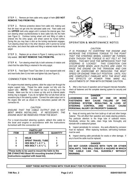
STEP 3. Replace pin as shown in Figure 3, making sure that it is<br />
fully seated. DO NOT REMOVE TAG FROM PIN.<br />
STEP 4. Turn steering wheel fully to both extremes of rotation and<br />
check that the cable fitting is retained in the entry spigot.<br />
STEP 5. Feed Spent Travel Tube (Item 2) over exposed cable end<br />
and insert bolts (Item 3) into helm and tighten fully (see Figure 2).<br />
CONNECTION TO ENGINE<br />
For engine-mounted steering systems, slide the output ram through the<br />
engine support tube. Thread the cable coupler nut fully onto the<br />
support tube. NOTE: The coupler nut has a locking ring in the<br />
threads. Make sure the nut is drawn up fully and its internal plastic<br />
locking ring is engaged. If you do not tighten this nut fully there will be<br />
excessive play in the steering system. Connect the cable output ram to<br />
the engine tiller arm as shown in the instructions packed with the<br />
connection kit.<br />
CAUTION<br />
ENSURE THAT THE CABLE OUTPUT END IS NOT<br />
BENT WHEN INSTALLING. IF NECESSARY, THE<br />
ENGINE MUST BE REMOVED FROM THE BOAT.<br />
For a boat-mounted steering system, attach the cable to<br />
the boat and engine in accordance with the instructions<br />
furnished with the connection kit.<br />
PARTS LIST<br />
ITEM DESCRIPTION QUANTITY<br />
1 HELM 1<br />
2 SPENT TRAVEL TUBE 1<br />
3 HEX BOLT ¼ X 1” L 2<br />
4 HEX BOLT ¼ X ¾” L 3*<br />
*These bolts to be used to mount the helm to the<br />
SB 27484/27483 Bezel Kit mounting bracket (Follow<br />
instructions supplied with bezel kit).<br />
CABLE<br />
FIGURE 2 3<br />
FIGURE 3<br />
OPERATION & MAINTENANCE NOTES<br />
CAUTION<br />
IT IS POSSIBLE TO OVERTRIM THE ENGINE AND<br />
INCREASE THE STEERING TORQUE TO THE POINT<br />
THAT THE STEERING WHEEL CANNOT BE TURNED,<br />
EVEN THOUGH THE TORQUE IS NOT FELT AT THE<br />
WHEEL. THIS MAY GIVE THE IMPRESSION THAT THE<br />
STEERING IS “LOCKED”. THIS CONDITION CAN<br />
OCCUR MORE WHEN JACK PLATES ARE USED TO<br />
RAISE THE ENGINE ON THE TRANSOM, AND CAN<br />
ONLY BE OVERCOME BY REDUCING THE BOAT<br />
SPEED OR ENGINE TRIM OUT POSITION. UNTIL YOU<br />
ARE COMPLETELY FAMILIAR WITH THE BOAT AND<br />
THE EFFECTS OF POWER TRIM, MAKE ALL<br />
ADJUSTMENTS OF TRIM WITH EXTREME CAUTION.<br />
1. After a few hours of operation and at frequent intervals thereafter,<br />
check all fasteners and the complete steering system for security and<br />
integrity.<br />
DANGER<br />
LOOSENING OR LOSS OF ONE OR MORE<br />
FASTENERS MAY CAUSE FAILURE OF THE<br />
STEERING SYSTEM, RESULTING IN LOSS OF<br />
STEERING CONTROL AND COULD CAUSE<br />
PERSONAL INJURY OR PROPERTY DAMAGE.<br />
2. Keep all moving parts free from build-up of salt and other foreign<br />
material. This will affect their operation and create steering problems.<br />
Pay particular attention to the hinge tube of outboard motors.<br />
Periodically remove the cable, clean hinge tube thoroughly and<br />
lubricate with a waterproof grease.<br />
3. Inspect periodically for corrosion. Any parts affected by corrosion<br />
must be replaced. When replacing hardware, self-locking hardware<br />
must be used.<br />
4. Inspect steering cable periodically for cracks or other damage. If<br />
any is found the cable must be replaced.<br />
DANGER<br />
DO NOT COVER CRACKS WITH TAPE OR OTHER<br />
SEALANTS, THIS WILL CREATE A HAZARD IN WHICH<br />
THE CABLE CAN FAIL SUDDENLY WITHOUT<br />
WARNING.<br />
KEEP THESE INSTRUCTIONS WITH YOUR BOAT FOR FUTURE REFERENCE.<br />
7/98 Rev. 2 Page 2 of 2 ISSH5150/5155<br />
2<br />
1


