

TELEFLEX NFB-SAFE-T-II Steering System Instruction - L-36 Fleet
TELEFLEX NFB-SAFE-T-II Steering System Instruction - L-36 Fleet
TELEFLEX NFB-SAFE-T-II Steering System Instruction - L-36 Fleet

You also want an ePaper? Increase the reach of your titles
YUMPU automatically turns print PDFs into web optimized ePapers that Google loves.
Marine<br />
Products<br />
These instructions show you how to install SSC62 steering cables into<br />
<strong>SAFE</strong>-T <strong>II</strong> <strong>NFB</strong> Helms. These helms contain a clutch mechanism<br />
to prevent the engine torque from being felt at the steering wheel. This<br />
reduces driver fatigue by eliminating constant fighting of the wheel. IT<br />
DOES NOT ELIMINATE THE ENGINE TORQUE. This can only be<br />
reduced by proper trim and tilt setting by trial and error when running<br />
the boat. The instructions for mounting the helm to the dash are given<br />
in the bezel kit instructions.<br />
For a complete <strong>SAFE</strong>-T <strong>II</strong> <strong>NFB</strong> steering system the following<br />
additional components are required:<br />
• Bezel Kit - SB27484 (90°) or SB27483 (20°)<br />
• <strong>Steering</strong> Cable - SSC62xx (xx = length in feet)<br />
• <strong>Steering</strong> Wheel - See Teleflex catalog.<br />
Note: Maximum wheel diameter is 16 inches.<br />
• Engine Connection Kit - See Teleflex catalog.<br />
Manufactured by<br />
Teleflex, Inc. USA<br />
640 North Lewis Road<br />
Limerick, PA 19468 (USA)<br />
(610) 495-7011<br />
®<br />
Copyright 1998, Teleflex Incorporated (USA)<br />
INSTALLER: THESE INSTRUCTIONS CONTAIN IMPORTANT <strong>SAFE</strong>TY INFORMATION AND MUST BE FORWARDED TO BOAT OWNER.<br />
WARNING<br />
BEFORE STARTING INSTALLATION READ THESE INSTRUCTIONS<br />
AND ENGINE MAKERS INSTRUCTIONS THOROUGHLY. FAILURE TO<br />
FOLLOW EITHER OF THESE INSTRUCTIONS OR INCORRECT<br />
ASSEMBLY CAN RESULT IN LOSS OF CONTROL AND CAUSE<br />
PROPERTY DAMAGE OR INJURY.<br />
DO NOT SUBSTITUTE PARTS FROM OTHER MANUFACTURERS,<br />
THEY MAY CAUSE A <strong>SAFE</strong>TY HAZARD FOR WHICH <strong>TELEFLEX</strong> INC.,<br />
USA CANNOT ACCEPT RESPONSIBILITY. USE <strong>TELEFLEX</strong> STEER-<br />
ING CABLES ONLY WITH THIS HELM.<br />
TO AVOID EXCESSIVE STEERING LOADS, AND TO GET THE BEST<br />
STEERING PERFORMANCE, THE OUTBOARD MOTOR OR OUTDRIVE<br />
TRIM TABS AND TILT POSITION MUST BE ADJUSTED AS<br />
INSTRUCTED IN THE MOTOR MANUFACTURERS OPERATION<br />
MANUAL. FAILURE TO DO SO CAN EFFECT THE PERFORMANCE<br />
OF THE BOAT AND ITS <strong>SAFE</strong> OPERATION.<br />
DO NOT ATTACH ANY ELECTRICAL GROUND WIRES TO THE HELM.<br />
THIS WOULD RESULT IN AN ELECTROLYTIC REACTION TO THE<br />
STEERING CABLE THAT MAY RESULT IN CABLE FAILURE OR<br />
GREATLY REDUCED SERVICE LIFE.<br />
WARNING<br />
HELMS MUST NOT BE DISASSEMBLED FOR ANY<br />
REASON. FAILURE TO REASSEMBLE CORRECTLY<br />
MAY LEAD TO TOTAL FAILURE OF THE SYSTEM,<br />
WHICH COULD RESULT IN PERSONAL INJURY OR<br />
PROPERTY DAMAGE.<br />
NOTE: HELMS AND CABLE ASSEMBLIES ARE SUPPLIED<br />
LUBRICATED READY FOR INSTALLATION, DO NOT ADD ANY<br />
LUBRICANT TO EITHER ASSEMBLY. USE OF OTHER<br />
LUBRICANTS CAN CAUSE DAMAGE TO THE STEERING CABLE,<br />
RESULTING IN THE CABLE SEIZING OR PREMATURE WEAR.<br />
KEEP THE CABLE AND DRIVE ASSEMBLY CLEAN DURING<br />
INSTALLATION. DIRT WILL DAMAGE THE SYSTEM AND CAUSE<br />
PREMATURE WEAR. DO NOT TAKE THE PLASTIC SLEEVE OFF<br />
THE END OF THE CABLE UNTIL YOU ARE READY TO INSTALL IT<br />
INTO THE HELM.<br />
PREPARATION FOR INSTALLATION<br />
Before the steering cable can be installed, the helm, bezel, and<br />
steering wheel must be fully installed as shown in the bezel kit<br />
instructions.<br />
CABLE ROUTING<br />
The steering cable must be routed to the starboard side of the boat.<br />
When routing the steering cable, select a path with the minimum<br />
number of bends, making the bends as large a radius as possible. DO<br />
NOT MAKE BENDS OF LESS THAN 8” RADIUS. Sharp or frequent<br />
bends will result in hard steering and premature cable wear. When it is<br />
necessary to pass through a bulkhead, a 1-1/2” diameter hole is<br />
required. Cable should be clamped or tied for support at regular<br />
intervals.<br />
CAUTION<br />
THE CABLE MUST NOT BE BUNDLED TOGETHER<br />
WITH ELECTRICAL WIRING. THE CABLE MUST NOT<br />
REST ON SHARP EDGES WHICH CAN CAUSE<br />
CHAFING.<br />
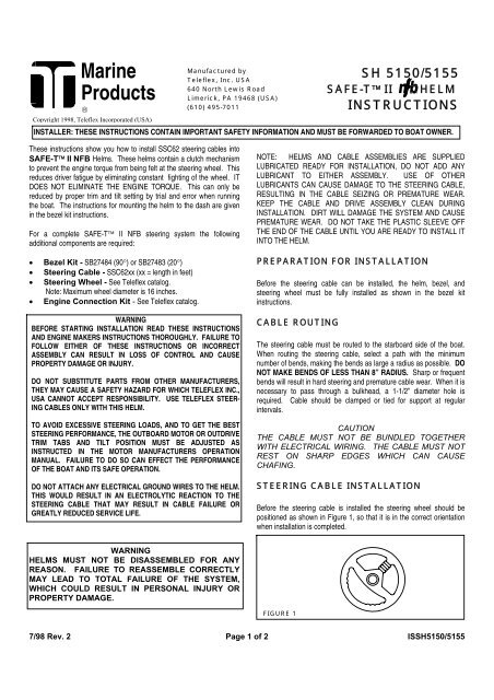
STEERING CABLE INSTALLATION<br />
Before the steering cable is installed the steering wheel should be<br />
positioned as shown in Figure 1, so that it is in the correct orientation<br />
when installation is completed.<br />
FIGURE 1<br />
SH 5150/5155<br />
<strong>SAFE</strong>-T <strong>II</strong> HELM<br />
INSTRUCTIONS<br />
7/98 Rev. 2 Page 1 of 2 ISSH5150/5155
STEP 1. Remove pin from cable entry spigot of helm (DO NOT<br />
REMOVE TAG FROM PIN).<br />
STEP 2. Remove protective sleeve from cable end, making sure<br />
that dirt does not get onto the lubricated cable end. Feed cable end<br />
into UPPER helm entry spigot until it contacts the internal gear, then<br />
turn steering wheel counterclockwise to draw cable fully into the helm<br />
(see Figure 2). Continue turning wheel until end fitting of cable is<br />
entered into the entry spigot, and wheel cannot be turned further.<br />
During this you may hear a click as the locking mechanism engages.<br />
Turn steering wheel fully in the other direction until it cannot be turned<br />
any further, and check that cable end fitting is retained inside the entry<br />
spigot.<br />
STEP 3. Replace pin as shown in Figure 3, making sure that it is<br />
fully seated. DO NOT REMOVE TAG FROM PIN.<br />
STEP 4. Turn steering wheel fully to both extremes of rotation and<br />
check that the cable fitting is retained in the entry spigot.<br />
STEP 5. Feed Spent Travel Tube (Item 2) over exposed cable end<br />
and insert bolts (Item 3) into helm and tighten fully (see Figure 2).<br />
CONNECTION TO ENGINE<br />
For engine-mounted steering systems, slide the output ram through the<br />
engine support tube. Thread the cable coupler nut fully onto the<br />
support tube. NOTE: The coupler nut has a locking ring in the<br />
threads. Make sure the nut is drawn up fully and its internal plastic<br />
locking ring is engaged. If you do not tighten this nut fully there will be<br />
excessive play in the steering system. Connect the cable output ram to<br />
the engine tiller arm as shown in the instructions packed with the<br />
connection kit.<br />
CAUTION<br />
ENSURE THAT THE CABLE OUTPUT END IS NOT<br />
BENT WHEN INSTALLING. IF NECESSARY, THE<br />
ENGINE MUST BE REMOVED FROM THE BOAT.<br />
For a boat-mounted steering system, attach the cable to<br />
the boat and engine in accordance with the instructions<br />
furnished with the connection kit.<br />
PARTS LIST<br />
ITEM DESCRIPTION QUANTITY<br />
1 HELM 1<br />
2 SPENT TRAVEL TUBE 1<br />
3 HEX BOLT ¼ X 1” L 2<br />
4 HEX BOLT ¼ X ¾” L 3*<br />
*These bolts to be used to mount the helm to the<br />
SB 27484/27483 Bezel Kit mounting bracket (Follow<br />
instructions supplied with bezel kit).<br />
CABLE<br />
FIGURE 2 3<br />
FIGURE 3<br />
OPERATION & MAINTENANCE NOTES<br />
CAUTION<br />
IT IS POSSIBLE TO OVERTRIM THE ENGINE AND<br />
INCREASE THE STEERING TORQUE TO THE POINT<br />
THAT THE STEERING WHEEL CANNOT BE TURNED,<br />
EVEN THOUGH THE TORQUE IS NOT FELT AT THE<br />
WHEEL. THIS MAY GIVE THE IMPRESSION THAT THE<br />
STEERING IS “LOCKED”. THIS CONDITION CAN<br />
OCCUR MORE WHEN JACK PLATES ARE USED TO<br />
RAISE THE ENGINE ON THE TRANSOM, AND CAN<br />
ONLY BE OVERCOME BY REDUCING THE BOAT<br />
SPEED OR ENGINE TRIM OUT POSITION. UNTIL YOU<br />
ARE COMPLETELY FAMILIAR WITH THE BOAT AND<br />
THE EFFECTS OF POWER TRIM, MAKE ALL<br />
ADJUSTMENTS OF TRIM WITH EXTREME CAUTION.<br />
1. After a few hours of operation and at frequent intervals thereafter,<br />
check all fasteners and the complete steering system for security and<br />
integrity.<br />
DANGER<br />
LOOSENING OR LOSS OF ONE OR MORE<br />
FASTENERS MAY CAUSE FAILURE OF THE<br />
STEERING SYSTEM, RESULTING IN LOSS OF<br />
STEERING CONTROL AND COULD CAUSE<br />
PERSONAL INJURY OR PROPERTY DAMAGE.<br />
2. Keep all moving parts free from build-up of salt and other foreign<br />
material. This will affect their operation and create steering problems.<br />
Pay particular attention to the hinge tube of outboard motors.<br />
Periodically remove the cable, clean hinge tube thoroughly and<br />
lubricate with a waterproof grease.<br />
3. Inspect periodically for corrosion. Any parts affected by corrosion<br />
must be replaced. When replacing hardware, self-locking hardware<br />
must be used.<br />
4. Inspect steering cable periodically for cracks or other damage. If<br />
any is found the cable must be replaced.<br />
DANGER<br />
DO NOT COVER CRACKS WITH TAPE OR OTHER<br />
SEALANTS, THIS WILL CREATE A HAZARD IN WHICH<br />
THE CABLE CAN FAIL SUDDENLY WITHOUT<br />
WARNING.<br />
KEEP THESE INSTRUCTIONS WITH YOUR BOAT FOR FUTURE REFERENCE.<br />
7/98 Rev. 2 Page 2 of 2 ISSH5150/5155<br />
2<br />
1


