Host Interface Modules - bei ID-Systems
Host Interface Modules - bei ID-Systems
Host Interface Modules - bei ID-Systems

You also want an ePaper? Increase the reach of your titles
YUMPU automatically turns print PDFs into web optimized ePapers that Google loves.
HOST INTERFACE MODULES<br />
INSTRUCTION MANUAL<br />
Profibus DeviceNet Ethernet/IP<br />
Modbus TCP<br />
CANopen Profinet CC-Link<br />
DESCRIPTION<br />
Ethernet TCP/IP<br />
Figure 1 – General View<br />
The <strong>Host</strong> <strong>Interface</strong> <strong>Modules</strong> are accessories for the CBX500 connection<br />
boxes. They provide Stand Alone or Master Scanner connection to a<br />
network. The following types are available:<br />
BM200 Ethernet TCP/IP Module 93ACC1851<br />
BM210 Ethernet TCP/IP IP65 Module 93ACC1852<br />
BM300 Profibus Module 93ACC1810<br />
BM310 Profibus IP65 Module 93ACC1811<br />
BM400 DeviceNet IP65 Module 93ACC1814<br />
BM500 Ethernet/IP Module 93ACC1812<br />
BM510 Ethernet/IP IP65 Module 93ACC1813<br />
BM520 Ethernet/IP IP54 Module 93ACC1840<br />
BM600 CANopen Module 93ACC1815<br />
BM700 Profinet Module 93ACC1816<br />
BM1100 CC-Link Module 93ACC1845<br />
BM1200 Modbus TCP Module 93ACC1848<br />
BM1210 Modbus TCP IP65 Module 93ACC1849<br />
NOTE<br />
These accessories are managed by the reading device<br />
application software. See the Accessories paragraph in<br />
your reading device Reference Manual for the list of<br />
supported CBX Series accessories.<br />
Technical Features<br />
Operating Temperature 0° to 50 °C (+32° to 122 °F)<br />
Storage Temperature -20° to 70 °C (-4° to 158 °F)<br />
Humidity max. 90% non condensing<br />
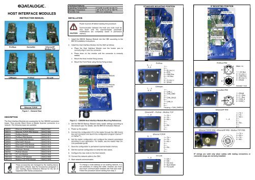
INSTALLATION<br />
CAUTION<br />
Power must be off before starting this procedure.<br />
Communication between the <strong>Host</strong> and node must be<br />
shut down until the scanner/reader parameter<br />
modifications are completely saved in permanent<br />
memory.<br />
1. Install the BM100 Backup Module into the CBX according to the<br />
BM100 Installation Instructions.<br />
2. Install the <strong>Host</strong> <strong>Interface</strong> Module into the CBX as follows:<br />
a. Place the <strong>Host</strong> <strong>Interface</strong> Module over the locator pins to<br />
correctly align it over the connector.<br />
b. Press down on the module until the connector is correctly<br />
seated.<br />
c. Mount the three module fixing screws.<br />
d. Mount the Front Panel using the two fixing screws.<br />
Figure 2 – CBX500 <strong>Host</strong> <strong>Interface</strong> Module Mounting References<br />
3. Set the BM100 Backup Module rotary switch settings according to<br />
the network type. For details, see the BM100 Instruction Manual.<br />
4. Power up the system.<br />
5. Connect the configuration PC to the reader through the CBX (9-pin)<br />
Aux port connector and launch the configuration program (Genius<br />
or VisiSet).<br />
6. Get the reader configuration and configure the network parameters<br />
according to your application. For details, see the reader Help On-<br />
Line parameter guide.<br />
7. Save the configuration to permanent scanner/reader memory.<br />
8. Get the scanner configuration to verify the new values.<br />
9. Configure the new node on the <strong>Host</strong> network.<br />
10. Connect the network cable to the CBX.<br />
11. Start network communication.<br />
NOTE<br />
<strong>Host</strong> <strong>Interface</strong> Module<br />
IPxx Connector<br />
<strong>Host</strong> <strong>Interface</strong> Module<br />
Standard Connector<br />
Module Locator Pins<br />
To change a node address on an existing network, it is<br />
not necessary to unplug the cable, however you must<br />
shut down communication between the <strong>Host</strong> and node.<br />
Follow the procedure above starting from step 3.<br />
STANDARD MOUNTING POSITION<br />
Module Locator Pins<br />
5......1<br />
9...6<br />
1......5<br />
6...9<br />
Profibus<br />
CANopen<br />
1 = -<br />
2 = -<br />
3 = B Line (+)<br />
4 = RTS<br />
5 = GND Bus<br />
6 = +5V Bus<br />
7 = -<br />
8 = A Line (-)<br />
9 = Shield<br />
1 = -<br />
2 = CAN_L<br />
3 = CAN_GND<br />
4 = -<br />
5 = CAN_SHLD<br />
6 = -<br />
7 = CAN_H<br />
8 = -<br />
9 = -<br />
Housing = CAN_SHIELD<br />
Ethernet/IP – Profinet - /Modbus TCP<br />
1....8<br />
1 = TX +<br />
2 = TX -<br />
3 = RX +<br />
4 = -<br />
5 = -<br />
6 = RX -<br />
7 = -<br />
8 = -<br />
8....1<br />
1....5<br />
Fixing Screws<br />
Ethernet TCP/IP<br />
CC-Link<br />
Fixing Screw<br />
1 = TX +<br />
2 = TX -<br />
3 = RX +<br />
4 = -<br />
5 = -<br />
6 = RX -<br />
7 = -<br />
8 = -<br />
1 = DA +<br />
2 = DB -<br />
3 = DG Gnd<br />
4 = SLD Shield<br />
5 = FG Earth<br />
IP MOUNTING POSITION<br />
Fixing Screws<br />
Fixing Screw<br />
Module Locator Pins<br />
Profibus IP65<br />
5<br />
5<br />
2<br />
3<br />
1<br />
4<br />
DeviceNet IP65<br />
5<br />
2<br />
3<br />
Ethernet/IP IP54<br />
1....8<br />
1<br />
4<br />
2<br />
3<br />
1<br />
4<br />
Male = In<br />
1 = +5V Bus<br />
2 = A Line (-)<br />
3 = GND Bus<br />
4 = B Line (+)<br />
5 = Shield<br />
Female = Out<br />
1 = Shield<br />
2 = V + Bus<br />
3 = V - Bus<br />
4 = CAN_H<br />
5 = CAN_L<br />
1 = TX +<br />
2 = TX -<br />
3 = RX +<br />
4 = -<br />
5 = -<br />
6 = RX -<br />
7 = -<br />
8 = -<br />
Ethernet TCP/IP IP65 - Ethernet/IP IP65 - Modbus TCP IP65<br />
1<br />
4 2<br />
3<br />
1 = TX +<br />
2 = RX +<br />
3 = TX -<br />
4 = RX -<br />
IP ratings are valid only when cables with mating connectors or<br />
connector plugs are correctly installed.
Profibus IP65 Installation<br />
Figure 3 –<br />
Bus Termination Switches<br />
Profibus Module IP65 Mounting<br />
Bus termination switches are located on the back of the connector panel<br />
for the Profibus IP65 connection.<br />
ONLY the last slave node on the Profibus network must be terminated<br />
and this can be done in one of two ways:<br />
� Connect a standard Profibus terminator onto the M12 Female<br />
connector, (i.e. Lumberg "SAC-5P-M12MS PB TR" terminator).<br />
In this case ALL the bus termination switches must be OFF.<br />
� If no standard Profibus terminator is used, set ALL the bus<br />
termination switches to ON. In this case install a connector plug onto<br />
the M12 Female connector to maintain the IP rating.<br />
ALL Profibus slave nodes other than the last one, must have ALL<br />
the switches set to OFF.<br />
821001423 (Rev. D)<br />
DeviceNet IP65 Installation<br />
Figure 4 –<br />
DeviceNet Module<br />
IP65 Mounting<br />
Ethernet/IP IP65 -<br />
Modbus TCP IP65 Installation<br />
Figure 5 –<br />
Ethernet/IP Module –<br />
Modbus TCP Module<br />
IP65 Mounting<br />
Ethernet TCP/IP IP65 Installation<br />
Figure 6 –<br />
Ethernet TCP/IP Module –<br />
IP65 Mounting<br />
Ethernet/IP IP54 Installation<br />
Figure 7 –<br />
Ethernet/IP Module<br />
IP54 Mounting<br />
LED INDICATORS<br />
1 2<br />
Profibus<br />
1 = Operation Mode LED<br />
Off Not on-line, No power<br />
Green On-line, data exchange<br />
Flashing Green On-line, clear<br />
Flashing Red (1 flash) Parameterization error<br />
Flashing Red (2 flashes) Profibus configuration error<br />
2 = Status LED<br />
Off No power or not initialized<br />
Green Initialized<br />
Flashing Green Initialized, diagnostic event(s) present<br />
Red Exception error<br />
DeviceNet<br />
1 = Network Status LED<br />
Off Not on-line, No power<br />
Green On-line, one or more connections<br />
established<br />
Flashing Green (1 Hz) On-line, no connections established<br />
Red Critical link failure<br />
Flashing Red (1 Hz) One or more connections timed-out<br />
Alternating Red/Green Self test<br />
2 = Module Status LED<br />
Off No power<br />
Green Operating in normal condition<br />
Flashing Green (1 Hz) Missing or incomplete configuration,<br />
device needs commissioning<br />
Red Unrecoverable fault(s)<br />
Flashing Red (1 Hz) Recoverable fault(s)<br />
Alternating Red/Green Self test<br />
Ethernet/IP<br />
1 = Network Status LED<br />
Off No power or no IP address<br />
Green On-line, one or more connections<br />
established (CIP Class 1 or 3)<br />
Flashing Green On-line, no connections established<br />
Red Duplicate IP address, Fatal error<br />
Flashing Red One or more connections timed-out<br />
(CIP Class 1 or 3)<br />
2 = Module Status LED<br />
Off No power<br />
Green Controlled by a Fieldbus Master in Run<br />
state<br />
Flashing Green Not configured or Fieldbus Master in Idle<br />
state<br />
Red Major fault (Exception state, Fatal error,<br />
etc.)<br />
Flashing Red Recoverable fault(s)<br />
CANopen<br />
1 = Run LED<br />
Off No power<br />
Green In Operational state<br />
Blinking Green In Pre-operational state<br />
Flashing Green (1 flash) In Stopped state<br />
Flickering Green Autobaud<br />
Red In Exception state, Fatal event<br />
2 = Error LED<br />
Off No power<br />
Flashing Red (1 flash) Bus error counter warning limit reached<br />
Flickering Red LSS services are in progress<br />
Flashing Red (2 flashes) Error control event<br />
Red Bus off, Fatal event<br />
Profinet<br />
1 = Network Status LED<br />
Off No power, No connection with IO<br />
controller<br />
Green Connection with IO controller<br />
established, IO controller in Run state<br />
Red Connection with IO controller<br />
established, IO controller in Stop state<br />
2 = Module Status LED<br />
Off No power or Not Initialized<br />
Green Normal operation<br />
Flashing Green (1 flash) Diagnostic event(s)<br />
Flashing Green (2 flashes) Blink (node identification)<br />
Red Exception error<br />
Flashing Red (1 flash) Configuration error<br />
Flashing Red (2 flashes) IP address not set<br />
Flashing Red (3 flashes) Station Name not set<br />
Flashing Red (4 flashes) Internal error<br />
CC-Link<br />
1 = Run LED<br />
Off No power, No network participation,<br />
Timeout status<br />
Green Participating, normal operation<br />
Red Major fault, Fatal error<br />
2 = Error LED<br />
Off No power or no error detected<br />
Red Major fault, (Exception or Fatal event)<br />
Flickering Red CRC error (temporary flickering)<br />
Flashing Red Station Number or Baud rate has<br />
changed since startup<br />
Modbus TCP<br />
1 = Network Status LED<br />
Off No power or no IP address<br />
Green Module is in Process Active or Idle state<br />
Flashing Green Waiting for connections<br />
Red Duplicate IP address, or Fatal event<br />
Flashing Red Process Active Timeout<br />
2 = Module Status LED<br />
Off No power<br />
Green Normal operation<br />
Red Major fault (Exception state, Fatal error,<br />
etc.)<br />
Flashing Red Minor fault<br />
Ethernet TCP/IP<br />
Network Link Status LED<br />
Yellow<br />
Network Activity Status LED<br />
Green<br />
Network Link Status LED<br />
Off No link has been detected<br />
Yellow Network link has been detected<br />
Network Activity Status LED<br />
Off No network activity<br />
Flashing Green Network data is transmitted or received