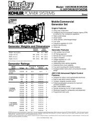
GL6000-AUS GL7000-USA - Hardy Diesel Generators
GL6000-AUS GL7000-USA - Hardy Diesel Generators
GL6000-AUS GL7000-USA - Hardy Diesel Generators

You also want an ePaper? Increase the reach of your titles
YUMPU automatically turns print PDFs into web optimized ePapers that Google loves.
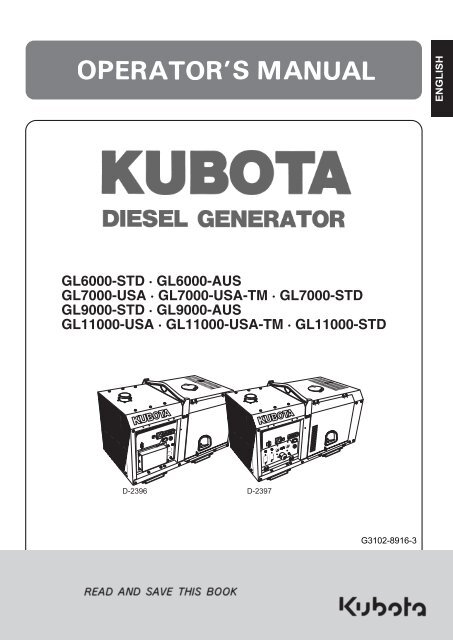
<strong>GL6000</strong>-STD · <strong>GL6000</strong>-<strong>AUS</strong><br />
<strong>GL7000</strong>-<strong>USA</strong> · <strong>GL7000</strong>-<strong>USA</strong>-TM · <strong>GL7000</strong>-STD<br />
GL9000-STD · GL9000-<strong>AUS</strong><br />
GL11000-<strong>USA</strong> · GL11000-<strong>USA</strong>-TM · GL11000-STD<br />
D-2396 D-2397
ENGLISH<br />
3 WARNING<br />
To prevent electrical shock the following instruction must be followed.<br />
Before the generator can be connected to a building’s electrical<br />
system, a licensed electrician must install an isolation (transfer) switch<br />
in the building’s main fuse box. The switch is the connection point for<br />
generator power and allows selection of generator or main line power<br />
to the building.<br />
This will prevent the generator from charging the main power line<br />
(backfeeding) when the main power supply has failed or has been<br />
turned off for line repair. Backfeeding can electrocute or injure line<br />
maintenance personnel. Also, generator and building electrical system<br />
damage can occur when normal operating power returns if unit is used<br />
without an isolation switch.<br />
California Proposition 65<br />
WARNING<br />
Engine exhaust, some of its constituents,<br />
certain vehicle components and fluids,<br />
contain or emit chemicals known to the<br />
State of California to cause cancer and birth<br />
defects or other reproductive harm.<br />
IMPORTANT<br />
The engine in this machine is not equipped by the manufacture with<br />
a standard spark arrester.<br />
It is a violation of California Public Resource Code Section 4442 to<br />
use or operate this engine on or near any forest-covered, brushcovered<br />
land, or grass- covered land unless the exhaust system is<br />
equipped with a working spark arrester meeting state laws. Other<br />
states or federal areas may have similar laws.
3DANGER :<br />
FOREWORD<br />
You are now the proud owner of a KUBOTA <strong>Diesel</strong> Engine Generator. This<br />
generator is a product of KUBOTA quality engineering and manufacturing. It<br />
is made of fine materials and under a rigid quality control system with<br />
correct maintenance. It will give you long, satisfactory service. To obtain the<br />
best use of your generator, please read this manual carefully. It will help you<br />
become familiar with the operation of the generator and contains many<br />
helpful hints about generator maintenance. It is KUBOTA's policy to utilize as<br />
quickly as possible every advance in our research. The immediate use of<br />
new techniques in the manufacture of products may cause some small parts<br />
of this manual to be outdated. KUBOTA distributors and dealers will have the<br />
most up-to-date information. Please do not hesitate to consult with them.<br />
3WARNING : Indicates a potentially hazardous situation which, if not<br />
avoided, could result in death or serious injury.<br />
3CAUTION :<br />
IMPORTANT :<br />
NOTE :<br />
3 SAFETY FIRST<br />
This symbol, the industry's "Safety Alert Symbol", is used throughout this<br />
manual and on labels on the machine itself to warn of the possibility of<br />
personal injury. Read these instructions carefully. It is essential that you<br />
read the instructions and safety regulations before you attempt to assemble<br />
or use this unit.<br />
Indicates an imminently hazardous situation which, if<br />
not avoided, will result in death or serious injury.<br />
Indicates a potentially hazardous situation which, if not<br />
avoided, may result in minor or moderate injury.<br />
Indicates that equipment or property damage could<br />
result if instructions are not followed.<br />
Gives helpful information.
ENGLISH<br />
CONTENTS<br />
SAFETY PRECAUTIONS ..................................................................................... 1<br />
SERVICING OF GENERATOR ................................................................................. 1<br />
SPECIFICATION ....................................................................................................... 2<br />
NOMENCLATURE..................................................................................................... 4<br />
GROUND FAULT CIRCUIT INTERRUPTER (GFCI) RECEPTACLE ....................... 8<br />
PREPARATION TO SUPPLY THE ELECTRIC POWER ........................................ 10<br />
CONNECTING THE LOAD...................................................................................... 12<br />
PRE-OPERATION CHECK...................................................................................... 16<br />
OPERATING THE GENERATOR............................................................................ 19<br />
SERVICE INTERVALS ............................................................................................ 23<br />
PERIODIC SERVICE............................................................................................... 25<br />
TRANSPORTING / STORAGE................................................................................ 37<br />
TROUBLESHOOTING............................................................................................. 38<br />
AUTOMATIC START/STOP UNIT (A S/S UNIT)..................................................... 40<br />
WIRING DIAGRAM.................................................................................................. 41
SAFETY PRECAUTIONS<br />
SAFETY PRECAUTIONS<br />
A To operate the machine safely, be sure to follow the instructions below.<br />
DANGER<br />
To avoid personal injury:<br />
A Hazard of being caught up in the machine: Do<br />
not touch any rotating parts.<br />
A Do not use or charge the battery if its fluid level<br />
stands below the LOWER mark.<br />
Otherwise, the component parts may deteriorate<br />
earlier than expected, which may shorten the<br />
service life or cause an explosion. Immediately,<br />
add distilled water until the fluid level is between<br />
the UPPER and LOWER levels. (for only refillable<br />
battery)<br />
WARNING<br />
To avoid personal injury:<br />
A Exhaust gas poisoning hazard: Do not use the<br />
machine in any poorly-ventilated place such as<br />
indoors and tunnels.<br />
A Exhaust gas poisoning and fire hazard: Do not<br />
direct the exhaust to people and buildings.<br />
A Electric shock hazard: Do not touch the machine<br />
with wet hands.<br />
A Electric shock hazard: Do not touch the<br />
terminals and sockets while the machine is<br />
running.<br />
A Electric shock and injury hazard: Do not check<br />
and service the machine while it is running.<br />
A Electric shock and injury hazard: Do not tamper<br />
with the machine.<br />
A Fire hazard: Flames prohibited. Keep the<br />
machine more than 1 m(3 feet) away from<br />
flammable materials.<br />
A Electric shock hazard: Do not use the machine in<br />
the rain.<br />
1<br />
ENGLISH
ENGLISH<br />
2 SAFETY PRECAUTIONS<br />
CAUTION<br />
To avoid personal injury:<br />
A Electric shock and fire hazard: Do not connect<br />
the machine to any indoor (commercial) power<br />
outlet.<br />
A Electric shock and injury hazard: Do not allow<br />
children to run the machine.<br />
A Electric shock and injury hazard: Turn off the<br />
circuit breaker before starting the machine.<br />
A Injury hazard: Do not touch the muffler.<br />
A Injury hazard: Do not run the machine tilted.<br />
A Injury hazard: Do not move the machine while it<br />
is running.<br />
A Fire hazard: Stop the engine before adding fuel.<br />
A Fire hazard: Do not enclose the machine, nor<br />
cover it with a box or the like.<br />
A Fire hazard: Pay attention to the type and<br />
amount of fuel.<br />
A Do not get the warning label dirty or peeled off.<br />
A Be sure to hand over the operation manual to<br />
any other operator.<br />
A Electric shock hazard: Ground the machine<br />
using the ground terminal on the control panel.
CAUTION<br />
To avoid personal injury:<br />
A Anti-freeze contains poison. Wear rubber gloves<br />
to avoid personal injury. In case of contact with<br />
skin, wash it off immediately.<br />
A DO NOT mix different types of Anti-freeze. The<br />
mixture can produce chemical reaction causing<br />
harmful substances. Use approved Anti-freeze.<br />
A Be mindful of the environment and the ecology.<br />
Before draining any fluids, find out the correct<br />
way of disposing of them. Observe the relevant<br />
environmental protection regulations when<br />
disposing of oil, fuel, coolant, brake fluid, filters<br />
and batteries.<br />
A When draining fluids from the engine, place<br />
some container underneath the engine body.<br />
A DO NOT pour waste onto the grounds, down a<br />
drain, or into any water source.<br />
SAFETY PRECAUTIONS<br />
3<br />
ENGLISH
ENGLISH<br />
4 SAFETY PRECAUTIONS<br />
CAUTION<br />
To avoid personal injury:<br />
A When checking engine or servicing, place the<br />
engine on a wide and level ground. DO NOT work<br />
on anything that is supported ONLY by lift jacks<br />
or a hoist. Always use blocks or correct stands<br />
to support the engine before servicing.<br />
A Detach the battery from the engine before<br />
conducting service. Put a "DO NOT OPERATE!"<br />
tag in the key switch to avoid accidental starting.<br />
A To avoid sparks from an accidental short circuit<br />
always disconnect the battery's ground cable (-)<br />
first and connect it last.<br />
A Be sure to stop the engine and remove the key<br />
when conducting daily and periodic<br />
maintenance, servicing and cleaning.<br />
A Check or conduct maintenance after the engine,<br />
coolant, muffler, or muffler cover have been<br />
cooled off completely.<br />
A Always use the appropriate tools and jig-fixture<br />
in good condition when performing any service<br />
work. Make sure you understand how to use<br />
them before service.<br />
A Use ONLY correct engine barring techniques for<br />
manually rotating the engine. DO NOT attempt to<br />
rotate the engine by pulling or prying on the<br />
cooling fan and V-belt. This practice can cause<br />
serious personal injury or premature machine<br />
damage to the cooling fan.<br />
A Replace fuel pipes and lubricant pipes with their<br />
hose clamps every 2 years or earlier whether<br />
they are damaged or not. They are made of<br />
rubber and are aged gradually.<br />
A When servicing is performed together by two or<br />
more persons, take care to perform all work<br />
safely.<br />
A Keep first aid kit and fire extinguisher handy at<br />
all times.
SAFETY PRECAUTIONS<br />
DANGER, WARNING AND CAUTION LABELS<br />
Pay special attention to all labels on the generator.<br />
Refer to following representations for labels used on the GL Series Generator. Labels are available<br />
individually from your KUBOTA Dealer.<br />
(1) Part No. G3907-8832-0 (2) Part No. G3907-8830-0<br />
(3) Part No. G3907-8836-0 (4) Part No. G3907-8831-0<br />
(5) Part No. G3102-5090-2 (for <strong>USA</strong>)<br />
(5) Part No. 18901-5090-2<br />
(6) Part No. G3907-8824-0<br />
5<br />
ENGLISH
ENGLISH<br />
6 SAFETY PRECAUTIONS<br />
(7) Part No. 18620-8806-0 (8) Part No. G3907-8833-0<br />
(9) Part No. G3102-8841-0 (10) Part No. G3101-8832-0<br />
(11) Part No. 6C040-5559-0 (12) Part No. G3102-8806-0<br />
(13) Part No. G3906-8831-0 (14) Part No. G3102-8838-0 (for U.S.A.)<br />
(15) Part No. G3102-8839-0 (for U.S.A.)
SAFETY PRECAUTIONS<br />
CARE OF DANGER, WARNING AND CAUTION LABELS<br />
1. Keep danger, warning and caution labels clean and free from obstructing material.<br />
2. Clean danger, warning and caution labels with soap and water, dry with a soft cloth.<br />
3. Replace damaged or missing danger, warning and caution labels with new labels from your<br />
local KUBOTA Dealer.<br />
4. If a component with danger, warning and caution label(s) affixed is replaced with new part,<br />
make sure new label(s) is (are) attached in the same location(s) as the replaced component.<br />
5. Mount new danger, warning and caution labels by applying on a clean dry surface and<br />
pressing any bubbles to outside edge.<br />
7<br />
ENGLISH
SERVICING OF GENERATOR<br />
Your dealer is interested in your new generator and has<br />
the desire to help you get the most value from it. After<br />
reading this manual thoroughly, you will find that you<br />
can do some of the regular maintenance yourself.<br />
However, when in need of parts or major service, be<br />
sure to see your KUBOTA Dealer.<br />
For service, contact the KUBOTA Dealership from<br />
which you purchased your generator or your local<br />
KUBOTA Dealer.<br />
When in need of parts, be prepared to give your dealer<br />
the generator and engine serial numbers.<br />
Locate the serial numbers now and record them in the<br />
space provided below.<br />
model Serial No.<br />
Generator<br />
Engine<br />
Date of<br />
Purchase<br />
Name of Dealer<br />
(To be filled in by purchaser)<br />
(1) Generator serial number<br />
(2) Generator model<br />
(3) Engine serial number<br />
SERVICING OF GENERATOR<br />
1<br />
ENGLISH
ENGLISH<br />
2 SPECIFICATION<br />
SPECIFICATION<br />
GENERATOR<br />
Model Unit<br />
–STD<br />
<strong>GL6000</strong><br />
–<strong>AUS</strong> –<strong>USA</strong><br />
<strong>GL7000</strong><br />
–<strong>USA</strong>-TM –STD<br />
Design — Salient-pole, revolving-field AC generator (AVR system with separate and self-excitation brush)<br />
Frequency Hz 50 60<br />
Rated Output (COP)<br />
kVA<br />
kW<br />
5.5<br />
5.5<br />
6.5<br />
6.5<br />
Rated Voltage V 220 240 120/240 110/220<br />
Rated amperage A 25 22.9 54.2/27.1 59.1/29.5<br />
Phase & Wire ø-W 1-2 1-4<br />
Power Factor % 100<br />
No. of Poles — 2<br />
Insulation — Rotor coil: Class F, Stator coil: Class B<br />
Voltage Regulation % 5 (No load to full load)<br />
Type of Coupling<br />
DIESEL ENGINE<br />
— Direct coupled<br />
Model — Z482<br />
Design — Vertical, water-cooled, 4-cycle diesel engine<br />
No. of cylinders — 2<br />
Bore × stroke mm (in.) ø 67 × 68 (2.6 × 2.7)<br />
Displacement L (cu. in.) 0.479 (29.2)<br />
Engine speed rpm 3000 3600<br />
Lubricating Oil — API service class CD or higher<br />
Oil capacity L (U.S.gal.) 2.2 (0.58)<br />
Coolant capacity<br />
SET<br />
L (U.S.gal.) 3.7 (0.98)<br />
Fuel — <strong>Diesel</strong> fuel No. 2 (ASTM D975)<br />
Fuel consumption (at full load) L (U.S.gal.)/h 2.4 (0.63) 2.7 (0.71)<br />
Fuel tank capacity L (U.S.gal.) 28 (7.4)<br />
Continuous Operating Hours hrs 12 10<br />
Battery (V × Ah/5Hr) — 38B20R (12V × 28Ah)<br />
Starting System — Electric<br />
L × W × H mm (in.) 1066 × 618 × 698 (42.0 × 24.3 × 27.5)<br />
Approx Net Wt. kg (lbs.) 235 (518)<br />
Output<br />
Terminal<br />
Receptacle<br />
—<br />
—<br />
<br />
<br />
—<br />
<br />
—<br />
<br />
<br />
<br />
<br />
<br />
Emergency Stop System — In case of abnormal : Oil pressure, water temperature
GENERATOR<br />
SPECIFICATION<br />
Model Unit<br />
–STD<br />
GL9000<br />
–<strong>AUS</strong> –<strong>USA</strong><br />
GL11000<br />
–<strong>USA</strong>-TM –STD<br />
Design — Salient-pole, revolving-field AC generator (AVR system with separate and self-excitation brush)<br />
Frequency Hz 50 60<br />
Rated Output (COP)<br />
kVA<br />
kW<br />
8<br />
8<br />
10<br />
10<br />
Rated Voltage V 220 240 120/240 110/220<br />
Rated amperage A 36.4 33.3 83.3/41.7 90.9/45.5<br />
Phase & Wire ø-W 1-2 1-3<br />
Power Factor % 100<br />
No. of Poles — 2<br />
Insulation — Rotor coil: Class F, Stator coil: Class B<br />
Voltage Regulation % 5 (No load to full load)<br />
Type of Coupling<br />
DIESEL ENGINE<br />
— Direct coupled<br />
Model — D722<br />
Design — Vertical, water-cooled, 4-cycle diesel engine<br />
No. of cylinders — 3<br />
Bore × stroke mm (in.) ø 67 × 68 (2.6 × 2.7)<br />
Displacement L (cu. in.) 0.719 (43.9)<br />
Engine speed rpm 3000 3600<br />
Lubricating Oil — API service class CD or higher<br />
Oil capacity L (U.S.gal.) 3.4 (0.90)<br />
Coolant capacity<br />
SET<br />
L (U.S.gal.) 4.1 (1.1)<br />
Fuel — <strong>Diesel</strong> fuel No. 2 (ASTM D975)<br />
Fuel consumption (at full load) L (U.S.gal.)/h 3.3 (0.87) 4.1 (1.08)<br />
Fuel tank capacity L (U.S.gal.) 28 (7.4)<br />
Continuous Operating Hours hrs 8.5 7.0<br />
Battery (V × Ah/5Hr) — 55B24R (12V × 36Ah)<br />
Starting System — Electric<br />
L × W × H mm (in.) 1281 × 618 × 698 (50.4 × 24.3 × 27.5)<br />
Approx Net Wt. kg (lbs.) 295 (650)<br />
Output<br />
Terminal<br />
Receptacle<br />
—<br />
—<br />
<br />
<br />
—<br />
<br />
—<br />
<br />
<br />
<br />
<br />
<br />
Emergency Stop System — In case of abnormal : Oil pressure, water temperature<br />
3<br />
ENGLISH
ENGLISH<br />
4 NOMENCLATURE<br />
NOMENCLATURE<br />
(1) Door<br />
(2) Coolant filling port<br />
(3) Hook<br />
(4) Fuel tank cap<br />
(5) Fuel gauge<br />
(6) Control panel<br />
(7) Base<br />
(8) Engine oil drain plug<br />
(9) Door lock<br />
(10) Coolant drain plug<br />
(11) Reserve tank<br />
(12) Fuel filter<br />
(13) Oil dipstick<br />
(14) Oil filter cartridge<br />
(15) Muffler<br />
(16) Radiator<br />
(17) Radiator cap<br />
(18) Solenoid<br />
(19) Engine oil port<br />
(20) Battery<br />
(21) Air cleaner<br />
(22) Door stopper<br />
(23) Fuel tank<br />
(24) Alternator<br />
(25) Safety shield
B Control Panel<br />
Standard Model<br />
C 1 Phase Type<br />
(120/240V Dual voltage Type)<br />
[GL11000-<strong>USA</strong>]<br />
[<strong>GL7000</strong>-<strong>USA</strong>]<br />
(1) A.C. Voltmeter<br />
(2) Glow timer lamp<br />
(3) Water temperature lamp<br />
(4) Oil pressure lamp<br />
(5) Battery charge lamp<br />
(6) Starter switch (key)<br />
(7) Circuit breaker<br />
(8) Hour meter<br />
(9) Ground terminal<br />
(10) Protector (Receptacle)<br />
(11) Pilot lamp<br />
(12) Full power switch<br />
(A) Receptacle<br />
(B) Receptacle<br />
(C) Receptacle<br />
(D) Receptacle<br />
NOMENCLATURE<br />
5<br />
ENGLISH
ENGLISH<br />
6 NOMENCLATURE<br />
C 1 Phase Type<br />
(120V/240V Dual voltage type)<br />
[GL11000-<strong>USA</strong>-TM]<br />
[<strong>GL7000</strong>-<strong>USA</strong>-TM]<br />
C 1 Phase Type<br />
(110V/220V Dual voltage type)<br />
[GL11000-STD]<br />
[<strong>GL7000</strong>-STD]<br />
(1) A.C. Voltmeter<br />
(2) Glow timer lamp<br />
(3) Water temperature lamp<br />
(4) Oil pressure lamp<br />
(5) Battery charge lamp<br />
(6) Starter switch (key)<br />
(7) Circuit breaker<br />
(8) Hour meter<br />
(9) Ground terminal<br />
(10) Protector (Receptacle)<br />
(11) Pilot lamp<br />
(12) Terminals (Output)<br />
(13) Full power switch<br />
(A) Receptacle
C 1 Phase Type (220V Type)<br />
[GL9000-STD]<br />
[<strong>GL6000</strong>-STD]<br />
(1) A.C. Voltmeter<br />
(2) Glow timer lamp<br />
(3) Water temperature lamp<br />
(4) Oil pressure lamp<br />
(5) Battery charge lamp<br />
(6) Starter switch (key)<br />
(7) Circuit breaker<br />
(8) Hour meter<br />
(9) Ground terminal<br />
(10) Protector (Receptacle)<br />
(11) Pilot lamp<br />
(12) Terminals (Output)<br />
(A) Receptacle<br />
<strong>AUS</strong> Model<br />
C 1 Phase Type (240V Type)<br />
[GL9000-<strong>AUS</strong>]<br />
[<strong>GL6000</strong>-<strong>AUS</strong>]<br />
(1) A.C. Voltmeter<br />
(2) Glow timer lamp<br />
(3) Water temperature lamp<br />
(4) Oil pressure lamp<br />
(5) Battery charge lamp<br />
(6) Starter switch (key)<br />
(7) Circuit breaker<br />
(8) Hour meter<br />
(9) Ground terminal<br />
(10) Protector (Receptacle)<br />
(11) Pilot lamp<br />
NOMENCLATURE<br />
(A) Receptacles<br />
7<br />
ENGLISH
ENGLISH<br />
8 GROUND FAULT CIRCUIT INTERRUPTER (GFCI) RECEPTACLE<br />
GROUND FAULT CIRCUIT INTERRUPTER (GFCI) RECEPTACLE<br />
WARNING<br />
(1)Do not operate in wet or damp<br />
conditions.<br />
(2)This Ground Fault Circuit<br />
Interrupter reduces the hazards<br />
of ground fault currents that can<br />
cause loss of life.<br />
(3)The GFCI will not protect against<br />
short circuits or over loads.<br />
(4)Do not use the GFCI or other<br />
standard receptacles on the<br />
circuit until the GFCI has been<br />
fully and successfully tested.<br />
See following test procedure.<br />
TESTING PROCEDURE<br />
(1) Unplug all appliances from the GFCI receptacle.<br />
(2) Start the engine.<br />
(3) At the circuit breaker turn power ON to the circuit.<br />
(4) Depress the "TEST" button.<br />
The "RESET" button should extend with a click.<br />
If the "RESET" button does not extend, contact your<br />
KUBOTA dealer.<br />
(5) Depress the "RESET" button firmly into the GFCI<br />
unit, until an audible click is heard.<br />
If it resets properly, the "RESET" button will be flush<br />
with the surface of the "TEST" button.<br />
If the "RESET" button is not flush with "TEST"<br />
button, contact your KUBOTA dealer.<br />
B When the "RESET" button extends during<br />
operation:<br />
(1) Unplug all appliances from the GFCI receptacle.<br />
(2) Depress the "RESET" button firmly into the GFCI<br />
unit, until an audible click is heard.<br />
If the GFCI can not be reset, the GFCI is faulty.<br />
Contact your KUBOTA dealer. If the GFCI resets<br />
properly, check such things as fault insulation or wet<br />
wiring inside the appliance or its cord. If you've<br />
found the short, it should be repaired before it is<br />
used again.<br />
1. Perform this test on a regular monthly basis to<br />
ensure proper operation of the GFCI receptacle.<br />
2. If the generator is stored outdoors, unprotected from<br />
the weather, test the GFCI receptacle before each<br />
use.<br />
3. An attached "OCCUPANT'S TEST RECORD" label<br />
should be retained and placed in a conspicuous<br />
location to remind the operator that for maximum<br />
protection against electrical shock.<br />
4. Record your test on the GFCI test card.<br />
5. After disassembling and assembling the generator,<br />
check the circuit of GFCI with the RECEPTACLE<br />
CIRCUIT TESTER and test as above TEST<br />
PROCEDURE.<br />
(1) "TEST" button<br />
(2) "RESET" button<br />
B Easy Checker<br />
When an abnormal condition occurs with a part<br />
monitored by the easy checker while the engine is<br />
running, a lamp flashes to warn the operator of the<br />
impending trouble.<br />
(1) Charge warning lamp<br />
(2) Water temperature-overheat warning lamp, flashes on when<br />
cooling water rises to 112° to 118°C.<br />
(3) Engine oil pressure drop warning lamp, flashes on below 68.7<br />
to 127.5 kPa (0.7 to 1.3 kgf/cm 2 ) oil pressure.<br />
(4) Glow timer lamp
B Control Box<br />
(1) Emergency unit<br />
(2) Regulator<br />
(3) Glow relay<br />
(4) Relay A<br />
(5) Relay B<br />
(6) Glow lamp timer<br />
(7) Starter relay<br />
(8) Exterior connection terminal taps<br />
(9) Separate excitation unit<br />
GROUND FAULT CIRCUIT INTERRUPTER (GFCI) RECEPTACLE<br />
9<br />
ENGLISH
ENGLISH<br />
10 PREPARATION TO SUPPLY THE ELECTRIC POWER<br />
PREPARATION TO SUPPLY THE ELECTRIC POWER<br />
1. Generator grounding<br />
The end user, equipment owner or operator must<br />
contact his local, state, county or municipal electric<br />
code department to determine the approved generator<br />
grounding method to be used in his application or<br />
location.<br />
Recommendations in the NEC (National Electrical<br />
Code), NFPA (National Fire Protection Association),<br />
<strong>AUS</strong>TRALIAN STANDARDS and OSHA (Occupational<br />
Safety and Health Administration) regulations must be<br />
followed to assure compliance and safe operation.<br />
Always be sure to ground (earth) the generator<br />
terminals to comply with the local, state, national or<br />
OSHA requirements.<br />
One possible connection method for construction site<br />
use is as follows:<br />
(1) Generator ground<br />
terminal<br />
(A) #6AWG<br />
Flexible copper ground<br />
connection<br />
(B) Metal ground rod or building<br />
cold water pipe system per<br />
N.E.C. code<br />
2. Recommended capacity of electrical<br />
devices<br />
APPLICATION RANGE<br />
You can operate the GL-series generator in the<br />
following range.<br />
Typical<br />
Apparatus Light and<br />
heaters<br />
Commutator<br />
motor<br />
Induction<br />
motor<br />
<strong>GL6000</strong> 5.5 kW 2.8 kW 0.8 kW<br />
<strong>GL7000</strong> 6.5 kW 3.3 kW 0.8 kW<br />
GL9000 8 kW 4.0 kW 1.2 kW<br />
GL11000 10 kW 5.0 kW 1.6 kW<br />
A Keep an inverter load below 50% of the generator<br />
capacity.<br />
A Make sure that total active mercury lamp load is<br />
below 30% or so of the generator capacity. Turn on<br />
the mercury lamps one by one. Be careful not to turn<br />
off the lamps and on again immediately. The<br />
generator voltage may rise to extremely high levels<br />
and the AVR may get damaged.<br />
A Before turning on the lamps again, wait for 10<br />
minutes or so until the lamps cool down enough.<br />
A The data shown above is only a guideline to<br />
approximate load capacities and may vary from<br />
generator model to generator model, with different<br />
types of loads at rated outputs. These values may be<br />
different from actual applications because of the<br />
input characteristics peculiar to each load.
A Connecting a motor.<br />
When starting the motor, the voltage drops<br />
immediately. The circuit may be opened if an<br />
electromagnetic switch is connected to the same<br />
circuit. When connecting two motors or more, make<br />
sure the total current capacity of the motors does not<br />
exceed the total rated current.<br />
A Connecting to lights and electric heaters.<br />
When connecting to lights or electric heaters, the<br />
generator can be used up to the rated capacity.<br />
When using a single phase, it can be used up to the<br />
rated current.<br />
A Power factor calculations.<br />
The power factor calculation is used to determine<br />
input of the electrical devices.<br />
AC devices<br />
Electric power (W)<br />
= Voltage (V) × Current (A) ÷ Power factor<br />
Power factors of commonly used devices are listed in<br />
the following table.<br />
Load type Power factor<br />
Single-phase induction motors 0.4 to 0.75<br />
Electric heaters, incandescent<br />
lamps<br />
1.0<br />
Commutator motor 0.8 to 0.95<br />
Fluorescent lamps, mercury<br />
lamps<br />
0.4 to 0.9<br />
AC arc welder 0.4 to 0.6<br />
A Ordinarily, a motor is rated in kW. This does not refer<br />
to motor output.<br />
Motor input (kVA)<br />
=<br />
Motor output (kW)<br />
Motor efficiency × power factor<br />
A If a lighting system is employed together with some<br />
types of computers and inverter air-conditioners<br />
and/or the regulated power supply for TV sets, the<br />
lights might suffer flickering. This phenomenon does<br />
not indicate a fault of the generator: it is caused by<br />
poor matching between the above-mentioned<br />
regulated power supply and the generator's<br />
automatic voltage regulator. In such a case, modify<br />
the load combination to eliminate the flickering.<br />
PREPARATION TO SUPPLY THE ELECTRIC POWER<br />
11<br />
ENGLISH
ENGLISH<br />
12 CONNECTING THE LOAD<br />
CONNECTING THE LOAD<br />
B Connection Notes<br />
WARNING<br />
To avoid personal injury:<br />
A Before the generator can be<br />
connected to a building’s electrical<br />
system, a licensed electrician must<br />
install an isolation (transfer) switch<br />
in the building’s main fuse box. The<br />
switch is the connection point for<br />
generator power and allows<br />
selection of generator or main line<br />
power to the building. This will<br />
prevent the generator from charging<br />
the main power line (backfeeding)<br />
when the main power supply has<br />
failed or has been turned off for line<br />
repair. Backfeeding can electrocute<br />
or injure line maintenance<br />
personnel. Also, generator and<br />
building electrical system damage<br />
can occur when normal operating<br />
power returns if unit is used without<br />
an isolation switch.<br />
1. Avoid connecting the generator to commercial<br />
power outlet.<br />
2. Avoid connecting the generator in parallel with any<br />
other generator.<br />
B Connecting the Load (Terminal output<br />
Model)<br />
WARNING<br />
To avoid personal injury:<br />
A Connect or disconnect the load to<br />
the AC receptacles or terminals only<br />
when the engine is stopped.<br />
A For your safety, close the terminal<br />
cover after connecting the load.<br />
A For your safety, secure the cover<br />
with the lock bolts.<br />
1. Turn OFF the circuit breaker on the control panel.<br />
2. Connect the load to the A.C. output terminals.<br />
3. Be sure to close the terminal cover after connecting<br />
the load.<br />
(1) Circuit breaker<br />
(2) Terminals (output)<br />
(3) Cover lock bolt
C Single phase 2 terminals type<br />
i) <strong>GL6000</strong>-STD, GL9000-STD<br />
50Hz 220V<br />
(1) Light<br />
(2) Television<br />
(3) Air conditioner<br />
(4) Electric drill<br />
(5) Motor pump<br />
C Single phase 3 terminals type (1P4W type)<br />
(Dual voltage type)<br />
i) <strong>GL7000</strong>-STD<br />
60Hz 110V<br />
ii) <strong>GL7000</strong>-STD<br />
60Hz 110/220V<br />
WARNING<br />
To avoid personal injury:<br />
A Do not switch the voltage selector<br />
with generator on. Serious damage<br />
will occur.<br />
(1) Light<br />
(2) Television<br />
(3) Air conditioner<br />
(4) Electric drill<br />
(5) Motor pump<br />
CONNECTING THE LOAD<br />
C Single phase 3 terminals type (1P3W type)<br />
(Dual voltage type)<br />
i) GL11000-STD<br />
60Hz 110/220V<br />
(1) Light<br />
(2) Television<br />
(3) Air conditioner<br />
(4) Electric drill<br />
(5) Motor pump<br />
13<br />
ENGLISH
ENGLISH<br />
14 CONNECTING THE LOAD<br />
C Single phase 3 terminals type (1P4W type)<br />
(Dual voltage type)<br />
i) <strong>GL7000</strong>-<strong>USA</strong>-TM<br />
60Hz 120V<br />
ii) <strong>GL7000</strong>-<strong>USA</strong>-TM<br />
60Hz 120/240V<br />
WARNING<br />
To avoid personal injury:<br />
A Do not switch the voltage selector<br />
with generator on. Serious damage<br />
will occur.<br />
(1) Light<br />
(2) Television<br />
(3) Air conditioner<br />
(4) Electric drill<br />
(5) Motor pump<br />
C Single phase 3 terminals type (1P3W type)<br />
(Dual voltage type)<br />
i) GL11000-<strong>USA</strong>-TM<br />
60Hz 120/240V<br />
(1) Light<br />
(2) Television<br />
(3) Air conditioner<br />
(4) Electric drill<br />
(5) Motor pump
B Connecting the Load (Receptacles output<br />
Model)<br />
WARNING<br />
To avoid personal injury:<br />
A Connect or disconnect the load to<br />
the AC receptacle only when the<br />
engine is stopped.<br />
i) GL11000-<strong>USA</strong><br />
60Hz 120/240V<br />
ii) <strong>GL7000</strong>-<strong>USA</strong><br />
60Hz 120/240V<br />
1. Turn OFF the circuit breakers on the control panel.<br />
[<br />
(1) Circuit breaker (A) Receptacle<br />
(B) Receptacle<br />
(C) Receptacle<br />
(D) Receptacle<br />
2. Connect the load to the A.C. receptacles.<br />
CONNECTING THE LOAD<br />
B Connecting the Load (<strong>AUS</strong> Model)<br />
15<br />
WARNING<br />
To avoid personal injury:<br />
A Connect or disconnect the load to<br />
the AC receptacle only when the<br />
engine is stopped.<br />
i) GL9000-<strong>AUS</strong><br />
50Hz 240V<br />
ii) <strong>GL6000</strong>-<strong>AUS</strong><br />
50Hz 240V<br />
1. Turn OFF the circuit breakers on the control panel.<br />
(1) Circuit breaker<br />
2. Connect the load to the A.C. receptacles.<br />
ENGLISH
ENGLISH<br />
16 PRE-OPERATION CHECK<br />
PRE-OPERATION CHECK<br />
B How to open the Door<br />
CAUTION<br />
To avoid personal injury from contact<br />
with moving parts;<br />
A DO NOT open the door or generator<br />
side cover while the engine is<br />
running.<br />
A Do not touch muffler or exhaust<br />
pipes while they are hot; Severe<br />
burns could result.<br />
(1) Door stopper<br />
B Daily Check<br />
To prevent problems from occurring, it is important to<br />
know the condition of the generator. Always perform the<br />
following check items before starting the generator.<br />
CAUTION<br />
To avoid personal injury:<br />
A Before checking or servicing the<br />
generator, make sure it is on a level<br />
surface with the engine shut off.<br />
C Check items<br />
-Check for oil and coolant leakage<br />
-Check cooling air inlet and outlet for obstructions or<br />
clogging<br />
-Check radiator fins for clogging<br />
-Check fan belt tension<br />
-Check engine oil level<br />
-Check coolant level<br />
-Check generator grounding<br />
-Refuel<br />
(See "Fuel" in "PERIODIC SERVICE" section.)<br />
-Care of danger, warning and caution labels<br />
(See "DANGER, WARNING AND CAUTION LABELS"<br />
in " SAFETY PRECAUTIONS" section.)<br />
CAUTION<br />
To avoid personal injury from contact<br />
with moving parts;<br />
A DO NOT open the door or generator<br />
side cover while the engine is<br />
running.<br />
A Do not touch muffler or exhaust<br />
pipes while they are hot; Severe<br />
burns could result.<br />
C Battery<br />
The battery is shipped in dry, charged condition without<br />
electrolyte.<br />
The battery must be charged properly before using for<br />
the first time.<br />
DANGER<br />
To avoid the possibility of battery<br />
explosion:<br />
The battery comes in two types:<br />
refillable and non-refillable. For using<br />
the refillable type battery, follow the<br />
instructions below.<br />
A DO NOT use or charge the battery if<br />
the fluid level is below the LOWER<br />
(lower limit level) mark.<br />
Otherwise, the battery component<br />
parts may deteriorate prematurely,<br />
shorten the battery's service life;<br />
which may cause an explosion.
Immediately, add distilled water<br />
until the battery's fluid level comes<br />
somewhere between the UPPER and<br />
LOWER levels.<br />
A Keep all sparks and flames away<br />
from the battery and fuel tank. A<br />
battery, especially when charging,<br />
will give off hydrogen and oxygen<br />
gases which can explode and cause<br />
serious personal injury.<br />
1. Remove the vent plugs.<br />
2. Fill cells up to the upper level with electrolyte.<br />
[Specific gravity of sulfuric acid 1.270 to 1.290 (at<br />
20°C = 68°F)]<br />
3. Allow the battery to sit for about one hour after filling.<br />
4. If the electrolyte level is dropped, refill with<br />
electrolyte up to the upper level.<br />
5. Replace the vent plugs.<br />
6. Charge the battery at the normal charging rate of 6.0<br />
amperes.<br />
7. Wash off any electrolyte which may have spilled.<br />
(1) Vent plug opening (A) Upper level<br />
(2) Electrolyte level indication tube (B) Lower level<br />
(3) Indicated level<br />
A The duration of dry charged efficiency, will decrease<br />
in proportion to the period of time elapsed after<br />
shipment and during storage. To obtain the longest<br />
service life of the battery, it is necessary for the<br />
battery to be charged for a sufficient period of time.<br />
Continue to charge until all cells are gassing freely,<br />
and the voltage and specific gravity reading in all<br />
cells remain constant for 3 or more successive<br />
readings taken at 30 minute intervals.<br />
A When the battery has been charged fully, the<br />
specific gravity of electrolyte should be 1.270 to<br />
1.290 (at 20°C = 68°F).<br />
PRE-OPERATION CHECK<br />
17<br />
C Engine oil<br />
The generator has been shipped without engine oil.<br />
Fill with oil to the correct level before attempting to<br />
start the engine.<br />
1. Place the machine on a level surface.<br />
2. Remove the oil cap.<br />
3. Add engine oil of grade CD or higher, up to the upper<br />
mark on the oil level gauge.<br />
A See "Engine Oil" in "PERIODIC SERVICE" section<br />
for engine oil capacity and checking engine oil level.<br />
C Coolant<br />
CAUTION<br />
To avoid personal injury:<br />
A Place the machine on a level<br />
surface.<br />
A DO NOT remove the radiator cap<br />
while coolant is hot. When cool,<br />
rotate the radiator cap slowly to the<br />
first stop to allow excess pressure<br />
to escape. Then remove cap<br />
completely.<br />
1. Remove the radiator cap and fill with specified<br />
coolant until the coolant level is just below the port.<br />
2. Fill with coolant to the "FULL" mark on the reserve<br />
tank.<br />
3. Securely tighten radiator cap and reserve tank cap.<br />
A See "Radiator" in "PERIODIC SERVICE" section for<br />
changing coolant.<br />
ENGLISH
ENGLISH<br />
18 PRE-OPERATION CHECK<br />
C Fuel<br />
WARNING<br />
To avoid personal injury:<br />
A DO NOT refuel when engine is<br />
running or hot.<br />
A Always shut off the engine before<br />
refueling.<br />
A DO NOT overfill fuel system. If any<br />
fuel overflows, wipe it up completely<br />
before starting operation.<br />
A When refueling, keep all flames,<br />
sparks and cigarettes away from<br />
generator.<br />
1. Always fill the fuel through the fuel tank strainer.<br />
2. Make sure that dirt or water does not enter the fuel<br />
tank.<br />
3. Fill with <strong>Diesel</strong> fuel No.2-D (ASTMD975).<br />
4. Below 0°C (32°F) a mix of No.1-D and No.2-D is<br />
acceptable.<br />
5. Fuel level is read by fuel gauge.<br />
A If the fuel tank should empty completely causing the<br />
engine to stop, then the fuel system requires air<br />
bleeding after filling the tank and before restarting<br />
the engine.<br />
(See "Air bleeding the fuel system" in "PERIODIC<br />
SERVICE" section.)
OPERATING THE GENERATOR<br />
CAUTION<br />
To avoid personal injury:<br />
A Read " SAFETY PRECAUTIONS"<br />
in the front of this manual.<br />
A Read the danger, warning and<br />
caution labels located on the<br />
generator.<br />
A To avoid the danger of exhaust fume<br />
poisoning, do not operate the<br />
engine in a closed building without<br />
proper ventilation.<br />
A Always turn OFF the circuit breaker<br />
before starting the generator.<br />
A Turn OFF all switches on the<br />
electrical devices.<br />
A Check the wiring and connections<br />
of the electrical devices before<br />
starting the machine.<br />
A DO NOT touch the live parts during<br />
operation.<br />
B SAFETY DEVICES<br />
1. Terminal cover is equipped with safety devices to<br />
detect the opening and/or closing condition of cover.<br />
2. Safety switch (2) is located on the terminal cover.<br />
If you turn the key switch to "START" with the<br />
terminal cover open, the starter of engine will not<br />
activate.<br />
3. Turn the key switch to "STOP" to close the terminal<br />
cover and then restart the engine.<br />
4. If you open the terminal cover while the engine is<br />
running, the emergency stop system will stop the<br />
engine.<br />
To maintain the battery's life as much as possible,<br />
turn the key switch to the "STOP" position.<br />
(1) Starter switch (Key)<br />
(2) Safety switch<br />
(3) Terminal cover<br />
OPERATING THE GENERATOR<br />
(A) "STOP"<br />
(B) "ON"<br />
(C) "PREHEAT"<br />
(D) "START"<br />
19<br />
B Starting the Engine<br />
1. Turn OFF all switches on the electrical<br />
devices.<br />
2. Turn OFF the circuit breakers on the<br />
control panel.<br />
(1) Circuit breaker<br />
(2) "OFF"<br />
ENGLISH
ENGLISH<br />
20 OPERATING THE GENERATOR<br />
3. Ensure that the fuel lever is set to the<br />
"OPEN" Position.<br />
(1) Fuel lever<br />
(2) Fuel filter pot<br />
(A) "OPEN"<br />
4. Insert the key into the main switch and<br />
turn it "ON".<br />
5. Check the battery charge lamp and oil<br />
pressure lamp are ON.<br />
(1) Water temperature lamp<br />
(2) Oil pressure lamp<br />
(3) Battery charge lamp<br />
(4) Glow timer lamp<br />
A Do not use ether or any starting fluid for starting the<br />
engine, or severe engine damage will occur.<br />
6. Turn the key to "PREHEAT" position.<br />
A See "Cold Weather Starting" section as to the<br />
preheating times.<br />
7. Turn the key to the "START" position<br />
and release when the engine starts.<br />
(1) Starter switch (Key) (A) "OFF"<br />
(B) "ON"<br />
(C) "PREHEAT"<br />
(D) "START"<br />
A Do not run the starter motor continuously for more<br />
than 10 seconds at a time, or it may damage the<br />
starter. If the engine fails to start, wait for about 30<br />
seconds and try again.<br />
8. Check to see that the battery charge<br />
lamp, oil pressure lamp and water<br />
temperature lamp are OFF.<br />
9. Check the warning lamps.<br />
Whenever the engine stops automatically<br />
during operation, correct the problem<br />
before restarting the engine.<br />
A Be sure to warm up the engine, not only in winter, but<br />
also in warmer seasons. An insufficiently warmed-up<br />
engine can shorten its service life.
C Warm-up in cold ambient temperatures<br />
In cold weather, the engine oil may be cold with increased<br />
viscosity. This can delay oil circulation or abnormally<br />
low oil pressure for some time after engine<br />
start-up. This can result trouble in the lubrication circuit<br />
or damage to the engine moving parts.<br />
To prevent the above problems, perform the following<br />
instructions:<br />
Warm up the engine at rated revolution with no load.<br />
Ambient temperature Warm-up time requirement<br />
Above 0°C (32°F) At least 10 minutes<br />
0°C (32°F) to -10°C (14°F) 10 to 20 minutes<br />
Below -10°C (14°F) More than 20 minutes<br />
10.Turn ON the circuit breaker on the<br />
control panel.<br />
(1) Circuit breaker<br />
(2) "ON"<br />
A When there is a severe overload or short circuit in<br />
the wiring of the generator, the circuit breaker turns<br />
OFF. If this happens, eliminate the cause and then<br />
turn the circuit breaker ON again.<br />
11.Turn ON the electrical device switches<br />
for the connections.<br />
OPERATING THE GENERATOR<br />
21<br />
B Cold Weather Starting<br />
If the ambient temperature is below * -5°C (23°F) and<br />
the engine is very cold, start it in the following manner:<br />
Take steps (1) through (5) in "STARTING THE EN-<br />
GINE" section.<br />
6. Turn the starter switch (key) to the<br />
"PREHEAT" position until the glow plug<br />
indicator goes off.<br />
A If the ambient temperature is low, the preheating<br />
time will take longer.<br />
A Shown below are the standard preheating times for<br />
various temperatures. This operation, however, is<br />
not required, when the engine is warmed up.<br />
Ambient temperature Preheating time<br />
Above 10°C (50°F) NO NEED<br />
10°C (50°F) to<br />
-5°C (23°F)<br />
Until glow lamp goes off<br />
*Below -5°C (23°F)<br />
Approx. 5 seconds after<br />
the glow lamp goes off<br />
Limit of continuous use 20 seconds<br />
7. Turn the key to "START" position and<br />
the engine should start.<br />
(If the engine fails to start after 10 seconds, turn<br />
off the key for 30 seconds. Then repeat steps (6)<br />
and (7) above.)<br />
A Do not allow the starter motor to run continuously for<br />
more than 10 seconds.<br />
A Be sure to warm up the engine, not only in winter, but<br />
also in warmer seasons. An insufficiently warmed-up<br />
engine can shorten its service life.<br />
A When there is possibility of temperature drops below<br />
-15°C (5°F) detach the battery from the machine,<br />
and keep it indoor in a safe area. Reinstalled the<br />
battery before the next operation.<br />
ENGLISH
ENGLISH<br />
22 OPERATING THE GENERATOR<br />
B Stopping the Engine B If the Engine Fails to Stop in the Usual<br />
1. Turn OFF all electrical device switches<br />
for connected loads.<br />
2. Turn OFF the circuit breakers.<br />
3. Allow the engine to run with no load for<br />
about 5 minutes before stopping the<br />
engine completely.<br />
4. Turn the main switch (key) to the "OFF"<br />
position.<br />
(1) Starter switch (Key) (A) "OFF"<br />
(B) "ON"<br />
(C) "PREHEAT"<br />
(D) "START"<br />
5. Turn the fuel lever to the "CLOSE"<br />
position.<br />
(1) Fuel lever<br />
(2) Fuel filter pot<br />
(A) "CLOSE"<br />
Procedure (EMERGENCY STOP)<br />
If the engine does not stop after turning the key switch<br />
to "OFF" position, take the following (EMERGENCY<br />
STOP) procedure.<br />
CAUTION<br />
To avoid personal injury:<br />
A Keep your hands away from the<br />
rotating parts, such as cooling fan<br />
and V-belt. Otherwise personal<br />
injury may be caused when<br />
manipulating the engine stop lever.<br />
1. Open the door, using the door knob.<br />
2. Turn the engine stop lever to "STOP" direction and<br />
hold it for 5 to 10 seconds to shut off the engine.<br />
(1) Engine stop lever (A) "START"<br />
(B) "STOP"<br />
3. After stopping the engine, make sure that the door is<br />
closed and the main switch (key) is at OFF.<br />
4. The following causes are possible for such unusual<br />
engine shut-off.<br />
Pinpoint and correct the cause of trouble.<br />
A Check for the stop solenoid.<br />
A Check to see if the battery has discharged too<br />
much or is in trouble.<br />
A Check for disconnection of the battery terminals.
SERVICE INTERVALS<br />
SERVICE INTERVALS<br />
Observe the following for service and maintenance.<br />
The lubricating oil change intervals listed in the table below are for Classes CF, CE and CD lubricating oils of API<br />
classification with a low-sulfur fuel in use. If the CF-4 or CG-4 lubricating oil is used with a high-sulfur fuel, change the<br />
lubricating oil at shorter intervals than recommended in the table below depending on the operating condition.<br />
No. Check point<br />
First<br />
50<br />
hours<br />
Every<br />
50<br />
hours<br />
Every<br />
100<br />
hours<br />
Every<br />
200<br />
hours<br />
Interval<br />
Ref.<br />
page<br />
1 Check of fuel pipes and clamp bands 26 @<br />
2 Change of engine oil 28<br />
3 Cleaning of air cleaner element 29 *1 @<br />
4 Check of battery electrolyte level 33<br />
5 Check of fan belt tension 36<br />
6 Check of radiator hoses and clamp bands 32<br />
7 Check of intake air hose — @<br />
8 Replacement of oil filter cartridge 28<br />
9 Replacement of fuel filter cartridge or element — @<br />
10 Cleaning of fuel filter 27<br />
11 Cleaning of water jacket (radiator interior) 32<br />
12 Replacement of fan belt 36<br />
13 Check of valve clearance —<br />
14 Replacement of air cleaner element 29 *2 @<br />
15<br />
Check of damage in electric wiring<br />
and loose connections<br />
16<br />
Check of fuel injection nozzle<br />
injection pressure<br />
— *3 @<br />
17 Check of injection pump — *3 @<br />
18<br />
Replacement of fuel pipes, fuel<br />
gauge and clamp bands<br />
A The jobs indicated by must be done after the first 50 hours of operation.<br />
*1 Air cleaner should be cleaned more often in dusty conditions than in normal conditions.<br />
*2 After 6 times of cleaning.<br />
*3 Consult your local KUBOTA Dealer for this service.<br />
*4 Replace earlier if necessary.<br />
A The items listed above (@ marked) are registered as emission related critical parts by KUBOTA in the U.S. EPA<br />
non-road emission regulation. As the engine owner, you are responsible for the performance of the required<br />
maintenance on the engine according to the above instruction.<br />
Please see the Warranty Statement in detail.<br />
A When the battery is used for less than 100 hours in a year, check its electrolyte yearly. (for refillable battery’s only)<br />
Every<br />
400<br />
hours<br />
Every<br />
500<br />
hours<br />
Every<br />
800<br />
hours<br />
Every<br />
1500<br />
hours<br />
Every<br />
3000<br />
hours<br />
Every<br />
1<br />
year<br />
Every<br />
2<br />
years<br />
35<br />
23<br />
26 *3 @<br />
19<br />
Replacement of radiator hoses<br />
and clamp bands<br />
32<br />
20 Replacement of battery 33<br />
21 Change of radiator coolant (L.L.C.) 31<br />
22 Replacement of intake air hose — *4 @<br />
ENGLISH
ENGLISH<br />
24 SERVICE INTERVALS<br />
For North American market<br />
C Engine Oil:<br />
A Oil used in the engine should have an American Petroleum Institute (API) service classification and Proper SAE<br />
Engine Oil according to the ambient temperatures as shown P27.<br />
A Refer to the following table for the suitable API classification engine oil according to and the fuel.<br />
Fuel used Engine oil classification (API classification)<br />
Ultra Low Sulfur Fuel [
PERIODIC SERVICE<br />
B Fuel<br />
Fuel is flammable and can be dangerous. You should<br />
handle fuel with care.<br />
CAUTION<br />
To avoid personal injury:<br />
A DO NOT mix gasoline or alcohol<br />
with diesel fuel. This mixture can<br />
cause an explosion.<br />
A Be careful not to spill fuel during<br />
refueling. If fuel should spill, wipe it<br />
off at once, or it may cause a fire.<br />
A Stop the engine before refueling.<br />
Keep the machine away from fire.<br />
A Be sure to stop the engine while<br />
refueling or bleeding and when<br />
cleaning or changing fuel filter or<br />
fuel pipes. DO NOT smoke when<br />
working around the machine or<br />
when refueling.<br />
A Check the above fuel systems in a<br />
well ventilated and open place.<br />
A When fuel and lubricant are spilled,<br />
refuel after the machine cooled<br />
down.<br />
PERIODIC SERVICE<br />
25<br />
C Fuel level check and refueling<br />
1. Check to see that the fuel level is above the lower<br />
limit of the fuel level gauge.<br />
2. If the fuel is too low, add fuel to the upper limit. Do<br />
not overfill.<br />
(1) Fuel level gauge<br />
No.2-D is a distillate fuel oil of lower volatility for engines<br />
in industrial and heavy mobile service.<br />
(SAE J313 JUN87)<br />
Grade of <strong>Diesel</strong> Fuel Oil According to ASTM D975<br />
Flash Point,<br />
°C<br />
(°F)<br />
Water and<br />
Sediment,<br />
volume %<br />
Carbon<br />
Residue on,<br />
10 percent<br />
Residuum, %<br />
Ash, weight<br />
%<br />
Min Max Max Max<br />
52<br />
(125)<br />
0.05 0.35 0.01<br />
Distillation<br />
Tempera-<br />
tures, °C (°F)<br />
90% Point<br />
Viscosity<br />
Kinematic<br />
cSt or mm 2 /s<br />
at 40°C<br />
Viscosity<br />
Sayboit,<br />
SUS<br />
at 100°F<br />
Sulfur,<br />
weight<br />
%<br />
Copper<br />
strip<br />
Corro-<br />
sion<br />
Cetane<br />
Num-<br />
ber<br />
Min Max Min Max Min Max Max Max Min<br />
282<br />
(540)<br />
338<br />
(640)<br />
1.9 4.1 32.6 40.1 0.50 No.3 40<br />
The cetane number is required not to be less than 45.<br />
A Be sure to use a strainer when filling the fuel tank, or<br />
dirt or sand in the fuel may cause trouble in the fuel<br />
injection pump.<br />
A Always use diesel fuel. You are required not to use<br />
alternative fuel, because its quality is unknown and<br />
affect the generator performance. Kerosene, which<br />
is very low in cetane rating, adversely affects the<br />
engine. <strong>Diesel</strong> fuel differs in grades depending on<br />
the temperature.<br />
A Be careful not to let the fuel tank become empty, or<br />
air can enter the fuel system, necessitating bleeding<br />
before next engine start.<br />
ENGLISH
ENGLISH<br />
26 PERIODIC SERVICE<br />
Fuel tank capacity L (U.S.gal.)<br />
Model Capacity<br />
<strong>GL6000</strong>, <strong>GL7000</strong><br />
[Engine model : Z482]<br />
28 (7.4)<br />
GL9000, GL11000<br />
[Engine model : D722]<br />
C Air bleeding the fuel system<br />
CAUTION<br />
To avoid personal injury;<br />
A Do not bleed a hot engine as this<br />
could cause fuel to spill onto a hot<br />
exhaust manifold creating a danger<br />
of fire.<br />
Air bleeding of the fuel system is required if;<br />
A After the fuel filter and pipes have been detached<br />
and refitted;<br />
A After the fuel tank has become empty; or<br />
A Before the engine is to be used after long storage.<br />
[PROCEDURE]<br />
1. Fill the fuel tank to the fullest extent. Open the fuel<br />
filter cock.<br />
2. Loosen air vent plug of the fuel filter a few turns.<br />
3. Screw back the plug when bubbles do not come up<br />
any more.<br />
4. Open the air vent plug on top of the fuel injection<br />
pump.<br />
5. Retighten the plug when bubbles do not come up<br />
any more.<br />
(1) Fuel filter cock<br />
(2) Air vent plug<br />
(3) Fuel filter pot<br />
(A) "OPEN"<br />
(B) "CLOSE"<br />
C Checking the fuel pipes<br />
CAUTION<br />
To avoid personal injury:<br />
A Check or replace the fuel pipes after<br />
stopping the engine. Broken fuel<br />
pipes can cause fires.<br />
Check the fuel pipes every 50 hours of operation. When<br />
if;<br />
1. If the clamp band is loose, apply oil to the screw of<br />
the band, and tighten the band securely.<br />
2. If the fuel pipes made of rubber became worn out<br />
replace them and clamp bands every two years.<br />
3. If the fuel pipes and clamp bands are found worn or<br />
damaged before two years' time, replace or repair<br />
them at once.<br />
4. After replacement of the pipes and bands, air-bleed<br />
the fuel system.<br />
A When the fuel pipes are not installed, plug them at<br />
both ends with clean cloth or paper to prevent dirt<br />
from entering. Dirt in the pipes can cause fuel<br />
injection pump malfunction.<br />
(1) Clamp band<br />
(2) Fuel pipe
C Cleaning the fuel filter pot<br />
Every 100 hours of operation, clean the fuel filter in a<br />
clean place to prevent dust intrusion.<br />
1. Close the fuel filter lever.<br />
(1) Fuel filter lever<br />
(2) Fuel filter pot<br />
2. Remove the top cap, and rinse the inside with diesel<br />
fuel.<br />
3. Take out the element, and rinse it with diesel fuel.<br />
4. After cleaning, reinstall the fuel filter, keeping out of<br />
dust and dirt.<br />
5. Air-bleed the injection pump.<br />
A Entrance of dust and dirt can cause a malfunction of<br />
the fuel injection pump and the injection nozzle.<br />
Wash the fuel filter pot periodically.<br />
B Engine Oil<br />
(A) "CLOSE"<br />
(B) "OPEN"<br />
CAUTION<br />
To avoid personal injury:<br />
A Be sure to stop the engine before<br />
checking and changing the engine<br />
oil and the oil filter cartridge.<br />
A DO NOT touch muffler or exhaust<br />
pipes while they are hot; severe<br />
burns could result. Always stop the<br />
engine and allow it to cool before<br />
conducting inspections,<br />
maintenance, or cleaning.<br />
A Contact with engine oil can damage<br />
your skin.<br />
Put on gloves when handling engine<br />
oil. If you come in contact with<br />
engine oil, wash it off immediately.<br />
A Be sure to check the engine oil on a level surface. If<br />
placed on gradients, oil quantity can not be<br />
measured accurately.<br />
PERIODIC SERVICE<br />
27<br />
A Do not operate a diesel engine when engine oil is<br />
overfilled. This can effect the air intake system which<br />
could result in engine damage or malfunction.<br />
C Checking oil level and adding engine oil<br />
1. Check the engine oil level before starting or more<br />
than 5 minutes after stopping the engine.<br />
2. Remove the oil level gauge, wipe it clean and<br />
reinstall it.<br />
3. Take the oil level gauge out again, and check the oil<br />
level.<br />
(1) Oil port<br />
(2) Oil level gauge<br />
[Lower end of oil level gauge]<br />
(A) Engine oil level within this<br />
range is proper.<br />
4. If the oil level is too low, remove the oil port, and add<br />
new oil to the prescribed level.<br />
5. After adding oil, wait more than 5 minutes and check<br />
the oil level again. It takes some time for the oil to<br />
drain down to the oil pan.<br />
6. If the engine is operated with the oil level nearing the<br />
lower limit, the oil may deteriorate more quickly than<br />
normal, therefore, keeping the oil level near the<br />
upper limit is recommended.<br />
Engine oil capacity L (U.S.qts.)<br />
Model Capacity<br />
<strong>GL6000</strong>, <strong>GL7000</strong><br />
[Engine model : Z482]<br />
2.2 (2.3)<br />
GL9000, GL11000<br />
[Engine model : D722]<br />
3.4 (3.6)<br />
A Engine oil should be MIL-L-2104C or have<br />
properties of API classification CD grades or higher.<br />
Change the type of engine oil according to the<br />
ambient temperature.<br />
above 25°C (77°F) SAE30 or SAE10W-30<br />
SAE10W-40<br />
0 to 25°C (32 to 77°F) SAE20 or SAE10W-30<br />
SAE10W-40<br />
below 0°C (32°F) SAE10W or SAE10W-30<br />
SAE10W-40<br />
ENGLISH
ENGLISH<br />
28 PERIODIC SERVICE<br />
A When using oil of different brands from the previous<br />
one, be sure to drain all the previous oil before<br />
adding the new engine oil.<br />
C Changing Engine Oil<br />
CAUTION<br />
To avoid personal injury:<br />
A Be sure to stop the engine before<br />
draining engine oil.<br />
A When draining engine oil, place a<br />
suitable container underneath the<br />
engine and dispose of it according<br />
to local regulations.<br />
A DO NOT drain oil from a hot engine.<br />
Allow engine to cool down<br />
sufficiently to avoid being burned.<br />
1. Change oil after the initial 50 hours of operation and<br />
every 100 hours thereafter.<br />
2. Remove the drain plug to drain the engine oil. Drain<br />
all the old oil, drains easier and completely when the<br />
engine is warm. Inspect drain plug gasket. Replace<br />
if damaged.<br />
(1) Engine oil drain plug<br />
3. Install the oil drain plug and gasket.<br />
4. Add new engine oil up to the upper line of the oil level<br />
gauge.<br />
C Replacing the Oil Filter Cartridge<br />
CAUTION<br />
To avoid personal injury:<br />
A Be sure to stop the engine before<br />
changing the oil filter cartridge.<br />
A Allow engine to cool down<br />
sufficiently. Oil can be hot and<br />
cause burns.<br />
1. Replace the oil filter cartridge every 200 hours of<br />
operation.<br />
2. Remove the old oil filter cartridge with a filter wrench.<br />
Dispose of filter properly.<br />
3. Apply a film of oil to the gasket of the new cartridge.<br />
4. Screw in the cartridge by hand. When the gasket<br />
contacts the seal surface, tighten the cartridge firmly<br />
only by hand. If you tighten the cartridge with a<br />
wrench, it will be tightened too much.<br />
(1) Oil filter cartridge<br />
(2) Remove with a filter wrench<br />
(Tighten with your hand)<br />
5. After the new cartridge has been replaced, the<br />
engine oil level normally decreases a little. Therefore<br />
run the engine for a while and check for oil leaks<br />
through the seal before checking the engine oil level.<br />
Add oil if necessary.<br />
A Completely wipe off any oil sticking to the machine<br />
in the filter area.
B Air Cleaner<br />
CAUTION<br />
To avoid personal injury:<br />
A Be sure to stop the engine before<br />
cleaning air filter element.<br />
A Make sure hooking clip is tight enough. If it is loose,<br />
dust and dirt may be sucked into the engine, causing<br />
excessive wear or premature engine failure and<br />
need for engine repair.<br />
C Cleaning Secondary Air Filter Element<br />
Since the air cleaner employed on this engine is a dry<br />
type, never apply oil to it.<br />
1. Open the evacuator valve once a week under<br />
ordinary conditions — or daily when used in severe<br />
or dusty conditions. This will get rid of large particles<br />
of dust and dirt.<br />
2. Wipe the inside air cleaner clean with cloth if it is dirty<br />
or wet.<br />
3. Avoid touching the element except when cleaning.<br />
4. When dry dust adheres to the element, blow<br />
compressed air from the inside turning the element.<br />
Pressure of compressed air must be under 205 kPa<br />
(2.1 kgf/cm 2 , 30 psi).<br />
5. When carbon or oil adheres to the element, soak the<br />
element in detergent for 15 minutes, then wash it<br />
several times in water, rinse with clean water and dry<br />
it naturally.<br />
6. After the element is fully dried, inspect the inside of<br />
the element with a light, and check if it is damaged<br />
or not. (referring to the instructions on the label<br />
attached to the element.)<br />
7. Replace the primary element every year or every 6<br />
cleanings. If the primary element is heavily stained,<br />
replace it sooner. At this time, also replace the<br />
secondary element.<br />
8. The secondary element should be removed only if it<br />
is to be replaced.<br />
9. To protect the engine, do not remove the secondary<br />
element in normal servicing of the primary element.<br />
(1) Air cleaner body<br />
(2) Cover<br />
(3) Secondary element<br />
(4) Primary element<br />
(5) Evacuator valve<br />
(6) Hooking clip<br />
(7) Air cleaner<br />
PERIODIC SERVICE<br />
29<br />
C Cleaning Primary Air Filter Element<br />
1. To clean the element, use clean dry compressed air<br />
on the inside of the element.<br />
Air pressure at the nozzle must not exceed 205 kPa<br />
(2.1 kgf/cm 2 , 30 psi).<br />
Maintain reasonable distance between the nozzle<br />
and filter.<br />
2. To wash the elements, use Donaldson ND-1500<br />
Filter Cleaner, or its equivalent, which is especially<br />
effective on oily and soot-laden filters. Follow<br />
instructions that are supplied with the filter cleaner.<br />
C Evacuator Valve<br />
Open the evacuator valve once a week under ordinary<br />
conditions - or daily when used in dusty condition - to<br />
get rid of large particles of dust and dirt.<br />
ENGLISH
ENGLISH<br />
30 PERIODIC SERVICE<br />
A If the dust cup is mounted incorrectly, dust or dirt will<br />
not collect in the cup and allow the dust to come into<br />
direct contact with the element and thus require the<br />
element be replaced prematurely.<br />
(1) Air cleaner body<br />
(2) Secondary element<br />
(3) Primary element<br />
(4) Dust cup<br />
(5) "TOP" mark<br />
(6) Evecuator valve<br />
C Air Cleaner with Dust Cup<br />
Remove and clean out the dust cup once a week under<br />
normal conditions or daily in extreme conditions.<br />
Do not allow the dust cup to fill above half way regardless<br />
of conditions.<br />
Install the air cleaner dust cup with "TOP" indicated on<br />
the rear of the cup in the upward position with horizontally<br />
mounted air cleaner bodies or vertically mounted<br />
air cleaner bodies, the cup may be mounted in any direction.<br />
B Radiator<br />
Make it a rule to check the coolant level before every operation.<br />
CAUTION<br />
To avoid personal injury:<br />
A DO NOT stop the engine suddenly,<br />
stop it after about 5 minutes of<br />
unloaded idling.<br />
A Work only after letting the engine<br />
and radiator cool off completely<br />
(more than 30 minutes after it has<br />
been stopped).<br />
A DO NOT remove the radiator cap<br />
while coolant is hot. When cool,<br />
rotate cap slowly to the first stop to<br />
allow excess pressure to escape.<br />
Then remove cap completely.<br />
If overheating should occur, steam<br />
gushes out from the radiator or<br />
reserve tank; Allow the engine to<br />
cool before attempting to open the<br />
cap. Severe burns could result.<br />
C Checking coolant level, adding coolant<br />
1. Remove the radiator cap after the engine has<br />
completely cooled, and check to see that coolant<br />
reaches the supply port.<br />
(1) Radiator cap<br />
(2) Coolant filling port
2. If the radiator is provided with a reserve tank, check<br />
the coolant level of the reserve tank. When it is<br />
between the "FULL" and "LOW" marks, the coolant<br />
will usually last for one day’s work.<br />
(1) Reserve tank<br />
(2) Cap<br />
3. When the coolant level drops due to evaporation,<br />
add only 50/50 coolant up to the full level.<br />
4. Check to see the two drain plug; one is at the<br />
crankcase side and the other is at the lower part of<br />
the radiator as shown below.<br />
(1) Coolant drain plug (Radiator)<br />
(2) Radiator<br />
(3) Coolant drain plug (Engine)<br />
(A) "FULL"<br />
Upper line 0.6 L<br />
(0.63 U.s.qts.)<br />
(B) "LOW"<br />
A If the radiator cap has to be removed, proceed with<br />
caution and securely retighten the cap.<br />
A If coolant is leaking, consult your local KUBOTA<br />
Dealer.<br />
A Make sure that muddy or sea water is not used in<br />
the radiator.<br />
A Use clean, fresh water and 50% anti-freeze to fill the<br />
recovery tank.<br />
A Do not refill reserve tank with coolant over the<br />
"FULL" level mark.<br />
A Be sure to close the radiator cap securely. If the cap<br />
is loose or improperly closed, coolant may leak out<br />
and decrease the level quickly.<br />
A When coolant is added, coolant level may drop the<br />
first time the engine is started. Stop the engine, and<br />
add coolant if necessary.<br />
PERIODIC SERVICE<br />
31<br />
C Changing coolant<br />
1. To drain coolant, always remove both drain plugs<br />
and simultaneously open the radiator cap as well.<br />
With the radiator cap kept closed, the coolant will not<br />
drain completely. Dispose of used coolant properly.<br />
2. Remove the overflow pipe of the radiator pressure<br />
cap to drain the reserve tank.<br />
3. Prescribed coolant volume<br />
L (U.S.qts.)<br />
Model Capacity<br />
<strong>GL6000</strong>, <strong>GL7000</strong><br />
[Engine model : Z482]<br />
3.7 (3.9)<br />
GL9000, GL11000<br />
[Engine model : D722]<br />
4.1 (4.3)<br />
include reserve tank 0.6 L (0.63 U.S.qts.)<br />
4. An improperly tightened radiator cap or a gap<br />
between the cap and the seat increases loss of<br />
coolant.<br />
5. Coolant (Water and anti-freeze)<br />
All seasons: Pure water and anti-freeze (See "Antifreeze"<br />
in "Radiator" section.)<br />
C Remedies for Rapid Coolant Loss<br />
1. Check for dust and dirt between the radiator fins and<br />
cooling tube. Clean the fins and the tubes as if<br />
necessary.<br />
2. Check the tension of the fan belt. If loose, tighten it<br />
securely.<br />
3. Check the internal blockage in the radiator cooling<br />
tubes. If scale forms in the tubes, clean with the<br />
scale inhibitor or its equivalent.<br />
ENGLISH
ENGLISH<br />
32 PERIODIC SERVICE<br />
C Checking radiator hoses and clamps<br />
CAUTION<br />
To avoid personal injury:<br />
A Be sure to check radiator hoses and<br />
hose clamps periodically. If radiator<br />
hoses are damaged or coolant leaks<br />
out, overheating can occur.<br />
Check to see if radiator hoses are properly fixed every 200<br />
hours of operation or 6 months, whichever comes first.<br />
1. If hose clamps are loose or water leaks, tighten hose<br />
clamps securely.<br />
2. Replace hoses and hose clamps if radiator hoses<br />
are swollen, hardened or cracked.<br />
Replace hoses and hose clamps every 2 years, or earlier<br />
as required, if hoses are found to be swollen, hardened<br />
or cracked.<br />
(1) Radiator hose<br />
(2) Hose clamp<br />
C Precaution at overheating<br />
The event that the coolant temperature is nearly or more<br />
than the boiling point is called "OVERHEATING".<br />
While running, make the following checks to see that all<br />
parts are working correctly. If anything is unusual, inspect<br />
it, referring to the relevant description in "SER-<br />
VICE INTERVALS" and "PERIODIC SERVICE" section.<br />
A Coolant<br />
If the coolant temperature warning lamp lights up or if<br />
steam or coolant does not stop squirting from the radiator<br />
overflow pipe, turn off the load and keep the engine<br />
idling (COOLING-DOWN) for at least 5 minutes to let<br />
it cool down gradually. Then stop the engine and take<br />
the following inspection and servicing.<br />
1. Check to see if the coolant runs short or if there is<br />
any coolant leak;<br />
2. Check to see if there is any obstacle around the<br />
cooling air inlet or outlet;<br />
3. Check to see if there is any dirt or dust between<br />
radiator fins and tube;<br />
4. Check to see if the fan belt is too loose; and<br />
5. Check to see if radiator water pipe is clogged.<br />
C Cleaning radiator core (outside)<br />
If dust is between the fin and tube, wash it away with<br />
running water.<br />
A Do not clean radiator with firm tools such as spatulas<br />
or screwdrivers. They may damage the delicate fins<br />
or tubes. It can cause coolant leaks or decrease<br />
cooling performance.<br />
A Be careful to keep water off of electrical parts.<br />
C Cleaning the radiator<br />
Clean the cooling system of the engine every 500 hours.<br />
In addition, clean it before adding anti-freeze and before<br />
stopping use of anti-freeze.<br />
B Anti-freeze<br />
CAUTION<br />
To avoid personal injury:<br />
A When using anti-freeze, put on<br />
some protection such as rubber<br />
gloves (Anti-freeze contains<br />
poison.).<br />
A If should drink anti-freeze, throw up<br />
at once and take medical attention.<br />
A When anti-freeze comes in contact<br />
with the skin or clothing, wash it off<br />
immediately.<br />
A Do not mix different types of antifreeze.<br />
The mixture can produce<br />
chemical reaction causing harmful<br />
substances.<br />
A Anti-freeze is extremely flammable<br />
and explosive under certain<br />
conditions. Keep fire and children<br />
away from anti-freeze.<br />
A When draining fluids from the<br />
engine, place some container<br />
underneath the engine body.<br />
A Do not pour waste onto the<br />
grounds, down a drain, or into any<br />
water source.<br />
A Also, observe the relevant<br />
environmental protection<br />
regulations when disposing of antifreeze.<br />
Always use a 50/50 mix of long-life coolant and clean<br />
soft water in KUBOTA engines.<br />
Contact KUBOTA concerning coolant for extreme<br />
conditions.<br />
1. Long-life coolant (hereafter LLC) comes in several<br />
types. Use ethylene glycol (EG) type for this engine.<br />
2. Before employing LLC-mixed cooling water, flush<br />
the radiator with fresh water. Repeat this procedure<br />
2 or 3 times to clean up the radiator and engine block<br />
from inside.
3. Mixing the LLC<br />
Premix 50% LLC with 50% clean soft water. When<br />
mixing, stir it up well, and then fill into the radiator.<br />
4. The procedure for the mixing of water and antifreeze<br />
differs according to the make of the antifreeze.<br />
Refer to SAE J1034 standard, more<br />
specifically also to SAE J814c.<br />
Vol %<br />
Anti-freeze<br />
*At 1.013 × 10 Pa (760 mmHg) pressure<br />
(atmospheric). A higher boiling point is obtained by<br />
using a radiator pressure cap which permits the<br />
development of pressure within the cooling system.<br />
5. Adding the LLC<br />
(1) Add only water if the coolant level reduces in the<br />
cooling system by evaporation.<br />
(2) If there is a coolant leak, add the LLC of the<br />
same manufacturer and type in the same coolant<br />
percentage.<br />
*Never add any long-life coolant of different manufacturer.<br />
(Different brands may have different additive<br />
components, and the engine may fail to perform<br />
as specified.)<br />
6. When the LLC is mixed, do not employ any radiator<br />
cleaning agent. The LLC contains anti-corrosive<br />
agent. If mixed with the cleaning agent, sludge may<br />
build up, adversely affecting the engine parts.<br />
7. Kubota's genuine long-life coolant has a service life<br />
of 2 years. Be sure to change the coolant every 2<br />
years.<br />
A The above data represent industry standards that<br />
necessitate a minimum glycol content in the<br />
concentrated anti-freeze.<br />
B Battery<br />
Freezing Point Boiling Point *<br />
°C °F °C °F<br />
50 -37 -34 108 226<br />
WARNING<br />
To avoid personal injury:<br />
A Be careful not to let the battery<br />
electrolyte contact your body or<br />
clothing.<br />
A Wear eye protection and rubber<br />
gloves, since the diluted sulfuric<br />
acid solution burns skin and eyes,<br />
and eats holes in clothing. Should<br />
this occur, immediately wash it off<br />
with running water and get medical<br />
attention.<br />
PERIODIC SERVICE<br />
33<br />
Mishandling of the battery shortens the service life and<br />
adds to maintenance costs. Obtain the maximum performance<br />
and the longest life of the battery by handling<br />
properly and with care.<br />
Engine starting will be difficult, if the battery charge is<br />
low. Be sure to keep the battery in a fully charged state<br />
for best performance and battery life.<br />
C Battery charging<br />
DANGER<br />
To avoid the possibility of battery<br />
explosion:<br />
The batteries come in two types:<br />
refillable and non-refillable. For using<br />
the refillable type battery, follow the<br />
instructions below.<br />
A DO Not use or charge the battery if<br />
the fluid level is below the LOWER<br />
(lower limit level) mark.<br />
Otherwise, the battery component<br />
parts may deteriorate prematurely,<br />
which will shorten the battery’s<br />
service life or may cause an<br />
explosion.<br />
Immediately, add distilled water<br />
until the battery’s fluid level comes<br />
somewhere between the UPPER and<br />
LOWER levels.<br />
A When the battery is being activated,<br />
hydrogen and oxygen gases in the<br />
battery are extremely explosive.<br />
Keep open sparks and flames away<br />
from the battery at all times,<br />
especially when charging the<br />
battery.<br />
A When charging the battery, ensure<br />
the vent caps are securely in place<br />
(if equipped).<br />
A When disconnecting the cable from<br />
the battery, start with the negative<br />
terminal, and when connecting<br />
them, start with the positive terminal<br />
first.<br />
A DO NOT check the battery charge by<br />
placing a metal object across the<br />
terminals. Use a voltmeter or<br />
hydrometer.<br />
ENGLISH
ENGLISH<br />
34 PERIODIC SERVICE<br />
1. Make sure that each electrolyte level is to the bottom<br />
of vent wells, if necessary, add only distilled water in<br />
a well-ventilated place.<br />
(1) Battery electrolyte level (A) "TOO LOW"<br />
(B) "PROPER"<br />
(C) "TOO HIGH"<br />
2. To slow charge the battery, connect the charger<br />
positive terminal to the battery positive terminal, and<br />
the negative to the negative, then recharge in the<br />
normal manner.<br />
3. Quick recharging charges the battery at a high rate<br />
in a short time. This is only for emergencies.<br />
4. Recharge the battery as early as possible, or battery<br />
life will be extremely shortened.<br />
5. When exchanging an old battery for a new one, use<br />
a battery of equal specifications shown in page 2 to<br />
3.<br />
(1) Thick cable red<br />
(2) Battery case<br />
(3) Negative / ground cable black<br />
(4) Plug<br />
A Connect the charger positive terminal to the battery<br />
positive terminal, and negative to the negative.<br />
A When disconnecting the cable from the battery, start<br />
with the negative terminal first.<br />
When connecting the cable to the battery, start with<br />
the positive terminal first.<br />
If reversed, the contact of tools on the battery may<br />
cause a shortage.<br />
A DO NOT remove or disconnect the battery during<br />
operation, otherwise the engine cannot be stopped<br />
with the key switch.<br />
C Instructions for Long Term Storage<br />
1. When storing the generator for long periods of time,<br />
remove the battery, adjust the electrolyte to the<br />
proper level, and store in a dry and dark place.<br />
2. The battery naturally discharges while it is stored.<br />
Recharge it 1 month in summer, and every 2 months<br />
in winter.<br />
C Battery Boost Starting<br />
(A) "HIGHEST LEVEL"<br />
(B) "LOWEST LEVEL"<br />
DANGER<br />
To avoid serious personal injury:<br />
A Battery gases can explode. Keep<br />
cigarettes, sparks, and flames away<br />
from battery.<br />
A If generator battery is frozen, do not<br />
battery boost start engine.<br />
A DO NOT connect other end of<br />
negative jumper cable to negative<br />
terminal of generator battery.<br />
A Connect to chassis or engine.
When battery boost starting engine, follow the instructions<br />
below to safely start the engine.<br />
1. Bring helper battery of the same voltage as disabled<br />
generator within easy cable reach.<br />
2. Put on safety goggles and rubber gloves.<br />
3. Ensure the vent caps are securely in place. (if<br />
equipped)<br />
4. Cover vent caps with damp rags. Do not allow the<br />
rag to touch the battery terminals.<br />
5. Attach the red clamp to the positive (red, or pos.)<br />
terminal of the dead battery and clamp the other end<br />
of the same cable to the positive (red, or pos.)<br />
terminal of the helper battery.<br />
(1) Dead battery<br />
(2) Lay a damp rag over vent<br />
caps.<br />
(3) Jumper cables<br />
(4) Engine block or frame<br />
(5) Helper battery<br />
(A) Connect cables in<br />
numerical order.<br />
Disconnect in reverse<br />
order after use.<br />
6. Clamp the other cable to the negative (black, or<br />
neg.) terminal of the helper battery.<br />
7. Clamp the other end to the engine block or frame of<br />
the generator as far from the dead battery as<br />
possible.<br />
8. Start the disabled generator.<br />
9. Disconnect the jumper cables in the exact reverse<br />
order of attachment. (Steps 7, 6 and 5).<br />
10.Remove and discard the damp rags.<br />
A This machine has a 12 volt negative ground<br />
starting system.<br />
A Use only same voltage for jump starting.<br />
A Use of a higher voltage source on generators<br />
electrical system could result in severe damage to<br />
generators electrical system.<br />
B Electric Wiring<br />
PERIODIC SERVICE<br />
35<br />
CAUTION<br />
To avoid personal injury:<br />
Shorting of electric cable or wiring may<br />
cause a fire.<br />
A Check to see if electric cables and<br />
wiring are swollen, hardened or<br />
cracked.<br />
A Keep dust and water away from all<br />
power connections.<br />
Loose wiring and terminal parts<br />
make bad connections, be sure to<br />
repair them before starting the<br />
engine.<br />
Damaged wiring reduces the capacity of electrical parts.<br />
Change or repair damaged wiring immediately.<br />
B Fuse<br />
The electrical system is protected from potential damage<br />
by fuses.<br />
A blown fuse indicates that there is an overload or a<br />
short circuit somewhere in the electrical system.<br />
If any of the fuses should blow, replace with a new one<br />
of the same capacity.<br />
(A) Fuse box<br />
A Before replacing a blown fuse, determine why the<br />
fuse blew and make any necessary repairs. Failure<br />
to follow this procedure may result in serious<br />
damage to the generator electrical system. Refer to<br />
the troubleshooting section of this manual or your<br />
local KUBOTA Dealer for specific information.<br />
ENGLISH
ENGLISH<br />
36 PERIODIC SERVICE<br />
[Engine model ··· Z482, D722]<br />
(1) Fuse 3A : External connection terminal block<br />
(2) Fuse 10A : AC (Accessory Line)<br />
(3) Fuse 5A : Glow<br />
(4) Fuse 15A : Solenoid<br />
(5) Fuse 15A : (spare)<br />
(6) Fuse 10A : (spare)<br />
B Fan Belt<br />
C Adjusting Fan Belt Tension<br />
CAUTION<br />
To avoid personal injury:<br />
A Be sure to stop the engine and<br />
remove the key before checking the<br />
belt tension.<br />
A Be sure to reinstall the detached<br />
safety shield after maintenance or<br />
checking.<br />
Proper fan belt tension<br />
A deflection of between 12 to<br />
14 mm (0.47 to 0.55 in.) when<br />
the belt is pressed in the middle<br />
of the span.<br />
1. Stop the engine and remove the key.<br />
2. Apply moderate thumb pressure to belt between<br />
pulleys.<br />
3. If the belt tension is not as specified, loosen the lock<br />
nut and turn the adjust nut to get the belt tension<br />
within the specified range.<br />
4. Tighten up the lock nut.<br />
5. Replace fan belt if it is damaged.<br />
A If belt is loosen or damaged and the fan is damaged,<br />
it could result in overheating or insufficient charging.<br />
Adjust correctly or replace the belt.<br />
(1) Fan belt<br />
(2) Bolt and adjust nut<br />
(3) Lock nut<br />
(A) 12 to 14 mm (0.47 to 0.55 in.)<br />
(under load of 98 N (22.1 lbs.))
TRANSPORTING / STORAGE<br />
B Transporting<br />
CAUTION<br />
To avoid personal injury:<br />
A Secure the generator to prevent<br />
movement during operation.<br />
A DO NOT stand near or under the<br />
generator while it is suspended.<br />
A The generator is heavy. Utilize<br />
suitable equipment to lift and<br />
transport. Keep hands and feet<br />
away from under the suspended<br />
generator.<br />
A When transporting the generator,<br />
remove the battery cable, close<br />
the fuel cock lever, and keep the<br />
generator level to prevent fuel<br />
spillage.<br />
A Use hangers and wire ropes which<br />
are strong enough to withstand the<br />
weight of the machine.<br />
1. When transporting the generator, use only suitable<br />
transporting equipment, such as crane, fork lift or<br />
etc.<br />
2. The generator is equipped with the 2 inlets in the<br />
machine bed for forklift forks. Transportability is<br />
increased by 2 ways; special forklift openings and 1point<br />
lifting hook.<br />
Use lifting equipment of sufficient capacity.<br />
Model Approx. gross wt. kg (lbs.)<br />
<strong>GL6000</strong>, <strong>GL7000</strong><br />
[Engine model: Z482]<br />
262 (577)<br />
GL9000, GL11000<br />
[Engine model: D722]<br />
318 (700)<br />
B Storage<br />
TRANSPORTING / STORAGE<br />
37<br />
CAUTION<br />
To avoid personal injury:<br />
A DO NOT clean the machine with<br />
engine running.<br />
A To avoid the danger of exhaust fume<br />
poisoning, do not operate the<br />
engine in a closed building without<br />
proper ventilation.<br />
A When storing the generator just<br />
after running, let the engine cool off.<br />
Before storing the generator for more than a few<br />
months, remove any dirt on the machine, and:<br />
1. Remove dirty engine coolant, fill with new coolant<br />
and run the engine for about 5 minutes.<br />
When coolant is added, coolant level drops the first<br />
time the engine is started, stop the engine and add<br />
more coolant.<br />
2. Remove dirty engine oil, fill with new oil and run the<br />
engine for about 5 minutes to let the oil penetrate to<br />
all the parts.<br />
3. Check all the bolts and nuts, and tighten if<br />
necessary.<br />
4. Remove the battery from the generator, adjust the<br />
electrolyte level, and recharge it. Store the battery in<br />
a dry and dark place.<br />
5. When the engine is not used for a long period of<br />
time, run it for about 5 minutes under no load every<br />
2 to 3 months to keep it free from rust. If the engine<br />
is stored without any running, moisture in the air may<br />
condense into dew over the sliding parts of the<br />
engine, resulting in rust.<br />
6. If you forget to run the engine for longer than 5 to 6<br />
months, apply enough engine oil to the valve guide<br />
and valve stem seal and make sure the valves work<br />
smoothly before starting the engine.<br />
7. Store the generator in a flat place and remove the<br />
key.<br />
8. Do not store the generator in a place where<br />
flammable materials such as dry grass or straw are<br />
present.<br />
9. When covering the generator for storage, let engine<br />
and muffler cool off completely.<br />
10.Operate the engine after checking and repairing<br />
damaged wiring or pipes, and clearing flammable<br />
materials carried by rodents, insects or birds.<br />
ENGLISH
ENGLISH<br />
38 TROUBLESHOOTING<br />
TROUBLESHOOTING<br />
CAUTION<br />
To avoid personal injury:<br />
A Always perform any check at "STOP" condition except for special check in which<br />
operation is required.<br />
A Do not touch the charging section during operation.<br />
A Keep your hands and body away from the rotating parts during operation.<br />
If the machine does not function properly, use the following chart to identify and correct the cause.<br />
B Generator<br />
Trouble Cause Countermeasure<br />
After electrical equipment<br />
Circuit breaker is off. • Turn breaker "ON".<br />
connected, generator does not<br />
operate.<br />
Contact of output terminal and socket is<br />
bad.<br />
• Reinstall.<br />
Malfunction of electrical equipment • Request repair.<br />
Not generating Bad contact of brush • Check, cleaning and maintenance of<br />
contact face and contact force of brush<br />
and slip ring.<br />
( Danger: All works should be<br />
performed when stopped)<br />
Circuit breaker can not be operated. Overload • Reduce load.<br />
Short circuit of load circuitry connected to • Repair load.<br />
output section<br />
Output cannot be obtained.<br />
Initial current is too much.<br />
• Reduce load.<br />
• Rotation goes slow.<br />
(e.g. motor load)<br />
• Voltage drops.<br />
• Breaker turns off.<br />
Overload • Reduce load.<br />
Engine indicates loaded condition. Short circuit of generator wiring • Stop immediately.<br />
Request for repair.<br />
B Easy checker<br />
Trouble Cause Countermeasure<br />
When the key is turned, the lamp Bulb is defective. • Replace<br />
doesn't light on.<br />
Component or wiring defect of charging<br />
circuit<br />
• Check, repair<br />
The water temperature lamp lights on Engine overheating. • See "Precaution overheating" in<br />
when operating.<br />
"Radiator" section. (See page 97)<br />
Water temperature sensor faulty. • Replace the water temperature sensor.<br />
Water temperature sensor wiring faulty. • Repair the wiring.<br />
The oil pressure lamp lights on when Insufficient engine oil. • Add engine oil.<br />
operating.<br />
Lubricating system in trouble. • Check the system.<br />
Oil pressure sensor faulty. • Replace the sensor.<br />
Oil pressure sensor wiring faulty. • Repair the wiring.<br />
The battery charge lamp lights on Poor contact of sub winding. • Connect tightly.<br />
when operating.<br />
Sub winding problem. • Check the sub winding.
If you have any questions, contact your KUBOTA dealer.<br />
TROUBLESHOOTING<br />
B Engine<br />
Trouble Cause Countermeasure<br />
Not started. Not turned or slow Battery trouble. • Replacement of battery.<br />
turning.<br />
Insufficient battery charge. • Recharge battery.<br />
Slow turning at cold circumstance due to • Replace engine oil to D5W40 or<br />
high viscosity of engine oil.<br />
D10W30 for cold.<br />
Fuse blown out (Slow blow fuse) • Replace fuse.<br />
Terminal cover open. • Close terminal cover. Fix terminal cover<br />
with panel lock bolts.<br />
Normal turning, Fuel shortage. • Refuel.<br />
but not started.<br />
Fuel does not flow. • Check fuel filter. If filter is dirty, replace.<br />
• Check fuel tank. Remove the settled<br />
impurities or moisture.<br />
Air and water are contained in fuel supply • Check pipe and fastening clamp. If any<br />
line.<br />
damage exists, replace or repair.<br />
• Relieve air.<br />
• Remove water inside of fuel tank and<br />
filter.<br />
Injection pipe is loosened. • Re-tighten.<br />
Engine starts but stops immediately. Engine oil shortage. • Add engine oil to upper limit of gauge.<br />
Rotation is irregular. Fuel shortage. • Refuel.<br />
Fuel does not flow. • Check fuel filter. If filter is dirty, replace.<br />
• Check fuel tank. Remove the settled<br />
impurities or moisture.<br />
Air and water are contained in the fuel • Check pipe and fastening clamp. If any<br />
supply line.<br />
damage exists, replace it, or repair.<br />
• Relieve air.<br />
• Remove water inside of fuel tank and<br />
filter.<br />
Injection pipe is loosened. • Re-tighten.<br />
Engine suddenly stops. Fuel shortage. • Refuel.<br />
Insufficient engine oil.<br />
Water temperature is too high.<br />
• Fill oil.<br />
• Insufficient cooling water.<br />
• Fill cooling water.<br />
• Loosened water pump belt.<br />
• Adjust belt tension.<br />
• Blockage of radiator.<br />
• Clean.<br />
Terminal cover open. • Close terminal cover. Fix terminal cover<br />
with panel lock bolts.<br />
Insufficient output.<br />
Choke of air cleaner element. • Replace air cleaner element.<br />
When loaded, rotation goes slow.<br />
Choke of fuel system. • Check.<br />
Choke of fuel filter. • Element cleaning.<br />
Oil deterioration. • Replace engine oil.<br />
Overload. • Refer to generator.<br />
Coolant leaks out. Insufficient cooling water. • Fill cooling water.<br />
Loosened fan belt. • Adjust belt tension.<br />
Blockage of radiator. • Clean.<br />
Exhaust gas is bad. Choke of air cleaner element. • Clean air cleaner element.<br />
Engine oil is over filled. • Remove oil to upper limit of gauge.<br />
Fuel quality is bad. • Replace fuel with good quality fuel.<br />
Abnormal sound<br />
Crack of vibration-proof rubber. • Replace.<br />
Large vibration.<br />
Others. • Check, repair.<br />
39<br />
ENGLISH
ENGLISH<br />
40 AUTOMATIC START/STOP UNIT (A S/S UNIT)<br />
AUTOMATIC START/STOP UNIT (A S/S UNIT)<br />
To connect the machine to the A S/S UNIT the generator<br />
is equipped with the ectt on the left side panel of the<br />
control panel.<br />
To connect the exterior apparatus with the machine,<br />
perform the following instructions;<br />
1. Remove the terminal taps cover.<br />
2. Connect the unit to the ectt with the wiring<br />
harnesses, following the operator’s manual of the A<br />
S/S unit.<br />
3. To assemble the ttc, set the ttc.<br />
For nomenclature and connection of terminal taps are<br />
referred to the "WIRING DIAGRAMS" section. (See<br />
page 41-50)<br />
(1) Plate<br />
(2) Exterior connection terminal taps (ectt)<br />
(3) Terminal taps cover (ttc)
WIRING DIAGRAM<br />
WIRING DIAGRAM<br />
41<br />
ENGLISH
ENGLISH<br />
42 WIRING DIAGRAM
WIRING DIAGRAM<br />
43<br />
ENGLISH
ENGLISH<br />
44 WIRING DIAGRAM
WIRING DIAGRAM<br />
45<br />
ENGLISH
ENGLISH<br />
46 WIRING DIAGRAM
WIRING DIAGRAM<br />
47<br />
ENGLISH
ENGLISH<br />
48 WIRING DIAGRAM
WIRING DIAGRAM<br />
49<br />
ENGLISH
ENGLISH<br />
50 WIRING DIAGRAM