
Create successful ePaper yourself
Turn your PDF publications into a flip-book with our unique Google optimized e-Paper software.
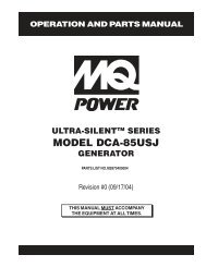
PARTS AND OPERATION MANUALOPERATION AND PARTS MANUALWHISPERWATT TM SERIESMODEL <strong>DCA</strong>-<strong>600SSV</strong>60 Hz GENERATORPARTS LIST NO. C4874303204Revision #0 (07/13/07)THIS MANUAL MUST ACCOMPANYTHE EQUIPMENT AT ALL TIMES.
PROPOSITION 65 WARNINGDiesel engine exhaust and some ofPAGE 2 — <strong>DCA</strong>-<strong>600SSV</strong> — OPERATION AND PARTS MANUAL — REV. #0 (07/13/09)
MQ Power <strong>DCA</strong>-<strong>600SSV</strong>60 Hz AC GeneratorCalifornia Proposition 65 Warning ..................................... 2Reporting Safet Defects ................................................... 3Table of Contents .............................................................. 4Parts Ordering Procedures ............................................... 5Specifications ................................................................... 6Dimensions (Top, Side, Front) .......................................... 7Safety Alert Messages Symbols ................................... 8-9Rules for Safe Operation ........................................... 10-13Generator Decals ....................................................... 14-17Installation ................................................................. 18-19General Information ........................................................ 20Major Components ......................................................... 21Generator Control Panel ............................................ 22-23Engine Operating Panel ............................................. 24-25Output Terminal Panel Familiarization ........................ 26-28Load Application ............................................................. 29Generator Outputs .......................................................... 30Generator Outputs/Gauge Reading ................................. 31Output Terminal Panel Connections ........................... 32-33Pre Setup .................................................................. 34-38Generator Start-up Procedure ( <strong>Manual</strong> MPEC) ........ 39-41Generator Start-up Procedure (Auto MPEC) .................. 42Generator Shutdown Procedure ...................................... 43Maintenance (Engine) ................................................ 44-47Maintenance (Trailer) ................................................. 48-50Trailer Wiring Diagram ................................................ 51-52Generator Wiring Diagram ............................................... 53Generator Wiring Diagram (Main Breaker) ...................... 54Engine Wiring Diagram .............................................. 55-56Engine Troubleshooting .............................................. 57-58Generator Troubleshooting .............................................. 59Engine Contoller Troubleshooting (MPEC) ...................... 60Troubleshooting Diagnostic Lamp ................................... 61Explanation of Codes in Remarks Column ..................... 62Suggested Spare Parts .................................................. 63NOTETABLE OF CONTENTSCOMPONENT DRAWINGSGenerator Assembly .......................................... 64-67Control Box Assembly ........................................ 68-73Engine Radiator Assembly ................................. 74-77Engine Operating Panel Assembly .................... 78-79Output Terminal Assembly ................................. 80-83Battery Assembly ............................................... 84-85Muffler Assembly ............................................... 86-87Fuel Tank Assembly ........................................... 88-89Enclosure #1 Assembly...................................... 90-93Enclosure #2 Assembly...................................... 94-97Enclosure #3 Assembly...................................... 98-99Enclosure (Rubber Seals) .............................. 100-101Nameplate and Decals................................... 102-105Terms and Conditions Of Sale — Parts ................ 106Specification and partnumber are subject tochange without notice.PAGE 4 — <strong>DCA</strong>-<strong>600SSV</strong> — OPERATION AND PARTS MANUAL — REV. #0 (07/13/09)
PARTS ORDERING PROCEDURESwww.mqpower.com❒❒❒❒❒Ordering parts has never been easier!Choose from three easy options:Order via Internet (Dealers Only):Order parts on-line using <strong>Multiquip</strong>’s SmartEquip website!■ View Parts Diagrams■ Order PartsGoto www.multiquip.com and click onOrder Parts to log in and save!Order via Fax (Dealers Only):All customers are welcome to order parts via Fax.Domestic (US) Customers dial:Non-Dealer Customers:Contact your local <strong>Multiquip</strong> Dealer forparts or call 800-427-1244 for help inDealer Account NumberDealer Name and AddressWhen ordering parts, please supply:Shipping Address (if different than billing address)Return Fax NumberApplicable Model NumberOrder via Phone:All orders are treated as Standard Ordersand will ship the same day if received priorWE ACCEPT ALL MAJOR CREDIT CARDS!❒If you have an MQ Account, to obtain aUsername and Password, E-mail us at:parts@multiquip.com.To obtain an MQ Account, contact yourUse the internet and qualify for a 5% Discounton Standard orders for all orders which includeFax your order in and qualify for a 2% Discounton Standard orders for all orders which includeDomestic (US) Dealers Call:Specify Preferred Method of Shipment:✓ UPS/Fed Ex ✓ DHL■ Priority One ✓ Truck■ Ground■ Next DayNote: Discounts Are Subject To ChangeInternational Customers should contacttheir local <strong>Multiquip</strong> Representatives forEffective:Note: Discounts Are Subject To Change<strong>DCA</strong>-<strong>600SSV</strong> — OPERATION AND PARTS MANUAL — REV. #0 (07/13/09) — PAGE 5
<strong>DCA</strong>-<strong>600SSV</strong> — SPECIFICATIONSTable 1. Generator SpecificationsArmatureModelTypeConnection<strong>DCA</strong>-<strong>600SSV</strong>Revolving field, self ventilated,open protected type synchronous generatorStar with NeutralPhase3S tandby Output660 KVA (528 KW)P rime Output600 KVA (480 KW)VoltageVoltage— 1Ø— 3ØFrequencySpeed120, 127, 139, 240, 254, and 277V208, 220, 240, 416, 440, and 480V60 Hz1800 rpmPowerFactor0. 8Aux.AC PowerSingle Phase, 60 HzA ux. Voltage/Output120 VAC/ 4.8 Kw (2.4 kW x 2)D ry Weight16,369 lbs. (7,425 kg. )T otal Weight17,659 lbs. (8,010 kg. )Table 2. Engine SpecificationsNo.ModelTypeof CylindersVOLVO PENTA TAD1642GE4 cycle, water-cooled, direct injection, turbo-chargedwith air to air after cooler6 cylindersB ore x Stroke5.67 in. x 6.50 in. (144 mm x 165 mm)RatedOutput713 HP / 1800 rpmD isplacement948 cu. in. (16,120 cc)StartingElectric 24 VDCC oolant Capacity24.6 gal. (93 liters)L ube Oil Capacity12.7 gal. (48 liters)FuelType#2 Diesel FuelF uel Tank Capacity129 gal. (490 liters)Fuel Consumption33.1gal. (125.2 L)/hr at fullload24.2gal. (91.7 L)/hr at3/4 load17.3gal. (65.4 L)/hr at 1/2load10.5gal. (39.6 L)/hr at1/4 loadBattery12V-200 Ah x 2PAGE 6 — <strong>DCA</strong>-<strong>600SSV</strong> — OPERATION AND PARTS MANUAL — REV. #0 (07/13/09)
<strong>DCA</strong>-<strong>600SSV</strong> — DIMENSIONS (TOP, SIDE AND FRONT)CDEBTOP VIEWAHGFFigure 1. DimensionsSIDE VIEW600IREAR VIEW(CONTROL PANEL VIEW)TABLE 3. DIMENSIONSReferenceLetterDimensionin. (mm.)R eference LetterDimension in. (mm.)A 26.97in. (685 mm. )G 17.32 in. (440 mm. )B 27.36in. (695 mm. )H 39.37 in. (1,000 mm. )JC 39.37in. (1,000 mm. )I 185.04 in. (4,700 mm. )D 17.32in. (440 mm. )J 78.9 in. (2,005 mm. )E 38.98in. (990 mm. )K 65 in. (1,651 mm. )F 38.98 in. (990 mm. )K<strong>DCA</strong>-<strong>600SSV</strong> — OPERATION AND PARTS MANUAL — REV. #0 (07/13/09) — PAGE 7
<strong>DCA</strong>-<strong>600SSV</strong> — SAFETY MESSAGE ALERT SYMBOLSFOR YOUR SAFETY AND THE SAFETY OF OTHERS! HAZARD SYMBOLSSafety precautions should be followed at all times whenoperating this equipment. Failure to read and understand theSafety Messages and Operating Instructions could result ininjury to yourself and others.NOTEBefore using this generator, ensure that the operatingindividual has read and understands all instructions inthis manual.SAFETY MESSAGE ALERT SYMBOLSThe three (3) Safety Messages shown below will inform youabout potential hazards that could injure you or others. TheSafety Messages specifically address the level of exposureto the operator, and are preceded by one of three words:DANGER, WARNING, or CAUTION.DANGERThis Owner's <strong>Manual</strong> has beendeveloped to provide completeinstructions for the safe andefficient operation of theMQPower Model <strong>DCA</strong>-<strong>600SSV</strong>WHISPERWATT GENERATOR.You WILL be KILLED or SERIOUSLY injured if youdo not follow directions.Potential hazards associated with the operation of thisequipment will be referenced with "Hazard Symbols" whichappear throughout this manual, and will be referenced inconjunction with Safety "Message Alert Symbols".WARNING - LETHAL EXHAUST GASESGasoline engine exhaust gases containpoisonous carbon monoxide. This gas iscolorless and odorless, and can causeDEATH if inhaled. NEVER operate thisequipment in a confined area or enclosed structure thatdoes not provide ample free flow air.WARNING - EXPLOSIVE FUELGasoline is extremely flammable, andits vapors can cause an explosion ifignited. DO NOT start the engine nearspilled fuel or combustible fluids.DO NOT fill the fuel tank while the engineis running or hot.DO NOT overfill tank, since spilled fuel could ignite if itcomes into contact with hot engine parts or sparks fromthe ignition system. Store fuel in approved containers, inwell-ventilated areas and away from sparks and flames.NEVER use fuel as a cleaning agent.WARNINGYou COULD be KILLED or SERIOUSLY injured ifyou do not follow directions.CAUTIONYou CAN be injured if you do not follow directionsWARNING - BURN HAZARDSEngine components can generate extremeheat. To prevent burns, DO NOT touch theseareas while the engine is running orimmediately after operations. NEVERoperate the engine with heat shields or heatguards removed.DANGER - ELECTROCUTION HAZARDSDuring operation of this generator, thereexists the possibility of electrocution,electrical shock or burn, which can causesevere bodily harm or even DEATH!PAGE 8 — <strong>DCA</strong>-<strong>600SSV</strong> — OPERATION AND PARTS MANUAL — REV. #0 (07/13/09)
<strong>DCA</strong>-<strong>600SSV</strong> — SAFETY MESSAGE ALERT SYMBOLSWARNING - ROTATING PARTSNEVER operate equipment with covers,or guards removed. Keep fingers, hands,hair and clothing away from all movingparts to prevent injury.CAUTION - RESPIRATORY HAZARDSALWAYS wear approved respiratoryprotection.CAUTION - ACCIDENTAL STARTINGALWAYS place the Engine ON/OFFswitch in the OFF position and removethe ignition key when the pump is not inuse.CAUTION - SIGHT AND HEARING HAZARDSALWAYS wear approved eye andhearing protection.CAUTION - OVER-SPEED CONDITIONSNEVER tamper with the factory settingsof the engine governor or settings.Personal injury and damage to the engineor equipment can result if operating inspeed ranges above maximum allowable.CAUTION - EQUIPMENT DAMAGE MESSAGESOther important messages are provided throughout thismanual to help prevent damage to your generator, otherproperty, or the surrounding environment.NOTEThis generator, other property,or the surrounding environmentcould be damaged if you do notfollow instructions.<strong>DCA</strong>-<strong>600SSV</strong> — OPERATION AND PARTS MANUAL — REV. #0 (07/13/09) — PAGE 9
<strong>DCA</strong>-<strong>600SSV</strong> — RULES FOR SAFE OPERATIONDANGER - READ THIS MANUAL!Failure to follow instructions in this manual may lead toserious injury or even DEATH! This equipment is to beoperated by trained and qualified personnel only! Thisequipment is for industrial use only.The following safety guidelines should always be used whenoperating the <strong>DCA</strong>-<strong>600SSV</strong> Whisperwatt Generator.General Safety:■ DO NOT operate or service thisequipment before reading this entiremanual.The operator MUST BE familiar with proper safetyprecautions and operations techniques before usinggenerator.■ This equipment should not be operated by persons under18 years of age.■ NEVER operate this equipment without proper protectiveclothing, shatterproof glasses, steel-toed boots and otherprotective devices required by the job.■ NEVER operate this equipment when notfeeling well due to fatigue, illness or takingmedicine.■ NEVER operate this equipment under the influence ordrugs or alcohol.■ NEVER use accessories or attachments, which are notrecommended by MQ Power for this equipment. Damageto the equipment and/or injury to user may result.■ Manufacturer does not assume responsibility for anyaccident due to equipment modifications. Unauthorizedequipment modification will void all warranties.■ Whenever necessary, replace nameplate, operation andsafety decals when they become difficult read.■ ALWAYS check the machine for loosened threads or boltsbefore starting.■ NEVER operate the generator in an explosive atmosphereor near combustible materials. An explosion or fire couldresult causing severe bodily harm or even death.■ NEVER touch the hot exhaust manifold, muffleror cylinder. Allow these parts to cool beforeservicing engine or generator.■ High Temperatures – Allow the engineto cool before performing service andmaintenance functions. Contact withhot! components can cause seriousburns.■ The engine of this generator requires an adequate freeflow of cooling air. NEVER operate the generator in anyenclosed or narrow area where free flow of the air isrestricted. If the air flow isrestricted it will cause seriousdamage to the generator orengine and may cause injuryto people. The generatorengine gives off DEADLYcarbon monoxide gas.■ DO NOT place hands or fingers inside generator enginecompartment when engine is running.■ NEVER run engine without air filter. Severe engine damagemay occur.■ DO NOT leave the generator running in the manual modeunattended.■ Refer to the VOLVO Engine Owner's <strong>Manual</strong> for enginetechnical questions or information.■ ALWAYS store equipment properly when it is not beingused. Equipment should be stored in a clean, dry locationout of the reach of children.PAGE 10 — <strong>DCA</strong>-<strong>600SSV</strong> — OPERATION AND PARTS MANUAL — REV. #0 (07/13/09)
<strong>DCA</strong>-<strong>600SSV</strong> — RULES FOR SAFE OPERATIONGenerator GroundingTo guard against electrical shock and possible damage tothe equipment, it is important to provide a good EARTHground.Article 250 (Grounding) of the National Electrical Code(NEC) provides guide lines for proper grounding and specifiesthat the cable ground shall be connected to the groundingsystem of the building as close to the point of cable entryas practical.The following safety recommendations should also befollowed:■ ALWAYS make sure generator is properly grounded.■ NEVER use gas piping as an electrical ground.■ ALWAYS make sure that electrical circuits are properlygrounded per the National Electrical Code (NEC) andlocal codes before operating generator. Severe injury orDEATH! by electrocution can result from operating anungrounded generator.■ ALWAYS be sure to use the ground terminal (green wire)when connecting a load to the U,V, and W outputterminal lugs.Electrical Safety■ ALWAYS have a qualified electrician perform thegenerator wiring installation.■ ALWAYS make sure generator installation is accordancewith the National Electrical Code (NEC) and local codesbefore operating generator.■ NEVER use a defective or frayed power cable. Checkthe cable for cuts in the insulation.■ NEVER use a extension cord that is frayed or damagedwhere the insulation has been cut.■ ALWAYS make certain that proper extension cord hasbeen selected for the job. See Table 5.■ NEVER power cables or cords lay in water.■ NEVER stand in water while AC power from the generatoris being transfer to a load.DANGER - ELECTROCUTION HAZARDSDuring operation of this generator, thereexists the possibility of electrocution,electrical shock or burn, which can causesevere bodily harm or even DEATH!To avoid these hazards:NEVER use damaged or worn cables when connectingequipment to the generator. Make sure power connectingcables are securely connected to the generator’s outputterminals, insufficient tightening of the terminal connectionsWETmay cause damage to the generatorHANDSand electrical shock.NEVER grab or touch a live powercord with wet hands.NEVER touch output terminalsduring operation. This is extremelydangerous. ALWAYS stop themachine and place the circuitbreaker in the OFF position whencontact with the output terminals isrequired.Backfeed to a utility system cancause electrocution and orproperty damage. DO NOT connectto any building's electrical systemexcept through an approved deviceor after building main switch isopened. ALWAYS have a licensedelectrician perform the installationPOWERCORD(POWER ON)U N V<strong>DCA</strong>-<strong>600SSV</strong> — OPERATION AND PARTS MANUAL — REV. #0 (07/13/09) — PAGE 11
<strong>DCA</strong>-<strong>600SSV</strong>— RULES FOR SAFE OPERATIONMaintenance Safety■ The electrical voltage required to operate the generatorcan cause severe injury or even death through physicalcontact with live circuits. Turn all circuit breakers OFFbefore performing maintenance on the generator.■ NEVER lubricate components or attempt service on arunning machine.■ ALWAYS disconnect the NEGATIVE battery terminalbefore performing service on the generator.■ Follow all Battery Safety Guidelines listed in this manualwhen handleing or servicing the generator.■ ALWAYS allow the machine a proper amount of time tocool before servicing.■ Keep the machinery in proper running condition.■ Fix damage to the machine immediately and alwaysreplace broken parts.■ ALWAYS service air cleaner frequently to prevent enginemalfunction.WARNING - BURN HAZARDSTo prevent burns, DO NOT touch or open any of the belowmentioned components while the engine isrunning or immediately after operations.Always allow sufficient time for the engineand generator to cool before performingmaintenance.■ Radiator Cap - Removing the radiator cap while theengine is hot will result in high pressurized, boiling waterto gush out of the radiator, causing severe scalding toany persons in the general area of the generator.■ Coolant Drain Plug - Removing the coolant drain plugwhile the engine is hot will result in hot coolant gushingout of the coolant drain plug, therefore causing severescalding to any persons in the general area of thegenerator.■ Engine Oil Drain Plug - Removing the engine oil drainplug while the engine is hot will result in hot oil gushingout of the oil drain plug, therefore causing severescalding to any persons in the general area of thegenerator.Battery SafetyUse the following guidelines when handling the battery:■ The battery contains acids that cancause injury to the eyes and skin. Toavoid eye irritation, always wear safetyglasses.■ Use well insulated gloves when picking up the battery.DANGER - EXPLOSION HAZARDSThe risk of an explosion exists when performing serviceon the battery. To avoid severe injury or DEATH:■ DO NOT drop the battery. Thereis the possibility of risk that thebattery may explode.■ DO NOT expose the battery toopen flames, sparks, cigarettesetc. The battery contains combustible gases and liquids.If these gases and liquids come in contact with a flameor spark, an explosion could occur.■ ALWAYS keep the battery charged. If the battery is notcharged a buildup of combustible gas will occur.■ ALWAYS keep battery charging and cables in goodworking condition. Repair or replace all worn cables.■ ALWAYS recharge the battery in an vented airenvironment, to avoid risk of a dangerous concentrationof combustible gases.■ In case the battery liquid (dilute sulfuric acid) comes incontact with clothing or skin, rinse skin or clothingimmediately with plenty of water.■ In case the battery liquid (dilute sulfuric acid) comes incontact with your EYES, rinse eyes immediately withplenty of water and contact the nearest doctor or hospitalto seek medical attention.PAGE 12 — <strong>DCA</strong>-<strong>600SSV</strong> — OPERATION AND PARTS MANUAL — REV. #0 (07/13/09)
<strong>DCA</strong>-<strong>600SSV</strong> — RULES FOR SAFE OPERATIONTowing & Transporting SafetyTo reduce the possibility of an accident while transportingthe generator on public roads, always make sure the trailerthat supports the generator and the towing vehicle are ingood operating condition and both units are mechanicallysound.The following list of safety precautions should be followedwhen towing your generator:CAUTION - FOLLOW TOWING REGULATIONSCheck with your local county or state safety towingregulations, in addition to meeting Department ofTransportation (DOT) Safety Towing Regulations, beforetowing your generator.■ ALWAYS shutdown engine before transporting.■ Tighten both fuel tank caps securely.■ If generator is mounted on a trailer, make sure trailercomplies with all local and state safety transportationlaws. Follow the listed Towing & Transporting Safetyguidelines for basic towing techniques.■ Make sure the hitch and coupling of the towing vehicleare rated equal to, or greater than the trailer "gross vehicleweight rating.”■ ALWAYS inspect the hitch and coupling for wear. NEVERtow a trailer with defective hitches, couplings, chains etc.■ Check the tire air pressure on both towing vehicle andtrailer. Trailer tires should be inflated to 50 psi cold.Also check the tire tread wear on both vehicles.■ ALWAYS make sure the trailer is equipped with a "SafetyChain".■ ALWAYS attach trailer’s safety chains to towing vehicleproperly.■ ALWAYS make sure the vehicle and trailer directional,backup, brake, and trailer lights are connected andworking properly.■ DOT Requirements include the following:• Connect and test electric brake operation.• Secure portable power cables in cable tray with tiewraps.■ The maximum speed for highway towing is 55 MPHunless posted otherwise. Recommended off-road towingis not to exceed 15 MPH or less depending on type ofterrain.■ Place chock blocks underneath wheel to prevent rolling,while parked.■ Use the trailer’s swivel jack to adjust the trailer height toa level position while parked.■ Avoid sudden stops and starts. This can cause skidding,or jack-knifing. Smooth, gradual starts and stops willimprove towing.■ Avoid sharp turns.■ Trailer should be adjusted to a level position at all timeswhen towing.■ Raise and lock trailer wheel stand in up position whentransporting.■ The maximum speed for highway towing is 55 MPHunless posted otherwise. Recommended off-road towingis not to exceed 15 MPH or less depending on type ofterrain.■ Place support blocks underneath the trailer’s bumper toprevent tipping, while parked.■ Avoid sharp turns to prevent rolling.■ DO NOT transport generator with fuel in tank.Emergencies■ ALWAYS know the location of thenearest fire extinguisher.■ ALWAYS know the location of thenearest and first aid kit.■ ALWAYS know the location of thenearest phone or keep a phone onthe job site, in case of emergencies.■ ALWAYS have easy access to the phonenumbers of the nearest Ambulance, Doctorand Fire Department. This information willbe invaluable in the case of an emergency.<strong>DCA</strong>-<strong>600SSV</strong> — OPERATION AND PARTS MANUAL — REV. #0 (07/13/09) — PAGE 13
<strong>DCA</strong>-<strong>600SSV</strong> — GENERATOR DECALSMachine Safety DecalsThe <strong>DCA</strong>-<strong>600SSV</strong> generator is equipped with a number of safety decals. These decals are provided for operator safety andmaintenance information. The illustrations below and on the preceding pages shows the decals as they appear on the machine.Should any of these decals become unreadable, replacements can be obtained from your dealer.Figure 2. Generator DecalsPAGE 14 — <strong>DCA</strong>-<strong>600SSV</strong> — OPERATION AND PARTS MANUAL — REV. #0 (07/13/09)
<strong>DCA</strong>-<strong>600SSV</strong> — GENERATOR DECALSFigure 2. Generator Decals<strong>DCA</strong>-<strong>600SSV</strong> — OPERATION AND PARTS MANUAL — REV. #0 (07/13/09) — PAGE 15
<strong>DCA</strong>-<strong>600SSV</strong> — GENERATOR DECALSFigure 2. Generator DecalsPAGE 16 — <strong>DCA</strong>-<strong>600SSV</strong> — OPERATION AND PARTS MANUAL — REV. #0 (07/13/09)
<strong>DCA</strong>-<strong>600SSV</strong> — GENERATOR DECALSFigure 3. Generator Decals<strong>DCA</strong>-<strong>600SSV</strong> — OPERATION AND PARTS MANUAL — REV. #0 (07/13/09) — PAGE 17
<strong>DCA</strong>-<strong>600SSV</strong> — INSTALLATION<strong>DCA</strong>-<strong>600SSV</strong> — INSTALLATIONFigure 4.Typical Generator Grounding ApplicationPAGE 18 — <strong>DCA</strong>-<strong>600SSV</strong> — OPERATION AND PARTS MANUAL — REV. #0 (07/13/09)
<strong>DCA</strong>-<strong>600SSV</strong> — INSTALLATIONOutdoor InstallationInstall the generator in a area that is free of debris,bystanders, and overhead obstructions. Make sure thegenerator is on secure level ground so that it cannot slide orshift around. Also install the generator in a manner so thatthe exhaust will not be discharged in the direction of nearbyhomes.The installation site must be relatively free from moistureand dust. All electrical equipment should be protected fromexcessive moisture. Failure to do will result in deteriorationof the insulation and will result in short circuits and grounding.Foreign materials such as dust, sand, lint and abrasivematerials have a tendency to cause excessive wear to engineand alternator parts.CAUTION - EXHAUST HAZARDPay close attention to ventilation when operating thegenerator inside tunnels and caves. The engine exhaustcontains noxious elements. Engine exhaust must be routedto a ventilated area.Generator GroundingTo guard against electrical shock and possible damage tothe equipment, it is important to provide a good EARTHground.Article 250 (Grounding) of the National Electrical Code (NEC)provides guide lines for proper grounding and specifies thatthe cable ground shall be connected to the grounding systemof the building as close to the point of cable entry aspractical.NEC articles 250-64(b) and 250-66 set the followinggrounding requirements:1. Use one of the following wire types to connect thegenerator to earth ground.a. Copper - 10 AWG (5.3 mm 2 ) or larger.b. Aluminum - 8 AWG (8.4 mm 2 ) or larger.2. When grounding the generator (Figure 4) connect theground cable between the lock washer and the nut onthe generator and tighten the nut fully. Connect the otherend of the ground cable to earth ground.3. NEC article 250-52(c) specifies that the earth groundrod should be buried aminimum of 8 ft. into the ground.Indoor InstallationExhaust gases from diesel engines are extremely poisonous.Whenever an engine is installed indoors the exhaust fumesmust be vented to the outside. The engine should be installedat least two feet from any outside wall. Using an exhaustpipe which is too long or too small can cause excessiveback pressure which will cause the engine to heat excessivelyand possibly burn the valves.MountingThe generator must be mounted on a solid foundation (suchas concrete) and set firmly on the foundation to isolatevibration of the generator when it is running. The generatormust set at least 6 inches above the floor or grade level (inaccordance to NFPA 110, Chapter 5-4.1). DO NOT removethe metal skids on the bottom of the generator. They are toresist damage to the bottom of the generator and to maintainalignment.NOTEWhen connecting the generator toany buildings electrical systemALWAYS consult with a licensedelectrician.<strong>DCA</strong>-<strong>600SSV</strong> — OPERATION AND PARTS MANUAL — REV. #0 (07/13/09) — PAGE 19
<strong>DCA</strong>-<strong>600SSV</strong> — GENERAL INFORMATION<strong>DCA</strong>-<strong>600SSV</strong>Whisperwatt Series FamiliarizationGeneratorThe MQ Power Model <strong>DCA</strong>-<strong>600SSV</strong> is a 528 kW generator(Figure 5) that is designed as a high quality portable (requiresa trailer for transport) power source for telecom sites, lightingfacilities, power tools, submersible pumps and otherindustrial and construction machinery.Engine Operating PanelThe “Engine Operating Panel” is provided with the following:■ Tachometer/Hour Meter Gauge■ Water Temperature Gauge / Water Temp. Alarm Lamp■ Oil Pressure Gauge / Oil Pressure Alarm Lamp■ Charging Alarm Lamp■ Fuel Level Gauge / Low Fuel Warning Alarm Lamp■ Pre-Heat Button / Pre-Heat Lamp■ Air Filter Alarm Lamp■ Engine Speed Switch■ Battery Switch■ Emergency Stop ButtonGenerator Control PanelThe “Generator Control Panel” is provided with the following:■ Frequency Meter (Hz)■ AC Ammeter (Amps)■ AC Voltmeter (Volts)■ Ammeter Change-Over Switch■ Voltmeter Change-Over Switch■ Voltage Regulator■ Panel Light/Panel Light Switch■ 3-Pole, 1,600 amp Main Circuit Breaker■ Engine Control Unit (Computer Controlled)■ “Control Box” (Located Behind Gen. Control Panel)■ Automatic Voltage Regulator■ Current Transformer■ Over-Current Relay■ Voltage Rectifer■ Starter Relay■ Voltage Change-over BoardOutput Terminal PanelThe “Output Terminal Panel” is provided with the following:■■■■■■■■Three 120/240V output receptacles (CS-6369), 50AThree auxilliary circuit breakers, 50ATwo 120V output receptacles (GFCI), 20ATwo GFCI circuit breakers, 20AFour output terminal boards (3Ø power)Ground terminalBattery Charger (Optional)Water Heater (Optional)Open Delta Excitation SystemThe <strong>DCA</strong>-<strong>600SSV</strong> generator is equipped with the state ofthe art "Open-Delta" excitation system. The open deltasystem consist of an electrically independent winding woundamong stationary windings of the AC output section.There are four connections of the open delta A, B, C and D.During steady state loads, the power from the voltageregulator is supplied from the parallel connections of A to B,A to D, and C to D. These three phases of the voltage inputto the voltage regulator are then rectified and are theexcitation current for the exciter section.When a heavy load, such as a motor starting or a shortcircuit occurs, the automatic voltage regulator (AVR)switches the configuration of the open delta to the seriesconnection of B to C. This has the effect of adding thevoltages of each phase to provide higher excitation to theexciter section and thus better voltage response during theapplication of heavy loads.The connections of the AVR to the AC output windings arefor sensing only. No power is required from these windings.The open-delta design provides virtually unlimited excitationcurrent, offering maximum motor starting capabilities. Theexcitation does not have a "fixed ceiling" and respondsaccording the demands of the required load.EngineThe <strong>DCA</strong>-<strong>600SSV</strong> is powered by a 4 cycle, water cooled,turbocharged VOLVO Model PENTA TAD1642GE DieselEngine. This engine is designed to meet every performancerequirement for the generator. Reference Table 2 for enginespecifications.In keeping with MQ Power's policy of constantly improvingits products, the specifications quoted herein are subject tochange without prior notice.Electronic Governor SystemThe electric governor system controls the RPMs of the engine.When the engine demand increases or decreases, thegovernor system regulates the frequency variation to ±.25%.Extension CablesWhen electric power is to be provided to various tools orloads at some distance from the generator, extension cordsare normally used. Cables should be sized to allow fordistance in length and amperage so that the voltage dropbetween the generator and point of use (load) is held to aminimum. Use the cable selection chart (Table 6) as a guidefor selecting proper extension cable size.PAGE 20 — <strong>DCA</strong>-<strong>600SSV</strong> — OPERATION AND PARTS MANUAL — REV. #0 (07/13/09)
<strong>DCA</strong>-<strong>600SSV</strong> — MAJOR COMPONENTS<strong>DCA</strong>-<strong>600SSV</strong> — MAJOR COMPONENTSTable 4. Generator Major ComponentsITEM NO.DESCRIPTION1 Enclosure Assembly2 Air Cleaner Assembly3 Muffler Assembly4 Fuel Tank Assembly5 Engine and Radiator Assembly6 Battery Assembly7 Generator Assembly8 Output Terminal Assembly9 Generator Control Panel Assembly10 Engine Operating Panel AssemblyFigure 5. Major Components<strong>DCA</strong>-<strong>600SSV</strong> — OPERATION AND PARTS MANUAL — REV. #0 (07/13/09) — PAGE 21
<strong>DCA</strong>-<strong>600SSV</strong> — GENERATOR CONTROL PANEL1210 1134514AUTOMANUALHZAVOFF/RESETLOW OIL PRESSUREHIGH COOLANT TEMPERATUREOVERCRANKOVERSPEEDENGINE RUNNINGMOOOOO-20001Q6 78912 13Figure 6. Generator Control PanelThe definitions below describe the controls and functions ofthe <strong>DCA</strong>-<strong>600SSV</strong> " Control Panel " (Figure 6).1. Pilot Lamp – Indicates that the generator is workingproperly.2. Panel Light – Normally used in dark areas or at nighttime. When activated, panel lights will illuminate. Whenlit this light will make it easier to read the meters andgauges. When the generator is not in use be sure toturn the panel light switch to the OFF position.3. Frequency Meter – Indicates the output frequency inhertz (Hz). Normally 60 Hz ±1 Hz .4. AC Ammeter – Indicates the amount of current theload is drawing from the generator.5. AC Voltmeter – Indicates the single phase outputvoltage present at the UVWO terminals. .6. Ammeter Change-Over Switch – This switch allowsthe AC ammeter to indicate the current flowing to theload connected to any phase of the output terminals,or to be switched off.7. Voltmeter Change-Over Switch – This switch allowsthe AC voltmeter to indicate phase to phase voltagebetween any two phases of the output terminals or tobe switched off8. Panel Light Switch – When activated, this switch willturn on the luminate the control panel.9. Voltage Regulator Control – Allows manualadjustment of the generator’s output voltagePAGE 22 — <strong>DCA</strong>-<strong>600SSV</strong> — OPERATION AND PARTS MANUAL — REV. #0 (07/13/09)
<strong>DCA</strong>-<strong>600SSV</strong> — GENERATOR CONTROL PANEL10. Circuit Breaker OFF Lamp – When the circuitbreaker ON switch is placed in the OFF position thislamp will be turned OFF.11. Circuit Breaker ON Lamp – When the circuit breakerON switch is placed in the ON position this lamp willbe turned ON.12. Circuit Breaker OFF Switch – Press this switch toplace the 1600 amp circuit breaker in the open (OFF)position.13. Circuit Breaker ON Switch – Press this switch toplace the 1600 amp circuit breaker in the closed (ON)position.14. Auto On/Off Engine Controller (MPEC) – Thiscontroller has a vertical row of status LED's (inset),that when lit, indicates that anengine malfunction (fault) hasbeen detected. When a faulthas been detected the enginecontroller will evaluate the faultand all major faults willshutdown the generator.During cranking cycle , TheMPEC will attempt to crankthe engine for 10 secondsbefore disengaging.During cranking cycle , The MPEC will attempt to crankthe engine for 10 seconds before disengaging. If the enginedoes not engage (start) by the third attempt, the engine willbe shutdown by the engine controller’s " Over CrankProtection" mode. If the engine engages at a speed (RPM's)that is not safe, the controller will shutdown the engine byinitializing the "Over Speed Protection" mode.Also the MPEC will shutdown the generator in the event oflow oil pressure, high coolant temperature, low coolant level,and loss of magnetic pickup. These conditions can beobserved by monitoring the LED status indicators on thefront of the MPEC module.A. Off/<strong>Manual</strong>/Auto Switch – This switch controls therunning of the generator. If this switch is left in the "OFF"position, the generator will not run. When this switch isset to the manual position, the generator will startimmediately.If the generator is to be connected to a building’s ACpower source via an automatic transfer switch(isolation), place the switch in the AUTO position. Inthis position, should an outage occur, the automatictransfer switch (ATS) will start the generatorautomatically via the generator’s auto-start contactsconnected to the ATS’s start contacts. Please refer toyour ATS installation manual for further instructions forthe correct installation of the auto-start contacts of thegenerator to the ATS.B. Low Oil Pressure – Indicates the engine pressurehas fallen below 15 psi. The oil pressure is detectedusing variable resistive values from the oil pressuresending unit. This is considered a major fault and willshut down the generator.C. High Coolant Temperature – Indicates the enginetemperature has exceeded 215°F. The enginetemperature is detected using variable resistive valuesfrom the temperature sending unit. This is considereda major fault and will shut down the generator.D. Overcrank Shutdown – Indicates the unit hasattempted to be started a pre- programmed number oftimes, and has failed to start. The number of cyclesand duration are programmable. Typical programmablestart settings is 3 cycles with a 10 second duration.This is considered a major fault and will shut downthe generator.E. Overspeed Shutdown – Indicates that the engine isrunning at an unsafe speed. This is considered a majorfault.F. Engine Running – Indicates that engine is running ata safe operating speed.<strong>DCA</strong>-<strong>600SSV</strong> — OPERATION AND PARTS MANUAL — REV. #0 (07/13/09) — PAGE 23
<strong>DCA</strong>-<strong>600SSV</strong> — ENGINE OPERATING PANEL1 5 6 73 4WATER TEMP. OIL PRESS. FUEL LEVEL CHARGE AIR FILTERBATTERY SWITCHONPRE-HEATLAMPEMERGENCYSTOPENGINE SPEEDHIGHTACHOMETEROFFPRE-HEATBUTTONLOW11 2 89 10Figure 7. Engine Operating PanelsPAGE 24 — <strong>DCA</strong>-<strong>600SSV</strong> — OPERATION AND PARTS MANUAL — REV. #0 (07/13/09)
<strong>DCA</strong>-<strong>600SSV</strong> — ENGINE OPERATING PANELThe definitions below describe the controls and functions of the<strong>DCA</strong>-<strong>600SSV</strong> " Engine Operating Panels " (Figure 7).1. Tachometer – Indicates engine speed in RPM’s for 60 Hzoperation. This meter should indicate 1800 RPM’s whenthe rated load is applied. In addition a built in hour meterwill record the number of operational hours that thegenerator has been in use.2. Engine Warning Display (LED) Module – This moduledisplay’s the following engine failures:A. Overheat Lamp – This lamp goes ON whenthe cooling water temperature rises abnormally.If the lamp goes ON during normal operation ofthe generator, the emergency shutdown devicewill stop the engine automatically.C. Low Fuel Level Lamp – When this lamp isON, it is time to stop the engine and add fuel.Remember to let the engine cool beforeadding fuel.WATER TEMP.B. Low Oil Pressure Lamp – During normal operation of thegenerator this lamp should remain OFF. When the Auto-OFF/Reset-<strong>Manual</strong> switch is set to the“<strong>Manual</strong>” position to start the engine, the lampwill illuminate. After the oil pressure rises afterstart-up the lamp will go OFF. If this lamp isever illuminated (ON) during normal operationof the generator, the emergency shutdownOIL PRESS.device will stop the engine automatically.FUEL LEVEL3. Pre-Heat Lamp – Indicates that the glow plugs of thediesel engine are hot and the engine is ready to be started.4. Emergency Stop Button – Push this button inward tostop the engine in the event of an emergency. DO NOTuse this button as a normal means of stopping the engine.5. Oil Pressure Gauge – During normal operation this gaugebe should read in the “GREEN” zone. When starting thegenerator the oil pressure mar read a little bit higher, butafter the engine warms up the oil pressure should return tothe green zone.6. Water Temperature Gauge – During normal operationthis gauge be should read in the “GREEN” zone.7. Fuel Level Gauge – Indicates amount of diesel fuelremaining.8. Battery Switch – This switch should be set to the ONposition during normal operation. When the engine hasbeen stop, place this switch in the OFF position. DO NOTturn this switch during normal operation, it could causedamage to the electrical equipment.9. Preheat Switch – Press on to heat glow plugs in coldweather conditions.10. Engine Speed Switch – This switch changes the enginespeed from idle to normal.11. Hour Meter Switch - Press this pushbutton switch toactivate hour meter. Indicates the number hoursequipment has been in operational use.D. Charge Lamp – This lamp goes ON whenthe electrical charging system is not workingproperly.BATTERYE. Clogged Air Filter Lamp – This lamp goesON when the air filter is clogged. If this lampgoes ON during normal operation of thegenerator, stop the engine and replace the airfilter.AIR FILTER<strong>DCA</strong>-<strong>600SSV</strong> — OPERATION AND PARTS MANUAL — REV. #0 (07/13/09) — PAGE 25
<strong>DCA</strong>-<strong>600SSV</strong> — OUTPUT TERMINAL FAMILIARIZATIONOutput Terminal FamiliarizationThe “Output Terminal Panel ” (Figure 8) is provided withthe following:• Three 240/139V output receptacles, 50 amp• Three AUX. circuit breakers 240V @50 amps• Two 120V GFCI receptacles, 20 amp• Two (2) GFCI circuit breakers 120V@ 20 amps• Eight (16) output terminal lugsOutput Terminal PanelShown below (Figure 8) is the Output Terminal Panel , liftup on the cover to gain access to receptacles and terminallugs.NOTETerminal legs "O" and "Ground"are considered bonded grounds.Figure 8. Output Terminal PanelPAGE 26 — <strong>DCA</strong>-<strong>600SSV</strong> — OPERATION AND PARTS MANUAL — REV. #0 (07/13/09)
<strong>DCA</strong>-<strong>600SSV</strong> — OUTPUT TERMINAL PANEL FAMILIARIZATION120 VAC GFCI ReceptaclesThere are two 120 VAC, 20 amp GFCI (Duplex Nema 5-20R)recepacles provided on the output terminal panel. Thesereceptacles can be accessed in any voltage change-overboard position. Each receptacle is protected by a 20 ampcircuit breaker. These breakers are located directly abovethe GFCI receptacles. Remember the load output (current)of both GFCI receptacles is dependent on the loadrequirements of the UVWO terminals.Pressing the reset button resets the GFCI receptacle afterbeing tripped. Pressing the "Test Button" (See Figure 9) inthe center of the receptacle will check the GFCI function.Both receptacles should be tested at least once a month.Each auxiliary receptacle is protected by a 50 amp circuitbreaker. These breakers are located directly above the GFCIreceptacles. Remember the load output (current) on all threereceptacles is dependent on the load requirements of theUVWO terminals.Turn the voltage regulator control knob (Figure 11) on thecontrol panel to obtain the desired voltage. Turning the knobclockwise will increase the voltage, turning the knob counterclockwisewill decrease the voltage.Figure 11. Voltage Regulator Control KnobFigure 9 G.F.C.I. ReceptacleTwist Lock Dual Voltage 240/139 VAC ReceptaclesThere are three 240/139 VAC, 50 amp auxiliary twist-lock(CS-6369) receptacles (Figure 10) provided on the outputterminal panel. These receptacles can be accessed in anyvoltage change-over board position.Figure 10. 240/139 VAC Twist-LockAuxiliary Receptacles<strong>DCA</strong>-<strong>600SSV</strong> — OPERATION AND PARTS MANUAL — REV. #0 (07/13/09) — PAGE 27
<strong>DCA</strong>-<strong>600SSV</strong> — OUTPUT TERMINAL PANEL FAMILIARIZATIONConnecting LoadsLoads can be connected to the generator by the UVWO terminallugs or the convenience receptacles. (See Figure 12). Makesure to read the operation manual before attempting to connecta load to the generator.To protect the UVWO output terminals from overload, a 3-pole, 1,600 amp, main circuit breaker is provided. Makesure to switch ALL circuit breakers to the "OFF" positionprior to starting the engine.Over Current RelayAn over current relay (Figure 13) is connected to the maincircuit breaker. In the event of an overload, both the circuitbreaker and the over current relay may trip. If the circuitbreaker can not be reset, the reset button on the over currentrelay must be pressed. The over current relay is locatedin the control box.Figure 13. Over Current RelayMaximum Power Output (KW)The entire load connected to the UVWO output terminal lugs,duplex and auxiliary receptacles must not exceed 528 kW instandby or 480 kW in prime output.Figure 12. Connecting LoadsPAGE 28 — <strong>DCA</strong>-<strong>600SSV</strong> — OPERATION AND PARTS MANUAL — REV. #0 (07/13/09)
<strong>DCA</strong>-<strong>600SSV</strong>— LOAD APPLICATIONSingle Phase LoadAlways be sure to check the nameplate on the generatorand equipment to insure the wattage, amperage andfrequency requirements are satisfactorily supplied by thegenerator for operating the equipment.Generally, the wattage listed on the nameplate of theequipment is its rated output. Equipment may require 130—150% more wattage than the rating on the nameplate, asthe wattage is influenced by the efficiency, power factor andstarting system of the equipment.NOTEIf wattage is not given on the equipment'sname plate, approximate wattage may bedetermined by multiplying nameplatevoltage by the nameplate amperage.WATTS = VOLTAGE x AMPERAGEThe power factor of this generator is 0.8. See Table 5 belowwhen connecting loads.Current inAmperesTable 6. Cable Selection (60 Hz, Single Phase Operation)LoadIn WattsAt 120VoltsTable 5. Power Factor By LoadTypeOf LoadAt 240VoltsPower FactorSingle-phaseinduction motors0.4 - 0.75Electriclampsheaters, incandescent1.0Fluorescentlamps, mercury lamps 0.4 - 0. 9Electronic devices, communicationequipment1.0Commonpower tools0. 8Maximum Allowable Cable Length# 10 Wire # 12 Wire# 14 Wire#16 Wire2.53006001000ft.600ft.375ft.250 ft.Three Phase LoadWhen calculating the power requirements for 3-phase poweruse the following equation:NOTEMotors and motor-drivenequipment draw much greatercurrent for starting than duringoperation.An inadequate size connecting cable which cannot carry therequired load can cause a voltage drop which can burn outthe appliance or tool and overheat the cable. See Table 5.• When connecting a resistance load such as anincandescent lamp or electric heater, a capacity of up tothe generating set’s rated output (kW) can be used.• When connecting a fluorescent or mercury lamp, acapacity of up to the generating set’s rated output (kW)multiplied by 0.6 can be used.• When connecting an electric drill or other power tools,pay close attention to the required starting currentcapacity.When connecting ordinary power tools, a capacity of up tothe generating set’s rated output (kW) multiplied by 0.8 canbe used.DANGER - ELECTRICAL SYSTEM HAZARDSBefore connecting this generator to any building’s electricalsystem, a licensed electrician must install an isolation(transfer) switch. Serious damage to the building’selectrical system may occur without this transfer switch.5 6001200500ft.300ft.200ft.125 ft.7.59001800350ft.200ft.125ft.100 ft.1012002400250ft.150ft.100 ft.1518003600150ft.100ft.65 ft.2024004800125ft.75ft.50 ft.C AUTION: Equipment damage can result from low voltage.NOTEIf 3Ø load (kVA) is not given onthe equipment nameplate,approximate 3Ø load outputmaybe determined by multiplyingvoltage by amperage by 1.732.<strong>DCA</strong>-<strong>600SSV</strong> — OPERATION AND PARTS MANUAL — REV. #0 (07/13/09) — PAGE 29
<strong>DCA</strong>-<strong>600SSV</strong> — GENERATOR OUTPUTSGenerator Output VoltagesA wide range of voltages are available to supply voltage formany different applications. Voltages are selected by applyingjumpers (6) to the voltage change-over board (Figure 15).To obtain some of the voltages as listed in Table 7 (seebelow) will require a fine adjustment using the voltage regulator(VR) control knob located on the control panel.Voltage Change-Over BoardThe voltage change-over board (Figure 14) is located onthe control box, behind the generator control panel. Thisboard has been provided for ease of voltage selection.Maximum AmpsTable 8 shows the maximum amps the generator can provide.DO NOT exceed the maximum amps as listed.Table 8.Model:RatedVoltageMaximum Amps<strong>DCA</strong><strong>600SSV</strong>Maximum AmpsSingle Phase 120VoltSingle Phase 240VoltThree Phase240 VoltThree Phase480 Volt1333.3 amps (4 wire)666.7 amps (4 wire)1443.4 amps721.7 ampsFigure 14. Voltage Change-Over Board240V ConfigurationDANGER - CHANGING JUMPER PLATESNEVER attempt to place jumper plates on the voltagechange-over board while the generator is in operation. Thereexists the possibility of electrocution, electrical shock orburn, which can cause severe bodily harm or even death!Table 7. Generator Available VoltagesThree-PhaseSingle-Phase208V220V240V416V440V480V120V127V139V240V254V277VPAGE 30 — <strong>DCA</strong>-<strong>600SSV</strong> — OPERATION AND PARTS MANUAL — REV. #0 (07/13/09)
<strong>DCA</strong>-<strong>600SSV</strong> — GENERATOR OUTPUTS/GAUGE READINGHow to Read the AC Ammeter and AC Voltage Gauges.The AC ammeter and AC voltmeter gauges are controlledby the Ac ammeter and AC voltmeter change-over switches.Both of these switches are located on the generator controlpanel and DO NOT effect the generator output. They areprovided to help observe how much power is being supplied,produced at the UVWO terminals lugs.Before taking a reading from either gauge, configure the voltagechange-over board which produces the desiredoutputvoltage. When the voltage change-over board isjumpered for 3Ø, 240V operation (See Figure 15).AC Ammeter Gauge ReadingPlace the AC Ammeter Change-Over Switch (Figure 18)in the U position and observe the current reading (load drain)on the U terminal as indicated in the AC Ammeter Gauge(Figure 19). This process can be repeated for terminals Vand W.02040A6075Figure 18. AC AmmeterChange-Over SwitchFigure 19. AC Ammeter(Amp reading on U lug)Figure 15. Voltage Change-Over Board240V/3Ø ConfigurationAC Voltmeter Gauge ReadingPlace the AC Voltmeter Change-Over Switch (Figure 16)in the W-U position and observe the phase to phase voltagereading between the W and U terminals as indicated in theAC Voltmeter Gauge (Figure 17).NOTEThe ammeter and voltmetergauges will only show a readingwhen the Output TerminalLugs are connected to a loadand in use.Figure 16. AC VoltmeterChange-Over SwitchFigure 17 AC VoltmeterGauge(Volt reading on W-U Lug)<strong>DCA</strong>-<strong>600SSV</strong> — OPERATION AND PARTS MANUAL — REV. #0 (07/13/09) — PAGE 31
<strong>DCA</strong>-<strong>600SSV</strong> — OUTPUT TERMINAL PANEL CONNECTIONSUVWO Terminal Output VoltagesVarious output voltages can be obtained using the UVWOoutput terminal lugs. The voltages at the terminals are dependenton the placement of the jumpers plates (6) on theVoltage Change-Over Board and the adjustment of theVoltage Regulator Control Knob.Remember the voltage change-over board determines therange of the output voltage and can be configured in twodifferent positions that provide 6 different output voltages atthe UVWO output terminals. The generator is shipped fromthe factory in the 240V configuration. The voltage regulator(VR) allows the user to increase or decrease the selectedvoltage.3Ø-240V UVWO Terminal Output Voltages1. Jumper the voltage change-over board for 240V operationas shown in Figure 20.Figure 22. Voltage Regulator Knob1Ø-240V UVWO Terminal Output Voltages1. Make sure the voltage change-over board is jumperedfor 240V operation as shown in Figure 20 .2. Connect the load wires to the UVWO terminals as shownin Figure 23.Figure 20. Voltage Change-Over Board240V Configuration2. Connect the load wires to the UVWO terminals as shownin Figure 21.Figure 23. UVWO Terminal Lugs1Ø-240V Connections1Ø-139V UVWO Terminal Output Voltages1. Make sure the voltage change-over board is jumperedfor 240V operation as shown in Figure 20.2. Connect the load wires to the UVWO terminals as shownin Figure 24.Figure 21. UVWO Terminal Lugs3Ø-240V Connections3. Turn the voltage regulator knob (Figure 23) clockwise toincrease voltage output, turn counterclockwise todecrease voltage output. Use voltage regulatoradjustment knob whenever fine tuning of the outputvoltage is requiredFigure 24. UVWO Terminal Lugs1Ø-120V ConnectionsPAGE 32 — <strong>DCA</strong>-<strong>600SSV</strong> — OPERATION AND PARTS MANUAL — REV. #0 (07/13/09)
<strong>DCA</strong>-<strong>600SSV</strong> — OUTPUT TERMINAL PANEL CONNECTIONS3Ø-480V UVWO Terminal Output Voltages1. Jumper the voltage change-over board for 480V operationas shown in Figure 25. This configuration uses 6 jumperplates in 3 different positions. Remember there are 2jumper plates at every position. Every jumper plate mustbe used.1Ø-480V UVWO Terminal Output Voltages1. Make sure the voltage change-over board is jumperedfor 480V operation as shown in Figure 25.2. Connect the load wires to the UVWO terminals as shownin Figure 27.Figure 265 Voltage Change-Over Board480V Configuration2. Connect the load wires to the UVWO terminals as shownin Figure 26.Figure 27. UVWO Terminal Lugs1Ø-480V Connections1Ø-277V UVWO Terminal Output Voltages1. Make sure the voltage change-over board is jumperedfor 480V operation as shown in Figure 25.2. Connect the load wires to the UVWO terminals as shownin Figure 28.Figure 26. UVWO Terminal Lugs3Ø-480V ConnectionsNOTEALWAYS make sure that theconnections to the UVWOterminals are secure and tight.The possibility of arcing exists,that could cause a fire.DANGER - UVWO OUTPUT TERMINALSFigure 28. UVWO Terminal Lugs1Ø-277V ConnectionsNEVER attempt to connect a load to the UVWO outputterminals while the generator is operating. The possibilityexists of serious injury, electrical shock, electrocution evendeath.<strong>DCA</strong>-<strong>600SSV</strong> — OPERATION AND PARTS MANUAL — REV. #0 (07/13/09) — PAGE 33
<strong>DCA</strong>-<strong>600SSV</strong> — SETUPCircuit BreakersTo protect the generator from an overload, a 3-pole, 1600amp, main circuit breaker is provided to protect the UVWOoutput terminals from overload. In addition two single-pole,20 amp GFCI circuit breakers are provided to protect theGFCI receptacles from overload. Three 50 amp load circuitbreakers have also been provided to protect the auxiliaryreceptacles from overload. Make sure to switch ALL circuitbreakers to the "OFF" position prior to starting the engine.Lubrication OilFill the engine crankcase with lubricating oil through the fillerhole, but DO NOT overfill. Make sure the generator is level.Also verify that the oil level is maintained between the twonotches (Figure 29) on the dipstick. See Table 9 for properselection of engine oil.Fuel CheckDANGER - EXPLOSION/FIRE HAZARDSFuel spillage on a hot engine can cause a fire or explosion.If fuel spillage occurs, wipe up the spilled fuel completelyto prevent fire hazards. NEVER smoke around or near thegenerator.REFILLING THE FUEL SYSTEMCAUTION - REFUELING THE GENERATORONLY properly trained personel who have read andunderstand this section should refill the fuel tank system.Figure 29. Engine Oil DipstickWhen checking the engine oil, be sure to check if the oil isclean. If the oil is not clean, drain the oil by removing the oildrain plug, and refill with the specified amount of oil as outlinedin the Volvo Engine Owner's <strong>Manual</strong>. Oil should be warmbefore draining.Other types of motor oils may be substituted if they meetthe following requirements:• API Service Classification CH-4• API Service Classification CG-4• API Service Classification CF-4• ACEA Specification E3• ACEA Specification E2The <strong>DCA</strong><strong>600SSV</strong> series generators may (if equipped with atrailer or skid) have a double fuel tank system (Figure 30),which consists of an internal generator fuel tank, and atrailer mounted fuel tank. It is also possible the generatorcan be equipped with a skid mounted fuel tank (Figure 32).The skid type fuel system does not use the internal generatorfuel tank.Use the instructions in this section that applies to your typeof fuel tank system.ALWAYS fill the fuel tank with clean and fresh #2 dieselfuel. DO NOT fill the fuel tanks beyond their capacities.Pay attention to the fuel tank capacity when replenishingfuel. The fuel tank cap must be closed tightly after filling.Handle fuel in a safety container. If the container does nothave a spout, use a funnel. Wipe up any spilled fuelimmediately.Table 9. Recommended Motor OilTemperatureRange14o F ~ 50oFo o(-10C ~ 10C)32o F and above( 0o C and aboveType OilSAE 10WSAE30 or SAE 10W-30Figure 30. Double Fuel Tank SystemPAGE 34 — <strong>DCA</strong>-<strong>600SSV</strong> — OPERATION AND PARTS MANUAL — REV. #0 (07/13/09)
<strong>DCA</strong>-<strong>600SSV</strong> — SETUPCAUTION - TRAILER FUEL TANKALWAYS! fill trailer tank first with #2 diesel fuel, beforefilling secondary internal tank.DIESELFUELINTERNALSECONDARYTANKINTERNALFUEL TANKSIGHT GAUGEFigure 31. Skid Type Fuel Tank SystemRefueling Procedure:Full3/41/21/4EmptyINCORRECTWARNING - RESPIRATORY HAZARDSDiesel fuel and its vapors are dangerousto your health and the surroundingenvironment. Avoid skin contact and/orinhaling fumes.1. Level Tanks – make sure fuel cells are level with theground. Failure to do so will cause fuel to spill from thetank before reaching full capacity. See Figure 32.CAUTION - REFUELING THE GENERATORALWAYS place trailer on firm level ground before refuelingto prevent spilling and maximize the amount of fuel thatcan be pumped into the tank.DIESELFUELNOTEFull3/41/21/4EmptyALWAYS! FILL THETRAILER FUEL TANKFIRST, BEFORE FILLINGINTERNAL FUEL TANKCORRECTTRAILERTANKFigure 33. Fuel Tank Filling OrderONLY! use #2 diesel fuel whenrefueling.Figure 32. Only Fill on Level Ground2. Trailer Fuel Tank First – The trailer fuel tank is theprimary fuel tank and holds a larger capacity of fuel.The fuel in the trailer will be filtered and sent to theengine. ALWAYS fill trailer fuel tank (Figure 33) first.NOTEFuel from the secondary innertank will eventually drain into theprimary trailer tank.<strong>DCA</strong>-<strong>600SSV</strong> — OPERATION AND PARTS MANUAL — REV. #0 (07/13/09) — PAGE 35
<strong>DCA</strong>-<strong>600SSV</strong> — SETUP3. NEVER overfill trailer fuel tank – It is important toread the trailer fuel gauge when filling trailer fuel tank.DO NOT wait for fuel to rise in filler neck. See Figure 34.5. Figure 36 below reflects a full fuel system.Figure 34. Full Trailer TankFigure 36. Full Fuel SystemCAUTION - REFUELING THE GENERATORDO NOT OVER-FILL fuel system. Leave room for fuelexpansion . Fuel expands when heated (Figure 36).4. Once the trailer tank is full, the secondary inner tankcan be filled (See Figure 35). Notice how the trailerfiller tube level rises when the internal tank is filled.6. Fuel from the engine return line will drain into the secondaryinternal fuel tank. This fuel will eventually drain into theprimary trailer tank in order to return to the engine.CAUTION - REFUELING SECONDARY FUEL TANKIt is recommended to only fill the internal secondary take to 3/4 full in order to allow for fuel return, fuel expansion, and toavoid spillage. See Figure 37 for fuel expansion.Figure 37. Fuel ExpansionFigure 35. Filling Secondary Internal Fuel TankPAGE 36 — <strong>DCA</strong>-<strong>600SSV</strong> — OPERATION AND PARTS MANUAL — REV. #0 (07/13/09)
Coolant (Ethylane Glycol [Green] / Water — 50/50 mix)Use only drinkable tap water. If hard water or water withmany impurities is used, the inside of the engine and radiatormay become coated with deposits and cooling efficiencywill be reduced.NOTE<strong>DCA</strong>-<strong>600SSV</strong>— SETUPWhen the antifreeze is mixed withwater, the antifreeze mixing ratiomust be less than 50%.An anticorrosion additive added to the water will help preventdeposits and corrosion in the cooling system. See the enginemanual for further details.WARNING - BURN HAZARDSIf adding coolant/antifreeze mix to theradiator, DO NOT remove the radiator capuntil the unit has completely cooled. Thepossibility of hot! coolant exists whichcan cause severe burns.Day-to-day addition of coolant is done from the recoverytank. When adding coolant to the radiator, DO NOT removethe radiator cap until the unit has completely cooled. SeeTable 10 for engine and radiator, coolant capacities. Makesure the coolant level in the recovery tank is always betweenthe "H" and the "L" markings.Table 10. Coolant CapacityCleaning the RadiatorThe engine may overheat if the radiator fins becomeoverloaded with dust or debris. Periodically clean the radiatorfins with compressed air. Cleaning inside the machine isdangerous, so clean only with the engine turned off and thenegative battery terminal disconnected.Air CleanerPeriodic cleaning/replacement is necessary. Inspect it inaccordance with the Volvo Engine Owner's <strong>Manual</strong>.Fan Belt TensionA slack fan belt may contribute to overheating, or toinsufficient charging of the battery. Inspect the fan belt fordamage and wear and adjust it in accordance with the VolvoEngine Owner's <strong>Manual</strong>.The fan belt tension is proper if the fan belt bends 10 to 15mm (Figure 38) when depressed with the thumb as shownbelow.E ngine and Radiator 24.6 Gal. (93.0 Liters)R eserve Tank 2 Quarts (1.9 Liters)Operation Freezing WeatherWhen operating in freezing weather, be certain the properamount of antifreeze (Table 11) has been added.Table 11. Anti-Freeze Operating TemperaturesVol %Anti-FreezeFreezingPointBoiling Point° C ° F ° C ° FFigure 38. Fan Belt TensionCAUTION - ROTATING PARTSNEVER place hands nearthe belts or fan while thegenerator set is running.40-24-1210622250-37-34108226<strong>DCA</strong>-<strong>600SSV</strong> — OPERATION AND PARTS MANUAL — REV. #0 (07/13/09) — PAGE 37
<strong>DCA</strong>-<strong>600SSV</strong>— SETUPBatteryThis unit is of negative ground DO NOT connect in reverse.Always maintain battery fluid level between the specifiedmarks. Battery life will be shortened, if the fluid level arenot properly maintained. Add only distilled water whenreplenishment is necessary.DO NOT over fill. Check to see whether the battery cablesare loose. Poor contact may result in poor starting ormalfunctions. Always keep the terminals firmly tightened.Coating the terminals with an approved battery terminaltreatment compound. Replace battery with onlyrecommended type battery.The battery is sufficiently charged if the specific gravity ofthe battery fluid is 1.28 (at 68° F). If the specific gravityshould fall to 1.245 or lower, it indicates that the battery isdead and needs to be recharged or replaced.Battery Cable InstallationALWAYS be sure the battery cables (Figure 39) are properlyconnected to the battery terminals as shown below. TheRED cable is connected to the positive terminal of the battery,and the BLACK cable is connected to the negative terminalof the battery.When connecting battery do the following:1. NEVER connect the battery cables to the batteryterminals when the ignition switch is in either the Pre-Heat, RUN, or START position. ALWAYS make surethat the ignition switch is in the STOP position whenconnecting the battery.2. Place a small amount of battery terminal treatmentcompound around both battery terminals. This will ensurea good connection and will help prevent corrosion aroundthe battery terminals.NOTEIf the battery cable is connectedincorrectly, electrical damage to thegenerator will occur. Pay closeattention to the polarity of thebattery when connecting thebattery.CAUTION - BATTERY SERVICING SAFETYInadequate battery connections may cause poor startingof the generator, and create other malfunctions.CAUTION - BATTERY SERVICING SAFETYALWAYS disconnect the negative terminal FIRST andreconnect negative terminal LAST.Figure 39. Battery ConnectionsAlternatorThe polarity of the alternator is negative grounding type.When an inverted circuit connection takes place, the circuitwill be in short circuit instantaneously resulting the alternatorfailure.DO NOT put water directly on the alternator. Entry of waterinto the alternator leads an electrolyte corrosion causing analternator failure.Before charging the battery with an external electric source,be sure to disconnect the battery cables.WiringInspect the entire generator for bad or worn electrical wiringor connections. If any wiring or connections are exposed(insulation missing) replace wiring immediately.Piping and Hose ConnectionInspect all piping, oil hose, and fuel hose connections forwear and tightness. Tighten all hose clamps and check hosesfor leaks.If any hose (fuel or oil) lines are defective replace themimmediately.PAGE 38 — <strong>DCA</strong>-<strong>600SSV</strong> — OPERATION AND PARTS MANUAL — REV. #0 (07/13/09)
<strong>DCA</strong>-<strong>600SSV</strong> — GEN. START-UP PROCEDURE (MANUAL)BEFORE STARTINGCAUTION - LETHAL EXHAUST HAZARD3. Place the G.F.C.I. and aux. circuit breakers (Figure 42) in the“OFF” position prior to starting the engine.The engine's exhaust contains harmful emissions.ALWAYS have adequate ventilation when operating.Direct exhaust away from nearby personnel.If applicable perform the following:■ Apply commercial power to the internal battery chargerreceptacle (to ensure good starting) via commercial power.An external power cord will be required. This capability is anoption.■ Apply commercial power to the jacket water heaterreceptacle (not necessary for warm climates) via commercialpower. An external power cord will be required. This capabilityis an option.Generator and Control PanelWARNING - STARTING THE GENERATORNEVER! manually start the engine with the main, GFCIor auxiliary circuit breakers in the ON (closed) position.1. Press the main circuit breaker “OFF” switch (Figure 40).Figure 42. GFCI and AuxiliaryCircuit Breakers (OFF)4. Connect the load to the UVWO terminals or auxiliaryreceptacles as shown in Figure 43. These loadconnection points can be found on the output terminalpanel. To gain access to the UVWO terminals or otherpower receptacles, unlock the access cover and lift thedoor.5. Tighten the UVWO terminal nuts securely to preventload wires from slipping out.Figure 40. Main Circuit Breaker OFF Switch2. Verify that the main circuit breaker “OFF” lamp (Figure 41)is lit (ON).Figure 43. Load Connections6. Close all engine enclosure doors (Figure 44).Figure 41. Main Circuit Breaker OFF LampCORRECTINCORRECTFigure 44. Engine Enclosure Doors<strong>DCA</strong>-<strong>600SSV</strong> — OPERATION AND PARTS MANUAL — REV. #0 (07/13/09) — PAGE 39
<strong>DCA</strong>-<strong>600SSV</strong>— GENERATOR START-UP PROCEDURE (MANUAL)7. Set the battery ON/OFF switch (Figure 45) to the “ON”position.12. Verify that the "Engine Running" status LED on the MPECunit (Figure 50) is "ON" (lit) after the engine has been started.Figure 45. Battery ON/OFF Switch8. Press and hold the engine preheat button (Figure 46)until the preheat lamp is lit (ON).Pre-HeatButtonFigure 46. Pre-Heat Button/ LampPre-HeatLampFigure 50. Engine Running LED (ON)13. The generator's frequency meter (Figure 51) should bedisplaying the 60 cycle output frequency in HERTZ.9. Place the engine speed switch in the “LOW ” position(Figure 47).Figure 51. Frequency Meter (Hz)Figure 47. Engine Speed Switch (Low)10. Place the Auto-Off/Reset-<strong>Manual</strong> switch in the “<strong>Manual</strong>”position to start the engine (Figure 48). Once the enginestarts, let the engine run for 1-2 minutes. Listen for anyabnormal noises.14. The generator's AC-voltmeter (Figure 52) will display thegenerator’s output in VOLTS.Figure 48. Auto-Off/Reset-<strong>Manual</strong> Switch11. Once the engine is warm and the engine is runningproperly, place the engine speed switch in the “HIGH ”position (Figure 49).Figure 52. AC Voltmeter15. If the voltage is not within the specified tolerance, usethe voltage adjustment control knob (Figure 53) toincrease or decrease the desired voltage.Figure 49. Engine Speed Switch (High)Figure 53. Voltage Adjust Control KnobPAGE 40 — <strong>DCA</strong>-<strong>600SSV</strong> — OPERATION AND PARTS MANUAL — REV. #0 (07/13/09)
<strong>DCA</strong>-<strong>600SSV</strong>— GENERATOR START-UP PROCEDURE (MANUAL)16. The ammeter (Figure 54) will indicate zero amps with noload applied. When a load is applied, the ammeter willindicate the amount of current that the load is drawingfrom the generator.20. Press the main circuit breaker “ON” switch (Figure 58).Figure 58. Main Circuit Breaker ON SwitchFigure 54. Ammeter (No Load)17. The engine oil pressure gauge (Figure 55) will indicatethe oil pressure (kg/ cm 2 ) of the engine. Under normaloperating conditions the oil pressure is approximately21. Verify that the main circuit breaker “ON” lamp (Figure 59)is lit (ON).0ENGINE OIL PRESSUREkg/cm248Figure 55. Oil Pressure Gauge18. The coolant temperature gauge (Figure 56) will indicatethe coolant temperature. Under normal operatingconditions the coolant temperature should be between167 and 203 degrees Fahrenheit (Green Zone).Figure 59. Main Circuit Breaker ON Lamp22. Place the G.F.C.I. and aux. circuit breakers (Figure 60) in the“OFF” position prior to starting the engine.WATER TEMPFigure 56. Coolant Temperature Gauge19. The tachometer gauge (Figure 57) will indicate thespeed of the engine when the generator is operating.Under normal operating conditions this speed isapproximately 1800 RPM’s.Figure 60. GFCI and AuxiliaryCircuit Breakers (ON)Figure 57. Engine Tachometer Gauge<strong>DCA</strong>-<strong>600SSV</strong> — OPERATION AND PARTS MANUAL — REV. #0 (07/13/09) — PAGE 41
<strong>DCA</strong>-<strong>600SSV</strong> — GENERATOR START-UP PROCEDURE (AUTO MODE)23. Observe the generator's ammeter (Figure 61) and verifyit reads the anticipated amount of current with respectto the load. The ammeter will only display a currentreading if a load is in use.When starting generator in AUTO mode use the "<strong>Manual</strong>Start-up" procedure except where noted (see below).1. Perform steps 1 through 4 in the Before Starting section(page 38) as outlined in the <strong>Manual</strong> Starting Procedure.2. Set the battery ON/OFF switch (Figure 62) to the “ON”position.Figure 61. Ammeter (Load)24. The generator will run until manually stopped or anabnormal condition occurs.DANGER - ELECTRICAL SYSTEM HAZARDSBefore connecting this generator to anybuilding’s electrical system, a licensedelectrician must install an isolation(transfer) switch. Serious damage to thebuilding’s electrical system may occurwithout this transfer switch.Figure 62. Battery ON/OFF SwitchNOTEWhen the generator is set in the “AUTO ” mode, the generator willautomatically start in the event ofcommercial power falling below aprescribed level by means of acontact closure that is generatedautomatically by a transfer switch.3. Set the engine speed switch (Figure 63) to the “High”position.CAUTION - BACKUP GENERATOR USEWhen connecting the generator to a isolation (transfer)switch, ALWAYS have power applied to the generator'sinternal battery charger. This will ensure that the enginewill not fail due to a dead battery.Figure 63. Engine Speed Switch (High)4. Place the Off/<strong>Manual</strong>/Auto switch (Figure 64) on theMPEC unit to the AUTO position.WARNING - AUTO MODE MAINTENANCEWhen running the generator in the AUTO mode, rememberthe generator can start up at any time without warning.NEVER attempt to perform any maintenance when thegenerator is in the auto mode.CAUTION - ENGINE SPEED SWITCHThe Engine Speed Switch must be set to the "High"position when running in the Auto-Start mode. Failing toset the switch in the proper position can result in damageto your generator when it turns on.Figure 64. Off/<strong>Manual</strong> Auto Switch (AUTO)5. Press the circuit breaker ON Switch (Figure 58).6. Verify that the circuit breaker on lamp (Figure 59) is lit.7. Continue operating the generator as outlined in the<strong>Manual</strong> Start-up procedure (start at step 10).PAGE 42 — <strong>DCA</strong>-<strong>600SSV</strong> — OPERATION AND PARTS MANUAL — REV. #0 (07/13/09)
<strong>DCA</strong>-<strong>600SSV</strong> — GENERATOR SHUT-DOWN PROCEDUREWARNING - SHUTTING DOWN THE GENERATORNEVER stop the engine suddenly except in an emergency.Normal Shutdown ProcedureTo shutdown the generator use the following procedure:1. Place both the GFCI and AUX circuit breakers as shownin Figure 42 to the OFF position.2. Place the engine speed switch (Figure 65) in the“LOW ” (down) position.Emergency Shutdown Procedure1. PUSH inward the emergency stop button located on theengine operating panel (Figure 67) to turn off thegenerator in the event of an emergency.EMERGENCYSTOPPUSHTO STOPFigure 67. Emergency Stop ButtonFigure 65. Engine Speed Switch (Low)3. Let the engine cool by running it at low speed for 3-5minutes with no load applied.4. Place the MPEC Control Switch (Figure 66) in theOFF/RESET position.Figure 66. MPEC Control Switch (Off/Reset)5. Press the main circuit breaker “OFF” switch (Figure 40).6. Verify that the main circuit breaker “OFF” lamp (Figure 41)is lit (ON).7. Verify that the all status LED on the MPEC displayare OFF (not lit).8. Remove all loads from the generator.9. Inspect entire generator for any damage or loosening ofcomponents that may have occured during operation.<strong>DCA</strong>-<strong>600SSV</strong> — OPERATION AND PARTS MANUAL — REV. #0 (07/13/09) — PAGE 43
<strong>DCA</strong>-<strong>600SSV</strong> — MAINTENANCETABLE 14. INSPECTION/MAINTENANCEENGINEGENERATORCheckCheckCheckCheckCheckCheckEngine Fluid LevelsAir CleanerBattery Acid LevelFan Belt Conditionfor Leaksfor Loosening of PartsGeneral InspectionPrior to each use, the generator should be cleaned andinspected for deficiencies. Check for loose, missing ordamaged nuts, bolts or other fasteners. Also check for fuel,oil, and coolant leaks. Use Table 14 as a general maintenanceguideline Engine Side (Refer to the Engine Instruction<strong>Manual</strong>)Air CleanerEvery 250 hours: Remove air cleaner element (Figure 68)and clean the heavy duty paper element with light spray ofcompressed air. Replace the air cleaner as needed.Air Cleaner with Dust IndicatorThis indicator (Figure 65) is attached to the air cleaner. Whenthe air cleaner element is clogged, air intake restrictionbecomes greater and the dust indicator signal shows REDmeaning the element needs changing or service. Afterchanging the air element, press the dust indicator button toreset the indicator.10 HrsDAILY1ReplaceEngine Oil and Filter *XCleanCheckCleanChangeAir FilterFuel Filter/Water Seperator BowlUnit, Inside and OutsideFuel Filter250Hrs 500Hrs1000 Hrs2CleanRadiator and Check Coolant Protection Level*X3ReplaceAir Filter Element *X4Checkall Hoses and Clamps *XCleanMeasureCheckInside of Fuel TankInsulation Resistance Over 3M ohmsRotor Rear Support Bearing*1 Replace engine oil anf filter at 100 hours, first time only.*2 Add "Supplemental Coolant Addatives (SCA'S)" to recharge the engine coolant.* 3 Replace primary air filter element when restriction indicator shows a vaccum of 625 mm (25 in. H2 0) .*4 If blowby hose needs to be replaced, ensure that the slope of the bloby hose is at least a 1/2 inch per foot, withno sags or dips that could collect moisture and/or oil.PAGE 44 — <strong>DCA</strong>-<strong>600SSV</strong> — OPERATION AND PARTS MANUAL — REV. #0 (07/13/09)XXXXXXXNOTEXXXXXFigure 68. Air Cleaner/IndicatorThe air filter should not bechanged until the indicator reads“RED”. Dispose of old air filter itmay not be cleaned or reused.X
<strong>DCA</strong>-<strong>600SSV</strong> — MAINTENANCEService DailyIf the engine is operating in very dusty or dry grassconditions, a clogged air cleaner will result. This can lead toa loss of power, excessive carbon buildup in the combustionchamber and high fuel consumption. Change air cleanermore frequently if these conditions exists.Fuel AdditionAdd diesel fuel (the grade may vary according to seasonand locations).Removing Water from the Fuel TankAfter prolonged use, water and other impurities accumulatein the bottom of the tank. Occasionally inspect the fueltank for water contamination and drain the contents ifrequired.During cold weather, the more empty volume inside thetank, the easier it is for water to condense. This can bereduced by keeping the tank full with diesel fuel.Cleaning Inside the Fuel TankDrain the fuel inside the fuel tank completely. Using a spraywasher (Figure 69) wash out any deposits or debris that haveaccumulated inside the fuel tank.Fuel Tank InspectionIn addition to cleaning the fuel tank, the following componentsshould be inspected for wear:■ Rubber Suspension – look for signs of wear ordeformity due to contact with oil. Replace the rubbersuspension if necessary.■ Fuel Hoses – inspect nylon and rubber hoses for signsof wear, deteration and hardning.■ Fuel Tank Lining – inspect the fuel tank lining for signsof excessive amounts of oil or other foreign matter.Cleaning the Fuel StrainerClean the fuel strainer if it contains dust or water. Removedust or water in the strainer cap and wash it in gasoline.Securely fasten the fuel strainer cap so that fuel will notleak. Check the fuel strainer every 200 hours of operation oronce a month.Replacing Fuel Filter Replace the fuel filter cartridge with new one every 500hours or so. Loosen the drain plug at the lower top of the fuel filter.Drain the fuel in the fuel body together with the mixedwater. DO NOT spill the fuel during disassembly. Vent any airFigure 69. Fuel Tank Cleaning<strong>DCA</strong>-<strong>600SSV</strong> — OPERATION AND PARTS MANUAL — REV. #0 (07/13/09) — PAGE 45
<strong>DCA</strong>-<strong>600SSV</strong> — MAINTENANCEAir RemovalIf air enters the fuel injection system of a diesel engine,starting becomes impossible. After running out of fuel, orafter disassembling the fuel system, bleed the systemaccording to the following procedure. See the VOLVO Engine<strong>Manual</strong> for details.To restart after running out of fuel, turn the switch to the“ON” position for 15-30 seconds. Try again, if needed. Thisunit is equipped with an automatic air bleeding system.Check Oil LevelCheck the crankcase oil level prior to each use, or when thefuel tank is filled. Insufficient oil may cause severe damageto the engine. Make sure the generator is level. The oil levelmust be between the two notches on the dipstick as shownin Figure 29.WARNING - BURN HAZARDSAllow engine to cool when flushing outradiator. Flushing the radiator while hotcould cause serious burns from water orsteam.Radiator Cleaning The radiator (Figure 70) should be sprayed (cleaned)with a high pressure washer when excessive amouts ofdirt and debris have accumulated on the cooling fins ortube. When using a high pressure washer, stand at least5 feet (1.5 meters) away from the radiator to preventdamage to the fins and tube.Replacing Oil Filter Remove the old oil filter. Apply a film of oil to the gasket on the new oil filter. Install the new oil filter. After the oil cartridge has been replaced, the engine oilwill drop slightly. Run the engine for a while and checkfor leaks before adding more oil if needed. Cleanexcessive oil from engine.Flushing Out Radiator and Replacing Coolant Open both cocks located at the crankcase side and atthe lower part of the radiator and drain coolant. Open theradiator cap while draining. Remove the overflow tankand drain. Check hoses for softening and kinks. Check clamps forsigns of leakage. Tighten both cocks and replace the overflow tank. Replace with coolant as recommended by the enginemanufaturer. Close radiator cap tightly. Flush the radiator by running clean tap water throughradiator until signs of rust and dirt are removed. DO NOTclean radiator core with any objects, such as ascrewdriver.Figure 70. Air Cleaner/IndicatorGenerator StorageFor longe term storage of the generator the following isrecommended: Fill the fuel tank completely. Treat with a fuel stabilizerif necessary. Completely drain the oil from the crankcase and refill ifnecessary with fresh oil. Clean the entire generator, internal and external. Cover the generating set and store in a clean, dry place. Disconnect the battery. Make sure engine coolant is at proper level. If generator is mounted on a trailer, jack trailer up andplace on blocks so tires do not touch the ground or blockand completely remove the tires.PAGE 46 — <strong>DCA</strong>-<strong>600SSV</strong> — OPERATION AND PARTS MANUAL — REV. #0 (07/13/09)
<strong>DCA</strong>-<strong>600SSV</strong> — MAINTENANCEJacket Water Heater and Internal Battery Charger120 VAC Input Receptacles (OPTIONAL)This generator can be optionally equipped with two 120 VAC,20 amp input receptacles located on the output terminalpanel.The purpose of these receptacles is to provide power viacommercial power to the jacket water heater and internalbattery charger.These receptacles will ONLY function when commercialpower has been supplied to them (Figure 71). To applycommercial power to these receptacles, a power cord ofadequate size will be required (See Table 6).When using the generator in hot climates there is no reasonto apply power to jacket water heater. However, if thegenerator will be used in cold climates it is always a goodidea to apply power to the jacket water heater at all times. Toapply power to the jacket water heater simply apply power tothe jacket water heater receptacle via commercial powerusing an power cord of adequate size.If the generator will be used daily, the battery should normallynot require charging. If the generator will be idle (not used)for long periods of time, apply power to the battery chargerreceptacle via commercial power using an power cord ofadequate size.NOTETo ensure adequate startingcapability, always have powerapplied to the generator'sinternal battery charger.Figure 71. Battery Charger &Jacket Water Heater Power Connections<strong>DCA</strong>-<strong>600SSV</strong> — OPERATION AND PARTS MANUAL — REV. #0 (07/13/09) — PAGE 47
<strong>DCA</strong>-<strong>600SSV</strong> —TRAILER BRAKES MAINTENANCEElectric BrakesElectrically actuated brakes (Figure 72) are similar tohydraulic brakes. The basic difference is that hydraulicbrakes are actuated by an electromagnet. Listed below aresome of the advantages that electric brakes have overhydraulic brakes:• Brake system can be manually adjusted to provide thecorrected braking capability for varying road and loadconditions.• Brake system can be modulated to provide more or lessbraking force, thus easing the brake load on the towingvehicle.• Brake system has very little lag time between the timethe vehicle’s brakes are actuated and the trailer’s brakesare actuated.• Brake system can provide an independent emergencybrake system.Remember in order to properly synchronize the tow vehicle’sbraking to the trailer’s braking, can only be accomplished byroad testing. Brake lockup, grabbiness or harshness is dueto lack of synchronization between the tow vehicle and thetrailer being towed or under-adjusted brakes.Before any brake synchronizations adjustments can bemade, the trailer brakes should be burnished-in by applyingthe brakes 20-30 times with approximately a 20 m.p.h. decreasein speed, e.g. 40 m.p.h. to 20 m.p.h. Allow ampletime for brakes to cool between application. This allows thebrake shoes to slightly be seated into the brake drum surface.Figure 72. displays the major electric brake components thatwill require inspection and maintenance. Please inspectthese components as required. See Table 15. Electric BrakeTroubleshooting.Magnets For All Electric BrakesTo make certain an electrically-operated braking system willfunction properly, you must have your dealer inspect themagnets at least once a year, or each 12,000 miles. Seethe brake manual for wear and current inspection instructions.Brake ControllerThe electric brake controller is part of the tow vehicle and isessential in the operation of the electric brakes on the trailer.The brake controller is not the same as the safety breakawaybrake system that may be equipped on the trailer.Figure 72. Electric Brake ComponentsBrake Drums (or discs), Linings, and HosesBrake drums or discs must not have cracks longer than onehalf the width of the friction area. Linings must not be loose,soaked with oil or grease or be dangerously thin. Mechanicalparts must be in place, not broken or missing. Check thatall air hoses connected to the brake chambers are not wornor cut due to rubbing.Air LeaksAlways check for brake air leaks before towing the trailer.NEVER tow the trailer with an brake air leak problem. Thepossibility exists of brake failure.Table 15. Electric Brake TroubleshootingSymptom Possible Cause SolutionNo Brakes or Intermittent Any open circuits or broken wires? Find and correct.BrakesAny short circuits?Find and correct.Faulty controller?Test and correct.Any loose connections?Find and repair.Ground wire secure?Find and secure.Weak Brakes or Brakes Pull to Grease or oil on magnets or linings? Clean or replace.One SideConnections corroded?Clean and correct causeof corrosion.Brake drums scored or grooved? Machine or replace.Brakes synchronized?Correct.Locking Brakes Brake components loose, bent or broken? Replace components.Brake drums out-of-round?Replace.Noisy Brakes System lubricated? Lubricate.Brake components correct?Replace and correct.Dragging Brakes Bearings of the wheel adjusted? Adjust.PAGE 48 — <strong>DCA</strong>-<strong>600SSV</strong> — OPERATION AND PARTS MANUAL — REV. #0 (07/13/09)
Tires/Wheels/Lug NutsTires and wheels are a very important and criticalcomponents of the trailer. When specifying or replacing thetrailer wheels it is important the wheels, tires, and axle areproperly matched.<strong>DCA</strong>-<strong>600SSV</strong> —TRAILER MAINTENANCECAUTION - EYESIGHT HAZARDALWAYS wear safety glasses whenremoving or installing force fitted parts.Failure to comply may result in seriousinjury.CAUTION - REPAIRING TRAILER WHEELSDO NOT attempt to repair or modify a wheel. DO NOTinstall in inner tube to correct a leak through the rim. If therim is cracked, the air pressure in the innertube may cause pieces of the rim toexplode (break off) with great force andcause serious eye or bodily injury.Tire Wear/InflationTire inflation pressure is the most important factor in tire life.Pressure should be checked cold before operation DO NOTbleed air from tires when they are hot!. Check inflationpressure weekly during use to insure the maximum tire lifeand tread wear.Table 16 (Tire Wear Troubleshooting) will help pinpoint thecauses and solutions of tire wear problems.SuspensionTorsion axle systems, the suspension takes place insidethe square tube which is filled with highly resilient rubber. Itattaches directly to the trailer frame using brackets whichare an integral part of the axle assembly (See Figure 70below).Visually inspect the mounting hardware every 6,000 milesfor signs of excessive wear, elongation of bolt holes, andloosening of fasteners. Replace all damaged partsimmediately. Torque torsion axle mounting hardware asrecommended by manufactuer.NOTEALWAYS wear safety glasseswhen removing or installing forcefitted parts. Failure to complymay result in serious injury.Figure 70. Major Suspension Components<strong>DCA</strong>-<strong>600SSV</strong> — OPERATION AND PARTS MANUAL — REV. #0 (07/13/09) — PAGE 49
Lug Nut Torque RequirementsIt is extremely important to apply and maintain proper wheelmounting torque on the trailer. Be sure to use only thefasteners matched to the cone angle of the wheel. Properprocedure for attachment of the wheels is as follows:1. Start all wheel lug nuts by hand.2. Torque all lug nuts in sequence. See Figure 71. DO NOTtorque the wheel lug nuts all the way down. Tighteneach lug nut in 3 separate passes as defined by Table 17.3. After first road use, retorque all lug nuts in sequence.Check all wheel lug nuts periodically.<strong>DCA</strong>-<strong>600SSV</strong> —TRAILER MAINTENANCETable 17. Tire Torque RequirementsWheel SizeFirst PassFT-LBSSecond PassFT-LBSThird PassFT-LBS12" 20-25 35-40 50-6513" 20-25 35-40 50-6514" 20-25 50-60 90-12015" 20-25 50-60 90-12016" 20-25 50-60 90-120Figure 71. Wheel Lug Nuts Tightening SequenceNOTENEVER use an pneumatic airgun to tighten wheel lug nuts.Use a torque wrench to tightenlug nuts.PAGE 50 — <strong>DCA</strong>-<strong>600SSV</strong> — OPERATION AND PARTS MANUAL — REV. #0 (07/13/09)
<strong>DCA</strong>-<strong>600SSV</strong> — TRAILER-WIRING DIAGRAMFigure 72. Trailer Wiring Diagram (5-Pin)<strong>DCA</strong>-<strong>600SSV</strong> — OPERATION AND PARTS MANUAL — REV. #0 (07/13/09) — PAGE 51
<strong>DCA</strong>-<strong>600SSV</strong> — TRAILER-WIRING DIAGRAMFigure 73. Trailer Wiring Diagram (7-Pin)PAGE 52 — <strong>DCA</strong>-<strong>600SSV</strong> — OPERATION AND PARTS MANUAL — REV. #0 (07/13/09)
<strong>DCA</strong>-<strong>600SSV</strong> —GENERATOR WIRING DIAGRAM<strong>DCA</strong>-<strong>600SSV</strong> — ENGINE WIRING DIAFigure 74. Generator Wiring Diagram<strong>DCA</strong>-<strong>600SSV</strong> — OPERATION AND PARTS MANUAL — REV. #0 (07/13/09) — PAGE 53
<strong>DCA</strong>-<strong>600SSV</strong> — GENERATOR WIRING DIAGRAM (MAIN BREAKER)Figure 75. Main Circuit Breaker Wiring DiagramPAGE 54 — <strong>DCA</strong>-<strong>600SSV</strong> — OPERATION AND PARTS MANUAL — REV. #0 (07/13/09)
<strong>DCA</strong>-<strong>600SSV</strong> — ENGINE WIRING DIAGRAMFigure 76. Engine Wiring Diagram<strong>DCA</strong>-<strong>600SSV</strong> — OPERATION AND PARTS MANUAL — REV. #0 (07/13/09) — PAGE 55
<strong>DCA</strong>-<strong>600SSV</strong> — TROUBLESHOOTING (ENGINE)Practically all breakdowns can be prevented by proper handling and maintenance inspections, but in the event of abreakdown, use Table 18 (Engine Troubleshooting) as a basic guideline for troubleshooting the engine. If the problemcannot be remedied, consult our company's business office or service plant.TABLE 18. ENGINE TROUBLESHOOTINGSYMPTOM POSSIBLE PROBLEM SOLUTIONEngine does not start.Starter does not run.No fuel?Air in the fuel system?Water in the fuel system?Fuel pipe clogged?Fuel filter clogged?Excessively high viscosity offuel or engine oil at lowtemperature?Fuel with low cetane number?Fuel leak due to loose injectionpipe retaining nut?<strong>Inc</strong>orrect injection timing?Fuel cam shaft worn?Injection nozzle clogged?Injection pump malfunctioning?Seizure of crankshaft, camshaft,piston, cylinder liner or bearing?Compression leak fromcylinder?Improper valve timing?Piston ring and liner worn?Excessive valve clearance?Battery discharged?Starter malfunctioning?Key switch malfunctioning?Wiring disconnected?Replenish fuel.Bleed system.Remove water from fuel tank.Clean fuel pipe.Clean or change fuel filter.Use the specified fuel or engine oil.Use the specified fuel.Tighten nut.Adjust.Replace.Clean injection nozzle.Repair or replace.Repair or replace.Replace head gasket, tighten cylinder head bolt, glow plug andnozzle holder.Correct or replace timing gear.Replace.Adjust.Charge battery.Repair or replace.Repair or replace.Connect wiring.PAGE 56 — <strong>DCA</strong>-<strong>600SSV</strong> — OPERATION AND PARTS MANUAL — REV. #0 (07/13/09)
<strong>DCA</strong>-<strong>600SSV</strong> — TROUBLESHOOTING (ENGINE)TABLE 18. ENGINE TROUBLESHOOTING (CONTINUED)SYMPTOM POSSIBLE PROBLEM SOLUTIONEngine revolution is notsmooth.Either white or blue exhaust gasis observed.Either black or dark grayexhaust gas is observed.Deficient output.Fuel filter clogged or dirty?Air cleaner clogged?Fuel leak due to loose injectionpipe retaining nut?Injection pump malfunctioning?<strong>Inc</strong>orrect nozzle openingpressure?Injection nozzle stuck orclogged?Fuel over flow pipe clogged?Governor malfunctioning?Excessive engine oil?Piston ring and liner worn orstuck?<strong>Inc</strong>orrect injection timing?Deficient compression?Overload?Low grade fuel used?Fuel filter clogged?Air cleaner clogged?Deficient nozzle injection?<strong>Inc</strong>orrect injection timing?Engine's moving parts seem tobe seizing?Uneven fuel injection?Deficient nozzle injection?Compression leak?Clean or change.Clean or change.Tighten nut.Repair or replace.Adjust.Repair or replace.Clean.Repair.Reduce to the specified level.Repair or replace.Adjust.Adjust top clearance.Lessen the load.Use the specified fuel.Clean or change.Clean or change.Repair or replace the nozzle.Adjust.Repair or replace.Repair or replace the injection pump.Repair or replace the nozzle.Replace head gasket, tighten cylinder head bolt, glow plug andnozzle holder.<strong>DCA</strong>-<strong>600SSV</strong> — OPERATION AND PARTS MANUAL — REV. #0 (07/13/09) — PAGE 57
<strong>DCA</strong>-<strong>600SSV</strong> — TROUBLESHOOTING (GENERATOR)Practically all breakdowns can be prevented by proper handling and maintenance inspections, but in the event of abreakdown, use Table 19 shown below for diagnosis of the Generator. If the problem cannot be remedied, consult ourcompany's business office or service plant.TABLE 19. GENERATOR TROUBLESHOOTINGSYMPTOM POSSIBLE PROBLEM SOLUTIONNo Voltage OutputLow Voltage OutputHigh Voltage OutputCircuit Breaker TrippedAC Voltmeter defective?Is wiring connection loose?Is AVR defective?Defective Rotating Rectifier?Is engine speed correct?Is wiring connections loose?Defective AVR?Is wiring connections loose?Defective AVR?Short Circuit in load?Over current?Defective circuit breaker?Over current Relay actuated?Check output voltage using a voltmeter.Check wiring and repair.Replace if necessary.Check and replace.Turn engine throttle lever to "High".Check wiring and repair.Replace if necessary.Check wiring and repair.Replace if necessary.Check load and repair.Confirm load requirements and reduce.Check and replace.Confirm load requirement and replace.PAGE 58 — <strong>DCA</strong>-<strong>600SSV</strong> — OPERATION AND PARTS MANUAL — REV. #0 (07/13/09)
<strong>DCA</strong>-<strong>600SSV</strong> — TROUBLESHOOTING (ENGINE CONTROLLER)Practically all breakdowns can be prevented by proper handling and maintenance inspections, but in the event of abreakdown, use Table 20 (Engine Controller Troubleshooting) as a basic guideline for troubleshooting the MicroprocessorEngine Controller unit (MPEC). If the problem cannot be remedied, consult our company's business office or service plant.TABLE 20. ENGINE CONTROLLER TROUBLESHOOTING (MPEC)Sympton Possible Cause SolutionLow oil pressure lightis on.Low coolant level lightis on.High coolanttemperture light is on.Overcrank light is on.Overspeed light is on.Loss of MPU light(s) oron.Low oil level?Oil pressure sending unit failure?Time delay malfuntion in Controller?Wire shorted?Low coolant level?Sending unit failure?Low battery voltage?Fan belt tension incorrect?Air flow is not circulation through radiator?Doors open?Exhaust leaking?Generator being overloaded?Thermostat failure?Air intake blocked?Temperature switch failure?No or low Fuel?Controller needs to be calibrated?RPM engine speed too high?Governor actuator needs to be adjusted?Governor controller needs to be adjusted?Engine Controller needs to be calibrated?Magnetic pick up out of adjustment?Magnetic pick up dirty?Fill oil level.Replace oil pressure sending unit.Refer to dealer.Inspect/repair wire.Fill coolant level.Replace sending unit.Replace/charge battery.Tighten/replace fan belt.Clean/repair radiator grill.Close doors.Replace/repair gaskets or faulty part.Check/reduce load.Replace thermostat.Clear all air intakes.Replace temperature switch.Fill fuel level.Refer to dealer.Adjust RPM.Adjust governor actuator.Adjust governor controller.Refer to dealer.Adjust magnetic pick up.Clean magnetic pick up.<strong>DCA</strong>-<strong>600SSV</strong> — OPERATION AND PARTS MANUAL — REV. #0 (07/13/09) — PAGE 59
<strong>DCA</strong>-<strong>600SSV</strong>— TROUBLESHOOTING (DIAGNOSTIC LAMP)The engine controller of this generator diagnosesproblems that arise from the engine control systemand the engine itself. The malfunction can bedetermined by examining the flashing pattern of thediagnostic lamp (Figure 79) located in the control box.Example Error Code 2.Figure 81 displays the error code for high temp intake.Figure 81. Error Code High Temperature IntakeFigure 79. Diagnostic PanelNOTEThe error code will flash eachtime the reset button is pressedand released until the problemshave been corrected.Method of Operation1. Normally, the diagnostic lamp will be dimly lit when theMPEC Control Switch is placed in the MANUALposition.2. If engine trouble occurs, the diagnostic lamp will bebrightly lit as long as the control switch is left in themanual position.3. The diagnostic lamp will indicate an error code via aflashing pattern on the lamp. This pattern will becomevisible once the the reset button on the control box hasbeen pushed and released. The error code consists of aseries of flashes by the lamp. The error codes are definedas follows:4. In a situation where several engine malfunctions occursimultaneously, the code for each malfunction will flashone after another in sucession.5. After all engine related malfunctions have been diagnosedand corrected, and the generator is operating in a normalmaner the following code (Figure 82) should be displayedonce the reset button is pressed and releasedFigure 82. Normal Operating CodeExample Error Code 1.Figure 80 displays the error code for low radiator coolant.NOTEFor a complete understanding oferror codes and troubleshootingprocedures, refer to the enclosedengine instruction manual.Figure 80. Error Code Low Radiator CoolantNOTEWhen the MPEC ControlSwitch is placed in the AUTOposition, the same error codeswill apply. Codes will not beactive until the unit is activated.PAGE 60 — <strong>DCA</strong>-<strong>600SSV</strong> — OPERATION AND PARTS MANUAL — REV. #0 (07/13/09)
<strong>DCA</strong>-<strong>600SSV</strong> — OPERATION AND PARTS MANUAL — REV. #0 (07/13/09) — PAGE 61NOTE PAGE
<strong>DCA</strong>-<strong>600SSV</strong>— EXPLANATION OF CODE IN REMARKS COLUMNThe following section explains the different symbols and remarksused in the Parts section of this manual. Use the help numbersfound on the back page of the manual if there are any questions.The contents and part numbers listed in the parts section aresubject to change without notice. <strong>Multiquip</strong> does notguarantee the availibility of the parts listed.Sample Parts List:NO. PART NO. PART NAME QTY. REMARKS1 12345 BOLT ....................... 1 .... INCLUDES ITEMS W/*2*WASHER, 1/4 IN. ........... NOT SOLD SEPARATELY2*12347 WASHER, 3/8 IN. .... 1 .... MQ-45T ONLY3 12348 HOSE .................... A/R .. MAKE LOCALLY4 12349 BEARING ................ 1 .... S/N 2345B AND ABOVENO. ColumnUnique Symbols - All items with same unique symbol( , #, +, %, or >) in the number column belong to the same*assembly or kit, which is indicated by a note in the “Remarks”column.Duplicate Item Numbers - Duplicate numbers indicatemultiple part numbers are in effect for the same general item,such as different size saw blade guards in use or a part thathas been updated on newer versions of the same machine.NOTEWhen ordering a part that has morethan one item number listed, checkthe remarks column for help indetermining the proper part to order.PART NO. ColumnNumbers Used - Part numbers can be indicated by a number,a blank entry, or TBD.TBD (To Be Determined) is generally used to show a partthat has not been assigned a formal part number at time ofpublication.A blank entry generally indicates that the item is not soldseparately or is not sold by <strong>Multiquip</strong>. Other entries will beclarified in the “Remarks” Column.QTY. ColumnNumbers Used - Item quantity can be indicated by a number,a blank entry, or A/R.A/R (As Required) is generally used for hoses or other partsthat are sold in bulk and cut to length.A blank entry generally indicates that the item is not soldseparately. Other entries will be clarified in the “Remarks”Column.REMARKS ColumnSome of the most common notes found in the “Remarks”Column are listed below. Other additional notes needed todescribe the item can also be shown.Assembly/Kit - All items on the parts list with the same uniquesymbol will be included when this item is purchased.Indicated by:“INCLUDES ITEMS W/(unique symbol)”Serial Number Break - Used to list an effective serial numberrange where a particular part is used.Indicated by:“S/N XXXXX AND BELOW”“S/N XXXX AND ABOVE”“S/N XXXX TO S/N XXX”Specific Model Number Use - Indicates that the part is usedonly with the specific model number or model number variantlisted. It can also be used to show a part is NOT used on aspecific model or model number variant.Indicated by:“XXXXX ONLY”“NOT USED ON XXXX”“Make/Obtain Locally” - Indicates that the part can bepurchased at any hardware shop or made out of availableitems. Examples include battery cables, shims, and certainwashers and nuts.“Not Sold Separately” - Indicates that an item cannot bepurchased as a separate item and is either part of anassembly/kit that can be purchased, or is not available forsale through <strong>Multiquip</strong>.PAGE 62 — <strong>DCA</strong>-<strong>600SSV</strong> — OPERATION AND PARTS MANUAL — REV. #0 (07/13/09)
<strong>DCA</strong>-<strong>600SSV</strong> w/SA6D170AE-1 VOLVO ENGINE<strong>DCA</strong>-<strong>600SSV</strong> — SUGGESTED SPARE PARTS1 to 3 UnitsQty. P/N Description20 ............ 6125817032 ..................... AIR FILTER, INNER & OUTER30 ............ 6003117111 ..................... FUEL FILTER30 ............ 6002111231 ..................... OIL FILTER2 .............. 6004111030 ..................... CARTRIDGE, CORROSION RESISTOR1 .............. 0601810575 ..................... PILOT LAMP, ENGINE TROUBLE1 .............. 0601810576 ..................... PILOT LAMP, ENGINE TROUBLE1 .............. 0412222568 ..................... ENGINE FAN BELT1 .............. 6008155390 ..................... SWITCH STARTER UP TO S/N 36986163 .............. 615 .................................. KEY SET, STARTER SWITCH (2) UP TO S/N 36986162 .............. 0602122281 ..................... OIL SWITCH1 .............. 6995621691 ..................... RADIATOR HOSE (UPPER)1 .............. 6162639650 ..................... RADIATOR HOSE (LOWER)1 .............. 0605505030 ..................... FUEL CAP1 .............. 0601820625 ..................... AUTOMATIC VOLTAGE REGULATOR1 .............. 0601805313 ..................... CIRCUIT BREAKER, 265V, 20A1 .............. 0601805840 ..................... CIRCUIT BREAKER, 265V, 50A1 .............. 0601802525 ..................... HANDLE, MAIN CURRENT BREAKER1 .............. 0601840073 ..................... VOLTAGE REGULATOR (RHEOSTAT)2 .............. 0601840121 ..................... KNOB, VOLTAGE REGULATOR1 .............. 0601810072 ..................... PILOT LAMP2 .............. 0601810261 ..................... BULB PILOT LAMP1 .............. 23S0311150M ................. CAP, RADIATOR1 .............. 0602122203 ..................... UNIT OIL PRESSURE1 .............. 0602123206 ..................... UNIT, WATER TEMPERATURE1 .............. 0602121052 ..................... CHARGING AMMETER1 .............. ECU9988N600/800 .......... ECU ENGINE CONTROLLER S/N 3698617~NOTEPart number on this Suggested SpareParts List may super cede/replace theP/N shown in the text pages of thisbook.<strong>DCA</strong>-<strong>600SSV</strong> — OPERATION AND PARTS MANUAL — REV. #0 (07/13/09) — PAGE 63
<strong>DCA</strong>-<strong>600SSV</strong> — GENERATOR ASSY.GENERATOR ASSY.PAGE 64 — <strong>DCA</strong>-<strong>600SSV</strong> — OPERATION AND PARTS MANUAL — REV. #0 (07/13/09)
GENERATOR ASSY.<strong>DCA</strong>-<strong>600SSV</strong> — GENERATOR ASSY.NO PART NO PART NAME QTY. REMARKS1 4100100202 ROTOR ASSY................................... 1 ........ NOT SOLD SEPARETLY1-1 FIELD ASSY 11-2 0601842366 RESISITOR 21-3 8171020004 INSULATOR WASHER 61-4 8171020504 INSULATOR WASHER 61-5 8461070002 FAN 11-6 8461614003 COUPLING RING 11-7 0010312025 HEX. HEAD BOLT 61-8 0042512000 COUPLING DISK ASSY 11-9 4163100004 WASHER, COUPLING HUB 11-10 8461015003 BALANCING PLATE......................... 1 ........ PURCHASE ITEM 1-17 AS A SET1-11 0012120055 HEX. HEAD BOLT 121-12 0042620000 SPRING WASHER 121-13 8461026023 SET PLATE, RECTIFIER 11-14 0601823282 RECTIFIER 21-15 0018205020 HEX. SOCKET SHCS 41-15A 0040005000 SPRING WASHER 41-15B 0041205000 PLAIN WASHER 41-16 0010112020 HEAD HEX. BOLT 61-16A 0010112000 WASHER, LOCK 61-17 0601000209 BALANCING WEIGHT KIT 11-18 7431014003 BEARING FLANGE 11-19 0072906321 BEARING 11-20 0080000105 SNAP RING 12 0343207250 HEX. HEAD BOLT 62A 0043607000 WASHER, LOCK 63 C4130100203 STATOR ASSY. 13-1 7431323003 CLAMPER 43-2 7431323123 CLAMPER 43-3 7431323204 CLAMPER 23-4 0061310080 HEX. HEAD BOLT 43-4A 0030010000 HEX. NUT 43-4B 0040010000 WASHER, LOCK 83-4C 0041210000 WASHER, FLAT 43-5 0017110020 HEX. HEAD BOLT 84 8461315002 END BRACKET 15 C4137000003 FIELD ASSY. EXCITER 16 0012110075 HEX. HEAD BOLT 66A 0042610000 WASHER, LOCK 66B 0041210000 WASHER, FLAT 67 0845044904 GROMMET 18 0016316045 HEX. HEAD BOLT 88A 0040016000 WASHER, LOCK 88B 0041216000 WASHER, FLAT 8<strong>DCA</strong>-<strong>600SSV</strong> — OPERATION AND PARTS MANUAL — REV. #0 (07/13/09) — PAGE 65
<strong>DCA</strong>-<strong>600SSV</strong> — GENERATOR ASSY. (CONT.)GENERATOR ASSY.PAGE 66 — <strong>DCA</strong>-<strong>600SSV</strong> — OPERATION AND PARTS MANUAL — REV. #0 (07/13/09)
<strong>DCA</strong>-<strong>600SSV</strong> — GENERATOR ASSY. (CONT.)GENERATOR ASSY.NO PART NO PART NAME QTY. REMARKS9 7431310003 COVER, BEARING 110 8461312004 GASKET, BEARING 211 0016308095 HEX. HEAD BOLT 311A 0040008000 SPRING WASHER 311B 0041208000 PLAIN WASHER 312 0010110016 HEX. HEAD BOLT 113 0803000104 PACKING 114 8461335003 BRACKET, COVER 115 8461334003 COVER, STATOR 116 0017106012 HEX. HEAD BOLT 417 0017106050 HEX. HEAD BOLT 218 8461333003 COVER, EXCITOR 119 0017106012 HEX. HEAD BOLT 220 0343206170 HEX. HEAD BOLT 1620A 0043606000 SPRING WASHER 1621 8461332003 COVER, FAN 122 0017106050 HEX. HEAD BOLT 123 0605000012 RUBBER SUSPENSION 424 0030020000 HEX. NUT 824A 0040020000 SPRING WASHER 825 C3164701404 SPACER, BEARING 126 0070506208 BEARING 1<strong>DCA</strong>-<strong>600SSV</strong> — OPERATION AND PARTS MANUAL — REV. #0 (07/13/09) — PAGE 67
<strong>DCA</strong>-<strong>600SSV</strong> — CONTROL BOX ASSY.CONTROL BOX ASSY.PAGE 68 — <strong>DCA</strong>-<strong>600SSV</strong> — OPERATION AND PARTS MANUAL — REV. #0 (07/13/09)
<strong>DCA</strong>-<strong>600SSV</strong> — CONTROL BOX ASSY.CONTROL BOX ASSY.NO PART NO PART NAME QTY. REMARKS1 C4214001602 CONTROL BOX 12 0601806153 CURRENT TRANSFORMER, AMMETER 33 0017108020 HEX. HEAD BOLT 64 C4261506003 SET PANEL, ELECTRIC PARTS 15 0017108030 HEX. HEAD BOLT 86 0601820658 AUTOMATIC VOLTAGE REGULATOR 17 0027105015 MACHINE SCREW 48 0601820892 OVER CURRENT RELAY 19 0027104015 MACHINE SCREW 210 C4261601904 SWITCH BRACKET 111 0601810575 DIAGNOSTIC LAMP 112 0601831205 RESET SWITCH 113 C3267600004 RESISTOR SWITCH 114 0027105020 MACHINE SCREW 115 003006000 HEX. NUT 116 0601830710 CHANGE-OVER SWITCH 117 0017106016 HEX. HEAD BOLT 418 0601840227 RHEOSTAT (HIGH IDLE SPEED REGULATOR) 119 C3262600004 BRACKET 120 0017106016 HEX. HEAD BOLT 221 0601827655 RELAY 421A 0601823109 SOCKET 421B 0601824400 HOLDER 422 0027104015 MACHINE SCREW 823 0601802149 FUSE 123A 0601802211 HOLDER, FUSE 124 0027103020 MACHINE SCREW 225 0601823240 RECTIFIER 126 0027105020 MACHINE SCREW 127 0601842461 RESISTOR 128 0027103020 MACHINE SCREW 129 0601828533 RELAY 130 0027104016 MACHINE SCREW 231 0602202691 CONTROLLER 132 0017106016 HEX. HEAD BOLT 333 0601815402 TERMINAL BOARD 134 0027104020 MACHINE SCREW 235 0601815941 TERMINAL BOARD 136 0027104020 MACHINE SCREW 237 0601807516 CIRCUIT BREAKER, 1600 AMPS 138 0015308045 HEX. SOCKET HEAD CAP SCREW 838A 0042508000 SPRING WASHER 838B 0041208000 PLAIN WASHER 839 0010114055 HEX. HEAD BOLT 1239A 0030014000 HEX. NUT 1239B 0040014000 SPRING WASHER 12<strong>DCA</strong>-<strong>600SSV</strong> — OPERATION AND PARTS MANUAL — REV. #0 (07/13/09) — PAGE 69
<strong>DCA</strong>-<strong>600SSV</strong> — CONTROL BOX ASSY. (CONT.)CONTROL BOX ASSY.PAGE 70 — <strong>DCA</strong>-<strong>600SSV</strong> — OPERATION AND PARTS MANUAL — REV. #0 (07/13/09)
CONTROL BOX ASSY.<strong>DCA</strong>-<strong>600SSV</strong> — CONTROL BOX ASSY. (CONT.)NO PART NO PART NAME QTY. REMARKS39-C 0041214000 PLAIN WASHER 2440 7431861113 CHANGE-OVER BOARD, VOLTAGE 141 7431852104 CHANGE TERMINAL 1042 0017108035 HEX. HEAD BOLT 2043 7971852504 TERMINAL PLATE 744 7431853104 CHANGE PLATE 645 0801832504 HEX. HEAD BOLT 1746 0801830904 HEX. HEAD BOLT 347 0040020000 SPRING WASHER 2048 0041420000 PLAIN WASHER 2049 0010110040 HEX. HEAD BOLT 449A 0030010000 HEX. NUT 449B 0040010000 SPRING WASHER 449C 0041210000 PLAIN WASHER 450 C4224004203 CONTROL PANEL 151 C4225000213 CONTROL PANEL 152 0605011211 PIN 453 0601800480 FREQUENCY METER, 220V 154 0601800736 AC AMMETER 155 0601801040 CHANGE-OVER SWITCH, AMMETER 156 0601800252 AC VOLTMETER, 600V 157 0601801041 CHANGE-OVER SWITCH, VOLMETER 158 0601810072 PILOT LAMP 158A 0601810261 BULB 159 0601840073 RHEOSTAT (VOLTAGE REGULATOR) 160 0601840121 KNOB 161 0602202640 ENGINE CONTROLLER 162 0027104040 MACHINE SCREW 262A 0207004000 HEX. NUT 263 0601830765 SWITCH 164 0601810161 PANEL LIGHT 164A 0601810214 BULB 165 0207004000 HEX. NUT 266 0601830710 SWITCH, PANEL LIGHT 167 0601810476 OFF LAMP, CIRCUIT BREAKER 167A 0601810235 BULB 168 0601810467 ON LAMP, CIRCUIT BREAKER 168A 0601810235 BULB 169 0601830498 CIRCUIT BREAKER RESET SWITCH 170 0601831224 CIRCUIT BREAKER SWITCH 171 C9221100004 HEX. HEAD BOLT 471A 0040008000 SPRING WASHER 471B 0041208000 PLAIN WASHER 471C 0080200007 SNAP RING 472 3871824004 STOPPER, CONTROL PANEL 273 0041206000 PLAIN WASHER 2<strong>DCA</strong>-<strong>600SSV</strong> — OPERATION AND PARTS MANUAL — REV. ......... #0 (07/13/09) — PAGE 71
<strong>DCA</strong>-<strong>600SSV</strong> — CONTROL BOX ASSY. (CONT.)CONTROL BOX ASSY.PAGE 72 — <strong>DCA</strong>-<strong>600SSV</strong> — OPERATION AND PARTS MANUAL — REV. #0 (07/13/09)
CONTROL BOX ASSY.<strong>DCA</strong>-<strong>600SSV</strong> — CONTROL BOX ASSY. (CONT.)NO PART NO PART NAME QTY. REMARKS74 0605010502 SNAP PIN 275 8481814503 COVER, CONTROL BOX 176 0017108020 HEX. HEAD BOLT 1077 C4214300904 SIDE PANEL, CONTROL BOX 178 0601850349 EMBEDDED PULLS 179 C4214301004 SIDE PANEL, CONTROL BOX 180 0017108020 HEX. HEAD BOLT 1281 C4214400404 PANEL, CONTROL BOX 182 8481825304 PANEL, CONTROL BOX 183 0017108020 HEX. HEAD BOLT 1584 0017110030 HEX. HEAD BOLT 585 0017108020 HEX. HEAD BOLT 3<strong>DCA</strong>-<strong>600SSV</strong> — OPERATION AND PARTS MANUAL — REV. #0 (07/13/09) — PAGE 73
<strong>DCA</strong>-<strong>600SSV</strong> — ENGINE AND RADIATOR ASSY.ENGINE AND RADIATOR ASSY.PAGE 74 — <strong>DCA</strong>-<strong>600SSV</strong> — OPERATION AND PARTS MANUAL — REV. #0 (07/13/09)
<strong>DCA</strong>-<strong>600SSV</strong> — ENGINE AND RADIATOR ASSY.ENGINE AND RADIATOR ASSY.NO PART NO PART NAME QTY. REMARKS1 C4924200284 ENGINE & RADIATOR SET ....................... 1 .......TAD1642GE1A 0602015240 BELT, FAN 11B 0602015241 BELT, ALTERNATOR 11-1 0602046623 ELEMENT, AIR CLEANER 11-2 0602041278 CARTRIDGE, OIL FILTER, FULL-FLOW 21-3 0602041276 CARTRIDGE, OIL FILTER, BY-PASS 11-4 0602042562 CARTRIDGE, FUEL FILTER 11-5 0602042768 CARTRIDGE, FUEL FILTER, PRE-FILTER 11-6 0602045161 CARTRIDGE, CORROSION RESISTOR 12 C4304200804 ENGINE FOOT 13 C4304200704 ENGINE FOOT 14 C4304201004 ENGINE FOOT 15 C4304200904 ENGINE FOOT 16 0013616040 HEX. HEAD BOLT 167 0040016000 SPRING WASHER 168 0041216000 PLAIN WASHER 169 0605000012 RUBBER SUSPENSION 410 0030020000 HEX. NUT 811 0040020000 SPRING WASHER 812 C4311100604 BRACKET, RADIATOR 213 0017108025 HEX. HEAD BOLT 414 0017110025 HEX. HEAD BOLT 415 0010112035 HEX. HEAD BOLT 416 0030012000 HEX. NUT 417 0040012000 SPRING WASHER 418 0041212000 PLAIN WASHER 819 6452025504 DRAIN JOINT 120 0802024004 PACKING 121 0130008000 ELBOW JOINT 122 0602022294 HOSE JOINT 223 C0321200004 DRAIN JOINT 124 C0321300004 CAP 125 0019208025 HEX. HEAD BOLT 226 0603325017 VALVE 127 0265801000 DRAIN HOSE 128 0605515074 HOSE BAND 229 0602012342 PACKING 130 0603306592 ADAPTER 131 0603306869 ADAPTER 132 0602012071 VALVE 133 0602040666 INDICATOR, AIR CLEANER 134 0602046007 NIPPLE 135 0845035004 PACKING 236 0845500304 NIPPLE 237 B1368701103 DRAIN JOINT 138 0802011104 PLUG 1<strong>DCA</strong>-<strong>600SSV</strong> — OPERATION AND PARTS MANUAL — REV. #0 (07/13/09) — PAGE 75
ENGINE AND RADIATOR ASSY.<strong>DCA</strong>-<strong>600SSV</strong> — ENGINE AND RADIATOR ASSY. (CONT.)PAGE 76 — <strong>DCA</strong>-<strong>600SSV</strong> — OPERATION AND PARTS MANUAL — REV. #0 (07/13/09)
<strong>DCA</strong>-<strong>600SSV</strong> — ENGINE AND RADIATOR ASSY. (CONT.)ENGINE AND RADIATOR ASSY.NO PART NO PART NAME QTY. REMARKS39 0150000018 O RING 140 0019206025 HEX. HEAD BOLT 241 0130404000 T-JOINT 142 0130204000 STREET ELBOW 143 0602022291 HOSE JOINT 244 C4322600004 DRAIN HOSE 145 C4322600104 DRAIN HOSE 146 0605515073 HOSE BAND 447 C4324100303 BREATHER TANK 148 0019208025 HEX. HEAD BOLT 449 0603325011 VALVE 150 0602022293 HOSE JOINT 151 0268800680 BREATHER HOSE 152 0268801560 BREATHER HOSE 153 0605515138 HOSE BAND 454 0191302200 OVERFLOW HOSE 155 0605515109 HOSE BAND 156 C4358300704 CLAMPER ROD 157 C4358300604 CLAMPER ROD 158 0012310030 HEX. HEAD BOLT 259 0207010000 HEX. HEAD BOLT 2<strong>DCA</strong>-<strong>600SSV</strong> — OPERATION AND PARTS MANUAL — REV. #0 (07/13/09) — PAGE 77
ENGINE OPERATING PANEL ASSY.<strong>DCA</strong>-<strong>600SSV</strong> — ENGINE OPERATING PANEL ASSY.PAGE 78 — <strong>DCA</strong>-<strong>600SSV</strong> — OPERATION AND PARTS MANUAL — REV. #0 (07/13/09)
<strong>DCA</strong>-<strong>600SSV</strong> — ENGINE OPERATING PANEL ASSY.ENGINE OPERATING PANEL ASSY.NO PART NO PART NAME QTY. REMARKS1 C4484002102 SUPPORT LEG 12 0017112030 HEX. HEAD BOLT 43 0017110030 HEX. HEAD BOLT 24 C4352102203 OPERATING PANEL 15 0017108020 HEX. HEAD BOLT 46 0017108020 HEX. HEAD BOLT 67 8085182004 RUBBER COVER 28 8085183004 SET FRAME, RUBBER COVER 29 0017106020 HEX. HEAD BOLT 1210 0602101012 BATTERY SWITCH 111 0805008804 SET PLATE, BATTERY SWITCH 112 0805008704 STAY, BATTERY SWITCH 113 0021008070 MACHINE SCREW 213A 0040008000 SPRING WASHER 213B 0041208000 PLAIN WASHER 214 0601830448 PREHEAT BUTTON 115 0602103090 PREHEAT LAMP 115A 0601810244 BULB 116 0602120023 TACHOMETER 116A 0602129120 MOUNT KIT 117 0602122026 OIL PRESSURE GAUGE 117A 0602122026 MOUNT KIT 118 0602123023 WATER TEMPERATURE GAUGE 118A 0602129121 MOUNT KIT 119 0602125055 FUEL GAUGE 120 0601831570 SWITCH, HOUR METER 121 0602103090 ALARM LAMP 521A 0601810244 BULB 522 0601830710 CHANGE-OVER SWITCH, SPEED 123 0601831954 EMERGENCY STOP BUTTON 1<strong>DCA</strong>-<strong>600SSV</strong> — OPERATION AND PARTS MANUAL — REV. #0 (07/13/09) — PAGE 79
<strong>DCA</strong>-<strong>600SSV</strong> — OUTPUT TERMINAL ASSY.OUTPUT TERMINAL ASSY.PAGE 80 — <strong>DCA</strong>-<strong>600SSV</strong> — OPERATION AND PARTS MANUAL — REV. #0 (07/13/09)
<strong>DCA</strong>-<strong>600SSV</strong> — OUTPUT TERMINAL ASSY.OUTPUT TERMINAL ASSY.NO PART NO PART NAME QTY. REMARKS1 C4231700603 SET BOARD, OUTPUT TERMINAL 12 7521860504 OUTPUT TERMINAL 43 7521850504 BRACKET, OUTPUT TERMINAL 44 0010112040 HEX. HEAD BOLT 84A 0030012000 HEX. NUT 84B 0040012000 SPRING WASHER 84C 0041212000 PLAIN WASHER 165 0010112045 HEX. HEAD BOLT 85A 0030012000 HEX. NUT 85B 0040012000 SPRING WASHER 85C 0041212000 PLAIN WASHER 166 0010112040 HEX. HEAD BOLT 246A 0030012000 HEX. NUT 246B 0040012000 SPRING WASHER 246C 0041212000 PLAIN WASHER 487 0801830404 TERMINAL 18 0801830904 HEX. HEAD BOLT 19 0039320000 HEX. NUT 210 0040020000 SPRING WASHER 311 0041420000 PLAIN WASHER 412 0019112050 HEX. HEAD BOLT 612A 0042312000 SPRING WASHER 612B 0042412000 PLAIN WASHER 613 0601850275 GROMMET 114 0601815324 TERMINAL BOARD 115 0027104020 MACHINE SCREW 216 C4237101304 COVER, OUTPUT TERMINAL 117 7971867114 RUBBER SHEET 118 7521865804 SET PLATE, RUBBER SHEET 219 0019106020 HEX. HEAD BOLT 519A 0042306000 SPRING WASHER 519B 0042406000 PLAIN WASHER 520 0605010660 KNOB 221 0207006000 HEX. NUT 222 0019112040 HEX. HEAD BOLT 423 0042412000 PLAIN WASHER 824 0805009804 STAY RUBBER 425 0030012000 HEX. NUT 426 7521865603 STOPPER 127 0019108030 HEX. HEAD BOLT 127A 0030008000 HEX. NUT 127B 0041208000 PLAIN WASHER 228 C4237100504 COVER 129 0017108020 HEX. HEAD BOLT 530 0601808803 CIRCUIT BREAKER, 20A 231 0601808804 CIRCUIT BREAKER, 50A 3<strong>DCA</strong>-<strong>600SSV</strong> — OPERATION AND PARTS MANUAL — REV. #0 (07/13/09) — PAGE 81
<strong>DCA</strong>-<strong>600SSV</strong> — OUTPUT TERMINAL ASSY. (CONT.)OUTPUT TERMINAL ASSY.PAGE 82 — <strong>DCA</strong>-<strong>600SSV</strong> — OPERATION AND PARTS MANUAL — REV. #0 (07/13/09)
<strong>DCA</strong>-<strong>600SSV</strong> — OUTPUT TERMINAL ASSY. (CONT.)OUTPUT TERMINAL ASSY.NO PART NO PART NAME QTY. REMARKS32 C3261600704 BRACKET, CIRCUIT BREAKER 132-1 0221200150 RUBBER CUSHION 133 0017106030 HEX. HEAD BOLT 234 0601812598 RECEPTACLE 235 0601812565 RECEPTACLE 336 0027104015 MACHINE SCREW 103-A 0030004000 HEX. NUT 1036B 0041204000 PLAIN WASHER 1037 C4237101203 COVER 138 06061851780 GROMMET 239 C4237102804 COVER 140 C4237400804 BRACKET 141 0017106016 HEX. HEAD BOLT 2<strong>DCA</strong>-<strong>600SSV</strong> — OPERATION AND PARTS MANUAL — REV. #0 (07/13/09) — PAGE 83
<strong>DCA</strong>-<strong>600SSV</strong> — BATTERY ASSY.BATTERY ASSY.PAGE 84 — <strong>DCA</strong>-<strong>600SSV</strong> — OPERATION AND PARTS MANUAL — REV. #0 (07/13/09)
BATTERY ASSY.NO PART NO PART NAME QTY. REMARKS1 0168719052 BATTERY 22 C9109100704 BATTERY SHEET 23 0805007804 BATTERY BAND 24 0805006504 BATTERY BOLT 25 0037808000 WING NUT 46 0040008000 SPRING WASHER 47 0041208000 PLAIN WASHER 48 C5347600504 BATTERY CABLE 49 C4347601704 BATTERY CABLE 110 7432280504 BATTERY CABLE 111 C4347601904 BATTERY CABLE 112 C4347601804 EARTH CABLE 113 0347010030 HEX. HEAD BOLT 414 0208110000 HEX. NUT 415 0845040114 TERMINAL CAP (+) 216 0845041004 TERMINAL CAP (-) 2<strong>DCA</strong>-<strong>600SSV</strong> — BATTERY ASSY.<strong>DCA</strong>-<strong>600SSV</strong> — OPERATION AND PARTS MANUAL — REV. #0 (07/13/09) — PAGE 85
<strong>DCA</strong>-<strong>600SSV</strong> — MUFFLER ASSY.MUFFLER ASSY.PAGE 86 — <strong>DCA</strong>-<strong>600SSV</strong> — OPERATION AND PARTS MANUAL — REV. #0 (07/13/09)
MUFFLER ASSY.NO PART NO PART NAME QTY. REMARKS1 C4331100802 MUFFLER 12 0019210020 HEX. HEAD BOLT 43 C4334200904 PACKING 24 C4334200904 PACKING 25 0019210030 HEX. HEAD BOLT 106 0019208020 HEX. HEAD BOLT 67 C4334000903 EXHAUST PIPE 18 C4334001003 EXHAUST PIPE 19 0602325009 SEAL CLAMP 110 C4334200504 GASKET 111 0010116050 HEX. HEAD BOLT 811A 0040016000 SPRING WASHER 811B 0041216000 PLAIN WASHER 812 C4484100004 COVER 113 0012310025 HEX. HEAD BOLT 214 0012310030 HEX. HEAD BOLT 415 C4334103603 OUTLET PIPE 116 C3334200704 GASKET 117 0010112050 HEX. HEAD BOLT 417A 0030012000 HEX. NUT 417B 0040012000 SPRING WASHER 417C 0041212000 PLAIN WASHER 818 C4331301204 COVER 119 0019208025 HEX. HEAD BOLT 420 C4331400204 BRACKET 121 0019210020 HEX. HEAD BOLT 222 0603320132 U BOLT 123 0207310000 HEX. NUT 2<strong>DCA</strong>-<strong>600SSV</strong> — MUFFLER ASSY.<strong>DCA</strong>-<strong>600SSV</strong> — OPERATION AND PARTS MANUAL — REV. #0 (07/13/09) — PAGE 87
<strong>DCA</strong>-<strong>600SSV</strong> — FUEL TANK ASSY.FUEL TANK ASSY.PAGE 88 — <strong>DCA</strong>-<strong>600SSV</strong> — OPERATION AND PARTS MANUAL — REV. #0 (07/13/09)
FUEL TANK ASSY.NO PART NO PART NAME QTY. REMARKS1 C4364002203 FUEL TANK 11-1 0845500104 CAP, FUEL TANK 11-2 0810105400 FUEL FILTER 11-3 0264100505 HOSE, FUEL GAUGE 11-4 0605515079 HOSE BAND 22 0605503023 FUEL SENSOR 13 0802120604 PACKING 14 C2924300034 FUEL SENDER 15 E1924300184 GASKET 16 0022905015 MACHINE SCREW 57 8225523104 TANK BAND 28 0805003414 PAD, TANK BAND 49 0017108020 HEX. HEAD BOLT 210 0207308000 SELF-LOCKING NUT 211 0222100600 TANK SHEET 612 0130206000 STREET ELBOW, 1/2 113 0134306220 DRAIN PIPE 114 0603325026 VALVE 115 0132006000 PLUG 116 C1367700304 LOCK PLATE 117 0019208025 HEX. HEAD BOLT 218 0845039604 RUBBER SEAL 119 C4367200004 JOINT PIPE 220 0603303071 NUT 221 0603302071 SLEEVE 222 0191403400 SUCTION HOSE 123 0191403800 RETURN HOSE 124 0605515073 HOSE BANK 4<strong>DCA</strong>-<strong>600SSV</strong> — FUEL TANK ASSY.<strong>DCA</strong>-<strong>600SSV</strong> — OPERATION AND PARTS MANUAL — REV. #0 (07/13/09) — PAGE 89
<strong>DCA</strong>-<strong>600SSV</strong> — ENCLOSURE #1 ASSY.ENCLOSURE #1 ASSY.PAGE 90 — <strong>DCA</strong>-<strong>600SSV</strong> — OPERATION AND PARTS MANUAL — REV. #0 (07/13/09)
ENCLOSURE #1 ASSY.<strong>DCA</strong>-<strong>600SSV</strong> — ENCLOSURE #1 ASSY.NO PART NO PART NAME QTY. REMARKS1 C4414003302 BASE 12 3875116304 FLOOR PANEL 13 0019208020 HEX. HEAD BOLT 44 C4414100204 FLOOR PANEL 15 C4414100304 FLOOR PANEL 16 C4414100404 FLOOR PANEL 17 0019208020 HEX. HEAD BOLT 328 C4414400104 COVER 29 0019208020 HEX. HEAD BOLT 410 C4414200003 GUIDE PANEL, AIR 110A C4494000004 ACOUSTIC SHEET 110-1 0314500110 RUBBER SEAL 211 0019208020 HEX. HEAD BOLT 912 C4414600504 GUIDE PANEL, AIR 113 C4414600604 GUIDE PANEL, AIR 114 0017108020 HEX. HEAD BOLT 1015 C4424005003 FRONT FRAME 115A C4494102803 ACOUSTIC SHEET 116 C4424005303 FRONT FRAME 116A C4494102803 ACOUSTIC SHEET 117 C4424005502 FRONT FRAME 117A C4494102803 ACOUSTIC SHEET 118 C4424005402 FRONT FRAME 118A C4494102803 ACOUSTIC SHEET 119 0019208020 HEX. HEAD BOLT 2420 C4424300903 GUIDE PANEL, AIR 120A 4494102803 ACOUSTIC SHEET 121 C4424301003 GUIDE PANEL, AIR 121A C4494102803 ACOUSTIC SHEET 122 0019208020 HEX. HEAD BOLT 1923 0019210025 HEX. HEAD BOLT 824 C4424204803 COVER, FROM FRAME 125 C4424204704 COVER, FROM FRAME 125A C4494102204 ACOUSTIC SHEET 126 0019208020 HEX. HEAD BOLT 2827 0845042703 FILLER BRACKET 128 0019208020 HEX. HEAD BOLT 429 C4424204604 COVER 130 0019206016 HEX. HEAD BOLT 631 C4424206703 COVER, FRONT FRAME 132 0019208020 HEX. HEAD BOLT 1433 C4434001402 CENTER FRAME 134 0010120065 HEX. HEAD BOLT 634A 0030020000 HEX. NUT 634B 0040020000 SPRING WASHER 634C 0041220000 PLAIN WASHER 12<strong>DCA</strong>-<strong>600SSV</strong> — OPERATION AND PARTS MANUAL — REV. #0 (07/13/09) — PAGE 91
<strong>DCA</strong>-<strong>600SSV</strong> — ENCLOSURE #1 ASSY. (CONT.)ENCLOSURE #1 ASSY.PAGE 92 — <strong>DCA</strong>-<strong>600SSV</strong> — OPERATION AND PARTS MANUAL — REV. #0 (07/13/09)
ENCLOSURE #1 ASSY.<strong>DCA</strong>-<strong>600SSV</strong> — ENCLOSURE #1 ASSY. (CONT.)NO PART NO PART NAME QTY. REMARKS35 0010120065 HEX. HEAD BOLT 835A 0030020000 HEX. NUT 835B 0040020000 SPRING WASHER 835C 0041220000 PLAIN WASHER 1636 C4434200103 COVER 237 0017108020 HEX. HEAD BOLT 1237A 0207008000 HEX. NUT 1238 C2367700404 COVER 139 0019208020 HEX. HEAD BOLT 240 C4464102903 ROOF PANEL 141 C4464103003 ROOF PANEL 142 C4464103103 ROOF PANEL 143 0207108000 HEX. NUT 1244 8452023004 COVER 145 0019208020 HEX. HEAD BOLT 246 0019208020 HEX. HEAD BOLT 3247 C4464502404 GUTTER 2<strong>DCA</strong>-<strong>600SSV</strong> — OPERATION AND PARTS MANUAL — REV. #0 (07/13/09) — PAGE 93
<strong>DCA</strong>-<strong>600SSV</strong> — ENCLOSURE #2 ASSY.ENCLOSURE #2 ASSY.PAGE 94 — <strong>DCA</strong>-<strong>600SSV</strong> — OPERATION AND PARTS MANUAL — REV. #0 (07/13/09)
ENCLOSURE #2 ASSY.<strong>DCA</strong>-<strong>600SSV</strong> — ENCLOSURE #2 ASSY.NO PART NO PART NAME QTY. REMARKS1 C4444001303 REAR FRAME 12 3875151004 LOUVER PANEL 13 0207106000 HEX. NUT 214 C4444000103 REAR FRAME 15 C4444000203 REAR FRAME 16 C4444000303 REAR FRAME 17 0017110025 HEX. HEAD BOLT 188 0017108020 HEX. HEAD BOLT 59 0019210025 HEX. HEAD BOLT 410 7975155003 COVER, REAR FRAME 110A 3875944104 ACOUSTIC SHEET 111 3875151104 LOUVER PANEL 112 0207006000 HEX. NUT 1613 C4444301204 DUCT COVER 113A 8495946104 ACOUSTIC SHEET 114 0017108020 HEX. HEAD BOLT 1715 0019208020 HEX. HEAD BOLT 2316 C4444300703 VISOR 117 3875165803 VISOR 118 0019208020 HEX. HEAD BOLT 1219 7975143003 DOOR, REAR FRAME 120 C4444201503 DOOR , REAR FRAME 121 3875147204 WINDOW PLATE 122 3875147304 WINDOW PLATE 123 0207306000 SUPER LOCK NUT 1224 B9114000102 DOOR HANDLE 125 0021806015 MACHINE SCREW 426 7975146004 DOOR ROD 127 7975146104 DOOR ROD 128 0845050704 STAY 429 0207106000 HEX. NUT 830 0805011304 STOPPER, DOOR 131 0805011204 STOPPER, DOOR 132 0207106000 HEX. NUT 433 0845047104 HINGE 233A 0845045004 WASHER 234 0845047204 HINGE 234A 0845045004 WASHER 235 0019208020 HEX. HEAD BOLT 636 0845031504 CAP 437 0601850097 STOPPER 238 0025408025 MACHINE SCREW 239 0600800320 MANUAL PACK 140 0207106000 HEX. NUT 441 C4464202303 ROOF PANEL 141A C4494501604 ACOUSTIC SHEET 1<strong>DCA</strong>-<strong>600SSV</strong> — OPERATION AND PARTS MANUAL — REV. #0 (07/13/09) — PAGE 95
<strong>DCA</strong>-<strong>600SSV</strong> — ENCLOSURE #2 ASSY. (CONT.)ENCLOSURE #2 ASSY.PAGE 96 — <strong>DCA</strong>-<strong>600SSV</strong> — OPERATION AND PARTS MANUAL — REV. #0 (07/13/09)
<strong>DCA</strong>-<strong>600SSV</strong> — ENCLOSURE #2 ASSY. (CONT.)ENCLOSURE #2 ASSY.NO PART NO PART NAME QTY. REMARKS42 C4464202403 ROOF PANEL 142A C4494501604 ACOUSTIC SHEET 143 C4464202503 ROOF PANEL 143A C4494501604 ACOUSTIC SHEET 144 C4464501804 GUTTER 145 C4464502304 PANEL 145A C4494501604 ACOUSTIC SHEET 146 0207008000 HEX. NUT 2647 C4464502204 COVER, ROOF PANEL 147A C4494501704 ACOUSTIC SHEET 148 C4464502104 COVER, ROOF PANEL 148A C4494501704 ACOUSTIC SHEET 149 0017108020 HEX. HEAD BOLT 2050 0019208020 HEX. HEAD BOLT 3251 C4374200503 COVER, AIR CLEANER 151-1 0310000520 RUBBER SEAL 152 0017108020 HEX. HEAD BOLT 853 C3374200104 COVER, AIR CLEANER 154 0017108020 HEX. HEAD BOLT 255 0019210025 HEX. HEAD BOLT 456 C4464502504 GUTTER 2<strong>DCA</strong>-<strong>600SSV</strong> — OPERATION AND PARTS MANUAL — REV. #0 (07/13/09) — PAGE 97
<strong>DCA</strong>-<strong>600SSV</strong> — ENCLOSURE #3 ASSY.ENCLOSURE #3 ASSY.PAGE 98 — <strong>DCA</strong>-<strong>600SSV</strong> — OPERATION AND PARTS MANUAL — REV. #0 (07/13/09)
ENCLOSURE #3 ASSY.NO PART NO PART NAME QTY. REMARKS1 C4454206003 SPLASHER PANEL 12 0019110070 HEX. HEAD BOLT 62A 0042310000 SPRING WASHER 62-B 0042410000 PLAIN WASHER 63 C4454102803 SIDE PANEL 13A C4494409504 ACOUSTIC SHEET 14 C4454102903 SIDE PANEL 14A C4494409404 ACOUSTIC SHEET 15 C4454103003 SIDE PANEL 15A C4494409304 ACOUSTIC SHEET 16 C4454103103 SIDE PANEL 16A C4494409204 ACOUSTIC SHEET 17 C4454004103 SIDE DOOR 17A C4494408604 ACOUSTIC SHEET 18 C4454004203 SIDE DOOR 18A C4494408704 ACOUSTIC SHEET 19 C4454004303 SIDE DOOR 19A C4494408804 ACOUSTIC SHEET 110 C4454004403 SIDE DOOR 110A C4494409104 ACOUSTIC SHEET 111 3875151204 LOUVER PANEL 212 7975151004 LOUVER PANEL 113 0207106000 HEX. NUT 2814 C4454301904 DUCT 114A C4494408904 ACOUSTIC SHEET 115 C4454302004 DUCT 115A C4494409604 ACOUSTIC SHEET 116 C4453402104 DUCT 116A C4494409004 ACOUSTIC SHEET 117 0207106000 HEX. NUT 3518 B9114000002 DOOR HANDLE 419 0825007362 DOOR HANDLE 320 0021806015 MACHINE SCREW 2821 0845046904 HINGE 821A 0845045004 WASHER 822 0845047004 HINGE 822A 0845045004 WASHER 823 0019208020 HEX. HEAD BOLT 3724 0601850097 STOPPER 1125 0025408025 MACHINE SCREW 1126 0019208070 HEX. HEAD BOLT 1627 0845031504 CAP 16<strong>DCA</strong>-<strong>600SSV</strong> — ENCLOSURE #3 ASSY.<strong>DCA</strong>-<strong>600SSV</strong> — OPERATION AND PARTS MANUAL — REV. #0 (07/13/09) — PAGE 99
<strong>DCA</strong>-<strong>600SSV</strong> — RUBBER SEAL ASSY.RUBBER SEAL ASSY.PAGE 100 — <strong>DCA</strong>-<strong>600SSV</strong> — OPERATION AND PARTS MANUAL — REV. #0 (07/13/09)
RUBBER SEAL ASSY.NO PART NO PART NAME QTY. REMARKS1 0229201650 RUBBER SEAL 22 0228901440 RUBBER SEAL 83 0228901670 RUBBER SEAL 44 0228901020 RUBBER SEAL 25 0228901610 RUBBER SEAL 36 0228900960 RUBBER SEAL 17 0228801610 RUBBER SEAL 28 0228800860 RUBBER SEAL 29 0228801380 RUBBER SEAL 210 0229201490 RUBBER SEAL 211 0229200780 RUBBER SEAL 212 0229200595 RUBBER SEAL 213 0228100500 RUBBER SEAL 214 0228100270 RUBBER SEAL 215 0228100580 RUBBER SEAL 216 0228100140 RUBBER SEAL 2<strong>DCA</strong>-<strong>600SSV</strong> — RUBBER SEAL ASSY.<strong>DCA</strong>-<strong>600SSV</strong> — OPERATION AND PARTS MANUAL — REV. #0 (07/13/09) — PAGE 101
<strong>DCA</strong>-<strong>600SSV</strong> — NAMEPLATE AND DECALSNAME PLATE AND DECALSPAGE 102 — <strong>DCA</strong>-<strong>600SSV</strong> — OPERATION AND PARTS MANUAL — REV. #0 (07/13/09)
NAME PLATE AND DECALS<strong>DCA</strong>-<strong>600SSV</strong> — NAMEPLATE AND DECALSNO PART NO PART NAME QTY. REMARKS1-1 C3551002303 DECAL: HANDLING PROCEDURES 11-2 C9522100003 DECAL: CAUTION 22-1 0800520100 PLATE: ON-OFF 12-2 0800520904 PLATE: AMMETER CHANGE-OVER SWITCH 12-3 0800520814 PLATE: VOLTMETER CHANGE-OVER SWITCH 12-4 0800564004 DECAL: OFF 22-5 0800565004 DECAL: ON 22-6 0840624504 DECAL: CIRCUIT BREAKER 22-7 0840624604 DECAL: PANEL LIGHT SWITCH 12-8 0840624704 DECAL: PILOT LAMP 12-9 0840624804 DECAL: VOLTAGE REGULATOR 12-10 B9531100604 DECAL: WARNING ELECTRIC SHOCK HAZARD 12-11 C3551001004 DECAL: DIAGNOSTIC LAMP 12-12 C3551003204 DECAL: CAUTION ECU 12-13 C4561101903 DECAL: WHISPERWATT 600 12-14 C9502400004 DECAL: HIGH IDLE SPEED 12-15 C9521007004 DECAL: ISO-DROOP CHANGE-OVER SWITCH 12-16 C9521203003 DECAL: SETTING FOR OUTPUT VOLTAGE 12-17 Z0110001504 DECAL: RESET 13-1 6360610304 DECAL: WATER 13-2 6360620204 DECAL: OIL DRAIN PLUG 13-3 B9504000404 DECAL: WARNING MOVING PARTS 23-4 B9504100104 DECAL: WARNING HOT COOLANT 13-5 C6551002704 DECAL: COOLING WATER DRAIN PLUG 13-6 C4551003103 DECAL: AIR BLEEDING PROCEDURE 14-1 C0551000504 DECAL: BATTERY SWITCH 14-2 C4551002804 DECAL: ALARM LAMP 14-3 C4551002904 DECAL: EMERGENCY & ENGINE SPEED 14-4 C4551003004 DECAL: PREHEAT 14-5 C4551003204 DECAL: HOUR METER 15-1 C0551000404 DECAL: 3-PHASE OUTPUT TERMINAL 15-2 0840614104 DECAL: GROUND 15-3 0840619904 DECAL: DANGER HIGH VOLTAGE 15-4 9039209064 DECAL: START CONTACT 15-5 0840655704 DECAL: TERMINAL COVER STOPPER 15-6 B9511100304 DECAL: WARNING 15-7 B9511100404 DECAL: WARNING ELECTRIC SHOCK HAZARD 15-8 B9531100504 DECAL: WARNING ELECTRICK SHOCK HAZARD 15-9 C4551001703 DECAL: RECEPTACLE & CIRCUIT BREAKER 16-1 0800689404 DECAL: + 16-2 0800689504 DECAL: - 16-3 C9505300004 DECAL: CAUTION 1<strong>DCA</strong>-<strong>600SSV</strong> — OPERATION AND PARTS MANUAL — REV. #0 (07/13/09) — PAGE 103
<strong>DCA</strong>-<strong>600SSV</strong> — NAMEPLATE AND DECALS (CONT.)NAME PLATE AND DECALSPAGE 104 — <strong>DCA</strong>-<strong>600SSV</strong> — OPERATION AND PARTS MANUAL — REV. #0 (07/13/09)
<strong>DCA</strong>-<strong>600SSV</strong> — NAMEPLATE AND DECALS (CONT.)NAME PLATE AND DECALSNO PART NO PART NAME QTY. REMARKS7-1 B9504200004 DECAL: WARNING ENGINE EXHAUST 17-2 B9511100204 DECAL: CAUTION HOT SURFACES 18-1 1320620904 DECAL: DIESEL FUEL 18-2 6360620004 DECAL: FUEL DRAIN PLUG 18-3 0840607104 DECAL: FUEL GAUGE 18-4 B9504500004 DECAL: WARNING DIESEL FUEL 19-1 0800615102 DECAL: CAUTION AGAINST OIL AND 19-2 1320610603 DECAL: WATER OIL 19-3 1320621504 DECAL: SUPPORT HOOK 29-4 0840625902 DECAL: MQ 19-5 B9504000304 DECAL: CAUTION HOT PARTS 19-6 B9521100404 DECAL: SAFETY INSTRUCTIONS 19-7 B9531100604 DECAL: WARNING ELECTRIC SHOCK HAZARD 19-8 0600500090 EMBLEM 29-8A 0021106016 MACHINE SCREW 49-9 C4561101603 STRIPE 19-10 C4561102503 STRIPE 19-11 C4561102303 STRIPE 19-12 C4561102204 STRIPE 29-13 C4561102604 STRIPE 29-14 C4561102104 STRIPE 29-15 C4561102403 STRIPE 19-16 C4561102003 STRIPE 19-17 C4561102704 STRIPE 2<strong>DCA</strong>-<strong>600SSV</strong> — OPERATION AND PARTS MANUAL — REV. #0 (07/13/09) — PAGE 105
Effective: October 1, 2002TERMS AND CONDITIONS OF SALE — PARTSPAYMENT TERMSTerms of payment for parts are net 10 days.FREIGHT POLICYAll parts orders will be shipped collect orprepaid with the charges added to the invoice.All shipments are F.O.B. point of origin.<strong>Multiquip</strong>’s responsibility ceases when a signedmanifest has been obtained from the carrier,and any claim for shortage or damage must besettled between the consignee and the carrier.MINIMUM ORDERThe minimum charge for orders from <strong>Multiquip</strong>is $15.00 net. Customers will be asked forinstructions regarding handling of orders notmeeting this requirement.RETURNED GOODS POLICYReturn shipments will be accepted and creditwill be allowed, subject to the following provisions:1. A Returned Material Authorization mustbe approved by <strong>Multiquip</strong> prior to shipment.2. To obtain a Return Material Authorization,a list must be provided to <strong>Multiquip</strong> PartsSales that defines item numbers, quantities,and descriptions of the items to bereturned.a. The parts numbers and descriptionsmust match the current parts pricelist.b. The list must be typed or computergenerated.c. The list must state the reason(s) forthe return.d. The list must reference the salesorder(s) or invoice(s) under which theitems were originally purchased.e. The list must include the name andphone number of the person requestingthe RMA.3. A copy of the Return Material Authorizationmust accompany the return shipment.4. Freight is at the sender’s expense. Allparts must be returned freight prepaid to<strong>Multiquip</strong>’s designated receiving point.5. Parts must be in new and resalablecondition, in the original <strong>Multiquip</strong> package(if any), and with <strong>Multiquip</strong> partnumbers clearly marked.6. The following items are not returnable:a. Obsolete parts. (If an item is in theprice book and shows as beingreplaced by another item, it isobsolete.)b. Any parts with a limited shelf life(such as gaskets, seals, “O” rings,and other rubber parts) that werepurchased more than six monthsprior to the return date.c. Any line item with an extended dealernet price of less than $5.00.d. Special order items.e. Electrical components.f. Paint, chemicals, and lubricants.g. Decals and paper products.h. Items purchased in kits.7. The sender will be notified of anymaterial received that is not acceptable.8. Such material will be held for fiveworking days from notification, pendinginstructions. If a reply is not receivedwithin five days, the material will bereturned to the sender at his expense.9. Credit on returned parts will be issued atdealer net price at time of the originalpurchase, less a 15% restocking charge.10. In cases where an item is accepted, forwhich the original purchase documentcan not be determined, the price will bebased on the list price that was effectivetwelve months prior to the RMA date.11. Credit issued will be applied to futurepurchases only.PRICING AND REBATESPrices are subject to change without priornotice. Price changes are effective on a specificdate and all orders received on or afterthat date will be billed at the revised price.Rebates for price declines and added chargesfor price increases will not be made for stockon hand at the time of any price change.<strong>Multiquip</strong> reserves the right to quote and selldirect to Government agencies, and to OriginalEquipment Manufacturer accounts who useour products as integral parts of their ownproducts.SPECIAL EXPEDITING SERVICEA $35.00 surcharge will be added to the invoicefor special handling including bus shipments,insured parcel post or in cases where <strong>Multiquip</strong>must personally deliver the parts to the carrier.LIMITATIONS OF SELLER’S LIABILITY<strong>Multiquip</strong> shall not be liable here under fordamages in excess of the purchase price of theitem with respect to which damages are claimed,and in no event shall <strong>Multiquip</strong> be liable for lossof profit or good will or for any other special,consequential or incidental damages.LIMITATION OF WARRANTIESNo warranties, express or implied, are made inconnection with the sale of parts or trade accessoriesnor as to any engine not manufacturedby <strong>Multiquip</strong>. Such warranties made in connectionwith the sale of new, complete units aremade exclusively by a statement of warrantypackaged with such units, and <strong>Multiquip</strong> neitherassumes not authorizes any person toassume for it any other obligation or liabilitywhatever in connection with the sale of itsproducts. Apart from such written statement ofwarranty, there are no warranties, express,implied or statutory, which extend beyond thedescription of the products on the face hereof.PAGE 106 — <strong>DCA</strong>-<strong>600SSV</strong> — OPERATION AND PARTS MANUAL — REV. #0 (07/13/09)
<strong>DCA</strong>-<strong>600SSV</strong> — OPERATION AND PARTS MANUAL — REV. #0 (07/13/09) — PAGE 107NOTE PAGE
OPERATION AND PARTS MANUALHERE'S HOW TO GET HELPPLEASE HAVE THE MODEL AND SERIALNUMBER ON-HAND WHEN CALLINGUNITED STATES<strong>Multiquip</strong> Corporate OfficeMQ Parts Department18910 Wilmington Ave. Tel. (800) 421-1244 800-427-1244 Fax: 800-672-7877Carson, CA 90746 Fax (800) 537-3927 310-537-3700 Fax: 310-637-3284Contact: mq@multiquip.comMayco PartsWarranty Department800-306-2926 Fax: 800-672-7877 800-421-1244, Ext. 279 Fax: 310-537-1173310-537-3700 Fax: 310-637-3284 310-537-3700, Ext. 279Service DepartmentTechnical Assistance800-421-1244 Fax: 310-537-4259 800-478-1244 Fax: 310-631-5032310-537-3700MEXICOUNITED KINGDOMMQ Cipsa<strong>Multiquip</strong> (UK) Limited Head OfficeCarr. Fed. Mexico-Puebla KM 126.5 Tel: (52) 222-225-9900 Hanover Mill, Fitzroy Street, Tel: 0161 339 2223Momoxpan, Cholula, Puebla 72760 Mexico Fax: (52) 222-285-0420 Ashton-under-Lyne, Fax: 0161 339 3226Contact: pmastretta@cipsa.com.mxLancashire OL7 0TLContact: sales@multiquip.co.ukCANADABRAZIL<strong>Multiquip</strong><strong>Multiquip</strong>4110 Industriel Boul. Tel: (450) 625-2244 Av. Evandro Lins e Silva, 840 - grupo 505 Tel: 011-55-21-3433-9055Laval, Quebec, Canada H7L 6V3 Fax: (450) 625-8664 Barra de Tijuca - Rio de Janeiro Fax: 011-55-21-3433-9055Contact: jmartin@multiquip.comContact: cnavarro@multiquip.com.br, srentes@multiquip.com.br© COPYRIGHT 2007, MULTIQUIP INC.<strong>Multiquip</strong> <strong>Inc</strong>, the MQ logo and the MQ Power are registered trademarks of <strong>Multiquip</strong> <strong>Inc</strong>. and may not be used, reproduced, or altered without written permission. All othertrademarks are the property of their respective owners and used with permission.This manual MUST accompany the equipment at all times. This manual is considered a permanent part of the equipment and should remain with the unit if resold.The information and specifications included in this publication were in effect at the time of approval for printing. Illustrations are based on the MQ Power Model <strong>DCA</strong>150SSV,60 Hz Diesel Powered Generator. Illustrations, descriptions, references and technical data contained in this manual are for guidance only and may not be considered asbinding. <strong>Multiquip</strong> <strong>Inc</strong>. reserves the right to discontinue or change specifications, design or the information published in this publication at any time without notice and withoutincurring any obligations.Manufactured for <strong>Multiquip</strong> <strong>Inc</strong>.byDENYO CO., LTD, JAPANYour Local Dealer is:MQ POWERA Division of <strong>Multiquip</strong> <strong>Inc</strong>.POST OFFICE BOX 6254CARSON, CA 90749310-537-3700 • 800-421-1244FAX: 310-632-2656E-mail: mqpower@multiquip.comInternet: www.mqpower.com