TFT-LCD TV
TFT-LCD TV
TFT-LCD TV

Create successful ePaper yourself
Turn your PDF publications into a flip-book with our unique Google optimized e-Paper software.
SERVICE<br />
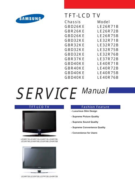
<strong>TFT</strong>-<strong>LCD</strong> <strong>TV</strong><br />
Chassis Model<br />
GBD26KE LE26R71B<br />
GBR26KE LE26R72B<br />
GBD26KE LE26R75B<br />
GBD32KE LE32R71B<br />
GBR32KE LE32R72B<br />
GBD32KE LE32R75B<br />
GBD32KE LE32R76B<br />
GBR37KE LE37R72B<br />
GBD40KE LE40R71B<br />
GBR40KE LE40R72B<br />
GBD40KE LE40R75B<br />
GBD40KE LE40R76B<br />
Manual<br />
<strong>TFT</strong>-<strong>LCD</strong> <strong>TV</strong> Fashion Feature<br />
LE26R71B,LE32R71B,LE40R71B,LE26R75B,<br />
LE32R75B,LE40R75B,LE32R76B,LE40R76B<br />
LE26R72B,LE32R72B,LE37R72B,LE40R72B<br />
- Luxurious Slim Design<br />
- Supreme Picture Quality<br />
- Supreme Sound Quality<br />
- Supreme Convenience Quality<br />
- Convenience for Users
9 Schematic Diagrams<br />
-This Document can not be used without Samsung's authorization.<br />
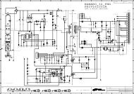
9-1 Power_Sound Schematic Diagram<br />
9 Schematic Diagrams<br />
9-1
9 Schematic Diagrams<br />
-This Document can not be used without Samsung ’ s authorization.<br />
9-2 Schematic Diagram<br />
9-2
3 Alignments and Adjustments<br />
3-1 Service Instruction<br />
3 Alignments and Adjustments<br />
1. Usually, a color <strong>TV</strong>-VCR needs only slight touch-up adjustment upon installation.<br />
Check the basic characteristics such as height, horizontal and vertical sync.<br />
2. Use the specified test equipment or its equivalent.<br />
3. Correct impedance matching is essential.<br />
4. Avoid overload. Excessive signal from a sweep generator might overload the front-end<br />
of the <strong>TV</strong>. When inserting signal markers, do not allow the marker generator to distort<br />
test result.<br />
5. Connect the <strong>TV</strong> only to an AC power source with voltage and frequency as specified on<br />
the backcover nameplate.<br />
6. Do not attempt to connect or disconnect any wire while the <strong>TV</strong> is turned on. Make sure<br />
that the power cord is disconnected before replacing any parts.<br />
7. To protect aganist shock hazard, use an isolation transform.<br />
3-1
3-3 Factory Data<br />
1. Calibration<br />
2. Option Table XXXX XXXX<br />
3. White Balance<br />
4. SVP-FX<br />
5. Option Block<br />
6. S<strong>TV</strong>8257/STA323W<br />
7. YC Delay<br />
8. Adjust<br />
9. I2C Check<br />
10. W/B MOVIE<br />
11. Checksum<br />
12. Reset<br />
13. Spread Spectrum<br />
T-MILMPEU-1006 (Main Micom Ver)<br />
T-MILMPEUS-1002 (Sub Micom Ver)<br />
Month / Day / Year / Hour / Min. / Sec.<br />
1. Calibration<br />
1) AV Calibration<br />
2) D<strong>TV</strong> Calibration<br />
3) PC Calibration<br />
3 Alignments and Adjustments<br />
2. Option Table XXXX XXXX<br />
Inch Option 32" Carrier Mute ON TTX Group Auto<br />
Gamma OFF Language English Auto Power ON<br />
Panel Option AM<strong>LCD</strong>_INT Auto FM ON ---- OFF<br />
2HDMI OFF High Deviation OFF ---- G<br />
Brt.Sensor OFF TTX ON ---- OFF<br />
EnergySave ON TTX List ON Debug OFF<br />
LBE/FBE OFF ACR OFF Ch.Table SUWON<br />
FRC(Micronas) OFF Dynamic CE ON iD<strong>TV</strong>_Cntry UK<br />
FRC(Samsung) OFF Dynamic Dimming ON Dynamic Contrast OFF<br />
LNA OFF Tuner TOP 10<br />
3-3
3 Alignments and Adjustments<br />
3-4
3 Alignments and Adjustments<br />
3-5
3 Alignments and Adjustments<br />
3-4 Service Adjustment<br />
3-4-1 White Balance - Calibration<br />
If picture color is wrong, do calibration first.<br />
Equipment : CA210, Patten : chess pattern<br />
Execute calibration in Factory Mode<br />
Source AV : PAL composite, Component : 1280*720/60Hz<br />
PC : 1024*768/60Hz<br />
3-4-2 White Balance - Adjustment<br />
If picture color is wrong, check White Balance condition.<br />
Equipment : CA210, Patten : Toshiba<br />
Adjust W/B in Factory Mode<br />
Sub brightness and R/G/B Offset controls low light region<br />
Sub contrast and R/G/B Gain controls high light region<br />
Source AV : PAL composite, Component : 1280*720/60Hz<br />
HDMI[DVI] : 1280*720/60Hz<br />
3-6<br />
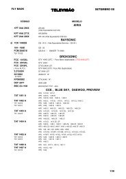
( chess patten )<br />
[ Test Pattern : MSPG-945 Series Pattern #16 ]<br />
*Color temperature<br />
1500K +/-500, -6 ~-20 MPCD<br />
*Color coordinate<br />
H/L : 267/263 +/- 2 35.0 Ft +/- 2.0Ft<br />
L/L : 270/260 +/- 3 1.5 Ft +/- 0.2Ft<br />
Toshiba Patten
3-4-3 Conditions for Measurement<br />
3 Alignments and Adjustments<br />
1. On the basis of toshiba ABL pattern : High Light level (57 IRE)<br />
- INPUT SIGNAL GENERATOR : MSPG-925LTH<br />
* Mode NO 2 : 744X484@60 Hz<br />
NO 6 : 1280X720@60 Hz<br />
NO 21 : 1024X768@60 Hz<br />
* Pattern NO 36 : 16 Color Pattern<br />
NO 16 : Toshiba ABL Pattern<br />
2. Optical measuring device : CA210 (FL)<br />
Please use the MSPG-925 LTH generator for model LE26M51B/LE32M51B/LE40M51B/LE46M51B.<br />
3-4-4 Method of Adjustment<br />
1. Adjust the white balance of AV, Component and DVI Modes.<br />
(AV Component)<br />
a) Set the input to the mode in which the adjustment will be made<br />
(RF D<strong>TV</strong> PC DVI).<br />
* Input signal - VIDEO Mode : Model #2 (744*484 Mode), Pattern #16<br />
- D<strong>TV</strong>,DVI Mode : Model #6 (1280*720 Mode), Pattern #16<br />
- HDMI Mode: Model #6(1280*720 Mode), Pattern #16<br />
b) Enter factory color control, confirm the data.<br />
c) Adjust the low light. (Refer to table 1, 2 in adjustment position by mode)<br />
- Adjust sub - Brightness to set the 'Y' value.<br />
- Adjust red offset ('x') and blue offset ('y') to the color coordinates.<br />
* Do not adjust green offset data.<br />
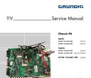
Picture 4-2 Toshiba ABL Pattern<br />
d) Adjust the high light. (Refer to table 1, 2 in adjustment position by mode)<br />
- Adjust red gain ('x') and blue gain ('y') to the color coordinates.<br />
* Do not adjust the green gain and sub-contrast (Y) data.<br />
Low light<br />
Measurement point<br />
3-7
3 Alignments and Adjustments<br />
3-8<br />
d) Adjust the high light. (Refer to table 1, 2 in adjustment position by mode)<br />
- Adjust red gain ('x') and blue gain ('y') to the color coordinates.<br />
* Do not adjust the green gain and sub-contrast (Y) data.<br />
Picture 4-3 Toshiba ABL Pattern<br />
High light<br />
Measurement point
3-5 Software Upgrade<br />
3-5-1 How to Update Flash ROM<br />
1. Installthe Flash Downloader<br />
ConnectSet(Service Jack)and Jig Cable to execute Program Update.<br />
2. Flash Downloader program update<br />
-Before Turning on the set,Click "connect"which is under of OSD Screen!<br />
-Turn on the Set.<br />
3 Alignments and Adjustments<br />
3-9
3 Alignments and Adjustments<br />
Memo<br />
3-10
-This Document can not be used without Samsung ’ s authorization.<br />
9-3 Micom Schematic Diagram<br />
9 Schematic Diagrams<br />
9-3
9 Schematic Diagrams<br />
-This Document can not be used without Samsung ’ s authorization.<br />
9-4 SVP-PX/PX-Power/LBE-Option Schematic Diagram<br />
9-4
-This Document can not be used without Samsung ’ s authorization.<br />
9-5 Application Schematic Diagram<br />
9 Schematic Diagrams<br />
9-5