LCD TV SERVICE MANUAL - Goldhand
LCD TV SERVICE MANUAL - Goldhand
LCD TV SERVICE MANUAL - Goldhand

You also want an ePaper? Increase the reach of your titles
YUMPU automatically turns print PDFs into web optimized ePapers that Google loves.
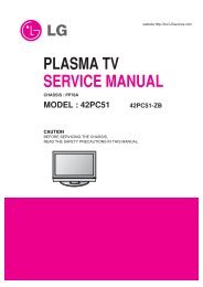
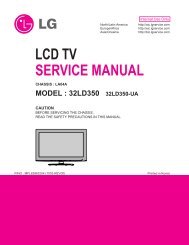
<strong>LCD</strong> <strong>TV</strong><br />
<strong>SERVICE</strong> <strong>MANUAL</strong><br />
CHASSIS : LD84A<br />
MODEL : 32LG3000 32LG3000-ZA<br />
CAUTION<br />
BEFORE SERVICING THE CHASSIS,<br />
READ THE SAFETY PRECAUTIONS IN THIS <strong>MANUAL</strong>.<br />
Internal Use Only<br />
website:http://biz.LGservice.com
Copyright © 2008 LG Electronics. Inc. All right reserved.<br />
Only for training and service purposes<br />
CONTENTS<br />
CONTENTS .............................................................................................. 2<br />
PRODUCT SAFETY ..................................................................................3<br />
SPECIFICATION ........................................................................................6<br />
ADJUSTMENT INSTRUCTION ...............................................................10<br />
TROUBLE SHOOTING ............................................................................14<br />
BLOCK DIAGRAM...................................................................................20<br />
EXPLODED VIEW .................................................................................. 22<br />
SVC. SHEET ...............................................................................................<br />
- 2 -<br />
LGE Internal Use Only
Copyright © 2008 LG Electronics. Inc. All right reserved.<br />
Only for training and service purposes<br />
SAFETY PRECAUTIONS<br />
Many electrical and mechanical parts in this chassis have special safety-related characteristics. These parts are identified by in the<br />
Schematic Diagram and Replacement Parts List.<br />
It is essential that these special safety parts should be replaced with the same components as recommended in this manual to prevent<br />
Shock, Fire, or other Hazards.<br />
Do not modify the original design without permission of manufacturer.<br />
General Guidance<br />
An isolation Transformer should always be used during the<br />
servicing of a receiver whose chassis is not isolated from the AC<br />
power line. Use a transformer of adequate power rating as this<br />
protects the technician from accidents resulting in personal injury<br />
from electrical shocks.<br />
It will also protect the receiver and it's components from being<br />
damaged by accidental shorts of the circuitry that may be<br />
inadvertently introduced during the service operation.<br />
If any fuse (or Fusible Resistor) in this <strong>TV</strong> receiver is blown,<br />
replace it with the specified.<br />
When replacing a high wattage resistor (Oxide Metal Film Resistor,<br />
over 1W), keep the resistor 10mm away from PCB.<br />
Keep wires away from high voltage or high temperature parts.<br />
Before returning the receiver to the customer,<br />
always perform an AC leakage current check on the exposed<br />
metallic parts of the cabinet, such as antennas, terminals, etc., to<br />
be sure the set is safe to operate without damage of electrical<br />
shock.<br />
Leakage Current Cold Check(Antenna Cold Check)<br />
With the instrument AC plug removed from AC source, connect an<br />
electrical jumper across the two AC plug prongs. Place the AC<br />
switch in the on position, connect one lead of ohm-meter to the AC<br />
plug prongs tied together and touch other ohm-meter lead in turn to<br />
each exposed metallic parts such as antenna terminals, phone<br />
jacks, etc.<br />
If the exposed metallic part has a return path to the chassis, the<br />
measured resistance should be between 1MΩ and 5.2MΩ.<br />
When the exposed metal has no return path to the chassis the<br />
reading must be infinite.<br />
An other abnormality exists that must be corrected before the<br />
receiver is returned to the customer.<br />
IMPORTANT SAFETY NOTICE<br />
- 3 -<br />
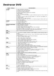
Leakage Current Hot Check (See below Figure)<br />
Plug the AC cord directly into the AC outlet.<br />
Do not use a line Isolation Transformer during this check.<br />
Connect 1.5K/10watt resistor in parallel with a 0.15uF capacitor<br />
between a known good earth ground (Water Pipe, Conduit, etc.)<br />
and the exposed metallic parts.<br />
Measure the AC voltage across the resistor using AC voltmeter<br />
with 1000 ohms/volt or more sensitivity.<br />
Reverse plug the AC cord into the AC outlet and repeat AC voltage<br />
measurements for each exposed metallic part. Any voltage<br />
measured must not exceed 0.75 volt RMS which is corresponds to<br />
0.5mA.<br />
In case any measurement is out of the limits specified, there is<br />
possibility of shock hazard and the set must be checked and<br />
repaired before it is returned to the customer.<br />
Leakage Current Hot Check circuit<br />
To Instrument's<br />
exposed<br />
METALLIC PARTS<br />
AC Volt-meter<br />
0.15uF<br />
1.5 Kohm/10W<br />
Good Earth Ground<br />
such as WATER PIPE,<br />
CONDUIT etc.<br />
LGE Internal Use Only
CAUTION: Before servicing receivers covered by this service<br />
manual and its supplements and addenda, read and follow the<br />
SAFETY PRECAUTIONS on page 3 of this publication.<br />
NOTE: If unforeseen circumstances create conflict between the<br />
following servicing precautions and any of the safety precautions on<br />
page 3 of this publication, always follow the safety precautions.<br />
Remember: Safety First.<br />
General Servicing Precautions<br />
1. Always unplug the receiver AC power cord from the AC power<br />
source before;<br />
a. Removing or reinstalling any component, circuit board<br />
module or any other receiver assembly.<br />
b. Disconnecting or reconnecting any receiver electrical plug or<br />
other electrical connection.<br />
c. Connecting a test substitute in parallel with an electrolytic<br />
capacitor in the receiver.<br />
CAUTION: A wrong part substitution or incorrect polarity<br />
installation of electrolytic capacitors may result in an<br />
explosion hazard.<br />
2. Test high voltage only by measuring it with an appropriate high<br />
voltage meter or other voltage measuring device (DVM,<br />
FE<strong>TV</strong>OM, etc) equipped with a suitable high voltage probe.<br />
Do not test high voltage by "drawing an arc".<br />
3. Do not spray chemicals on or near this receiver or any of its<br />
assemblies.<br />
4. Unless specified otherwise in this service manual, clean<br />
electrical contacts only by applying the following mixture to the<br />
contacts with a pipe cleaner, cotton-tipped stick or comparable<br />
non-abrasive applicator; 10% (by volume) Acetone and 90% (by<br />
volume) isopropyl alcohol (90%-99% strength)<br />
CAUTION: This is a flammable mixture.<br />
Unless specified otherwise in this service manual, lubrication of<br />
contacts in not required.<br />
5. Do not defeat any plug/socket B+ voltage interlocks with which<br />
receivers covered by this service manual might be equipped.<br />
6. Do not apply AC power to this instrument and/or any of its<br />
electrical assemblies unless all solid-state device heat sinks are<br />
correctly installed.<br />
7. Always connect the test receiver ground lead to the receiver<br />
chassis ground before connecting the test receiver positive<br />
lead.<br />
Always remove the test receiver ground lead last.<br />
8. Use with this receiver only the test fixtures specified in this<br />
service manual.<br />
CAUTION: Do not connect the test fixture ground strap to any<br />
heat sink in this receiver.<br />
Electrostatically Sensitive (ES) Devices<br />
Some semiconductor (solid-state) devices can be damaged easily<br />
by static electricity. Such components commonly are called<br />
Electrostatically Sensitive (ES) Devices. Examples of typical ES<br />
devices are integrated circuits and some field-effect transistors and<br />
semiconductor "chip" components. The following techniques<br />
should be used to help reduce the incidence of component<br />
damage caused by static by static electricity.<br />
1. Immediately before handling any semiconductor component or<br />
semiconductor-equipped assembly, drain off any electrostatic<br />
charge on your body by touching a known earth ground.<br />
Alternatively, obtain and wear a commercially available<br />
discharging wrist strap device, which should be removed to<br />
prevent potential shock reasons prior to applying power to the<br />
Copyright © 2008 LG Electronics. Inc. All right reserved.<br />
Only for training and service purposes<br />
SERVICING PRECAUTIONS<br />
- 4 -<br />
unit under test.<br />
2. After removing an electrical assembly equipped with ES<br />
devices, place the assembly on a conductive surface such as<br />
aluminum foil, to prevent electrostatic charge buildup or<br />
exposure of the assembly.<br />
3. Use only a grounded-tip soldering iron to solder or unsolder ES<br />
devices.<br />
4. Use only an anti-static type solder removal device. Some solder<br />
removal devices not classified as "anti-static" can generate<br />
electrical charges sufficient to damage ES devices.<br />
5. Do not use freon-propelled chemicals. These can generate<br />
electrical charges sufficient to damage ES devices.<br />
6. Do not remove a replacement ES device from its protective<br />
package until immediately before you are ready to install it.<br />
(Most replacement ES devices are packaged with leads<br />
electrically shorted together by conductive foam, aluminum foil<br />
or comparable conductive material).<br />
7. Immediately before removing the protective material from the<br />
leads of a replacement ES device, touch the protective material<br />
to the chassis or circuit assembly into which the device will be<br />
installed.<br />
CAUTION: Be sure no power is applied to the chassis or circuit,<br />
and observe all other safety precautions.<br />
8. Minimize bodily motions when handling unpackaged<br />
replacement ES devices. (Otherwise harmless motion such as<br />
the brushing together of your clothes fabric or the lifting of your<br />
foot from a carpeted floor can generate static electricity<br />
sufficient to damage an ES device.)<br />
General Soldering Guidelines<br />
1. Use a grounded-tip, low-wattage soldering iron and appropriate<br />
tip size and shape that will maintain tip temperature within the<br />
range or 500°F to 600°F.<br />
2. Use an appropriate gauge of RMA resin-core solder composed<br />
of 60 parts tin/40 parts lead.<br />
3. Keep the soldering iron tip clean and well tinned.<br />
4. Thoroughly clean the surfaces to be soldered. Use a mall wirebristle<br />
(0.5 inch, or 1.25cm) brush with a metal handle.<br />
Do not use freon-propelled spray-on cleaners.<br />
5. Use the following unsoldering technique<br />
a. Allow the soldering iron tip to reach normal temperature.<br />
(500°F to 600°F)<br />
b. Heat the component lead until the solder melts.<br />
c. Quickly draw the melted solder with an anti-static, suctiontype<br />
solder removal device or with solder braid.<br />
CAUTION: Work quickly to avoid overheating the circuit<br />
board printed foil.<br />
6. Use the following soldering technique.<br />
a. Allow the soldering iron tip to reach a normal temperature<br />
(500°F to 600°F)<br />
b. First, hold the soldering iron tip and solder the strand against<br />
the component lead until the solder melts.<br />
c. Quickly move the soldering iron tip to the junction of the<br />
component lead and the printed circuit foil, and hold it there<br />
only until the solder flows onto and around both the<br />
component lead and the foil.<br />
CAUTION: Work quickly to avoid overheating the circuit<br />
board printed foil.<br />
d. Closely inspect the solder area and remove any excess or<br />
splashed solder with a small wire-bristle brush.<br />
LGE Internal Use Only
IC Remove/Replacement<br />
Some chassis circuit boards have slotted holes (oblong) through<br />
which the IC leads are inserted and then bent flat against the<br />
circuit foil. When holes are the slotted type, the following technique<br />
should be used to remove and replace the IC. When working with<br />
boards using the familiar round hole, use the standard technique<br />
as outlined in paragraphs 5 and 6 above.<br />
Removal<br />
1. Desolder and straighten each IC lead in one operation by gently<br />
prying up on the lead with the soldering iron tip as the solder<br />
melts.<br />
2. Draw away the melted solder with an anti-static suction-type<br />
solder removal device (or with solder braid) before removing the<br />
IC.<br />
Replacement<br />
1. Carefully insert the replacement IC in the circuit board.<br />
2. Carefully bend each IC lead against the circuit foil pad and<br />
solder it.<br />
3. Clean the soldered areas with a small wire-bristle brush.<br />
(It is not necessary to reapply acrylic coating to the areas).<br />
"Small-Signal" Discrete Transistor<br />
Removal/Replacement<br />
1. Remove the defective transistor by clipping its leads as close as<br />
possible to the component body.<br />
2. Bend into a "U" shape the end of each of three leads remaining<br />
on the circuit board.<br />
3. Bend into a "U" shape the replacement transistor leads.<br />
4. Connect the replacement transistor leads to the corresponding<br />
leads extending from the circuit board and crimp the "U" with<br />
long nose pliers to insure metal to metal contact then solder<br />
each connection.<br />
Power Output, Transistor Device<br />
Removal/Replacement<br />
1. Heat and remove all solder from around the transistor leads.<br />
2. Remove the heat sink mounting screw (if so equipped).<br />
3. Carefully remove the transistor from the heat sink of the circuit<br />
board.<br />
4. Insert new transistor in the circuit board.<br />
5. Solder each transistor lead, and clip off excess lead.<br />
6. Replace heat sink.<br />
Diode Removal/Replacement<br />
1. Remove defective diode by clipping its leads as close as<br />
possible to diode body.<br />
2. Bend the two remaining leads perpendicular y to the circuit<br />
board.<br />
3. Observing diode polarity, wrap each lead of the new diode<br />
around the corresponding lead on the circuit board.<br />
4. Securely crimp each connection and solder it.<br />
5. Inspect (on the circuit board copper side) the solder joints of<br />
the two "original" leads. If they are not shiny, reheat them and if<br />
necessary, apply additional solder.<br />
Fuse and Conventional Resistor<br />
Removal/Replacement<br />
1. Clip each fuse or resistor lead at top of the circuit board hollow<br />
stake.<br />
2. Securely crimp the leads of replacement component around<br />
notch at stake top.<br />
3. Solder the connections.<br />
CAUTION: Maintain original spacing between the replaced<br />
component and adjacent components and the circuit board to<br />
prevent excessive component temperatures.<br />
Copyright © 2008 LG Electronics. Inc. All right reserved.<br />
Only for training and service purposes<br />
- 5 -<br />
Circuit Board Foil Repair<br />
Excessive heat applied to the copper foil of any printed circuit<br />
board will weaken the adhesive that bonds the foil to the circuit<br />
board causing the foil to separate from or "lift-off" the board. The<br />
following guidelines and procedures should be followed whenever<br />
this condition is encountered.<br />
At IC Connections<br />
To repair a defective copper pattern at IC connections use the<br />
following procedure to install a jumper wire on the copper pattern<br />
side of the circuit board. (Use this technique only on IC<br />
connections).<br />
1. Carefully remove the damaged copper pattern with a sharp<br />
knife. (Remove only as much copper as absolutely necessary).<br />
2. carefully scratch away the solder resist and acrylic coating (if<br />
used) from the end of the remaining copper pattern.<br />
3. Bend a small "U" in one end of a small gauge jumper wire and<br />
carefully crimp it around the IC pin. Solder the IC connection.<br />
4. Route the jumper wire along the path of the out-away copper<br />
pattern and let it overlap the previously scraped end of the good<br />
copper pattern. Solder the overlapped area and clip off any<br />
excess jumper wire.<br />
At Other Connections<br />
Use the following technique to repair the defective copper pattern<br />
at connections other than IC Pins. This technique involves the<br />
installation of a jumper wire on the component side of the circuit<br />
board.<br />
1. Remove the defective copper pattern with a sharp knife.<br />
Remove at least 1/4 inch of copper, to ensure that a hazardous<br />
condition will not exist if the jumper wire opens.<br />
2. Trace along the copper pattern from both sides of the pattern<br />
break and locate the nearest component that is directly<br />
connected to the affected copper pattern.<br />
3. Connect insulated 20-gauge jumper wire from the lead of the<br />
nearest component on one side of the pattern break to the lead<br />
of the nearest component on the other side.<br />
Carefully crimp and solder the connections.<br />
CAUTION: Be sure the insulated jumper wire is dressed so the<br />
it does not touch components or sharp edges.<br />
LGE Internal Use Only
SPECIFICATION<br />
NOTE : Specifications and others are subject to change without notice for improvement.<br />
1. Application range<br />
This specification is applied to the <strong>LCD</strong> <strong>TV</strong> used LD84A<br />
chassis.<br />
2. Requirement for Test<br />
Each part is tested as below without special appointment.<br />
1) Temperature : 25±5ºC (77±9ºF), CST : 40±5ºC<br />
2) Relative Humidity : 65±10%<br />
3) Power Voltage : Standard input voltage(100-240V~, 50/60Hz)<br />
* Standard Voltage of each products is marked by models.<br />
4) Specification and performance of each parts are followed<br />
each drawing and specification by part number in<br />
accordance with BOM.<br />
5) The receiver must be operated for about 20 minutes prior to<br />
the adjustment.<br />
4. Module general specification<br />
Item Specification Remark<br />
Display Screen Device 32” wide Color Display Module <strong>LCD</strong><br />
Aspect Ratio 16:9<br />
<strong>LCD</strong> Module 32.0” TFT <strong>LCD</strong> HD LG3000<br />
MAKER : 32”- CMO<br />
Operating Environment Temp. : 0 ~ 40 deg<br />
Humidity : 0 ~ 85%<br />
LGE SPEC<br />
Storage Environment Temp. : -20 ~ 60 deg<br />
Humidity : 0 ~ 85 %<br />
Input Voltage 100 - 240V~, 50/60Hz<br />
Power Consumption Power on (Green) LG3000<br />
32” Type:110, Max:120 <strong>LCD</strong> + Backlight<br />
Type Size 32” 760(H) x 450(V) x 47.4(D) LG3000<br />
With inverter<br />
Pixel Pitch 32” 0.17025(H) x 0.51075 (V) LG3000<br />
Back Light 32” 16CCFL, Straight type LG3000<br />
Display Colors 16.7M (16,777,216)<br />
Coating 3H, AG<br />
Copyright © 2008 LG Electronics. Inc. All right reserved.<br />
Only for training and service purposes<br />
- 6 -<br />
3. Test method<br />
1) Performance: LGE <strong>TV</strong> test method followed<br />
2) Demanded other specification<br />
- Safety: CE, IEC specification<br />
- EMC: CE, IEC<br />
Model Market Appliance<br />
32LG3000-ZA EU(PAL market) Safety : IEC/EN60065<br />
EMI : EN55013<br />
EMS : EN55020<br />
LGE Internal Use Only
5. Model general specification<br />
Item Specification Remark<br />
Market EU (PAL Market-26 Countries) D<strong>TV</strong> & Analog<br />
UK, France, Germany, Spain, Sweden, Finland, Italy,<br />
Netherland, Belgium, Luxemburg, Greece, Denmark,<br />
Czech, Austria, Hngary, Switzerland, Croatia, Turkey<br />
Analog Only<br />
Poland, Portugal, Norway, Bulgaria, Serbia, Slovenia,<br />
Russia, Romania<br />
Broadcasting system PAL-BG<br />
PAL-DK<br />
PAL-I/I’<br />
SECAM L/L’<br />
DVB-T(ID <strong>TV</strong>)<br />
Receiving system Analog : Upper Heterodyne<br />
Digital : COFDM<br />
Scart Jack (2EA) PAL, SECAM Scart 1 Jack is Full scart and support RF-OUT(analog).<br />
Scart 2 Jack is Half scart and support MNT/D<strong>TV</strong>-OUT.<br />
Video Input RCA(1EA) PAL, SECAM, NTSC 4 System : PAL, SECAM, NTSC, PAL60<br />
S-Video Input (1EA) PAL, SECAM, NTSC 4 System : PAL, SECAM, NTSC, PAL60<br />
Component Input(1EA) Y/Cb/Cr<br />
Y/ Pb/Pr<br />
RGB Input(1EA) RGB-PC Analog (D-SUB 15PIN)<br />
HDMI Input(3EA) HDMI1-D<strong>TV</strong>/DVI PC(HDMI version 1.3)<br />
HDMI2-D<strong>TV</strong><br />
HDMI3-D<strong>TV</strong><br />
Support HDCP<br />
Audio Input(3EA) RGB/DVI Audio<br />
Component<br />
AV<br />
L/R Input<br />
SPDIF out(1EA) SPDIF out<br />
Earphone (1EA) Antenna, AV1, AV2, AV3, Component,<br />
RGB, HDMI1, HDMI2, HDMI<br />
USB (1EA) For service only<br />
Copyright © 2008 LG Electronics. Inc. All right reserved.<br />
Only for training and service purposes<br />
- 7 -<br />
LGE Internal Use Only
6. Component Video Input (Y, PB, PR)<br />
No Specification Remark<br />
Resolution H-freq(kHz) V-freq(Hz)<br />
1 720*480 15.73 60.00 SD<strong>TV</strong>, DVD 480i<br />
2 720*480 15.63 59.94 SD<strong>TV</strong>, DVD 480i<br />
3 720*480 31.47 59.94 480p<br />
4 720*480 31.50 60.00 480p<br />
5 720*576 15.625 50.00 SD<strong>TV</strong>, DVD 625 Line<br />
6 720*576 31.25 50.00 HD<strong>TV</strong> 576p<br />
7 1280*720 45.00 50.00 HD<strong>TV</strong> 720p<br />
8 1280*720 44.96 59.94 HD<strong>TV</strong> 720p<br />
9 1280*720 45.00 60.00 HD<strong>TV</strong> 720p<br />
10 1920*1080 31.25 50.00 HD<strong>TV</strong> 1080i<br />
11 1920*1080 33.75 60.00 HD<strong>TV</strong> 1080i<br />
12 1920*1080 33.72 59.94 HD<strong>TV</strong> 1080i<br />
13 1920*1080 26.97/27 23.97/24 HD<strong>TV</strong> 1080p<br />
14 1920*1080 33.716/33.75 29.976/30.00 HD<strong>TV</strong> 1080p<br />
15 1920*1080 56.250 50 HD<strong>TV</strong> 1080p<br />
16 1920*1080 67.43/67.5 59.94/60 HD<strong>TV</strong> 1080p<br />
7. RGB PC INPUT Mode<br />
No Resolution H-freq(kHz) V-freq.(Hz) Pixel clock(MHz) Proposed<br />
1 720*400 31.468 70.08 28.321<br />
2 640*480 31.469 59.94 25.17 VESA Input 848*480 60Hz, 852*480 60Hz<br />
37.684 75.00 31.50 -> 640*480 60Hz Display<br />
3 800*600 37.879 60.31 40.00 VESA<br />
46.875 75.00 49.50<br />
4 832*624 49.725 74.55 57.283 Macintosh<br />
5 1024*768 48.363 60.00 65.00 VESA(XGA)<br />
56.470 70.00 75.00<br />
60.123 75.029 78.75<br />
6 1280*768 47.78 59.87 79.5 WXGA<br />
7 1360*768 47.72 59.8 84.75 WXGA<br />
8 1366*768 47.56 59.6 84.75 WXGA<br />
9 1440*900 55.5 59.90 88.750 WXGA 19LG3000-ZA only<br />
10 1400*1050 64.744 59.948 101.00 WSXGA 22LG3000-ZA only<br />
11 1680*1050 65.16 59.94 147.00 WSXGA 22LG3000-ZA only<br />
12 1280*1024 63.595 60.0 108.875 SXGA FHD Model only<br />
13 1920*1080 66.647 59.988 138.625 WUXGA FHD Model only<br />
Copyright © 2008 LG Electronics. Inc. All right reserved.<br />
Only for training and service purposes<br />
- 8 -<br />
LGE Internal Use Only
8. HDMI D<strong>TV</strong><br />
No Resolution H-freq(kHz) V-freq.(Hz) Pixel clock(MHz) Proposed<br />
1 720*480 15.734 / 15.6 59.94 / 60 27.00 SD<strong>TV</strong> 480I<br />
2 720*480 31.469 / 31.5 59.94 / 60 27.00/27.03 SD<strong>TV</strong> 480P<br />
3 720*576 15.625 50 27(54) SD<strong>TV</strong> 576I<br />
4 720*576 31.25 50 54 SD<strong>TV</strong> 576P<br />
5 1280*720 37.500 50 74.25 HD<strong>TV</strong> 720P<br />
6 1280*720 44.96 / 45 59.94 / 60 74.17/74.25 HD<strong>TV</strong> 720P<br />
7 1920*1080 33.72 / 33.75 59.94 / 60 74.17/74.25 HD<strong>TV</strong> 1080I<br />
8 1920*1080 28.125 50.00 74.25 HD<strong>TV</strong> 1080I<br />
9 1920*1080 26.97 / 27 23.97 / 24 74.17/74.25 HD<strong>TV</strong> 1080P<br />
10 1920*1080 33.716 / 33.75 29.976 / 30.00 74.25 HD<strong>TV</strong> 1080P<br />
11 1920*1080 56.250 50 148.5 HD<strong>TV</strong> 1080P<br />
12 1920*1080 67.43 / 67.5 59.94 / 60 148.35/148.50 HD<strong>TV</strong> 1080P<br />
9. HDMI PC<br />
No Resolution H-freq(kHz) V-freq.(Hz) Pixel clock(MHz) Proposed Remark<br />
1 720*400 31.468 70.08 28.321 HDCP<br />
2 640*480 31.469 59.94 25.17 VESA HDCP<br />
37.684 75.00 31.50<br />
3 800*600 37.879 60.31 40.00 VESA HDCP<br />
46.875 75.00 49.50<br />
4 832*624 49.725 74.55 57.283 Macintosh HDCP<br />
5 1024*768 48.363 60.00 65.00 VESA(XGA) HDCP<br />
56.470 70.00 75.00<br />
60.123 75.029 78.75<br />
6 1280*768 47.78 59.87 79.5 WXGA HDCP<br />
7 1360*768 47.72 59.8 84.75 WXGA HDCP<br />
8 1366*768 47.56 59.6 84.75 WXGA HDCP<br />
9 1440*900 55.5 59.90 88.750 WXGA 19LG3000-ZA only<br />
10 1400*1050 64.744 59.948 101.00 WSXGA 22LG3000-ZA only<br />
11 1680*1050 65.16 59.94 147.00 WSXGA 22LG3000-ZA only<br />
12 1280*1024 63.595 60.0 108.875 SXGA FHD Model only, HDCP<br />
13 1920*1080 66.647 59.988 138.625 WUXGA FHD Model only, HDCP<br />
Copyright © 2008 LG Electronics. Inc. All right reserved.<br />
Only for training and service purposes<br />
- 9 -<br />
LGE Internal Use Only
1. Application Range<br />
This specification sheet is applied to all of the <strong>LCD</strong> <strong>TV</strong> with<br />
LD84A chassis.<br />
2. Designation<br />
1) The adjustment is according to the order which is<br />
designated and which must be followed, according to the<br />
plan which can be changed only on agreeing.<br />
2) Power Adjustment: Free Voltage<br />
3) Magnetic Field Condition: Nil.<br />
4) Input signal Unit: Product Specification Standard<br />
5) Reserve after operation: Above 5 Minutes (Heat Run)<br />
Temperature : at 25±5ºC<br />
Relative humidity : 65±10%<br />
Input voltage : 220V, 60Hz<br />
6) Adjustment equipments: Color Analyzer (CA-210 or CA-<br />
110), Pattern Generator (MSPG-925L or Equivalent), DDC<br />
Adjustment Jig equipment, SVC remote controller<br />
7) Don’t push The “IN STOP KEY” after completing the<br />
function inspection.<br />
3. Main PCB check process<br />
* APC - After Manual-Insult, executing APC<br />
* Download<br />
1) Execute ISP program “Mstar ISP Utility” and then click<br />
“Config” tab.<br />
2) Set as below, and then click “Auto Detect” and check “OK”<br />
message. If display “Error”, Check connect computer, jig,<br />
and set.<br />
3) Click “Connect” tab. If display “Can’t”, Check connect<br />
computer, jig, and set.<br />
(2) OK<br />
4) Click “Read” tab, and then load download file(XXXX.bin) by<br />
clicking “Read”.<br />
(4)<br />
filexxx.bin<br />
(1) (3)<br />
Copyright © 2008 LG Electronics. Inc. All right reserved.<br />
Only for training and service purposes<br />
ADJUSTMENT INSTRUCTION<br />
Please Check Speed :<br />
To us speed between from 200 KHz<br />
to 400 KHz<br />
- 10 -<br />
5. Click “Auto” tab and set as below<br />
6. Click “Run”.<br />
7. After downloading, check “OK” message.<br />
(5)<br />
filexxx.bin<br />
* USB DOWNLOAD<br />
1) Put the USB Stick to the USB socket<br />
2) Automatically detecting update file in USB Stick<br />
- If your downloaded program version in USB Stick is Low,<br />
it didn’t work. But your downloaded version is High, USB<br />
data is automatically detecting<br />
3) Show the message “Copying files from memory”<br />
4) Updating is staring.<br />
(6)<br />
(7) ........ OK<br />
5) Updating Completed, The <strong>TV</strong> will restart automatically.<br />
6) If your <strong>TV</strong> is turned on, check your updated version and<br />
Tool option. (explain the Tool option, next stage)<br />
* If downloading version is more high than your <strong>TV</strong> have,<br />
<strong>TV</strong> can lost all channel data. In this case, you have to<br />
channel recover. if all channel data is cleared, you didn’t<br />
have a D<strong>TV</strong>/A<strong>TV</strong> test on production line.<br />
LGE Internal Use Only
* After downloading, have to adjust TOOL OPTION again.<br />
1) Push "IN-START" key in service remote controller<br />
2) Select "Tool Option 1" and Punch in the number.(Each<br />
model has their number.)<br />
32LG5000-ZA : 8977<br />
3) Completed selecting Tool option<br />
3.1. ADC Process<br />
(1) PC input ADC<br />
1) Auto RGB Gain/Offset Adjustment<br />
- Convert to PC in Input-source<br />
- Signal equipment displays<br />
Output Voltage : 700 mVp-p<br />
Impress Resolution XGA (1024 x 768 @ 60Hz)<br />
Model : 60 in Pattern Generator<br />
Pattern : 65 in Pattern Generator (MSPG-925 Series)<br />
Adjustment pattern(PC)<br />
- Adjust by commanding AUTO_COLOR_ADJUST.<br />
2) Confirmation<br />
- We confirm whether “0xAA (RGB)” address of<br />
EEPROM “0xA2” is “0xAA” or not.<br />
- If “0xAA (RGB)” address of EEPROM “0xA2” isn’t<br />
“0xAA”, we adjust once more<br />
- We can confirm the ADC values from “0xA4~0XA9<br />
(RGB)” addresses in a page “0xA2”<br />
* Manual ADC process using Service Remocon. After<br />
enter Service Mode by pushing “ADJ” key,<br />
execute “ADC Adjust” by pushing “G” key at “ADC<br />
CALIBRATION: RGB-PC”.<br />
(2) COMPONENT input ADC<br />
1) Component Gain/Offset Adjustment<br />
- Convert to Component in Input-source<br />
- Signal equipment displays<br />
Impress Resolution 480i<br />
MODEL : 209 in Pattern Generator(480i Mode)<br />
Pattern : 65 in Pattern Generator (MSPG-925 series)<br />
Copyright © 2008 LG Electronics. Inc. All right reserved.<br />
Only for training and service purposes<br />
- 11 -<br />
Impress Resolution 1080i<br />
Model : 223 in Pattern Generator(1080i Mode)<br />
Pattern: 65 in Pattern Generator(MSPG-925 series)<br />
Adjustment pattern(COMPONENT)<br />
- Adjust by commanding AUTO_COLOR_ADJUST.<br />
2) Confirmation<br />
- We confirm whether “0xB3 (480i)/0xBC (1080i)”<br />
address of EEPROM “0xA2” is “0xAA” or not.<br />
- If “0xB3 (480i)/0xBC(1080i)” address of EEPROM<br />
“0xA2” isn’t “0xAA”, we adjust once more.<br />
- We can confirm the ADC values from “0xAD~0XB2<br />
(480i)/0XB6~BB (1080i)” addresses in a page “0xA2”.<br />
* Manual ADC process using Service Remocon. After<br />
enter Service Mode by pushing “ADJ” key, execute<br />
“ADC Adjust” by pushing “G” key at “ADC<br />
CALIBRATION :COMPONENT”.<br />
Impress Resolution 480i<br />
Impress Resolution 1080i<br />
3.2. Function Check<br />
(1) Check display and sound<br />
- Check Input and Signal items. (cf. work instructions)<br />
1) <strong>TV</strong><br />
2) AV (SCART1/SCART2/S-VHS/CVBS)<br />
3) COMPONENT (480i)<br />
4) RGB (PC : 1024 x 768 @ 60hz)<br />
5) HDMI<br />
6) PC Audio In<br />
* Display and Sound check is executed by Remote<br />
controller.<br />
LGE Internal Use Only
4. Total Assembly line process<br />
4.1. Adjustment Preparation<br />
(1) W/B Equipment condition<br />
CA210: CH 9, Test signal: Inner pattern (85IRE)<br />
(2) Above 5 minutes H/run in the inner pattern. (“power on”<br />
key of adjust remote control)<br />
(3) 15 Pin D-Sub Jack is connected to the AUTO W/B<br />
EQUIPMENT.<br />
(4) Adjust Process will start by execute I2C Command (Inner<br />
pattern (0xF3, 0xFF).<br />
Color Cool 11,000 ºK X=0.276(±0.002) <br />
Temperature Y=0.283(±0.002) Inner patern<br />
Medium 9,300 ºK X=0.285(±0.002)<br />
Y=0.293(±0.002)<br />
(216gray,85IRE)<br />
Warm 6,500 ºK X=0.313(±0.002)<br />
Y=0.329(±0.002)<br />
(5) Adjust Process will finish by execute I2C Command (Inner<br />
pattern (Inner pattern (0xF3,0x00)).<br />
** Caution **<br />
Color Temperature: COOL, Medium, Warm<br />
One of R Gain/G Gain/ B Gain should be kept on 0xC0, and<br />
adjust other two lower than C0.<br />
(when R/G/B Gain are all C0, it is the FULL Dynamic Range<br />
of Module)<br />
* Manual W/B process using adjusts Remote control.<br />
After enter Service Mode by pushing “ADJ” key,<br />
Enter White Pattern off of service mode, and change off -> on.<br />
Enter “W/B ADJUST” by pushing “G” key at “3.W/B ADJUST”.<br />
* After done all adjustments, Press “In-start” button and<br />
compare Tool option and Area option value with its BOM, if it<br />
is correctly same then unplug the AC cable.<br />
If it is not same, then correct it same with BOM and unplug<br />
AC cable.<br />
For correct it to the model’s module from factory JIG model.<br />
* Don’t push The “IN STOP KEY” after completing the function<br />
inspection.<br />
4.2. DPM operation confirmation<br />
(Only Apply for MNT Model)<br />
Check if Power LED Color and Power Consumption operate<br />
as standard.<br />
- Set Input to RGB and connect D-sub cable to set<br />
- Measurement Condition: (100~240V@ 50/60Hz)<br />
- Confirm DPM operation at the state of screen without Signal<br />
Copyright © 2008 LG Electronics. Inc. All right reserved.<br />
Only for training and service purposes<br />
- 12 -<br />
4.3 DDC EDID Write (RGB 128Byte )<br />
- Connect D-sub Signal Cable to D-Sub Jack.<br />
- Write EDID DATA to EEPROM (24C02) by using DDC2B<br />
protocol.<br />
- Check whether written EDID data is correct or not.<br />
4.4. DDC EDID Write (HDMI 256Byte)<br />
- Connect HDMI Signal Cable to HDMI Jack.<br />
- Write EDID DATA to EEPROM(24C02) by using DDC2B<br />
protocol.<br />
- Check whether written EDID data is correct or not.<br />
4.5 Serial number (RS-232C)<br />
- Press “Power on” key of service remocon. (Baud rate :<br />
115200 bps)<br />
- Connect RS232 Signal Cable to RS-232 Jack.<br />
- Write Serial number by use RS-232.<br />
- Must check the serial number at the Diagnostics of SET UP<br />
menu. (Refer to below).<br />
4.6. EDID DATA<br />
(1) ANALOG DATA 128Byte (2Bi)<br />
(2) DIGITAL DATA(HDMI-1) 256Byte<br />
LGE Internal Use Only
(3) DIGITAL DATA(HDMI-2) 256Byte<br />
(4) DIGITAL DATA(HDMI-3) 256Byte<br />
1) All Data : HEXA Value<br />
2) Changeable Data :<br />
*: Serial No : Controlled / Data:01<br />
**: Month : Controlled / Data:00<br />
***:Year : Controlled<br />
****:Check sum<br />
4.7. HDCP (High-Bandwidth Digital Contents Protection)<br />
SETTING (Scaler : Mstar)<br />
- Connect D-sub Signal Cable to D-Sub Jack<br />
- Input HDCP key with HDCP-key- in-program<br />
- HDCP Key value is stored on EEPROM (AT24C512) which<br />
is 0x80 addresses of 0xA0 page<br />
- AC off/ on and on HDCP button of MSPG925 and confirm<br />
whether picture is displayed or not of using MSPG925<br />
- HDCP Key value is different among the sets.<br />
4.11 Outgoing condition Configuration<br />
When pressing IN-STOP key by SVC remocon, Red LED are<br />
blinked alternatively. And then Automatically turn off. (Must<br />
not AC power OFF during blinking)<br />
Copyright © 2008 LG Electronics. Inc. All right reserved.<br />
Only for training and service purposes<br />
- 13 -<br />
4.12 Internal pressure<br />
Confirm whether is normal or not when between power<br />
board's ac block and GND is impacked on 1.5kV(dc) or<br />
2.2kV(dc) for one second<br />
LGE Internal Use Only
1. No Power<br />
(1) Symptom<br />
1) It is not discharged minutely from the module.<br />
2) Light does not come into the front LED.<br />
(2) Check process<br />
Is inserted a plugged<br />
in power cord?<br />
Yes<br />
Is the Line Filter<br />
and Power Board Cable<br />
connected?<br />
Is the fuse of PSU<br />
normal?<br />
Yes<br />
Is it connected<br />
that PSU and P1100 in<br />
Main B/D?<br />
Yes<br />
Copyright © 2008 LG Electronics. Inc. All right reserved.<br />
Only for training and service purposes<br />
TROUBLESHOOTING<br />
No<br />
No<br />
No<br />
No<br />
After all cables connect is removed to PSU, the AC voltage<br />
marking is authorized on manual.<br />
When ST-BY 5V, +15V are not operated, replace PSU.<br />
- 14 -<br />
Plug in the power cord.<br />
Connect the Cable.<br />
Replace the Fuse.<br />
Connect the Cable P1100.<br />
If there is normal status,<br />
Replace main board.<br />
LGE Internal Use Only
2. No Raster<br />
(1) Symptom<br />
1) No OSD abnd image occur at screen.<br />
2) It maintains the conditioon where the front LED is blue.<br />
(2) Check process<br />
Does minute discharge<br />
at Module?<br />
Yes<br />
Change the IC(IC100).<br />
* Caution<br />
Is the link<br />
cable normal?<br />
Yes<br />
Is the IC801’s<br />
output normal?<br />
Yes<br />
No No<br />
Is the inverter on?<br />
No<br />
No<br />
Before change Main Board,<br />
Check S/W version and White Balance value.<br />
Check the <strong>LCD</strong> Module.<br />
Copyright © 2008 LG Electronics. Inc. All right reserved.<br />
Only for training and service purposes<br />
Reconnect Panel link cable.<br />
(P401 or P406 or P407)<br />
Replace the Main board.<br />
Change Main bord.<br />
- 15 -<br />
Is output the normality<br />
Low/High voltage except<br />
Stand-by 5V?<br />
No<br />
Replace the Power board.<br />
S/W download and set White Balance value.<br />
LGE Internal Use Only
3. Unusual display from <strong>TV</strong>/CA<strong>TV</strong> mode<br />
Is video<br />
output of the Tuner<br />
normal?(CheckTU500<br />
_Pin15)<br />
Yes<br />
Is the LVDS cable<br />
connected well?<br />
Yes<br />
Change the IC(IC100).<br />
No<br />
No<br />
Copyright © 2008 LG Electronics. Inc. All right reserved.<br />
Only for training and service purposes<br />
Is the input<br />
voltage normal?(Check<br />
TU500_Pin4)<br />
No<br />
Check the Power.<br />
Cable inserts well.<br />
BLOCK A<br />
4. Unusual display from D<strong>TV</strong> mode<br />
Is video<br />
output of the tuner<br />
normal?(Check TU500_<br />
pin24~pin34)<br />
Yes<br />
Same as Block A.<br />
No<br />
Is the input<br />
voltage normal?(Check<br />
Pin21,22)<br />
No<br />
Check the Power.<br />
- 16 -<br />
Yes<br />
Yes<br />
Is the<br />
I2C communication<br />
Normal?(Check Pin10,<br />
Pin11)<br />
No<br />
Check the Tuner.<br />
Is the I2C<br />
communication Normal?<br />
(Check Pin18,<br />
Pin19)<br />
No<br />
Check the Tuner.<br />
Yes<br />
Yes<br />
Replace Main board.<br />
Replace Main board.<br />
LGE Internal Use Only
5. Unusual display from AV1/AV2(SCART) mode<br />
- CVBS Input - RGB Input<br />
Is video<br />
input of SCART Jack<br />
normal?(Check JK600,<br />
JK601_Pin20)<br />
Yes<br />
Same as Block A.<br />
No<br />
Check the input source.<br />
If there is normal status,<br />
Replace main board.<br />
6. Unusual display from AV3(SIDE AV) mode<br />
- CVBS Input<br />
Is video input<br />
of RCA Jack normal?<br />
(Check R704)<br />
Yes<br />
Same as Block A.<br />
No<br />
Copyright © 2008 LG Electronics. Inc. All right reserved.<br />
Only for training and service purposes<br />
Check the input source.<br />
If there is normal status,<br />
Replace main board.<br />
7. Unusual display from Component mode<br />
- CVBS Input<br />
Is video input<br />
of the Component Jack<br />
normal?(Check R733,<br />
734,735)<br />
Yes<br />
Same as Block A.<br />
No<br />
Check the input source.<br />
If there is normal status,<br />
Replace main board.<br />
- 17 -<br />
Is video<br />
input of the RGB Jack<br />
normal?(Check JK600<br />
_Pin7,11,15)<br />
Yes<br />
Is waveform<br />
of Switching IC normal?<br />
(Check IC700_Pin11,<br />
12,13)<br />
No<br />
Same as Block A.<br />
No<br />
No<br />
Check the input source.<br />
Check the IC700.<br />
If there is normal status,<br />
Replace main board.<br />
LGE Internal Use Only
8. Unusual display from RGB mode<br />
Is video input<br />
of the RGB jack normal?<br />
(Check JK703_Pin1,<br />
2,3,13,14)<br />
Yes<br />
Is waveform<br />
of Switching IC normal?<br />
(Check IC700_Pin11,<br />
12,13)<br />
No<br />
Same as Block A.<br />
No<br />
No<br />
Check the input source.<br />
Check the IC700.<br />
If there is normal status,<br />
Replace main board.<br />
9. Unusual display from HDMI 1/2/3 mode<br />
Is video<br />
input of the HDMI jack<br />
normal? (Check JK900,<br />
901,902)<br />
Yes<br />
Check DDC<br />
communication<br />
lines(IC900,901,903<br />
_Pin5,6<br />
Yes<br />
Check HDCP<br />
communication lines<br />
(IC902)<br />
Yes<br />
Is waveform<br />
of Switching IC normal?<br />
(Check IC902)<br />
No<br />
Same as Block A.<br />
No<br />
No<br />
No<br />
No<br />
Check the input source.<br />
Copyright © 2008 LG Electronics. Inc. All right reserved.<br />
Only for training and service purposes<br />
Check the IC900, IC901, IC903.<br />
Check the IC902 and DHCP value<br />
Check the IC902.<br />
If there is normal status,<br />
Replace main board.<br />
- 18 -<br />
LGE Internal Use Only
10. No Sound<br />
(1) Symptom<br />
1) LED is blue<br />
2) Screen display but sound is not output.<br />
(2) Check process<br />
All input is no sound?<br />
* Caution<br />
Yes<br />
Only HDMI is<br />
no Sound?<br />
Yes<br />
Only RF or D<strong>TV</strong><br />
is no sound?<br />
No<br />
No<br />
Before change Main Board,<br />
Check S/W version and White Balance value.<br />
No<br />
Download the EDID data.<br />
Check the Tuner in/Out.<br />
Copyright © 2008 LG Electronics. Inc. All right reserved.<br />
Only for training and service purposes<br />
- 19 -<br />
Is the speaker<br />
“on” on menu?<br />
Yes<br />
Is the Speaker<br />
cable normal?<br />
Yes<br />
IC100 operate<br />
normally?<br />
Yes<br />
IC1000 operate<br />
normally?<br />
Yes<br />
Replace main board.<br />
No<br />
No<br />
No<br />
No<br />
Set on speaker on menu.<br />
Check th Speaker cable.<br />
Replace IC100.<br />
Replace IC1000.<br />
Change Main bord. S/W download and set White Balance value.<br />
LGE Internal Use Only
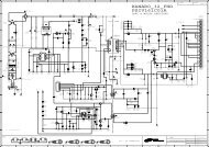
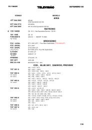
24C512<br />
(IC105)<br />
KIA7427<br />
(IC104)<br />
SC2_L/R_IN<br />
D<strong>TV</strong>/MNT_L/R_OUT<br />
RESET I2C<br />
I/O Expander<br />
(IC103)<br />
STMAV340<br />
(IC700)<br />
Copyright © 2008 LG Electronics. Inc. All right reserved.<br />
Only for training and service purposes<br />
I2C_A_TU<br />
R/G/B<br />
D<strong>TV</strong>/MNT_V_OUT<br />
SC2_CVBS_IN<br />
SC1_CVBS_IN<br />
<strong>TV</strong>_L/R_OUT<br />
SC1_L/R_IN<br />
SC1_R/G/B<br />
SC1_<strong>TV</strong>_VOUT<br />
Flash Memory<br />
4MB (IC102)<br />
EEPROM<br />
DSUB_R/G/B<br />
<strong>LCD</strong> Panel<br />
DDC/UART-Tx/Rx<br />
Flash Memory<br />
4MB (IC101)<br />
BLOCK DIAGRAM<br />
DSUB_H/V_SYNC<br />
DDR Memory<br />
DDR Memory<br />
256Mb (IC300)<br />
256Mb (IC300)<br />
Saturn3+<br />
PC_L/R_IN<br />
52/47/42/37” : FHD<br />
32”: : HD<br />
5V_ANT_MNT<br />
BOOSTER<br />
<strong>TV</strong>_CVBS<br />
SIF<br />
<strong>TV</strong> Tuner<br />
LVDS<br />
TU_TS_DATA<br />
- 20 -<br />
LED_G/R & IR<br />
I2C_D_TU / I2C_A_TU<br />
KEY1/2<br />
COMP_Y/Pb/Pr<br />
IIC(Eye Q II)<br />
PCM_CD_ON<br />
TS_Parallel<br />
PCM_ADD<br />
PCM_DATA<br />
74HC4066<br />
(IC1001)<br />
COMP_L/R_IN<br />
TS_Serial<br />
TPA6110A2<br />
(IC1002)<br />
USB_DM/DP<br />
74LVC541A<br />
(IC800)<br />
CI Slot<br />
(P800)<br />
MAX3232<br />
(IC702)<br />
EEPROM<br />
EEPROM<br />
EEPROM<br />
SP (L)<br />
MUTE<br />
HDMI_I2C<br />
HDMI_CEC/Rx/HPD<br />
NTP3000A<br />
(IC1000)<br />
CI_CD_1/2<br />
SPDIF Out<br />
Head phone Out<br />
Side_Y/C/V/L/R<br />
HDMI<br />
Switch<br />
(IC902)<br />
HDMI_I2C_0<br />
HDMI_CEC x3<br />
IIS<br />
TMDS x3<br />
HPD x3<br />
SP (R)<br />
P1000<br />
KIC7SZ32FU<br />
(IC802)<br />
5V_HDMI<br />
LGE Internal Use Only
Copyright © 2008 LG Electronics. Inc. All right reserved.<br />
Only for training and service purposes<br />
MEMO<br />
- 21 -<br />
LGE Internal Use Only
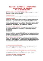
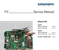
800<br />
300<br />
400<br />
200<br />
804<br />
521<br />
530<br />
803<br />
540<br />
510<br />
Copyright © 2008 LG Electronics. Inc. All right reserved.<br />
Only for training and service purposes<br />
EXPLODED VIEW<br />
121<br />
821<br />
802<br />
- 22 -<br />
550<br />
805<br />
801<br />
500<br />
401<br />
910<br />
120<br />
904<br />
122<br />
830<br />
902 901<br />
905<br />
900<br />
903<br />
LGE Internal Use Only
Copyright © 2008 LG Electronics. Inc. All right reserved.<br />
Only for training and service purposes<br />
LGE Internal Use Only
Copyright © 2008 LG Electronics. Inc. All right reserved.<br />
Only for training and service purposes<br />
LGE Internal Use Only
Copyright © 2008 LG Electronics. Inc. All right reserved.<br />
Only for training and service purposes<br />
LGE Internal Use Only
P/NO : MFL41037107<br />
Feb., 2008<br />
Printed in Korea