KNX Energiezähler, REG-K/3x230 V/ 16 A English operating ...
KNX Energiezähler, REG-K/3x230 V/ 16 A English operating ...
KNX Energiezähler, REG-K/3x230 V/ 16 A English operating ...

Create successful ePaper yourself
Turn your PDF publications into a flip-book with our unique Google optimized e-Paper software.
<strong>KNX</strong> <strong>Energiezähler</strong>, <strong>REG</strong>-K/<strong>3x230</strong> V/<strong>16</strong> AMEG6600-0603© Merten 2009S1B45115-0002/12<br />
de<br />
<strong>KNX</strong> <strong>Energiezähler</strong>, <strong>REG</strong>-K/<strong>3x230</strong> V/<br />
<strong>16</strong> A<br />
Gebrauchsanleitung<br />
1 2 3<br />
Art.-Nr. MEG6600-0603<br />
<strong>English</strong> <strong>operating</strong> instructions<br />
| You will find the <strong>English</strong> version of these opera-<br />
en<br />
N N 1 1 2 2 3 3<br />
ting instructions at: www.merten.com<br />
Zu Ihrer Sicherheit<br />
¼ GEFAHR<br />
Gefahr von schweren Sach- und Personenschäden,<br />
z. B. durch Brand oder elektrischen<br />
Schlag, aufgrund einer unsachgemäßen<br />
Elektroinstallation.<br />
Eine sichere Elektroinstallation kann nur gewährleistet<br />
werden, wenn die handelnde Person nachweislich<br />
über Grundkenntnisse auf folgenden<br />
Gebieten verfügt:<br />
• Anschluss an Installationsnetze<br />
• Verbindung mehrerer Elektrogeräte<br />
• Verlegung von Elektroleitungen<br />
• Anschluss und Errichtung von <strong>KNX</strong>-Netzwerken<br />
Über diese Kenntnisse und Erfahrungen verfügen<br />
in der Regel nur ausgebildete Fachkräfte im<br />
Bereich der Elektro-Installationstechnik. Bei<br />
Nichterfüllung dieser Mindestanforderungen<br />
oder Missachtung droht für Sie die persönliche<br />
Haftung bei Sach- und Personenschäden.<br />
<strong>Energiezähler</strong> kennen lernen<br />
Der <strong>KNX</strong> <strong>Energiezähler</strong>, <strong>REG</strong>-K/<strong>3x230</strong> V/<strong>16</strong> A (im Folgenden<br />
<strong>Energiezähler</strong> genannt) ermöglicht die Energieüberwachung<br />
und -messung der angeschlossenen<br />
Kanäle.<br />
Geräteeigenschaften<br />
• Messung von: Leistung und Strom und Bereitstellung<br />
der Ergebnisse über den <strong>KNX</strong> Bus.<br />
• Ermittlung des Wirkenergieverbrauchs pro Kanal sowie<br />
des Gesamtenergieverbrauchs.<br />
• Genauigkeit des Wirkenergieverbrauchs pro Kanal:<br />
max. 1,5 %<br />
• Genauigkeit der Leistungs- und Strommessung<br />
(kalkuliert): 10 %<br />
• Die ETS ermöglicht folgende Funktionen:<br />
- Energiesparfunktionen (Schalten, Dimmen, Szene,<br />
etc.)<br />
- Alarmfunktionen (Alarm oberhalb/unterhalb des Limits)<br />
• Für die Montage auf einer Hutschienen TH35 nach<br />
DIN EN 60715.<br />
• Der Busanschluss erfolgt über eine Busanschlussklemme.<br />
| Benutzen Sie das Gerät niemals in Verbindung<br />
mit Stromwandlern.<br />
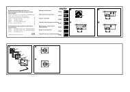
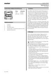
Anschlüsse, Anzeigen und<br />
Bedienelemente<br />
1 2 3<br />
A<br />
N N 1 1 2 2 3 3<br />
F<br />
A Anschluss: Bus<br />
B Schutzkappe für A<br />
C Taste und LED: Programmierung<br />
D LED: RUN<br />
E LED: Kanal 1-3<br />
F Anschlussklemmen<br />
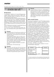
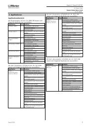
<strong>Energiezähler</strong> montieren<br />
¼ WARNUNG<br />
Lebensgefahr durch elektrischen Schlag.<br />
Das Gerät kann beschädigt werden.<br />
Der Sicherheitsabstand nach IEC 60664-1 muss<br />
gewährleistet sein. Halten Sie zwischen den Einzeladern<br />
der 230 V-Leitung und der <strong>KNX</strong>-Leitung<br />
A einen Abstand von mindestens 4 mm ein.<br />
230 V<br />
4 mm<br />
1 Gerät in die Hutschiene einsetzen.<br />
1<br />
2<br />
A<br />
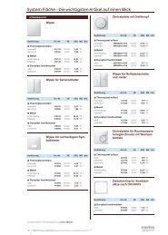
2 Gerät der gewünschten Anwendung entsprechend<br />
verdrahten.<br />
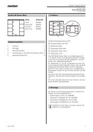
| Sie können beliebig viele Verbraucher an einen<br />
Eingang anschließen, solange der zulässige maximale<br />
Eingangsstrom von <strong>16</strong> A pro Kanal nicht<br />
überschritten wird. Die Kanäle 1-3 können mit beliebigen<br />
Phasen belegt werden.<br />
<strong>KNX</strong><br />
N<br />
L1<br />
L2<br />
L3<br />
3 Busspannung zuschalten.<br />
4 Spannungsversorgung der Verbraucher zuschalten.<br />
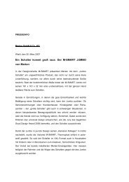
3<br />
N N 1 1 2 2 3 3<br />
B<br />
C<br />
D<br />
E<br />
<strong>Energiezähler</strong> in Betrieb nehmen<br />
1 Programmiertaste drücken: Die Programmier-LED<br />
leuchtet.<br />
2 Physikalische Adresse und Applikation aus der ETS<br />
in das Gerät laden: Die Programmier-LED erlischt.<br />
Die RUN-LED leuchtet: Die Applikation wurde erfolgreich<br />
geladen, das Gerät ist betriebsbereit.<br />
Status der LEDs<br />
Kanal-<br />
LED<br />
(rot/grün)<br />
Programmier-LED<br />
(rot)<br />
RUN-LED<br />
(grün)<br />
- AN - Physikalische<br />
Adresse kann<br />
geladen werden<br />
AUS - AN Applikation geladen<br />
und Busspannung<br />
liegt an<br />
blinkt<br />
grün<br />
- AN Messung wird<br />
durchgeführt<br />
AUS - AUS Keine Busspannung<br />
blinkt rot - AN Überlast<br />
Was tun bei Störungen?<br />
Verhalten bei Netzspannungsausfall an den Eingängen<br />
An allen Eingangskanälen kann keine Messung durchgeführt<br />
werden und das Statussignal ist nicht verfügbar.<br />
Die Kommunikation über den Bus ist möglich.<br />
Verhalten bei einem Busausfall und anliegender<br />
Spannung an den Eingängen<br />
Bei einem Busausfall wird die Messung sofort gestoppt<br />
und alle Informationen ab diesem Zeitpunkt werden nicht<br />
erfasst. Die RUN-LED ist ausgeschaltet.<br />
Verhalten nach Wiederherstellung der Busverbindung<br />
bei anliegender Spannung an den Eingängen<br />
Der vor dem Busausfall im internen Speicher abgelegte<br />
Verbrauchswert wird bei Buswiederkehr als Startpunkt<br />
der Energiezählung verwendet.<br />
Technische Daten<br />
Versorgungsspannung: via <strong>KNX</strong>-Bus, DC 24 V,<br />
max. 12,5 mA<br />
Bedienelemente: 1x Programmiertaste<br />
Anzeigelemente: 1x LED (rot): Programmierung<br />
1x LED (grün): RUN<br />
1x LED (rot/grün) pro Kanal:<br />
Status<br />
Eingänge:<br />
Spannung: AC 220/230 V, 50/60 Hz<br />
Max. Strom/Kanal: <strong>16</strong> A<br />
Min. Strom/Kanal: 20 mA (Leistungsfaktor 1)<br />
Externe Absicherung<br />
pro Kanal: <strong>16</strong> A<br />
Genauigkeitsklasse: gemäß IEC 61557-12<br />
Wirkenergiemessung: Klasse 1<br />
Umgebungstemperatur:<br />
Betrieb: -5 °C bis +45 °C<br />
Umgebung: Einsatzhöhe bis 2000 m über<br />
Meereshöhe (MSL)<br />
Max. Feuchtigkeit: 93 %, ohne Betauung<br />
Anschlüsse<br />
<strong>KNX</strong>: Busanschlussklemme<br />
Eingänge: Schraubklemme für Querschnitte<br />
bis max. 2,5 mm 2<br />
Schutzart: IP 20<br />
Gerätebreite (HxBxT): 90x72x65 mm , 4 TE<br />
Merten GmbH<br />
Merten GmbH, Fritz-Kotz-Str. 8, D-5<strong>16</strong>74 Wiehl<br />
www.merten.de<br />
Service Center (Warenrücksendung):<br />
Telefon: +49 2261 702-204<br />
Telefax: +49 2261 702-136<br />
E-Mail: servicecenter@merten.de<br />
Technische Auskünfte / InfoLine:<br />
Telefon: +49 2261 702-235<br />
Telefax: +49 2261 702-680<br />
E-Mail: infoline.merten@schneider-electric.com<br />
S1B45115-00 02/12
<strong>KNX</strong> Energy Meter, <strong>REG</strong>-K/<strong>3x230</strong> V/<strong>16</strong> AMEG6600-0603© Merten 2009S1B45115-0002/12<br />
de<br />
en<br />
<strong>KNX</strong> Energy Meter, <strong>REG</strong>-K/<strong>3x230</strong> V/<br />
<strong>16</strong> A<br />
Operating instructions<br />
1 2 3<br />
N N 1 1 2 2 3 3<br />
Art. no. MEG6600-0603<br />
For your safety<br />
¼ DANGER<br />
Risk of serious damage to property and personal<br />
injury, e.g. from fire or electric shock,<br />
due to incorrect electrical installation.<br />
Safe electrical installation can only be ensured if<br />
the person in question can prove basic knowledge<br />
in the following areas:<br />
• Connection to installation networks<br />
• Connecting several electrical devices<br />
• Laying electric cables<br />
• Connecting and establishing <strong>KNX</strong> networks<br />
These skills and experience are normally only<br />
possessed by skilled professionals who are<br />
trained in the field of electrical installation technology.<br />
If these minimum requirements are not met<br />
or are disregarded in any way, you will be solely liable<br />
for any damage to property or personal injury.<br />
Getting to know the Energy Meter<br />
The <strong>KNX</strong> Energy Meter, <strong>REG</strong>-K/<strong>3x230</strong> V/<strong>16</strong> A (referred<br />
to below as Energy Meter) makes it possible to monitor<br />
and measure energy on the channels connected.<br />
Device properties<br />
• Measurement of: active energy consumption, power<br />
and current and providing the results via the bus.<br />
• Determining the active energy consumption per channel<br />
and the total energy consumption.<br />
• Accuracy of the measurement of the active energy<br />
consumption per channel: max. 1.5%<br />
• Accuracy of power and current measurement<br />
(calculated): 10%<br />
• The ETS enables the functions below:<br />
- energy saving functions (switching, dimming, scene,<br />
etc.)<br />
- alarm functions (alarm above/under limit)<br />
• For installation on TH35 DIN rails as per<br />
DIN EN 60715.<br />
• The bus connection is carried out via a bus connecting<br />
terminal.<br />
| Never use the device in combination with current<br />
transformers.<br />
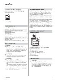
Connections, displays and <strong>operating</strong><br />
elements<br />
1 2 3<br />
A<br />
N N 1 1 2 2 3 3<br />
F<br />
A Connection: bus<br />
B Protective cap for A<br />
C Push-button and LED: programming<br />
D LED: RUN<br />
E LED: channel 1-3<br />
F Connecting terminals<br />
Mounting the Energy Meter<br />
¼ WARNING<br />
Risk of death from electric shock. The device<br />
can be damaged.<br />
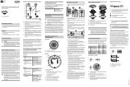
Safety clearance must be guaranteed in accordance<br />
with IEC 60664-1. There must be at least<br />
4 mm between the individual cores of the 230 V<br />
supply cable and the <strong>KNX</strong> line A.<br />
230 V<br />
4 mm<br />
1 Place the device into the DIN rail.<br />
1<br />
2<br />
2 Wire the device of the desired application accordingly.<br />
| You can connect any number of loads to an input<br />
as long as the allowed maximum input current of<br />
<strong>16</strong> A per channel is not exceeded. Any phases<br />
can be assigned to channels 1-3.<br />
<strong>KNX</strong><br />
N<br />
L1<br />
L2<br />
L3<br />
B<br />
C<br />
D<br />
E<br />
3 Connect the bus voltage.<br />
4 Connect the power supply to the loads.<br />
A<br />
3<br />
N N 1 1 2 2 3 3<br />
Putting the Energy Meter into operation<br />
1 Press the programming button: the programming<br />
LED lights up.<br />
2 Load the physical address and application into the<br />
device from the ETS: The programming LED goes<br />
out.<br />
The RUN LED lights up: the application has been loaded<br />
successfully, the device is ready to be operated.<br />
Status of the LEDs<br />
Status Program- RUN<br />
LED ming LED LED<br />
(red/green) (red) (green)<br />
- ON - The physical address<br />
can be loaded<br />
OFF - ON Application loaded<br />
and bus voltage<br />
connected<br />
Flashes - ON Measurement being<br />
green<br />
performed<br />
OFF - OFF No bus voltage<br />
Flashes<br />
red<br />
- ON Overload<br />
What should I do if there is a problem?<br />
Behaviour in the event of load voltage (mains) failure<br />
at the inputs<br />
No measurements can be performed on any of the input<br />
channels and the status signal is not available. Communication<br />
via the bus is possible.<br />
Behaviour in the event of bus failure when load voltage<br />
(mains) is connected at the inputs<br />
In the event of bus failure, measurement is stopped immediately<br />
and all information from this point on is not recorded.<br />
The RUN LED is switched off.<br />
Behaviour after restoring the bus connection when<br />
load voltage (mains) is connected at the inputs<br />
The consumption value saved in the internal memory prior<br />
to bus failure is used as the starting point for power<br />
measurement when the bus connection is restored.<br />
Technical data<br />
Supply voltage: via <strong>KNX</strong> bus, DC 24 V,<br />
max. 12.5 mA<br />
Operating elements: 1x programming button<br />
Display elements: 1x LED (red): Programming<br />
1x LED (green): RUN<br />
1x LED (red/green) per channel:<br />
Status<br />
Inputs:<br />
Voltage: AC 220/230 V, 50/60 Hz<br />
Max. current/channel: <strong>16</strong> A<br />
Min. current/channel: 20 mA (power factor 1)<br />
External protection<br />
per channel: <strong>16</strong> A<br />
Accuracy class: according to IEC 61557-12<br />
Active energy<br />
measurement: Class 1<br />
Ambient temperature:<br />
Operation: -5 °C to +45 °C<br />
Environment: Can be used at elevations up<br />
to 2000 m above sea level<br />
(MSL)<br />
Max. humidity: 93%, no condensation<br />
Connections<br />
<strong>KNX</strong>: Bus connecting terminal<br />
Inputs: Screw terminal for crosssections<br />
up to max. 2.5 mm 2<br />
Type of protection: IP 20<br />
Device width (HxWxD): 90x72x65 mm , 4 modules<br />
Merten GmbH<br />
Merten GmbH, Fritz-Kotz-Str. 8, D-5<strong>16</strong>74 Wiehl<br />
www.merten.com<br />
Service Center:<br />
Phone: +49 2261 702-204<br />
Fax: +49 2261 702-136<br />
E-Mail: servicecenter@merten.de<br />
Technical support / InfoLine:<br />
Phone: +49 2261 702-235<br />
Fax: +49 2261 702-680<br />
E-Mail: infoline.merten@schneider-electric.com<br />
S1B45115-00 02/12