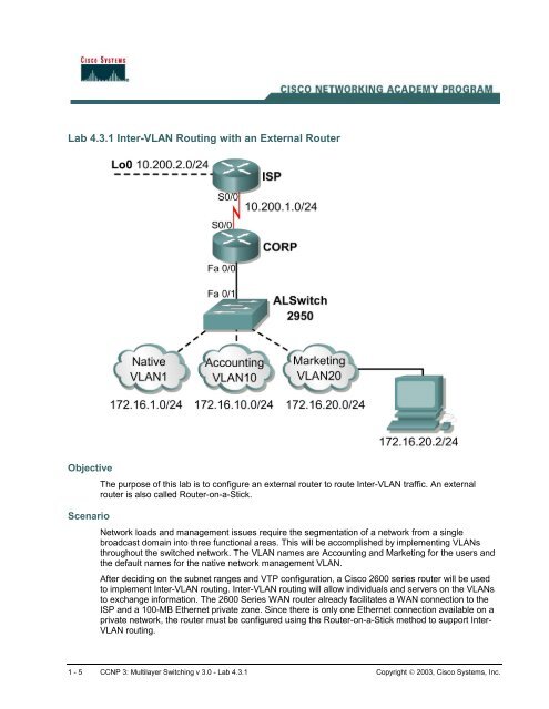
Lab 4.3.1 Inter-VLAN Routing with an External Router
Lab 4.3.1 Inter-VLAN Routing with an External Router
Lab 4.3.1 Inter-VLAN Routing with an External Router

You also want an ePaper? Increase the reach of your titles
YUMPU automatically turns print PDFs into web optimized ePapers that Google loves.
<strong>Lab</strong> <strong>4.3.1</strong> <strong>Inter</strong>-<strong>VLAN</strong> <strong>Routing</strong> <strong>with</strong> <strong>an</strong> <strong>External</strong> <strong>Router</strong><br />
Objective<br />
The purpose of this lab is to configure <strong>an</strong> external router to route <strong>Inter</strong>-<strong>VLAN</strong> traffic. An external<br />
router is also called <strong>Router</strong>-on-a-Stick.<br />
Scenario<br />
Network loads <strong>an</strong>d m<strong>an</strong>agement issues require the segmentation of a network from a single<br />
broadcast domain into three functional areas. This will be accomplished by implementing <strong>VLAN</strong>s<br />
throughout the switched network. The <strong>VLAN</strong> names are Accounting <strong>an</strong>d Marketing for the users <strong>an</strong>d<br />
the default names for the native network m<strong>an</strong>agement <strong>VLAN</strong>.<br />
After deciding on the subnet r<strong>an</strong>ges <strong>an</strong>d VTP configuration, a Cisco 2600 series router will be used<br />
to implement <strong>Inter</strong>-<strong>VLAN</strong> routing. <strong>Inter</strong>-<strong>VLAN</strong> routing will allow individuals <strong>an</strong>d servers on the <strong>VLAN</strong>s<br />
to exch<strong>an</strong>ge information. The 2600 Series WAN router already facilitates a WAN connection to the<br />
ISP <strong>an</strong>d a 100-MB Ethernet private zone. Since there is only one Ethernet connection available on a<br />
private network, the router must be configured using the <strong>Router</strong>-on-a-Stick method to support <strong>Inter</strong>-<br />
<strong>VLAN</strong> routing.<br />
1 - 5 CCNP 3: Multilayer Switching v 3.0 - <strong>Lab</strong> <strong>4.3.1</strong> Copyright © 2003, Cisco Systems, Inc.
The VTP design information is as follows:<br />
VTP Domain VTP Mode<br />
CORP Server<br />
The <strong>VLAN</strong> configuration information is as follows:<br />
<strong>VLAN</strong> ID <strong>VLAN</strong> Name <strong>VLAN</strong> Subnet <strong>VLAN</strong> Gateway Switch Ports<br />
1 Native 172.16.1.0 172.16.1.1/24 Fa0/1-4<br />
Fa0/13-24<br />
10 Accounting 172.16.10.0 172.16.10.1/24 Fa0/5-8<br />
20 Marketing 172.16.20.0 172.16.20.1/24 FA0/9-12<br />
Trunk 802.1Q<br />
The 2600 <strong>Inter</strong>face configuration information is as follows:<br />
<strong>Inter</strong>face IP Address <strong>VLAN</strong><br />
FastEthernet 0/0.1 172.16.1.1 1 Native<br />
FastEthernet 0/0.10 172.16.10.1 10<br />
FastEthernet 0/0.20 172.16.20.1 20<br />
Serial0/0 10.200.1.2<br />
Step 1<br />
Do not cable the lab until the router configurations, switch configurations, <strong>an</strong>d switch vl<strong>an</strong>.dat file<br />
have been erased.<br />
Delete the vl<strong>an</strong> database if it exists on <strong>an</strong>y switches <strong>an</strong>d clear the configuration.<br />
switch#delete flash:vl<strong>an</strong>.dat<br />
Delete filename [vl<strong>an</strong>.dat]?<br />
Delete flash:vl<strong>an</strong>.dat? [confirm]<br />
switch#<br />
switch#erase startup-config<br />
Erasing the nvram filesystem will remove all files! Continue? [confirm]<br />
DLSwitchA#reload<br />
System configuration has been modified. Save? [yes/no]:n<br />
Proceed <strong>with</strong> reload? [confirm]<br />
Cable the lab according to the diagram.<br />
2 - 5 CCNP 3: Multilayer Switching v 3.0 - <strong>Lab</strong> <strong>4.3.1</strong> Copyright © 2003, Cisco Systems, Inc.
Step 2<br />
Configure ISP for communication <strong>with</strong> the CORP router.<br />
<strong>Router</strong>(config)#hostname ISP<br />
ISP(config)#interface Loopback0<br />
ISP(config-if)#ip address 10.200.2.1 255.255.255.0<br />
ISP(config)#interface Serial0/0<br />
ISP(config-if)#ip address 10.200.1.1 255.255.255.0<br />
ISP(config-if)#clockrate 56000<br />
ISP(config-if)#no shutdown<br />
ISP(config)#ip route 172.16.0.0 255.255.0.0 10.200.1.2<br />
The ISP router is not part of the main network. The static route will provide a path back to the local<br />
network.<br />
Configure the CORP router to communicate <strong>with</strong> the ISP router.<br />
<strong>Router</strong>(config)#hostname CORP<br />
CORP(config)#interface Serial0/0<br />
CORP(config-if)#ip address 10.200.1.2 255.255.255.0<br />
CORP(config-if)#no shutdown<br />
CORP(config-if)#exit<br />
CORP(config-if)#ip route 10.200.2.0 255.255.255.0 10.200.1.1<br />
CORP(config)#exit<br />
Verify the connectivity between ISP <strong>an</strong>d CORP router.<br />
1. How was the connectivity verified?<br />
_____________________________________________________________________<br />
Step 3<br />
Set the duplex mode to full <strong>an</strong>d enable the interface.<br />
The router must now use the same trunking protocol to communicate <strong>with</strong> the switch. The two<br />
primary trunking protocols are the Cisco proprietary <strong>Inter</strong>Switch Link (ISL) <strong>an</strong>d 802.1q, or dot1q.<br />
Dot1q trunking will be used in this lab.<br />
CORP(config)#interface fastethernet 0/0<br />
CORP(config-if)#full-duplex<br />
CORP(config-if)#no shutdown<br />
The native <strong>VLAN</strong> c<strong>an</strong>not be configured on a subinterface for Cisco IOS releases that are earlier th<strong>an</strong><br />
12.1(3)T. The native <strong>VLAN</strong> ip address will need to be configured on the physical interface. Other<br />
<strong>VLAN</strong> traffic will be configured on subinterfaces. Cisco IOS releases 12.1(3)T <strong>an</strong>d later will support<br />
native <strong>VLAN</strong> configuration on a subinterface <strong>with</strong> the encapsulation encapsulation vl<strong>an</strong>_id<br />
native comm<strong>an</strong>d. This technique will be used in the lab configuration.<br />
Create a sub-interface for each <strong>VLAN</strong>. Enable each sub-interface <strong>with</strong> the proper trunking protocol<br />
<strong>an</strong>d tie it to a particular <strong>VLAN</strong> <strong>with</strong> the encapsulation comm<strong>an</strong>d.<br />
Assign <strong>an</strong> IP address to each sub-interface that hosts on the <strong>VLAN</strong> c<strong>an</strong> use for a default gateway.<br />
<strong>VLAN</strong> 1 interface<br />
CORP(config)#interface fastethernet 0/0.1<br />
CORP(config-subif)#description M<strong>an</strong>agement <strong>VLAN</strong> 1<br />
CORP(config-subif)#encapsulation dot1q 1 native<br />
CORP(config-subif)#ip address 172.16.1.1 255.255.255.0<br />
3 - 5 CCNP 3: Multilayer Switching v 3.0 - <strong>Lab</strong> <strong>4.3.1</strong> Copyright © 2003, Cisco Systems, Inc.
Step 4<br />
<strong>VLAN</strong> 10 interface<br />
CORP(config)#interface fastethernet 0/0.10<br />
CORP(config-subif)#description Accounting <strong>VLAN</strong> 10<br />
CORP(config-subif)#encapsulation dot1q 10<br />
CORP(config-subif)#ip address 172.16.10.1 255.255.255.0<br />
<strong>VLAN</strong> 20 interface<br />
CORP(config)#interface fastethernet 0/0.20<br />
CORP(config-subif)#description Marketing <strong>VLAN</strong> 20<br />
CORP(config-subif)#encapsulation dot1q 20<br />
CORP(config-subif)#ip address 172.16.20.1 255.255.255.0<br />
Use the show ip interface brief comm<strong>an</strong>d to verify proper interface configuration <strong>an</strong>d<br />
status.<br />
Configure the hostname, password, <strong>an</strong>d Telnet access for the switch.<br />
Switch(config)#hostname ALSwitch<br />
ALSwitch(config)#enable secret cisco<br />
ALSwitch(config)#line vty 0 4<br />
ALSwitch(config-line)#password cisco<br />
ALSwitch(config-line)#login<br />
ALSwitch(config-line)#exit<br />
Create a virtual interface on the switch for <strong>VLAN</strong> 1 <strong>an</strong>d assign <strong>an</strong> IP address. This will be the IP<br />
address for the switch. The switch will be set to 172.16.1.2 because the router gateway address is<br />
set to 172.16.1.1.<br />
ALSwitch(config)#interface <strong>VLAN</strong> 1<br />
ALSwitch(config-if)#ip address 172.16.1.2 255.255.255.0<br />
ALSwitch(config-if)#no shutdown<br />
ALSwitch(config-if)#exit<br />
Create a default gateway that will be used to pass packets to the interface on the m<strong>an</strong>agement<br />
<strong>VLAN</strong> router.<br />
ALSwitch(config)#ip default-gateway 172.16.1.1<br />
2. Why is the ip default-gateway comm<strong>an</strong>d used?<br />
___________________________________________________________________<br />
Step 5<br />
Configure the switch for trunking <strong>an</strong>d assign <strong>VLAN</strong>s as specified in the table at the beginning of the<br />
lab.<br />
Set the interface connected to the router to trunk <strong>with</strong> the router. The router is already set to trunk<br />
<strong>with</strong> the <strong>VLAN</strong> subinterfaces. The default encapsulation is 802.1Q. Therefore, the switchport<br />
trunk encapsulation dot1q comm<strong>an</strong>d is not necessary.<br />
ALSwitch(config)#interface fastethernet 0/1<br />
ALSwitch(config-if)#switchport mode trunk<br />
4 - 5 CCNP 3: Multilayer Switching v 3.0 - <strong>Lab</strong> <strong>4.3.1</strong> Copyright © 2003, Cisco Systems, Inc.
Step 6<br />
Look at the interface <strong>an</strong>d CDP information to verify that the trunking is working properly.<br />
ALSwitch#show interface fastethernet 0/1 switchport<br />
3. What is the IP address of the neighbor?<br />
___________________________________________________________________<br />
Place the ports in the correct <strong>VLAN</strong> <strong>an</strong>d configure PortFast.<br />
ALSwitch(config)#interface r<strong>an</strong>ge fastethernet 0/5 - 8<br />
ALSwitch(config-if)#switchport access vl<strong>an</strong> 10<br />
ALSwitch(config-if)#sp<strong>an</strong>ning-tree portfast<br />
ALSwitch(config)#interface r<strong>an</strong>ge fastethernet 0/9 - 12<br />
ALSwitch(config-if)#switchport access vl<strong>an</strong> 20<br />
ALSwitch(config-if)#sp<strong>an</strong>ning-tree portfast<br />
Verify the configuration <strong>an</strong>d host access after completing the configuration of the switch <strong>an</strong>d router.<br />
Ensure that the workstation is connected to a port on the switch that is set to <strong>VLAN</strong> 20 such as port<br />
9. The workstation IP address should be set to 172.16.20.2/24 <strong>with</strong> a gateway of 172.16.20.1.<br />
Ping the following addresses from a comm<strong>an</strong>d prompt on the workstation.<br />
C:\>ping 172.16.20.1<br />
C:\>ping 172.16.1.2<br />
C:\>ping 10.200.1.1<br />
C:\>ping 10.200.1.2<br />
C:\>ping 10.200.2.1<br />
If a ping fails, return to the router <strong>an</strong>d switch <strong>an</strong>d take corrective action.<br />
Step 7<br />
Verify that the switch c<strong>an</strong> be m<strong>an</strong>aged from a workstation on <strong>VLAN</strong> 10 or <strong>VLAN</strong> 20. The workstation<br />
traffic must leave the <strong>VLAN</strong> at the router to connect to the switch. The router will forward the traffic to<br />
the switch m<strong>an</strong>agement <strong>VLAN</strong>. The process is repeated in reverse for switch traffic that is destined<br />
for the workstation.<br />
Telnet to the switch from the DOS comm<strong>an</strong>d prompt on the workstation. Log in <strong>with</strong> the cisco<br />
password.<br />
C:\>telnet 172.16.1.2<br />
4. Did the Telnet work? __________<br />
5 - 5 CCNP 3: Multilayer Switching v 3.0 - <strong>Lab</strong> <strong>4.3.1</strong> Copyright © 2003, Cisco Systems, Inc.