FORCE MEASURING SYSTEMS - METRON
FORCE MEASURING SYSTEMS - METRON
FORCE MEASURING SYSTEMS - METRON

You also want an ePaper? Increase the reach of your titles
YUMPU automatically turns print PDFs into web optimized ePapers that Google loves.
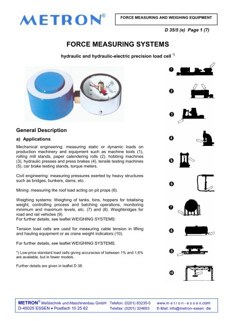
General Description<br />
a) Applications<br />
<strong>FORCE</strong> <strong>MEASURING</strong> AND WEIGHING EQUIPMENT<br />
<strong>FORCE</strong> <strong>MEASURING</strong> <strong>SYSTEMS</strong><br />
hydraulic and hydraulic-electric precision load cell *)<br />
Mechanical engineering: measuring static or dynamic loads on<br />
production machinery and equipment such as machine tools (1),<br />
rolling mill stands, paper calendering rolls (2), hobbing machines<br />
(3), hydraulic presses and press brakes (4), tensile testing machines<br />
(5), car brake testing stands, torque meters.<br />
Civil engineering: measuring pressures exerted by heavy structures<br />
such as bridges, bunkers, dams, etc.<br />
Mining: measuring the roof load acting on pit props (6).<br />
Weighing systems: Weighing of tanks, bins, hoppers for totalising<br />
weight, controlling process and batching operations, monitoring<br />
minimum and maximum levels, etc. (7) and (8). Weighbridges for<br />
road and rail vehicles (9).<br />
For further details, see leaflet WEIGHING <strong>SYSTEMS</strong>:<br />
Tension load cells are used for measuring cable tension in lifting<br />
and hauling equipment or as crane weight indicators (10).<br />
For further details, see leaflet WEIGHING <strong>SYSTEMS</strong>.<br />
*) Low-price standard load cells giving accuracies of between 1% and 1,6%<br />
are available, but in fewer models.<br />
Further details are given in leaflet D 38.<br />
D 35/5 (e) Page 1 (7)<br />
<strong>METRON</strong> ® Meßtechnik und Maschinenbau GmbH Telefon: (0201) 83235-0 www.m e t r o n - e s s e n.com<br />
D-45025 ESSEN • Postfach 10 25 62 Telefax: (0201) 324653 E-Mail: info@metron–essen. de
) Design<br />
<strong>FORCE</strong> <strong>MEASURING</strong> AND WEIGHING EQUIPMENT<br />
D 35/5 (e) Seite 2 ( 7)<br />
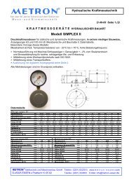
Hydraulic load cells consist essentially of a cylindrical or ring-type capsule with piston and a specially<br />
developed oil- and acid-resistant diaphragm which hermetically seals the fluid system. On loading the piston,<br />
the pressure generated in the fluid is transmitted via the diaphragm to the indicator gauge. The stroke of the<br />
piston does not exceed 1 mm.<br />
Indicators have scales calibrated in N, kN oder MN and are normally available in diameters of 100 or 160<br />
mm, or in rectangular sizes of 72 x 72, 96 x 96, 144 x 144 and 144 x 72 mm.<br />
Hydraulic load cells, owing to their simple and robust design, are insensitive to shock and vibration and yet<br />
provide high-accuracy readings; they can be used in ambient temperatures ranging from -20°C to +50°C.<br />
Higher temperature resistance is offered, on request.<br />
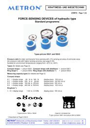
c) Remote Indication<br />
Capillary tubing of between 2 and 15 m length can be used to transmit the load cell output to the indicator or<br />
recorder. This 4 mm dia. tubing is available in copper or steel, provided with stainless steel covering, if<br />
necessary.<br />
d) Electrical Contact Units<br />
Indicators and certain types of recorders can be provided with electrical contact units designed to give visual<br />
or audible signals whenever the actual load exceeds or falls below a pre-set value.<br />
For type selection, see leaflet EK 01.<br />
Pressure Switch<br />
The load cells may also be fitted with a special pressure switch.<br />
For further details, see leaflet EK 02.<br />
f) Hydraulic Line Coupling (Reg. Design)<br />
Capillaries of greater length can be provided with a self-sealing coupling at any point between load cell and<br />
indicator (recorder) to facilitate the installation on machinery.<br />
Further details are given in the Operating Instructions.<br />
<strong>METRON</strong> ® Meßtechnik und Maschinenbau GmbH Telefon: (0201) 83235-0 www.m e t r o n - e s s e n.com<br />
D-45025 ESSEN • Postfach 10 25 62 Telefax: (0201) 324653 E-Mail: info@metron–essen. de
g) Accuracy<br />
<strong>FORCE</strong> <strong>MEASURING</strong> AND WEIGHING EQUIPMENT<br />
D 35/5 (e) Seite3 ( 7)<br />
Indicator readings normally are accurate to ± 1 % of full scale or, in special casas, to ± 0,6 %, always<br />
provided the load to be measured is acting centrally and normal to the piston face. To ensure this, the cell<br />
must be mounted in perfectly horizontal position and parallel to the upper and lower compression faces. The<br />
load must act on the full piston face and the piston must not be subjected to side loads or shear forces.<br />
Additional instruments cause the accuracy to decrease. Detailed information is given on request.<br />
h) Overload Capacity / Overload Protection / Shock Load Damping<br />
To determine the correct measuring range and to prevent overloading, multiply the maximum service load by<br />
1.2 if the load is static, or by 1.5 if the load is dynamic, and choose the next higher standard range. Normally,<br />
pressure gauges can be loaded to full scale. If desired, we supply pressure gauges that can be subjected to<br />
short-cycle overloads equal to 1.2 times the full scale.<br />
A dual snubber can be incorporated to dampen out shock loads in both directions.<br />
For further details, see leaflet MZ 02-01.<br />
i Other Features<br />
Pressure gauges are also available in outdoor design; they can be arranged in any position or can be fitted<br />
with a maximum pointer and any apecial scale or scale graduation. This publication covers our normal range<br />
of load cells. If other designs are required, please give detailed information on proposed application, location<br />
(outdoors?), service pressure, desired or permissible size, etc.-If load cell is to be installed on a machine,<br />
send drawing or detail drawing of the machine.<br />
The load cells described herein are not suitable for measuring shock loads on high-speed presses.<br />
This application requires the use of electrical output load cells with peak-load storage.<br />
For further details, see leaflet D 81.<br />
k) Special-Purpose Load Cells<br />
Clamping force sensors; see leaflet D 30.<br />
l) Operating Instructions<br />
See leaflet BA-D 11.<br />
<strong>METRON</strong> ® Meßtechnik und Maschinenbau GmbH Telefon: (0201) 83235-0 www.m e t r o n - e s s e n.com<br />
D-45025 ESSEN • Postfach 10 25 62 Telefax: (0201) 324653 E-Mail: info@metron–essen. de
<strong>FORCE</strong> <strong>MEASURING</strong> AND WEIGHING EQUIPMENT<br />
Typical Designs<br />
Load Cell Gauge Connection Gauge Type<br />
D 35/5 (e) Page 4 ( 7)<br />
1. circular gauge, 100, 160 mm dia.<br />
1. cylindrical type 1. rigid as standard<br />
2. ring type 2. rigid, extended<br />
3. spezial typ for weighing systems 3. rigid, with angular extension<br />
2. circular gauge for surface-mounting<br />
100, 160 mm dia.<br />
3. circular gauge with wall bracket<br />
How to order: 4. circular gauge for flush-mounting,<br />
Example: Type 5.2.4.7 with front ring A, 100, 160 mm dia.<br />
5 = load cell system<br />
2 = ring-type load cell<br />
4 = capillary tubing<br />
7 = edgewise indicator,<br />
In addition, please specify:<br />
a) load cell with 1 or 2 carrying<br />
handles.<br />
5. circular gauge for flush-mounting,<br />
4. cooper or steel capillary with rear rim and front ring B,<br />
tubing as hydraulic line 100, 160 mm dia.<br />
b) self-sealing coupling,if desired 6. square dial i6. sqare dial indicator, 144 x 144 mm<br />
c) size of gauge or indicator<br />
d if gauge (items 1-5) shall be of<br />
corrosion-resistant standard type,<br />
100 or 160 mm dia.<br />
e) if gauge indicator is to be fitted 5. high-pressure hose as 7. rectangular edgewise indicator<br />
with electrical contacts or other hydraulic line 144 x 72 mm<br />
devices<br />
<strong>METRON</strong> ® Meßtechnik und Maschinenbau GmbH Telefon: (0201) 83235-0 www.m e t r o n - e s s e n.com<br />
D-45025 ESSEN • Postfach 10 25 62 Telefax: (0201) 324653 E-Mail: info@metron–essen. de
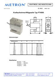
Range of Types<br />
Cylindrical Load Cells<br />
<strong>FORCE</strong> <strong>MEASURING</strong> AND WEIGHING EQUIPMENT<br />
D35/5 (e) Page 5 ( 7)<br />
Range limit Scale-<br />
Dimensions in mm<br />
Type kN / MN kp / Mp graduation<br />
for load cell<br />
1) a b c d<br />
Net-<br />
weight<br />
kg 2)<br />
N / 0,6 0 – 0,6 kN 0 – 60 kp 0,01 kN 65 30 65 22 2,6<br />
N / 1,0 0 – 1,0 kN 0 – 100kp 0,02 kN 65 30 65 22 2,6<br />
N / 1,6 0 – 1,6 kN 0 – 160 kp 0,05 kN 65 30 65 22 2,6<br />
N / 2,5 0 – 2,5 kN 0 – 250 kp 0,05 kN 65 30 65 22 2,6<br />
N / 4,0 0 – 4,0 kN 0 – 400 kp 0,10 kN 65 30 65 22 2,6<br />
N / 6,0 0 – 6,0 kN 0 – 600 kp 0,10 kN 100 50 75 23 5,5<br />
N / 10,0 0 – 10 kN 0 – 1,0 Mp 0,20 kN 100 50 75 23 5,5<br />
N / 16,0 0 – 16 kN 0 – 1,6 Mp 0,50 kN 100 50 75 23 5,5<br />
N / 25,0 0 – 25 kN 0 – 2,5 Mp 0,50 kN 100 50 75 23 5,5<br />
N / 40,0 0 – 40 kN 0 – 4,0 Mp 1,00 kN 100 50 75 23 5,5<br />
N / 60 0 – 60 kN 0 – 6,0 Mp 1,00 kN 160 100 100 28 16,0<br />
N / 100 0 – 100 kN 0 – 10 Mp 2,00 kN 160 100 100 28 16,0<br />
N / 160 0 – 160 kN 0 – 16 Mp 5,00 kN 160 100 100 28 16,0<br />
N / 250 0 – 250 kN 0 – 25 Mp 5,00 kN 160 100 100 28 16,0<br />
N / 400 0 – 400 kN 0 – 40 Mp 10,00 kN 160 100 100 28 16,0<br />
N / 600 0 – 600 kN 0 – 60 Mp 10,00 kN 160 100 100 28 16,0<br />
N / 1000 0 – 1,0 MN 0 – 100 Mp 0,02 MN 200 140 110 30 27,0<br />
N / 1600 0 – 1,6 MN 0 – 160 Mp 0,05 MN 240 170 120 30 40,0<br />
N / 2500 0 – 2,5 MN 0 – 250 Mp 0,05 MN 290 210 130 30 62,0<br />
N / 4000 0 – 4,0 MN 0 – 400 MP 0,10 MN 350 270 130 30 90,0<br />
N / 6000 0 – 6,0 MN 0 – 600 MP 0,10 MN 370 270 130 35 102,0<br />
N / 10000 0 – 10 MN 0 – 1000 Mp 0,20 MN 470 350 165 55 210,0<br />
1) Finely subvided scale or 160 mm dia. pecision gauge optional.<br />
2) Net weight for load cells with indicator gauge 100 mm dia.<br />
Ring-type Load Cells<br />
These types are made to customer`s specification. Dimension D shall be at least d + 120 mm and the depth<br />
between 70 and 75 mm, if possible. In spezial cases where lack of space forbids the use of a cell size conforming<br />
to the above diameter/depth ratio, please state the required load range and the space available for<br />
installation.<br />
<strong>METRON</strong> ® Meßtechnik und Maschinenbau GmbH Telefon: (0201) 83235-0 www.m e t r o n - e s s e n.com<br />
D-45025 ESSEN • Postfach 10 25 62 Telefax: (0201) 324653 E-Mail: info@metron–essen. de
Dimensions of Circular Gauges<br />
Nom. Size<br />
D<br />
in mm<br />
<strong>FORCE</strong> <strong>MEASURING</strong> AND WEIGHING EQUIPMENT<br />
Fig. 101 Fig. 102 Fig. 103<br />
Fig. 104 Fig. 105 Fig. 106<br />
Fig. 107 Fig. 108 Fig. 109<br />
a1 a2 a3 b1 b2<br />
Single -<br />
Contact<br />
b3<br />
Double-<br />
Contakt<br />
Dimensions in mm<br />
Single -<br />
Contact<br />
D35/5 (e) Page 6 ( 7)<br />
<strong>METRON</strong> ® Meßtechnik und Maschinenbau GmbH Telefon: (0201) 83235-0 www.m e t r o n - e s s e n.com<br />
D-45025 ESSEN • Postfach 10 25 62 Telefax: (0201) 324653 E-Mail: info@metron–essen. de<br />
b5<br />
Double-<br />
Contact D D1 d1 d2 d3 e h s<br />
100 15,5 19 30 49,5 53 87 87 100 100 99 101 116 132 4,8 5,5 87 6<br />
160 15,5 19 50 49,5 53 87 87 100 100 159 161 178 192 5,8 7 118 6<br />
Fig. 101 = standard gauge to DIN 16 064, Style A, with bottom connection<br />
Fig. 102 = same as Fig. 101, with back rim for surface-mounting, to DIN 16 064, style B<br />
Fig. 103 = same as Fig. 101, with front ring for flush-mounting, to DIN 16 280, style A<br />
Fig. 104 = with eccentric rear connection<br />
Fig. 105 = same as Fig. 104, with back rim for surface-mounting, to DIN 16 064, style B<br />
Fig. 106 = same as Fig. 104, with front ring for flusch-mounting, to DIN 16 280, style A<br />
Fig. 107 = stainless steel gauge, with bottom connection<br />
Fig. 108 = contact-making gauge (Fig.101 with contacts, rear cable inlet)<br />
Fig. 109 = contact-making gauge (Fig. 107 with cantacts)
Dimensions of Square and Rectangular Indicators<br />
NS<br />
<strong>FORCE</strong> <strong>MEASURING</strong> AND WEIGHING EQUIPMENT<br />
D35/5 (e) Seite 7 ( 7)<br />
NS 48 x 24, with eccentric rear connection NS 72 x 36, with eccentric rear connection<br />
NS 72 x 72, 96 x 96, 144 x 144, NS 144 x 72, with eccentric rear connection<br />
with eccentric rear connection<br />
Dimensions in mm<br />
b1 b6 e f G L L1 l l1 pxp1 p ? SW<br />
Weight<br />
in kg<br />
48 x 24 75,5 83,5 2 14 G 1/8 A 48 24 38 14 44,5x20,5 - - 0,17<br />
72 x 36 74,5 86,5 4 21 G ¼ A 72 36 56 20 66 x 29 - 14 0,25<br />
72 x 72 29 42 6 - G ¼ A 72 - 62 - - 66 14 0,30<br />
96 x 96 35 47 6 - G ¼ A 96 - 79 - - 88,5 14 0,40<br />
144 x 72 168 197 8 18 G ½ A 144 72 134 62 134 x 63,5 - 17 1,50<br />
144 x 144 46,5 72 8 30 G ½ A 144 - 134 - 136 22 1,50<br />
Technical modification excepted. Stand 18.08.2005<br />
<strong>METRON</strong> ® Meßtechnik und Maschinenbau GmbH Telefon: (0201) 83235-0 www.m e t r o n - e s s e n.com<br />
D-45025 ESSEN • Postfach 10 25 62 Telefax: (0201) 324653 E-Mail: info@metron–essen. de